

Page 1
INSTRUCTION
MANUAL
TVPE
IMPEDANCE
1650-B
BRIDGE
GENERAL
A
RADIO
COMPANY
Page 2
I
NSTR
UCT
ION
MANUAL
TVPE
IMPEDANCE
165D-B
Form
BRIDGE
165G-012G-A
10-0100
April,1968
GENERAL RADIO
West
Copyright
Con
1968,
co
rd,
M
General
assach
Radio
u
setts
Company
Page 3
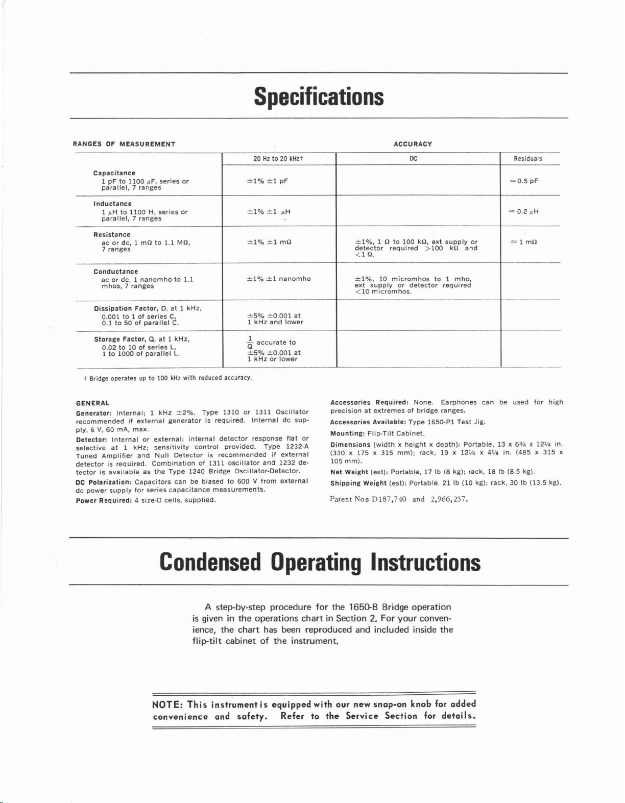
Specifications
RANGESOFMEASUREMENT
Capacitance
1pFto
1100
/-IF,
parallel,7ranges
Inductance
1
/-lHto1100H,series
parallel,7ranges
Resistance
acordc,
7
ranges
Conductance
acordc,1nanomhoto1.1
mhos,7ranges
Oissipation
0.001to1ofseries
0.1to50ofparallel
Storage
Factor,Q,at1kHz,
0.02to10ofseries
1to1000ofparallel
t Bridge operates
GENERAL
Generator:
recommendedifexternal
ply,6V,60mA,
Detector:
selectiveat1
Tuned
detectorisrequired.
tectorisavailableasthe
DC
dc
Power
Internal;1kHz
Internalorexternal;
Amplifier
Polarization:
power
supply
Required:
series
1 mOto1.1 MO,
Factor,D,at1kHz,
upto100
max.
kHz;
sensitivity
and
Null
Combinationof1311
Capacitors
for
series
4 size-D
cells,
20Hzto
20
or
or
C,
C.
L,
L.
kHz
with reduced accuracy.
±2%.
generatorisrequired.
Type
capacitance
Type
internal
control
Detectorisrecommendedifexternal
1240
Bridge
canbebiasedto600Vfrom
measurements.
supplied.
±1%±1pF
±1%
±1%±1mO
±1%±1nanomho
±5%
1
kHz
1
Q
accurate
±5%
1
kHzorlower
1310or1311
Internaldcsup-
detector
response
provided.
oscillator
Oscillator-Detector.
±1
±0.001
and
±0.001
Type
and
/-lH
lower
Oscillator
flat
1232-A
1232
external
kHzt
to
ACCURACY
DC
±1%,1 0to100
detector
<10.
±l%,
10
ext
supplyordetector
<10
micromhos.
at
at
de-
Accessories
precisionatextremesofbridge
Accessories
Mounting:
or
Dimensions
(330
105
mm).
Net
Weight
Shipping
Patent
Required:
Available:
Flip-Tilt
(widthxheightxdepth):
x 175 x
Nos
315
(est):
Weight
D187,740
required
micromhos
None.
Type
Cabinet.
mm):
Portable,
(est):
Portable,
and
kO,
ext
>100
to
required
Earphones
ranges.
1650-P1
rack,
19 x 121/4x41,/.
17 Ib (8 kg);
21 Ib
2,966,257.
supply
kO
1
mho,
Test
or
and
Jig.
Portable,
rack,
(10
kg);
canbeused
Residuals
=0.5
= 0.2
= 1 mO
13 x
63/4
in.
(485x315
18 Ib (B.5 kg).
rack,
30 Ib (13.5 kg).
pF
/-lH
for
x 121/4
high
in.
x
Condensed
A step-by-step procedure for the 1650-B Bridge operation
is
giveninthe operations
ience,
the
chart
flip-tilt cabinetofthe
NOTE:
convenience
This
instrumentisequipped
and
safety.
Operating
Instructions
chartinSection2.For your conven-
has been reproduced and included inside
instrument.
with
our
new
Refer
snap-on
to
the
Service
Section
knob
for
the
for
details.
added
Page 4
Contents
Section
l-Introduction
Description.
1.1
1.2
Opening and
Tilting
1.3 Power Supply .
1.4
Symbols, Abbreviations, and Definitions
1.5
Series
and
Parallel Components
1.6
Portable-to-Rack Conversion
1.7 Connections
Section
2-Basic
2.1
2.2
2.3
2.4
2.5
2.6
Measurements
General
DC
and AC Sensitivity
DC
Voltage and Current Limits
of
Connection
External Generator
Maximum Applied AC Voltage
Operating Procedure
Section 3-Special Measurements
General
3.1
3.2
3.3
3.4
Application
Application
DC
Bias
ofDCBiastoCapacitors
ofDCto
for
AC Resistance Measurements.
3.5 MeasurementofAC Resistance or
Conductance
3.6
Measurement
3.7
Resonant Frequency
3.8
Shielded Three-Terminal
with
of
Transducers .
3.9 Remote Measurements .
3.10
Measurement
3.11
Useofthe Type 1650-P1 Test Jig
3.12
Limit
Testing
of
Grounded Components
the
Cabinet.
with
Orthonull
Inductors
Reactance
of
Tuned Circuits
Components.
Section
1-1
1-1
1-1
4-Accuracy
4.1 General
4.2
DC
Resistance.
AC Resistance.
4.3
1-2 4.4 Inductance .
1-2 4.5
1-3 4.6
1-4 4.7
2-1
2-4
2-4
2-6
2-6
Section 5-Principles
2-7
Capacitance
Effects
D
Orthonull Accuracy .
4.8
D
4.9
of
and
Q Accuracy
andQRangesvsFrequency
4.10 Corrections
4.11 Operation below 1kHz
4.12 Operation above 1kHz
of
General
5.1
5.2 1650 Bridge
3-1
3-1
3-2
3-4
3-5
3-5
3-6
3-6
Section
6-Service
6.1
6.2
6.3
6.4 Trouble
and Maintenance
Warranty
Service
Minimum
Analysis.
6.5 Repair Notes
Cal
6.6
6.7
6.8
ibration Procedure
Knob Removal
Knob Installation
3-6
3-7
Parts Lists and Diagrams
3-7
3-7
Appendix
CapacitancetoGround
for
Residuals
Operation
Performance Standards
~1
~1
~1
~2
~2
~2
~3
~3
4-5
~o
~5
~5
5-1
5-5
6-1
6-1
6-1
6-4
6-5
6-6
6-8
6-8
6-10
Page 5
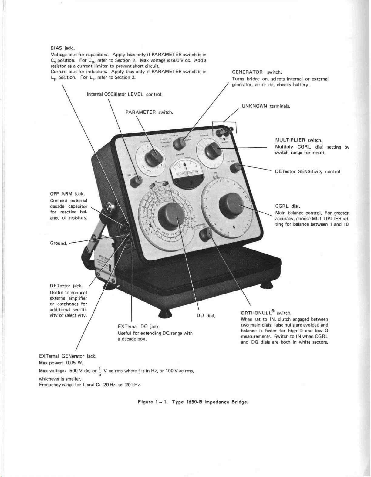
BIAS
jack.
Voltage bias for capacitors: Apply bias
Csposition.
resistor as a
Current bias for inductors: Apply bias only if PARAMETER switch
Lpposition. For
OPP ARM jack.
Connect external
decade capacitor
for reactive balance
of
For
Cp, refertoSection 2. Max voltageis600
current
limitertoprevent
ls,
refertoSection 2.
Internal OSCillator LEVEL control.
resistors.
only
if PARAMETER switchisin
short
circuit.
V dc. Add a
is
in
GENERATOR switch.
Turns
bridge on, selects internalorexternal
generator, acordc, checks battery.
UNKNOWN terminals.
MULTIPLIER switch.
Multiply CGRL dial setting
switch range
CGRL dial.
Main balance
accuracy, choose MULTIPLIER setting for balance between 1 and 10.
for
result.
control.
by
For greatest
Ground.
DETector jack.
Useful
to
external amplifier
or earphones for
additional sensitivityorselectivity.
EXTernal GENerator jack.
Max
power: 0.05
Max
voltage:
whicheverissmaller.
Frequency range
connect
W.
500
V dc;
for
LandC:20Hzto20kHz.
EXTernal DO jack.
Useful for extending DO range with
a decade box.
or
!..
V ac rms where fisin
5
Figure
Hz,or100
1 -1.Type
V ac rms,
1650-B
Impedance
ORTHONULLI'li switch.
When set
two
balance
measurements. SwitchtoIN
and DO dials are
to
main dials, false nulls are avoided and
IN, clutch engaged between
is
faster for high D
Bridge.
and
low 0
bothinwhite sectors.
when CGRL
Page 6
Section
1.1
DESCRIPTION.
The
I6S0-B
self-contained
cludes
resistance,
the
I-kHz
one-percent
highDandQaccuracy,amechanism
Q
CGRL
plete
and
the
sector.
beyond
coverofthe
adaptor
1.2
six
bridges
generators
measurements.
measurement,
dial,
portability,
carrying
CGRL
In
Extra
the
the
panel
dial
I-in.
OPENING
Impedance
impedance-measuring
for
the
measurementofcapacitance,
conductance,
and
C,G,R,
a
visual
andaconvenient
case.
slowly
torque
sector.
relay-rack
Type
I6S0-B
(paragraph
AND
and
detectors
Features
andLaccuracy
slow-motion
ac
and
The
slow-motion
and
mustbeapplied
mode1(F
is
1.6).
TILTING THE CABINET.
Bridge
inductance,
necessary
of
dc
null
effortlessly
igure
replaced
(Figure
system,
this
over
to
mechanism
indications,
tilting
mechanism
to
1-2),
witharelay-rack
1-1)isa
which
as
well
for
dc
bridge
include
all
ranges,
facilitate
mechanism
aboutaI-in.
move
the
the
captive
on
1-1
in-
as
and
low
the
com-
turns
dial
ntroduction
1.3
POWER
which
These
be
installed
facing
tected
shipmentbyan
and
the
a.
locked
b.
c.
d.
remove
e.
f.
g.
The
instrument
isinthe
SUPPLY.
The
Type
I6S0-B
slide
intoafiber
batteries,
the
open
from
lastce11.Toremove
Open
position.
Remove
Lift
Follow
the
Place
Replace
Replace
desired
with
leakage
the
the
instrument
the
disk.
the
supplied
the
positive
endofthe
and
insulating
instrument
the
two
directions
battery
the
instrumentinits
the
two
is
now
position
is
powered
tube
inside
with
the
instrument,
terminals
tube.
The
accidental
disk
inserted
the
disk,
proceedasfollows:
cabinet
cabinet
from
tube
backinits
cabinet
readytooperate
and
its
on
the
screws.
turned
and
screws
cabineL
cabinet.
by
four D
the
(center
batteries
discharge
between
placeitin
(Figure
battery
holder.
as
on.
cells,
instrument.
should
buttons)
are
pro-
during
the
cap
1-4).
cube,
and
soon
as
the
it
The
pedance
instrument.
to
any
convenient
to
give
the
best
The
same
slide
closed.
open
position
Whether
cover
forms a
tion
manual
kept
with
directions
Bridge
the
viewofthe
the
are
Once
most
instrument
pins
Thus,
with
the
convenient
and
instrument.
for
given
open,
angle.
comfortable
meter
maybelocked
that
are
the
instrument
the
cover
instrument
for
any
other
opening
on
the
The
and
used
storage
the
the
handle
instrument
angle
access
dials.
to
can
firmlyinplace.
is
open
place
test
Type
I6S0-B Im-
supportofthe
maybetilted
shouldbechosen
to
the
knobs
fully
openbythe
lock
the
instrument
be
carried
or
closed,
for
the
instruc-
data
that
should
and
in
the
the
be
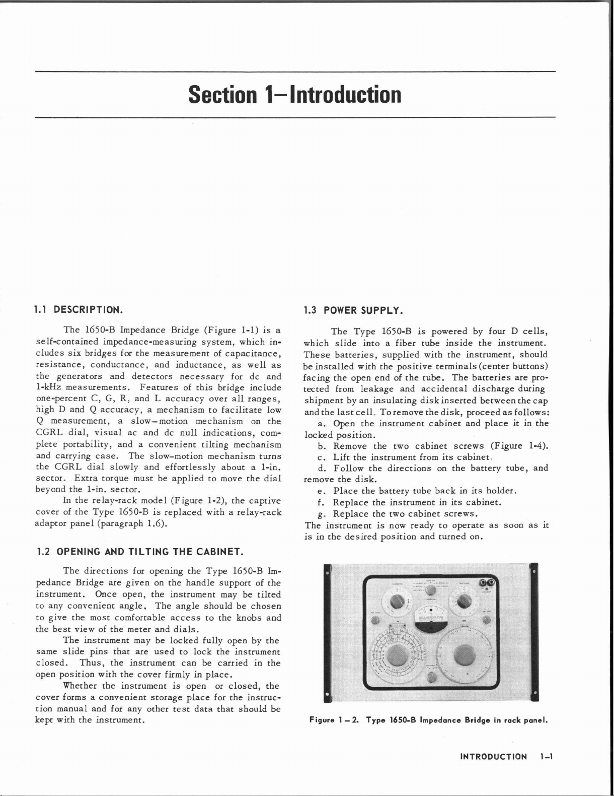
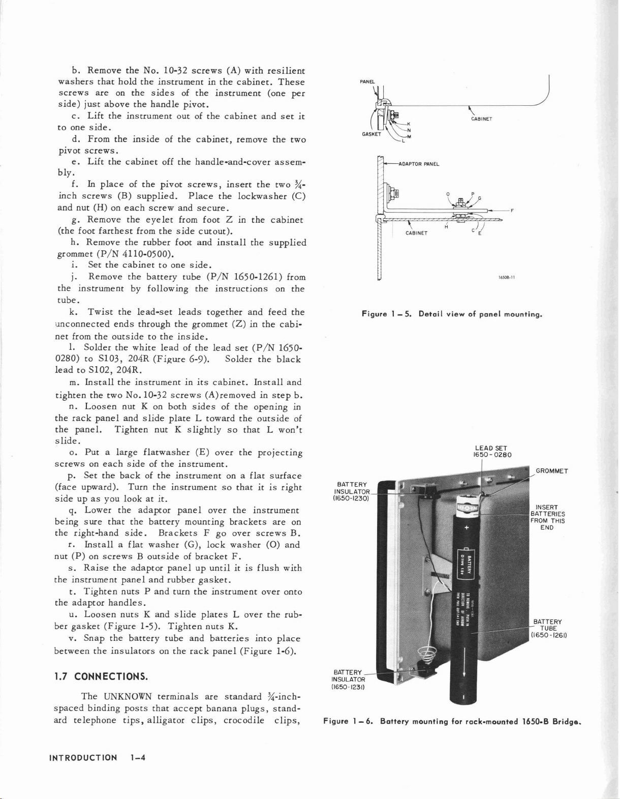
Figure 1 - 2. Type 1650-B Impedance Bridge in rack panel.
INTRODUCTION
1-1
Page 7
1.4
nitions
in
this
SYMBOLS,
The
following
are
used
instruction
ABBREVIATIONS,
symbols,
on
the
manual:
abbreviations,
panelofthe
AND
DEFINITIONS.
Type
and
1650-B
defi-
and
D
dissipation
factor
1
G
B
cot
e tan 8
Q
C
capacitance
external
bridge
paralle1c<ipacitance
series
standard
unknown
conductance
unknown
inductance
bridge
paralle
series
unknown
resistance
ratio
arm
(
----iE---
decade
residual
capacitance
capacitor
capacitance
(
-.JWV-
conductance
(
...rvYV"\-.
residual
lind
uctance
inductance
inductance
(
~),
resistance
capacitor
capacitance
(0.1
inductance
)
fJF)
),
the
inverseofresistance
)
the
real
partofan
impedance
PF
f
w
kD
M
MD
flF
mD
nF
pF
H
mH
R
power
factor
frequency
angular
ohm,
a
pedance
kilohm,1kD=1000
multiplying
quencies
megohm,1MD
microfarad,aunitofcapacitance
milliohm,
(or
mflF)
ImflF
(or
flflF)
1
flflF
henry,aunitofinductance
millihenry,
microhenry,
ground,
=-
frequency,
unit
factor
other
ImD = 1 x
nanofarad
=1 x
10-3flF
picofarad
=1 x
10-6flF
ImH
1
case
(chassis)
Z
of
resistance,
than
=1 x
= 1 x
J1H
=1 x
277
R
=
f
ohms
applied
toDandQat
1 kHz
106ohms
3
10-
ohm
(or
millimicrofarad),
(or
micromicrofarad),
3
10-
H
10-6H
reactance,
cos
or
e
Im-
fre-
InF
IpF
standard
CGRL
bridge
parallel
series
DQ
unknown
series
impedance
Z
Q
impedance
quality
for
10
rheostat
residual
resistance
resistance
rheostat
resistance
reactance,
factor
inductors
kD
resistor
resistance
resistance
resistance
the
X
=-=-
R
wL
S
R
S
imaginary
B
G
R
p
or
wL
p
parrofan
1
D
tan
1.5
SERIES
An
a
pure
frequency
of
resistance
will
mind
bridge
llsed
in
series
lent
circuits
for
series-parallel
Appendix.
impedance
resistance
by
be
results.
the
or a
parallel
AND
PARALLEL
thatisneitherapure
mayberepresented
eitheraseries
and
reactance.
invaluable
The
valuesofresistance
equivalent
combination
are
shown
conversion
COMPONENTS.
oraparallel
Keeping
for
properly
circuit
in
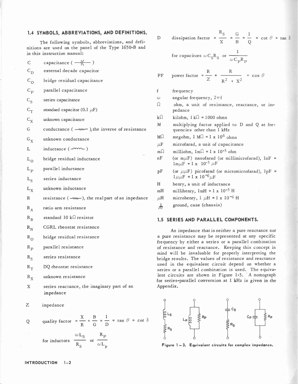
Figure
at
reactance
at
any
combination
this
concept
interpreting
and
depend
is
1 kHzisgiveninthe
on
used.
1-3..A
whether
The
nomograph
nor
specific
the
reactance
equiva-
in
a
lcs
Ls
L
cot
e
;)
R
s
Figure
p
1 -3.Equivalent
Rp
circuits
IRS
for
complex
Cp
impedance.
Rp
INTRODUCTION
1-2
Page 8
are
Q a
The
tabulated
relationships
below.
They
between
are
easily
RESISTANCE AND INDUCTANCE
jWLpR
p
R
+ jWL
p
1
__
=
o
=~
WL
p
the
p
circuit
derived.
elements
10-32
SCREWS
CAl
R
s
R
s
Z
=-
0
C
s
Q2
L
+ Q2
1
1
+ Q2
L
Q2
1
Rp;
+ Q2
1
WL
s
----.
- ,
Q
R
RESISTANCE AND
1
+--
R
s
jwC
s
1
Q
wRsC
2
(l
+ 0
) Cp;
1
----L
p
1 + 0
p
2
s
(l
R
p
=
QWL
p
---
jC£p
+---
R
p
+ Q2) R
p
CAPACITANCE
R
p
1
jC£p
s
02R
(B)
r
SCREWS
LEAD
SET
---------~--
1
+--
P
jC£p
2
+ 0
1
1
s
C
p
WRpC
1
p
1
+ 0
FLAT WASHER(M)
C
s
2
PLATE(L)
(J
I
(K~
2
R
s
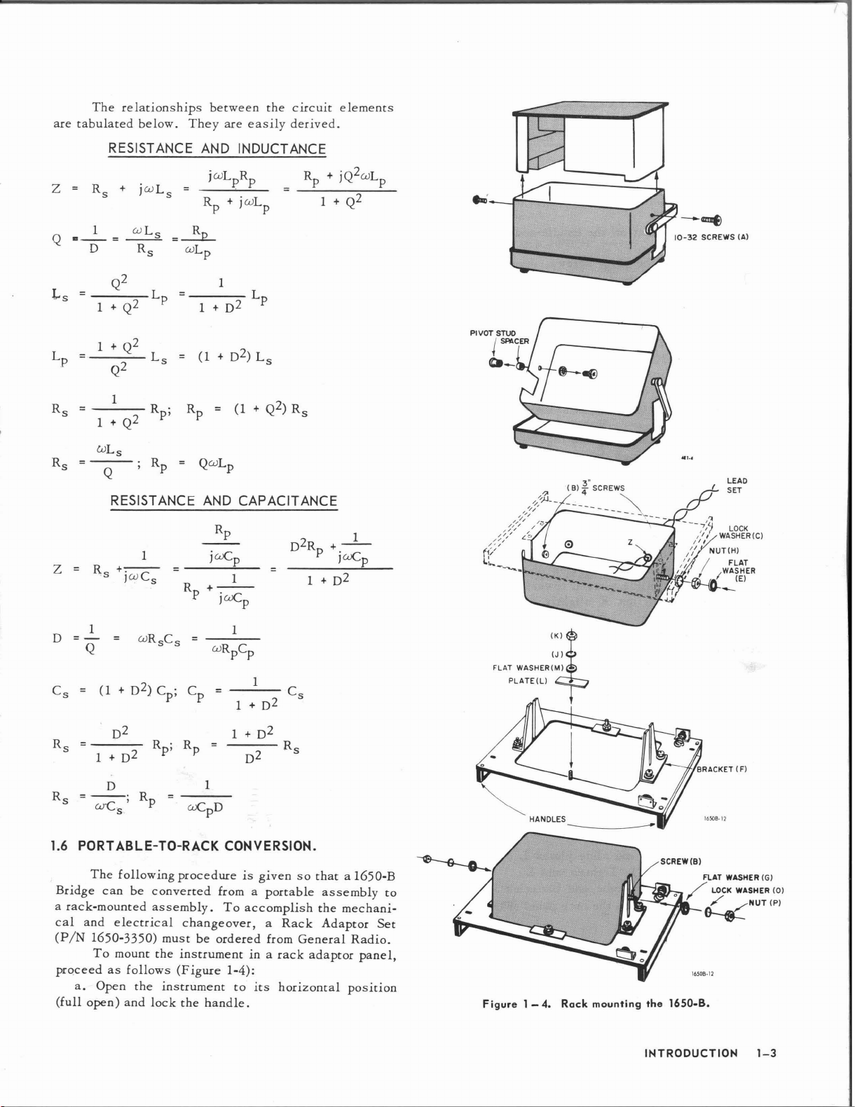
1.6
Bridge
a
rack-mounted
cal
(PIN
0
+ D2
1
PORT
ABLE-TO-RACK
The
following
can
be
and
electrical
1650-3350)
To
mount
prQceedasfollows
a.
Open
the
(full
open)
and
2
1
Rp;
R
p
+ D
=
2
0
1
CONVERSION.
procedureisgivensothat
converted
assembly.
mustbeordered
the
instrument
lock
from a
To
changeover,
instrument
(Figure
the
1-4):
handle.
portable
accomplish
a
from
in a
to
its
R
s
assembly
the
Rack
Adaptor
General
rack
adaptor
horizontal
a 1650-B
mechani-
Set
Radio.
panel,
position
~
HANDLES
16508-12
-------------
FLAT WASHER
/
to
LOCK
o
./
~
16508·12
Figure
1- 4.
Rack
mounting
the
1650.8.
INTRODUCTION
(Gl
WASHER (01
/NUT(Pl
1-3
Page 9
b.
washers
screws
side)
c.
to
one
d.
pivot
e.
Remove
just
Lift
side.
From
screws.
Lift
that
are
hold
on
above
the
the
the
the
No.
the
instrumentinthe
the
sides
the
handle
instrument
inside
cabinet
10-32
outofthe
of
the
off
the
bly.
f.
In
place
of
the
pivot
inch
screws
and
nut
g.
(the
foot
h.
grommet
1.
j.
the
instrument
Remove
(B)
(H)oneach
Remove
farthest
(PIN
4110-0500).
Set
the
cabinettoone
Remove
supplied.
the
from
the
the
by
screw
eyelet
the
rubber
battery
following
and
from
side
foot
tube.
k.
Twist
the
unconnected
net
from
the
1.
Solder
0280)toS103,
leadtoS102,
m.
Install
tighten
the
the
n.
rack
panel.
the
Loosen
panel
two
lead-set
ends
through
outsidetothe
the
white
204R
204R.
the
instrumentinits
No.
10-32
nutKon
and
slide
Tighten
leads
the
ins
leadofthe
(Figure
screws
both
plateLtoward
nutKslightly
slide.
o.
Putalarge
screws
(face
sideupas
being
the
nut
the
the
ber
between
on
each
p.
Set
the
upward).
you
q.
Lower
sure
that
right-hand
r.
Installaflat
(P)onscrewsBoutsideofbracket
s.
Raise
the
instrument
t.
Tighten
adaptor
u.
gasket
v.
Loosen
Snap
the
handles.
(Figure
the
insulators
flatwasher
sideofthe
backofthe
Turn
the
look
at
the
adaptor
the
battery
side.
washer
adaptor
panel
and
nutsPand
nutsKand
1-5).
battery
instrument.
instrument
instrument
it.
panel
Brackets
panel
rubber
turn
slide
Tighten
tube
on
the
screws
of
the
(A)
instrument
pivot.
cabinet
cabinet,
handle-and-cover
screws,
Place
insert
the
secure.
foot
2 m
cutout).
and
install
side.
tube
(PIN
the
instructions
together
grommet
ide.
lead
6-9).
Solder
cabinet.
(A)
removedinstep
sides
of
so
(E)
over
onaflat
so
over
mounting
F
go
(G),
lock
up
untilitis
gasket.
the
instrument
platesLover
nuts
and
batteries
rack
panel
with
cabinet.
and
remove
the
lockwasher
the
the
1650-1261)
and
(2)
in
set
(PIN
the
Install
the
opening
the
outside
thatLwon't
the
projecting
thatitis
the
instrument
brackets
over
screws
washer
F.
flush
over
K.
into
(Figure
resilient
These
(one
set
the
assem-
two
cabinet
supplied
on
feed
the
cabi-
1650-
black
surface
right
are
(0)
the
place
1-6).
per
two
(C)
from
the
the
and
in
on
B.
and
with
onto
rub-
b.
of
%-
PANEl..
it
CABINET
p
-~
16508-11
Figure
BATTERY
INSULATOR
(1650-1230)
1 -5.Detail
view
of
1650-
panel
LEAD
mounting.
SET
0280
GROMMET
INSERT
BATTERIES
FROM
THIS
END
BATTERY
TUBE
(1650-1261)
1.7 CONNECTIONS.
The
UNKNOWN
spaced
ard
INTRODUCTION
binding
telephone
posts
tips,
1-4
terminals
that
accept
alligator
are
clips,
standard
banana
crocodile
plugs,
%-inch-
stand-
clips,
BATTERY_
INSULATOR
(1650-1231)
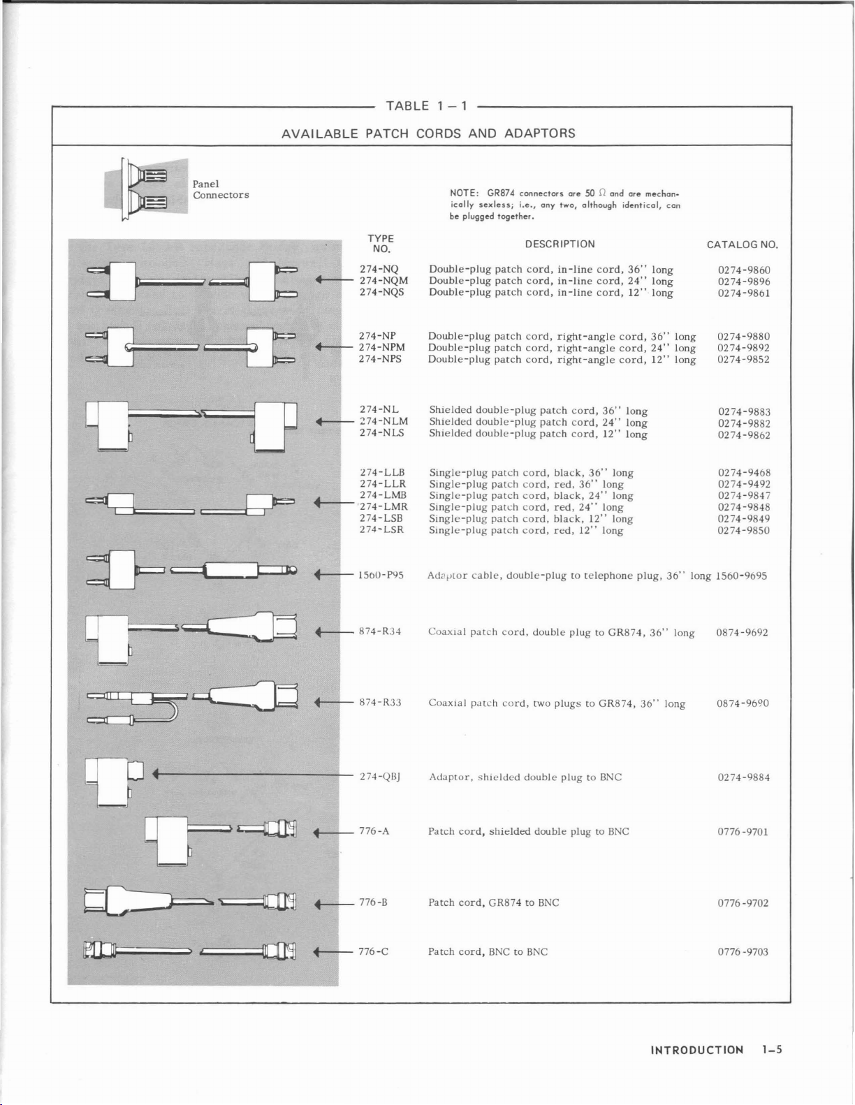
Figure
1 -6.Battery
mounting
for
rock-mounted
1650·B
Bridge.
Page 10
TABLE
1 - 1
Panel
Connectors
c:=Cdl;;;;;;;;;=,=c
=~
AVAILABLE
+---
+-+-
+---
f----'274-LMR
PATCH CORDS
TYPE
NO.
274-NQ
274-NQM
274-NQS
274-NP
274-NPM
274-NPS
274-NL
274-NLM
274-NLS
l74-LLB
274-LLR
274-LMB
274-LSB
274-LSR
Double-plug
Double-plug
Double-plug
Double-plug
Double-plug
Double-plug
Shielded
Shielded
Shielded
Single-plug
Single-plug
Single-plug
Single-plug
Single-plug
Single-plug
NOTE:
ically
be
plugged
AND
GR874
sexless;
together.
patch
patch
patch
patch
patch
patch
double-plug
double-plug
double-plug
patch
patch
patch
patch
patch
patch
ADAPTORS
connectors
Le.,
any
two,
DESCRIPTION
cord,
in-line
cord,
in-line
cord,
in-line
cord,
right-angle
cord,
right-angle
cord,
right-angle
patch
patch
patch
cord,
black,
cord,
red,
cord,
black,
cord,
red,
cord,
black,
cord,
red,
ore50D ond
although
cord,
cord,
cord,
cord,
36"
cord,
24"
cord,
12"
36"
36"
long
24"
24"
long
12"
12"
long
identical,
cord,
cord,
cord,
long
long
long
long
long
long
ore
36"
24"
12"
mechon-
can
long
long
long
36"
24"
12"
long
long
long
CATALOG
0274-9860
0274-9896
0274-9861
0274-9880
0274-9892
0274-9852
0274-9883
0274-9882
0274-9862
0274-9468
0274-9492
0274-9847
0274-9848
0274-9849
0274-9850
NO.
t--
f----r-
.~-----------"--
+----7- 776 -A
~776-B
+----7-
874-R34
874-R33
274-QI3J
776-C
Ad3fltor
Coaxial
Coaxial
Adaptor,
Patch
Patch
Patch
cable,
patch
patch
shielded
cord,
cord,
cord,
double-plugtotelephone
cord,
double
plugtoGR874,
cord,
two
plugstoGR874,
double
plugtoBNC
shielded
GR874toBNC
BNCtoBNC
double
plugtoBNC
plug,
36"
36"
36"
long
long
long
1560-9695
0874-9692
0874-9690
0274-9884
0776 -9701
0776 -9702
0776 -9703
INTRODUCTION
1-5
Page 11
spade
terminals
(F~ure
1-7).
The
two-terminal
No.
440.
The
a
single
or 2
banana
(PIN
and
EXT
DQ,
telephone
EXT
GEN,
plug
0274-9454
Standard
telephone tip
all
DET,
plug
G, and
such
or
wire
size
uptonumber
eleven
jacks
274-MB
and
BIAS
jacks
accept
such
as
the
Switchcraft
OPP
ARM
jacks
as
the
GR
Type
274-DBI
9455,
respectively).
Banana plug stabilized
Shoulder
PI
binding post body alligator clip
assuring contact even .
when nut
by
ug
enters Slender
is
loose. I s
i
Figure
1 -7.Methodsofconnection
a
accept
be
opp
necting
interconnections.
These
~
binding post only. 0
Table
I
4 posts.
to
the
are
Insulated
used
between
ARM
General
cables
1-1.
It
.
'd
InSI
e lac top
of
all binding
meosurement
spaced
%-inchoncenters
Double
the
EXT
andGterminals.
Radio
also
that
can
Some of
~I
Spade
with l4" throat all wire sizes
. k
will clamp
under nut.
terminals.
so
that
a GR
Plug
(PIN
0274-9875)
GEN
andGterminalsorthe
makesavarietyofintercon-
be
used
in
various
these
cables
terminal'
~
~
are
Clamps
up to
No.
without cutting.
11
shown
Type
can
system
in
INTRODUCTION
1-6
Page 12
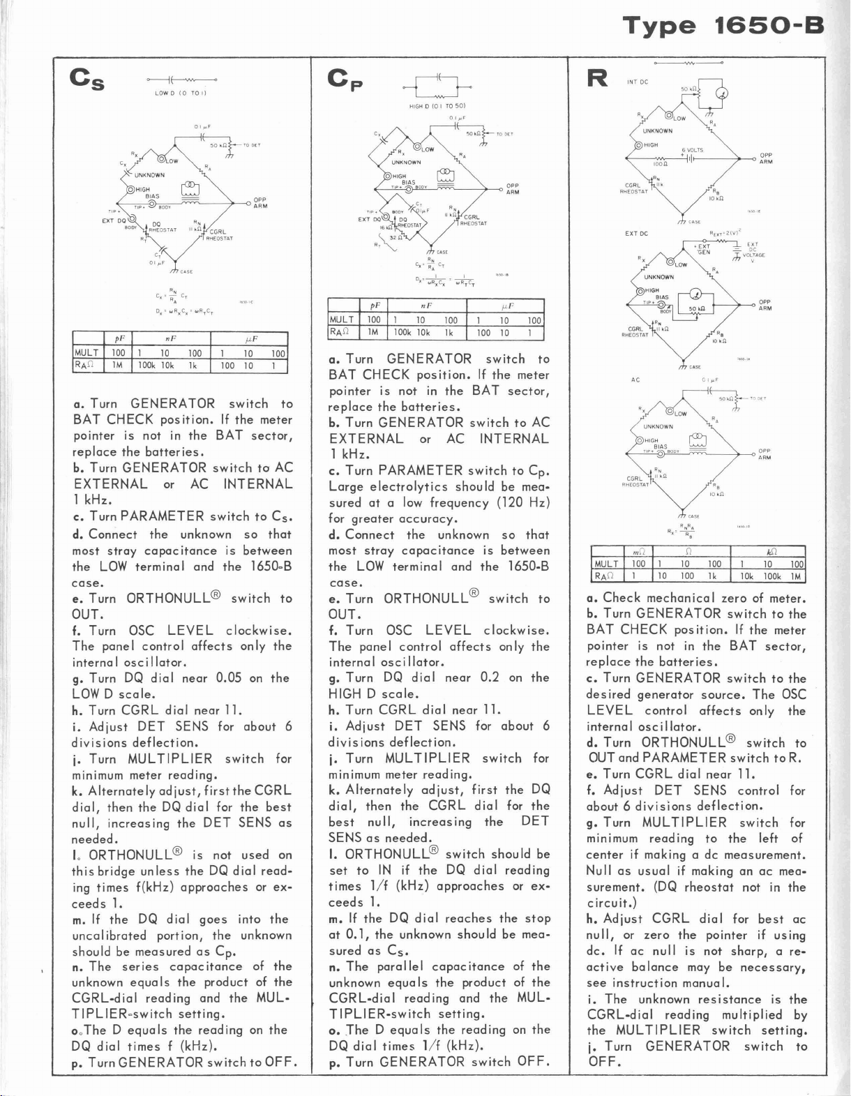
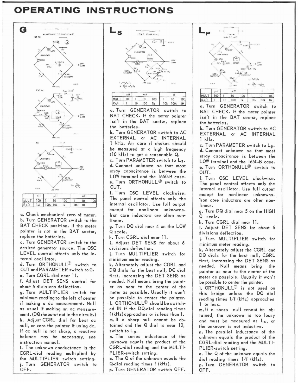
2.1
GEN
ERAL.
Figure
in
the
Type
balance
bridges
bridges
andQranges.
Q
and
highDvaluesisachieved
null@
balancing
and
dc
2-1
1650-B
equations.
and
series
are
usedtoprovide
Full
mechanism
measurements
SERIES
shows
Impedance
Hays
and
parallel
useofthese
may
LOW
(
o
CAPACITANCE
08
Section
the
six
bridge
Bridge,
and
Maxwell
capacitance
wide
coverage
wide
by
meansofan
(paragraph
be
made
with
C
s
D)
TO
I
RATIO
R
A
ARM
InTOIMol}
2-
circuits
as
wellasthe
inductance
comparison
over
ranges
5.4).
the
PARALLEL
Basic
used
the
D
at
low
Ortho-
Both
ac
bridge,
C
p
HIGH
(
01TO50
CAPACITANCE
Measurements
which
tion
schematics
the
bias,
as
Orthonull
basic
chart.
D)
hasamagnitude
The
next
needed
for
include
userinmaking
etc.
The
those
definedinSection
usage,
measurement
two
pages
making
all
special
symbols
detector
responsive
relevent
practice
RESISTANCE
concisely
basic
bridge
measurements
on
the
diagrams
1. A
sensitivity,
follows
R
detector.
state
the
measurements.
terminalstoaid
that
are
short
discussion
etc
relating
the
instruction
informa-
The
require
the
same
of
to
CONWCTANCE
R
/0TO/ MtI(/
R
N
"CGRL"
0-11
It
A
Figure
C 0
x
D 0
x
SERIES
Lx
08
2 -1.Bridge
R
N
RAC
__
1_:
OJRxC
L
LOW
(
.02
TO 10'
INDUCTANCE
circuits
r
_1_
OJRrC
x
S
r
0
'.
RATIO
ARM
InTOIMOI}
usedinimpedance
L
p
(Hj~~
0)
PARALLEL
R
A
bridge.
INDUCTANCE
16508-14
BASIC MEASUREMENTS 2-1
Page 13
Type
1650-8
LOW 0(0TO
I)
01
"F
~"'"
'.
R,
lI.n
CGRL
R,
c)('~
0.'
pF
MULT
100
1
RAO
1M
a.
Turn
BAT
CHECK
pointer
replace
b.
Turn
EXTERNAL
1
kHz.
c.
Turn
d.
Connect
most
stray
the
LOW
10
lOOk
10k
GENERATOR
position.Ifthe
is
not
the
batteries.
GENERATOR
m AC
PARAMETER
the
capac
terminal
case.
e.
Turn
ORTHONULL@
OUT.
f.
Turn
OSC
The
panel
control
internal
g.
oscillator.
Turn DQ dia I
LOWDscale.
h.
Turn
CGRL
i.
Adjust
divisions
j.
Turn
minimum
k.
Alternately
dial,
null,
DET
deflection.
MULTIPLIER
meter
then
the
increasing
adjust,
DQ
needed.
L
ORTHONULL@
this
bridge
ing
times
ceeds
m.Ifthe
uncaIibrated
unless
f(kHz)
1.
DQ
portion,
shouldbemeasuredasCpo
n.
The
series
unknown
CGRL-dial
T I
PLIER-switch
ooThe D
DQ
p.
Turn
equaIsthe
equals
dial
timesf(kHz).
GENERATOR
reading
RHEOSTAT
R,
CT
wR.C.
wArC
r
nF
100
1k
in
the
switchtoAC
switchtoCs•
unknown
itance
and
LEVEL
affects
near
dial
near
SENS
reading.
first
dial
the
DET
is
not
the
DQ
approaches
dial
goes
the
capacitance
productofthe
and
setting.
the
reading
switchtoOFF.
BAT
0.05
for
for
I-'F
1
10
100
100
10
1
switch
meter
sector,
INTERNAL
so
that
is
between
the
1650-B
switch
clockwise.
only
on
the
1l.
about
switch
the
CGRL
the
best
SENS
used
dial
read-
or
into
the
unknown
of
the
MUL-
on
the
to
to
the
for
as
on
ex-
the
R
HIGH 0(0ITO50)
o
II'F
~w,,,
R.
R,
IIonCGRL
RHEOSTAT
CASE
e,,;'~CT
D)(·~'
...
RITCT
pF
MULT
100
RAO
1M
a.
Turn
BAT
CHECK
pointer
replace
b.
the
Turn
GENERATOR
EXTERNAL
1
kHz.
c.
Turn
PARAMETER
Large
electrolytics
sured
at
for
greater
d.
Connect
most
stray
the
LOW
case.
e.
Turn
OUT.
f.
Turn
The
paneIcontrol
internal
g.
Turn
HIGH D
h.
Turn
CGRL
i.
6
Adjust
divisions
j.
Turn
minimum
k.
Alternately
dial,
then
best
null,
SENSasneeded.
I.
ORTHONULL@
set
to
INifthe
times
lIf
ceeds
1.
m.
If
the
at
0.1,
the
sured
as
n.
The
parallel
unknown
CGRL-dial
TIPLIER-switch
o• .The D
DQ
dial
p.
Turn
nF
1
10
10k
100
lk
lOOk
GENERATOR
position.Ifthe
IS
notinthe
batteries.
m AC
should
a low
ORTHONULL@
OSC
oscillator.
DQ
scale.
MULTIPLIER
meter
Cs•
equaIsthe
times
GENERATOR
frequency
accuracy.
the
unknown
capacitance
terminal
LEVEL
dial
dial
DET
SENS
deflection.
reading.
adjust,
the
CGRL
increasing
(kHz)
approaches
DQ
dial
unknown
capacitance
reading
setting.
equaIsthe
lIf
and
affectsonIy
near
near
switch
DQ
reaches
shouIdbe
(kHz).
I-'F
1
10
100
100
10
1
switch
meter
BAT
sector,
switchtoAC
INTERNAL
switchtoCpo
be
mea-
(120
Hz)
so
that
is
between
the
1650-B
switch
clockwise.
the
0.2
on
the
11.
for
about
switch
first
the
dial
for
the
the
DET
should
dial
reading
or
ex-
the
stop
mea-
of
productofthe
and
the
MUL-
read
ing on
switch
OFF.
to
to
for
DQ
be
the
the
a.
b.
BAT
pointer
replace
c.
desired
LEVEL
6
internal
d.
OUT
e.
f.
about6divisions
g.
minimum
centerifmakingadc
Nullasusual
surement.
circuit.)
h.
null,
dc.
active
see
i.
CGRL-dial
the
j.
OFF.
o HIGH
loon +
R,
CGRL
Ilk
RHEOSTAT
EXT
DC
R,
AC
R,
UNKNOWN
R,
CGRL
lI.n
RHEOSTAT
1
10
Check
Turn
mechanical
GENERATOR
CHECK
is
notinthe
the
Turn
GENERATOR
generator
control
oscillator.
Turn
ORTHONULL@
and
PARAMETER
Turn
CGRL
Adjust
Turn
DET
MULTIPLIER
reading
(DQ
Adjust
CGRL
or
zero
If
ac
null
balance
instruct
The
unknown
MULTIPLIER
Turn
GENERATOR
6YOLTS
Ilt---~-----<>
R,
IOkn
"T
-=-
DC
;h
VOLTAGE
10k!}
,
R.
R,
°
LOW
°lOW
10
100
o
II'F
100
lk
zeroofmeter.
switchtothe
position.Ifthe
BAT
batteries.
switchtothe
source.
affects
The
only
switch
switchtoR.
dial
near
11.
SENS
control
deflection.
switch
to
the
measurement.
if makinganac
ion
rheostat
dial
the
is
may
manua
for
pointer
not
sharp,are-
be
I.
not in
necessary,
resistance
reading
multiplied
switch
switch
~~:
meter
sector,
OSC
left
mea-
best
if
using
is
setting.
the
to
for
for
of
the
ac
the
by
to
Page 14
OPERATING
INSTRUCTIONS
G
Q.
Check
b.
Turn
BAT
po
interisnot
replace
c.
Turn
desired
LEVEL
ternal
d.
Turn
OUT and
e.
Turn
f.
Adjust
RESISTANCE
mechan
GENERATOR
CHECK
the
batteries.
GENERATOR
generator
control
osci
lIator.
ORTHONULL@
PARAMETER
CGRL
DET
about6divisions
g.
Turn
MULTIPLIER
minimum
if making a
as
ment.
h.
null,orzero
If
balance
instruction
i.
CGRL-dial
the
j.
readingtothe
usual
if making
(DQ
rheostat
Adjust
ac
CGRL
null is not
may be
manual.
The
unknown
MULTIPLIER
Turn
GENERATOR
dc
the
reading
OFF.
(In
TO
IOOOtol!l)
icaIzeroofmeter.
switchtothe
position.Ifthe
in
the
BAT
switchtothe
source.
affects
The
only
switch
switch
diaInear
SENS
1l.
control
deflection.
switch
leftofcenter
measurement.
an
ac
measure-
notinthe
dial
for
circuit.)
best
pointerifusing
sharp,areactive
necessary,
conductance
multiplied
switch
setting.
switch
meter
sector,
OSC
the
in-
toG.
for
for
Null
ac
dc,
see
is
the
by
HIGH 0
(I-CD)
O'"~'O'"
".
mil
MUL
T 1
RAIl
o. Turn
BAT
CHECK.Ifthe
isn't
in
the
batteries.
b. Turn
GENERATOR
EXTERNAL
1
kHz.
be
measured
(10kHz)
c.
Turn
PARAMETER
d.
Connect
stray
capacitance
LOW
terminal
e.
Turn
OUT.
f.Turn
The
panel
internal
except
Iron
core
linear.
g.
Turn DQ
Q
scale.
h.
Turn
CGRL
i.
Adjust
divisions
j.
Turn
minimum meter
to
k.
Alternately
dials
DQ
first,
increasing
needed.NuII
er
as
near
meterasposs
be
possible
I. ORTHONULL@
ed
INifthe
f (kHz)
m.
tained
approachesoris
If
a
and
switchtoLp•
The
n.
series
unknown
CGRL-dial
PLIER-switch
o.
The
Q of
to
Q-dial
p.
reading
Turn
GENERATOR
10
100
BAT
100
lk
meter
sector,
switch
pointer
replace
10
GENERATOR
the
switchtoAC
m AC
Air
core
atahigh
to
getareasonab
INTERNAL
rf <:hokes
frequency
Ie Q.
switchtoLs.
unknown
and
the
so
is
that
between
1650-B
ORTHONULL@switch
OSC
LEVEL
control
oscillator.
for
nonlinear
inductors
dial
dial
DET
near
SENS for
affects
Use
are
4 on
near
clockwise.
only
full
unknowns.
often
the
1l.
about
deflection.
MULTIPLIER
switch
reading.
for
adjust
the
means
to
ib Ie.
to
best
the
the
Usua
center
the
null,
DET
bring
center
CGRL
the
lIy it
the
DQ
SENS
pointer.
shouldbeswitch-
DQ-dial
sharp
theQdial
equaIsthe
reading
reading
null
cannot
inductance
productofthe
and
less
is
the
than
be ob-
near
of
MUL
setting.
the
unknown
times
equals
f (kHz).
switch
should
most
the
case.
the
output
non-
LOW
for
and
dial
point-
of
the
won't
times
1.
10,
the
TI-
the
OFF.
as
o.
Turn
to
BAT
CHECK.Ifthe
isn't
in
the
batteries.
b.
Turn
GENERATOR
EXTERNAL
the
BAT
m AC INTERNAL
GENERATOR
switch
meter
pointer
sector,
replace
switchtoAC
to
1 kHz.
c.
Turn
d.
Connect
stray
LOW
e.
Turn
PARAMETER
unknown
capac
itonce
terminal
and
ORTHONULL@
switchtoLp•
so
that
is
between
the
1650-B
switch
most
the
case.
to
OUT.
to
f. Turn OSC
The
panel
internal
except
1ron
oscillator.
for
core
LEVEL
control
nonlinear
inductors
affects
Use
are
clockwise.
only
the
full
output
unknowns.
often
non-
linear.
g.
Turn DQ
scale.
Q
h. Turn
i.
Adjust
divisions
j.
6
Turn
minimum
k.
Alternately
dials
DQ
first,
needed.
pointerasneartothe
meteraspossible.
dial
CGRL
DET
deflection.
MULTIPLIER
meter
for
the
increasing
Null
near
5 on
dial
near
SENS for
reading.
adjust
the
best
the
DET
means
centerofthe
Usuallyitwon't
the
1l.
switch
CGRL
null,
SENS
bring
HIGH
about
CGRL
6
for
and
as
the
be possible to center the pointer.
is
not
used
DQ
be
Ls, or
of
MUL
on
dial
ob-
lossy
the
TI-
to
I. ORTHONULL@
this
bridge
read
ing
1 or
less.
m.Ifa
tained,
and
must
the
unknown is not
n.
The
unknown
CGRL-dial
PLiER-switch
o.
TheQof
dial
reading
p. Turn
unless
times
lIf
sharp
the
unknown
be
measured
parallel
equals
reading
setting.
the
times
GENERATOR
the
(kHz)
approaches
nuIIcannot
is
inductive.
inductance
the
productofthe
and
the
unknown
lIf
(kHz).
too
as
equaIsthe
switch
OFF.
Page 15
2.2 DC AND
With
ances
may
upto100kn.
shouldbeused
tivity
limits
meter may be
by
pluggingitinto
AC
SENSITIVITY.
the
be
internal
easily
Above
6-volt
madeupto
100knahigher
(paragraph
the
accuracyto±lOmn. A more
placed
in
series
the BIAS
bridge.
A 100-.0
supply
The
limits
unknown
external
when
the
The
bridge by
no
danger
At
I-kHzacmeasurements
most
resistors,
I-kHz and dc
resistor
the
current
isinseries
dc,
so
that
CGRL
range
dialisat
maximum power
the
internal
of
injuring
extremes
the
values
in
the
supplyis0.09W;
components
to
difference
is
negligible.
TABLE
MAXIMUMDCBRIDGE VOLTAGE
AND CURRENT
supply,
3.2).
jack
series
in
the
with
unknown
zero.
that
it
is
often
increase
21
-
one-percent
10kn
and
with
Below
with
on the
with
external
In,
the
the
voltage
the
sensitive
internal
side
internal6-V
sensi-
meter
of
unknownto60
the
CGRL
rheostat
currentisgreatest
canbeappliedtothe
thus
there
ratedatO.IW
or more.
desirabletomake
sensitivity.
between
the
measured
balcare
the
rnA.
For
for
is
An
external
1232,
is
very
at
frequencies
between
case.
a
convenient
2.3
the
The
screw
DC
VOLTAGE AND CURRENT LIMITS.
Bridge
tect
ponent
able
to
protect
maximum
test
voltages
Unless
test
voltageisdesired,asupplyofabout
a 90-V
battery),
tuned
desirable
other
than
LOW
UNKNOWN
near
the
ground
point.
voltages
WARNING
must
the bridge and
from
damage.
to
limit
the
currentto5
the
operator
voltage
voltages
the
are
utmost
with
described
and some
about25kn
null
when making
1kHz. It may be
terminal
UNKNOWN
be
the
limit,
in
sensitivity
TABLE 2-2
EIA STANDARD TEST VOLTAGES
(RS 196 FIXED-FILM RESISTORS
REC 117
LOW-POWER
WIRE-WOUND RESISTORS)
detector,
measurements
and
binding
limited
unknown com-
Itisalso
rnAorless
from
injury.
standard
military
below.
in
series,
such
connected
the 1650-B
post
to
pro-
advis-
The
EIA
test
or a
standard
100 V
is
as
(e.g.,
recom-
the
is
Range
Full Scale
1.0
10.0
100.0
kn
1
kn
10
100
kn
lMn
Range
Multiplier
100mn
HI
10.0
100.0
1
kn
10
kn
100
kn
E
71
71
71
71
71
223
500
Max
V
V
V
V
V
V
V
* Itispreferabletolimit currenttoaVOid
ortoreduce voltageto10
hazard
V.
Resistance Range
2.7 -
99.0
-999.0
100
10
9999.0
99
-
kn
1000 -
100knup
1*
Max
100
mA
100 mA
71
mA
22
mA
14.1
14.1
14.1
shock
rnA
rnA
mA
Resistance Bridge Mult EIA
Range
less
than
10.0
10-99.0
100 -
999.0
1000-9999.0
10-99
100kn
*
kn
up
REC
117 applies only upto9999.0.
At
EXT GEN terminals.
Range
1.0
10.0
100.0
1
10
100
kn
kn
kn
** Maximum allowance bridge voltage will
test
voltage.
T E
ABL
2-3
EIA STANDARD TEST VOLTAGES
(RS 172 - FIXED COMPOSITION HESISTORS)
Bridge Mult Range
1.0
10.0
100.0
1
kn
10
kn
100kn
EIA Test
Voltage Range
0.5 - 1 V
0.5
- 1 V
2.5
- 3 V
-lOV
8
24
-30
V
- 100 V
80
Test Voltage
10
30
100 V
Bridge*
Voltage
**
-71V***
50
27.5-33V
16 -20V
26.4-33
- 100 V
80
Max
0.3V
1 V
3
not
V
V
V
V
give
maximum
Max
Voltage
**
**
101
Bridge
33V
20
33
I-
V
V
V
BASIC MEASUREMENTS
at
EXT GEN terminals
*
** cannot get required bridge voltage
***
limitedto71
2-4
V by bridge
Page 16
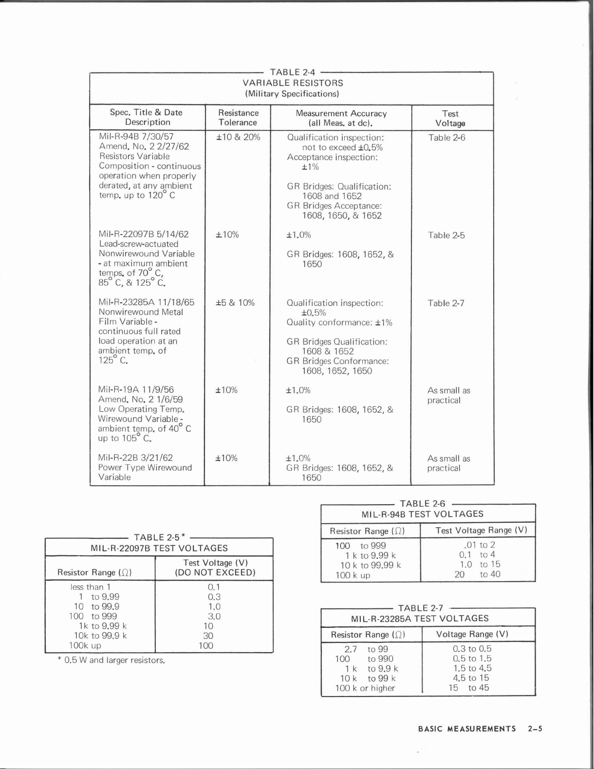
Spec.
Title
7/30/57
No.2
to
& Date
2/27/62
120° C
Description
Mil-R-94B
Amend.
Resistors Variable
Composition - continuous
operation when properly
derated, at any ambient
temp. up
VARIABLE
(Military
Resistance
Tolerance
±1O&20%
TABLE
2-4
RESISTORS
Specifications)
Measurement Accuracy
Meas.
(all
Qualification inspection: Table 2-6
not
Acceptance inspection:
±1%
GR
Bridges: Qualification:
1608
GR Bridges Acceptance:
1608, 1650,
at de).
to exceed ±0.5%
and
1652
& 1652
Test
Voltage
Resistor
less
1
10
100
1k
10k
lOOk up
* 0.5
Wand
70°
full
11/9/56
No.2
Variable-
C.
3/21/62
TABLE
5/14/62
C,
C.
11/18/65
rated
an
of
1/6/59
of
40° C
*
2-5
VOLTAGES
(DO NOT EXCEED)
Mil-R-22097B
Lead-screw-actuated
Nonwirewound Variable
- at maximum ambient
85°
continuous
ambient temp.
Mil-R-19A
Amend.
Wirewound
ambient temp.
up
Mil-R-22B
Power Type Wirewound
Variable
MIL-R-22097B TEST
Range
than 1
to
to
to
to
to
of
temps.
C,
& 125°
Mil-R-23285A
Nonwirewound Metal
Variable-
Film
load operation at
C.
125°
Low Operating Temp.
to
105°
(f2)
9.99
99.9 1.0
999
9.99 k
99.9 k
larger resistors.
±1O%
±5&10%
±1O%
±1O%
Test Voltage (V)
0.1
0.3
3.0
10
30
100
±1.0%
GR Bridges: 1608, 1652,
1650
Qualification inspection:
±0.5%
Quality conformance: ±1%
GR
Bridges Qualification:
1608 & 1652
GR Bridges Conformance:
1608, 1652, 1650
±1.0%
GR Bridges: 1608, 1652,
1650
±1.0%
GR Bridges: 1608, 1652,
1650
MIL-R-94B TEST
Resistor
Resistor
Range
to
100
10 k
100 k up
100
10k
100 korhigher
999
to
9.99 k
1 k
to
99.99 k
MI L·R-23285A TEST
Range
to
to
to
to
99
990
9.9 k
99 k
2.7
1 k
Table 2-5
&
Table 2-7
As
small
practical
&
& practical
As small
TABLE
(m
TABLE
((2)
2-6
VOLTAGES
Test Voltage
2-7
VOLTAGES
Voltage
15
as
as
.01to2
to
0.1
to
1.0
to
20
Range
0.3
to
0.5
0.5to1.5
1.5
to
4.5
4.5
to
15
to
45
Range
4
15
40
(V)
(V)
BASIC
MEASUREMENTS
2-5
Page 17
mended.
0.1
all
a
supply
curacy.
desirable
that
various
appliedtothe
2-1.
prevent
unknown,
toavalue
The
W,
which
resistors,
permits
For
resistance
for
the
maximum
typesofresistors
The
maximum
Careful
damagetothe
Because
itisadvisable
less
available
is
and
good
bridge
observation
the
than
component.
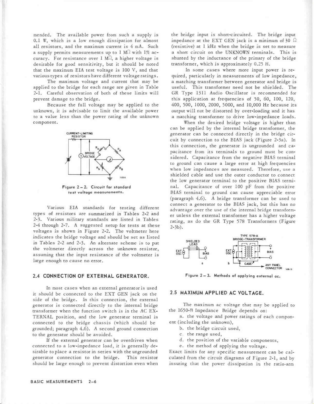
CURRENT-LIMITING
RESISTOR
Figure
test
Various
types
of
2-3.
Various
2-4
through
voltages
is
indicates
in
Tables
the
voltmeter
assuming
large
enoughtocausenoerror.
2.4
CONNECTION OF
EIA
resistors
military
2-7.
showninFigure
the
bridge
2-2
and
directly
that
the
power
a low
the
enough
maximum
measurements
over1MD,ahigher
sensitivity,
EIA
test
have
voltage
for
each
of
bridge.
full
voltage
to
the
power
2 - 2.
Circuit
voltage
measurements.
standards
are
summarized
standards
A
suggested
voltage
2-3.
An
across
input
resistance
EXTERNAL
from
suchasupply
dissipation
currentis4
upto1
MD
with
butitshould
voltage
different
and
current
range
is
100 V,
voltage
that
are
giveninTable
bothofthese
maybeapplied
limit
the
available
rating
for
setup
2-2.
and
shouldbesetaslisted
alternate
the
standard
for
are
The
of
testing
in-
Tables
listed
for
tests
voltmeter
scheme
unknown
of
the
the
voltmeter
GENERATOR.
for
almost
mAo
1%
voltage
be
and
ratings.
may
limits
unknown
different
2-2
in
Tables
at
is
resistor,
Such
ac-
noted
that
be
will
to
the
power
and
these
here
to
put
the
is
bridge
impedanceatthe
(resistive)
a
short
is
shunted
transformer,
quired,
a
matching
useful.
GR
Type
this
400,
output
a
matching
canbeapplied
generator
cuit
by
this
connection,
pacitance
sidered.
to
ground
when
shielded
the
low
nal.
BIAS
(paragraph
connectagenerator
advantage
er
unless
rating,
inputISshort-circuited.
EXT
GEN
at1kHz
circuit
by
the
when
on
the
inductance
the
UNKNOWN
of
whichisapproximately
In
some
cases
where
particularlyinmeasurements
transformer
This
1311
application
500,
1000,
will
notbedistorted
transformer
When
the
can
connection
from
Capacitance
can
low
impedances
cable
generator
Capacitance
terminal
4.6).
over
the
as
do
transformer
Audio
2000,
desired
by
be
the
its
causealarge
and
to
the
external
the
between
need
Oscillator
at
frequencies
5000,
to
drive
bridge
the
internal
connected
to
the
BIAS
generator
terminals
from
the
are
measured.
use
the
outer
terminaltothe
of
over
ground
A
bridge
to
the
can
transformer
BIAS
useofthe
transformer
GR
Type
The
bridge
input
jackisa minimumof30 D
bridgeissettomeasure
terminals.
the
primaryofthe
0.25
more
input
of
generator
not
be
is
of
50,
and
10,000
by
over-loading
low-impedance
voltage
bridge
directly
to
jack
is
ungrounded
ground
in
(Figure
negative
errorathigh
low
shielded.
recommended
60,
Hz
is
transformer,
the
BIAS
Therefore,
This
bridge
H.
powerisre-
impedance,
and
bridge
The
100,
120,
because
andithas
loads.
higher
than
the
bridge
cir-
2-3a).
and
must
be
con-
terminal
frequencies
use
conductortoconnect
100
cause
internal
578
positive
pF
jack,
hasahigher
Transformers
BIAS
from
the
appreciable
can
be
but
this
bridge
termi-
positive
error
used
has
transform-
voltage
(Figure
is
is
for
its
In
ca-
a
to
no
2-3b).
SHIELDED
LEAD
is
OSCLJ
Figure
EXT~
AS
L6
2 -3.Me.thodsofapplying
EXT
OSC
external
16Q8.18
ac.
In
most
cases
whenanexternal
it
should
side
generator
transformer
TERNAL
connected
grounded;
to
the
connected
be
connected
of
the
bridge.
is
connected
when
position,
to
the
paragraph
generator
If
the
should
external
toalow-impedance
the
bridge
to
In
this
directly
function
and
the
4.6).
be
generator
the
low
chassis
A
second
avoided.
sirabletoplacearesistorinseries
generator
shouldbelarge
BASIC
connection
enoughtoprevent
MEASUREMENTS
to
the
2-6
generatorisused
EXT
GEN
jack
connection,
to
switchisin
generator
(which
the
ground
the
internal
the
terminal
should
connection
canbeoverdriven
load,
itisgenerally
with
the
ungrounded
bridge.
This
distortion
external
AC
resistor
even
on
the
bridge
EX-
when
when
be
de-
2.5 MAXIMUM
The
the
1650-B
a.
is
ent
Exact
culated
insuring
the
(including
b.
the
c
the
d.
the
e.
the
limits
from
APPLIED
maximumacvoltage
Impedance
voltage
the
bridge
range
Bridge
and
power
unknown),
circuit
used,
positionofthe
methodofapplying
for
any
specific
the
that
circuit
the
diagramsofFigure
power
AC
VOL
that
depends
ratingsofeach
used,
variable
the
measurement
dissipation
TAGE.
maybeapplied
on:
components,
voltage.
can
2-1,
in
the
compon-
be
cal-
and
ratio-arm
to
by
Page 18
resistors
a maximum
avoid
any
resultinan
A much
into
the
can
be
rating
power
shouldbereduced
is
the
simplest
a
value
tor
voltage
ponent
.
The
ther
limitonthe
E a
=J...
m x 5
whicheyer
step-down
to
the
primary,
applied
2
...E:....
- 20.0
2
supply.
and
the
rheostats
voltage
is
adjustments
overload.
simpler
bridgeto0.5Wso
damaged
of
the
of R
input
under
unknown
way
2
=..E:..
,
4P
andPthe
transformer
to
where
power
voltage
volts(fin
is
ratio
Hz),
smaller.
andanequivalent
of 20 .0.
to
the
bridge
should
be
placedInseries
is
less
than
applied,
of
approach
any
is
the
panel
that
conditions.
less
care
is
no
than
must
controls
to
bridge
0.5
accordingly.Aseries
limit
the
power.
Eisthe
open-c
ratingofthe
imposes
appliedtothe
or 100
This
transformer
the
EXT
volts,
resistance,
Therefore,
to
0.5
to
W,aseries
with
0.5
W.Ifsuch
be
that
limit
the
components
If
the
W,
the
It
should
ircuit
unknown
following
GEN
hasa3-to-1
referred
limit
the
resistor
the
external
taken
would
power
power
input
resistor
have
genera-
com-
fur-
jack:
power
c.
Set
the
CGRL
dial
upscale
to
of
d.
Make
the
e.
DQ
dial,
mechanism,
than1at
toalower
f.
then
the
meter
reading
When
give
several
To
find
a
wide
range
Often
and
itisdesirable
urement.
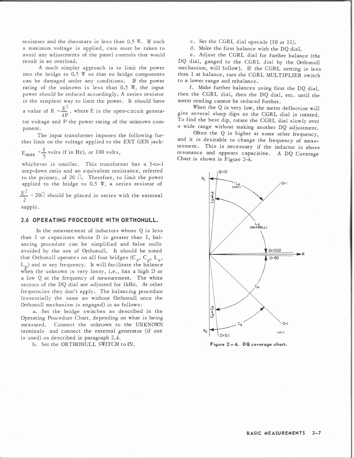
resonance
Adjust
Make
the
the
ganged
will
balance,
range
and
further
CGRL
dial,
cannotbereduced
theQis
sharp
best
dip,
without
theQis
This
is
and
appears
ChartisshowninF
first
CGRL
to
the
follow).
turn
rebalance.
balances
then
very
dips
rotate
higher
to
necessary
igure
L
(HAY)
balance
dial
CGRL
If
the
CGRL
the
low,
as
the
the
making
change
capacitive.
2~4.
p
with
for
dial
the
CGRL
MULTIPLIER
using
DQ
further.
the
meter
CGRL
CGRL
another
at
some
the
frequency
if
the
(10or11).
the
DQ
dial.
further
by
balance
the
setting
first
the
dial,
etc.
deflection
dialisrotated.
dial
slowly
DQ
adjustment.
other
inductor
A
DQ
Q=I
(the
Orthonull
is
less
switch
DQ
dial,
until
the
will
over
frequency,
of
meas-
is
above
Coverage
2.6
OPERATING
In
the
measurement
than
1 or
capacirors
ancing
avoided
that
Lp)
when
a low
procedure
by
the
Orthonull
andatany
the
unknownISvery
Q
at
the
sectorsofthe
frequencies
they
(essentially
Orthonull
Operating
mechanismisengaged)isas
a.
Set
the
Procedure
measured.
terminals
IS
used)asdescribed
and
b.
Set
the
PROCEDURE
can
use
of
operates
frequency.
frequency
DQ
dial
don't
the
same
bridge
Chart,
Connect
connect
ORTHONULL
of
whose
be
simplified
Orthonull.
on
all
It
lossy,
of
are
adjusted
apply.
as
without
switches
the
unknown
the
in
paragraph
WITH
inductors
Disgreater
It
four
bridges
will
~ac
ilitate
I.e.,
measurement.
for
The
balancing
Orthonull
as
described
depending
to
external
generator
2.4.
SWITCHtoIN.
ORTHONULL.
whose
and
should
Q
than
false
be
(C
, C , L ,
s p s
the.
is
1,
nulls
noted
balance
hasahIgh
The
white
1kHz.
At
other
procedure
once
follows:
in
on
whatisbeing
the
UNKNOWN
(if
less
bal-
D or
the
the
one
Xc
.
Figure2-4.
DQ
L
s
(MAXWELL)
C
p
coverage
0=1
165()"16
chart.
BASIC
MEASUREMENTS
2-7
Page 19

3.1
GENERAL.
The
inc
ARM
jacks
in
urements
tension
Hz,
be
and
of
reactive
a few
external
3.2
3.2.1
known
to
be
of
the
the
BIAS
applied
the
across
OPP
ARM
resistors.
of
the
connection
APPLICATION
INTERNAL
Upto600Vofdcbias
capac
itor
Section
lusion
jack
of
the
EXT
DQ,
the
l650-B
made.
DQ
coverage
allowsabias
or
jack
many
jacks.
permits
The
EXT
at
through
allows
The
following
applications
OF
DC
BIAS TO CAPACITORS.
many
DQ
frequencies
voltageorcurrent
an
unknown
more
possible
OSCILLATOR OPERATION.
maybeappliedtothe
by
any
of
several
J-Special
BIAS,
jack
accurate
section
different
and
special
allows
below
impedance,
balancing
presents
with
methods.
opp
meas-
ex100
these
un-
Measurements
The
simplest
series
pac
to
drawn
tor,
bridge
cuited.
capacitance;
itors
Charged
and
charged
Itisadvisable
from
fuse,
components
method
are
spec
care
sonal
safety
be
sure
nal
dc
carefully.
the
or
circuit
can
be
used
for
fortunately,
ified.
this
WARNING
capac
itors
form a
shouldbetakentoensure
during
that
the
capac
after
measurement.
supply
external
should
to
breaker)
in
case
limit
dc
supplyto0.5
shock
measurement
itors
The
also
be
the
power
in
order
the
unknownisshort-cir-
measuring
is
how
hazard,
per-
and
aredis-
exter-
handled
that
W (by a
to
most
to
may
protect
only
ca-
be
resis-
the
OET
c,
a
c d
Figure
3 - 1.
Methodsofapplying
dc
voltagestocapacitance.
OET
DET
e
SPECIAL
MEASUREMENTS
3-1
Page 20

The
various
pacitors
in
Method
any
known
terminal.
output
negative
floatingtoavoid
tive
the
at
Method
ply
using
blocking
phone
be
required
accuracy
are:
and
suggestions
the
three
methods
1.
CsBridge (Figure 3-10).
In
this
method,
range.
side
bridge
lowdcpotential
Connect
capacitor
The
impedance.
sideofthedcsupply
of
the
panel
2. CpBridge (Figure 3-1b).
The
same
here,
andablocking
the
EXT
capacitor
plug.
The
sufficient
for
depends
required.
methodsofapplying
for
their
that
follow:
upto600
the
negative
(if
polarized)
dc
supply
Itisusuallyhelpfultoground
hum from
supply
and
precautions
DQ
voltage
the
(BIAS
LOW
with
jack.
should
fulldcapplied.
on
the
The
errors
to
used
should
andtoleave
the
power
jack
UNKNOWN
low
signal
mentioned
capacitor
The
be
tied
ratingofthis
D of
the
causedbythis
dc
use
V may
terminalofthe
the
LOW
havealow
line.Ifthe
body)isgrounded,
terminal
voltage
in Method 1
should
positive
to
the
capacitor
The
unknown
bias
are
described
be
applied
UNKNOWN
the
on
be
side
tip
capacitance
andonthe
capacitor
to
un-
bridge
nega-
will
them.
added
of
of
should
ca-
the
ap-
the
the
on
ac
be
MAXIMUM
Range
Multiplier
100 pF 505 V
1 nF
10 nF 142 V
100 nF 78 V
1
f-L
F
10
f-L
F
100f-LF
both
the
ac
and
dc
supplies
not
grounded.
a
resistor
Method3,paragraph
applydcbias.
plies
are
is
connected
particularly
small
capacitors
The
if
it
does
The
grounded
to
the
useful
ac
not
bridge
(Figure
EXT
for
(paragraphs
3.3 APPLICATION OF
TABLE
DC
TO CAPACITORS
BY METHOD 3
Max Volts
On
generator
provideapath
high-frequency
3-1
VOLTAGES APPLIED
Bridge
242 V 220 V
72V
71
V 0.07 V
71
V 0.007 V
grounded
should
3.2.1,
and
GEN
3-1),
2.4
may
both
theacanddcsup-
and
jacks.
and
3.2.1).
DCTOINDUCTORS.
Max
Volts
On
Unknown
500 V
71
V
7V
0.7 V
and
the
bridge
be
shunted
for
dc.
also
be
used
theacgenerator
This
method
measurements
by
to
is
of
C
measured
D
measured
Method
tors.
the
Csand
maximum
CGRL-and-DQ-dial
high(>10k.IL)toavoid
dc
source
this
circuit
grounded
resistor,
high.
= C
(l
x
= Dx(1
3. Csor
This
The
voltage
The
and
since
CpBridge (Figure 3-1c and e).
methodisrecommended
maximum
Cpbridge
on
ac
impedance
should
have
are
that
thedccurrent
the
Note that the
has the high voltageon itinthis method.
3.2.2 EXTERNAL
When
both
hum may
in
bridge
the
be
power
should
AC
external
introduced
transformers
be
set
where
and
for
small
voltages
are
the
that
may
giveninTable
bridge
areafunction
be
settings.
of
the
dc
source
shunting
low
the
impedanceofthe
the
hum.
bridge
and
canbeeasily
detector,
The
supply
source
advantages
WARNING
LOW
UNKNOWN
terminal
GENERATOR OPERATION.
ac
anddcsupplies
by
the
capacitance
of
these
generators.
upasshowninFigure
Ct=
0.1
C
» C
b
capaci-
applied
3-1,
but
the
of
the
should
limitedbya
should
to
and
are
are
the
3-1,
be
the
both
be
used,
line
The
with
jJ.,f
t
to
of
Direct
ing
measurement
so
thac
made.
with
suggestions
(C
in
b
shown.
should
EXT
DQ
(1)
Lsmeasured
measured
(2) Q
To
get
measured
Q
in
equation
x
current
incremental
The
various
Figure
This
be
connected
jack.
the
corrected
Lsand
maybesuppliedtoinductors
by
any
of
several
inductance
methods
for
their
3-2)isneeded
capacitor
The
= Qx(1
(2)
(not
by a
errors
=L
x
(1
results
Q. It
willbenecessary
but
usually
are
use.
supplied
phone
caused
C
t
C
b
C
t
C
b
Qrneasured
measurements
described
A
only
plug
by
_1
Q 2 I
Q 2
add
different
below
blocking
for
the
with
the
inserted
this
capacitor
)
x
1
C
t
)
x
(~:)
1
(Q
x
to
'" Qx'
WARNING
Large inductors carrying high currents
are shock hazards. Reduce the
dc
zero before disconnecting thedesupply
or
unknown inductor.
dur-
methods
may
along
capacitor
Lsbridge
bridge)
into
the
are:
0.1
jiF
to
che
)
2
solve
for
to
be
SPECIAL
MEASUREMENTS
3-2
Page 21

Method1.(Figure 3-20.)
The
maximum
Table
3·2.
The
the
instrument
pacitanceofthe
a D
(l/Q)
error
internal
bridge
enough
direct
of
low
bridge
A
times
capacitive
maybegrounded
The
blocking
ratingtotakeavoltage
currentinamperes
the
transformer
The
source
compared
measures
large
capacitor
useful.
MAXIMUMDCTHROUGH INDUCTORS
Range
Multiplier
L R
100
,wH
100
1
mH
10
mH
100
mH
1 H
10 H
100 H
100.0
100
current
dc
supply
left
floating
bridgetoground
of
-wRnC.
coupling
capacitor,
secondary.
impedance
with
that
bothofthese
(Cd)
TABLE
OR
RESISTORS
(METHODS 1
mn
1.0
10.0
1
kn
kn
10
kn
IS
limitedtothat
maybetiedtoground
as
shown,
shunts
If
the
dc
to
the
and
thedcsupply
Cb,
must
equaltothe
times
In,
the
of
the
dc
of
the
unknown,
impedances
shunting
thedcsupplyissome-
3-2
AND
2)
Maximum
Current
100
mA
100
mA
71
mA
22
mA
7.1
mA
2.2
mA
0.5
mA
where
Rnand
supply
power
dc
supply
given
the
causes
has
line,
left
floating.
be
of
maximum
resistance
must
since
in
series.
Ra(Ratio
Arm)
1.0
10.0
100.0
n
lk
10
kn
100 k
.0
lMn
and
ca-
low
the
high
be
the
Method 2. (Figure 3-2b.)
The
in
to
that
to
the
keep
dc
from
abletotake
maximum
giveninTable
BIAS
jack
the
bridge
ground.
the
maybemadetoeither
Method
since
In
this
3.
(Figure 3.2c.)
This
methodisrecommended
the
maximum
method
current
3·2.
Thedcsupplyisconnected
with
the
case
anddcsupply
The
blocking
fulldcvoltage.
the
panelorthedcsupply.
currentisthe
both
the
bridge
in
signs
this
method
reversed
bothatzero
capacitor
The
ground
for
same
and
the
large
for
dc
is
limited
in
order
Cb
must
connection
inductors,
any
range.
supply
to
volts
be
are
grounded.
The
maximum
40
mAo
The
output
be
high
enoughtoavoid
resistor
the
The
dc IR
is
often
blocking
drop
mustbeabletotake
Method
The
by
dc
the
4. (Figure 3·2d.)
This
method
maximum
the
rating
supply
mustbemuch
unknown
combinationofthese
tor,
La'
maybeconnected
source
feed
impedance.
inductortoincrease
allowable
current
for
impedanceofthedcsupply should
across
voltage
of C
since
loading
useful)
capacitor
the
the
wholedcvoltage.
must
be
on
The
•
f
higher
the
bridge
two
Oftenitis
the
the
detector(aseries
and
should
Cemust
unknown
used
the
unknownislimited
ac
source
have
be
inductor,
with
very
impedanceofthe
than
the
measures
impedances.
as
showntoprovideahigh
possibletoresonate
source
impedance
any
range
low hum.
abletotake
and
large
impedance
the
parallel
A
large
further.
C
dc.
only
induc-
the
is
b
of
C
Figure
3 -2.Methodsofapplyingdcto
Q
inductors.
OET.
(Blocking
b
capacitor
CBisnot
~TO
supplied
SPECIAL
l-
DETECTOR
R
A
165().16
with
the
MEASUREMENTS
bridge.)
3-3
Page 22

Also,
the
impedance
shouldbelow
known
The
method
since
blocking
and
of
compared
it
is
directly
capacitor,
canbeshorted
the
blocking
with
the
impedanceofthe
in
series
Cb,
is
not
outorremoved.
with
needed
capacitor,
the
unknown.
for
Cf,
un-
this
amount
should
the
shown.
sis
giveninTable
be
low
source
should
If
thedcsupplyisgrounded,
compared
be
3-2.
with
shunted
maybeatapotentialofupto6 V.
The
dc
thatofthe
by a
large
source
the
impedance
unknown,
capacitor
bridge
or
as
chas-
Method
by
known
bridge
be
senes.
relative
be
that
the
2)
usually
reduces
1
common
units)
ure
known
5.
(See
This
method
connectingacurrent
inductor.
by
capacitor
low
compared
The
current
to
the
A
current
constructed
have
current
output
even
Figure
terminals
the
high
FLOATING
VOLTAGE
SUPPLY
3 -3.Dc-current
haveanetwork
their
impedance
kHz.
To
construct
ungrounded
and
feed
3-3.
Connect
inductor
Short
out
connecting
transient
Figure
permits
The
to
unknown
source
because:
limiting
+
the
the
(Figure
the
the
voltages.
3-2e.)
large
or
sourceinparallel
dc
voltage
Cf'
The
impedance
the
unknown
source
with
at
the
the
1)
impedance
measuring
proper
most
havealarge
causing
slewing
+
a lowacimpedance,
rate
operational
AMPS
}----------i>A
supply
for
inductor
across
the
output
toafew
a high
voltage
output
output
impedance
supply
through
of
this
3-2e).
CAUTION
current
source
inductortoprevent
small
is
isolated
ofCfshould
since
must
impedance
regulated
capacitor
measurements.
termi
thousand
supply
(Kepeo
the
circuit
circuittothe
before
large
dc
currents
with
the
from
they
are
be
frequency.
supplies
across
supplies
OUTPUT
nals
ohms
use
ABC
series
in
dis-
unthe
high
must
and
that
at
any
Fig-
un-
Method2.(Figure
This
bridge
The
in
supplied
to
be
bridge
arm
so
current
multiplied
that
giveninTable
limitedto71 V.Ifthedcsupplyisgrounded,
chassis
Method3.(Figure
This
method
chassis
unknownisequaltothe
=-_a::.-..._
R
a x
in
R
+R
Table
and
Thedccurrent
2-1.
Method4.(F
This
resistors,
resistor
and
the
capacitor
since
Rfshouldbelarge
the
blocking
dc
voltage
should
3-4b.)
method
in
that
the
removes
its
impedance
unknown
the
is
dc
is
equal
supply
not
R
by
Ra: Rb'
3-2.
The
and
shouldbelimited
voltage
maybeatapotentialofupto37
3-4c.)
the
igure
method
IdcR
permits
dc
3-4d.)
permits
no
capacitor,
x
be
groundingofboth
supply.
current
and
large
current
flows
compared
Cf,
.
The
impedance
low
compared
The
supplied
voltage
currents
should
current
in
the
with
with
so
important.
to
the
applied
the
through
multiplied
limits
through
bridge.
the
be
abletotake
of
the
that
from
the
current
should
the
V.
bridge
the
are'
given
low
The
unknown,
blocking
of
the
by
unknown.
(Ill)
3.4
DC
BIAS FOR AC RESISTANCE MEASUREMENTS.
Adcbias
various
diodes,
small
vices,
slope
sensitive
resistance
than
applying
types
varistors,
ac
signal
diodes,
of
the
devices,
as
the
periodofthe
dc
dc
are
Method1.(F igure
In
this
through
SPECIAL
the
unknown.
MEASUREMENTS
voltage
of
nonlinear
and
and
thermistors
resistance.
and
varistors,
voltage-current
theacresistance
longasthe
ac
"howninFigure
3-40.)
method
all
of
The
current
resistive
in
For
voltage-sensitive
theacresistance
curve.
time
constant
signal.
3-4.
the
current
current
3-4
maybeapplied
elements
such
ordertomeasure
For
thermally
is
equaltothe
is
much
Several
methods
supplied
is
limited
as
de-
is
the
dc
longer
flows
to
the
of
to
Figure
a
3 -4.Methodsafapplying
measurements.
b
d
de
foracresistance
1650-25
Page 23

3.5 MEASUREMENT OF AC RESISTANCE
DUCTANCE WITH
The
ac
resistance
the
1650-B
measurements
varistors
or
are
of
diodes,
impedancesoffie
plifiers,
gyrators,
ple,anegative
cancel
circuit,
resistor
converter
was
inductive
tions
operational
some
positive
but
the
was
putinseries
and
determined
component,
showed
amplifier
the
to
impedance
bridge
very
useful
nonlinear
and
ld-effect
impedance
resistance
was
input
that
the
discussed
be
the
(Figure
REACTANCE.
and
conductance
for
making
components
for
measuring
transistors
scalers,
converter
in
one
not
balancing
with
the
negative
impedance
negative
below,
result
of
phase
3-5).
or
was
was
resistance
Rin=input
:~
R2
A (S).
~
A
(S)
+
16508-3
Figure
3 -5.Operational
If
the
changeinthe
either
tance
tance
on
is
decade
the
capacitive
measured
bridge
nullisnot
CGRL
box
to
sharp,
dial
or
inductive.
by
connecting
(Co)from
the
case
position,
(Figure
measurementismadebyconnecting
tance
on
the
tance,
decade
bridge
Measurements
also.
box
and
The
between
the
case
can
conductance
the
(Figure
be
LJ
DECADE
CD
",
CGRL
RHEOSTAT
".
10
kfi
the
madeintermsofconduc-
1+
S T
i.e.,
HIGH
OPP
bridge
".
CGRL
RHEOSTAT
A(S)=
K =
S =
1 z
amplifier.
sensitive
the
A
capacitive
an
external
3-6).
an
external
ARM
3-7).
OR
bridges
incremental
like
Thyrite®
input
and
transistor
etc.
For
being
arm
of a
properly.
impedance
measured.
which
calcula-
shift
resistance
:}
feedback
z
operational
pllfier
open
transfer
function
gainatDC
complex
jW
time
constant
toasmall
-resistance-
UNKNOWN
An
inductive
banana
has
Raand
R.
IOkO
CON-
output
am-
exam-
used
bridge
had
in
the
resistors
am-
loop
frequency,
resis-
capaci-
post
capaci-
jack
of
to
A
It
an
is
R
Co
DECADE
interchanged,
causmg
the
follows:
R
the
from
N
A B
R
N
R
Co
A
B
1.4
for
active
and
keep
as
muchaspossible
saturating.
circuit's
GX=RR
Cx=RACO
LX R
(Refertoparagraph
Monitor
an
oscilloscope,
tor
level
reduced
vice
under
test
NOTE
A
sliding
is
inductive
null
null
equations
can
occurifthe
because
of both Rxand
3.6 MEASUREMENT OF TRANSDUCERS.
The
small
residuals,
sation,
of
transducers
pickoffs
by
versus
wave
er)
Mechanical
it
one
are.
everyIkHzorso,
frequency
erator
an
b
bumps
quency,aregion
analyzed
The
detector
1232
below
the
than
of
connected
Orthonull,
the
1650-B
Bridge
up
and
ultrasonic
the
useofthe
frequency
Useful
analyzer
accessories
(GR
andafrequency
resonances
takes
time
to
would
The
like
best
with
BO-dB
wave
GR
the
mode.
occur
Tuned
20
20
wave
The
potentiometer
in
by
balancing
analyzer
at
frequencies
Amplifier
kHz
for a
Type
1232-P1
kHz
can
analyzer
between
and
to
100
1650-B
curves.
Type
counter
balance
to
know
procedure
and
the
wave
measurements
the
plot
of
interest
is
detector,
be
analyzed.
is
the
relatively
facilitate
kHz.
transducers
Bridgetoplot
for
1910
are
where
sweep
analyzer
in
of
the
also
above
and
RF
high
LOW
balance
term
formulas
definitions.)
output
the
1650-B
Bridge
to
unknown
Raappearsinthe
Lx.
careful
frequency
high
DQ
impedance
Microphones,
canbeanalyzed
their
this
work
arearecording
Recording
(GR
Type
1191
usually
the
is
bridge
the
to
up
in
high
for
interesting
balance
and
down
the
should
the
level
recorder.
null
voltage
is
indicated
bridge
very
Null
Mixer,
useful
20
kHz.
Detector
and
The
enough
at
this
asatuned
with
the
frequencies
input
so
UNKNOWN
to
be
voltage
oscilla-
keep
the
compen-
resolution
analysis
vibration
impedance
Wave
Analyz-
Counte!).
Q,
and
every
point,
regions
the
bridge
about
tracking
be
made
versus
and
can
frequency.
The
GR
can
be
addition
greater
impedance
thatitcan
terminal
as
with
de-
of
1,2
since
the
gen
with
When
fre-
be
null
Type
used
be
and
o
of
Figure
measuring
3 -
6.
resistors.
Circuit
capacitive
for
Figure3-7.
measuring
resistors.
Circuit
inductive
for
1
Frederick
in
Applied
(New
2L.E.Kinsler
John
Science
York:
Wiley&Sons,
V.
John
Hunt,
andA.R.
Electroacoustics,
Number5,1954,
Wiley&Sons,
Frey,
Inc.,
1962.
SPECIAL
Harvard
Harvard
Inc.)
Fundamentals
MEASUREMENTS
Monographs
University
of
Acoustics,
Press
3-5
Page 24

I
20
10
9
UJ
6
~~~
u
z
..
~I
t; 5
..
UJ
~6Y.
..
4
I---~
'"
120
I
I
FREQUENCYINkHz
100
I
FREOUENCY IN kHz
25
.....-
-
/
-
r-...
\
4
F
I
~~.2
~~.5
~8_
~~.7
80
60
~
40
~
14
20
---'
2
6\
10.5
/
I
8ROAD
RESONANCE
AT
~
~
7.5
8.9
\.
RESONANCEAT10
7.7
8kHz
8'
8.7
8.5
kHz
I
o
Figure
3 -8.Typical
the
case,
but
therfmIxer
the
DET
The
high
frequency
from C
are
most
gram.
Typical
3-8
and
procedures
3.7
RESONANT
The
tuned
circuit
output
andDto
3-9.
jack.
frequency
resolution
conveniently
impedance
Consult
and
accuracy
resonant
may
variable-frequency
bridge.
The
external
cribedinparagraph
nectedtothe
The
for
the
balance,
tuned
circuit
parallel
the
resonant
frequency
best
the
tuned
UNKNOWN
null
effective
or
circuit,
frequency.
ultrosonic
real
FREQUENCY
the
2
REAL
impedance-vs-frequency
~
PART
(kHz)
transducer.
will
counter
and
done
is
and
accuracy.
imaginary
byashort
curves
paragraph
above20kHz.
OF
frequency
be
found
oscillator
oscillator
2.4,
and
attainable.
series
effective
while
by
and
the
terminal.
the
CGRL
of a
and
The
resistance
parallel
the
havetobe
are
4.12
means
is
tuned
3.8 SHIELDED THREE-TERMINAL
When
the
unknownisshielded
not
tied
to
either
componentisformed(Figure
of
the
component
Figure
3 -
unknown
itselfisthe
10.
Shielded
terminal,athree-terminal
3-10).
direct
three-terminal
4 5
16506·6
responseofan
driven
necessary
to
obtain
Conversion
partsofimpedance
computer
showninFigures
for
measurement
TUNED CIRCUITS.
series
the
connected
dial
bridge
oscillator
or
of
an
ac
resistance
circuit
are
then
indicates,
of a
resistance
indicates
parallel
external
as
des-
is
con-
varied
series
of
COMPONENTS.
and
the
shield
The
impedance
impedance
1608.7
impedance.
of
from
pro-
is
the
0
Figure
three-terminal
tance
terminal
grounded
just
to
themisreasonably
to
are
causes
to
ductance
tanceisincreased
The
an
of
capacitance
at
a
bridge
from
better
tion
3.9
ground,
(paragraph
Z
tance
necting
the
connected
bridge
be
ground.
the
be
1.5
1
3 -9.Typicol
system.
ofathree-terminal
to
the
panel
below
the
the
shield
Often
either
have
the
terminal.
lowsothat
negligible
the
UNKNOWN
(or
frequency)
erroris+100
inductance
the
bridge.
error,
The
to
terminal.
the
other
measurement
does
not
REMOTE
Duetothe
particularly
4.6),
away
from
leads
leads
is
avoided.
to
the
should
shielded,
effectofthe
considered
at
When
(paragraph
2 5
~o
20
piezoelectric
REAL
impedance-vs-frequency
To
panel
terminal
UNKNOWN
of
or a
terminals.
negligible
small
(paragraph
microphone.
measure
system,
the
PART
Ikn)
instrument,
ground
effect
~.5
the
connect
lug
The
as
4.6).
shieldofaninductorisnot
When
the
inductance
stray
capacitance
error,
terminal
becauseofthe
(w2LxC
the
inductor
the
shield
A Q
error
UNKNOWN
of
Lxispossible.
affect
the
the
shield
marked
is
high,
)%
x
shield
terminal
should
results
terminaltothe
winding
across
shouldbeconnected
LOW. When
the
effective
shunting
(paragraph
maybetiedtothe
that
be
tied
from
the
capacitance
MEASUREMENTS.
small
effect
for
the
unknown
the
bridge.
is
shielded,
LOW UNKNOWN
be
grounded.
the
cost
low
impedance
lead
resistance
of
capacitance
maybeplaced
If
at
the
The
shielded
The
of
increased
measurements
4.10).
stray
least
capacitance
terminal,
other
and
inductance
4.0
4.5 5.0
responseofa
direct
capaci-
the
using
with
screw
capacitances
longasone
connected
and
frequency
the
inductor
the
induc-
capacitance.
4.4).
To
has
the
larger
to
the
capacitance
shield
(This
connec-
itself.)
capacitance
measurements
some
oneofthe
between
lead
should
and
lead
may
capacitance
are
made,
should
third
any
in-
avoid
panel
LOW
but
dis-
con-
the
also
1650·7
of
a
to
be
to
SPECIAL
MEASUREMENTS
3-6
Page 25

3.10 MEASUREMENT OF GROUNDED COMPONENTS.
If
the
component
directly
with
tor
erates
increases
hum
amplifier.
creases
pF
error
shouldbegrounded.
pane1can
nalorremote
3.11
3.11.1
a
meansofmaking
a
pairofconveniently
1650-B
3.12),
electrical
capacitors
because
shielded
3.11.2
KN
Connector
nectionisnecessary.
means
KNOWN
nector.
the
in
maybelocated
interference
to
ground,
the
caseofthe
Either
maybegrounded.
canberemoved
from
(paragraph
If
Even
USE
unknown
large
capacitance
sensitivity
Grounding
sensitivity
the
case
the
unknownisan
when
be
used
measurements.
OF
THE
4.6).
GENERAL.
The
Type
1650-P1
is
set
up
the
combination
components.
The
jigisalso
because
the
unknown
to
make
INSTALLATION.
The
test
OWN
terminals
attached
of
the
screw,
terminals,
This
screw
jig
and
also
holds
The
leadsofthe
backofand
undern
directly
from
jig
the
to
the
component
1650-B
terminal
Grounding
from
to
hum.
by
the
the
to
hum,
to
ground
the
bridge
asaguard
TYPE
Test
quick
connections
located
for
limit
facilitates
useful
of
its
component
repeatable
is
connected
by
meansofthe
to
the
The
located
and
the
makes
the
test
eath
in
leads.
be
measured
floating
ofanunknown
the
the
case
However,
internal
other
unknown
butacapacitance
causesa1%
inductor,
is
floating,
terminal
may
off
low
I-kHz
the
for
is
be
ground.
terminal
to
ground,
mostofthe
filterinthe
terminal
capacitance
LOW
the
three-termi-
1650·P1 TEST JIG.
Jig
(Figure
clip
measurements
for
measurements
small
zero
measurements
jig.
A
third
connection
directlybelow
lugonthe
the
ground
connectorinplace.
jig
maybebrought
the
bridge
frontofthe
3-11)
to
the
terminals.
the
rapid
capacitance
is
positioned
to
the
shie
Ided
three-terminal
shieldofthe
connection
so
that
bridge
connected
measured
capaci-_
of
1000
terminal
bridge
provides
bridge
When
(paragraph
sorting
on
small
possible.
bridge
Type
is
made
the
around
the
without
tol-
but
de-
with
the
and
and
UN-
274
con-
UNcon-
of
by
to
jig
Figure
3-11.
Type
1650·Pl
3.11.3 RESIDUAL IMPEDANCES
The
residual
mD
(total)
capacitance,
bridge,
causeacapacitance
Corrections
tance
low
ground
but
can
ductance
3.12
no-go
paneImeterisused
cedureisas
tobemeasured
if
the
total
division
nominal
1650-P1
five
±l.0%,
above
CGRL
give
and
is
neg
may
and
inductance
impedances
causes
cause
measurements
LIMIT
a.
b.
allowable
c.
d.
e.
divisions,
the
TESTING.
The
Type
indication
Balance
Offset
tolerance
Adjust
meter
Set
the
valueifthe
Connect
Test
When
the
the
limits
methodisused.
dial
so
same
resistance
the
inductance
when
the
ligible
no
a D
follows;
the
deflection.
Jig).Ifthe
the
that
deflection.
(""
to
be
necessary
when
(paragraph
error
(l/Q)
(paragraph
1650-B
useful
as
the
bridge
(preferably
CGRL
is
symmetrical,
spreadifunsymmetrical.
the
SENSITIVITY
CGRL
each
unknown
maybein
dial
toleranceissymmetrical).
componenttothe
componentiswithin
unknown
of
is
leads
0.2
pF).
groundofabout
measurements
4.10).
for
capacitance
errorupto
maybesetupto
for
component
the
indicator.
with
one
dialbythe
to
meter
hasatolerance
error
A
sure
componentsatboth
within
Test
OF
THE TEST JIG.
the
leadsisabout
about
2
flH.
are
connected
The
shielded
100
for
the
residual
The
capacitance
measurements,
about
4.6).
testing.
The
oneofthe
tolerance).
desired
or by
one
control
the
center
bridge
deflection
limits.
by more
methodisto
than
Jig.
80
The
zero
to
the
leads
pF
each.
resis-
are
made
on
to
0.007
for
in-
provideago-
The
setup
pro-
components
tolerance,
halfofthe
for a
five-
value
(the
(or
Type
is
less
than
greater
than
1%ifthe
set
the
limits
SPECIAL
MEASUREMENTS
3-7
Page 26

4.1
GENERAL.
Basically
to
within
range
extremes
know
when
consider
1. What
pedance
fLF
capacitor
Reactance
uals
of 1
series
inductance
thus
be
andareal
small
the
is,
balance
of
components
ance
ple,
very
paragraphs
rections.
quency,
with
causing
waryoflow
2.
Visualize
thenitessentially
DQ
dial
the
high-loss
and.
measure
In
low,
the
16S0-B
1%,
andDand
the
accuracy
the
accuracy
the
following:
is
the
approximate
at
the
measuring
has
a ISO-mD.
Chartinthe
mD.
and
0.2
this
low
of
any
connecting
the
error
impedances.
the
unknownashavingareactive
part
in
parallel.
will
be
the
position
much,
hence
summary,ifthe
very
Note
very
of
hence
components.
will
notbetoo
will
the
residual
high,
in
this
section
that,
small
inductive
of
Appendix).
j.LH
impedance
to
major
the
CGRL
low
accuracy.
have
bridge
impedance
or
very
by
increasing
measures
Q
to
S%;
naturally
your
instrument
magnitude
frequency?
impedance
(10
mD.
leads
approach
If
the
controls
balancing
dial
Conversely,
dependent
low
DQ
capacitance.
lossy,
and
make
impedances
Section
C,
R,
L,
however,
decreases.
decreases,
of
A common
at
IO-kHz
The
bridge
impedance)
along
with
to
the
unknown,
10%.
real
the
Therefore,
accuracy.
to
read
the
partisvery
impedance
control.
won't
very
on
the
be
measured
therelevant
the
required
measuring
can
Therefore,
affect
low-loss
For
and
at
the
resid-
are
the
be
DQ
exam-
often
4-Accuracy
the
To
im-
100-
(see
self
part
and
That
the
wary
bal-
cor-
fre-
be
in
is
moved
G
tive
measured
4.2 DC RESISTANCE.
long
accuracy
Above
1%
leads
The
with
from
user
pin
tighten
inserted
4.3
balance
Below
Thus
whichever
ual
up;
impedances
areas.
The
±I%ifthe
as
thereisenough
100
accuracy.
For
should
zero
resistance
the
free
the
bridge
shouldbeparticularly
connections.
the
in
AC
RESISTANCE.
The
is
1 on
the
resistance
by
decreasing
can
accuracy
CGRL
is
limited
kD.,
low-resistance
be
binding
the
accuracy
made
the
over-all
is
greater,
ofdcresistance
dial
an
external
used
ends
connected
reading
F or
post
hole.
between1and
dial
accuracy
is
subtracted
the
frequency,
be
moved
readingisbetween1and11as
up
sensitivity.
to
±l0
mD.
supply
measurements,
as
connections
of
the
leads
together,
with
the
unknowninplace.
careful
best
connection
hard
enoughtonotch
of
the
R
reading
lIon
the
accuracy
is
±I%
as
long
as
the
from
theRreading.
small
into
measurements
Below1D.,
by
the
is
required
short,
to
the
should
and
when
using
to
is
the
is
±Y2adivision.
or
I-milliohm
capaci-
more
easily
sensitivity.
to
heavy
unknown.
be
measured
subtracted
banana-
the
bridge,
the
±I%ifthe
CGRL
±l
milliohm,
resid-
is
the
get
The
wire
dial.
ACCURACY
4-1
Page 27

The
residual
binding
urements,
nections
leads
together,
the
careful
connection
enoughtonotch
bridge,
sharp
a
used
posts
themselves.
short,
to
the
unknown.
should
unknowninplace.
Since
null.
satisfactory
to
be
measured
and
subtracted
when
using
to
the
the
thereisno
reactance
If
the
balance,
makeareactance
heavy
4.4 INDUCTANCE.
The
accuracy
balance
Be
the
greater,
range.
and
CGRL
,uH,
therefore
connect
creased
reading.
ohm,
is
leads
can
tion.
where
cally
However,
negligible
ingofsuchalarge
a
three-terminal
stray
ordertoreduce
itisnecessary
The
is
from
is
made
low 1onthe
over-all
since
TheQaccuracy
is
±5%
reading
The
residual
whichisless
negligible.
to
the
and
The
residual
which
less
become
inductance
w 2
the
causesasmallD(l/Q)
than
are
used
TheDerror
R
o
+wL
x
R
is
the
o
The
residual
causes
this
compared
capacitance
oL
2,
C
x
bridge
between1and
dial
accuracy
1
f1.H
or to.OOl,
of 1 or
unknown,
should
0.001ifLxismore
to
appreciably
(theQerrorisQ2_o_)
total
an
small
measurement
the
to
error
and
reading
resistance
For
leads
should
The
with
from
the
The
user
banana-pin
bridge,
affects
reactance
tighten
wire
insertedinthe
internalQadjustment
only
the
is
an
external
balance
of
the
L
the
accuracy
is
±l%
or
isY2dial
is
given
whichever
higher.
(zero)
than
resistance
connect
inductance
the
If
be
greater
accuracy
external
this
subtracted
of
to
is
lead
resistance.
zero
capacitance
error
for
inductors
capacitance
with
the
capacitance
inductor.
to
effect
reduce
this
If
the
shield
of
the
due
toashunt
amount
(paragraph
the
will
the
measurement
of 1 mDisthat
low-resistance
be
used
zero
resistance
the
free
ends
connected
bridge
should
connections.
the
abilitytogetagood
large
reading
11 on
is
±l
division
in
zero
the
than
the
unknown,
and
R
wL
x
inductorisshielded,
reduce
(paragraph
winding
should
4.10).
reading
be
particular
binding
enoughtoprevent
capacitor
tlil
f1.H,
terms
is
is
of
leads
inductance
bridge
error.
requireacorrec-
of
is
post
hole.
(paragraph
is
±l%
the
CGRL
division.
whichever
on
the
of D =
greater,
less
the
bridge
are
from
the
is1milli-
This
160
f1.H.
this
0.5pFtheoretiabove
almost
of
the
the
3.8).
capacitance
frequency.
capacitance
be
subtracted
of
meas-
as
of
For
on
may
if
lowest
with
than
used
1S
bridge
If
250
always
effect
the
con-
the
with
best
hard
the
be
3.5).
the
dial.
Thus
I/Q
0.2
and
m-
error
long
error
H.
wind-
In
Co
The
inductance
Q
is
less
than
balance
cies
ly
R
4.5 CAPACITANCE.
balance
Below
the
everisgreater,
lowest
ever
higher.
terminals
the
If
zero
from
is
to
a
which
C
have
gible.
pacitors,
rection
Rois
subtracted
at1kHz
leads
error
is
amount
bridge
with
1%
gible
frequencies
4.6
grounded"
of
minalisconnected
should
high-impedance
the
UNKNOWN
an
minals.
the
to
1%
are
discussed
The
accuracy
is
made
1 on
the
over-all
accuracy
external
capacitance
the
=
x
such
+w
the
precision
accuracy
range.
is
greater,
The
residual
is
approximately
leads
bridge
The
residual
theoretically
1000
,uF. In
largeDvalues
However,ifleads
thisDerror
should
the
lead
from
The
residual
evenifC = 1000 ,uF.
could
when
large
LoCx(when
shouldbesubtracted
The
capacitance
whenDbecomes
Orthonull
(paragraphs
Errors
are
EFFECTS
The
Type
components,
be
connected
pane
1isnot
terminals
effective
UNKNOWN
capacitance
With
is
dial
TheDaccuracy
of
reading.
be
resistance),
the
have
is
for
discussed
OF
the
terminals
accuracy
0.1.
However,
impossible.
in
paragraphs
of
the
between1and
the
accuracy
possible
since1pF
withaCGRL
("zero")
the
bridge
are
usedtoconnect
is
increased
resistance
causes
practice,
are
can
made.
TheDerror
Dread
inductance
x .
enough
capacitors
Lois
the
accuracy
larger
balancing
impossible;
4.8
and
5.2.4).
capacitance
is
reduced
even
Errorsatother
4.11
C
reading
lIon
is
¥IJ
is
±1%
isY2a
and,
that
become
and
ing.
mductance
in
dial
is
±5%
dial
capacitance
Y2
pF,
which
therefore,
and
should
of
the
a D
error
capacitors
such
usedtoconnect
important
is
this
causes
However,
are
measured.
lead
inductance)
from
theCreading.
is
reduced
than
10.
mechanism,
thus
this
measurements
paragraphs
with
and
is
the
division.
or ±l
division
or to.OOl,
reading
the
unknown,
bridge
of
an
errorisnegli-
+w
amount
negligible
to
However,
errorisnegli-
4.11
CAPACITANCE TO GROUND.
1650
Bridge
directly
toagood
components
grounded,
and
panel
generally
since
to
are
stray
panel
across
grounded,
to
ground
neither
the
panel.
ground,
to
be
capacitances
to
ground
the
UNKNOWN
capacitances
haveamuch
measures
UNKNOWN
measured.
slightly
Orthonull,
frequen-
4.12.
±1%
CGRL
pF,
which-
on
which-
of
of
the
is
less
negligible.
be
subtracted
is
0.006
of
this
large
andacor-
l\,
ex
(where
should
connecting
cause
The
and
on
the
balance
at
and
The
especially
from
can
produce
if
the
dial.
Thus
the
1
bridge
than
this
1 mD,
when
size
ca-
be
error
a C
error
this
C
even
other
4.12.
"un_
ter-
panel
the
ter-
from
less
if
or
p
to
if
If
ACCURACY
4-2
Page 28

Figure
4 - 1.
serlOus
ponents
(ground)
bridges
effect.
refertoparagraph
The
effects
are
(Figure
minaltoground
no
error.
(C
B
an
error
Since
error
across
the
causes
usually
shunts
)
C
(when
In
CGRL
Capacitance
the
of
is
T
Dissmall).
the
the
detector
rheostat.
a D
(l/Q)
negligible
Capacitance
measurement.
(For
measurements
of
stray
usually
4-1).
(C
A
negligible
Capacitance
shunts
)
from
standard
x 100%
large,ittakes
inductance
and
has
Capacitance
error
of
except
ta
ground
3.10.)
capacitances
the
the
other
capacitor
0.1 fl-F
1000
bridge
no
effect,
-wRNC
when
Q
D£T
for
capacitance
of
grounded
to
the
panel
in
the
capacitance
from
the
LOW
detector
and
causes
terminaltoground
)
(C
and
T
produces
x 100%
pFtoproducea1%
(Figure
across
B
is
x
.
very
but
this
The
4-2)
CA
CBshunts
rheostat
L
error
low.
com-
ter-
is
4.7 D AND Q ACCURACY.
D
(or
1/Q)
accuracyisdependent
and
the
CGRL
CGRL
I-kHzorlower:
Above
CGRL
I-kHzorlower:
dial
dial
dial
setting
I-kHz:
setting
setting.
of
1 or
above:
±0.001
±0.001
below
±5%
(f/1
1:
:!{O.OOl)(l/CGRL
kHz)
±5%
Above
(f/1
I-kHz:
kHz)
t(O.OOl)(l/CGRL
±5%
NOTE
The
percentage
directly
term,
because
to
±0.001,
Q =
whichisnot
for
residual
be
taken
into
4.8
ORTHONULL
The
advantage
Figure
ments
Orthonull
1%
below
DQ
indication
Q's
is
1%
Q
achieve
4-3,
whichisa
necessary
reduce
the
measurements
a Q of 1/3,
rheostat.
below
This
to
varyinjumps
1/3.
However,
accuracyispossible
is
further
1%
reduced,
balances.
accuracy,
Q,
but
the
fixed-accuracy
does
not
1/D
=
II
±0.001
true.
Also,
the
and
lead
impedances
account
(paragraph
ACCURACY.
of
Orthonull
plotofthe
for a
balance.
numberofbalances,
that
would
otherwise
duetothe
finite
finite
resolution
when
by
choosing
with
Q'sofless
it
is
eventually
The
accuracy
apply
upon
frequency
±5%
dial
setting)
dial
setting)
5%,
applies
directly
= ±
1000,
corrections
must
4.10).
IS
illustrated
numbersofadjust-
Not
only
does
butitpermits
be
impossible
resolution
causes
the
of
meter
Orthonullisused
the
best
than
0.2.
impossible
that
can
be
in
the
the
at
null,
As
to
ex·
L
Thus,
for
inductance
connect
the
groundtothe
Figure
meas
terminal
UNKNOWN
4 - 2.
measurements,
with
terminal
Capacitance
measurement.
the
to
most
marked
ground
it
is
desirable
capacitance
LOW.
for
inductance
"FALSE
30
to
to
....
'"
z
~
....
'"
~~
0-
«z
La..
i t5
0
....
ffi~
.,
,.
....
::>,.,
z
C)
-'0
~
....
o
....
25
20
10
8.2!:-
_--:--:-
NULL'
CAUSED
BY
Ri-tgtu~ON
\
"--...\
WITH
ORTHONULL
__
~ ~
~_-:-::--.J
Q ""'"
Figure
4 -3.Numberafbalances
vs
Q
•.
ACCURACY
4-3
Page 29

0.01
100
~
0.1
10
I<D
000
1.0
0.1
I
0.0
EXTDO)..
AOJUSTMEN
N
C£
\.!.J
f4\
-.
I
10·
I
I
V
1.0
o 0
10
/
V
,.
Yo
100
1000
,
,
9
_1
1--
---
~
fAR'Y
V IX
I®-
Cp(HIGH
LS(LOW
1"'\
§t
V
/
~
/
CsILOW
LpIHIGH
3
IJI
I'..
I~
1>(
"'{I
"
~
-
-
OJ
"
"
0
"-
/
o~~t~p\l.J.
"'\
I"'\.
I
"
"
"-
®
......
"-
OJ
I""
0)
/
V<
"-
/
@
V
1"'\
I-
i--
0010
Measured
Quantity
0=0.2
005.0
C
D
C
°
R
Figure
s
p
Do'
0-2
001
0'0.5
4 - 4.
Accuracy
Series Resistance
Ro(1
No
-wCxR
+2
RowOxC
-wCxR
-Ro
-
mD
Error
o
o
Figure
- °
+ Ox
10
2)
2)
-
DolO
0-20
00Q!
0=0.05
vs0or
CORRECTION TERMS FOR ERRORS DUE TO
+ leads) L
Q.
RESIDUAL
2
x
+ Ox
2
)
(l
OofOO
00.01
16.50-13
T B EA L
AND
LEAD
Series Inductance
(0.2
o
w2
-
lu
2
-w
LoCxD
-w2L C 2
o x x
2
-w
LoCxO
4-1
IMPEDANCES*
pH
+ leads)
2
C
x
x
(1
(1
x
100 IkHz 10kHz
FREQUENCY
4 -5.DQ
rangesvsfrequency.
Parallel Capacitance
Co
(0.5 pF + leads)
-Co(1-Ox2)
+Ox C
-C
0
Co
+ C
x
Co 2
(1
+D
x
D
x
x
JOOkHz
)
*Addorsubtract
ACCURACY
L
Q
Q
L
4-4
No
+Q
Error
2
x
Ito-
wL
x
s
2Ro
p
+Qw
o
+R
from
(l
+
wL
x
measured valueasindicated.
Q2)
-L
L
--Q
Lx
-L
L
--
Lx
0
o
(l
o
o
(Q+rD
x
-
1
Q2)
1
Q
2
-w
+w
-w
+w
L
o x
(1-~
C
2 1
CoLx (Q
2 2
CoLx
2
CoLxQ
Qx
+
~)
x
Qx
Page 30

pected
F
igute
with
cateful
4-4.Inthe
adjustment
faceofthe
dl
zl_
JZT-
the
eventual
if
Q =
only45parts
procedure
without
are
giveninparagraph
4.9 D
of
frequency.
andLreadings,
limited.
givenintermsoffrequency
at
the
explanations
(1000)
error).
L
20
kHz).
ard
CTand
ometer
the
low Q
highDscaletoextend
Orthonull
owingtoinductance
the
Cpbudge
not
covered
adjustment
4.10 CORRECTIONS
residual
lead
impedances
ing
corrections.
are
given
first-order
lackofaccuracy
0.03,a5%
As
far
with
it.
change
per
millioninimpedance.
as
the
user
Orthonull
However,
several
2.6.
ANDQRANGESVSFREQUENCY.
TheDandQreadings
Also,
in
theDorQof
The
resulting
measurement
The
numbers
1.
EndofDQ
2.
First
scales
3.
Limited
4.
20-Hz
5.
20
kHz,anominal
6.
C or L
R
7.
C or L
and
phaseofCGRL
8.
Endofthe
scale
9.
Limit
(refertoparagraph
10.
C
Note
that
. . s
(refertoparagraph
frequencyinFigure
on
the
below:
rheostat
division
(no
C or L
byDof
limit
because
error
duetocapacitance
.
T
error
duetoinductance
low D
to
extend
the
of
1%
C
andLerror
in
the
in
the
overlap
maybeused.
by
either
FOR
At
high
frequencies,
bridge
in
terms
impedances
become
The
Table
only.
formulas
4-1.
is
plotted
fact
that
2
dL
Q
L
is
justified.
in
inductance
is
concerned,
is
essentially
suggestions
and
ranges
ordertoavoid
the
allowable
various
on
LowD(0.001)
error).
standard
potentiometer.
highQrange.
andLaccuracy,
may
DQ
bridge,
D
andDorQof
range.
of
meter
limit
(range
and
highQsc
the
low D
5.2.4).
be
2%
potentiometer.
area
Below
requiring
4.11).
RESIDUALS.
the
errors
and
from
more
important,
for
the
These
correction
againstQin
for low Q
is
the
are
errorsinthe
unknownisfurther
andQranges
4-5.
limits
capacitor
response.
narrow
across
in
range,
above
either
100
HzISan
resulting
the
correction
For
example,
a
change
balancing
the
same
for
its
functions
the
unknown
refer
and
High
(no
DQ
potenti-
ales.
and
even
this
the
C or
an
external
from
connecting
often
requir-
terms
value
use
are
to
the
C or
above
stand-
Use
the
with
line
area
the
terms
are
as
4.11
OPERATION
s
of
C
Q
The
wide
D
andQcoverage
adjustment.
Q
range
the
low Q
the
highDscale
maximum
covered
rheostat
rangeofanyofthe
error,
tended
ment
(Figure
portional
value
product
low D =
low
Q =
series
the
dial
proportional
nal
and
The
DQ
=
(JJ
or
on
the
wherefisinkHz
Below1kHz,
canbeused
scale
additional
Be
low
by
the
or
decade
the
low D
beyondavalue
The
low D
to
is
the
duetothe
(lowDdial
(lowQdial
The
low Q
with
the
calibration.
The
high
to
external
rheostat
high
D =
external
4.12 OPERATION
Although
performance
the
bridge
reduced
limits
the
accuracy
can
be
addedtothe
instrument
above20kHzisalways
the
two
shows
0.4
and
The
at50kHz,
to
the
metrically
uptoonly
can
upto100
other
stated
specifications.
errors
CJ'-
LsaccuracyatCGRL
4.
averageofthe
-1.25%at100
measured
as
BELOW
overlap
down
thaniscalibrated.
can
be
used
error
100
Hz
internal
box
D or Q
and
highQranges
4-5).
and
frequency.
sum
of
external
reading+0.628R
reading+0.628R
circuit
potentiometer,
D
and
frequency,
resistors
should
50),
and
resistance
high
Q =
high
D =
and
Risin
ABOVE20kHz.
the
specifications
be
used
kHz.
than
those
attainable
asapercent
basic
one-percent
will
probably
value,
±1.5%at50
1 kHz.
of
ranges
to
more of
usedtoindicateDdirectly
to
indic
of 2%.
there
DQ
may
scales.
of 1atfrequency
low Q
Therefore,
the
dial
resistor.
hasafixed
high
and
be
the
and
1.592
fR
-----
f(R+
20
with
At
shown
with
The
negative,
net
kHz.Ifthis
the
accuracy
kHz
(Figure
100
Hz
the
ateQdirectly
is
a D
adjustment.
be
used
scales
reading
but
that
Q
scales
the
effects
are
therefore
set
to
a minimum
whole
will
be:
1.592
0.032)
k.o.
for
kHz
for
accuracy
frequencies
in
Figure
the
bridge.
error,
accuracy
added
and
be
negative.
dial
accuracy
canbestated
and
±2.25%at100
4-5)
without
low D
In
this
and
Q
An
to
extend
However,toavoid
should
the
That
x f (k.o,
32-ohm
adjustment
ac
which
notbeex-
of
are
directly
total
plus
is:
x f (k.o,
resistor
is
included
are
of
not
the
1650
measurements,
only
above
4-5
These
should
giveninthe
error
introduced
the
net
Table
settings
limits
amountisadded
permits
external
and
high
region
and
with
range
not
external
the
measure-
pro-
D or Q
the
cuRC
kHz)
kHz)
inversely
the
inter-
additive.
(high
will
certify
somewhat
20
kHz,
restrict
limits
effect
4-2
between
is
-0.5%
sym-
kHz.
a
in
in
Q
be
be
of
ACCURACY
4-5
Page 31

TABLE
Cp-LsACCURACY BETWEEN
0.4
AND
4 ON THE CGRL
Basic
Frequency
50
kHz ±1% +0, -1%
100
kHz
* below line 10 in Figure 4-5
Bridge LimitsofError
Accuracy
Added Above
±1%
4 2
-
+0, -2.5%
DIAL.
20
kHz
Net Accuracy
Limits*
+1%, -2%
+1%, -3.5%
Points
kHz
are:
1.
The
the
Cs- Lpbridges.
2.
Accuracyisgreater
low
setting,
3.
While
plus
or
minus,
always
100
kHz,
minus.
add1%to
to
C
say
remember
- L
s
p
between
the
basic
the
error
For
greater
the
in
bridges
with
0.4
and
1%
introduced
accuracy
indicated
measurements
are
more
the
CGRL
4.
bridge
accuracy
above
between
value.
above
accurate
dialata
20
may
kHz
50
20
than
be
and
4.
When
measuring
use
the
for
those
ably
expectatfrequencies
is
-
C
p
The
above
wondering
Bridges
quencies,
kHzisnot
Lsbridges.
informationisgiven
are
and
includedinthe
D or Q
what
accuracy
from 20to100
NOTE
not
tested
thus
above20kHz,
at
operation
specifications.
merelyasa
they
might
kHz.
these
fre-
above
always
guide
reason-
20
ACCURACY
4-6
Page 32

5.1
GENERAL.
5.1.1
NULL
Null
most
precise
of
impedance
capacitive,
instruments
stone
bridge,
uring
dc
admittance
developed
ments
produces
impedance
built-in
se
able
detectors,
of
If-contained
in
5.1.2
DC
METHODS.
methods
and
-
from
low
are
still
resistance.
meter
by
GeneralRadio
modern
bridges
measurement.
generator
measurement
combination
as
complete
BRIDGES.
Section
have
long
convenient
resistive
frequencies
evolved
and
measurement.
covering
and
from
the
fundamental
Other
transfer-function
Someofthese
detector
with
assemblies.
bec::n
recognized
waytomeasure
and
reactive,
to
uhf.
the
century-old
null
circuits,
to
meet
the
In
all,
virtually
systems.
various
and
the
are
GR
5-Principles
as
the
all
types
inductive
Most
circuit
such
bridge,
diverse
General
entire
bridges
thus
Others
oscillators
null-type
Wheat-
for
meas-
as
have
been
require-
Radio
field
include
complete,
are
avail-
and
and
the
of
of
5.1.3
AC
The
to
ac
measurement.
balance
tive
component
At
balance:
or
Equation
impedance
admittance.
the
three
The
similar
an
unlike
The
conditions
Operation
BRIDGES.
Wheatstone
conditions
z
x
y
x
(2)
components;
To
arms1,2,or3
reactance
reactance
reactance
complex
of
equation
bridge
mustbesatisfied,
and
one
expresses
satisfy
Xx
in
an
in
arm
circuit
With
complex
for
the
reactive
the
unknowninterms
equation
these
equations,atleast
mustbecomplex.
can
be
measured
adjacent
the
opposite
required
(2)
or
arm
to
satisfy
(3)
isacombination
is
eas.ily
impedances,
one
for
(2)
(3)
(3)
expresses
in
(Figure
arm
(Figure
the
adapted
two
the
resis-
component.
the
one
termsofa
5-2)
5-3).
balance
of
of
of
or
a
The
Wheatstone
resistance,
resistance
re
lation
whichissatisfied
terminals
R
is:
x
is
Rx'
connected
zero.
in
when
terms
as
bridge
shown
the
of
calibrated
voltage
measures
in
Figure
across
(1)
an
unknown
standards
5-1.
the
detector
The
of
Figure
general
bridge
GEN
5-1.
The
Wheatstone
circuit.
Figures
tance
bridgesinwhich
or
unl
ike
PRINCIPLES
GEN
5-2
ond
reactances
5-3.
OF
Circuits
like
reactances
(right)
are
OPERATION
for
capaci-
(left)
compared.
5-1
Page 33

reactance,
binationinan
combination
bridge
the
unknown.
opposite
of
equivalent
can
equivalents,
justable,
of
the
orthogonal.
is
adjustable,
either
the
adjustable
two,
the
The
a
mechanical
Orthonull)
5.1.4 D
capacitor,
sistance
The
procal
in
Figure
8.
Dissipation
in
measures
series
be
expressed
If
both
the
unknown
the
as
it
is
balance
general-purpose
to
AND
An
important
and
to
reactanceorof
ratioiscalled
is
storage
5-4intermsofphase
dissipated,
cycle.
sipation
are
Figure
P.ower
factor
less
than
5 -4.Vector
factorsDandQ.and
series
in
orinparallel.
arm
adjacenttothe
the
arm
the
equivalent
Conversely,
combination
parallel
as
discussed
components
balances
If
only
this
D or
componentisthe
when
convergence
ganging
components.
in
termsofeither
willbeindependent
one
component
the
Q of
very
Type
facilitate
Q.
characteristic
often
ofaresistor,
dissipation
factor,
factorisdirectly
and
storage
factor
(coseor
by
less
0.1.
diagram
With a
unknown
opposite
series
an
adjacent
will
yield
below.)
of
this
complex
for
the
real
and
componentofthe
will
the
unknown
more
low-Q
inductors
is
slow,
1650
Impedance
of
the
bridge
convergence.
ofaninductor
is
conductance
factor,
Q.
These
angleeand
porportionaltoenergy
factor
to
energy
sin8)differs
than
1%
when
D·
cot
8.~.
t-t.
Po••,
Foctor.
...
co,t'-
t
0-
tontJ·f·t·~·cot.&
showing
ang
the
leseand
series
or a
par~llel
the
unknown,
components
parallel
a
measurement
(Every
series
of
impedance
or
arm
imaginary
each
other
parallel
are
combination
be
proportional
impedance.
prominentofthe
are
measured,
if
not
impossible.
Bridge
controls
the
to
D,
terms
their
ton.cS
8RIDGE I
relations
(called
ratio
susceptance.
and
its
are
defined
loss
stored,
from
magnitudes
between
o.
com-
or
parts
and
uses
or a
of
reci-
angle
per
dis-
the
an
ad-
re-
of
to
If
equivalents.
for
the
problemathand.
series
and
in
texts,
here.
Regardless
impedance
as
either
tance
and
relations
R
p
X
p
In
inductive
C
pSI
C
s
L
p
L
s
Where:
Q
and
D
The
parallel
we
will
can
be
a
series
reactance,
between
the
1 R
G R
p
1
B X
p
terms
of
reactances,
=c(
p
= L
(1
R
s p
X G
s
1 R X
X R
Q
--
X
R
choice
is
a
Since
equivalents
briefly
of
physical
expressed,
or a
as
elements
2
s s
2
R
s
series
theserelations
1 )
+ D2
Q2
Q2)
+
p p s
s
---
s p
summarize
parallel
shown
2
+ X
s
2
+ X
s
s
and
B
p
p
is
for
G
matter
the
of
convenience
distinction
sometimes
the
relationships
configuration,
any
given
between
overlooked
frequency,
combinationofresis-
in
Figure
of Figure 5-5
(1
=R
s
= X
(l
s
parallel
become:
wL
s p
R
p
B
wR
p
5-5.
are:
+ Q2)
2
+ D
)
capacItIve
R
wL
D
p
C
s
s
1
every
The
and
wR
1
C
p p
In Figure
reactance,
susceptance,
Dissipation
power
loss,
factor,
is
Qisalso
very
Series
the
PRINCIPLES
Q,ismore
a
measureofthe
small.
and
The
unknown
5-4,RandXare
andGandBare
of
the
impedance
factor,
is
commonly
often
voltage
used
for
resistors,
Parallel
1650
OF
Components
gives
in
terms
OPERATION
the
of
D,
used
used
user
either
series
parallel
which
for
for
step-upina
in
which
the
5-2
conductance
or
admittance
varies
capacitors.
inductors
caseitis
optionofmeasuring
its
series
resistance
involved.
directly
because
tuned
or
and
and
with
Storage
circuit.
usually
parallel
If
Qis10 or more
difference
more
the
it
Xs'
(i.e.,
s
~
R
IT¥J
between
than
1%.
For
difference
If
D =
there
0),
is
~ubstantial:
were
Xsand
~GP~
T
LT:~"
(orifD
series
and
parallel
very
low
Q's
or
when
no
losses
Xpwouldbeequal.
in
the
Figure
parallel
is
0.1
reactance
high
D's,
Q =
1,
reactive
5 -5.Series
components
impedance.
or
X
less),
however,
is
twice
p
elements
is
and
the
no
of
Page 34

Substitution
series
ponent,
unknownisconnected.
then
equals
nent,
remains
tution
the
calibration
other
bridge
substitution
with
any
nal,
calibrated,
5.1.5 BRIDGES
nected
conductance
adjusted
ance
Type
accurately
Methods
In
manyacbridges,
or
in
parallel
and
balances
the
change
since
the
total
constant.
rechnique
arms
of
The
is
the
(as
principle
bridgeifthe
adjustable
WITH
If
a
potentiometer-amplifier
as
a
bridge
standards
by
variation
magnitude.
1633
Incremental-Inductance
measure
the
with
are
made
The
madeinthe
impedance
chief
that
its
adjustable
longasthey
can
also
balances
component.
ACTIVE
element,
can
of
voltage
The
principle
nonlinear
unknownisconnected
the
main
adjustable
before
and
magnitudeofthe
adjustable
of
the
unknown
advantage
accuracy
be
are
arm
are
used
made
of
depends
and
constimt).
this
not
to
advantage
withanexter-
ELEMENTS.
combination
fixed
capacitance
be
used,
rather
is
with
thanofimped-
used
in
Bridge,
which
elements.
after
unknown
compo-
substi-
only
5.1.6 THE TRANSFORMER RATIO-ARM BRIDGE.
Transformer
century
favor
because
accuracies
even
for
ratio
is
ago,
ofafew
transformer
virtually
have
of
certain
unaffected
ratio
recently
parts
ratios
arms,
come
outstanding
per
ofupto
by
age,
introduced
into
advantages.
million
1000to1,
temperature,
almost
considerable
are
possible,
voltage.
Figure
mentary
IS
form.
5-6
showsatransformer
The
balance
condition
bridge
for
capacitance
com-
the
arm
on
the
The
is
con-
current
the
can
Ratio
and
and
in
ele-
in
on
and
GR
the
a
Figure
of
the
transformer
urements
balance.
across
those
from
where
theydono
capacitances
of
direct
Because
large
capacitances
the
guard
used
for
can
oftenbemeasured
Conventional
three-terminal
cannot
GR
Types
capacitance
at
least
Wagner-type
able
for
On
the
amplifier
5.1.7
LIMITBRIDGES AND COMPARATORS.
In
bridge
of
Type
an
actuates
deviation
1652
adjustable
overawide
ator
indicates
between
this
instrument,
ranges
very
racy
enables
accurately.
of
measurement
scale
rangeifsuitable
5-6
also
bridgetomake
without
the
Capacitances
the
low-impedance
the
L
enter
are
thus
capacitance,
this
type
point,
long
remote
measurement,
measurements
tolerate
0.1
1650
is
fLF
as
and
in
and
Iowan
parallel
guard
use
with
the
Type
1605
Impedance
providesaguard
limit
bridges,
a
meter,
of
one
Resistance
standard
range.
the
the
unknown
the
the
For
the
comparator
accuracy
explains
useofa
from
terminals
the
excluded
Cx'
of
bridge
from
both
cables
in
situ.
bridges
impedancetoguard).
1608
Impedance
withastandard
usually
circuit
GR
Type
the
which
impedance
Limit
resistor,
The
Type
magnitude
and
availability
user
to
instance,
is
of
±0.009%
standards
guard
transformer
are
balance
between
with
can
(although
has
(GR
Comparator
point.
unbalance
1605
an
measure
translated
the
exceptional
three-terminal
circuitorauxiliary
the
H
terminals
winding,
across
expression.
from
the
Hand
can
tolerate
sides
of
the
guard
shields
and
circuit
also
be
they
Bridges,
negligible
Type
716-P4)isavail-
716
Capacitance
voltage
indicates
from
another.
Bridge,
can
which
limit-test
Impedance
and
phase
external
of
standard.
several
small
the
nominal
into
on
the
are
used.
ability
meas-
appear
while
the
detector,
These
measurement
L
terminals.
relatively
unknown
can
capacitances
adapted
generally
On
any
stray
capacitor
effect.
Bridge.
an
electronic
of
the
degree
The
GR
includes
resistors
Compar-
differences
sensitive
differences
±3%
accu-
an
actual
±0.3%
full-
to
be
for
the
of
A
the
On
Figure
bridge
5-6.
with
A
capacitance
transformer
arms.
ratio
5.1.8 THE AUTOMATIC BRIDGE.
The
ultimate
balances
tance
-
capacitance
are
data
itself.
Bridge
se
lecting
The
implications
far-reaching.
into
digital
and
hasabinary-coded
access
to
the
whole
equipment
Speed
is
one
in
The
GR
fully
automates
range,
balancing,
lossindigital
The
and
binary-coded
decimal
modern
printers,
obvious
PRINCIPLES
convenience
Type
of
such
conversion
output)
arsenalofdata-processing
tape-punchers,
byproduct
1680
Automatic
the
balance
and
in-line
automatic
of
form
of
automatic
OF
is
a
bridge
Capaci-
procedure
indicating
form.
measurement
bridge-measured
(the
Type
gives
the
bridge
sorters,
equip-
OPERATION
that
both
1680
etc.
5-3
Page 35

ment:
secondtoachieve
5.1.9
The
circuits
the
ments
become
hundred
line
pedance
standing-wave
The
instrument
withalongitudinal
electrostatic
slot.
~ampling
and
and,
connectedtothe
standard
primarily
Type
and
vanced
The
justable
coaxial
respectively,
andastandard
that
ance).
valueofthe
The
tance
scribed
ments,
ductance
input-output
is
of
GR's
automatic
balance.
COAXIAL-LINE
Slotted
magnitude
techniques
measurement
positionsofvoltage
from
the
Admittance
Line
The
upper-frequency
using
lumped-parameter
of
and
leads.
unmanageable
megahertz,
are
Oneofthe
of a
coaxial
ratioitintroduces
consisting
probe,
The
probeismoved
the
fieldinside.
this
information,
is
the
on
its
physical
General
874-LBB,
slotted
TheGRType
lines
Radio
highly
line
loopstosample
fed
Meter
in
susceptance.
the
combined
Scales
Transfer-Function
The
Bridge
such
widelyusedtoevaluate
transistors
associated
unknown
GR
Type
is
above
bur
as
and
transsusceptance,
voltage
and
thoseofforward
INSTRUMENTS.
the
residual
The
and
more
basic
deviceisthe
is
best
of a
slot
which
line.Inthis
line
itse
offers
for
general
accurate
available
1602
from a common
the
unknown,astandard
output
directly,intermsofadmittance.
and
1607
similar
also
and
tubesinthe
bridge
corrections
at
satisfactory.
methods
takes
limitofconventional
elements
impedances
for
frequencies
circuits
based
of
measuring
measurement
in
made
byaslotted
length
in
its
enters
along
maxima
the
lf,
and
dimensions.
impedance
Type
UHF
Admittance
the
The
from
with
Immittance
Transfer-Function
to
the
permits
current
the
of
coaxial
outer
conductor
the
line
the
lengthofthe
Thus
are
and
minima
impedanceofan
instrument
its
accuracy
two
slotted
900-LB,
commercially.
currents
themiszero(anull
the
transfer
vhf
flowinginthree
source
loops
three
Bridge
Admittance
four-terminal
and
reverse
trans
ratios.
and
uhf
about
a
the
measurements,
Meter
and
are
loops
impedance,and
characteristics
5.1.10 GENERATORS AND DETECTORS.
Several
detector.
GR
Some
bridges
others-the
include
Types
both
1615,
one-half
bridge
depends
of
the
these
usually
above
the
the
conductance,
generator
a
on
coaxial-
the
uniform
line,
air
and
through
magnitudes
determined
unknown
impedance
depends
lines:
most
uses
terminated,
adjusted
give
and
Meter
measure-
transcon-
This
ranges.
716-C,
of
Immit-
bridge
ele-
few
im-
the
line.
line
the
line,
the
ad-
ad-
so
bal-
the
de-
and
and
on
an
an
716-CSI
1633
measuring
connecting
Unless
carefully
satisfactory
plete
different
all
quency
harmonic
available,
microwave.
detectafew
and
importantinmeasurements
nonlinear
to
procedure.
eous
Amplifier
high
lab.
several
both
about
heterodyne
wide
Type
binations,
10
Detector,
Type
Capacitance
Inductance
one
system,
generatorordetectortothe
GR
bridges
The
stability,
content.
Desirable
1.
High
2.
High
other
elements.
3.
Logarithmic
minimize
4.
Good
pickup.
At
audio
sensitivity
The
Type
megahertz.
the
detectors,
60
MHz. At
frequency
1241
Oneofthe
kHz)
with
1240
Bridges-are
assemblies,
cables,
obtains
choose
measurement
chief
covering
microvolts.
interfering
and
typeofdetectorispreferred,
Detectors
the
is
Generator-Detector
relay
suchacomplete
generator
the
user
include
generator
adequate
A
the
detector
sensitivity,
selectivity,
gain
adjustment
shielding,
frequencies,
Null
Detector
and
1212
extending
these
range
most
Type
the
Type
available
wide
for
Unit
and
operate
1311
Bridges
with
mayattimes
panel
signals.
or
and
generator,
rack,
and
results.
connectors
requirements
power
choice
frequency
characteristics
preferably
to
reject
on
iron-core
nearly
to
prevent
GR's
is
its
general
Null
Detectorisuseful
Crystal
popular
mixers
their
and
excellent
from70kHzto2000
Audio
1232
Tuned
in a
single
Assembly.
the
available
and
other
detector
(Even
bridge,
of
range
This
logarithmic
during
errors
Type
recommended
frequency
higher
shielding.
generator-detector
Oscillator
Amplifier
5.1.11 CONNECTIONS - SHIELDING.
tor
and
are
particularly
low
radio
is
usually
leads,
bridge
cables
nections.
Adequate
detector
securelygroundedtothe
shields,
(Table
ground
frequencies,elecrrostatic
enough;
are
I-I)
connection
leads
are
soathigh
above
necessary.
are
always
frequencies.
a few
detector,
recommended
and
important,
megahertz,
GR's
Types
system,
wishtoconnect
output,
GR
harmonics,
versatility
are
frequencies,
assembly
shie
shie
patch
1632
as
complete
detector,
accessories.
for
are
oscillators
from
are;
the
inter-
he
to
ensure
withacom-
and
almost
such
good
and
audio
ability
noise,
is
particularly
coils
and
response,
the
balancing
from
extran-
1232
Tuned
for
in
available
ranges
because
At
ldingofleads
generator,
for
(50
lded
audio
cords
bridge
of
The
Hz
and
as
genera-
but
coaxial
must
use.)
other
MHz.
and
fre-
low
to
its
the
up
for
the
its
GR
com-
Null
the
they
and
and
and
con-
a
is
to
to
to
to
PRINCIPLES
OF
OPERATION
5-4
Page 36

5.2
1650
BRIDGE.
This
construction
section
and
discusses
frequency
some
compensation
Bridge.
The
Radio
rheostat
high
accuracy,
rithmic
Radio
tors
are
resistors
precision
variable
precision
uses
range.
Prec
ision
0.1%,
except
General
wire-wound
a
mechanical
and
the
The
Polystyrene
low
temperature
for
the
Radio
bridge
DQ
standard
I-ohm
wire-wound
components
rheostats.
justifying
rheostat
capacitor
Capacitor
coefficient,
ratio
arm
card.
5.2.1 BRIDGE SWITCHING.
The
the
bridge
resistors.
increases
bridges.
out
reduce
silver
sw
itch
so
that
capacitance
contacts
life.
the
Both
The
the
bridge
such
that
it
grounds
standard
the
oneofthe
arm,
.bridgetoform
The
source
When
tions,
and
this
the
appliedacor
CGRL
Clockwise
CGRL
function
switchisin
range
multiplier
endsofthe
the
unused
ensure
circuits.
(1)
selects
and
detector
EXT
dc,
are
MULTIPLIER
by
switching
rotation
value
resistors
across
low
PARAMETER
The
the
unused
(3)
the
rotors,
reverses
LandRorCandGbridges.
switch
circuits
of
for
range
this
switch
actions
correct
sets
for
switch
in
this
the
resistor
can
arm.
resistance
switch
(2)selects
the
bottom
up
the
the
eitherofthe
GEN
terminals,
used
connectedinas
5.2.2 COMPENSATION TECHNIQUES.
To
achieve
wide
ranges,
The
components
with
brief
designations
(Figures
6-6
C2:
caused
(R
with
tive
).
This
N
the
inductance
by
two
C3:
tanceofthe
C4:
tanceofthe
C7
angleofthe
description
stray
and
the
several
used
refer
and
6-9).
This
capacitor
capacitance
capacitor
partsofthe
to
This
capacitor
1-.12
ratio
This
capacitor
10-.12
ratio
C8:
DQ
potentiometer
required
D-Q
compensating
for
this
purpose
of
their
functions.
to
the
schematic
corrects
across
formsathree-terminal
rheostat
balance
out
to
the
compensates
arm
(R5).
compensates
arm
(R6).
These
capacitors
(R
T
accuracy
schemes
for
the
stray
)
details
of
the
are
General
The
mechanism
hasa54-dB
isaGeneral
and
the
metal-film
that
uses
(SlOl)
various
ratio-arm
two-rotor
G,
R,
L,
are
switched
be
grounded
Double,
and
(Sl02)
of
this
switch
rotorsofSlOl
the
two
arms
correct
desired
two
the
operation.
external
for
externally
bridge
internal
over
are
are
listed
Component
wiring
the
CGRL
diagrams
phase
rheostat
T-network
produce
an
capacitance.
for
the
for
the
correct
to
the
compensate
of
the
1650
CGRL
loga-
resis-
a
~%
selects
switch
and
solid-
long
selects
are
and
correct
posi-
source.
such
used.
below,
shift
effec-
induc-
induc-
phase
for
for
the
inductance
this
inductance
high
frequencies,
hasavery
C9: A
of
two
turnsofgrounded
R13
compensates
5.2.3 BRIDGE
The
internalDcells,
100-.12
resistor
tor
on
the
zero,aresistance
The
bridge
the
OSC
C
justing
oscillator.
secondary
LEVEL
the
The
to
amplifier,
selectivity
This
amplifier
ac
null
indication,
suppliedtothe
The
approximately
of
the
would
andinCpand
low Q or
sixth
for
SOURCES
dc
bridge
which
to
a maximumof60
panel
hasasensitivity
of
ac
source
of
the
control
voltage
ac
detector
which
uses
whenonthe
drives
side
ac
oscillator
10
mA
winding.
cause
an
high
D.
compensating
wire
the
stray
AND DETECTORS.
supply
is
supply about
75-.12,
andashaped
isaI-kHz
The
output
4-to-l
step-down
adjusts
across
and
is
the
panel
the
a
four-transistor,
a
twin-TRC
AC
INTERNAL1kHz
panel
the
output
DET
and
from
the
Without
errorinCsand
Lswhen
about
capacitance
taken
capacitor
the
from
6 V
mAo
of
2 fLA/mm
compensation,
Lpat
the
unknown
consisting
l-M.12
resistor
across
limited
the
R13.
four
by a
Thedcindica-
near
characteristic.
transistor
voltage
transformer.
output
transformer
is
about
voltage
primary.
RC
by
Wien-
1 V
The
ad-
variable-gain
filter
to
obtain
position.
metertoprovideavisual
from
the
amplifier
phone
detector
internal
jack.
combined
6-V
draw
battery.
at
is
of
5.2.4 ORTHONULL.
Orthonull
the
bridge
or
highDcapacitors
with
such
due
to
the
pendence
possible
balance
ing
with
but
bridge
The
bridge
can
isamechanical
balance
components
"sliding
of
the
two
Orthonull,
which
accuracy
bridge
be
output
expressed,
convergence
are
measured.
are
tedious
null"
resulting
adjustments.
which
does
does
help
avoid
for
lowQmeasurements.
voltage
asinthe
device
when
Ordinarily,
and
from
Rapid
not
false
for
the
equation
that
low Q
often
inductors
impossible
the
balances
affect
electrical
nulls,
Ls(Maxwell)
of
improves
balances
interde-
are
improv-
Figure
5-7.
R
VARIED
N
x
Figure
1lI<:::=---------
5 - 7.
LociofRNandRTadjustments
__
R
onZplane.
PRINCIPLES
OF
OPERATION
5-5
Page 37

x
2.011-------
1.8
1.6
1.4
Figure
We
will
constant
the
difference
jWLxand
The
bridge
which
plane.
varied
(the
An
bridge
both
is
To
by
DQ
adjustment
impedance,
parts,
impedance.
impedance
....
------l_-~
IDEALIZED BALANCING
5 -8.Lociof"sliding
assume
in
what
the
dial)
that
the
region
between
can
output
distance
balance
adjustment
untilitequals
of
RTvaries
the
of
be
called
is
proportional
the
bridge,
of
whereas
denominator
the
null.
the
unknown
the
between
the
RN(the
the
only
an
adjustment
andisthereforeamultiplier
Thus,
adjustment
horizontally
on
of
the
LOCI
a =
null"
The
impedance
"bridge
to
them
bridge
CGRL
unknown
the
RTmoves
complex
1650.'21
1/2
balance.
is
more or
numerator
impedance."
this
on
the
impedance
dial)
impedance.
real
partofthe
of
of
plane,
less
R
x
difference,
complex
and
RNvaries
the
bridge
the
bridge
while
adjustment
controlisadjusted
ments
possible.
becomes
inga"sliding
Q =
Y2.
orthogonal
From
mained
partofthe
RTis
real
permit
ence
ratio
in RNfor
+
may
rheostats
rithmic
is
potentiometer
added
is
R
CGRL
to
T
11,
action,
The
pulley
by
the
possible
of
RNmovesitradially
When
X»R
are
almost
When Q
more
parallel
With
smaller
The
Orthonull
by
the
equation
constant
bridge
adjusted,
part.
The
nonreciprocal
in
friction
favor
torque
The
ratio
any
initial
be
moved
with
dials).
with
when
the
rheostat
and
linearbelow 1.
the
CGRL
The
Orthonull
clutch
action
drivenbythe
switch
for
on
high-Q
(Figure
for a minimum
(i.e.,
Qishigh)
orthogonal,
is
low,
and
null",
as
Q's,
shown
convergence
device
nonreciprocally
it
is
apparent
as
RNwas
impedance
RNmust
solution
action.
of
the
two
transmission
RN/RTmust
settings
independently
exponential
The
DQ
rheostat
the
correct
Lsand
is
exponential
dial
Cpbridges
mustbein
voltage.
these
and
rapid
however,
convergence
in
Figure
makes
the
ganging
that
varied,
would
not
only
change.
move
isasimple
Both
the
rheostats
in
the
be
constant
of
RNand
of
RN.
characteristics
isa54-dB
initial
in
the
Thus,
for
the
range
to
desired
dial
correct
mechanismisshowninFigure
is
wire
the
(low-D)
between
belt.
panel
the
The
clutchisdisengaged
so
that
normal
components.
wire
5-7).
Each
two
adjustconvergence
theadjustment
is
slow,
caus-
5-8,
where
is
even
slower.
two
adjustments
RNand
if
RN/RTre-
the
imaginary
But
when
vary
only
mechanism
inherent
and
the
differpulley
direction.
for
variation
RT,
since
This
requires
(and
loga-
exponential
resistance
are
used.
range
from 1
Orthonull
above
l.
and
the
operation
R
T
the
R
(R3)
The
6-2.
free
is
•
to
T
is
PRINCIPLES
OF
OPERATION
5-6
Page 38

6.1
WARRANTY.
We
warrant
and
sold
by
workmanship
in
full
accordance
periodoftwo
ment or
period
our
personne
without
given
component
nottomeet
factory,
I wi11be
charge,
normal
that
us
and
years
District
except
service.
Section
each
new
instrument
is
free
from
defects
that,
properly
with
applicable
after
original
that
is
found
these
standards
Office,orauthorized
repaired
for
tubes
or,atour
6-Service
manufactured
in
material
used,itwill
specifications
shipment.
within
after
examination
option,
or
batteries
Any
the
repair
perform
two-year
agency
replaced
that
and
for a
instru-
have
by
and
6.3
MINIMUM
The
given
so
isinproper
bridge,
have
(READ
Table
these
bration
equipment
(2)
been
6-2
checks
procedures
Maintenance
PERFORMANCE
eighteen
thatitcanbedetermined
working
afteraperiodofnon-use,or(3)
madetothe
column)
lists
plus
connectedina
checks
condition
are
not
the
recommended
the
given
bridge.
equipment
met,
later.
block
listed
refer
STANDARDS.
(1)onreceipt
If
needed
Figure
diagram
in
that
any
to
test
Table
the
paragraph
6-1
form.
6-1
instrument
of a
new
after
repairs
specifications
6.4.
equipment
for
the
cali-
shows
are
for
the
6.2
SERVICE.
The
two-year
qualityofmaterials
When
difficulties
assist
be
tions,
(see
andofsteps
the
for
nearest
Tag.
identification.
in
any
eliminated
please
rear
cover),
type
and
Before
service,
District
Useofthis
way
by
write
taken
serial
returning
please
Office,
For
warranty,apurchase
unnecessarydelay.
warranty
and
do
occur,
possible.
useofthe
or
giving
to
stated
workmanship
our
If
following
phone
full
information
remedy
numbersofthe
an
instrument
writetoour
requestingaReturned
tag
will
ensure
instruments
or.der
shouldbeforwardedtoavoid
service
the
our
Service
it.
Be
instrument.
Service
proper
not
above
attestS
in
our
products.
engineers
difficulties
service
Department
of
the
suretomention
to
General
Department
Material
handling
covered
the
will
cannot
instruc-
trouble
Radio
and
by
the
GR
274-NQM
PATCH
CORD
EXT
GEN
GR
BIAS
G
DET
OR
BETWEEN
lOW
GR
1560-P95
PATCH
CORD
or
Figure
6 -1.Test
1"----------------/'-------
setup
UNKNOWN
AND
CASE
for
service
SERVICE
1650-8
IMPEDANCE
BRIDGE
I
(INTERNAL
I
I
and
maintenance
AND
MAINTENANCE
MEASUREMENT)
----
of
1650-B.
6-1
-
----"\"
Page 39

ACCURACY
TABLE
AND
OPERATIONAL
6-1
CHECKS
EXTERNAL
STANDARD
GR
Cat. No.
1440-9601
1440-9601
1440-9111
1440-9621
1440-9631
1440-9641
1440-9651
1440-9631
1440.9661 1 M
in
1409-9706
Value
H2
10. R
100. R
1000. R
lkD
kD
10
100kD
lkD
parallel
with
.001,uF
<1
}
1440.9661 1 Mil }
in
parallel
1409-9706 .001,uF
1409-9706 .001,uF C
1409-9706
1409-9712
1409-9720
1409-9720
in
series
1440-9621 100
1409-9720
in
1440-9621 100
parallel
with
.001,uF
.01
.1
.1
with
.1I'F }
with
0.
,uF
,uF C
I'F
0.
}
CGRL
SEL Switch
R
R
R
R
G
C
s
C
s
s
C
s
C
s
s
C
s
C
p
Function
INT
1 kHz 100
INT
1 kHz 10.
INT
1 kHz
INT
1 kHz
INT6V
INT6V
*EXT
INT
1 kHz
INT
1 kHz 100
INT
1 kHz 1 nF D = mustbewithin
**EXT
**EXT
**EXT
**EXT
**EXT
**EXT
CGRL
200 V
MULT
mD
lOD
10M2 R =
lkD
10
kD
100kD
lmU
pF
r= 10.3, ±1/2
Read
R = 10,±1div
R =1,±1/2
R =1,±1/2
1,
±1/2
R =1,±1/2
R =1,±1/2
R c1,±1/2d
G =1,±1/2
D = note reading
(about 0.159)
r= 1.03. ±1/2
1/3
div
reading above
1 kHz 100 pF
1 kHz 1 nF
1 kHz 10 nF C=1,±1/2div
1 kHz 100 nF
4 kHz 100 nF
4 kHz 100 nF
C=10,±ldiv
C=
1,±1/2div
C=
1,±1/2div
{c
= 1,
D = 0.251,
{c
=
'.
D = 3.98,
±1
±1
div
div
div
div RlO
div
iv
div
di'
di'
of
di,
±3/4
div
di'
±3/4
div
Bridge Components in Circuit
RB
RA
R5,C3
R6,C4
R7
R8
Rll
R13,C9
R7
R13,C9 DO,
R11
R13,C9
R11
RlO
R9
R9
R9
or RT,
R4
R4
R4
R4
R4
R4
R4
R4
DO,
DO,
DO,
DO,Cl
DO,Cl
DO,Cl
R3,
DO,
Cl
G1
Cl
Cl
C1
CT
RI\!
CGRL
CGRL
CGRL
CGRL
CGRL
CGRL
CGRL
CGRL
CGRL
CGRL
CGRL
CGRL
CGRL
CGRL
CGRL
CGRL
1482-9712
1482-9712
* From external power supply.
**
From external
100
100
mH
mH
signal
source.
INT
L
s
L
p
1 kHz 100 mH L =1,±1/2div
INT
1 kHz
100mH
L=
1,±1/2div
R8
R8
R3,
DO,
DO,
Cl
Cl
CGRL
CGRL
SERVICE
AND
MAINTENANCE
6-2
Page 40

TABLE
RECOMMENDED TEST
6-2
EQUIPMENT"
NAME
IMPEDANCE BRIDGE
AUDIO
SIGNAL
SOURCE
FREQUENCY METER
ELECTRONIC
DISTORTION
VOLTMETER
AND
NOISE METER
DC
POWER
STANDARD
STANDARD
STANDARD
SUPPLY
CAPACITORS
INDUCTOR
RESISTORS
ADAPTOR CABLE
(3 required)
PATCH CORD
EXTERNAL
DETECTOR
MINIMUM
Range:
USE
SPECIFICATIONS
30.0to16kll.
Accuracy: ±0.3%
Range:
Accuracy: ±2
Amplitude: 3 V
Range:
Accuracy: ±2
Input Resistance:
900 - 1100Hzand
Hz.
rms.
900
- 1100Hzand
Hz.
.::.
20 kD.
4 kHz.
4 kHz.
Accuracy: ±2%.
Frequency
Amplitude
Distortion
Range:
Range:
Range:
900 - 4000
0 - 5 V
0 -
10%
second-
Hz.
rms.
and-third-harmonic distortion.
Distortion Accuracy: ±5%.
Frequency
Amplitude
Noise
Range:0to
Range:
Range:
(0.775
900 - 1100
1.5 - 5 V
-58 dBm
to
0.001 V
Hz.
rms.
Noise Accuracy: ±5%.
Output
Voltage: 200 V.
Accuracy: ±20%.
Output
0.001
0.01
0.1
Current: 3 mA.
VALUE
f-L
f-L
F
f-L
F
ACCURACY
F
±0.5%
±0.5%
±0.5%
100 mH ±0.1%
1
.0
10.0
100.0
kD
1
kD
10
100kD
MD
1
Double plug
to
telephone plug.
±0.02%
±0.01%
±0.01%
±0.01%
±0.01%
±0.01%
±0.01%
Double-plug, right-angle patch cord.
Response
at 1 kHz.
rms)
RECOMMENDED
EQUIPMENT**
(Federal Stock Number)
GR Type 1608 Impedance Bridge
GR
Type 1310 Oscillator
GR Type 1142 Frequency Meter
and
Discriminator (6625-099-4059)
GR
Type
1191
Counter
GR
Type 1806 Electronic Voltmeter
(6625-832-8956)
HP
Model 331-A Distortion Analyzer
KEPCO Power Supply Model ABC 200 M
GR Type 1409-F
(6625-629-1983)
GR
Type 1409-L
(6625-585-4053)
GR
Type 1409-T
(6625-585-4051 )
GR
Type 1482-L
(6625-556-8584)
GR
Type 1440-9601
GR
Type 1440-9611
GR
Type 1440-9621
GR
Type 1440-9631
GR Type 1440-9641
GR Type 1440-9651
GR
Type 1440-9661
GR Type 1560-P95
GR
Type 0274-9892
GR
Type 1232
(6625-873-6684)
" Instruments recommended
"*
Or Equivalent.
for
minimum-performance standards
and
trouble analysis.
SERVICE
AND
MAINTENANCE
6-3
Page 41

T E
ABL
6-3
TROUBLE-ANALYSIS
GUIDE
CIRCUIT
Oscillator
Detector
Batteries
Meter
Bridge 6.4.5, 6.6.4 (DO dial),
Note that
6.4
TROUBLE
DETAI
6.6.6.
6.6.7 in
6.5.1
6.4.3 in
6.6.5 (CGRL dial), 6.6.8
an
equivalent, external
LED
INFORMATION
(Paragraph)
ANALYSIS.
SERVICE
circuit
6.4.1 PRELIMINARY CHECKS.
If
impossible
checks
1.
2.
Large
inductors
3.
4.
closed?
5.
should
6.
7.IsDET
8.
satisfactory
to
first:
Is
the
unknown
Is
the
Are
all
Are
the
Insertaplug
Is
theDso
be
used?
Is
OSC
Are
the
obtain,
can
unknown
look
the
panel
BIAS
LEVEL
SENS
batteries
measurements
make
the
component
what
it
like
capacitors
switches
and
EXT
and
short
high
(Q
so
control
control
on?
on?
correctlyinplace?
6.4.2 TROUBLE-ANALYSIS GUIDE.
The
Type
1650
Impedance
five
major
circuits,
one
or
more
AC
EXTERNAL
out
(use
signal source)
canbesubstituted
are
difficult
following
connected
is
correctly?
thought
at1kHz.
set
properly?
DQ
jack
switches
the
plugtocheck.
low)
that
Orthonull
Bridge
of
incorporates
which
FUNCTION
AC
external
in in
(external
used)
in
indicator
for
allofthe major circuits, except the bridge circuit.
switched
tailedinTable
or
external
to
be?
6.4.3
may
output,
If
the
tion
of
detector
batteries
mentorby
In
the
DC
EXTERNAL.
faulty.
external
can
be
etc)tothe
SWITCH
INTERNAL
1
kHz
in
in
in
may
be
in in
out
by
means
6-3.
NO
METER INDICATION.
No
meter
indication,
be
due
to
weakordead
poor
detector
trouble
The
the
are
or
batteries
persists
function
switched
the
meter
substitution
latter
case,
If
The
meter
can
indicator
DET
(earphones,
jack.
SETTING
DC
INTERNAL
6V
out out
out
in
in in
of
the
function
oralow
batteries,
sensitivity,
in
the
DC
switch
out),
(where
the
circuit.
canbechecked
ofanexternal
set
the
bridge
the
be
trouble
chec
persists,
ked
ac
DC
power supply)
out
power supply)
out
power supply)
in
switch
meter
low
or a
faulty
INTERNAL
the
oscillator
fault
is
in
either
dc
power
function
by
connection
meter,
oscilloscope,
EXTERNAL
(use
external
(use
external
(use
external
as
indication,
oscillator
meter.
6 V posi-
either
by
replace-
supply.
switch
the
meter
of
de-
and
the
to
is
an
MEASUREMENT
SERVICE AND
A
B
C
D
E
F
G
H
I
MAINTENANCE
MEASUREMENTS
STANDARD
HI
lD
100D
100D
10
kD
10
kD
lMD
0.1
fJ-
0.1
fJ-
6-4
F
F
TABLE
GENERAL
RADIO
CAT. NO.
1440-9601
1440-9601
1440-9621
1440-9621
1440-9641
1440-9641
1440-9661
1409-9720
1409-9720
FOR
CALIBRATION
6-4
BRIDGE
CIRCUIT
RAC
RAC
RAC
RAC
RAC
RAC
RAC
Cs
Cs
CHECK
MUL
RANGE
TIPLIER
SETTING
mD
100
lD
10ft
100D
D
1 k
kD
10
kD
100
100 nF
f-LF
1
FAULTY
COMPONENT
R5
R6
R7
R8
Rl0
Rll
R13
Cl
(both
and R9)
R9
Page 42

6.4.4 NOISY
Noisy
contamination
rheostats.
ance
Bridgeisidle
remedied
OR
ERRATIC BALANCES.
or
erratic
of
the
Contamination
by
rotationofthe
balances
wire-wound
can
foranextended
controls
6.4.5 MEASUREMENT ERRORS.
Measurement
circuit
series
standard
needed
components,
of
measurements
resistors
for
these
1. When
faulty
componentislistedinTable
2.
When
error,
R4isoutoftolerance.
3.
When
error,
Clisoutoftolerance.
4.
When
CGRL
rheostat
5.
When
the
CGRL
dial
errorateither1or
6.
When
all
the
fixed
erance,
10
and
settings;
the
the
between1and
errors
which
and
measurements.
anyone
all
resistance
both
capacitance
all
measurements
isiner,ror.
all
measurements
areinerror,
10.
all
measurements
components
CGRL
CGRL
10.
are
can
listed
one
measurement
the
of
the
rheostat
rheostat
maybeduetosurface
CGRL
formifthe
due
standard
be
in
and
period
several
to
faulty
located
Table
is
DQ
1650
and
times.
with
6-4.
capacitor
in
error,
control
Imped-
can
bridge-
6-4.
measurements
measurements
are
in
at
either
CGRL
are
bridge
is
still
rheostat
within
are
correctatthe1and
maybeincorrect
are
are
error,
1 or
tolerance,
within
Four
10
is
the
are
the
10
the
on
tol-
be
10
in
6.5 REPAIR NOTES.
6.5.1
BATTERY
The
1650-B
D
cells,
which
with
normal
somewhat
sensitiv
decrease
reduced
ity
and
Foraquick
CHECK
meter
reads
To
a.
position
replace
Unscrew
sideofthe
b.
Remove
c.
Remove
fiber
tube
(refertoinstructions
d.
Observe
tube
and
insert
e.
Replace
f.
Reinstall
g.
Tighten
6.5.2 ETCHED
For
access
6-2,
remove
in
place
and
board
one
turn.
REPLACEMENT.
Impedance
will
use.
will
decrease,
have
increased
of
low,
replace
the
the
case
(Figure
the
the
the
the
the
the
CIRCUIT
to
the
two
loosen
Tilt
last
The
battery
check
the
GENERATOR
the
battery
two
1-4).
instrument
old
polarity
new
batterycells.
tube
the
instrument
four
the
etched
screws
the
two
the
board
Bridgeispoweredbyfour
for
over
500
hours'
instrument
voltage,
and
the
can
but
oscillator
operate
the
distortion.
of
the
battery,
use
switch.
batteries.
cells:
No.
10-32
screws
from
the
case.
batterycelIs
on
markings
between
No.
10-32
tube).
the
in
the
screws.
from
on
contacts.
case.
REMOVAL.
circuit
holding
screws
outasin
showninFigure
the
topofthe
at
the
bottomofthe
Figure
operation
with
detector
leve1will
the
BAT
If
the
from
each
the
black
the
fiber
board
6-2.
RI
ETCHED
CIRCUIT-
ASSEMBLY
(FIGU
RE
6-3)
ORTHONUll
ADJUSTMENT
MECHANISM
5103
6 - 2.
TI
7
Interior
viewof1650-B
J5
5101
qp
DETECTOR AMPLIFIER
Figure
5102
JIOI
Bridge.
SERVICE
AND
MAINTENANCE
6-5
Page 43

6.6
CALIBRATION
PROCEDURE.
6.6.1 GENERAL.
The
few
normally
do
readjustment
only
when
internal
not
are
rhe
require
included
operator
adjustments
readjustment.
here,
is
reasonably
readjustmentisnecessary.
6.6.2 EQUIPMENT REQUIRED.
The
calibration
'equipment
proceduresislistedinTable
necessarytoperform
6.6.3 ORTHONULL OPERATION.
With
the
switchinthe
and
DQ
dials
must
operate
With
the
leverinthe
CGRL
musr
ferent
dial
rension
the
(F
6.6.4
CGRL
fully
a
of
the
rheostat
counterclockwise,
measures
dial
must
not
move
and
DQ
doesn't
is
incorrect.
metal
igure
Set
DQ
bracket
6-2).
DIAL.
the
PARAMETER
counterclockwise
de
resistance
the
BIAS
bridge
in
to
series
only
move
the
dial
move
the
function
bridge
terminals
measure
its
the
resistance
31.90D±0.96D,after
tance.
If
the
indicationisabnormal
CGRL
moves
DQ
under
switch
with
resistance
OUT
independentlyofeach
ORTHONULL
the
DQ
dial;ifperformance
the
CGRL
dial,
Adjusr
tension
the
switch
to
(50onHIGJDscale).
between
at
jackJ4.
only
the
R3.
With
of
allowance
are
but
should
position,
dial
but
dialorthe
the
ORTHONULL
by
OR
THONULL
to
POWER
C ,
and
ground
This
resistance
the
is
zero
R3,
which
for
bridge
and:
factory
set
Procedures
be
certain
the
following
6-2.
the
position,
the
DQ
repositioning
OFF,
the
DQ
Connect
and
either
setup
of
the
DQ
dial
and
the
should
lead
and
for
used
thar
CGRL
other.
the
dial
is
dif-
CGRL
wire
switch
the
dial
one
allows
DQ
fully
bridge
resis-
valueistoo
or
resistance
the
atasetting
rion
remove
bushing.
install
6.6.5 CGRL
but
This
tween
measured
kilohms,asin
DO DIAL
(HIGH
50
20
10
be
Resistanceiseither
(1)
(2)
1.
Resistance
IS
too
high.
2.
Resistance
is
too
Clisleaky.
Set
the
DQ
dial
to
shouldbe79.70
DQ
dial
on
its
shaft
until
as
given
the
the
Keep
change
connecrs
ground
of 20.
knob
Turn
parts.
DIAL
the
the
and
should
in
Table
and
the
function
CGRL
the
equal
Table
Then
loosen
dial
CHECK.
CGRL
the
BIAS
the
6-6.
6-5.
PARAMETER
TABLE 6 5
DO DIAL CALIBRATION
RESISTANCE
D)
(OHMS)
31.90
79.70
159.20
5
2
1
0.5
0.2
0.1
DO rheostatisoutoftolerance.
C7orC8isleaky.
319.00
797.00
1592.00
3190.00
7970.00
15920.00
too
highortoo
high
- R3 is
low - R3
20 on HIGH D
D.Ifnecessary,
the
resistance
check
to
switch
the
the
the
To
two
new
set
reposition
set
to
PARAMETER
terminals.
settingofthe
-
TOLERANCE (±3%)
30.94
slip DO dial
154.40
309.43
773.09
1544.24
3094.30
7730.90
15442.40
low:
openorirs
valueistoo
scale.
reposition
is
79.70D
DQ
dial
calibra-
the
screws
position
and
POWER
switch
rheosrat
The
resistance
CGRL
(OHMS)
to
32.86
for
exact reading
to
163.98
to
328.57
to
820.91
to
1639.76
to
3285.70
to
8209.10
to
16397.60
on
OFF,
to
dial
low
The
dial,
the
re-
L
be-
'
p
in
SERVICE
AND
MAINTENANCE
CGRL
DIAL RESISTANCE
READING
2.6
1.6
1.0
0.52
0.06
4.0
6.5
10.0
6-6
IN
OHMS
2600
1600
1000
520
4000
6500
10000
60
TABLE 6 6
-
DIAL CALIBRATION ADJUSTMENTS
TOLERANCE
RANGEINOHMS
2574to2626
1584to1616
990
to
55
1010
to
to
515
3960to4040
6435to6565
9900to10100
1/4
1/4
±
1%
1%
1%
div
div
1%
1%
1%
525
65
ADJUST
CAM
SCREW
5
4
3
2
1
6
7
8
Page 44

If
the
resistances
dials
operate
and
proceedtoparagraph
CGRL
abnormal,
mechanism
mechanical
screws
(Figure
direction
them
for
justifying
the
must
justifying
located
6-2),
as
the
proper
properly,
CGRL
be
on
numbered
indicated
6-6.
Vernier
planetary
knob
rotation.
spring
gearina
combination
solid
metal).
ring
slides
used,
the
stops
the
internal
drive.
drive
witha7:1
It
consists
triangular
of
three
When a
inside
cork
the
ringissimilartoan
rotation
reduction
gears
essarytodisassemble
procedures
describedinthis
6.6.6 OSCILLATOR.
Set
the
function
and
the
OSC
LEVEL
Use
the
Csbridge
UNKNOWN
full
cwo
measurement
the
collector
stage-by-stage
If
operation
terminals.
Perform
of
of
QI03
voltage
the
are
disconnect
6.6.6.
mechanism.
rheostat
readjusted.
mechanism
the
rear
from 1to8
in
resistances
The
outside
coarse
metal
of
the
to
these
switch
control
with
The
the
checks
output
and
ground.
is
found
check
within
tolerance
the
If
resistance
the
mechanical
The
CGRL
consists
of
the
CGRL
inaclockwise
the
figure.
as
CGRL
reduction
of
two
To
indicated
dial
hasavernier
overa90-degree
solid
gears
configuration
rings
(gear,
setting
ring.
is
When
made,
engaged
outside
rotate.
rings,
It
will
gearsinanyofthe
instruction
to
to
nothing
CGRL
listed
of
the
to
be
of
manual.
AC
INTERNAL1kHz
its
full
connected
control
in
oscillator
abnormal,
the
transistors
and
readings
justifying
rheostat
of
eight
rheostat
adjust,
in
and
centered
cork,
the
the
vernier
clutch
leaving
notbenec-
cw
position.
should
Table
between
perform
the
bridge
are
cam
set
Table
one
in
and
cork
and
the
service
to
the
6-7
(refer
is
be
by
Figure
to
Table
panel
transistor
6.6.7 DETECTOR.
a
UNKNOWN
shorting
Y2
division
EXT
sets
up
a
the
external
r--o__----,
6 -3.Schematic
6-8).
meter
voltages.
To
check
PARAMETER
GENERATOR
CGRL
DQ
MULTIPLIER
DET
Continue
a.
Connect
terminals.
b.
Short
plug.
duetonoise.
c.
Connect
GEN
jack.
the
circuitofFigure
d.
UseaI-KHz
oscillator's
(BAT
the
SENS
with
out
The
Turn
HI GH
16kn
IOOkn
LOW
In
Check
CHECK
detector,
the
a
the
null
an
external
the
for
checking
the
set
C
AC
Full
Full
100
Full
following
100-kD
EXT
meter
Remove
CGRL
6-3.
external
level
the
battery
position)
the
controls
s
EXTERNAL
ccw
ccw
fJ-F
cw
procedure:
resistor
GEN
should
the
oscillator
control
oscillator
control
detector
voltage
before
as
between
terminals
deflect
shorting
(1
kHz)tothe
full
so
thereis3 V
circuit.
with
follows:
less
plug.
cwo
and
1650-9
the
reading
the
with
than
This
adjust
a
OSCILLATOR
MEASUREMENT
Frequency:
1000 Hz,
Output voltage:
at least 2.7 volts rms
Distortion:
less
than 2.5%
±20
Hz
TABLE
PERFORMANCE
6-7
CHECK
REMARKS
If
frequencyisincorrect, check
of
the values
C102 and C103.
Measure
clockwise.
Low
outputorexcessive
may
be
to
paragraph 6.5.1).Ifthe batteries
are normal, R107
cI
ipped
LEVEL
R101, R102, R103,
with
OSC
LEVEL
duetowea
outtoincrease the
slightly.
k batteries (refer
or
R108 may
fully
distortion
be
OSC
TABLE
NOMINAL
TRANSISTOR
0151
0152
0153
0154
0101
0102
0103
*Measurement Conditions:
full
cw,
GENERATOR
measurements made
VOLTMETER between component and ground; all voltages
are
positive. Voltages may vary ±1
TRANSISTOR
COLLECTOR
(VOLTS) (VOLTS)
4.6 2.2 1.6
0.52
5.0 0.52 0.0
2.7 5.2 5.9
0.6 4.3 5.0
3.3 0.6 0.0
0.13 4.6 5.4
switch at AC
with
GR Type
SERVICE AND
DET
6-8
VOL
BASE
0.52 0.0
SENS
full
INTERNAL
1806
ELECTRONIC
0%.
MAINTENANCE
TAGES*
ccw,
OSC
EMITTER
(VOLTS)
LEVEL
1kHz;
6-7
Page 45

rms
between
bridge.
should
OSC
and
the
deflection.
frequency
causeatleast
e.
LEVEL
the
amplifier
If
INTERNAL1kHz
backistoo
20 kf2.
SI03
wire,
band.Ifthey
If
check
The
should
which
the
amplifierisinoperative,astage-by-stage
shouldbemade
the
This
puts
TurntoAC
for
case
of
and
If
it
and
the
the
detector
great.
green
be
is
the
are
HIGH
terminal
30
J-LV
rms
a
2-division
INTERNAL1kHz
0.5Vrms
the
bridge.
should
doesn't,
peak
position,itcould
RI55
and
routed
shielded
too
close,
between
cause
it
can
amplifier
amplifier
shouldbeincreased
brown
away
cable
the
(Table
6-8).
into
This
amplifier
from
and
the
the
amplifier,
meter
the
puts
5
at
leastaI-division
be
that
response
oscillates
with
amplifier
the
the
don't
be
output
amplifier
case
deflection.
and
adjust
HIGH
terminal
J-LV
rms
the
oscillator
coincide.
in
the
that
the
to
perhaps
wires
brown
plastic
may
oscillate.
voltage
of
which
into
feed-
input
the
the
AC
CAUTION
Do
not
pull
on
the
dial
to
remove
dial/knob
the
knob
knob
not
pry
driver
attempt
b.
Observe
bushing,
full
at
off
PARAMETER
for
washer,
ccw
the
the
c.
shaft.
DQ
d.
with
position
Re
bushings.
Remove
behind
assembly.
first.
and
the
or
to
respect
lease
UseaNo.10Allen
and
the
To
other
partsofthe
knob
similar
twist
the
of a
the
and
flat
the
position
to
any
continuous
setscrew
MULTIPLIER
retain
dial/knob
avoid
loose
tool,
knob from
panel
the
assembly,
Always
damagetothe
control,
withascrew-
and
the
of
the
setscrew
markings
control).
and
pull
wrench
bushings
blacknylon
remove
do
do
not
dial.
(oratthe
the
for
the
andaNo.
as
appropriate.
a
in
bushing
CGRL
thrust
the
~
6.6.8
INTERNAL
Use
the
voltage
the
rangeof0.9Vto
6.6.9
signed
R4toRI4.
the
PLIER
terminals.
dials.
Trouble-shooting
checked,
be
(R4toRI4).
rect,besure
between
oscillator
FINAL
The
to:
1.
2.
CGRL
switches
3.
1.
Since
incorrect
caused
2.IfR
measurements
Check
Check
PARAMETER,
Recheck
GENERATOR.
setupofFigure
the
level
1.1
ACCURACY/OPERATIONAL
the
the
continuity
and
the
notes:
the
readings
by
the
ratio
DC
INTERNAL
the
NULL
6.7 KNOB REMOVAL.
If
it
should
a
front-panel
been
damaged
proceedasfollows:
a.
Grasp
into
the
panel
pull
the
knob
be
control,
or
the
(or
the
straight
to
knob
6-3
HIGH
terminal
full
cwitshould
V.
given
accuracy
and
function,
the
EXT
accuracy
DQ
and
CGRL
on
any
resistor,
6 V
meteriszeroed.
necessary
either
replace
indicator
away
to
the
firmly
dial,ifapplicable),
from
and
in
of
the
GEN
of
range
R
to
remove
replace
associated
with
the
measure
and
the
be
Table
ratio
proper
and
CGRL
and
the
DQ
dials
will
for
,
A
readings
the
fingers,
pane
1.
the
case.
within
CHECK.
6-1
are
resistors,
operation
MULTI-
UNKNOWN
and
have
ordinarily
that
are
the
knob
one
that
control,
rms
With
the
de-
CGRL
been
range
incor-
has
close
and
on
of
To
if
bined
tapaturnortwo
sufficient
6.8 KNOB
To
a.
the
control
b.
slotted
panel
respect
screw
(paragraph
tion
slightly
the
pieceofwrapping
clearance.
c.
with
Make
not
knob
d.
spring
e.
grooveinthe
If
comes
notchthat
wall.
notch.
separate
for
any
off
the
reason
the
instrument,
grip
for
INSTALLATION.
installaknob
Place
the
black
shaft,ifappropriate.
Mount
the
bushing
Orient
to
Place
Push
to
the
panel-marking
the
6.7c).
sure
protrude
won't
the
opposite
the
check
the
rete
loose,
It wi11not
the
setscrew
appropriate
that
the
through
bottom
knobonthe
the
knobinuntilitbottoms
that
the
bushing.
ntion
reinstall
has
NOTE
bushing
they
should
driveamachine
into
the'
easy
separation.
assembly
nylon
on
the
paperasa
index
hex-socket
NOTE
endofthe
the
properly.
bushing
setscrew.
retention
NOTE
spring
it
the
thinslitinthe
mount
from
the
knob,
be
bushing
on
the
control
thrust
washer
shaft,
usingasmall
shim
on
the
bushing
and
lock
shaft
bushing
in
in
or
with
springisseated
the
the
interior
in
the
com-
for a
for
key
does
the
the
and
kn ob
side
other
shaft:
over
the
adequate
with
the
set-
wrench
reten-
pull
it
in
SERVICE
AND
MAINTENANCE
6-8
Page 46

From
Fecl.ral
(NometoCod.)
FEDERAL
Supply
and H4-2
MANUFACTURERS
Code
for
Manufacturers
(Code
to Home)assupplement.d
CODE
Cataloging
HandbooksH.....
through
June,
l
1967.
Monufactur~rs
Cod.
Jones
ooln
00194
Aerovox
00056
Alden
01009
Allen-Bradley.
01121
Texas
012%
02114
02606
Amphcnol
02660
02768
G. E.
03508
Grayburne,
03636
Pyrofilm
03888
Clairex
03911
Arrow,
04009
Motorola
04713
05170
Barber-Colman
05624
Wakefield
05820
07127
Avnet
07261
07263
07387
Birtcher
American
07595
Bodine
07828
Bodine
07829
Continental
07910
07983
Stare
Amph~lIul
07999
Vema
08730
09213
General
Burgess
09823
Burndy
09922
Chandler
11599
12498
Teledyn
12672
12697
Dickson
12954
13327
Solitrone
lIT
14433
14655
14674
General
14936
1523~
15605
160.37
19701
213.35
24446
24454
24455
24655
26~00
21:)520
28~5Y
10~74
12001
Jensen
.35929
~'i~42
3~44.1
40911
42190
424%
4.l991
4!liR
Home and
Mfg.
Co.,
Walsco
Ferroxcube
Fenwal
Fastex
Engineered
Eagle
Fairchild
Labs
line
RCA
Commercial
Clarostat
Semiconductors,W.Palm
Cornell
Coming
ITT,
Semiconductor
Cutler-Hammer
Spruce
Elel:tra
Fafnir
G. E.
G.
E.,
G. E.
General
Amencan
Hayman
Hoffman
International
Constanta
P.R.MalloI)'
Marlin-ROl:kwell
Huneywell
Muter
National
i\'orma-Hoffman
RCA, New
Raytheon
Chicago,
Electronics
Corp.,
New
Products
Co.,
Co.,
Instruments,
Corp.ofAmenca,
Saugerties,N.Y.
Lab.
Inc.,
Electronics
DivisionofIll.
Des
Semiconductor
Syracuse,N.Y. 13201
Yonkers,N.Y. 10701
Resistor
Corp.,
New
Hart
and
Hegeman
Hartford,
Semi
-Conduct
Phoenix,
Electronics
Santa
Co.,
Eng..Inc.,
Signal Div.ofE.W.Bliss
Baraboo,
Corp.,
Culver
Camera
Mountain
Corp.,
No.
Semiconductor
Heights,
Corp.,
Bridgeport,
Electric
Co.,
Device
Inc.,N.Y.,N.Y. 10003
Corp.,
Borg
Delavan,
Prod.
Co.,
Electric
Semiconductor,
Banery
Co.,
Corp.,
Norwalk,
Evans
Corp.,W.Hartford,
Inc.,
Crystalonics
Cambridge,
conductor
Mfg.
Co.
Electronics
Devices,
Dubilier
Electric
Glass
Works,
Instrument
Lawrence,
Inc.,
Pme
Mica
Co.,
Mfg.
Co.,
Bearing
Co.,
Schenecrady,N.Y.
ElectrOnIc
(Lamp
Mfg.
Co.,
Div),
Radio
Co.,W.Concord,
Zenler
Mfg.
Co.,
Electronics
I3usiness
Co.,
Co. of
Montreal
and
Inc.,
Minneapolis,
Clucago,
Co.
Inc.,
Stanfurd,
York,N.Y.
Mfg.
Co.,
Comp.,
Chicago,
Canada
Corp.,
Bearings
Address
Illinois
Corp..Los
Bedford,
Mass.
Brockton,
Milwaukee,
Inc.,
Morton
Plaines,
Co.,
York,N.Y. 10001
and
Los
Corp.,
Receiving
Inc.,
Tappan,
Corp.,
Independence,
New
Nela
Inc.,
KenIlworth,
Cu.
Melrose,
Waltham,
Mass.
Dallas.
Grove,
Corp.,
Broadview,
Tool
Works.
Ill.
Products
Dept.,
Cedar
Knolls.
Electric
Conn.
06106
Product,
Ariz.
85008
Co.,
Inc.,
Ana,
Calif.
Rockford,
Ciry,
Chicago,
Franklin
Corp.,
Div. of
III.
III.
Wakefield,
Wisc.
Calif.
Instrument
View,
Calif.
Angeles,
Corp.,
Ill.
60004
Conn.
III.
Hawthorne,
mst.
Div.,
Wisc.
5311:'
Lakes,N.J.
Freeport,
Conn.
06852
Div.,
Mass.
Tube
Div.,
Woodridge,
Dover,N.H.
Scottsdale,
N. Y. 10983
Beach,
Co.,
NewarkN.J.
Corning,
Hicksville,
Int.T.and
Mass.
Milwaukee,
Spruce
Pine,N.C.
Briton,
12305
Syracuse,
Park,
Cleveland,
Costa
Mesa,
Corp.,EIMonte,
Machines,
III.
60638
Limited,
19,
Quebec
loc,
Indianapolis,
jamestown,N.Y.
Minn.
60638
Mass.
Corp.,
Conn.
06904
Mass.
Angeles.
Wise.
Texas
12477
Ill.
60016
N.
Co.,
92702
61101
Mass.
01880
Co.,
90230
Corp.,
Calif.
Arlington
06605
60618
Calif.
Buffalo,N.Y.
III.
Conn.
112140
and
Semi-
03820
Ariz.
Florida
N.
Y.
N.
T,
Wisc.
Kansas
Conn.
N.
Y.
Mass
01781
Calif.
.
J.
Calif.
Armonk,N.Y.
55408
02176
02154
Calif.
Ill.
J.
N.J.
Y.
53233
67301
Ohio
Ind.
Cod.
Manufacturers Name and
53021
Sangamo
54294
Shallcross
54715
Shure
56289
Sprague
59730
Thomas
59875
TRW
60399
Torrington
61637
Union
61864
United-Carr
63060
Victoreen
63743
Ward
65083
Westinghouse
65092
Weston
7048S
Atlantic-India
70563
Amperite
70903
Belden Mfg.
71126
Bronson,
71294
Canfield,
Bussman
71400
71590
Centra
71666
Continental
71707
Coto
Chicago
71744
71785
Cinch
71823
Darnell
72136
Electro
72259
Nyrronics
72619
Dialighr
72699
General
72765
Drake
72825
Hugh H.
72962
Elasric
72982
Eri~
73445
Amperex
73559
Carling
73690
Elco
73899
74193
74861
74970
75042
75382
75608
7S91S
76005
76487
76545
76684
76854
77147
77166
77263
77339
77542
77630
77638
78189
78277
78488
78553
79089
79725
79%3
80030
80048
80111
80211
8025~
80294
80431
F.D.Elccrronics
J.
Heinemann
Industrial
E.F.Johnson
IRC
Kulka
Linden
Littelfuse,
Lord
James
Mueller
National
Oak
Patton
Pass-Seymour,
Pierce
Positive
Ray-O-Vac
TRW,
General
Shakeproof
Sigma
Stackpole
Tinnerman
RCA,
Wiremold
Zicnck
Prestole
Vickers
ElectroOlc
Motorola
Standard
Bourns
Air
Electric
Co.,
Mfg.
Co.,
Brothers,
Inc.,
Electric
Co.,.Adams,
and
Betrs Co..Elizabeth,N.J.
Inc.
(Accessories
Mfg.
Carbide
Leonard
lab,
Coil
Mfg. Co.
Technological
Resistor
Inc.,
Electric
Mfg.
Millen
Mfg.
MacGuyer
Electronic
lostruments
Commen:ial
Filter
Co.,
Corp..New
Fastener
Instrument
Cleveland,
Electric
(Lamp
Instruments,
Newark,N.J,
Rubber
Chicago,
Co.,
Union
Co.,
Chicago,
Homer
D.,
H. O.
Co.,
Mfg. Div. of
St.
Louis,
Inc.,
Milwaukee,
Carbon
Co.
Inc.,
Miniature
and
Chicago,
Corp.,
Lrd.,
Motive
Mfg.
Inc.,
Berkeley
Co.,
Brooklyn,N.Y. 11237
Instrument
Newark,
Mfg.
Co.,
Chicago,
Eby,
Inc.,
Stop Nur
Corp..Union, N. J.
Electronics
Electric
Co.,W.Hartford,
Co.,
Electric
Condenser
Co.,
Philadelphia,
Corp.,
and
Co.,
Providence,R.I.
Inc.,
Des
Co.,
Erie,
Mfg.
Elcctric
Co.,
Tube
Co.,
Co.,
Crystal
Co.,
Syracuse,N.Y.
Roberts
Rubber
Lockwasher
Co.,
Madison,
Component
r:amden,
Instruments
Dlv.
of
Elgin,
Carbon
Co.,
Products,
conductor
Co.,
Hartford,
Mfg.
Co.,
New
Fastener
Div.
Corp.,
Inc.
Elel:tric
LoUIS,
St.
Industnes
Inc.,
FranklIn
Oil
Co.,
RiverSide,
Corp.,
Lafeyctte,
Milwaukee,
Inc.,
Address
Springfield,
Selma,N.C.
Evanston,
Div),
Cleveland,
Torrington,
York,N.Y. 10017
Corp.,
Boston,
Co.,
Inc.,
Ohio
Co.,
Mt.
Div),
Bloomfield,N.J.
Weston-Newark,
Works,
loc.,
III.
60607
City,N.J.
Co.,
Clifton
Co.,
Providence,
Lamp
HowardB.Jones
Downey,
Co.,
Corp.,
Philadelphia,
Products
New
Corp.,
Co.,
Waseca,
Plaines,
Penn. 16512
Co.,
Pittsburg,
Co.,
Corp.,
III.
III.
Inc.,S.Braintree,
loc.,
Recelvmg
Ill.
60644
Beacon
Forge,
McGraw
Mo.
Wise.
Inc.,
New
Works,
III.
60624
Calif.
Willmington,
Heights,
Capacitor
N. J.
07104
III.
60656
Inc.,
Co.,
Hic;Csville,N.Y.
York,N.Y.
Brooklyn,
Trenton,
Corp.,
Chicago,
Minn. 56093
Penn. 19108
Mt.
Vernon,
III.
Malden,Mass.
Cleveland,
Penn.
Lake,
Ill.
Providence,
Co.,
Trenton,N.j.
Newark,N.j.
Wise
DIV.,
N. J. 08103
Brooklyn,N.Y.
Tool
Works,
60120
St.
Marys,
Cleveland,
Tube
Div.,
Conn.
Rochelle,
Bishop
and
Toledo,
OhiO
Prod.
DIV.,
Mo.
Assoc,
Washington,
Park,
III.
Ind.
Calif.
42500
Wisl:. 53218
07087
Edison
R.
Harrison,N.j.
U6110
III.
62705
111.
Mass.
07207
Ohio
Conn.
Mass.
Vernon,N.Y.
Falls,
Conn.
Va. 24422
Co.,
53212
York,
. Y.
I.
Chicago,
Ill.
Div.,
90241
Conn.
N. J.
07922
Div.,
Penn.
19144
07083
Erie,
Penn.
Conn.
N. Y.
N.
J.
Ill.
N.
Y.
60016
02148
Ohio
44114
R.
I.
Mass.
Penn.
Ohio
and
Semi-
. Y.
Balx:ock
60131
D.C.
Manufacturers
Cod.
Hammarlund
80583
Beckman
80740
81073
Grayhill
Isolanrite
81143
81349
Military
joint
81350
Columbus
81751
Filton
81831
81860
Barry
Sylvania
82219
Indiana
82273
82389
Swirchcraft
82647
Metals
82807
Milwaukee
83058
Carr
Vicrory
83186
Bearing
83361
Solar
83587
Union
83740
84411
TRW
Lehigh
84835
84971
TA
86577
Precision
RCA
86684
88140
Cutler-Hammer
88219
Gould
88419
Cornell
88627
K
89482
Holtzer
United
89665
90201
Mallory
90750
Westinghouse
Hardware
909S2
Continental
91032
ITT
91146
91293
Johanson
Chandler
91598
91637
Dale
Elco
91662
General
91719
Honeywell
91929
Electra
92519
Edgerton,
92678
Sylvania
93332
Cramer
93916
Raytheon
94144
Tung
94154
Garde
95076
Aleo
95146
Continental
9S238
Vitramon,
95275
95354
Methode
9S412
General
95794
Ansconda
Hi-QDlv.ofAerovox
90095
Texas
96214
Thordarson-Mcissner
96256
Microwave
96341
96906
Military
CBS
97966
Sealectro
98291
North
98821
Transitron
99180
Arlce
99378
99800
Delevan
Meissner
83033
~()18:l
Sprague
Army~Navy
Fastener
Capacitor
Mfg.
(Electrical
and
Cannon
Electronics
Corp.,
Sol
Electronics
Electronics
Corp.,
LRC
Electronics,
Home and
Co.
Inc.,
Instruments,
Inc.,
LaGrange,
Mfg.
Corp.,
Specifications
Specifications
Electronics
Co.,
Flushing,
Controls
Div.ofBarry
Watertown,
Electric
Tube
Panern
and
Inc..Chicago,
and
Controls
Resistor
Co.,
Engineering
Springfield,N.J. 07081
Specialty
Electric
Corp.,
Carbide
Corp..New
Div.,
Metal
Products
Cambridge,
Corp..Los
Metal
ProductsofMalden
Stoneham,
Component
Harrison,N.j.
Nat.
G Mfg.
Inc.,
Batteries
Dubilier
Fuquay-Varina,N.C.
Co.,
Cabot
Corp.,
Transformer
Capacitor
Electric
Products
Wire
Electric
Mfg.
Co.,
Co.,
Wethersfield,
Willow
lostrumcnts,
Inc.,
Freeport,
Insulation
Long
Gcrmeshausen
Boston,
Electric
Woburn,
Products
Co.
Components
Electric
Mfg.
Co.,
Cumberland,
Connector
Inc.,
Bridgeport,
Mfg.
Co.,
Electric
American
Torrington,
Electric
Corp.,
Inc.,
Mfg.
Co.,
Instruments
Ml.
Associates
Standa.rds
Dlv. of
ing
Corp.,
Elcl:tronics
Elcctronics
W\nl:hester,
Elcctronks
Mfg.,
Mount
Mamaroneck.N.Y.
Dlv.ofMagUire
Hills
Producls
Address
New
York,N.Y.
Inc.,
Fullerton,
III.
60525
Stirling,
L.
Products,
Div.),
Model
Inc.,
Co.,
Cambridge,
Corp
Co.,
Warren,
Ogallala,
Angeles,
Lincoln,
Inc.,
New
Boston,
Co.,
Co.,
Co.,
Inc.,
Boonton,N.J. 0700S
Grove,
loc.,
Corp.,
Island,N.Y.
Products,
Co.,
Inc.,
Chicago,
Schenectady,N.Y.
Bra.ss
Corp.,
Inc.,
Carmel,
Systems,
Corn., E.
Carmel,
Horseheads,
Co.,
Corp.,
Yonkers,N.Y.
I.,
N.
Y
Wright
Mass.
Inc.,
Emporium,
Works,LaPort,
III.
60630
Attleboro,
Milwaukee,
(IVECO),
San
Francisco,
Penn.
York,N.Y.
Nebr.
Corp.,
Mass.
Calif.
Mass.
and
Ill.
Trenton,.j.
Corp.,
York,N.Y.
Mass.
Chicago,
Indianapolis,
Corp.,
Boston,
Reading,
York,
Penn. 17405
Salem,
Conn.
Columbus,
Penn.
Dallas,
Ill.
Woodside,
and
Grier,
Mass.
Inc.,
Mass.
New
York,N.Y.
Div.,
Newark,N.J.
R.
Co.,
Lawrence,
Corp.,
Woodside,N.Y.
Conn.
III.
Co.,
Conn.
Orlean,N.Y.
Dallas,
Div. of
McGuire,
III.
Inc.,
Burlington,
Columbip
Danvers,
Inc.,
Glen
Corp.,
Melrose,
Mass.
Aurora,N.Y.
Illinois
New
1':.
Adams.
. J.
(Electronic
Mass.
021SO
Devices)
Quincy,
I.
Texas
UI81J0
lndustries,
Calif.
07980
Corp.,
Penn.
lod.
Mass.
Wisc.
Calif.
10017
02140
Inc.,
Ill.
Ind.
Mass.
Penn. 19602
Mass.
06109
Nebr.
Texas
100U
Mass.
Mass.
75209
Mass.
Broadcast-
Mass.
10544
Covc.
"J.
Mass.
York
Ma~s.
Y.
Lnc.,
SERVICE
AND
MAINTENANCE
6-9
Page 47

Parts
Lists
and
Diagrams
Ha.
Ref.
CAPACITORS
C1
C2
C3
C4
C6
C7
C8
C9
C10l
C102
C103
C104
C105
C151
C152
C153
C154
C155
C156
C157
C158
C159
C160
C161
C162
DIODES
CR1
CR2
CRlOl
CR102
Plastic,
Mica,
Wax,
Ceramic,
Oil,
Plastic,
Plastic,
Distributed
Electrolytic,
Plastic,
Plastic,
Electrolytic,
Plastic,
Electrolytic,
Electrolytic,
Electrolytic,
Electrolytic,
Ceramic,
Plastic,
Plastic,
Plastic,
Ceramic,
Electrolytic,
Plastic,
Ceramic,
Type
Type
Type
Type
O.lIJF ±1/4%
150pF
0.471JF
.0011JF ±10% 500 V
O.lIJF ±10% 600 V
.00681JF
.0471JF
O.OlIJF
O.OlIJF
O.lIJF
68pF
.011JF
.011JF
.021JF
10pF
.021JF +80-20% 50 V
100pF
IN4009
1N4009
1N4009
IN4009
ELECTRICAL
Description
±5%
500 V
±1O%
400 V
±1O%
400 V
±1O%
Capacitor
3.31JF ±20% 15 V
5IJF +100-10% 50 V
200IJF +100-10% 6 V
10IJF +100-10% 25 V
5IJF +100-10% 50 V
200 V
200IJF +100-10% 12 V
±1%
100 V
±1%
100 V
±1O%
100 V
15IJF +100-10% 15 V
±5%
500 V
±1%
100 V
±1%
100 V
±1%
100 V
±10% 500 V
+5%
500 V
PARTS LIST
Part Ha.
4860-4125
4640-0600
5020-0900
4406-2108
4510-4500
4863-2689
4860-7869
1650-8390
4450-0400
4860-7752
4860-7752
4450-4600
4860-8250
4450-3900
4450-3700
4450-2610
4450-3800
4404-0685
4860-7752
4860-7752
4860-7853
4400-2999
4450-3900
4402-3200
4404-1105
6082-1012
6082-1012
6082-1012
6082-1012
Fed.
Mfg.
Code Ha.
4860-4125
24655
72136
CM15,
80183 78P4749453
72982
811,
56289 73P10496
194P68294
56289
84411
663IJW 0.0471JF
24655
1650-8390
37942 97679
84411
663IJW, O.OlIJF
84411
663IJW, O.OlIJF
56289 150D335X00l5A2
84411
663IJW, O.lIJF
37942
204059539CI0X3
37942
TT,
37942
TT,
56289 30Dl06G025BB4M1
72982
831,
84411
663IJW, O.OlIJF
84411
663IJW, O.OlIJF
84411
663IJW, 0.021JF
72982 315N,
37942
2040595S9ClOX3
01121
36-203W,
72982
831,
24446 1N4009
24446 1N4009
24446 1N4009
24446 1N4009
Mfg.
Part
150pF
±5%
.0011JF
±10%
±1O%
15IJF +100-10%
200IJF +100-10%
68pF
±5%
lOpF
±1O%
0.021JF +80-20%
100pF
±5%
±1O%
±1%
±1%
±1%
±1%
±1%
Fed. Stack
Ha.
5910-928-1476
5910-928-1485
5910-799-9281
5910-837-9325
5910-448-5527
5910-952-8658
5910-448-5527
5910-952-8659
RESISTORS
R1
R2
R3
R4
R5
R6
R7
R8
R9
RIO
R11
R13
R14
R15
R16
R17
R18
R19
R101
R102 Fi1m, 21.5kl1 ±1/2%
R103
R104
R105
R106
R107
R108
R109
R110
R11l
R112
Rl51
Potentiometer,
Potentiometer,
Film,
32.411
Film,
10kl1 ±0.1%
Potentiometer,
Film,
1011
Film,
10011
Film,
1KI1 ±0.1%
Film,
1kl1 ±0.1%
Film,
lOkl1 ±0.1%
Film,
100kl1 ±0.1%
Film,
1MI1 ±0.1%
Composition,
Composition,
Composition,
Composition,
Potentiometer,
Potentiometer,
Film,
15.8kl1 ±1/2%
Film,
59kl1
Film,
2.74kl1
Composition,
Film
6.49kl1±1%
Composition,
Composition,
Composition,
Composition,
Composition,
Composition,
Composition,
11.2kl1
16.2Hl
±3%
1/2
0.98011 ±0.1%
±1/4%
±0.1%
1/2
3.9kl1
10011
75011
220kl1
Variable,
Variable,
±1%
1/2
±1%
10kl1
150kl1
300kl1 ±10%
3.6kl1
2kl1
2kl1
10011
200kl1
1/2
1/2
1/2
1/2
1/2
1/2
1/2
1/2
±5%
±5%
W
W
W
W
1/2
W
±5%
±5%
±5%
±5%
1/2
1/2
W
W
±1O%
W
±1O%
±1O%
±5%
±5%
W
W
W
1/4
1/4
W
1/2
1/2
1/2
1/2
W
W
1/4
1/4
1/4
W
W
2.5kl1
50kl1
1/4
1/4
1/4
W
W
W
W
W
W
W
±10%
W
W
W
±1O%
0977-4110
0977-4021
6450-9324
6188-2100
0510-4000
6452-0100
6188-0100
6188-1100
6188-1100
6188-2100
6188-3100
6188-4100
6100-2395
6100-1105
6100-1755
6100-4225
6000-0400
6020-0600
6451-2158
6451-2215
6450-2590
6450-1274
6099-3109
6450-1649
6099-4159
6099-4309
6099-2369
6099-2205
6099-2205
6099-1105
6099-4205
0977-4110
24655
24655
0977-4021
75042
CEC-TO,
75042
MEC-T2,
24655
0510-4000
75042
CEC-TO,
75042
MEC-T2,
75042
MEC-T2,
75042
MEC-T2,
75042
MEC-T2,
75042
MEC-T2,
75042
MEC-T2,
01121
RC20GF392j
01121
RC20GF101j
01121
RC20GF751J
01121
RC20GF224j
12697
53MS,
jA,
50kl1 ±10%
CEC-TO,
CEC-TO,
CEC,
59kl1
CEC,
2.74kl1
CEC,
6.49kl1
BTS,
150kl1 ±10%
BTS,
300kl1
BTS,
3.6kl1
BTS,
2kl1
10011
2.5kl1
01121
75042
75042
75042
75042
75042
75042
75042
75042
75042 BTS, 2kl1
75042
75042 BTS,
75042 BTS, 200kl1
32.4>1
±1%
10kl1 ±0.1%
1011
±1/4%
10011
±0.1%
lkl1
±0.1%
lkl1
±0.1%
10kl1 ±0.1%
100kl1
±D.1%
1MI1 ±0.1%
±1O%
15.8kl1 ±1/2%
21.5kl1 ±1/2%
±1%
±1%
±1%
±1O%
±10%
±5%
±5%
±5%
±5%
5905-279-3505
5905-190-8889
5905-195-9481
5905-192-0667
5905
-034-53
5905-539-4900
5905-279-4629
5095-279-4629
78
SERVICE
AND
MAINTENANCE
6-10
Page 48

Ref.
No.
Description
ELECTRICAL PARTS LIST (cont)
Fed.
Port
No.
Mig.
Code
Mig.
No.
Port
Fed.
Stock
No.
RESISTORS
TRANSISTORS
MISCELLANEOUS
R152
R153
R154
R155
R156
R157
R158
R159
R160
R161
R163
RIM
R165
R166
R167
QI0l
QI02
QI03
Q151
Q152
Q153
Q154
Q155
Bl
Jl
J2
J3
J4
J5
J6
]7
J8
JI0l
J102
J103
Ml
PUOI
PLl02
PU03
S101
SlOf
S103
Tl
(Cont)
Composition,
Composition,
Composition,
Composition,
Composition,
Film,
Film,
Film,
Composition,
Composition,
Composition,
Composition,
Composition,
Composition,
Composition,
Type
Type
Type
Type
Type
Type
Type
Type
Battery,
Jack
Jack
Jack
Jack
Jack
Jack
jack
jack
jack
Jack
Jack
Meter
Plug
Plug
Plug
Switch,
Switch,
Switch,
Transformer
16.9kQ
16.9kQ
6.65kQ
2N3905
2N3416
2N3905
2N3416
2N3416
2N3416
2N3905
2N1302
1.5
Rotary
Rotary
Rotary
200krl
10kQ
±5%
lkrl
±5%
15kQ
±10%
IMQ
±10%
±1%
1/2
±1%
1/2
±1%
1/2
39kQ
4.7kQ ±10%
4.7kQ
10kQ
2kQ
±5%
680Q
1kQ ±10%
V
±5%
±10%
±1O%
±1O%
±5%
1/4
W
W
W
1/4
1/4
1/4
1/4
1/4
1/4
1/4
1/4
1/4
1/4
1/4
BTS,
200kQ
W
W
W
W
W
W
W
W
W
W
W
W
6099-4205
6099-3105
6099-2105
6099-3159
6099-5109
6450-2169
6450-2169
6450-1665
6099-3399
6099-2479
6099-2479
6099-3109
6099-2205
6099-1685
6099-2109
8210-1114
8210-1047
8210-1114
8210-1047
8210-1047
8210-1047
8210-1114
8210-1018
8410-0200(4)
4150-3200
4150-3200
4260-1030
4260-1041
0938-3000
0938-3000
4260-1041
4150-3200
Built
In
Built
In
Built In
5730-1409
PartofZ2WIS-18L
PartofZ2WIS-18L
PartofZ2WIS-21D
7890-4680
7890-4690
7890-4700
0746-4020
75042
BTS,
75042
BTS,
75042
BTS,
75042
BTS,
75042
CEC-TO,
75042
CEC-TO,
75042
75042
CEC,
BTS,
75042
BTS,
75042
BTS,
75042
BTS,
75042
BTS,
75042
BTS,
75042
BTS,
75042
04713 2N3905
24446
2N3414
04713
2N3905
24446 2N3414
24446
2N3414
24446
2N3414
2N3905
04713
96214 2N1302
77542
2LP
24655 4150-320U
24655
4150-3200
82.389
"Ill
82389 N112A
24655
0938-3000
24655
0938-3000
82389 N112A
24655
4150-3200
91929
ME-3
24655
24655
24655
24655
0746-4020
±5%
10kQ
±5%
1kQ
±5%
15kQ ±10%
1MQ ±10%
16.9kQ
16.9kQ
6.65kQ
39kQ
±10%
4.7kQ
±1O%
4.7kQ
±1O%
lOkQ ±10%
2kQ
±5%
680Q
±5%
lkQ
±1O%
±1%
±1%
±1%
5905-581-4975
5905-279-4629
5961-989-2749
5961-989-2749
5961-989-2749
5961-989-2749
5960-086-0039
NOTE:
The
The
dotonthe
number
foilatthe
appearingonthe
transistor
foil
socket
sideisnot
indicates
the
the
part
collector
number.
lead.
Figure 6 -4.Etched
circuit
1650
assembly
-0710/5
(PIN
1650.2710).
--to-
Page 49

R'161
4·.?K
3
4
CI03
01
1/
1\
Rial
15.8K
1/21'1
JI03
>CL
SHIELD
BK
CI51
5jJF
) t
RI51
200K
0151
RI52
200K
RI53
10K
CI52
15
RI55
CI54
10jJF
RI54
IK
15K
CI05
0,1
f?
~
>R1I2
-
-
100
0103
JIOI
*
RI08
+
CI04
3.311F
If
300K
R18?
15
RI06
6,49K
1/21'1
RI09
3.6K
Rill
2K
K
RIIO
2K
CRIOI
CRI02
r
.....
RI65
2K
RI66
680
R16?
IK
2
Cb9
::;:::
+
-r-~b~jJF
CI55
68
RI63
4.?K
RI64
10K
CI62
100
+
CI53
200jJF
F
RI60
39K
RI03
59K
1/21'1
RI02
21.5K
1/21'1
~
~
RI04
2.?4K
1/21'1
0101
t::l
10K
~T
OSCILLATOR
*RIO?
I
JI02
R15?
16.9K
1/2
CI58
.02
RI59
6,65K
1/2W
RI58
6.9K
I
AND/OR
OSCILLATOR
RI08MAYBE
LEVEL
REMOVED'TO ADJUST
BASE
EM
~
~LL
0155
BOTTOM VIEW
DETECTOR
CC
r.°7'J\
~E
EM
0102,151,152,153
OF
T.RANSISTORS
8A!
BASE
~COLL
EM
0101,103,154
Figure6-6.
Schematic
diagramofthe
internal
oscillator
NOTE
UNLESS
I 'OSITION
Of"
1II0u'1I'
5lolOWN
COU"'I[IIIa.OC~wtS(
1
~~o~::;::i:~S~S
:a.
1tU(1ITO5£11:111([
~~OHr~W:-~AlOI:S
•.
lIl[SlSlOllS
and
NOT£S IN IHSTlt. 7 0
'~"WUT
detector.
SERVICE
SPIECIFIEO
SWITCHE:S5II(SlSU,NC(
~
'~:::~or:~~
:
~
10
r'.f'[ST
AND
MAINTENANCE
IN OHlllS
1000 OHNS
III
I M[GOH""
..
~h·NO
(NOll
COfrITIlOl
~=;~:,,:a1l0l.
JI'OII'fT
6-11
Page 50

18_
..........
4
5
12
_--13
::..---14
Figure 6·5
~eference
KNOB
1
PARAMETER
2
METER
3
KNOB
4
KNOB
5
MULTIPLIER
6
7
KNOB
8 INDICATOR
SCREWS
KNOB
9
10
11 GASKET
12 GASKET
13
14
15
16
17
18 HANDLE ASSEMBLY
19 INDICATOR
20
CGRL
CABINET ASSEMBLY
FOOT
EYELET
KNOB
KNOB
DQ
SCREWS
SPACERS
KNOB
Nome
COVER
dial
dial
dial
dial
Figure
MECHANICAL PARTS LIST
PARAMETER
Marked
Plastic
GENERATOR
MULTIPLIER
Marked
DET
CGRLdial
Screw,
CGRL
Marked
Rubber
Rubber
Entire
Rubber
Eyelettohold
ORTHONULL@
DQ
Marked
Complete
DQ
Screw,
Spacer,
OSC
dial
meter
dial
SENS knob
binder
dial
dial
gasket
gasket
flip-tilt
foot
Dial
knob
dial
cabinet
dial
indicator
binder
metal,
LEVEL
and
and
indicator
knob
assembly
for
and
knob
6 -5.Replaceable
Description
switch
knob
bushing
cover,
switch
switch
bushing
head,
around
around
cabinet
cover
foottocover
control
bushing
head,
No.6,
Honeywell
knob
No.
edgeofpanel
cover
including
assembly
knob
handle
No.
3/8
assembly
assembly
4-40,
assembly
assembly
assembly
assemb!;'
6-32,
in.
1/4
5/8
in.,
gasket
in.
mechanical
panel
gray
ports.
Part
5500-5420
1650-1240
ME-3-70l
5500-5321
5500-5420
1650-1250
5520-5221
5460-1303
7060-0902
5520-5520
1650-1520
5168-1350
5168-0680
4182-2002
5260-0760
5170-5030
5500-5321
5520-5520
1650-1510
5361-2002
1650-7161
7070-2900
7650-1300
5520-5221
Na.
Fed.
eade
24655
24655
24655
24655
24655
24655
24655
24655
24655
24655
24655
24655
24655
24655
24655
24655
24655
24655
24655
24655
24655
24655
24655
Mfg.
Mig.
Part
Na.
5500-5420
1650-1240
5S00-5321
5500-5420
1650-1250
5520-5221
5460-1303
7060-0902
5520-5520
1650-1520
5168-1350
5168-0680
4182-2002
5260-0760
5170-5030
5500-5321
5520-5520
1650-1510
5361-2002
1650-7161
7070-2900
7650-1300
5520-5221
Fed. Stack
Na.
5305-938-9109
SERVICE
AND
MAINTENANCE
6-12
Page 51

COVER ASSEMBLY
•
CABINET
SCREW
SPACER
o
PIVOT.
STUD
SCREW
Cabinet 4182-8210
Spacer
Pivot Stud
Screw* 7090-0075
Handle Assembly
* .
Tighten
**Bend
AND
WASHER
Name
mounting platetogive 1/32to1/16 spacing, both
Part No.
4170-0700
4170-1000 Screw 7080-1000
5361-2002
1/4
- 28 screwsto45-55
-+
MOUNTING PLATE
(INSTRUCTION
PLATE)
GR
HANDLE
Figure6-7.
Name
Cover Assembly 4170-2066
Nut
Plate
Washer
In.
Ibs
torque.
o
STUD
ASSEMBLY
Complete
cabinet
GR
Part No.
4170-1350
8040-2450
sides.
SLI
WASHER
DE WASHERSLIDE
HANDLE
assembly
(PIN
4182.2002).
Name
Mounting Plate
(I
nstruction Plate) (Name Plate)
Stud
Slide
Handle 5360-1013
GR
Part No. Part No.
7860-5770
4170-1100
4170-1270
Mounting Plate
Washer
SI
o
STUD
Name
ide
Washer
MOUNTI
(NAME
16506-15
7864-8200
8140-0105
4170-7030
NG
PLATE)
GR
PLATE
Figure6-8.
Complete
handle
and
mounting
plate
assembly
(PIN
16506·16
5361.2002).
Page 52

POWER
+
SI03
OFF
• DC
INTERNAL6v
AC
INTFRNAL
AC ExTERNAL • •DCExTERNAL
BAT
IKe
CHECK'
AC
EXT
DET
GEN
RO
CW~
':::=
DET
SENS
RI9
50K
CL
o
+
M-I
B-1
'M
+1
-
~
-
-
-
RI4,
3,9K
-,
JI
,,~~L~~_-,
DC
p----~
'J2
5
JI
3
BU
J;-I
--""'------------------1--,
CABLE
~-----~
BK
t-----~
BK
CR I
••
~
.
f-
BK
WH
BR
GENERATOR
+---------
o '\
'~r~r
0
201~:,~
0
CR2
5102
204R
'0
.-
2t1F./I~\..
303F
I'~
....
0"
...
0
01
;
!;-20"'9;;;F~-+---,
j3..oO.c.4.c.F
RI5
>100
__
-J
~ho
r-+0~R~---,;30"'I"'F-,:.~~~'-'
RIG
750
~
(fr~:;>
......
0 I
,'y
.."
0 1
~
> 30BF
309F
RI7
164K
1/4W
GN
I
-1-1_+~GNOTERMINAL
0\'
"
.....
('~0-~"
212~'
Y"
o '
.{!)...
,.,f.ABLE
RO
1.1
301~~
'_~
t.
t--
1021
"0,
.-
311R
/?
403R
~
'-,
..
""
I
>--
412R
" 1
~ft~
I I
I I
3
I I
I
II
I I
I
~A~~~_
t..=
r;::-----
r
II
CABLE
I I
I LEVEL
SEC
~
PRJ
5 4
1
YE
---
PLl02
(J
TE~:g2
2
TI
..
2 +
204R
-:-
fi":'
"~
~20;;;5;;t--,
/ _ .i"...
....,0/
210R
-r.
\0
T
.
-
....
''yo'
, 0
1
0'
T~7
1 ,
o·
'-,
,0
410R
409R
->
I L
CW
-<'RI8
'->r
.:>
OR
25K
'l-)
OOSC
BIAS
J4
NOTE
Rotory switch
panel end of the shaft. The first digit of the
number
refers
the
panel
next twodig
the
firlt
pOlition
oily
the
Icrew
contoctl
are numbered lequentially (02, 03, 04,
proceeding c10ckwiIearound the
F
or
R indi
rear of the
I~
WH
J5
LOW
HGH
16
~iGY
WH
5102
205F,R
J4
INSULATED
CASE
vT
sections
to the lection. The
ill,
the next lection backil2, etc.
its
above the locating key), and the
cot..that the contact iI on the front or
lection,
FRO,",
are shownasviewed
refer to the contact. Contact
clockwile
from
relpectively.
PARAMETER
GY
~
UNKNOWN
B
0
lection
a Itrut Icrew
lection.
RO
BR
from
the
contact
nearelt
The
01
(UIUother
etc),
A suffix
RIO
OK
[
GN
,-.
d T
~1~
..
...
,
31QR
308R"
II
...
30lF
"
).
....
'>,
10K
RI3
1M
c9T
_---
....
...
305F
~
-=-
GN
303F
')-
l
J
,----
'\
R5
0,980
BU
C3
0.47
__
I-_,
+-
,'--
V_T
BU
OPP
~5..,~,.
----,4+-----"
I
NOTE:J7
FR0M
JB
ARM
J7
EXT
INSULATED
CASE
DO
~({
rb
"
VT
R7
100
,-
..
I
~
d T
o I
(~;02F
'-
210F
~
o "
20BFR
~
~
"
207F 206F
iI
CGRL
tn
1
RI
11.2K
')..
CW
~
-,
-205F,R
I
C2
150
SI02
'''~'~
~"\
.-
0"'1 \..
YE
"
'-'206R
I------~---t---------_@
_.
-,_._-_._--------_._'"
~ ~
'-
310F
o ,
V'
0./
307F
'\:.
.-
o
MULTI
PUER
CI
0,1
-b
GNO
TERMINAL"'2
'l-
DO
"v~
R2
16,2K
0
I I I
JI03
I I
J
DETECTOR
102
ATI
AI2
AT3
~
PLiOI
y y
I I
AT4
J
101
OSCILLATOR
Figure
6~9.
Schematic
diagramof1650-B
Impedance
Bridge.
SERVICE
AND
MAINTENANCE
6-13
Page 53

Appendix
The instruments on the
applications
primary
use
of
the bridge. Table A lists someofthe
with
ACCESSORY*
Type
1560-P95
Adaptor
the bridge.
following
BRIDGE
pages
TABLE
A
ACCESSORIES
are useful accessories in certain
APPLICATION
Cable Connections to:
External bias.
Detector
output.
External DO potentiometer.
Type
1650-P1 Test Jig Incoming inspection.
(Rapid checking
Type 1412-BC Decade Capacitor
Type
1350
Generator-Recorder
Assembly
RAC and GAC reactive balances.
Transducer Analysis.
(I
nvestigating sharp resonances in
mechanical transducers.)
Type
1232
Tuned
Null
Amplifier
Detector
and External detector.
Types 1309, 1310, 1311, and 1313 External generators.
OsciIlators
Type
1900
Wave
Analyzer
High frequency
detector.
Tracking generator.
Type
1191 Counter Checking frequencyofexternal
generator.
instruments and
of
single components.)
(>20
kHz) tuned null
their
ac
Catalog
Number
1232-9701
0480-9837
*GR
Off
instruments.
-,,.
1232-A
Tuned
Detector
480·P317,
amp)
strument
and
for
For
a detailed description
FIllER
lUNING
.
, \
fILTER
FREOU£'«:Y
ZOOK:-2Utr
• • .SOiN
Description
Amplifier
1232-AP
companion
(with
and
8-in.
'fi
,1"1
Z 20W
pre·
II)
.lllOlltr
Null
in-
see
the General Radio Catalog.
TUNED
AMPLIFIER
AND
NULL
Type
• 20Hzto20kHz, 50 and
•
O.l-}1-V
• bandwidth approx 5%
•
l20-dB
The
Type
purpose, metered audio
band (
filtering
frequency rangeorat spotsupto
±3
dB
that
canbetuned
Its
utilityasa null
gain, long-life
mic response characteristic.
drive headphones.
DETECTOR
1232-A
sensitivity
gain
1232 Detectorisa sensitive, general-
from20Hzto20
battery
power, and the optional logarith-
100
kHz
amplifier.
continuously
Intrinsically
kHz),ithas
over the audio-
100
kHz.
broad-
optional
detectorisenhancedbyhigh
The
outputisadequate
to
APPENDIX
1
Page 54

GENERATORRECORDER
ASSEMBLY
Type
II
II
II
1350
automatic frequency-response plotting
20Hzto 20 kHz
combines 1304-B with
1521 Graphic Level Recorder
l--------------------------_.I
This automatic, audio-frequency measuring system combines the
Type
the
corderisa
a 40-dB,
and linear
Type
1304-B Beat-Frequency
Audio
Generator and
1521-B Graphic Level Recorder in a single assembly
automatic
The
plotting
fully
dynamic
potentiometer
of
frequency-response data. The
transistorized, single-channel, servo-type
range plug-in
potentiometer
are
also available).
complete assembly includes the following:
(20-dB,
1304-B Beat-Frequency Audio Generator with acces-
sories,
end
frames and rack supports,
1521-B Graphic Level Recorder with accessories (including a 40-dB potentiometer), 1521-P19 motor, end
frames and rack supports,
1521-9427 Chart Paper, 10 rolls
274-NP Patch
Cord
1521-PlOB Drive Unit
1521-P15 Link Unit
1521-P16 Sprocket
Kit
1560-P95 Adaptor Cable
1304-P1 Muting Switch
for
re-
with
SO-dB,
, .
~
.!X!"""'-,."
...
~
~
""=' V
r-
-..,
---J.
=-...:::..'":'::.
~"5."'---.~~'~
•
Constant generator
make
thisanexcellent assembly
-
,
....
-
...
output
and
uniform
for
measuring the response
recorder response
filters, attenuators, networks, loud-speakers, amplifiers, microphones, transducers, and complete acoustic systems.
The blank parts on the chart paper correspond
to
the lengthofthe
many charts
the chart and
canberecorded
1350-9701
1350·9494
blank
portiononthe
with
complete synchronization
the
dial frequency.
Catalog
Number Description
Generator-Recorder
1350-A,
for
1350-AQ1,
60-Hz
for
50-Hz
Assembly
supply
supply
generator dialsothat
to
the
of
of
EXTERNAL
General Radio manufactures several oscillators
usedasexternal generators
oscillators in this group are the variable frequency
fourthisa fixed frequency generator.
The 1309 Oscillator
100 kHz.
Distortion,
this instrument, and the
range.
The 1310 Oscillator offers constant
range
from
2 Hzto2
for
has
noise, and
outputisflat
MHz
with
GR
1310-A
GR
1313-A
a measurement bridge. Three
a variable range
hum
are
exceptionally
over the entire frequency
output
low
distortion,
II
0,05% distortion
II
10Hzto 100
II
2Hzto 2 MHz
II
20 V
II
1WII100 Vor4 A
II
50Hzto10kHz
II
10 nz to 50
II
sine and square
GENERATORS
that
can
be
type
and the
of
10 Hz
to
low
over a variable
high dial reso-
kHzII5 VII60-dB step attenuator
II
0.25% distortinn
II
kHzinone
waves
lution,
The 1313 Oscillator offers
the 1309
'10Hz
mize possible
in
The 1311
This oscillator
becauseofthe shielded
mizes the circulating ground currents and matches loads over a
wide impedance range.
II
sine and square
II
transformer output
discrete frequencies
range
and exceptional
but
with
amplitude
and frequency
similar
over-all performance
variable, single-range frequency
stability.
control
from
to50kHztoeliminate switching transients andtomini-
error
in setting a frequency.
Audio
is
particularly
Oscillator
output-transformer
has
suited
eleven fixed frequencies.
for
bridge measurements
secondary
that
mini-
waves
GR
1309-A
GR
1311-A
.-
..
-~
-0:
:(j)".:
(0
Vl
-.
--
-'--
(J)
(}
j
0
@).
W&
---I:
to
APPENDIX
2
Page 55

DECADE
CAPACITORS,
RESISTORS,
and
The GR decade capacitors, resistors and inductors
INDUCTORS
canbeused
to
support the bridge externally. The 1412-BC Decade Capacitorisespec-
ially useful
General Radio Catalog
DECADE
RESISTOR
Type
-+-0.05% accuracy
•
5-,6-, or 7-dial
•
excellent stability, low cost
•
foracresistive and conductive reactive balances. Consult the
for
"'A._"'J,,_
""
.,...,
..
""
1434
detailsofeach
5
settability
decade.
Catalog
Number Resistance
1434-9714
1434-9713
1434-9716
1434-9576
1434-9702
1434-9721
1434-9707
Description
Decade
1434-N
1434·M
1434-P
1434-QC
1434·8
1434-X
1434-G
Resistor
DECADE
CAPACITOR
Type
• 50 PF to1.11115
• better than
• accuracy
• low loss, leakage,
dielectric
Catalog
Number
1412-9410
Total Resistance Number of
(0)
11,111
111,110
1,111,100
1,
111,105
1,111,100
111,111
1,111,111
10
1412-BC
l-pF
±(l
% + 5 pF)
absorption
1412-8C
Per Step
0.1
(l
1.00
Q
Qjdiv
1
1.0
Q
0.1 Q
0.1 Q 7
4 +
tJ-F
resolution
Descriptltln
Decade
Decades
5
5
5
rheostat
6
6
Capacitor
DECADE
RESISTOR
Type
•
±0.02%
• good frequency characteristics
• low temperature coefficient
• excellent
• low zero resistance
1433
accuracy
stability
1433-9700
1433·9702
1433-9704
1433-9706
1433-9708
1433-9710
1433-9712
1433-9714
1433·9716
1433-9718
1433·9720
1433·9722
1433-9724
1433-9726
1433·9729
1433-9731
1433-9733
Catalog Number
Bench
Rack
1433-9701
1433-9703
1433·9705
1433·9707
1433-9709
1433·9711
1433-9713
1433-9715
1433·9717
1433·9719
1433-9721
1433-9723
1433·9725
1433-9728
1433-9730
1433-9732
1433-9734
Type
1433-U
1433-K
1433·)
1433-L
1433-Q
1433·T
1433-N
1433·M
1433-P
1433·Y
1433-W
1433·X
1433-8
1433-Z
1433-F
1433·G
1433-H
Total
Ohms
111.1
1111
11,110
111,100
1,111,000
1111.1
11,111
111,110
1,111,100
11,111,000
11,111.1
111,111
1,111,110
11,111,100
111,111.1
1,111,111
11,111,110
6
6
"(
"'STloos
~I"'I
Ohms
per
Step Dials
0.01
0.1 4 A,
1 4 B,C,0,E
10
100
0.01
0.1 5
1 5
10
100
0.01
0.1 6 A, B,C,0,E,
1
10
0.01
0.1 7
1 7 B,C,0,E,
No.
4
4
4
5
5
5
6
6
6 C,0,E,F,G,
7
(I'tlli'(l'$
'''''
"
...
~
of
Type
AA,A,
B,C,D
C,
0,E,F
0,E,F, G
AA,A,
B,C,
A,
B,
C,
C,
0,E,F,G
0,
E,F,G,
AA,A,
B,C,
AA,A,
A,
B,
510
Decades
Used
B,C
B,C, 0
0,
E
0,E,F
H
B,C,
0,E,F,G
B,C,
C,
0,E,F,G
F, G, H
6
0,
E
F
H
0,
E,F
APPENDIX
3
Page 56

DIELECTRIC
HOLDER
SAMPLE
Ward type,
dissipation factor, and volume resistivity
less
method D-150.
diameter
*
used
for
the measurementofdielectric constant,
of
2-inch-diameter,
disksofdielectric material in accordance
Itissuitable
is
not
over 2 inches and whose thicknessisnot
for
any
flat
sample whose largest
with
or
ASTM test
over
1690-Aisa sample holderofthe Hartshorn and
The
0.3 inch.
It
can
be
used
with
variation
resonant circuits
or
frequency-variation measurements,
for
susceptance-
with
the Types
1615-A and 716-C Capacitance Bridges, the 874-LBB and
900-LB Slotted Lines, the 1602-B and 1609 immittance meters,
the
1644-A Megohm Bridge, and the 1650-B Impedance Bridge.
•
L.
Hartshorn
trical Engineers, Vol.
andW.H.
79,
Ward,
pp.
597·609 (1936).
Proceedings of the
Institution
of Elec·
Type
• micrometer-electrode-type
1690-A
for
dielectric
disks
• wide frequency range; fits many instruments
• calibration corrects
for
fringing
and strays
• stable mounting, complete shielding
A precision micrometer screw
movable grounded electrode
electrode.
An
accurately divided drum indicates the electrode
with
spacing. The micrometer screw
metal bellows
A
release
to
assure
a positive,
mechanism automatically
vent damage when the electrodes
electrode adjusts itself
The vernier capacitor
use
in the susceptance-variation methodofmeasurement, and
for
precise C balance
The assembly
which shields
which
permit
The holder
panels.
itonfour
accesstothe electrodes, complete the shielding.
canbemounted on either horizontalorvertical
Catalog
Number
1690-9701
1690-9602
to
the planeofthe specimen surface.
with
with
low-loss samples.
is
mounted in a rugged aluminum casting
sides.
1690-A
1690·P2
to
with
a large knob drives a
respecttoa fixed, insulated
is
electrically shunted by a
low
resistance-connection.
disengages
are
in contact. The movable
the drivetopre-
the micrometer screwisfor
Tow
removable cover plates,
Description
Dielectric
Adaptor
GRB74
coaxial
Sample
Assembly
equipment)
Holder
(for
connecting
APPENDIX
DECADE
INDUCTOR
Type
• high-Q
• shielded toroidal cores for
• sealed against moisture
Catalog Number
Bench
1491-9701
1491-9706
1491-9703
1491-9707
1491-9704
1491-9702
4
Rack
1491-9711
1491-9716
1491-9713
1491-9717
1491-9714
1491-9712
Description Total Steps included
Decade
Inductor
1491-A
1491-F
1491-C
1491·G
1491-0
1491-8
0.111
1.111
1.11
11.111
11.11
11.1
1491
small mutual inductance
little
effect from external fields
Inductance
H
H
H
H
H
H
0.0001
H DO,E,F
0.0001
H
H
0.001
0.0001
H DD,E,F,G,H
0.001
H
0.01
H
DO,
E,
F,G
E,F,G,
F.G.H
940's
E,F,G
H
Page 57

NOMOGRAPH FOR CONVERSION OF
C,
L,
D AND Q AT 1kHz
10
The nomograph below greatly simplifies the processofconverting
value (or vice
down
to
0.1).
o
of7.A straight line connecting these
Therefore, the equivalent
9
8
7
6
5
4
versa)ofinductance and capacitance,
To
illustrate
useofthe nomograph,
two
series
capacitance
pointsisseentocross the center
is
100
from
for
valuesofdissipation factor up
assume
J.LF.
a parallel capacitanceof2
1000
900
800
700
600
500
400
300
250
200
150
100
90
80
70
60
50
40
seriestoparallel
to10(0
J.LF,
and a
((s)
bar
at
100.
0.1
0.15
0.2
0.25
0.3
10
9
8
7
6
5
4
2.5
1.5
30
25
20
0.4
15
10
2
2
c = C
S p
log
Lp={I+-2)LS
C
(I
=
log
s
I
+0
C
)
-+
p
log(I+0
2
)
9
8
7
6
5
4
3
2.5
2
1.5
Q
0.5
0.6
0.7
0.8
0.9
I
2
00
2
1.5
0.5
0
o
Q
APPENDIX
5
Page 58

LiJ
U
Z
-(
I-
U
<
LiJ
0::
I
Mil
10,000\1
1000n
10011
--t-?-E--*--l---f-
REACTANCE
Always
use corresponding scales
CHART
APPENDIX
I Q
-+-~----?f-+--+-
1
Hz
1 MHz
10
Hz
10 MHz
100
Hz
100 MHz 1
FREQUENCY
Figure 1isthe complete chart, used for rough calcula-
tions. Figure
larged approximately 7 times, is used where two or three
significant figures are to
TO
FIND
Enter the charts vertically from the bottom (frequency)
and along the lines slanting upward to the
tance) or to the right (inductance). Corresponding scales
6
2,
whichisa single decadeofFigure 1 en-
be
determined.
REACTANCE
left
(capaci-
1 kHz
GHz
FIGURE
10 kHz 100 kHz
10
GHz
I
(red or black) must
zontally to the
tance.
TO
FIND
RESONANT
Enter the slanting lines for the given inductance and
capacitance. Project downward and
quency from the bottom scale.
or
black)
mustbeused
100
GHz
be
left
used throughout. Project hori-
from the intersection and
FREQUENCY
throughout.
1 MHz
1000
GHz
read
Corresponding
10 MHz
read
resonant fre-
scales
reac-
(red
Page 59

REACTANCE
CHART
Always
)
obtain approximate value from Figure 1
before
using Figure 2
(
)
(
J
Example:
to
a frequency of about 700 kHz and
500
a reactance
of a
capacitance is,
USE
Figure 2 gives additional precision
the decimal point, which must
The point indicatedinFigure 1 corresponds
}LH,
or a capacitance of 100
of
circuit
OF
about 2000 ohms. The resonant frequency
containing these values of inductance and
of
course, 700 kHz, approximately.
FIGURE 2
2
an
pF,
be
located from a prelim-
inductance of
giving in either case
but
does not place
3 4
FREQUENCY
FIGURE
2
inary entry
requires two logarithmic decades for inductance and
pacitance for every single decade of frequency and reactance, unless the correct decade for
the calculated values
in errorbya factor of 3.16.InFigure2,the capacitance
is
scale
500
nant frequency.
red; inductance scale is black.
Example:
}LH
or 100 pFis2230 ohms at 712 kHz,
5 6 7 8 9
on
Figure 1. Since the chart necessarily
of
reactance and frequency
(Continued) The reactance corresponding to
LandCis
their
10
ca-
chosen,
will
reso-
APPENDIX
be
7
Page 60

GENERAL
RADIO
COMPANY
WEST
817
369-4400
METROPOLITAN
NEW
YORK*
845 Brood
Ridgelield,
Telephone N.Y.
Avenue
New
N.J.
212964-2722
201
SYRACUSE
Picleard
8uildin~
fa.l
Mol/oy Rood
Syracu.e,
Telephone 315 454-9313
NEW
22
We.'
Telephone 617 646-0550
New
Yorle
ENGLAND*
Bolter
Avenu~
Concord, Massachu..",
PHILADELPHIA
ForI
Washinglon Indus/rial
ForI
Washinglon, Penn.ylvania 19034
Teleplione
215 646-8030
WASHINGTON*
AND
BALTIMORE
11420
Rochille
Rochille,
Telephone
Maryland
301
Pilee
946-1600
ORLANDO
113
fas/
Colonial Drive
Orlando,
Telephone
• Repair
at
the.e
.ervice.
di.trlct
Florida 32801
305 425-4671
are
available
office•.
CONCORD.
DISTRICT
Jersey 07657
943-3140
.'
13211
Parle
20852
01781
MASSACHUSETTS
OFFICES
CLEVELAND
LOS
SAN
DALLAS*
TORONTO*
MONTREAL
OTTAWA Telephone 613 233-4237
Ol7S1
617
646-7400
CHICAGO*
9440 W.
Chicago, IlIino;.
312 992-0800
5579
Cleveland,
Telephone
Fo.ler
Pearl /load
Ohio
216886-0150
Avenue
60656
44129
ANGELES*
1000
Norlh Seward SIreet
Ange/e.,
La.
Telephone 213 469-6201
California
FRANCISCO
626
Son Antonio Rood
Mountain View, California
Telephone 415 948-8233
2600 Slemmon. Freeway, Suite 210
Dol/a.,
Texa.
75207
Telephone 214 637-2240
99
Floral
Parle
of
Mount Royal,
514 737-3673
way
Canada
Quebec,
Toronto 15, Onlario,
Telephone 416 247-2171
1255 Laird Boulevard
Town
re/ephone
90038
94040
....
Canada
General Radio
General Radio Company
Representatives
Company
(Overseas',
8008
Zurich, SwitzerJ.and
(U.KJ Limited, Bourne End, Buckinghamshire, England
in Principal Overseas Countries
.... PrintedinUSA
,
..
 Loading...