

Page 1

Steel frame and heavy duty base for
greater stability.
High quality conveyor belt for longer
service life.
Parallelism between the sanding drums
and the conveyor belt is adjusted by convenient adjustment screw.
Large hand wheel adjusts conveyor table
height.
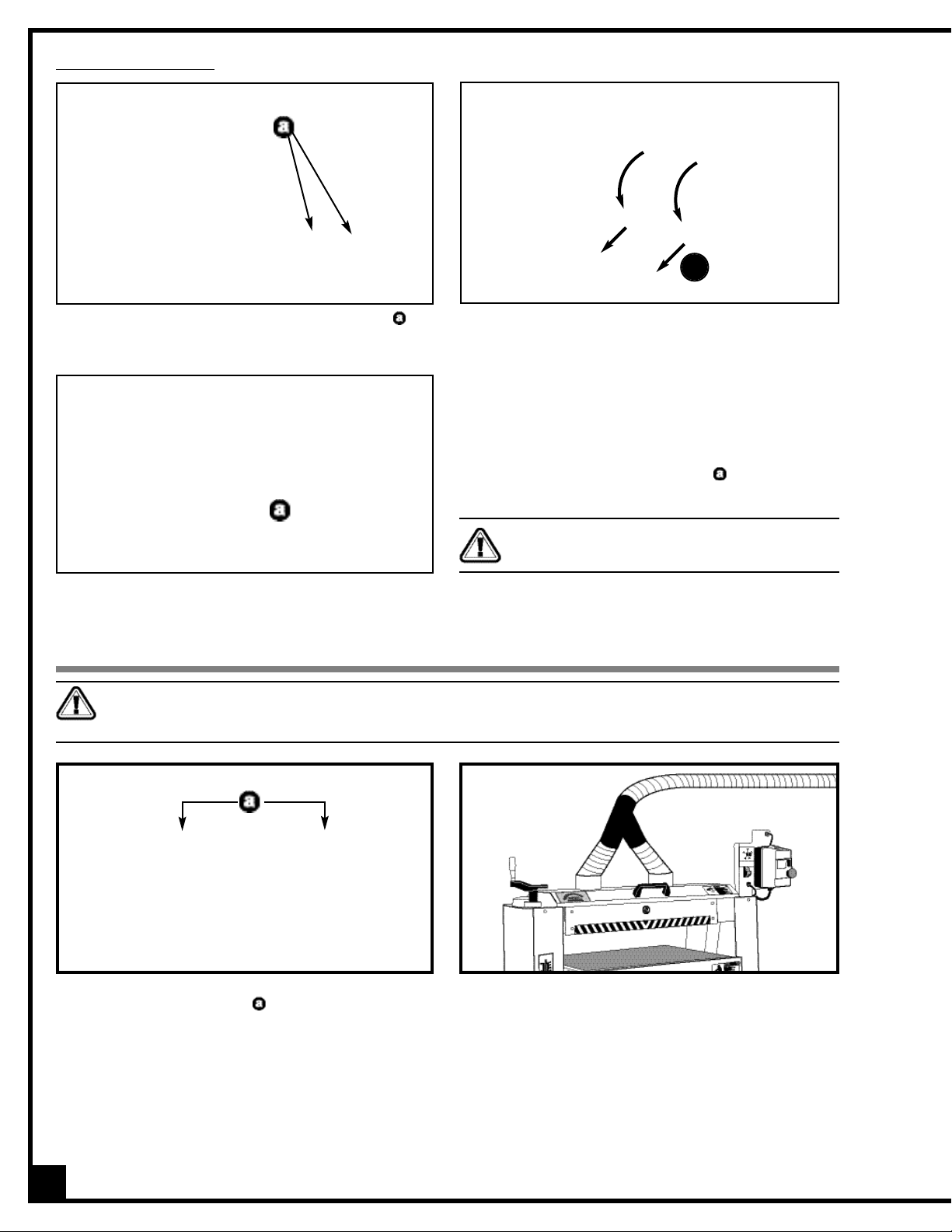
Magnetic safety switch.
Two (2) 4” dust outlets.
Graduated depth scale in both inches and
metric to indicate sanding thickness.
Conveyor belt equipped with a safety
switch with removable key.
Dual v-belt driven sanding drums.
Variable speed conveyor belt.
MAXIMUM SANDING WIDTH
24» (610 mm)
MAXIMUM SANDING THICKNESS
5” (127 mm)
MINIMUM SANDING THICKNESS
1⁄4” (6 mm)
MINIMUM SANDING LENGTH
5” (127 mm)
DRUM DIAMETER
5” (127 mm)
DRUM SPEED
1550 RPM
FEEDING SPEED
3 to 20 FPM (0.93 – 6.2 M/MIN)
VARIABLE
BASE DIMENSIONS (L X W)
42 1/2” x 16 1/2” (1079.5 x 419 mm)
MAIN MOTOR
3 HP, 220 V, 1 Ph, 15 A
CONVEYOR MOTOR
1/6 HP
WEIGHT
570 LBS (259 kg)
REVISION 3 - APRIL 04/14
© COPYRIGHT GENERAL INTERNATIONAL
Page 2

THANK YOU
for choosing this General® International model 15-250 M1 24”
Horizontal Double Drum Sander.This machine has been carefully tested and inspected before
shipment and if properly used and maintained, will provide you with years of reliable service.
To ensure optimum performance and trouble-free operation, and to get the most from your
investment, please take the time to read this manual before assembling, installing and operating the unit.
The manual’s purpose is to familiarize you with the safe operation,basic function,and features
of this horizontal double drum sander as well as the set-up, maintenance and identification of
its parts and components. This manual is not intended as a substitute for formal woodworking
instruction,nor to offer the user instruction in the craft of woodworking.If you are not sure about
the safety of performing a certain operation or procedure, do not proceed until you can confirm, from knowledgeable and qualified sources, that it is safe to do so.
Once you’ve read through these instructions, keep this manual handy for future reference.
All component parts of General® International machinery are carefully tested and inspected during all stages of
production, and each machine is thoroughly inspected upon completion of assembly. Because of our commitment to quality and customer satisfaction,General® International agrees to repair or replace, within a period of 24
months from date of purchase,any genuine part or parts which, upon examination, prove to be defective in workmanship or material. In order to obtain this warranty, all defective parts must be returned freight pre-paid to
General® International Mfg. Co., Ltd. Repair s attempted without our wr itten author ization will void this warranty.
GENERAL ® INTERNATIONAL WARRANTY
Disclaimer:
The information and specifications in this manual pertain to
the unit as it was supplied from the factory at the time of printing.
Because we are committed to making constant improvements,
General® International reserves the right to make changes to components, par ts or features of this unit as deemed necessary, without prior
notice and without obligation to install any such changes on previously
delivered units. Reasonable care is taken at the factory to ensure that
the specifications and information in this manual corresponds with that
of the unit with which it was supplied. However, special orders and “after
factory” modifications may render some or all information in this manual inapplicable to your machine. Further, as several generations of this
24” horizontal double drum sander and several versions of this manual
may be in circulation,if you own an earlier or later version of this unit,this
manual may not depict your machine exactly. If you have any doubts
or questions contact your retailer or our support line with the model and
serial number of your unit for clarification.
GENERAL® INTERNATIONAL
8360 Champ-d’Eau, Montreal (Quebec) Canada H1P 1Y3
Telephone (514) 326-1161 • Fax (514) 326-5555
www.general.ca
Page 3

1. Do not operate the sander when tired,distracted,or
under the effects of drugs, alcohol or any medication that impairs reflexes or alertness.
2. The working area should be well lit, clean and free
of debris.
3. Keep children and visitors at a safe distance when
the sander is in operation; do not permit them to
operate the sander.
4. Childproof and tamper proof your shop and all
machinery with locks, master electrical switches
and switch keys, to prevent unauthorized or unsupervised use.
5. Stay alert! Give your work your undivided attention.
Even a momentary distraction can lead to serious
injury.
6. Fine particulate dust is a carcinogen that can be
hazardous to health. Work in a well-ventilated area
and whenever possible use a dust collector and
wear eye,ear and respiratory protection devices.
7. Do not wear loose clothing, gloves, bracelets,
necklaces or other jewelry while the sander is in
operation.
8. Be sure that adjusting wrenches, tools, drinks and
other clutter are removed from the machine and/or
the feed table surface before operating.
9. Keep hands well away fr om the sanding drums and
all moving parts. Use a brush, not hands, to clear
away sanding dust.
10. Be sure sanding belts are securely installed on the
sanding drums.
11. Do not operate the sander if the sanding betls are
damaged or badly worn.
12. Do not push or force the workpiece into the sander.
The machine will perform better and more safely
when working at the feed rate for which it was
designed.
13. Avoid working from awkward or off balance positions.Do not overreach and k eep both feet on f loor.
14. Keep guards in place and in working order.If a
guard must be removed for maintenance or
cleaning, be sure it is properly re-attached before
using the tool again.
15. Never leave the machine unattended while it is running or with the power on.
16. Use of parts and accessories NOT recommended
by General
® International may result in equipment
malfunction or risk of injury.
17. Never stand on the machine. Serious injur y could
occur if the sander is tipped over or if the sanding
drums are unintentionally contacted.
18. Always disconnect the tool from the power source
before servicing, changing accessories or sanding
belts, or before performing any maintenance or
cleaning, or if the machine will be left unattended.
19. Make sure that switch is in "OFF" position before
plugging in the power cord.
20. Make sure the tool is properly grounded. If equipped with a 3-prong plug it should be used with a
three-pole receptacle. Never remove the third
prong.
21. Do not use this sander for other than its intended use.If used for other purposes,General
® Inter-
national disclaims any real implied warranty and
holds itself harmless for any injury,which may result
from that use.
Rules for Safe Operation
To help ensure safe operation, please take a moment to learn the machine’s applications and limitations, as well as potential hazards. General® International disclaims any real or implied warranty and
hold itself harmless for any injury that may result from the improper use of it’s equipment.
Page 4
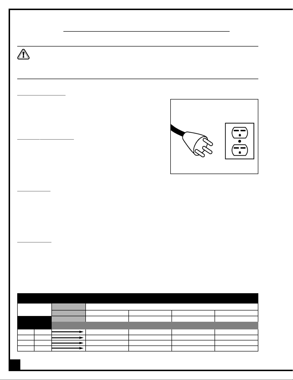
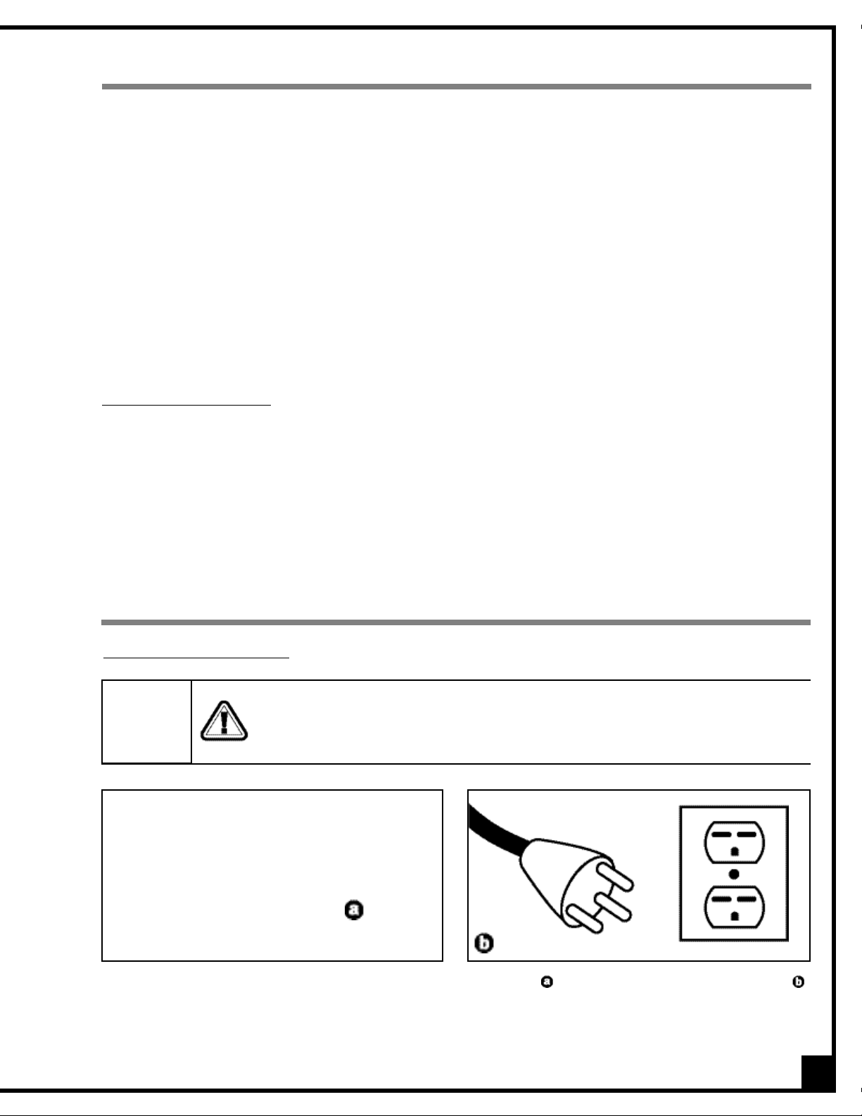
EELLEECCTTRRIICCAALL RREEQQUUIIRREEMMEENNTTSS
4
GROUNDING INSTRUCTIONS
In the event of an electrical malfunction or short circuit, grounding
reduces the risk of electric shock to the operator. The motor of this
machine is wired for 220V single phase operation and is equipped with
a 3-conductor cord and a 3-prong grounded plug to fit a matching
grounded type receptacle. (Fig. 1).
DO NOT MODIFY THE PLUG PROVIDED
If it will not fit your receptacle,have the proper receptacle installed
by a qualified electrician.
Check with a qualified electrician or service person if you do not completely understand these grounding instructions, or if you are not sure
the tool is properly grounded.
CIRCUIT CAP
ACITY
Make sure that the wires in your circuit are capable of handling the amperage draw from your machine,as well as
any other machines that could be operating on the same circuit. If you are unsure, consult a qualified electrician.
If the circuit breaker trips or the fuse blows regularly,your machine may be operating on a circuit that is close to its
amperage draw capacity.However, if an unusual amperage draw does not exis t and a power failure still occurs,
contact a qualified technician or our service department.
EXTENSION CORDS
The use of an extension cord is not generally recommended for 220V. If you find it necessary, use only 3-wire
extension cords that have 3-prong grounding plug and a matching 3-pole receptacle that accepts the tool’s
plug. Repair or replace a damaged extension cord or plug immediately.
If you find it necessary to use an extension cord with your machine make sure the cord rating is suitable for the
amperage listed on the motor I.D. plate. An under sized cord will cause a drop in line voltage resulting in loss of
power and overheating.The accompanying chart shows the correct size extension cord to be used based on cord
length and motor I.D.plate amp rating.If in doubt, use the next heavier gauge.The smaller the number, the heavier
the gauge.
TABLE - MINIMUM GAUGE FOR CORD
VOLTS
110 V
MORE
THAN
18
18
16
14
220 V
AMPERE
RATING
NOT
MORE
THAN
0
6
10
12
6
10
12
16
16
16
16
12
16
14
14
-
14
12
12
-
25 ft.
50 ft.
50 ft.
100 ft.
100 ft.
200 ft.
150 ft.
300 ft.
TOTAL LENGTH OF CORD IN FEET
AWG
Fig. 1
Before connecting the machine to the power source, verify that the voltage of your power supply corresponds with
the voltage specified on the I.D. nameplate located on the back of the machine. A power source with greater voltage than needed can result in serious injury to the user as well as damage to the machine. If in doubt, contact a
qualified electrician before connecting to the power source.
This tool is for indoor use only. Do not expose to rain or use in wet or damp locations.
Page 5
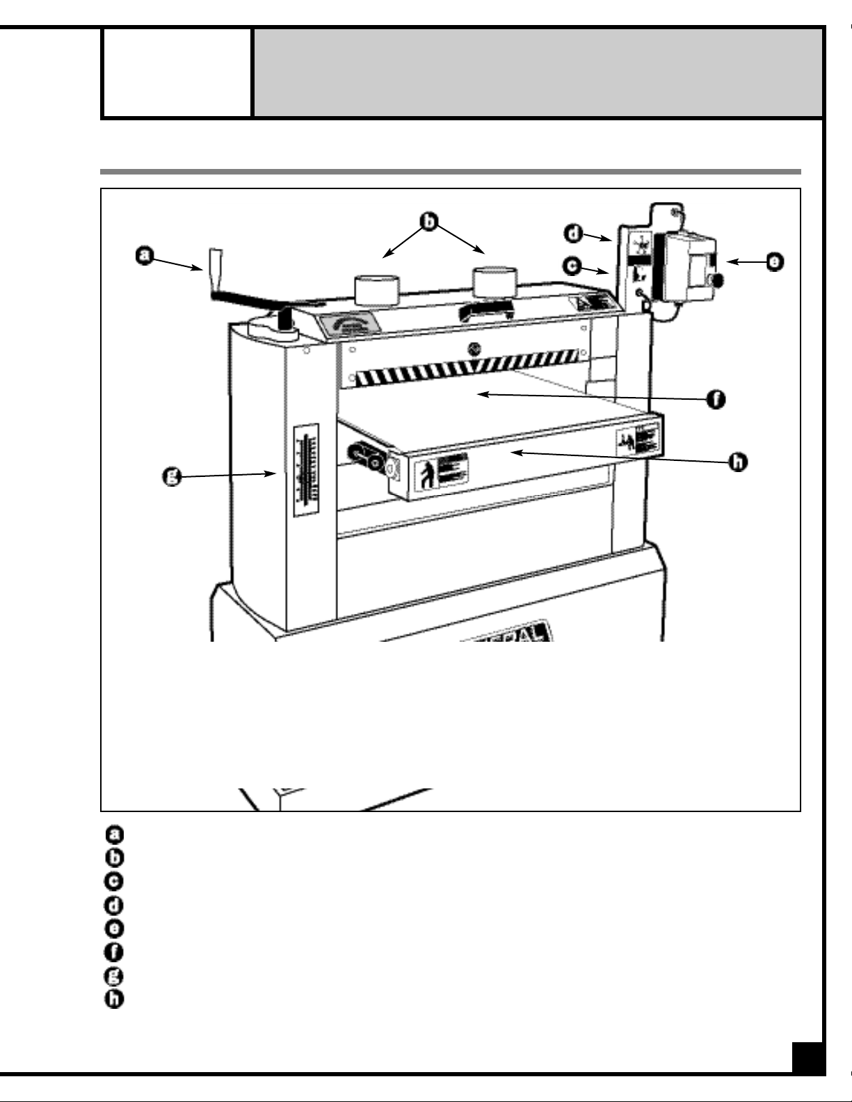
24” HORIZONTAL DOUBLE DRUM SANDER
15-250 M1
IDENTIFICATION OF MAIN PARTS AND COMPONENTS
CRANK HANDLE
DUST OUTLETS
CONVEYOR MOTOR START/STOP SWITCH WITH SAFETY KEY
CONVEYOR BELT SPEED ADJUSTING KNOB
SANDING DRUM MOTOR MAGNETIC POWER SWITCH
CONVEYOR BELT
DEPTH GAUGE
CONVEYOR TABLE
5
Page 6
UNPACKING
Carefully unpack and remove the unit and its components from its shipping container and check for missing or
damaged items as per the list of contents below.
NOTE: Please report any damaged or missing items to your GENERAL® INTERNATIONAL distributor immediately.
LIST OF CONTENTS
Once the parts have been removed from the packaing, you should have the following items:
QTY
24”HORIZONTAL DOUBLE DRUM SANDER . . . . . . . . .1
HARDWARE BAG (from left to right)
— HANDLE KNOB . . . . . . . . . . . . . . . . . . . . . . . . . . . .1
— CRANK HANDLE . . . . . . . . . . . . . . . . . . . . . . . . . . .1
— 5 MM ALLEN KEY . . . . . . . . . . . . . . . . . . . . . . . . . .1
— 6 MM T-HANDLE ALLEN WRENCH . . . . . . . . . . . . .1
— 2 MM T-HANDLE ALLEN WRENCH . . . . . . . . . . . . .1
— 12-14 MM COMBINATION WRENCH . . . . . . . . . .1
ADDITIONAL REQUIREMENTS FOR SET UP
• Extra person for help with lifting
• Phillips Screwdriver
• 10 mm open end wrench
• Utility knife
• Flat piece of wood or any similar non-cutting
object
6
Page 7
7
ESTABLISHING A SAFETY ZONE
For shops with frequent visitors or multiple operators, it is
advisable to establish a Safety Zone around shop machinery. A clearly defined “no-go” zone on the floor around
each machine can help avoid accidents that could cause injury to either the operator or the shop visitor.It is advisable to take a few moments to either paint (using non-slip paint) or using tape, define on the floor the limits or
perimeter of each machines safety zone. Take steps to ensure that all operators and shop visitors are aware that
these areas are off limits whenever a machine is running for everyone but the individual operating the unit.
PLACEMENT WITHIN THE SHOP / ESTABLISHING A SAFETY ZONE
PLACEMENT WITHIN THE SHOP
This machine should be installed and operated only on
a solid, flat and stable floor that is able to support the
weight of the sander (570 lbs/259 kg) and the operator .
Using the dimensions shown in Fig. 2 as a guideline,
plan for placement within your shop that will allow the
operator to work unencumbered and unobstructed by
foot traffic (either passing shop visitors or other shop
workers) or other tools or machinery.
1. Install the conveyor table adjustment crank handle, , on the shaft loca ted on the top left end of
the sander.The slots in the crank handle must be
aligned with the spring pin on the shaft, .
ASSEMBLY INSTRUCTIONS
For your conv enience this sander is shipped fr om the factory partially assembled and requires only minimal assembly and set up before being put into service.
2. Screw the knob,,into the threaded hole in the
crank handle.
INST
ALL THE CONVEYOR TABLE ELEVATION CRANK HANDLE
Fig. 2
This sander is heavy. Do not over-exert. The help of an assistant will be needed for the following step.
To limit the risk of serious injury or damage to the machine, any equipment used to lift this machine (for klift or lift-
ing hook) should have a rated capacity in excess of 570 lbs (259 kg).
Do not plug in or turn on the sander until you have completed the installation and assembly steps described in
this section of the manual.
Page 8
INSTALL THE CONTROL BOX
3. Tighten the bolts to secure the control box in place,
with a 10 mm open end wrench,.
CONNECTING TO A DUST COLLECTOR
The 24" horizontal double drum sander is equipped with
two 4”diameter dus t outlets , , on top of the machine,
allowing for the connection to a dust collector
(not
included)
.
If you do not already own a dust collection system consider contacting your General® International distributor for
information on our complete line of dust collection systems and accessories or visit our Web Site at: www.general.ca.
Be sure to use appropriate sized hose and fittings
(not
included)
and check that all connections are sealed
tightly to help minimize airborne dust.
8
Note: Recommended dust collection CFM requirements for this sander is 1200 CFM (or 2HP dust collector).
1. Loosen, but do not remove, the 2 hex bolts,, in-
stalled on the top right hand corner of the machine
.
2. Slide the control box onto the heads of the bolts.
1
2
Do not plug in the power cord yet.
Do not operate this sander without an adequate dust collection system properly installed and running. Operating
this sander without adequate dust collection can lead to equipment malfunction or dangerous situations for the
operator or other individuals in the workshop.
Page 9
BASIC ADJUSTMENTS AND CONTROLS
CONNECTING TO A POWER SOURCE
Once the assembly steps have been completed, uncoil the power cord, , and plug it into an appropriate outlet, ,
(refer back to the section entitled "Electrical Requirements" and make sure all requirements and grounding instructions are followed).
This 24”horizontal double drum sander is designed for surface sanding of wooden cabinet doors, flat wooden panels, wide glue-ups and other natural wood products only. This sander is not intended (and should not be used) to
sand any material other than wood.
The main time saving feature of this unit is that it allows for sanding at 2 successive grits in one single pass. Use a
rougher (lower numbered) grit sandpaper on the front drum and a finer (higher numbered) grit sandpaper on the
rear drum.
Selecting the right combination of grits to use on each drum will depend on exper ience, personal preference and
the finish requirements of the work. Keep in mind that normal sanding principals apply and that each successive
grit further smoothens the surface and removes the scratch marks left by the previous grit. For ideal results never
install a grit on the rear drum that is too high a jump up (no more than 2 gr its higher) from the grit installed on the
front drum. As an example, if a 100 grit pa per is installed on the front drum, then either a 120 or 150 would be suitable for the rear drum.
BASIC FUNCTIONS OF THE UNIT
BASIC PRINCIPLES OF SANDING
It is always preferable to remove less material per pass and take multiple passes.This can extend sanding belt life,
place less strain on the motor and provide better workpiece finish quality.
Note: As with any other drum or belt sander ,depending on the final finish quality you require, some final hand sanding may
be required.
9
SWITCHES
OFF
To avoid risk of shock or fire do not operate the unit with a damaged power cord or plug.
Replace damaged cord or plug immediately.
To avoid unexpected or unintentional start-up, make sure that both of the power switches on
the sander are in the OFF position before connecting to a power source.
Page 10
10
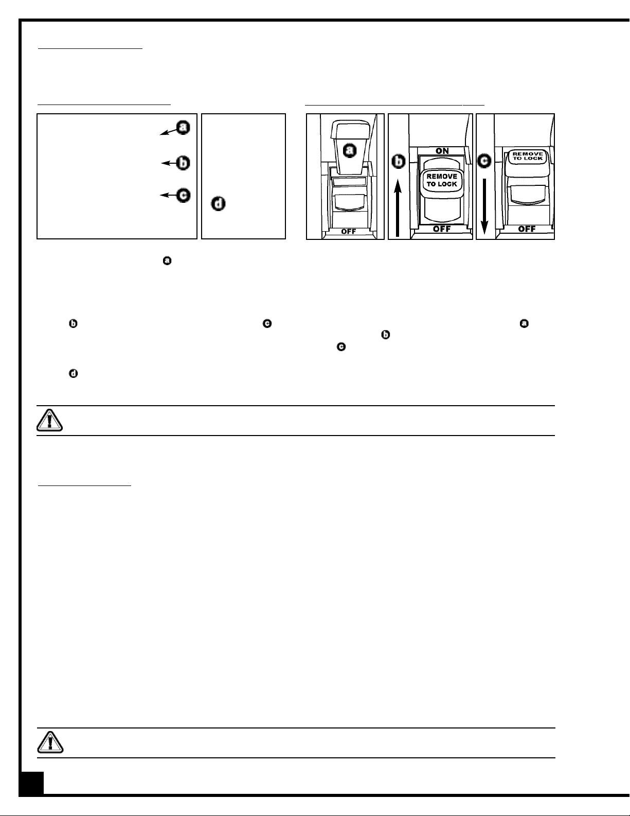
DRUM MOTOR MAGNETIC SWITCH
This model 15-250 M1 drum sander is equiped with a
MAGNETIC SAFETY SWITCH , . located on the control
box, designed to protect the unit and the user from
power surges, power outages and unwanted or unintentional start-up.
The switch assembly is equipped with a GREEN “START”
button, , and a RED spring loaded “STOP”button, .
Once the RED “STOP” button has been pressed, the
machine can only be started by turning the BLACK
inner part of the button to the right to release the stop
button, .
CONVEYOR MOTOR SWITCH WITH SAFETY KEY
SAFETY KEY*
ON
*
PREVENTS START-UP WHEN REMOVED
OFF
This model 15-250 M1 is also equiped with a simple
ON/OFF switch for the conveyor motor, featuring a
removable lock out safety key.
To start the conveyor belt, inser t the safety key, , and
lift the switch up, .To stop the machine,pull the switch
down, .
To prevent unauthorized use or unintentional start-up,
remove the safety key and store it in a safe place
whenever the sander is not in use.
ON/OFF POWER SWITCHES
This sander is equipped with 2 different ON/OFF power switches: one magnetic switch for the drums motor and one
switch with a safety key for the conveyor motor.
OVERLOAD PROTECTION
The magnetic safety switch on this sander is equipped with an overload protection feature.To prevent an electrical
overload from damaging the motor, in the event of a spike in line voltage or amperage draw,the internal overload
protector will automatically be tripped, thereby cutting off power to the motor.
Note: The most common causes of such overloads are:
1. Overworking the motor by attempting to remove too much material in a single pass, thereby causing an increase in power consumption and a spike in amperage draw.
2. An electrical extension cord that is too long or not the correct gauge of wire,which can also cause an increase
in amperage draw. If an electric extension cord must be used, follow the instructions and refer to the chart in
the electrical requirements section at the beginning of this manual.
3. Overworked circuit caused by operating on a circuit that is close to its amperage draw capacity.Make sure the
circuit being used is capable of handling the amperage draw from this machine as well as any other electrical
devices operating on the same circuit. If you are unsure, consult a qualified electrician.
To reset the overload protection switch after it has been tripped proceed as follows:
Remove the switch key and store it in a safe place, out of the reach of children, whenever the sander is not in use.
To avoid unexpected or unintentional start-up be certain that both of the power switches have been set to the off
position before re-setting the overload protection switch.
Page 11

11
1. Set both of the power switches on the sander to the
off position
,,
and disconnect the machine from
the power source
,.
Note: If the sander is permanently connected to a circuit (hard-wired), set the wall panel circuit breaker or
main circuit interrupter to the off position.
2. Unscrew the 2 screws
,,
and remove the control
box front cover
.
SWITCHES OFF
4. Reinstall and rescrew the control box cover.
5. Reconnect the sander to the power source.
6. You can now restart the drum motor by pushing on
the green button ON.
3. Press the blue reset button
,.
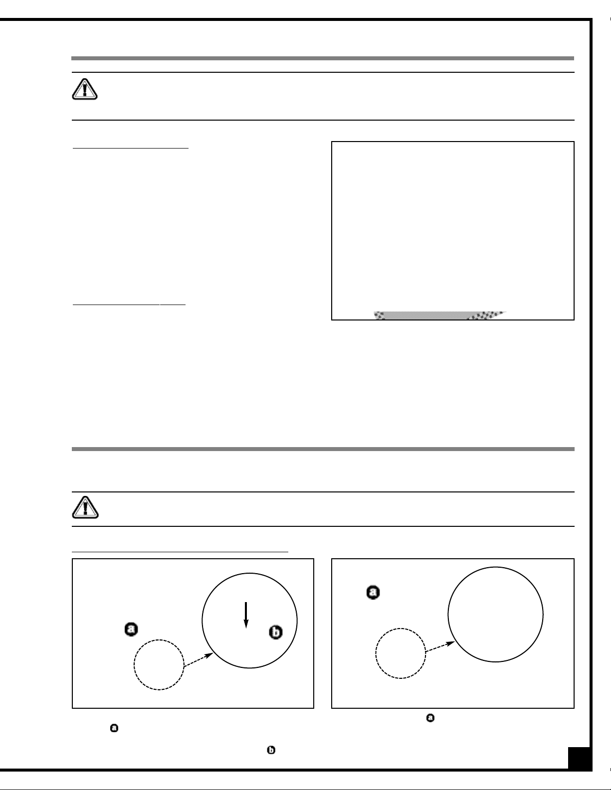
RAISING/LOWERING THE CONVEYOR TABLE
The conveyor ta ble can be raised or lowered ,, as needed to suit the thickness of the workpiece, by rotating the
crank handle,. (Fig. 3)
Note: The maximum workpiece thickness capacity for this machine is 5”
.
1. Put the workpiece on the conveyor belt.
2. Set the height of the convey or table so that the w ork-
piece barely touches the front drum
,.
Note: To avoid overworking the motor, creating a potential
circuit overload, or damaging the sanding drums, do not
force the workpiece against or into the drums.
DOWN
UP
RAISING/LOWERING THE CONVEYOR TABLE
Note: The depth gauge,,on the front of the machine can be
used as a reference but it is not intended for high precision
measurements.
Fig. 3
WORK PIECE
DRUM
DO NOT
CONVEYOR BELT
DO
* Effect exaggerated for clarity
Never attempt to sand workpieces that are greater
than 5”.
Page 12

12
CHANGING FEED SPEED
The conveyor speed ranges from 3 to 20 FPM (Feet Per
minute).
The feed speed adjustment knob
,,
is located on the
control box,on the right hand side of the machine
.
- Turn the knob clockwise, , to increase the feed
rate.
- Turn the knob counter-clockwise, , to decrease
the feed rate.
As a general guideline, more aggressive sanding using lower grits or sanding wider boards should be done at slower speeds and sanding using higher grits or sanding narrow boards can be done at higher speeds.
Given that sanding in successive grits is done in a single pass,results can vary widely depending on a variety of factors. Experiment with feed speeds based on the workpiece material, board width, depth of sanding,grit selection as
well as required finish results.
Decrease
speed
Increase
speed
For optimal results, the rear drum
,,
should be set fra-
ctionally lower than the front drum
,,
by the depth of
the grit of the paper on the front drum,.
-
The front drum his factory set parallel with the conveyor table and needs no further adjustments.
-
The rear drum is micro-ajustable. It can be slightly
raised or lowered at each end and must be kept
parallel to the table.
ADJUSTING THE HEIGHT OF THE REAR DRUM
To set the rear drum to the correct height proceed as follows:
1. Place two gauge blocks (not included) on the
conveyor belt, positioned one under each end of
the front drum (with the sanding belt installed on).
(Fig. 4)
Note: To achieve parallelism with the front drum, any
gauge blocks that are used (whether purchased or
shop made) must be a matching set and must both
be at the same height.
2. Raise the table until the gauge blocks barely
touch the drum.
Fig. 4
* Effect exaggerated for clarity
Page 13

Always make sure the sander is disconnected from the power source before opening the drum cover and removing/installing sanding belts or adjusting the height of the rear drum.
3. To access the sanding belts, unlock the drum co-
ver latch, , and open the top cover.The sanding
belts are tightly wound around the drums and attached at both ends by spring loaded clamps,.
(Fig. 5)
4. Remove the sanding belt from the rear drum. (See
section “Removing the sanding belts” on page 17).
5. Place the two gauge blocks, one under each end
of the rear drum.
6. Using the 6 MM T-Handle Allen wrench provided,
slowly turn the micro-adjustment screws located
at each end of the drums, , counterclockwise to
lower the drum,, until it barely touches the
gauge blocks. (Fig. 6)
7. Remove the gauge blocks and reinstall the sand-
ing belt on the rear drum. (See section “Mounting
a new sanding belt” on page 18). The rear drum is
now set lower than the front drum by the thickness
of the sandpaper on the front drum.
8. Given that the rear drum must be lower than the
front drum only by the depth of the grit on the paper, , (and not by the thickness of the paper including the grit, ), turn the micro-adjustment
screws clockwise, approx. 1/8 of a turn as per the
indicator dials, . This will raise the drum by the
fraction corresponding to the depth of the paper
without the grit, . (Fig. 7)
Fig. 5
Fig. 6
DRUM
PAPER
GRAIN
1/8
Note: You will not get an optimal result if the rear
drum is not low enough. On the other hand, attempting to remove too much material in one single pass
may result in workpiece burn problems or in motor
overheating.
Do not use this sander as a thickness planer. Never attempt to remove more than the depth of the grit of the sanding belts in any single pass. Too much friction will cause belts to overheat and wear prematurely, and, in extreme
cases, may cause burns in the workpiece.
Fig. 7
13
Page 14

OPERATING INSTRUCTIONS
CHECKLIST BEFORE STARTING
• Make sure a dust collector is properly attached.
• If multiple boards are to be sanded, collect all workpieces together and set them nearby on a table or bench
within easy reach.
• Make sure that the sanding belts are properly installed, that is , wound around the drums, taut and without
spaces between the belts edges. Otherwise, the sanding belts may rip when in contact with the workpiece.
• If working with longer workpieces, make sure to have adequate out feed support safely set-up and ready
before sanding.
DO
DO NOT
Tip: To avoid sanding snipe – which is a small depression in the surface of a workpiece across its width caused by a
variation in the sanding depth during a given pass - it is important to keep the workpiece level on the feed table until
it has completely cleared contact with the sanding drums. It is advisable to use an outfeed table or some form of outfeed support when sanding workpieces of 4’ or more in length.Allowing the leading edge of a longer workpiece to hang
or sag off of the outfeed end of the conveyor table should be avoided as it will lift the trailing end of the workpiece up
into the sanding drums and cause uneven sanding depth and snipe.
WITHOUT AN ADEQUATE OUTFEED SUPPORT
14
WITH AN ADEQUATE OUTFEED SUPPORT
Make sure to have on safety glasses as well as hearing and respiratory protection at all times when using the
sander.
Make sure you and any assistants are wearing safe appropriate workshop attire. Roll up long sleeves, secure long
hair and remove any je welry: watches, rings, bracelets or anything that could become caught in the conveyor feed
rollers or the drums, potentially causing serious injury.
Page 15

15
OPERATIONS STEP-BY-STEP
1. Set the height of the rear drum (see section: “Adjusting the height of the rear drum” on page 12.)
2. Place the workpiece on the conveyor belt.
3. Set the height of the conveyor table. (see section: “Raising/Lowering the Conveyor Table” on page 11.)
4. Remove the workpiece from the conveyor belt.
5. Tur n on your dust collector.
6. Press the green "ON" button on the control box to start the sanding drum motor.
7. Insert the safety key into the conveyor belt switch.
8. Set the feed speed to minimum before starting the conveyor belt, then lift the switch up to star t the conveyor
motor. Gradually increase the speed , until you reach the desired feeding speed.
9. Place the workpiece on the center of the conveyor belt and pass the board once.
10. Step to the rear of the machine and pick up the workpiece on the out feed.
Note: Consider using a proper support on the out feed for workpieces longer than 4'.
11. Pass the workpiece once again.
12. Inspect and slowly run your hand over your workpiece to determine whether or not further passes are required.
Tip: For better workpiece finish quality, make shallower passes with the conveyor table height adjusted so you
just start hearing the contact noise.
13. If needed, pass the workpiece again, raising the table not more than 1/8 of a turn a t a time. Repeat until
desired finish quality is achieved.
Note: To avoid overworking the motor, creating a potential circuit overload, or damaging the sanding drums , do not
force the workpiece against or into the drums.
TO STOP THE MACHINE
1. Press the red "OFF" button, on the control box to stop the rotation of the drums.
2. Push the red switch to the "OFF”position to stop the conveyor belt.
3. Remove the key switch. This will prevent unauthorized use of the machine.
4. Turn your dust collector off.
Always turn off the sander BEFORE turning off the dust collector.
Do not use this sander as a thickness planer. Never attempt to remove more than the depth of the grit of the sanding belts in any single pass. Too much friction will cause belts to overheat and wear prematurely, and, in extreme
cases, may cause bur ns in the workpiece.
Always turn on the dust collector BEFORE starting the sander.
Keep hands away from the rotating drums and conveyor belt. Do not force the workpiece towards the sanding
drums, let the conveyor belt feed the workpieces.
To reduce the risk of damage to the sander or the workpiece, as well as a potential for personal injury, after initial
set-up as well as before each use, make sure that everything is securely installed and that all fasteners and moving parts on this sander are locked in place before starting the machine.
Page 16

16
Keep threaded rods, , and gears, , located at either end of the machine greased and free of dust or debr is.
Clean and remove dust,debris, and old grease after every 10-15 hours of use. After cleaning, re-a pply a generous
coating of any common automotive bearing grease. (Fig. 8)
LUBRICATION
PERIODIC MAINTENANCE
1. Inspect/test the ON/OFF switches before each use.Do not operate the sander with a damaged switch; replace
a damaged switch immediately.
2. Keep the machine, especially motor and conveyor, as well as the feed table conveyor clean and free of dust
or glue. Vacuum or brush off any loose debris and wipe down the machine and the conveyor occasionally
with a damp rag.
3. The drums must always be kept clean. Dir t on the dr ums will cause belt slippage.
4. The motor and drum bearings are sealed and permanently lubr icated – no further lubrication is required.
5. Periodically inspect the power cord and plug for damage,as well as the sanding belts, the drums, the motor
pulleys, drive belts and the conveyor belt.
REQUIRED MAINTENANCE
MOUNTING AND REPL
ACING THE SANDING BELTS
Sanding belts should be replaced when worn out.
Pre-cut replacement belts can be purchased in a variety of grits from your General® International dealer under the
following parts numbers:
• 36 grit - 15-251 • 120 grit - 15-255
• 60 grit - 15-252 • 150 grit - 15-256
• 80 grit - 15-253 • 180 grit - 15-257
• 100 grit - 15-254 • 220 grit - 15-258
Note:
Unscrew and remove both left and right cover to access
the conveyor elevation mechanism.
Fig. 8
Never operate the sander with any damaged part. Replace a damaged part at the first visible signs of damage.
Disconnect machine from power source, before performing any maintenance or lubrication.
Page 17

You can also purchase them from your local tool, abrasives or sharpening supply dealer. You can find these products in most areas. However, we recommend that you choose higher quality brand name belts. If the sanding
paper is too thick or too thin, or of inconsistent quality, it may not be properly gripped by the two-step clamps.
Tip: Cleaning the sand paper with a belt dresser will extend the life of the sand paper. Consult your local distributor.
For users who prefer to purchase abrasives in longer uncut rolls or from bulk suppliers, the following cutting diagram
can be used to assist in cutting the bulk paper to the correct size for this sander.
*MEASURED & CUT WITH ABRASIVE GRIT FACE SIDE DOWN.
14 3/8”
111 5/8”
REMOVING THE SANDING BELTS
Make sure the sander is disconnected from the
power source before removing/installing the
sanding belts.
1.
To access the sanding belts, unlock the drum cover
latch,
are tightly wound around the drums and attached at
both ends by spring loaded clamps,
Fig. 9
, and open the top cover. The sanding belts
. (Fig. 8).
Fig. 8
Fig. 10
2. Push the spring loaded clamps forward, , and remove the tab of the sanding belt from the slot at the right end
of the drum,
3. Unwind the sanding belt then push the left two-step clamp forward and remove the tab of the sanding
belt from the slot of the left end of the drum.
. (Fig. 9 and 10)
17
Page 18

18
1. Pull and hold the left spring loaded clamp.
2. Insert the left tab of the sanding belt in the slot,
pushing all the way in (as far as possible), then
release the clamp to lock the tab in place.
MOUNTING A NEW SANDING BELT
3. Tightly wind the sanding belt around the drum, making sure that there are no spaces between the edges,,
of the sanding belt, that the belt is taut and that there are no bumps,. Do not overlap the edges,.
Note: To extend belt life and avoid premature breakage, take note of the direction of the arrows printed on the
inside of the sanding belt to make sure you install the belt in the correct direction.
DO NOTDO
Page 19

19
4. Push and hold the right two-step clamp for-
ward with your thumb.
6. Release
only
the first stage of the clamp, sliding
your thumb down towards the bottom to lock the
tab in place.
7. Release the clamp, . This will bring proper ten-
sion, , to the sanding belt.
5. Insert the right tab of the sanding belt in the slot,
pushing all the way in (as far as possible),until it is
tight,.
Note: The spring loaded clamp at the right end of the drums is a two stage spring. The first stage grabs the paper
and the second stage pulls the clamp backward inside the drum, providing proper tension to the sanding belt.
Tip: Use a flat stick or any similar non-cutting object to force the tab further into the slot so it is as tight as possible,
.
Note: On occasion, due to slight variations in the length of the sanding belts or in the depth of installation in the
left belt clamp, even with the belt properly wound onto the drum, there may be slightly too much belt left at the
right end of the drum. This may cause a slight overlap on the last wrap on the drum, , and this despite installing
the right end of the belt as far into the clamp as it will go. In such cases, to avoid having to unroll and realign
the entire belt on the drum after it has already been secured at both ends and is otherwise properly installed,
use a utility knife or scissors to cut and remove the overlapped section of paper. To avoid belt tearing during
sanding, avoid cutting at
right angles, , - make a rounded or curved cut, .
FIRST STAGE SECOND STAGE
Page 20

20
Note: With the sanding belt tab,,properly inserted in the clamp, the clamp assembly, ,should not pull back more than
3/4", , from the slot in the dr um, . If the clamp assembly pulls back further than 3/4" the sanding belt tab needs to be
inserted further into the clamp to remove some of the slack in the belt. Otherwise the paper will not be properly tensioned
on the drum and the belt may loosen, unwind, or possibly tear when it comes in contact with the workpiece.
8. Once the sanding belts have been properly installed and tensioned on the drums, close and lock the drum
cover.
1. Unscrew and remove both left and right covers ,
the front and rear panels, ,then the front and rear
shield plates, .
2. With a 14 mm open end wrench, loosen but do
not remove the nut and lock nut, , located on
the motor positioning plate, .
DRUM MOTOR BELT REPLACEMENT
The sanding drums are driven by two belts mounted on two pulleys powered by the motor. If the belts become too
loose due to wear or if a breakage occurs, you must replace one or both as needed. Proceed as follows:
3. Lift the motor positioning plate, . This will loosen
the belts, .
4. Carefully remove the belts from the grooves on the
lower pulleys.
Max.
3/4”
3/4”
REAR
REAR
Proceed with caution. Removing the belts from the pulleys will cause the motor to swing freely under it’s own
weight on the support shaft. Do not let it drop. Hold it until it is back down.
Page 21

5. Remove the belts from the upper pulleys, , and
install new belts. (Fig. 11)
6. Lift the motor and install the other end of the
belts in the slot on the lower pulleys.
7. Put the motor back to its initial position, then retighten the lock and lock nut located on the motor positioning plate.
REPLACING MOTOR
Should the motor require replacement, remove the 4
nuts, washers and bolts on the bottom of the motor
base and remove the entire motor assembly.
(Fig. 12)
21
The 3 pressure rollers, , (front, middle and rear) maintain the workpiece on the conveyor belt, preventing it
from lifting up from the conv e y or into the drums.(Fig. 13)
They are factory set to provide a proper amount of
downward pressure to the workpiece. However,with use
and normal wear over time, it may eventually become
necessary to make minor adjustments to the pressure
rollers.
If you notice snipe (which is a small depression in the
surface of a workpiece across its width, caused by a
variation in the sanding depth during a given pass) either at one or both ends of your workpiece,the pressure on
the rollers must be reduced, either by adjusting their height or tension.
Refer to the following symptoms to determine which pressure rollers need to be adjusted:
-
If snipe occurs at the beginning of the board, reduce the amount of pressure on the front and/or middle pressure roller(s).
-
If snipe occurs at the tail end of the board, reduce the amount of pressure on the middle and/or rear pressure roller(s).
Increasing the amount of pressure is achieved by adjusting either the height or the tension of the pressure rollers.
In both cases, some experimentation may be necessary to achieve an ideal adjustment.
ADJUSTING THE PRESSURE ROLLERS
Fig. 11
Fig. 12
Fig. 13
BEHIND
Never attempt to repair motor yourself. Contact a
qualified technician.
Page 22

Note: Generally ,snipe problems occur when pressure rollers are set too low. Less frequently,this problem occurs as a result
of too much tension in the pressure rollers. It is thus possible tha t, although you adjusted the height of the rollers, you still
get snipe on your board. If this is the case, adjust the tension of the roller s. Proceed as follows:
1. To access the set screw and micro-adjustment
spring, unlock the drum cover latch, , and open
the top cover, .
2. Using the 2 mm T-handle Allen key provided, slightly turn the set screws, ,at each end of the
corresponding pressure roller(s) to be adjusted.
3. Close the top cover, plug in the machine and run a test piece though to check for snipe.
4. If needed, continue adjusting the height of the pressure rollers until you get no more snipe on your board.
22
1. To access the micro-adjustment spring,unlock the
drum cover latch,and open the top cover.
2. Slightly turn the phillips head screws, , located at
each end of the corresponding pressure roller(s)
to be adjusted. (Fig. 14)
3. Close the top cover, plug in the machine and r un
a test piece though to check for snipe.
4. Continue adjusting the tension of the pressure
rollers until you get no more snipe on your board.
Fig. 14
If after several adjustments you do not obtain satisfactory results by adjusting the height of the pressure roller,
adjust its tension as follows:
Always turn off and unplug the sander before performing any maintenance or adjustments.
Always turn off and unplug the sander before performing any maintenance or adjustments.
Page 23

RECOMMENDED OPTIONAL ACCESSORIES FOR YOUR SANDER
We offer a large var iety of products to help you increase productivity, accuracy and safety when
using your sander. Here’s a small sampling of accessories available from your local General
International dealer.For a complete list, visit our website at www.general.ca.
Sanding belts
15-251 - 36 Grit
15-252 - 60 Grit
15-253 - 80 Grit
15-254 - 100 Grit
15-255 - 120 Grit
15-256 - 150 Grit
15-257 - 180 Grit
15-258 - 220 Grit
Dust Collector
We have a wide selection
of dust collectors to suit all
your shop needs. Dust collectors contribute to a
cleaner and more healthful workshop environment.
Mobile base
50-025
Easily roll your sander anywhere in your shop.Load
capacity: 500 lbs. Wheels
lock when equipment is in
use.
Fle
xible, e
xpandable 2-
w
ay roller stand. Model
50-167S
Ideal for use for infeed or
outfeed support. 20” wide,
height from 24 1/4” to 37”,
and length from 21” to 51”.
Four 4” high quality swivel
casters with locking foot
levers. 300 lbs load capacity.
Gauge Blocks
30-040
Matching set of two precision aluminum gauge
blocks. Ideal for use in
achieving parallelism
adustments for drum
sanders and planers.
23
NOTES
Page 24

95
47
43
1
168
20
23
25
24
68
42
28
27
24
23
15
15
68
23
32
47
27
11
28
11
22
18
26
27
28
165
28
13
13
170
13
170
14
14
14
6
132
28
42
27
16
47
28
12
8
10
6
9
132
8
10
9
7
7
47
43
42
33
144
43
47
42
131
42
40
143
47
43
47
43
42
166
21
167
42
34
47
43
134
42
47
43
134
35
14
5
27
169
36
132
28
39
37
38
85
131a
132
38
35
41
41
134
134
47
43
42
43
42
27
26
85
132
131
1
2
132
133
2
4
3
5
28
4
28
15
133
27
27
28
11
16
13
170
14
3
15
13
12
14
170
17
28
13
28
68
12
19
170
28
21
167
45
68
135
135
22
27
23
24
23
24
23
168
165
25
30
29
31
169
30
29
31
142
141
24
Page 25

192
136
43
101
124
124
27
93
124
28
130
123
103
107
102
65
65
47
44
109
60
103
107
123
105
106
47
108
47
43
100
104
147
103
110
111
107
109
123
122
123
43
124
47
110
130
107
103
102
123
111
28
101
124
112
118B
192
25
Page 26

92
27
93
27
93
55
48
43
48
81
27
93
51
54
81
26
56
84
85
55
49
53
43
95
145
94
44
95
43
66
55
55
145
69
55
55
27
27
93
44
93
72
70
73
52
145
51
54
145
43
42
75
116
42
74
120
115
121
95
10
119B
77
78
114
113
117
76
76
76
70
66
55
69
55
55
10
79
27
93
93
27
26
62
50
49
43
42
98
99
193
81
56
63
43
42
43
97
42
55
61
161
59
26
27
61
55
50
62
43
42
27
26
81
61
54
61
58a
56
59
58
57
55
55
26
27
93
93
27
64
22
87
22
88
22
81
80
27
94
27
93
93
89
56
93
95
93
27
27
95
27
93
27
26
27
93
87
22
81
86
26
53
22
28
83
90
93
27
26
71
52
27
61
56
82
26
22
88
81
28
27
63
26
26
55
59
61
54
61
59
55
61
58a
58
43
81
81
26
81
57
42
55
43
43
44
27
43
44
26
81
42
96
91
43
140
139
138
137
47
47
47
47
47
47
47
8
13
12
11
10
9
5
4
3
7
6
5
4
3
2
1
0
2
0
1
26
Page 27

162
164
129
128
163
26
27
81
28
27
28
26
27
128
27
26
129
26
81
27
81
129
128
28
27
28
27
26
129
128
27
26
81
26
27
81
27
26
81
162
27
Page 28

28
PAR TS LIST - 15-250 M1
PART N0. REF N0. DESCRIPTION SPECIFICATION QTY
15250-01 20900001 DRUM 2
15250-02 20703010 TWO-STEP CLAMP 2
15250-03 20703010B TWO-STEP CLAMP PLATE 2
15250-04 20703010A SPRING 2
15250-05 20703014A SPRING 2
15250-06 20703014 FIXED CLAMP BRACKET 2
15250-07 20703014B FIXED CLAMP PLATE 2
15250-08 20703014C SPRING 2
15250-09 S0040300 PHILLIPS HEAD SCREW 2
15250-10 S0110300 NUT 3/16"-24UNC 7
15250-11 20900086 RIGHT CLAMP 3
15250-12 20900087 LEFT CLAMP 3
15250-13 20900069 MICRO-ADJUSTMENT SPRING 6
15250-14 S0030580M PHILLIPS HEAD SCREW 6
15250-15 S0120500M NYLON NUT M5X0.8 6
15250-16 20900002 CLAMP BLOCK 2
15250-17 20900003 RIGHT BEARING HOUSING 1
15250-18 20900004 LEFT BEARING HOUSING 1
15250-19 20900005 RIGHT MICRO-ADJUST.BEARING CAP 1
15250-20 20900006 LEFT MICRO-ADJUST.BEARING CAP 1
15250-21 S0020530A MICRO-ADJUSTMENT SCREW 2
15250-22 S05ETW06 CIRCLIP E6 8
15250-23 20703002 BEARING CAP 6
15250-24 C1206205 BEARING 6205 4
15250-25 S0060510 CAP SCREW 8
15250-26 S0210500C FLAT WASHER 38
15250-27 S0230506 LOCK WASHER 5/16" 62
15250-28 S0120500 NUT 5/16"-18UNC 30
15250-29 20900008 DRIVE ROLLER 2
15250-30 S0210532 FLAT WASHER 3/8"X23 2
15250-31 S0020512L LEFT THREADED SCREW 5/16"-18UNCX1"L 2
15250-32 20900009 CORNER BRACKET 4
15250-33 20900010 FRONT UPPER PANEL 1
15250-34 20900011 DUST HOOD SUPPORT PANEL 1
15250-35 20702019 HINGE 2
15250-36 20900012 DUST HOOD/DRUMS COVER 1
15250-37 20703016 DUST HOOD/DRUMS COVER HANDLE 1
15250-38 S0010502 CAP SCREW 5/16"-18UNCX3/4"L 18
15250-39 20900070 UPPER CLASP 1
15250-40 20900071 LOWER CLASP 1
15250-41 20900068 HINGE PAD SS41 2
15250-42 S0030405 PHILLIPS HEAD SCREW 1/4"-20UNC 24
15250-43 S0210401 FLAT WASHER 1/4"X13X1 41
15250-44 S0110400 NUT 12
15250-45 20900013 PULLEY GUARD 1
15250-47 S0230400 LOCK WASHER 1/4" 46
15250-48 20900014 UPPER BRACKET 2
15250-49 20900015 COLUMN SUPPORT BRACKET 2
15250-50 20900016 LOWER BRACKET 2
15250-51 20900017 WORM GEAR 2
15250-52 20900018 WORM 2
Page 29

29
PAR TS LIST - 15-250 M1
PART N0. REF N0. DESCRIPTION SPECIFICATION QTY
15250-53 20900019 BUSHING 2
15250-54 S0520080 CIRCLIP S80 4
15250-55 S0050500 SET SCREW 16
15250-56 S0050406 SET SCREW 5
15250-57 20900020 SCREW HOLDER 2
15250-58A C5151102 BEARING 51102 2
15250-58 20900021 BRONZE COLLAR 2
15250-59 20900022 BEVEL GEAR 4
15250-60 S0010616M HEX HEAD BOLT M6 X 1.0 X 16 4
15250-61 S0010303 HEX HEAD BOLT 3/16"-24UNCX3/8" L 8
15250-62 20900023 GEAR SHAFT BUSHING 2
15250-63 20900024 POSITIONING COLLAR 2
15250-64 20900025 TRANSMISSION SHAFT 1
15250-65 20900067 MOUNTING BRACKET 4
15250-66 20900026 POST COVER 2
15250-68 S0040307 PHILLIPS HEAD SCREW 5/16"-18UNCX1"L 8
15250-69 20900028 BRONZE COLLAR COVER 2
15250-70 S0520015 CIRCLIP S15 2
15250-71 S0310420 PIN 4X20 1
15250-72 20900029 CRANK HANDLE 1
15250-73 10105056A HANDLE KNOB 1
15250-74 20900030 SWITCH MOUNTING PLATE 1
15250-75 W2092301D MAGNETIC SWITCH 1
15250-76 S0030318 SCREW 3/16"-24UNCX3/4"L 4
15250-77 S0040308 FLAT HEAD SCREW 3
15250-78 10401008 CORD BUSHING 1
15250-79 20900066 SWITCH REAR GUARD 1
15250-80 20900031 MOTOR BASE 1
15250-81 S0020501 HEX HEAD BOLT 28
15250-82 20900032 MOTOR ADJUSTMENT PLATE 1
15250-83 M0000000 MOTOR 1
15250-84 20900033 DRIVE PULLEY 1
15250-85 S0430640 KEY 6X40 3
15250-86 20900034 BASE SHAFT 1
15250-87 20900035 POSITIONING SHAFT 2
15250-88 20900036 SCREW 2
15250-89 20900037 FRONT COVER 1
15250-90 20900038 REAR COVER 1
15250-91 20900039 FRONT PANEL 1
15250-92 20900040 REAR PANEL 1
15250-93 S0010500 CAP SCREW 5/16"-18UNCX1/2" 20
15250-94 20900041 SHIELD PLATE 2
15250-95 S0020408 CAP SCREW 1/4"X1/2" 8
15250-96 20900042 RIGHT COVER 1
15250-97 20900043 LEFT COVER 1
15250-98 20900044 GRADUATED SCALE 1
15250-99 20900045 INDICATOR 4
15250-100 20900046 BELT PLATEN 1
15250-101 20900047 MICRO-ADJUSTMENT BLOCK 2
15250-102 20900048 MICRO-ADJUST. MOUNTING BRACKET 2
15250-103 20900049 BEARING CAP 4
Page 30

30
PAR TS LIST - 15-250 M1
PART N0. REF N0. DESCRIPTION SPECIFICATION QTY
15250-104 20900050 FRONT CONVEYOR ROLLER 1
15250-105 20900051 POSITIONING PLATE 1
15250-106 20900052 CONVEYOR DRIVE ROLLER 1
15250-107 C1106202 BEARING 6202 4
15250-108 S0120200 NYLON NUT 1/4"-20UNC 10
15250-109 20900053 PAD 2
15250-110 20900054 SHAFT JOINT 2
15250-111 S0050404C SCREW 1/4"-20UNCX1/4"L 2
15250-112 20900055 ELECTRIC CONTROL BOX 1
15250-113 20701011 ELECTRICAL INSULATION BOARD 1
15250-114 S0040510M PHILLIPS HEAD SCREW 2
15250-115 W0000001 SAFETY SWITCH 1
15250-116 S1017W-2 PLASTIC CLAMP 1
15250-117 S1006P-4 PLASTIC CLAMP 6P-4 1
15250-118B M2090002 SPEED REDUCTION MOTOR 1
15250-119B 20900073 PC BOARD 1
15250-120 40501019 REGULATOR KNOB 1
15250-121 40501018 PC BOARD MOUNTING PLATE 1
15250-122 20900056 BOTTOM COVER,ELECTRIC CONTROL BOX 1
15250-123 S0030304 PHILLIPS HEAD SCREW 3/16"-24UNCX1/4"L 18
15250-124 S0010615M CAP SCREW 1/4"-20UNCX3/4"L 18
15250-128 10401029 FOOT PAD 4
15250-129 S0090512 SCREW 5/16"-18UNCX5/8"L 4
15250-130 S0010503A CAP SCREW 5/16"-18UNCX4"L 2
15250-131 20900060 PRESSURE ROLLER FRONT 2
15250-131A 20900060A PRESSURE ROLLER REAR 1
15250-132 20701006 BEARING 6
15250-133 S0520028 CIRCLIP S28 2
15250-134 S0040410 PHILLIPS HEAD SCREW 1/4"-20UNCX5/8"L 4
15250-135 V0017500 V-BELT 2
15250-136 20900061 CONVEYOR BELT 1
15250-137 L000000M POWER CORD 1
15250-138 L0000000 CORD 1
15250-139 L2090001 SWITCH WIRE 2
15250-140 L2090002A WIRE WITH TERMINALS 2
15250-141 20900062 SANDING BELT (SEE 15-253) P80 1
15250-142 20900063 SANDING BELT (SEE 15-255) P120 1
15250-143 J2090001 WARNING LABEL 1
15250-144 J2090002 WARNING LABEL 1
15250-145 10101002 COVER CUSHIONS 4
15250-147 20900064 COVER PANEL 1
15250-148 S0911214 COMBINATION WRENCH(NOT SHOWN) 12/14MM 1
15250-149 S1206150 T HANDLE ALLEN WRENCH(NOT SHOWN) 6MM 1
15250-149A S1202100 T HANDLE ALLEN WRENCH
(NOT SHOWN) 2MM 1
15250-149B S0910103 ALLEN KEY
(NOT SHOWN) 5 MM 1
15250-161 20900081 SPACER 1
15250-162 20900082 SIDE PANEL 2
15250-163 20900083 FRONT PANEL 1
15250-164 20900084 REAR PANEL 1
15250-165 20900100 SCALE POINTER 2
15250-166 20900101 ADJUSTING COLLAR 2
Page 31

31
PAR TS LIST - 15-250 M1
PART N0. REF N0. DESCRIPTION SPECIFICATION QTY
15250-167 J2090012 INDICATOR DIAL 2
15250-168 S0030305 SCREW 2
15250-169 S0050103 SCREW 2
15250-170 S0050306N SET SCREW 3/16"-24UNCX5/8" 6
15250-192 S0230500M LOCK WASHER 8
15250-193 S0030310 SCREW 3/16"-24UNCX5/8"L 1
NOTES
Page 32

IMPORTANT: When ordering replacement par ts, always give the model number, serial number of
the machine and part number. Also a brief descr iption of each item and quantity
desired.
15-250 M1
8360, Champ-d’Eau, Montreal (Quebec)
Canada H1P 1Y3
Tel.: (514) 326-1161
Fax : (514) 326-5565
Parts & Service
Fax : (514) 326-5555 Order Desk
orderdesk@general.ca
www.general.ca
 Loading...