


Gateway MX7519J, MX7515, MX7527, MX7520H, MX7520 Supplementary Guide
...Contents
Replacing Gateway Notebook Components . . . . . . . . . . . . . . . . . . . . . . . . . . . . . . 1
Identifying the notebook model . . . . . . . . . . . . . . . . . . . . . . . . . . . . . . . . . . . . . . . . . . . . . . . 2 Identifying components . . . . . . . . . . . . . . . . . . . . . . . . . . . . . . . . . . . . . . . . . . . . . . . . . . . . . 3 Preparing your work space . . . . . . . . . . . . . . . . . . . . . . . . . . . . . . . . . . . . . . . . . . . . . . . . . . 4 Preventing static electricity discharge . . . . . . . . . . . . . . . . . . . . . . . . . . . . . . . . . . . . . . . . . . 5 Preparing the notebook . . . . . . . . . . . . . . . . . . . . . . . . . . . . . . . . . . . . . . . . . . . . . . . . . . . . . 6
Removing the battery . . . . . . . . . . . . . . . . . . . . . . . . . . . . . . . . . . . . . . . . . . . . . . . . . . . 7 Replacing the memory module in the memory bay . . . . . . . . . . . . . . . . . . . . . . . . . . . . . . . 8 Replacing the IEEE 802.11 Mini PCI card . . . . . . . . . . . . . . . . . . . . . . . . . . . . . . . . . . . . . 13 Replacing the hard drive kit . . . . . . . . . . . . . . . . . . . . . . . . . . . . . . . . . . . . . . . . . . . . . . . . . 20 Replacing the hard drive in the hard drive kit . . . . . . . . . . . . . . . . . . . . . . . . . . . . . . . . . . . 23 Replacing the CD or DVD drive . . . . . . . . . . . . . . . . . . . . . . . . . . . . . . . . . . . . . . . . . . . . . 26 Replacing the keyboard cover . . . . . . . . . . . . . . . . . . . . . . . . . . . . . . . . . . . . . . . . . . . . . . . 28 Replacing the keyboard . . . . . . . . . . . . . . . . . . . . . . . . . . . . . . . . . . . . . . . . . . . . . . . . . . . . 32 Replacing the cooling assembly . . . . . . . . . . . . . . . . . . . . . . . . . . . . . . . . . . . . . . . . . . . . . 36 Replacing the processor . . . . . . . . . . . . . . . . . . . . . . . . . . . . . . . . . . . . . . . . . . . . . . . . . . . 42 Replacing the LCD panel assembly . . . . . . . . . . . . . . . . . . . . . . . . . . . . . . . . . . . . . . . . . . 45 Replacing the LCD panel inverter . . . . . . . . . . . . . . . . . . . . . . . . . . . . . . . . . . . . . . . . . . . . 52 Replacing the LCD panel or LCD panel lid . . . . . . . . . . . . . . . . . . . . . . . . . . . . . . . . . . . . . 57 Replacing the palm rest assembly . . . . . . . . . . . . . . . . . . . . . . . . . . . . . . . . . . . . . . . . . . . 60 Replacing the CMOS battery . . . . . . . . . . . . . . . . . . . . . . . . . . . . . . . . . . . . . . . . . . . . . . . . 64 Replacing the modem . . . . . . . . . . . . . . . . . . . . . . . . . . . . . . . . . . . . . . . . . . . . . . . . . . . . . 67 Replacing the speakers . . . . . . . . . . . . . . . . . . . . . . . . . . . . . . . . . . . . . . . . . . . . . . . . . . . . 71 Replacing the memory card reader . . . . . . . . . . . . . . . . . . . . . . . . . . . . . . . . . . . . . . . . . . . 75 Replacing the memory module under the palm rest . . . . . . . . . . . . . . . . . . . . . . . . . . . . . . 80 Replacing the system board . . . . . . . . . . . . . . . . . . . . . . . . . . . . . . . . . . . . . . . . . . . . . . . . 84
www.gateway.com |
i |
ii |
www.gateway.com |

Replacing Gateway Notebook
Components
Important This service guide is not intended to be provided to individual users or consumers. It cannot be provided to anyone other than an authorized service provider.
Use this service guide to help plan maintenance tasks for the Gateway 7000 series, M520, MX7000, and NX700 notebook. All tasks covered in this guide can be performed by an authorized field technician without jeopardizing the notebook’s warranty.
Important For information on the notebook’s general maintenance, technical support, safety notices, and regulatory notices, see the Gateway user guide.
Important If you have suggestions regarding the content of this guide, send an e-mail with the subject “Service Guide Comments” to channel.services@gateway.com.
1

Replacing Gateway Notebook Components
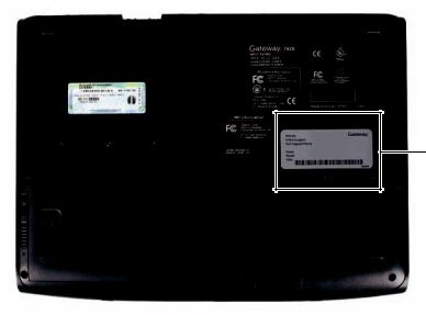
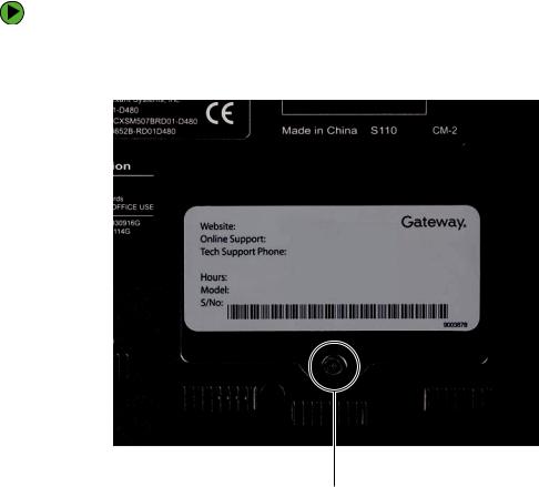
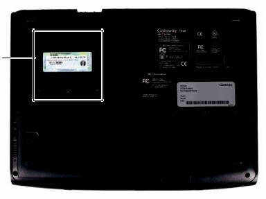
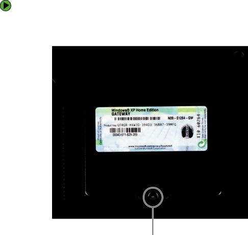
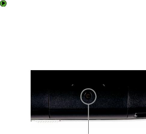
Identifying the notebook model
The label on the bottom of the notebook contains information that identifies the notebook model and its features.
|
|
|
|
|
|
|
|
|
|
|
|
|
|
|
|
|
|
|
|
|
|
|
|
|
|
|
|
|
|
|
|
|
|
|
|
|
|
|
|
|
|
|
|
|
|
|
|
|
|
|
|
|
|
|
|
|
|
|
|
|
|
|
|
|
|
|
|
|
|
|
|
|
|
|
|
|
|
|
|
|
|
|
|
|
|
|
|
|
|
|
|
|
|
|
|
|
|
|
|
|
|
|
|
|
|
|
|
|
|
|
|
|
|
|
|
|
|
|
|
|
|
|
|
|
|
|
|
|
|
|
|
|
|
|
|
|
|
|
|
|
|
|
|
|
|
|
|
|
|
|
|
|
|
|
|
|
|
|
|
|
|
|
|
|
|
|
|
|
|
|
|
|
|
|
|
|
|
|
|
|
|
|
|
|
|
|
|
|
|
|
|
|
|
|
|
|
|
|
|
|
|
|
|
|
|
|
|
|
|
|
|
|
|
|
|
|
|
|
|
|
|
|
|
|
|
|
|
|
|
|
|
|
|
|
|
|
|
|
|
|
|
|
|
|
|
|
|
|
|
|
|
|
|
|
|
|
|
|
|
|
|
|
|
|
|
|
|
|
|
|
|
|
|
|
|
|
|
|
|
|
|
|
|
|
|
|
|
|
|
|
|
|
|
|
|
|
|
|
|
|
|
|
|
|
|
|
|
|
|
|
|
|
|
|
Caution |
|
It is important that you use the correct service guide for the notebook. |
||||||||||||||||||||||||||||||||||||||||||
|
||||||||||||||||||||||||||||||||||||||||||||
|
|
|
|
|
|
Failure to follow the approved tasks for the notebook model may result |
||||||||||||||||||||||||||||||||||||||
|
|
|
|
|
|
|||||||||||||||||||||||||||||||||||||||
|
|
|
|
|
|
in damage to the notebook. |
||||||||||||||||||||||||||||||||||||||
|
|
|
|
|
|
|
|
|
|
|
|
|
|
|
|
|
|
|
|
|
|
|
|
|
|
|
|
|
|
|
|
|
|
|
|
|
|
|
|
|
|
|
|
|
|
|
|
|
|
|
|
|
|
|
|
|
|
|
|
|
|
|
|
|
|
|
|
|
|
|
|
|
|
|
|
|
|
|
|
|
|
|
|
|
|
|
|
|
|
2 |
www.gateway.com |

Identifying components
Identifying components
Use this chart to identify the main components of the notebook. For a complete list of replaceable parts, see “Contents” on page i.
LCD panel assembly (see page 45)
Keyboard cover (see page 28)
Cooling assembly (see page 36)
Keyboard (see page 32)
Palm rest assembly (see page 60)
www.gateway.com |
3 |
Replacing Gateway Notebook Components
Preparing your work space
Before performing maintenance on the notebook, make sure that your work space and the notebook are correctly prepared.
■Wear a grounding (ESD) wrist strap, and use a grounded or dissipative work mat.
■Use a stable and strong table, and make sure that the table top is large enough to hold each component as you remove it.
■Use bright lighting to make part identification easier.
■Keep your work surface free from clutter and dust that may damage components.
■Use a magnetized screwdriver for removing screws.
■When removing components that are attached to the notebook by a cable, unplug the cable before removing the screws, when possible, to avoid damaging the cable.
■As you remove components and screws, lay them toward the rear of your work surface (behind the notebook) or far enough to the side that your arms do not accidentally brush them onto the floor.
■To help keep track of screws, try the following:
■Place each component’s screws in their own section of a parts sorter.
■Place each component’s screws next to the component on your work surface.
■Print the first page of each task, then place the page toward the rear of your work surface. As you remove screws, place the screws in their respective boxes on the page. Where screw measurements are shown, the first number indicates screw head width, and the second number indicates screw length.
■After loosening screws that are deeply recessed in a hole (for example, on the bottom of the base assembly), you can leave the screws in the holes if you place small pieces of masking tape over the hole openings. When reassembling the component, just remove the tape and tighten the screws.
■When you place flat-headed screws on your work surface, stand them on their heads to prevent the screws from rolling off the table.
4 |
www.gateway.com |

Preventing static electricity discharge
Preventing static electricity discharge
Important Before performing maintenance on the notebook, you should read and understand the information in this section.
The components inside your notebook are extremely sensitive to static electricity, also known as electrostatic discharge (ESD).
Warning |
|
To avoid exposure to dangerous electrical voltages and moving parts, |
|
|
turn off your notebook and unplug the power cord, modem cable, and |
|
|
network cable before opening the case. |
Warning |
|
To prevent risk of electric shock, do not insert any object into the vent |
|
||
|
||
|
|
holes of the notebook. |
|
|
|
Before performing maintenance on the notebook, follow these guidelines:
■Avoid static-causing surfaces such as carpeted floors, plastic, and packing foam.
■Remove components from their antistatic bags only when you are ready to use them. Do not lay components on the outside of antistatic bags because only the inside of the bags provide electrostatic protection.
■Always hold components by their edges. Avoid touching the edge connectors. Never slide components over any surface.
■Wear a grounding wrist strap (available at most electronics stores) and attach it to a bare metal part of your workbench or other grounded connection.
■Touch a bare metal surface on your workbench or other grounded object.
Caution |
Some of the procedures in this guide involve removing tape that holds |
|
wires or components. Two types of tape are used in this Gateway |
|
notebook: |
■Mylar, non-conductive tape is typically transparent, with a red or brown tint.
■Conductive tape is typically grey or silver.
If the existing tape cannot be reused, replace it with the same type (conductivity) of tape. Both types of replacement tape should be non-ESD generating tape.
Do not use cellophane tape.
www.gateway.com |
5 |
Replacing Gateway Notebook Components
Preparing the notebook
Warning |
To avoid exposure to dangerous electrical voltages and moving parts, |
|
turn off the notebook, remove the battery, and unplug the power cord, |
|
modem cable, and network cable before opening the case. Replace |
|
the cover before you restore power or reconnect the modem and |
|
network cables. |
|
|
To prepare the notebook for maintenance:
1 Make sure that the CD or DVD drive is empty.
2 Remove any memory cards from the memory card reader.
3 Turn off the notebook and unplug the power cord, modem cable, and network cable.
4 Close the LCD panel.
5 Disconnect all peripheral devices and remove any PC Cards.
6 Remove the battery. For more information, see “Removing the battery” on page 7.
6 |
|
www.gateway.com |
|
Preparing the notebook
Removing the battery
To remove the battery:
1 Turn the notebook over so the bottom is facing up.
2 Slide the battery lock to the unlocked position, then slide and hold the battery release latch.
3 Lift the battery out of the bay.
|
www.gateway.com |
7 |
|
Replacing Gateway Notebook Components
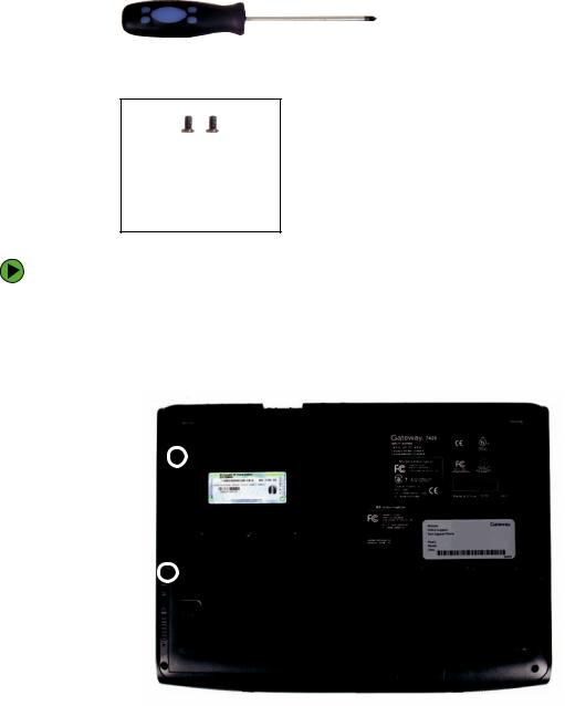
Replacing the memory module in the memory bay
Important Use only memory modules designed for the Gateway 7000 series, M520, MX7000, or NX700.
Important This notebook has two memory modules. One is located in the memory bay. The other is accessible only after removing the palm rest. For more information, see “Replacing the memory module under the palm rest” on page 80.
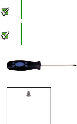
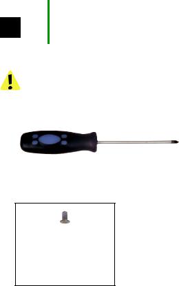
Tools you need to complete this task:
Phillips #0 screwdriver
Screws removed during this task:
1 black (memory bay cover)
8 |
www.gateway.com |
Replacing the memory module in the memory bay
Memory bay
www.gateway.com |
9 |
Replacing Gateway Notebook Components
To replace the memory module:
1 Complete the steps in “Preparing the notebook” on page 6.
2 Remove the memory bay cover screw.
Screw
3 Open the memory bay cover, then remove it.
10 |
www.gateway.com |

Replacing the memory module in the memory bay
4 Gently press outward on the clip at each end of the memory module until the module tilts upward.
Clip |
Clip |
5 Pull the memory module out of the slot.
www.gateway.com |
11 |
Replacing Gateway Notebook Components
6 Hold the replacement module at a 30-degree angle and press it into the empty memory slot. This module is keyed so it can only be inserted in one direction. If the module does not fit, make sure that the notch in the module lines up with the tab in the memory bay.
Important Use only memory modules designed for the Gateway 7000 series, M520, MX7000, or NX700.
7
8
Gently push the module down until it clicks in place.
Replace the memory bay cover, then replace the cover screw.
12 |
|
www.gateway.com |
|
Replacing the IEEE 802.11 Mini PCI card
Replacing the IEEE 802.11 Mini PCI card
Caution By law, only approved wireless modules provided by Gateway, or a Gateway authorized representative, explicitly for the Gateway 7000 series, M520, MX7000, or NX700 may be installed in this notebook.
Caution |
Legal requirements dictate the mini PCI cover plate be in place during |
||
|
|
|
any and all operation of the notebook’s wireless feature. |
|
|
|
|
|
|
|
|
|
|
|
|
Tools you need to complete this task:
Phillips #0 screwdriver
Screws removed during this task:
1 black (mini PCI bay cover)
www.gateway.com |
13 |
Replacing Gateway Notebook Components
Mini PCI
bay
14 |
www.gateway.com |
Replacing the IEEE 802.11 Mini PCI card
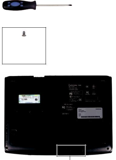
To replace the IEEE 802.11 Mini PCI card:
1 Complete the steps in “Preparing the notebook” on page 6.
2 Remove the mini PCI bay cover screw.
Screw
3 Open the mini PCI bay cover, then remove it.
www.gateway.com |
15 |
Replacing Gateway Notebook Components
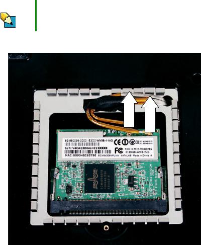
4 Note which antenna cable is attached to the connector labelled MAIN or M, and which antenna cable is attached to the connector labelled AUX or A.
Tips & Tricks Wrap one of the wires with a piece of tape to help remind you.
5 Unplug the two antenna cables.
16 |
www.gateway.com |
Replacing the IEEE 802.11 Mini PCI card
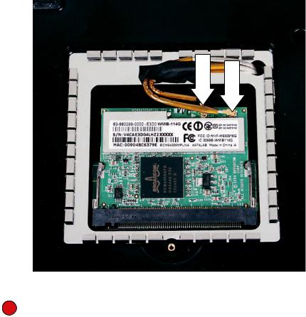
6 Move the antenna cables out of the way, then press outward on the clip at each side of the module until the module tilts upward.
Clip |
Clip |
www.gateway.com |
17 |
Replacing Gateway Notebook Components
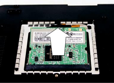
7 Pull the module out of the slot.
8 Hold the new module at a 30-degree angle and press it into the empty slot. This module is keyed so it can only be inserted in one direction. If the module does not fit, make sure that the notch in the module lines up with the tab in the module slot.
9 Move the antenna cables out of the way, then press the module down until it clicks into place.
18 |
www.gateway.com |
Replacing the IEEE 802.11 Mini PCI card
10
11
Reattach the antenna cable to the connectors noted in Step 4.
Replace the wireless network bay cover, then replace the cover screw.
|
www.gateway.com |
19 |
|
Replacing Gateway Notebook Components
Replacing the hard drive kit
Tools you need to complete this task:
Phillips #0 screwdriver
Screws removed during this task:
1 black (hard drive kit)
Hard drive bay
20 |
www.gateway.com |
Replacing the hard drive kit
To replace the hard drive kit:
1 Create a Drivers and Applications Recovery disc using the procedure found in the Using Gateway System Recovery online guide. To access this guide, click Start, All Programs,
System Recovery, then click Recovery Help Manual.
2
3
4
5
Print the Using Gateway System Recovery online guide for use in Step 8.
Back up any data you want to transfer to the new hard drive. For more information, see “Backing up files” in Using Your Computer which has been included on your hard drive. To access this guide, click Start, All Programs, then click Gateway Documentation.
Complete the steps in “Preparing the notebook” on page 6.
Remove the hard drive kit screw.
Screw
www.gateway.com |
21 |

Replacing Gateway Notebook Components
6 Slide the hard drive bay kit to remove it.
Important If your new hard drive does not include the hard drive kit bracket, complete the steps in “Replacing the hard drive in the hard drive kit” on page 23 before proceeding.
7 Slide the new hard drive kit into your notebook, then replace the screw that secures the hard drive kit to your notebook.
8 For instructions on installing Windows, your drivers, and your applications, see the Using Gateway System Recovery online guide you printed in Step 2.
22 |
|
www.gateway.com |
|
Replacing the hard drive in the hard drive kit
Replacing the hard drive in the hard drive kit
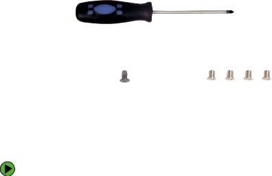
Tools you need to complete this task:
Phillips #0 screwdriver
Screws removed during this task:
1 black (hard drive kit) |
|
4 chrome (hard drive) |
|
|
|
To replace the hard drive in the hard drive kit:
1 Complete the steps in “Preparing the notebook” on page 6.
2 Remove the hard drive kit by following the instructions in “Replacing the hard drive kit” on page 20.
www.gateway.com |
23 |
Replacing Gateway Notebook Components
3 Remove the four screws that secure the hard drive to the hard drive kit bracket.
Screw |
|
|
|
Screw |
|
|
Screw |
|
|
|
Screw |
|
|
24 |
www.gateway.com |
Replacing the hard drive in the hard drive kit
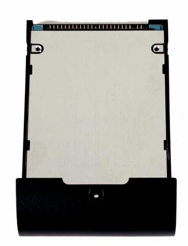
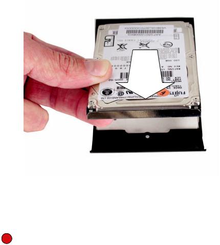
4 Remove the bracket from the old drive.
5 Insert the new drive into the bracket with the label side up and so the screw holes line up.
6 Replace the four screws that secure the bracket to the drive.
7
|
www.gateway.com |
25 |
|
Replacing Gateway Notebook Components
Replacing the CD or DVD drive
Tools you need to complete this task:
Phillips #0 screwdriver
Screws removed during this task:
2 black (CD or DVD drive)
To replace the CD or DVD drive:
1 Complete the steps in “Preparing the notebook” on page 6.
2 Turn the notebook over so the bottom is facing up.
3 Remove the two CD or DVD drive screws.
Screw 
Screw 
26 |
www.gateway.com |
 Loading...