


MG1
SERVICEGUIDE
®

Revision History
Please refer to the table below for the updates made on the MG1 service guide.
Date Chapter Updates
Service guide files and updates are available on the ACER/CSD web. For more information, refer to http://csd.acer.com.tw
Copyright
© 2008 Gateway, Inc. All rights reserved. Gateway, Gateway Country, the Gateway stylized logo, and the black-and-white spot design are
trademarks or registered trademarks of Gateway, Inc. in the United States and other countries. All other brands and product names are
trademarks or registered trademarks of their respective companies.
PRINTED IN TAIWAN

Contents
Chapter 1: System specifications . . . . . . . . . . . . . . . . . . . . . . . . . . . . 1
Preface . . . . . . . . . . . . . . . . . . . . . . . . . . . . . . . . . . . . . . . . . . . . . . . . . . . . . . . . . 2
Conventions . . . . . . . . . . . . . . . . . . . . . . . . . . . . . . . . . . . . . . . . . . . . . . 2
General information . . . . . . . . . . . . . . . . . . . . . . . . . . . . . . . . . . . . . . . 2
Features . . . . . . . . . . . . . . . . . . . . . . . . . . . . . . . . . . . . . . . . . . . . . . . . . . . . . . . . 2
System block diagram . . . . . . . . . . . . . . . . . . . . . . . . . . . . . . . . . . . . . . . . . . . . 5
Hardware specifications and configurations . . . . . . . . . . . . . . . . . . . . . . . . 6
CPU . . . . . . . . . . . . . . . . . . . . . . . . . . . . . . . . . . . . . . . . . . . . . . . . . . . . . . 6
Controllers . . . . . . . . . . . . . . . . . . . . . . . . . . . . . . . . . . . . . . . . . . . . . . . . 6
BIOS . . . . . . . . . . . . . . . . . . . . . . . . . . . . . . . . . . . . . . . . . . . . . . . . . . . . . 7
Memory . . . . . . . . . . . . . . . . . . . . . . . . . . . . . . . . . . . . . . . . . . . . . . . . . . 7
Hard Disk Drive . . . . . . . . . . . . . . . . . . . . . . . . . . . . . . . . . . . . . . . . . . . 8
Optical drive . . . . . . . . . . . . . . . . . . . . . . . . . . . . . . . . . . . . . . . . . . . . . . 8
LCD . . . . . . . . . . . . . . . . . . . . . . . . . . . . . . . . . . . . . . . . . . . . . . . . . . . . . . 8
Inverter . . . . . . . . . . . . . . . . . . . . . . . . . . . . . . . . . . . . . . . . . . . . . . . . . . 8
Video subsystem . . . . . . . . . . . . . . . . . . . . . . . . . . . . . . . . . . . . . . . . . . 8
Keyboard . . . . . . . . . . . . . . . . . . . . . . . . . . . . . . . . . . . . . . . . . . . . . . . . . 9
Pointing device . . . . . . . . . . . . . . . . . . . . . . . . . . . . . . . . . . . . . . . . . . . . 9
Memory card reader . . . . . . . . . . . . . . . . . . . . . . . . . . . . . . . . . . . . . . 10
ExpressCard . . . . . . . . . . . . . . . . . . . . . . . . . . . . . . . . . . . . . . . . . . . . . 10
Audio . . . . . . . . . . . . . . . . . . . . . . . . . . . . . . . . . . . . . . . . . . . . . . . . . . . 10
Wired LAN . . . . . . . . . . . . . . . . . . . . . . . . . . . . . . . . . . . . . . . . . . . . . . . 11
Bluetooth . . . . . . . . . . . . . . . . . . . . . . . . . . . . . . . . . . . . . . . . . . . . . . . . 11
Wireless LAN . . . . . . . . . . . . . . . . . . . . . . . . . . . . . . . . . . . . . . . . . . . . . 11
Modem . . . . . . . . . . . . . . . . . . . . . . . . . . . . . . . . . . . . . . . . . . . . . . . . . . 12
USB . . . . . . . . . . . . . . . . . . . . . . . . . . . . . . . . . . . . . . . . . . . . . . . . . . . . . 12
Buttons/Indicators/Ports . . . . . . . . . . . . . . . . . . . . . . . . . . . . . . . . . . 13
Fingerprint reader . . . . . . . . . . . . . . . . . . . . . . . . . . . . . . . . . . . . . . . . 13
Camera . . . . . . . . . . . . . . . . . . . . . . . . . . . . . . . . . . . . . . . . . . . . . . . . . . 13
Fans . . . . . . . . . . . . . . . . . . . . . . . . . . . . . . . . . . . . . . . . . . . . . . . . . . . . 14
Battery . . . . . . . . . . . . . . . . . . . . . . . . . . . . . . . . . . . . . . . . . . . . . . . . . . 14
Power supply . . . . . . . . . . . . . . . . . . . . . . . . . . . . . . . . . . . . . . . . . . . . 15
Power savings . . . . . . . . . . . . . . . . . . . . . . . . . . . . . . . . . . . . . . . . . . . 15
Notebook product tour . . . . . . . . . . . . . . . . . . . . . . . . . . . . . . . . . . . . . . . . . . 16
Front . . . . . . . . . . . . . . . . . . . . . . . . . . . . . . . . . . . . . . . . . . . . . . . . . . . . 16
Left . . . . . . . . . . . . . . . . . . . . . . . . . . . . . . . . . . . . . . . . . . . . . . . . . . . . . 16
Right . . . . . . . . . . . . . . . . . . . . . . . . . . . . . . . . . . . . . . . . . . . . . . . . . . . . 17
Back . . . . . . . . . . . . . . . . . . . . . . . . . . . . . . . . . . . . . . . . . . . . . . . . . . . . 18
Bottom . . . . . . . . . . . . . . . . . . . . . . . . . . . . . . . . . . . . . . . . . . . . . . . . . . 19
Keyboard area . . . . . . . . . . . . . . . . . . . . . . . . . . . . . . . . . . . . . . . . . . . 20
LCD panel . . . . . . . . . . . . . . . . . . . . . . . . . . . . . . . . . . . . . . . . . . . . . . . 21
Using the status indicators . . . . . . . . . . . . . . . . . . . . . . . . . . . . . . . . 22
Using the keyboard . . . . . . . . . . . . . . . . . . . . . . . . . . . . . . . . . . . . . . . 23
Using the optional fingerprint reader . . . . . . . . . . . . . . . . . . . . . . . 25
i

Contents
Using the EZ Pad touchpad . . . . . . . . . . . . . . . . . . . . . . . . . . . . . . . . 30
Using the optional multimedia panel . . . . . . . . . . . . . . . . . . . . . . . . 32
Using the optional webcam . . . . . . . . . . . . . . . . . . . . . . . . . . . . . . . . 33
Chapter 2: System utilities. . . . . . . . . . . . . . . . . . . . . . . . . . . . . . . . .37
BIOS Setup Utility . . . . . . . . . . . . . . . . . . . . . . . . . . . . . . . . . . . . . . . . . . . . . . . . 38
Navigating the BIOS Setup Utility . . . . . . . . . . . . . . . . . . . . . . . . . . . 38
BIOS Setup Utility screens . . . . . . . . . . . . . . . . . . . . . . . . . . . . . . . . . . 39
BIOS flash utility . . . . . . . . . . . . . . . . . . . . . . . . . . . . . . . . . . . . . . . . . . . . . . . . . 48
Removing a password lock . . . . . . . . . . . . . . . . . . . . . . . . . . . . . . . . . . . . . . . 49
Removing a HDD password lock . . . . . . . . . . . . . . . . . . . . . . . . . . . . 49
Removing a Supervisor password lock . . . . . . . . . . . . . . . . . . . . . . 49
Chapter 3: Replacing notebook components . . . . . . . . . . . . . . . . . .51
Preventing static electricity discharge . . . . . . . . . . . . . . . . . . . . . . . . . . . . .52
Tape . . . . . . . . . . . . . . . . . . . . . . . . . . . . . . . . . . . . . . . . . . . . . . . . . . . . . 52
Preparing your work space . . . . . . . . . . . . . . . . . . . . . . . . . . . . . . . . . . . . . . . 53
Tools required . . . . . . . . . . . . . . . . . . . . . . . . . . . . . . . . . . . . . . . . . . . . . . . . . . . 54
Preparing the notebook . . . . . . . . . . . . . . . . . . . . . . . . . . . . . . . . . . . . . . . . . . 55
Removing the battery . . . . . . . . . . . . . . . . . . . . . . . . . . . . . . . . . . . . . 55
Adding or replacing memory modules . . . . . . . . . . . . . . . . . . . . . . . . . . . . . 56
Replacing the main cooling assembly . . . . . . . . . . . . . . . . . . . . . . . . . . . . . .58
Replacing the processor . . . . . . . . . . . . . . . . . . . . . . . . . . . . . . . . . . . . . . . . . . 61
Replacing the IEEE 802.11 wireless card . . . . . . . . . . . . . . . . . . . . . . . . . . . . 63
Replacing the CMOS battery . . . . . . . . . . . . . . . . . . . . . . . . . . . . . . . . . . . . . .66
Replacing the hard drive . . . . . . . . . . . . . . . . . . . . . . . . . . . . . . . . . . . . . . . . . 69
Replacing the DVD drive . . . . . . . . . . . . . . . . . . . . . . . . . . . . . . . . . . . . . . . . . . 73
Replacing the keyboard cover . . . . . . . . . . . . . . . . . . . . . . . . . . . . . . . . . . . .76
Replacing the keyboard . . . . . . . . . . . . . . . . . . . . . . . . . . . . . . . . . . . . . . . . . . 79
Replacing the inverter . . . . . . . . . . . . . . . . . . . . . . . . . . . . . . . . . . . . . . . . . . . 82
Replacing the webcam . . . . . . . . . . . . . . . . . . . . . . . . . . . . . . . . . . . . . . . . . . . 85
Replacing the lid latches . . . . . . . . . . . . . . . . . . . . . . . . . . . . . . . . . . . . . . . . . 88
Replacing the LCD assembly . . . . . . . . . . . . . . . . . . . . . . . . . . . . . . . . . . . . . .91
Replacing the LCD panel . . . . . . . . . . . . . . . . . . . . . . . . . . . . . . . . . . . . . . . . . . 94
Replacing the LCD panel hinges . . . . . . . . . . . . . . . . . . . . . . . . . . . . . . . . . . .98
Replacing the LCD assembly lid . . . . . . . . . . . . . . . . . . . . . . . . . . . . . . . . . . 102
Replacing the palm rest . . . . . . . . . . . . . . . . . . . . . . . . . . . . . . . . . . . . . . . . .104
Replacing the touchpad board . . . . . . . . . . . . . . . . . . . . . . . . . . . . . . . . . . .108
Replacing the touchpad button board . . . . . . . . . . . . . . . . . . . . . . . . . . . .112
Replacing the fingerprint reader . . . . . . . . . . . . . . . . . . . . . . . . . . . . . . . . .115
Replacing the Bluetooth module . . . . . . . . . . . . . . . . . . . . . . . . . . . . . . . . .118
Replacing the modem . . . . . . . . . . . . . . . . . . . . . . . . . . . . . . . . . . . . . . . . . . .121
Replacing the speakers . . . . . . . . . . . . . . . . . . . . . . . . . . . . . . . . . . . . . . . . . .125
Replacing the system board and VGA cooling assembly . . . . . . . . . . . . 128
ii

www.gateway.com
Replacing the modem jack/USB board . . . . . . . . . . . . . . . . . . . . . . . . . . . 136
Replacing the fan(s) . . . . . . . . . . . . . . . . . . . . . . . . . . . . . . . . . . . . . . . . . . . . 139
Chapter 4: Troubleshooting. . . . . . . . . . . . . . . . . . . . . . . . . . . . . . . 143
Diagnosing problems . . . . . . . . . . . . . . . . . . . . . . . . . . . . . . . . . . . . . . . . . . . 144
System test procedures . . . . . . . . . . . . . . . . . . . . . . . . . . . . . . . . . . . . . . . . . 144
Testing the optical drive . . . . . . . . . . . . . . . . . . . . . . . . . . . . . . . . . 144
Testing the keyboard or auxiliary input device . . . . . . . . . . . . . 145
Testing the memory . . . . . . . . . . . . . . . . . . . . . . . . . . . . . . . . . . . . . 145
Testing the power system . . . . . . . . . . . . . . . . . . . . . . . . . . . . . . . . 145
Testing the touchpad . . . . . . . . . . . . . . . . . . . . . . . . . . . . . . . . . . . . 147
Power-On Self-Test (POST) error message . . . . . . . . . . . . . . . . . . . . . . . . 147
Index of error messages . . . . . . . . . . . . . . . . . . . . . . . . . . . . . . . . . . . . . . . . 148
Error codes . . . . . . . . . . . . . . . . . . . . . . . . . . . . . . . . . . . . . . . . . . . . . 148
Error messages . . . . . . . . . . . . . . . . . . . . . . . . . . . . . . . . . . . . . . . . . 148
No-beep error messages . . . . . . . . . . . . . . . . . . . . . . . . . . . . . . . . . 150
Phoenix BIOS beep codes . . . . . . . . . . . . . . . . . . . . . . . . . . . . . . . . . . . . . . . 151
Symptom-to-FRU error messages . . . . . . . . . . . . . . . . . . . . . . . . . . . . . . . . 156
LCD . . . . . . . . . . . . . . . . . . . . . . . . . . . . . . . . . . . . . . . . . . . . . . . . . . . . 156
Power . . . . . . . . . . . . . . . . . . . . . . . . . . . . . . . . . . . . . . . . . . . . . . . . . . 156
ExpressCard . . . . . . . . . . . . . . . . . . . . . . . . . . . . . . . . . . . . . . . . . . . . 157
Memory . . . . . . . . . . . . . . . . . . . . . . . . . . . . . . . . . . . . . . . . . . . . . . . . 157
Sound . . . . . . . . . . . . . . . . . . . . . . . . . . . . . . . . . . . . . . . . . . . . . . . . . . 157
Power management . . . . . . . . . . . . . . . . . . . . . . . . . . . . . . . . . . . . . 157
Devices . . . . . . . . . . . . . . . . . . . . . . . . . . . . . . . . . . . . . . . . . . . . . . . . . 158
Keyboard and touchpad . . . . . . . . . . . . . . . . . . . . . . . . . . . . . . . . . 158
Modem . . . . . . . . . . . . . . . . . . . . . . . . . . . . . . . . . . . . . . . . . . . . . . . . . 159
Intermittent problems . . . . . . . . . . . . . . . . . . . . . . . . . . . . . . . . . . . . . . . . . . 159
Undetermined problems . . . . . . . . . . . . . . . . . . . . . . . . . . . . . . . . . . . . . . . . 159
Chapter 5: Connector locations. . . . . . . . . . . . . . . . . . . . . . . . . . . . 161
System board top connectors . . . . . . . . . . . . . . . . . . . . . . . . . . . . . . . . . . . 162
System board bottom connectors . . . . . . . . . . . . . . . . . . . . . . . . . . . . . . . . 162
Chapter 6: FRU (Field-Replaceable Unit) list . . . . . . . . . . . . . . . . . 163
Introduction . . . . . . . . . . . . . . . . . . . . . . . . . . . . . . . . . . . . . . . . . . . . . . . . . . . 164
Exploded diagram . . . . . . . . . . . . . . . . . . . . . . . . . . . . . . . . . . . . . . . . . . . . . . 165
Notebook chassis . . . . . . . . . . . . . . . . . . . . . . . . . . . . . . . . . . . . . . . . 165
Notebook LCD panel . . . . . . . . . . . . . . . . . . . . . . . . . . . . . . . . . . . . . 166
FRU list . . . . . . . . . . . . . . . . . . . . . . . . . . . . . . . . . . . . . . . . . . . . . . . . . . . . . . . . 167
Appendix A: Model definition and configuration . . . . . . . . . . . . . 173
Appendix B: Test compatible components . . . . . . . . . . . . . . . . . . . 175
Introduction . . . . . . . . . . . . . . . . . . . . . . . . . . . . . . . . . . . . . . . . . . . . . . . . . . . 176
iii

Contents
Microsoft® Windows® Vista Environment Test . . . . . . . . . . . . . . . . . . . . 176
Appendix C: Online support information . . . . . . . . . . . . . . . . . . . 179
iv

CHAPTER 1
System specifications
• Preface
• Features
• System block diagram
• Hardware specifications and configurations
• Notebook product tour
1

Preface
Conventions
The following conventions are used in this manual:
Indicates a potential for personal injury.
Caution
Indicates a potential loss of data or damage to equipment.
Important
Indic ates information that is important to know for the proper completion of a
procedure, choice of an option, or completing a task.
General information
Before using this information and the product it supports, read the following general
information.
This service guide provides you with all technical information relating to the basic
configuration decided for Acer’s global product offering. To better fit local market
requirements and enhance product competitiveness, your regional office may
decided to extend the functionality of a machine (such as add-on cards, modems, or extra
memory capabilities). These localized features not
guide. In such cases, contact your regional offices or the responsible personnel/channel
to provide you with further technical details.
When ordering FRU parts: Check the most up-to-date information available on your
regional web or channel. If, for whatever reason, a part number change is made, it may
not be noted in this printed service guide.
Acer-authorized Service Providers: You r A cer o ffi ce may h ave a different part number
code to those given in the FRU list of this printed service guide. You use the list
provided by your regional Acer office to order FRU parts for repair and service of customer
machines.
CHAPTER 1: System specifications
Features
2
Platform
•
®
Merom or Pentium processor (1.46GHz to 2.80GHz or above) with
800/667/533 MHz FSB.
Core Logic: Intel GM45/GL40 Northbridge, Intel ICH9M/ICH9ME Southbridge
®
, Realtek, Marvell, or Foxconn IEEE1394 a/b/g/n
Intel
System Memory
• Dual-Channel DDR2 SDRAM support
Up to 2 GB of DDR2 533/667 MHz memory, upgradeable to 4 GB using two SO-DIMM
modules

www.gateway.com
Display and graphics
• 17" WUXGA/WSXGA TFT LCD display panel
VGA Memory:
XXX
VGA Controller:
XXX
Dual independent display support
16.7 million colors
MPEG-2/DVD hardware-assisted capability (acceleration) <Please verify>
MPEG-2/DVD decoding (for selected models) <Please verify>
WMV9 (VC-1) support (acceleration) <Please verify>
WMV9 (VC-1) and H.264 (AVC) decoding (for selected models) <Please verify>
HDMI™ (High-Definition Multimedia Interface) with HDCP (High-bandwidth Digital
Content Protection) support
Storage subsystem
• Industry standard 2.5” 60–120GB 9.5mm height hard disk drive
Optical drive options:
Blu-ray Disc™/DVD-Super Multi double-layer drive
DVD-Super Multi double-layer drive
DVD/CD-RW combo drive
5-in-1 card reader, supporting Secure Digital™ (SD), MultiMediaCard (MMC),
Memory Stick
®
(MS), Memory Stick PRO™ (MS PRO), xD-Picture Card™ (xD)
Input devices
• 103-key keyboard, 2.5 mm (minimum) key travel
• Twelve function keys, four cursor keys, two Windows
• Touchpad pointing device
• Media keys on optional multimedia panel
Audio
•
•
•
•
Communication
•
•
•
LAN: 10/100 Ethernet
Modem: 56K ITU V.92 ready Fax/Modem
2.0+EDR (Enhanced Data Rate)
®
keys
3

I/O Ports and devices
•
•
• Modem (RJ11) (optional)
• Ethernet (RJ45)
• IEEE1394
• eSATA
• Headphone/SPDIF Audio Out
• Microphone in
• DC in jack for AC adapter
ExpressCard™/54 slot
Fingerprint reader (optional)
5-in-1 card reader (SD™, MMC, MS, MS PRO, xD)
HDMI™ port with HDCP support (optional)
Kensington lock slot
Environment
•
• Operating: 32 °F to 90 °F (0 °C to 35 °C)
Non-operating: -4 °F to 140 °F (-20 °C to 60 °C)
Humidity (non-condensing):
Operating: 10% to 90%
Non-operating: 5% to 95%
4

System block diagram
5
Hardware specifications and configurations
CPU
Item Specification
CPU type Intel Merom Core Duo and Merom-Lite
Core logic Intel GM45/GL40 + ICH9M/ICH9ME
CPU package Socket-P, µFCPGA
CPU core voltage <Please provide>
Controllers
Item Controller
Core logic Intel GM45/GL40/PM45 + ICH9M/ICH9ME
■
VGA
Intel Crestline-GM
■
Nvidia NV8E-GT/NB9E-GT
LAN
■
RealTek RTL8111C-GR
■
Marvell 88E8057
USB 2.0 <Please provide>
Super I/O controller <Please provide>
Modem Agere Delphi AM5 (MDC 1.5 form factor)
Bluetooth <Please provide>
Wireless 802.11
■
Foxconn T60H928
■
Intel WiFi Link 5100
■
Intel Golan
■
Intel Kedron
■
Marvell WN6500M
■
Marvell WN6300M
■
Realtek RTL8187
ExpressCard <Please provide>
Memory Card Reader RTS5158
Audio Codec
■
Conexant CX2056-15Z
■
SigmaTel STAC9205
6

BIOS
Item Specification
BIOS vendor Phoenix
BIOS Version
■
■
9C.XX
94.XX
BIOS ROM type <Please provide>
BIOS ROM size <Please provide>
BIOS package <Please provide>
Supported protocols <Please Verify>
■
ACPI 1.0b/2.0/3.0 compliance
■
PCI 2.2 or later
■
System/HDD Password Security Control
■
INT 13H Extensions
■
PnP BIOS 1.0a
■
SMBIOS 2.4 or later
■
BIOS Boot Specification
■
Simple Boot Flag 1.0
■
Boot Block
■
PCI Bus Power Management Interface Specification
■
USB Specification 1.1/2.0
■
IEEE 1394 1.0
■
USB/1394 CD-ROM Boot Up support
■
PC Card Standard 1995 (PCMCIA 3.0 Compliant Device)
■
IrDA 1.0
■
Support HD audio
■
WfM 2.0, PXE 2.1
■
Preboot Execution Environment (PXE) 2.1
■
Boot Integrity Service Application Program Interface (BIS) 1.0
■
PC2002/2005 compliant
■
Intel Enhanced Speedstep Technology
■
ASF 2.0
■
TPM v1.2
■
AHCI support
■
iAMT 4.0 or later (for Intel platform)
BIOS password control Manually set Supervisor and User passwords.
Memory
Item Specification
Cache controller <Please provide>
Cache size <Please provide>
Item Specification
Memory controller Built-in
Memory size 0 MB (no on-board memory)
SO-DIMM socket number 2 sockets
7

CHAPTER 1: System specifications
Item Specification
Supports memory size per
socket
Supports maximum
memory size
Supports SO-DIMM type
Supports SO-DIMM Speed
Supports SO-DIMM
voltage
Supports SO-DIMM
package
Memory module
combinations
Hard Disk Drive
Optical drive
■
2GB per SO-DIMM
■
4GB per SO-DIMM
■
4GB
■
8GB
■
DDR 2 Synchronous DRAM
■
DDR 3 Synchronous DRAM
■
533/667MHz DDR 2
■
800/1066MHz DDR 3
<Please provide>
200-pin SO-DIMM
You can install memory modules in any combinations as long as they match the above
specifications.
Information not available at time of printing
Information not available at time of printing
LCD
Information not available at time of printing
Inverter
Information not available at time of printing
Video subsystem
Item Specification
Chipset
Memory size
■
Intel Crestline-GM GMZ X3100
■
Intel GM45
■
Nvidia NB8E-GT
■
Nvidia NB9E-GT
■
Intel shared memory
■
Nvidia 512MB or 1GB
8

Item Specification
www.gateway.com
Features <Please Verify>
■
Unified Shader Architecture
■
Support Microsoft® DirectX® 10 Shader Model 4
■
Geometry Instancing 2.0
■
SGI OpenGL® 2.0 optimizations and support
■
Adaptive PCI Express interface
■
High efficiency integrated adaptable and programmable video processor (VP2)
■
Integrated Bit Stream Processor (BSP)
■
NVIDIA PureVideo/Pure Video HD technology
■
Industry video codec standard hardware acceleration
■
Advanced Spatial Temporal De-Interlacing
■
Vibrant Color Temperature Correction
■
LCD Overdrive
■
High-Quality Real-Time video recording
■
Best quality 10-bit display pipeline
■
NVIDIA nView Multi Display Technology
■
SmartDimmer Technology
■
Integrated HDMI support
■
Support for integrated HDCP
■
NVIDIA Digital Vibrance Control Technology
■
Integrate HDTV encoder
■
Dual 400MHz RAMDACs
Core voltage <Please provide>
Keyboard
Item Specification
Keyboard controller Winbond 8763
Total number of keypads 1032-key
Windows logo key Yes
Internal & external
Plug USB keyboard to the USB port directly
keyboard work
simultaneously
Pointing device
Item Specification
Ty pe Synaptics 372 Touchpad
Buttons Left/Right
Scrolling Scroll zone on right side of touchpad
9

CHAPTER 1: System specifications
Memory card reader
Item Specification
Controller RTS5158
Cards supported Support 5-in-1 card reader (MMC, MS, MS-pro, SD, and xD)
Compliancy <Please Verify>
■
Complies to SDIO Host Interface Specification Rev 1.0
■
Supports MMC, MMCplus, SD Memory, and SDIO cards
■
SDIO Version 1.10 compliant with High-Speed Mode
■
SD Host Interface Specification v1.0
■
SD Host Interface Specification v2.0
■
SD HC (High Capacity SD memory card)
■
Supports SD memory card, with CPRM security
■
Complies to MultiMediaCard™ Version 4.0
■
Supports Memory Stick™ and MS PRO media cards
■
Supports xD-Picture™ card and SmartMedia™ cards
ExpressCard
Item Specification
Controller <Please provide>
Supports card type Type 54
Number of slots One
Access location Right panel
Audio
Item Specification
Audio Controller SigmaTel STAC9205
Audio onboard or optional Built-in
Mono or Stereo Stereo
Resolution
Compatibility
Sampling rate
Internal microphone With optional webcam
Conexant CX2056-15Z
■
Ten DAC channels support 16/20/24-bit PCM format for 7.1 sound playback, plus 2
channels of independent stereo sound output (multiple streaming) through the front
panel output
■
Two stereo ADCs support 16/20/24-bit PCM format, one for stereo microphone, one for
legacy mixer recording
■
HD Audio
■
All DACs supports 44.1/48/96/192 kHz sample rate
■
All ADCs support 44.1/48/96 kHz sample rate
■
Two independent 16/20/24-bit S/PDIF-OUT converters support 44.1/48/96/192 kHz
sample rate, one for nominal digital audio, the other one for digital audio output to HDMI
transmitter
10

www.gateway.com
Item Specification
Internal speaker/quantity 2 speakers (1.5 W per channel)
Features
■
97 dB SNR DACs & 90 dB SNR ADCs
■
Enable VoIP function
■
Subwoofer support
Wired LAN
Item Specification
LAN chipset RealTek RTL8111C-GR
Supports LAN protocol 10/100 Mbps
LAN connector type RJ45
LAN connector location Left side
Features
Marvell 88E8057
■
Integrated 10/10 BASE-T transceiver
■
PCIe v1.1 compliant
■
Wake on LAN support meeting ACPI requirements
Bluetooth
Item Specification
Chipset <Please provide>
Data throughput 2.1 Mbit/s
Protocol Bluetooth 2.0
Interface USB (board level)
Connector type Wireless via Bluetooth protocols
Wireless LAN
Item Specification
Chipset
Data throughput 11~54 Mbps, up to 270 Mbps for Draft-N
■
Foxconn T60H928
■
Intel WiFi Link 5100
■
Intel Golan
■
Intel Kedron
■
Marvell WN6500M
■
Marvell WN6300M
■
Realtek RTL8187
11

CHAPTER 1: System specifications
Item Specification
Protocol
■
IEEE 802.11a
■
IEEE 802.11b
■
IEEE 802.11g
■
IEEE 802.11 Draft-N
Interface PCI bus (mini PCI socket for wireless module)
Modem
Item Specification
Chipset Agere Delphi AM5
Form factor MDC 1.5 form factor
Protocol
Interface RJ11
■
ITU-T V.92, V.90 data mode with auto-fallback to, V.34, V.32terbo, and V.32bis.
■
V.42 LAPM and MNP 2-4 error correction.
■
V.44, V.42bis, and MNP 5 data compression.
■
Send and receive rates up to 14400 bps, support ITU-T V.17, V.29, V.27ter, and V.21 Ch2 fax.
■
TIA/EIA 602 Standard for AT command set, and Fax TIA/EIA 578 Class 1 command set.
USB
Item Specification
Chipset <Please provide>
USB compliancy level 2.0
OHCI USB 1.1 and USB 2.0 host controller
Number of USB ports 3
Location
Serial port function
■
One on the left side
■
Two on the right sid e
Enable/Disable by BIOS Setup
control
12

Buttons/Indicators/Ports
Item Specification
www.gateway.com
Buttons
Indicators
Ports
Fingerprint reader
■
Media control buttons and capacitive volume control on media panel
■
Power button
■
Windows Hotstart (select models only)
■
Wireless on/off switch
■
Wireless on/off
■
Caps Lock
■
Num Lock
■
Hard drive activity
■
Optical drive activity
■
Power
■
Battery charge
■
USB (three)
■
External display (VGA) port
■
Modem (RJ11) (optional)
■
Ethernet (RJ45)
■
IEEE1394
■
eSATA
■
Headphone/SPDIF Audio Out
■
Microphone in
■
DC in jack for AC adapter
■
ExpressCard™/54 slot
■
Fingerprint reader (optional)
■
5-in-1 card reader (SD™, MMC, MS, MS PRO, xD)
■
HDMI™ port with HDCP support (optional)
Item Specification
Model UPEK TCS4BB
Interface 8-bit parallel, SPI
Resolution High-definition 192 × 4 pixel array
Technology CMOS active capacitive pixel-sensing
Power 3.3V
Software Protector Suite QL
Camera
Item Specification
Model Chicony CNF6141
Interface USB 2.0
Resolution 1.3 M pixels (1280 x 1024)
Signal to noise ratio 42 dB
13

CHAPTER 1: System specifications
Item Specification
Sensor CMOS 1/4
Power 5 V
Built-in microphone Yes
LED On/Off
Software Gateway Camera Assistant
Fans
CPU Temperature Fan Speed (rpm) Acoustic Level (dBA)
<Please provide> <Please provide> <Please provide>
Throttling 50%: % is controlled by operating system. Temperature point is 95°C
OS shut down at 100°C; H/W shut down at 105°C
Battery
Item Specification
Vendor
Battery Type Li-ion
Pack capacity 5772mAH—8658mAH
Number of battery cell 6 or 9
Package configuration
Normal voltage 11.1V
Charge voltage 12. 6V (max)
■
Dyna
■
Sanyo
■
Simplo
■
3 cells in series, 2 series in parallel
■
3 cells in series, 3 series in parallel
14

Power supply
Item Specification
www.gateway.com
Vendor
■
■
Delta
Hipro
Input rating 90V AC to 264VAC, 47Hz to 63Hz
Maximum input AC
1.5A (max)
current
Output rating 19V DC, 4.74A to 6.32A, 90W to 120W
Power savings
ACPI mode Power Management
Mech. Off (G3) All devices in the notebook are turned off completely.
Soft Off (G2/S5) OS initiated shutdown. All devices in the notebook are turned off completely.
Working (G0/S0) Individual devices such as the CPU and hard disc may be power managed in this state.
■
Suspend to RAM (S3)
Save to Disk (S4) Also called Hibernation mode. System saves all system states and data onto the disc prior
CPU set power down
■
VGA suspend
■
PCMCIA suspend
■
Audio power down
■
Hard drive power down
■
Optical drive power down
■
Super I/O low power mode
to powering off the whole system.
15

CHAPTER 1: System specifications
Notebook product tour
Important
Case color may vary from that shown in the pictures.
Front
Left
Power indicator
Battery charge indicator
LCD panel release latch
Component Icon Description
Power indicator
Battery charge
indicator
LCD panel release
latch
Wireless network
switch
■
LED on - Notebook is on.
■
LED blinking - Notebook is in Sleep or Hybrid Sleep mode.
■
LED off - Notebook is off.
■
LED blue - Battery is fully charged.
■
LED purple - Battery is charging.
■
LED blinking red - Battery charge is very low.
■
LED solid red - Battery is malfunctioning.
Important: This LED only lights up when your notebook is
connected to AC power or the battery charge is very low.
Press to open the LCD panel.
Turn the optional IEEE 802.11 wireless network radio and
optional Bluetooth radio on or off.
Warning: Radio frequency wireless communication can
interfere with equipment on commercial aircraft. Current
aviation regulations require wireless devices to be turned off
while traveling in an airplane. IEEE 802.11 and Bluetooth
communication devices are examples of devices that provide
wireless communication.
Wireless network switch
16
Kensington lock slot
USB ports
Ventilation fan
DVD drive
Component Icon Description
Kensington ™
lock slot
USB ports Plug USB devices (such as a diskette drive, flash drive, printer,
Secure your notebook to an object by connecting a Kensington
cable lock to this slot.
scanner, camera, keyboard, or mouse) into these ports.

www.gateway.com
Component Icon Description
Right
Ventilation fan Helps cool internal components.
DVD drive Insert CDs or DVDs into this drive.
Memory card reader
Express Card slot
Headphone jack
Microphone jack
Warning: Do not work with the notebook resting on your lap.
If the air vents are blocked, the notebook may become hot
enough to harm your skin.
Caution: Do not block or insert objects into these slots. If these
slots are blocked, your notebook may overheat resulting in
unexpected shutdown or permanent damage to the notebook.
Caution: Provide adequate space around your notebook so air
vents are not obstructed. Do not use the notebook on a bed,
sofa, rug, or other similar surface.
IEEE 1394 p ort
Monitor port
eSATA jack
USB port
Ethernet jack
HDMI out jack
Component Icon Description
Memory card
reader
IEEE 1394 port
(optional)
Express Card slot Insert one Type 54 Express Card into this slot.
Headphone jack Plug amplified speakers or headphones into this jack. The
Microphone jack Plug a microphone into this jack. The built-in microphone is
USB port Plug a USB device (such as a diskette drive, flash drive, printer,
Ethernet jack Plug an Ethernet network cable into this jack. Plug the other
HDMI out jack
(optional)
HDMI Plug an HDMI device, such as a high definition television, into
Insert a memory card from a digital camera, MP3 player, PDA,
or cellular telephone into the memory card reader. The
memory card reader supports Memory Stick®, Memory Stick
Pro®, Mini Secure Digital®, MultiMediaCard™,
RS-MultiMediaCard™, Secure Digital™, and xD-Picture Card™
cards.
Plug an IEEE 1394 (also known as Firewire® or i.Link®) device
(such as a digital camcorder or MP3 player) into this optional
4-pin IEEE 1394 port.
built-in speakers are turned off when speakers or headphones
are plugged into this jack.
turned off while an external microphone is connected.
scanner, camera, keyboard, or mouse) into this port.
end of the cable into a cable modem, DSL modem, or an
Ethernet network jack.
this optional jack.
17

CHAPTER 1: System specifications
Component Icon Description
Back
eSATA jack
(optional)
Monitor port Plug an analog VGA monitor or projector into this port.
Ventilation fan
eSATA Connect an external SATA hard drive to this optional jack.
Power connector
Modem jack
Component Icon Description
Ventilation fan Helps cool internal components.
Warning: Do not work with the notebook resting on your lap.
If the air vents are blocked, the notebook may become hot
enough to harm your skin.
Caution: Do not block or insert objects into these slots. If these
slots are blocked, your notebook may overheat resulting in
unexpected shutdown or permanent damage to the notebook.
Caution: Provide adequate space around your notebook so air
vents are not obstructed. Do not use the notebook on a bed,
sofa, rug, or other similar surface.
Power connector Plug the AC adapter cable into this connector.
Modem jack
(optional)
Plug a dial-up modem cable into this optional jack.
18

Bottom
www.gateway.com
Battery latch
Battery
Online Support:
Tech Support Phone:
Hours:
Model:
S/No:
Battery lock
Customer
care label
Memory bay
Hard drive bay
Component Icon Description
Memory bay Memory modules are located in this bay.
Battery latch Slide to release the battery.
Battery Provides power when the notebook is not plugged into AC power.
Battery lock Slide to unlock the battery.
Customer Care
Includes the Customer Care contact information.
label
Hard drive bay The hard drive(s) is (are) located in this bay.
19

Keyboard area
CHAPTER 1: System specifications
Power button
Speaker Speaker
Keyb oard
Multimedia panel
Status indicators
Fingerprint reader
Touchpad
Component Icon Description
Keyboard Provides all the features of a full-sized, computer keyboard.
Speakers Provide audio output when headphones or amplified speakers
Power button Press to turn the power on or off. You can also configure the
are not plugged in.
power button for Sleep/Resume mode.
Multimedia panel
(optional)
Touchpad Provides all the functionality of a mouse.
Fingerprint reader
(optional)
Status indicators Inform you when a drive is in use or when a button has been
Use to control playback of CDs and DVDs. The panel includes a
capacitive (touch) volume control.
Provides enhanced security.
pressed that affects how the keyboard is used.
20

LCD panel
www.gateway.com
Optional microphone
Optional webcam
Optional webcam status indicator
Component Description
Microphone (optional) Use to talk through when making Voice over Internet
Webcam (optional) Use to let others see who they are communicating with
Webcam status indicator (optional) Turns on when the webcam is turned on.
Protocol (VoIP) calls.
Important: The optional microphone is only available
when purchased with the optional webcam.
when making VoIP calls.
21
CHAPTER 1: System specifications
A
1
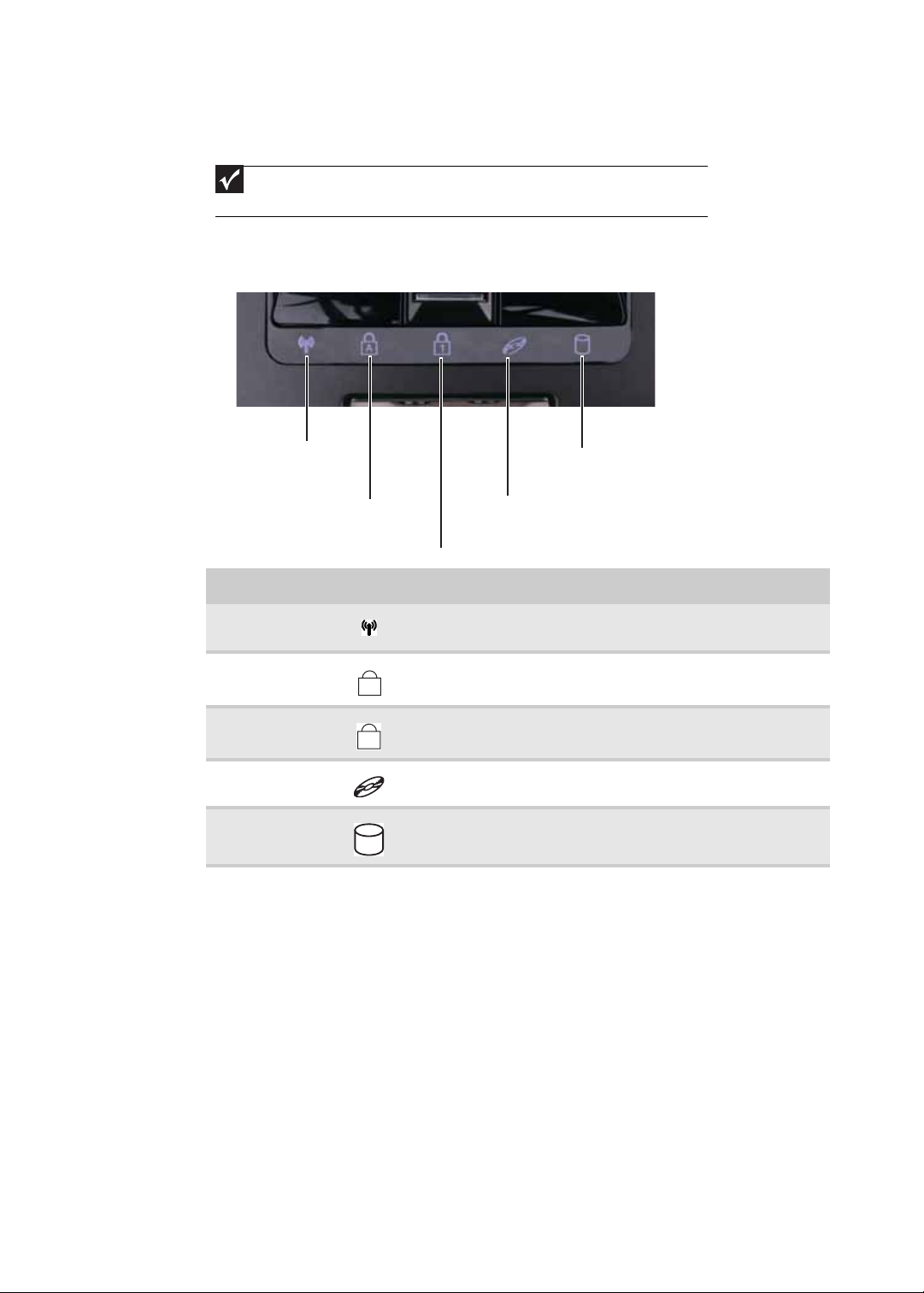
Using the status indicators
Important
If none of the indicators are on, you may need to press FN+F1 to toggle the status
indicators on.
Status indicators inform you when a drive is being used or when a button has been
pressed that affects how the keyboard is used. The status indicators are located below
the touchpad.
Wireless network
Caps lock
Num lock
Indicator Icon Description
Wireless network
Caps lock
Num lock
DVD drive
Hard drive
■
LED on - Optional wireless IEEE 802.11 radio is turned on.
■
LED off - Optional wireless IEEE 802.11 radio is turned off.
■
LED on - Caps lock is turned on.
■
LED off - Caps lock is turned off.
■
LED on - Numeric keypad is turned on.
■
LED off - Numeric keypad is turned off.
■
LED on - Drive is in use.
■
LED off - Drive is not in use.
■
LED blinking - Hard drive is being accessed.
■
LED off - Hard drive is not being accessed.
Hard drive
DVD drive
22

Using the keyboard
Your notebook features a full-size keyboard that functions the same as a desktop
computer keyboard. Many of the keys have been assigned alternate functions, including
shortcut keys for Windows and function keys for specific system operations.
FN
key
Windows key
Key types
The keyboard has several different types of keys. Some keys perform specific actions when
pressed alone and other actions when pressed in combination with another key.
Function keys/ System keys
www.gateway.com
Application
key
Arrow keys
Navigation keys
Numeric
keypad
Key type Icon Description
Function keys Press these keys labeled F1 to F12 to perform actions in
System keys Press these colored keys in combination with the F
Navigation keys Press these keys to move the cursor to the beginning of a line,
Numeric keypad Use these keys to type numbers.
FN key Press the FN key in combination with a colored system key to
Windows key Press this key to open the Windows Start menu. This key can
Application key Press this key for quick access to shortcut menus and help
Arrow keys Press these keys to move the cursor up, down, right, or left.
programs. For example, pressing F1 may open help.
Each program uses different function keys for different
purposes. See the program documentation to find out more
about the function key actions.
N key to
perform specific actions.
to the end of a line, up the page, down the page, to the
beginning of a document, or to the end of a document.
perform a specific action.
also be used in combination with other keys to open utilities like
F (Search utility), R (Run utility), and E (Computer window).
assistants in Windows.
System key combinations
When you press the FN key and a system key at the same time, your notebook performs
the action identified by the text or icon on the key.
23
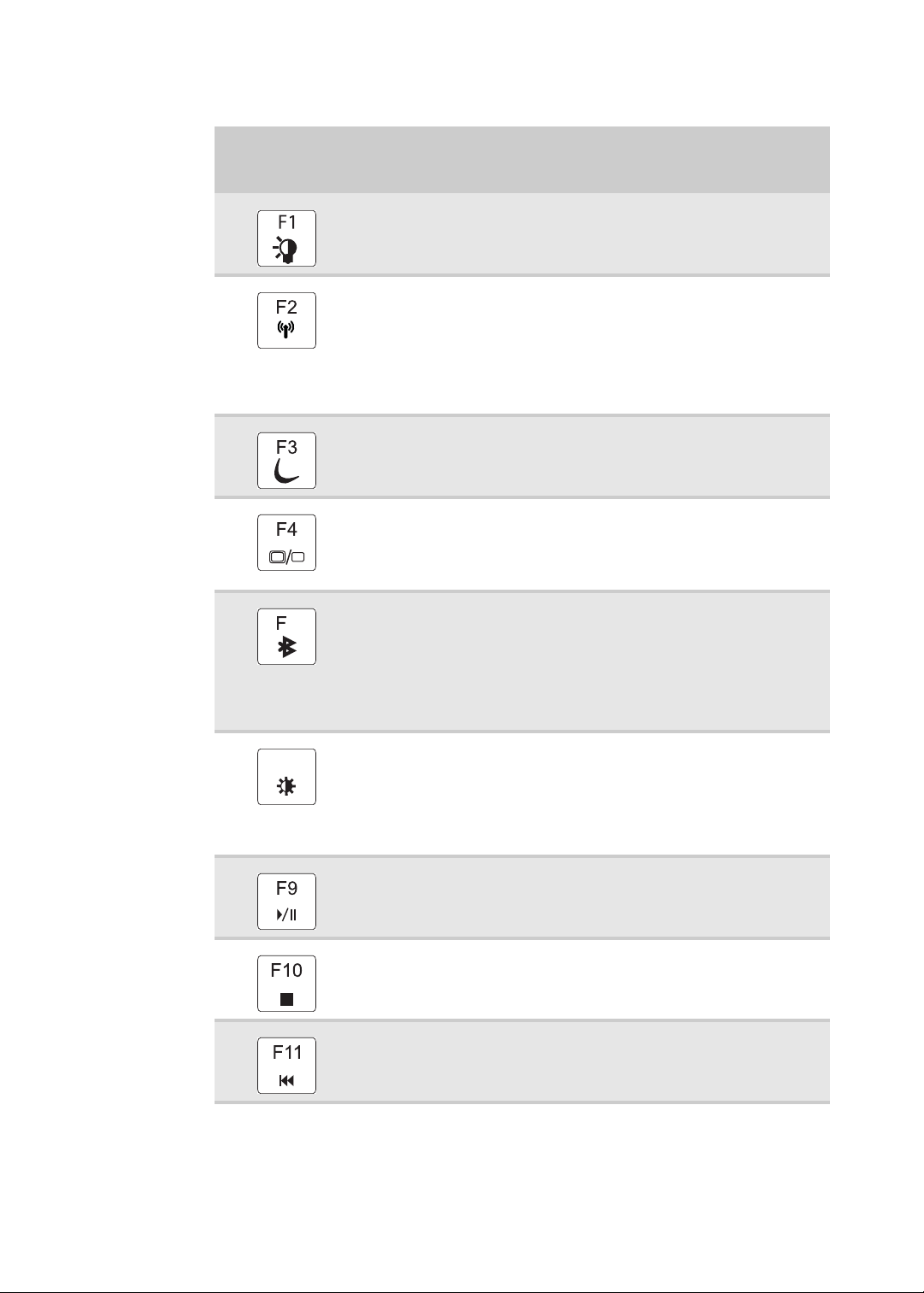
CHAPTER 1: System specifications
Press and hold FN,
then press this
system key...
6
To...
Toggle the status indicators on or off.
Turn the optional IEEE 802.11 wireless network radio on or off.
Warning: Radio frequency wireless communication can interfere with
equipment on commercial aircraft. Current aviation regulations require
wireless devices to be turned off while traveling in an airplane.
IEEE 802.11 communication devices are examples of devices that provide
wireless communication.
Important: The wireless network switch must be in the ON position for
this button to work.
Enter Sleep mode or Hybrid Sleep mode. Press the power button to leave
Sleep mode.
Toggle the notebook display in the following order:
■
The LCD
■
An external monitor or projector (a monitor or projector must be
plugged into the monitor port or HDMI port on your notebook)
■
Both displays at the same time
Turn the optional Bluetooth radio on or off.
Warning: Radio frequency wireless communication can interfere with
equipment on commercial aircraft. Current aviation regulations require
wireless devices to be turned off while traveling in an airplane. Bluetooth
communication devices are examples of devices that provide wireless
communication.
Important: The wireless network switch must be in the ON position for
this button to work.
24
F8
-
Increase the LCD panel brightness above the normal brightest setting.
Use this feature in bright lighting situations, such as outside in bright
+
sunlight.
Press a second time to decrease the brightness below the normal lowest
brightness setting. Use this feature in dim lighting situations.
Press a third time to return the display to the normal brightness setting.
Important: Using this feature will affect battery performance.
Play or pause the CD or DVD.
Stop playing the CD or DVD.
Skip back one CD track or DVD chapter.

www.gateway.com
Press and hold FN,
then press this
system key...
To...
Skip ahead one CD track or DVD chapter.
Increase the brightness of the display.
Decrease the brightness of the display.
Increase volume.
Decrease volume.
Mute the sound. Press the key combination again to restore the sound.
Using the optional fingerprint reader
Your notebook may include a fingerprint reader that provides enhanced security and
convenience. The fingerprint reader is located between the left and right touchpad
buttons.
25

CHAPTER 1: System specifications
Features include:
• Secure logon to Windows and fast user switching between user accounts
• Password bank feature which records and replays passwords used in Windows and
Web-based applications
• A safe or folder for storing encrypted files that only a user with a matching
fingerprint can access
• Boot level security that requires a fingerprint authentication before the system will
boot to Windows
• Scrolling so you can use the fingerprint reader in place of the touchpad
Running the TouchStrip Tutorial
Before using the fingerprint reader the first time, you should run the TouchStrip Tutorial
which teaches you the correct method to use the fingerprint reader.
To run the TouchSt rip Tutorial:
1 Click (Start), All Programs, Protector Suite QL, then click Fingerprint Tutorial.
2 Click Next to proceed through the tutorial.
Enrolling your fingerprints
Before you can use the features of the fingerprint reader, you must enroll your fingerprints
so your notebook can identify you.
To enroll your fingerprints:
1 Click (Start), All Programs, Protector Suite QL, then click User Enrollment.
The Welcome screen opens.
2 Click Next. The Finish screen opens.
3 Select one of the following options, then click Next.
• Enrollment to the biometric device—Select this option to save your
fingerprint to memory in the fingerprint reader. Use this option to prevent
unauthorized use of your notebook even if the hard drive has been removed.
• Enrollment to the hard disk—Select this option to save your fingerprint to
the hard drive. If you plan to enroll more than 21 fingerprints, you must select
this option.
The User Enrollment wizard opens.
26

www.gateway.com
4 If you want to run the TouchStrip Tutorial, leave the Run interactive tutorial check
box selected, then click Next. The TouchStrip Tutorial runs. After you have completed
the tutorial, the Enrollment screen appears.
-ORIf you do not want to run the TouchSt rip Tutorial, click to uncheck the Run
interactive tutorial check box, then click Next. The Enrollment screen appears.
5 Click the button above the finger you are enrolling. A new box appears with three
empty circles in it.
6 Swipe your finger. A sample will be created and is indicated by a fingerprint icon
in one of the circles.
27

CHAPTER 1: System specifications
7 Repeat step Step 6 two more times, then click Next. The Advanced Security screen
appears.
8 Type a password in the Backup password box, type the same password in the
Retype password box, then click Next.
9 Click Finish.
Using the Fingerprint Control Center
The Fingerprint Control Center lets the administrator of the notebook control how the
fingerprint reader is used. You can:
• Add new fingerprints to the database
• Edit or delete fingerprints from the database
• Modify how fingerprints are used for logging onto the notebook
• Modify how the fingerprint reader is used for scrolling
To use the Fingerprint Control Center:
1 Click (Start), All Programs, Protector Suite QL, then click Control Center. The
Fingerprint Control Center opens.
28
2 If you are logged into the notebook with administrator privileges, click Elevate
administrative privileges for user so you can make changes to the settings.

www.gateway.com
3 Click the yellow arrow in front of an option, then click the option or setting you want
to change.
Using the password bank
The password bank stores registrations to your favorite secure Web sites so that you can
access them without having to re-enter your username and password each time you want
to log into the site.
Tip
The password bank also works with many computer programs that require entering
a username and password.
To create a registration for a Web site:
1 Go to the Web site using your Internet browser.
2 Log in using your user name and password.
3 Swipe your already enrolled finger over the sensor. The fingerprint reader menu
opens.
4 Click Register.
5 Click on the dialog box or Web site sign in box.
To log on to a registered Web site:
1 Swipe your already enrolled finger over the sensor. The fingerprint reader menu
opens.
2 Click Registered Sites, then click the Web site you want to log onto.
3 Your Internet browser opens and automatically logs you onto the Web site.
Using the fingerprint reader features
For more information about the fingerprint reader and how to use its features, click
All Programs, Protector Suite QL, then click Help.
(Start),
29

CHAPTER 1: System specifications
Using the EZ Pad touchpad
The EZ Pad™ consists of a touchpad, two buttons, and a scroll zone.
Left button
Scroll zone
Tou ch pa d
Right button
When you move your finger on the touchpad, the pointer (arrow) on the screen moves
in the same direction. You can use the scroll zone to scroll through documents. Use of
the scroll zone may vary from program to program.
You can use the EZ-Pad left and right buttons below the touchpad to select objects.
30

www.gateway.com
To... Do this...
Move the
pointer on the
screen.
Select an object
on the screen.
Start a program
or open a file or
folder.
Access a
shortcut menu
or find more
information
about an object
on the screen.
Move your finger around on
the touchpad. If you run out of
space and need to move the
pointer farther, lift your finger,
move it to the middle of the
touchpad, then continue
moving your finger.
Position the pointer over the
object. Quickly press and
release the left button once.
This action is called clicking.
Position the pointer over the
object. Press the left button
twice in rapid succession. This
action is called double-clicking.
Position the pointer over the
object. Quickly press and
release the right button once.
This action is called
right-clicking.
Move an object
on the screen.
Position the pointer over the
object. Press the left button and
hold it down, then use the
touchpad to move (drag) the
object to the appropriate part
of the screen. Release the
button to drop the object
where you want it.
31

CHAPTER 1: System specifications
Using the optional multimedia panel
Windows Hotstart
Instant On Audio
Instant On Video
Button Description
Windows Hotstart—Turns on the notebook (if turned off) and opens Media Center
(Windows Vista Home Premium or Windows Vista Ultimate) or Windows Media Player
(Windows Vista Home Basic).
Important: You can use this button if the notebook is turned on, turned off, or in
Sleep or Hibernate mode.
Important: You cannot use this button if you are logged on as a guest.
Instant on Audio—Opens Media Center (Windows Vista Home Premium or Windows
Vista Ultimate) or Windows Media Player (Windows Vista Home Basic).
Instant on Video—Opens Media Center (Windows Vista Home Premium or Windows
Vista Ultimate) or the DVD player program (Windows Vista Home Basic).
Play or pause the CD or DVD.
Stop playing the CD or DVD.
Skip back one CD track or DVD chapter.
Capacitive volume control
Mute sound
Skip ahead
Skip back
Play/Pause
Stop
32
Skip ahead one CD track or DVD chapter.
Mute the sound. Press again to restore the sound.
Capacitive volume control—Swipe your finger on the volume sensor strip to change
the volume. To increase volume, move from the – towards the +. To decrease volume,
move from the + towards the –.
Tip:
■
You can start swiping at any point on the strip.
■
The duration of the swipe determines the amount of the change.
■
At the end of this swipe, if you keep your finger on the strip, the volume control
continues to change in the same direction.
■
Tapping on the strip does not change the volume.

Using the optional webcam
You can use the optional webcam with many of the available Internet chat programs to
add video and audio to your chat session. In addition, by using the software included with
the webcam, you can take pictures or create video clips.
www.gateway.com
Webcam
Microphone
Status indicator
33

CHAPTER 1: System specifications
To use the webcam:
1 Click (Start), All Programs, Camera Assistant Software, then click Camera
Assistant Software. The Camera Assistant Toolbar opens.
-ORRight-click (Camera assistant software) on the taskbar, then click Show Toolbar.
The Camera Assistant Toolbar opens.
Button Icon Description
Start camera Turns on the camera and opens the preview screen.
Effects Adds a decoration or border to your picture.
Properties Modifies properties such as zoom, backlight compensation,
Settings Selects the position of the toolbar or modifies the picture,
Help Opens online help.
Important
If you do not see the toolbar, the Auto Hide setting may be turned on. Move
your pointer around the outside of the screen until the toolbar appears.
brightness, and contrast.
video, or audio settings.
34

www.gateway.com
2 Click (Start camera). The Camera Assistant opens.
3 Click one of the following:
Button Icon Description
Snapshot Take a picture of what is currently in the
Video recording Create a video recording.
Audio recording Create an audio recording.
Functions Change a setting or access online help.
Resolution Change the size of the picture.
Mute Turn audio capture on or off.
Effects Add a decoration or border to your picture.
preview screen.
35

CHAPTER 1: System specifications
36

• BIOS Setup Utility
• BIOS flash utility
• Removing a password lock
CHAPTER 2
System utilities
37

BIOS Setup Utility
The BIOS Setup Utility is a hardware configuration program built into the notebook’s BIOS
(Basic Input/Output System). The notebook was shipped already properly configured and
optimized. However, if the user encounters configuration problems, you may need to run
Setup.
Important
Also see Chapter 4 “Troubleshooting” on page 143.
To run the BIOS Setup Utility:
1 Turn on the notebook. You will see Press <F2> to enter Setup at the bottom of
the screen.
2 Press F2. The BIOS Setup Utility opens.
CHAPTER 2: System utilities
Navigating the BIOS Setup Utility
There are six menu options in the BIOS Setup Utility: Information, Main, Advanced, Intel,
Security, Boot, and Exit.
To use the BIOS Setup Utility:
• To choose a menu, use the left ← and right → arrow keys.
• To choose an item, use the up ↑ and down ↓ arrow keys.
• To change the value of a parameter, press F5 or F6.
• A plus sign (+) indicates the item has sub-items. Press ENTER to expand this item.
• Press ESC while you are in any of the menu options to go to the Exit menu.
• In any menu, you can load default settings by pressing F9. You can also press F10
to save any changes made and exit the BIOS Setup Utility.
Important
You can change the value of a parameter if it is enclosed in square brackets.
Navigation keys for a particular menu are shown on the bottom of the screen. Help
for parameters are found in the Item Specific Help part of the screen. Read this
information carefully when making changes to parameter values. System
information differs by model.
38

BIOS Setup Utility screens
Important
The screens shown in this section are for informational purposes only. Screen
information varies by model, features ordered, and location.
Main screen
The Main screen allows the user to set the system time and date as well as view a summary
of your notebook hardware information.
www.gateway.com
Parameter Description
System Time Sets the system time. The hours are displayed in a 24-hour format.
System Date Sets the system date.
System BIOS Version Shows the version of the system BIOS.
CPU Type Shows the type of CPU installed in the notebook.
CPU Speed Shows the speed of the CPU installed in the notebook.
Total Memory Shows the total memory in the notebook.
Slot 1 Memory Shows the memory in slot 1.
Slot 2 Memory Shows the memory in slot 2.
39

CHAPTER 2: System utilities
Advanced screen
The Advanced screen allows the user to configure advanced notebook features.
The table below describes the parameters found on this screen.
Parameter Description Format/Option
Legacy USB Support Specifies if the USB devices
work under MS-DOS or CMOS
SETUP.
Extreme CPU Speed Specifies to speed of a
GExtreme CPU.
SATA Mode Specifies the SATA controller
mode.
Quiet Boot Determines if the Summary
Screen is disabled or enabled.
Enabled: The Gateway logo is
displayed, and the Summary
Screen is not displayed.
Disabled: The Gateway logo is
not displayed and the
Summary Screen is displayed.
Option: Enabled or Disabled
Option: IDE, AHCI, or RAID
Option: Enabled or Disabled
40

www.gateway.com
Security screen
The Security screen contains parameters that help safeguard and protect your notebook
from unauthorized use.
Important
Refer to “Removing a password lock” on page 49 if you need to know how to remove
a Hard Drive or BIOS Password.
The table below describes the parameters in this screen. Settings in boldface are the
.
default and suggested parameter settings.
Parameter Description Option
Supervisor Password Is Shows the setting of the
Supervisor password
User Password Is Shows the setting of the User
password.
Set Supervisor Password Press Enter to set the
supervisor password. When
set, this password protects
the BIOS Setup Utility from
unauthorized access. The user
cannot enter the Setup Utility
without entering this
password.
Set User Password Press Enter to set the user
password. When a user
password i s set, this password
protects the BIOS Setup Utility
from unauthorized changes.
The user can enter the Setup
Utility only and does not have
the right to change the value
of any parameters.
If Password on Boot is
enabled, the user must enter
the user password each time
the notebook is turned on or
wakes from Sleep.
Clear or Set
Clear or Set
41

CHAPTER 2: System utilities
Parameter Description Option
Fixed disk boot sector Write protects the boot sector
on the hard drive to protect
against viruses.
Password on Boot Defines whether a password
is required or not while the
events defined in this group
happened. The sub-options
all require the Supervisor
password for changes and
should be grayed out if the
User password was used to
enter the Setup Utility.
Normal or Write Protect
Disabled or Enabled
Caution
When you are prompted to enter a password, you have three tries before the system
halts. Don’t forget your password. If you forget your password, you may have to return your
notebook to your dealer to reset it.
Setting a Password
Important
You must set a Supervisor password before you can set a User password.
To set the Supervisor password:
1 Press ↑ or ↓ to highlight Set Supervisor Password, then press ENTER. The Set
Supervisor Password box opens.
42
2 Type a password in the Enter New Password field. The password length cannot
exceed eight alphanumeric characters (A-Z, a-z, 0-9). The password is not case
sensitive.
3 Retype the password in the Confirm New Password field.
Caution
Be very careful when typing your password because the characters do not
appear on the screen.

www.gateway.com
4 Press ENTER. After setting the password, the value of Supervisor Password changes
to Set.
5 Optional: you can enable the Password on Boot parameter.
6 When you are done, press F10 to save your password and exit the BIOS Setup Utility
or you can proceed to setting the User password.
To set the User password:
1 Press ↑ or ↓ to highlight Set User Password, then press ENTER. The Set User
Password box opens.
2 Type a password in the Enter New Password field. The password length cannot
exceed eight alphanumeric characters (A-Z, a-z, 0-9). The password is not case
sensitive.
3 Retype the password in the Confirm New Password field.
Caution
Be very careful when typing your password because the characters do not
appear on the screen.
4 Press ENTER. After setting the password, the value of User Password changes to Set.
5 When you are done, press F10 to save your password and exit the BIOS Setup Utility.
Removing a Password
To remove a password:
1 Press ↑ or ↓ to highlight Set Supervisor Password or Set User Password, then
press ENTER. The Set Supervisor Password or Set User Password box opens.
2 Type the current password in the Enter Current Password field, then press ENTER.
3 Press ENTER twice without typing anything in the Enter New Password and
Confirm New Password fields. After removing the password, the value of
Supervisor Password changes to Clear.
4 When you are done, press F10 to save your password and exit the BIOS Setup Utility.
43

CHAPTER 2: System utilities
Changing a Password
To change a password:
1 Press ↑ or ↓ to highlight Set Supervisor Password or Set User Password, then
NTER. The Set Supervisor Password or Set User Password box opens.
press E
2 Type the current password in the Enter Current Password field, then press ENTER.
Important
If you enter an incorrect current password, the screen displays the following.
Press E
NTER, then re-enter the current password.
44
3 Type a password in the Enter New Password field.

www.gateway.com
4 Retype the password in the Confirm New Password field.
Important
If you do not enter the same new password and confirm new password, the
screen displays the following. Press E
confirmation password.
NTER, then re-enter the new password and
5 Press ENTER. The screen displays the following.
6 Press ENTER.
7 When you are done, press F10 to save your password and exit the BIOS Setup Utility.
45

CHAPTER 2: System utilities
Boot
This menu allows the user to decide the order of boot devices to load the operating
system. Bootable devices include the onboard hard disk drive and the optical drive. Follow
the instructions in Item Specific Help to change to boot order of the notebook devices.
Exit
The Exit screen contains options for leaving the BIOS Setup Utility and starting Windows.
The table below describes the options on this screen.
Option Description
Exit Saving Changes Exit the BIOS Setup Utility and save your changes to CMOS.
46
Exit Discarding Changes Exit the BIOS Setup Utility without saving your changes to CMOS.
Load Setup Default Load default values for all SETUP items.

www.gateway.com
Option Description
Discard Changes Load previous values from CMOS for all SETUP items.
Save Changes Save your changes to CMOS.
47

BIOS flash utility
Use the BIOS flash memory update for the following conditions:
• Install new versions of system programs.
• Install a new BIOS with updated features or options.
• Restore a BIOS when it becomes corrupted.
Use the Phlash utility to update the system BIOS flash ROM.
Important
Make sure that emm386.exe and himem.sys are not loaded into memory when
using Phlash.
Caution
Use the AC adapter powe r supply when you run the Phlash or Nkbcf utility. If the
battery pack does not contain enough power to finish flashing the BIOS, the notebook may
not boot because the BIOS was not completely loaded.
To use Phlash to update the BIOS:
1 Boot your notebook into native MS-DOS mode.
2 Make sure that emm386.exe and himem.sys are not loaded into system memory.
3 From the CD-ROM drive, type the DOS command Phlash16 <rom-file name>
/c/x/mode=3.
4 Press ENTER. Phlash runs automatically.
CHAPTER 2: System utilities
To use Nkbcf to update the Keyboard BIOS:
1 Boot your notebook into native MS-DOS mode.
2 Make sure that emm386.exe and himem.sys are not loaded into system memory.
3 From the CD-ROM drive, type the DOS command NKBCF <kbc-file name>.
4 Press ENTER. Nkbcf runs automatically.
48

www.gateway.com
Removing a password lock
This section provides you with instructions to remove a hard drive or Supervisor password
lock.
Removing a HDD password lock
If you type the wrong HDD password three times in a row, the error message Hdd
password error code
solve a HDD password locked problem, you can <Reviewer: What is the Gateway
procedure to remove a HDD password lock? If someone sends the unit in for repair, how
does the repair tech remove the lock?>
is displayed on the screen and the HDD is locked. If you need to
Removing a Supervisor password lock
If you type the wrong Supervisor password three times in a row, the error message
System Disabled appears on the screen and the notebook is locked. If you need to solve
a BIOS password locked problem, you can <Reviewer: What is the Gateway procedure to
remove a Supervisor password lock? If someone sends the unit in for repair, how does
the repair tech remove the lock?>
How to remove the Supervisor password lock:
1 <Need instructions>
Gap G46
49

CHAPTER 2: System utilities
50

CHAPTER 3
Replacing notebook components
• Preventing static electricity discharge
• Preparing your work space
• Tools required
• Preparing the notebook
• Adding or replacing memory modules
• Replacing the main cooling assembly
• Replacing the processor
• Replacing the IEEE 802.11 wireless card
• Replacing the CMOS battery
• Replacing the hard drive
• Replacing the DVD drive
• Replacing the keyboard cover
• Replacing the keyboard
• Replacing the inverter
• Replacing the webcam
• Replacing the lid latches
• Replacing the LCD assembly
• Replacing the LCD panel
• Replacing the LCD panel hinges
• Replacing the LCD assembly lid
• Replacing the palm rest
• Replacing the touchpad board
• Replacing the touchpad button board
• Replacing the fingerprint reader
• Replacing the Bluetooth module
• Replacing the modem
• Replacing the speakers
• Replacing the system board and VGA cooling
assembly
• Replacing the modem jack/USB board
• Replacing the fan(s)
51

CHAPTER 3: Replacing notebook components
Preventing static electricity discharge
Warning
To avoid exposure to dangerous electrical voltages and moving parts, turn off your
notebook, remove the battery, and unplug the power cord, modem cable, and network cable
before opening the case.
Warning
To prevent risk of electric shock, do not insert any object into the vent holes of the
notebook.
Important
Before performing maintenance on the notebook, you should read and understand
the information in this section.
The components inside your notebook are extremely sensitive to static electricity, also
known as electrostatic discharge (ESD).
Before performing maintenance on the notebook, follow these guidelines:
• Avoid static-causing surfaces such as carpeted floors, plastic, and packing foam.
• Remove components from their antistatic bags only when you are ready to use
them. Do not lay components on the outside of antistatic bags because only the
inside of the bags provide electrostatic protection.
• Always hold components by their edges. Avoid touching the edge connectors. Never
slide components over any surface.
• Wear a grounding wrist strap (available at most electronics stores) and attach it to
a bare metal part of your workbench or other grounded connection.
• Touch a bare metal surface on your workbench or other grounded object.
Tape
Some of the procedures in this guide involve removing tape that holds cables or
components. Two types of tape are used in this notebook:
• Mylar, non-conductive tape is typically transparent, with a red or brown tint.
• Conductive tape is typically grey or silver.
If the existing tape cannot be reused, replace it with the same type (conductivity) of tape.
Both types of replacement tape should be non-ESD generating tape.
Do not use cellophane tape.
52

www.gateway.com
Preparing your work space
Before performing maintenance on the notebook, make sure that your work space and
the notebook are correctly prepared.
• Wear a grounding (ESD) wrist strap, and use a grounded or dissipative work mat.
• Use a stable and strong table, and make sure that the table top is large enough to
hold each component as you remove it.
• Use bright lighting to make part identification easier.
• Keep your work surface free from clutter and dust that may damage components.
• Use a magnetized screwdriver for removing screws.
• When removing components that are attached to the notebook by a cable, unplug
the cable before removing the screws, when possible, to avoid damaging the cable.
• As you remove components and screws, lay them toward the rear of your work
surface (behind the notebook) or far enough to the side that your arms do not
accidentally brush them onto the floor.
• To help keep track of screws, try the following:
• Place each component’s screws in their own section of a parts sorter.
• Place each component’s screws next to the component on your work surface.
• Print the first page of each task, then place the page toward the rear of your
work surface. As you remove screws, place the screws in their respective boxes
on the page.
• After loosening screws that are deeply recessed in a hole (for example, on the
bottom of the base assembly), you can leave the screws in the holes if you place
small pieces of masking tape over the hole openings. When reassembling the
component, just remove the tape and tighten the screws.
• When you place flat-headed screws on your work surface, stand them on their
heads to prevent the screws from rolling off the table.
53

Tools required
To disassemble the notebook, you need the following tools:
v
• Wrist grounding strap and conductive mat for preventing electrostatic discharge
CHAPTER 3: Replacing notebook components
v
v
v
v
• Flat screwdriver
• Phillips screwdriver
• Scribe or non-marring tool
• Twe ezer s
54

www.gateway.com
Preparing the notebook
To prepare the notebook for maintenance:
1 Make sure that the disc drive is empty.
2 Turn off the notebook.
3 Close the LCD panel.
4 Disconnect the AC adapter, modem cable, and network cable.
5 Disconnect all peripheral devices connected to the notebook and remove any
Express Cards and memory cards.
6 Remove the battery. For more information, see “Removing the battery” on page 55.
Removing the battery
To remove the battery:
1 Turn the notebook over so the bottom is facing up.
2 Slide the battery lock to the unlocked position .
3 Slide the battery release latch, then slide the battery out of the notebook.
55

CHAPTER 3: Replacing notebook components
Adding or replacing memory modules
Important
Use only memory modules designed for this Gateway notebook.
Tools you need to complete this task:
Phillips #0 screwdriver
Memory
bay
To add or replace memory modules:
1 Complete the steps in “Preparing the notebook” on page 55.
2 Loosen the memory bay cover screws (these screws cannot be removed).
Screw
Screw
Screw
Screw
Screw
56

www.gateway.com
3 Use the thumb notch to lift the memory bay cover, then remove it. Be careful not
to break off the tabs located on the end of the cover opposite the thumb notch.
Thumb notch
4 If you are removing a module, gently press outward on the clip at each end of the
memory module until the module tilts upward.
Clip
Clip
5 Pull the memory module out of the slot.
6 Hold the new or replacement module at a 30-degree angle and press it into the
empty memory slot. This module is keyed so it can only be inserted in one direction.
If the module does not fit, make sure that the notch in the module lines up with
the tab in the memory bay.
7 Press the card down until it clicks into place.
8 Replace the memory bay cover, then tighten the cover screws.
57

CHAPTER 3: Replacing notebook components
Replacing the main cooling assembly
v
Tools you need to complete this task:
Phillips #0 screwdriver
Screws removed during this task:
4 black M2×5 (main
cooling assembly)
(Optional)
Additional materials you need to complete this task:
• X-23-7762 thermal grease
Cooling
assembly
bay
58
To replace the main cooling assembly:
1 Complete the steps in “Preparing the notebook” on page 55.
2 Loosen the cooling assembly bay cover screws (these screws cannot be removed).
Screw
Screw
Screw
Screw
Screw

www.gateway.com
3 Use the thumb notch to lift the cooling assembly bay cover, then remove it. Be
careful not to break off the tabs located on the end of the cover opposite the thumb
notch.
Thumb notch
4 Loosen or remove the screws that secure the main cooling assembly to the system
board. Use the numbers stamped in the metal next to each screw and loosen the
screws in reverse numerical order (start with 5, then 4, then 3, then 2, then 1).
Important
Screws 1 - 4 may be captive and you may not be able to remove them.
Screw 1
Screw 4
Screw 3
Screw 2
Screw 5
5 At the same time as you lift, move the main cooling assembly away from the side
of the notebook, then remove the main cooling assembly.
59

CHAPTER 3: Replacing notebook components
6 Remove any thermal grease residue from the processor using a soft cloth and
isopropyl alcohol.
7 Place new thermal grease on the processor. Use only enough to cover the CPU die.
8 Make sure a thermal pad is placed between the main cooling assembly and other
components as shown.
Ther mal
pad
Thermal grease
9 Insert the new main cooling assembly into the notebook.
10 Tighten the screws that secure the main cooling assembly to the system board. Use
the numbers stamped in the metal next to each screw and tighten the screws in
numerical order (start with 1, then 2, then 3, then 4, then 5).
Caution
When tightening the main cooling assembly’s screws into the numbered
holes, tighten them in numerical order.
11 Replace the cooling assembly bay cover, then tighten the cover screws.
60

www.gateway.com
Replacing the processor
v
Tools you need to complete this task:
Phillips #0 screwdriver
Additional materials you need to complete this task:
Flat-blade driver
• X-23-7762 thermal grease
Screws removed during this task:
4 black M2×5 (main
cooling assembly)
(Optional)
To replace the processor:
1 Complete the steps in “Preparing the notebook” on page 55.
2 Remove the cooling assembly by following the steps in “Replacing the main cooling
assembly” on page 58.
3 Use a flat-blade screwdriver to turn the processor lock screw 1/4-turn
counter-clockwise.
61

CHAPTER 3: Replacing notebook components
4 Remove the old processor from the system board.
5 Install the new processor onto the system board making sure that Pin 1 on the
processor (indicated by the silk-screened arrow on the corner of the processor)
aligns with Pin 1 on the processor socket (indicated by the absence of a pin hole
in the processor socket), then use a flat-blade screwdriver to turn the processor lock
screw 1/4-turn clockwise.
6 Remove any thermal grease residue from the cooling assembly using a soft cloth
and isopropyl alcohol.
7 Place new thermal grease on the processor. Use only enough to cover the CPU die.
8 Make sure a thermal pad is placed between the cooling assembly and other
components as shown.
62
Ther mal
pad
Thermal grease
9 Replace the cooling assembly by following the instructions in “Replacing the main
cooling assembly” on page 58.

www.gateway.com
Replacing the IEEE 802.11 wireless card
Tools you need to complete this task:
Phillips #0 screwdriver
Screws removed during this task:
2 black M2×3 (IEEE
802.11 wireless card)
Wireless
bay
To replace the IEEE 802.11 wireless card:
1 Complete the steps in “Preparing the notebook” on page 55.
2 Loosen the wireless bay cover screws (these screws cannot be removed).
Screw
Screw
Screw
Screw
Screw
63

CHAPTER 3: Replacing notebook components
3 Use the thumb notch to lift the wireless bay cover, then remove it. Be careful not
to break off the tabs located on the end of the cover opposite the thumb notch.
Thumb notch
4 Unplug the antenna cables. Note which color cable is connected to each of the
connectors.
Important
The number of antenna cables varies by the type of wireless network used
by the notebook. IEEE 802.11N cards typically have three antenna cables. Other types
of wireless network cards typically have two antenna cables.
64

www.gateway.com
5 Remove the wireless card screws.
Screw
6 Pull the card out of the slot.
Screw
7 Move the antenna cables out of the way.
8 Hold the new card at a 30-degree angle and slide it into the empty slot. This card
is keyed so it can only be inserted in one direction. If the card does not fit, make
sure that the notch in the card lines up with the tab in the card slot.
9 Replace the screws removed in Step 5.
10 Reattach the antenna cables to the connectors.
11 Replace the wireless bay cover, then tighten the cover screws.
65

CHAPTER 3: Replacing notebook components
Replacing the CMOS battery
Important
Use only CMOS batteries designed for this Gateway notebook.
v
Tools you need to complete this task:
Flat-blade driver Scribe or non-marring tool- OR -
Phillips #0 screwdriver
Screws removed during this task:
2 black M2×3 (IEEE
802.11 wireless card)
CMOS
battery
bay
66
To replace the CMOS battery:
1 Complete the steps in “Preparing the notebook” on page 55.
2 Remove the optional IEEE 802.11 wireless card by following the instructions in
“Replacing the IEEE 802.11 wireless card” on page 63.

www.gateway.com
3 Identify the type of battery used on the notebook. Some batteries are silver disks
and fit within a special connector on the system board. Other batteries are encased
within a special black sleeve and have a wire connector that connects to the system
board.
If the notebook uses a silver disk type battery:
• Insert the small flat-blade screwdriver or non-marring tool under the old
battery and gently pry it up until it pops out of the socket.
• Make sure that the positive (+) side of the new battery is facing up, then press
the battery into the socket until it snaps into place.
If the notebook uses a battery encased in a sleeve:
• Disconnect the old battery from the system board.
67

CHAPTER 3: Replacing notebook components
• Lift the old battery off of the system board.
Important
The battery is held in place by double-sided tape.
• Connect the new battery to the system board, then place the battery on the
system board.
Important
Use double-sided tape to hold the new battery in place.
4 Replace the optional IEEE 802.11 wireless card by following the instructions in
“Replacing the IEEE 802.11 wireless card” on page 63.
68

www.gateway.com
Replacing the hard drive
Tools you need to complete this task:
Phillips #0 screwdriver
Screws removed during this task:
4 chrome M3×3 (Hard
drive bracket)
Hard drive bay
To replace the hard drive:
1 Complete the steps in “Preparing the notebook” on page 55.
69

CHAPTER 3: Replacing notebook components
2 Loosen the hard drive bay cover screws (these screws cannot be removed).
Screw
Screw
Screw
Screw
3 Use the thumb notch to lift the hard drive bay cover, then remove it. Be careful not
to break off the tabs located on the end of the cover opposite the thumb notch.
Thumb notch
70

www.gateway.com
4 Using the plastic tab, slide the hard drive you are replacing, then remove it.
5 If your new hard drive already includes the hard drive bracket, go to step Step 10.
-ORIf you need to move the hard drive bracket from your old hard drive to your new
hard drive, go to step Step 6.
6 Remove the screws that secure the hard drive to the hard drive bracket.
Screw
Screw
Screw
Screw
71

CHAPTER 3: Replacing notebook components
7 Remove the bracket from the old drive.
8 Insert the new drive label side up onto the bracket so the screw holes line up.
9 Replace the screws that secure the bracket to the drive.
10 Slide the new hard drive kit into your notebook.
11 Replace the cover, then tighten the screws.
72

www.gateway.com
Replacing the DVD drive
v
Tools you need to complete this task:
Flat-blade driver Scribe or non-marring tool- OR -
Phillips #0 screwdriver
Screws removed during this task:
1 black M2.5×5 (DVD
drive)
DVD
drive
To replace the DVD drive:
1 Complete the steps in “Preparing the notebook” on page 55.
73

CHAPTER 3: Replacing notebook components
2 Remove the rubber insert from the bottom of the notebook.
Rubber insert
3 Remove the screw that secures the DVD drive to your notebook.
Screw
74

www.gateway.com
4 Carefully slide the drive out of the drive bay.
Tip
Use a small screwdriver or other pointed tool to push on the DVD bracket and
slide the drive out of the bay.
5 Slide the new DVD drive into the drive bay. Make sure that the drive fits securely
in the bay.
6 Replace the screw removed in Step 3.
75

CHAPTER 3: Replacing notebook components
Replacing the keyboard cover
v
Tools you need to complete this task:
Flat-blade driver Scribe or non-marring tool- OR -
Phillips #0 screwdriver
Screws removed during this task:
2 black M2.5×3
(Keyboard cover)
To replace the keyboard cover:
1 Complete the steps in “Preparing the notebook” on page 55.
2 Remove the two keyboard cover screws from the inside of the battery
compartment.
Screw
Screw
76
3 Turn your notebook over so the top is facing up.
4 Open the LCD panel to the fully opened position.
5 Insert the small flat-blade screwdriver under each of the hinge covers and gently
pry them up.

www.gateway.com
6 Pull the cover off the notebook by lifting the back corners of the cover. Be careful
to not damage the LCD panel.
Caution
The cover is connected to the notebook by one or more cables. Do not pull
on the cables.
7 Slide the black clip to the back of the notebook, then slide the cable out of the clip.
Be careful not to touch or damage any other components.
Clip
8 Optional: Slide the white power button cable connector clip to the left of the
notebook, then slide the cable out of the clip. Be careful not to touch or damage
any other components.
Clip
9 Remove the old keyboard cover.
10 Optional: Make sure the white power button cable cover connector clip is fully
moved toward the left of the notebook, insert the new keyboard power button cable
into the connector, then slide the white clip to the right to lock the connector in place.
Important
The cable is correctly oriented if the blue side is down and the silver contacts
are up.
77

CHAPTER 3: Replacing notebook components
11 Make sure the black keyboard cover connector clip is fully moved toward the back
of the notebook, insert the cable into the connector, then slide the black clip forward
to lock the connector in place.
Important
The cable is correctly oriented if it is not twisted.
12 Replace the keyboard cover by first inserting the tabs located on the front of the
cover into the slots provided, then pressing down on the back. Press down on the
cover in several places until it clicks in place. The cover is correctly mounted when
you can run you finger along the cover and find no loose spots. The cover should
be flat all the way across.
Caution
If the cover is not correctly replaced, your notebook could be damaged when
you try to close the LCD panel.
13 Close the LCD panel.
14 Turn your notebook over so the bottom is facing up.
15 Replace the screws removed in Step 2.
78

www.gateway.com
Replacing the keyboard
v
Tools you need to complete this task:
Flat-blade driver Scribe or non-marring tool- OR -
Phillips #0 screwdriver
Screws removed during this task:
2 black M2.5×3
(Keyboard cover)
4 black M2.5×3
(Keyboard)
1 long black (Keyboard)
To replace the keyboard:
1 Complete the steps in “Preparing the notebook” on page 55.
2 Remove the keyboard cover by following the steps in “Replacing the keyboard
cover” on page 76.
3 Remove the five keyboard screws.
Important
Note the location of the long screw.
Long
Screw
screw
Screw
Screw
Screw
79

CHAPTER 3: Replacing notebook components
4 Lift the back edge of the keyboard slightly, then slowly slide it toward the LCD panel
to release the keyboard retaining tabs located on the front edge of the keyboard.
5 Slide the keyboard connector clip to the back of the notebook or lift the connector
clip off of the cable, then slide the cable out of the clip. Be careful not to touch or
damage any other components.
Clip
6 Place the new keyboard keys-up on your notebook with the space bar toward you.
7 Make sure the keyboard connector clip is fully moved toward the back of the
notebook or lifted into the raised position, insert the cable into the connector, then
slide the clip forward or downward to lock the connector in place.
Important
The keyboard cable is correctly oriented if it is not twisted.
8 Insert the tabs on the front edge of the keyboard into the slots under the palm rest.
You may need to press down on the keyboard keys along the front edge of the
keyboard to seat the retaining tabs into their corresponding slots.
9 Gently press the keyboard down until it is flat all the way across. The keyboard
should easily fall into place. Be careful to not damage the LCD panel.
10 Replace the screws removed in Step 3.
80

www.gateway.com
11 Replace the keyboard cover by following the steps in “Replacing the keyboard cover”
on page 76.
81

CHAPTER 3: Replacing notebook components
Replacing the inverter
v
Tools you need to complete this task:
Flat-blade driver Scribe or non-marring tool- OR -
Phillips #0 screwdriver
Screws removed during this task:
2 black M2.5×3
(Keyboard cover)
To replace the inverter:
6 black M2.5×8 (LCD
front panel)
2 black M2.5×5 (inverter)
1 Complete the steps in “Preparing the notebook” on page 55.
2 Remove the keyboard cover by following the steps in “Replacing the keyboard
cover” on page 76.
3 Open the LCD panel to the fully open position.
4 Remove the rubber inserts from the front of the LCD panel assembly.
Important
You can complete this procedure with the LCD panel assembly connected to
the notebook. LCD panel assembly shown removed from notebook for clarity.
Insert
Insert
Insert
Insert
InsertInsert
82

www.gateway.com
5 Remove the screws from the front of the LCD panel assembly.
Screw
Screw
Screw
Screw
Screw
Screw
6 Carefully separate the front and back of the LCD panel assembly.
7 Remove the screws connecting the inverter to the LCD panel lid.
Screw
Screw
8 Lift the inverter from the LCD panel assembly, then turn it over.
83

CHAPTER 3: Replacing notebook components
9 Disconnect the connectors from the old inverter and connect them to the new
inverter.
10 Align the new inverter with the screw holes, then replace the screws removed in
Step 7.
11 Press the LCD panel front and back together. Press the two halves together in several
places until they click in place. You should find no loose spots or spots where the
two halves do not meet.
12 Replace the LCD panel assembly screws removed in Step 5.
13 Replace the rubber inserts removed in Step 4.
14 Replace the keyboard cover by following the steps in “Replacing the keyboard
cover” on page 76.
84

www.gateway.com
Replacing the webcam
v
Tools you need to complete this task:
Flat-blade driver Scribe or non-marring tool- OR -
Phillips #0 screwdriver
Screws removed during this task:
6 black M2.5×8 (LCD
(Keyboard cover)
To replace the webcam:
front panel)
2 black M2×3 (Webcam)2 black M2.5×3
1 Complete the steps in “Preparing the notebook” on page 55.
2 Remove the keyboard cover by following the steps in “Replacing the keyboard
cover” on page 76.
3 Open the LCD panel to the fully open position.
4 Remove the rubber inserts from the front of the LCD panel assembly.
Important
You can complete this procedure with the LCD panel assembly connected to
the notebook. LCD panel assembly shown removed from notebook for clarity.
Insert
Insert
Insert
Insert
InsertInsert
85

CHAPTER 3: Replacing notebook components
5 Remove the screws from the front of the LCD panel assembly.
Screw
Screw
Screw
Screw
Screw
Screw
6 Carefully separate the front and back of the LCD panel assembly.
7 Disconnect the webcam cable from the webcam.
8 Remove the screws that connect the webcam bracket to the LCD panel assembly.
Screw
Screw
86

www.gateway.com
9 Remove the old webcam.
10 Install the new webcam.
11 Replace the screws that were removed in Step 8.
12 Reconnect the webcam cable.
13 Press the LCD panel front and back together. Press the two halves together in several
places until they click in place. You should find no loose spots or spots where the
two halves do not meet.
14 Replace the LCD panel assembly screws removed in Step 5.
15 Replace the rubber inserts removed in Step 4.
16 Replace the keyboard cover by following the steps in “Replacing the keyboard cover”
on page 76.
87

CHAPTER 3: Replacing notebook components
Replacing the lid latches
v
Tools you need to complete this task:
Flat-blade driver Scribe or non-marring tool- OR -
Phillips #0 screwdriver
Screws removed during this task:
2 black M2.5×3
(Keyboard cover)
To replace the lid latches:
6 black M2.5×8 (LCD
front panel)
2 black M2.5×5 (Lid
latches)
1 Complete the steps in “Preparing the notebook” on page 55.
2 Remove the keyboard cover by following the steps in “Replacing the keyboard
cover” on page 76.
3 Open the LCD panel to the fully open position.
4 Remove the rubber inserts from the front of the LCD panel assembly.
Important
You can complete this procedure with the LCD panel assembly connected to
the notebook. LCD panel assembly shown removed from notebook for clarity.
Insert
Insert
Insert
Insert
InsertInsert
88

www.gateway.com
5 Remove the screws from the front of the LCD panel assembly.
Screw
Screw
Screw
Screw
Screw
Screw
6 Carefully separate the front and back of the LCD panel assembly.
7 Remove the screws that connect the lid latches to the LCD panel assembly.
Screw
Screw
8 Remove the old lid latches.
9 Install the new lid latches.
10 Replace the screws that were removed in Step 8.
11 Press the LCD panel front and back together. Press the two halves together in several
places until they click in place. You should find no loose spots or spots where the
two halves do not meet.
89

CHAPTER 3: Replacing notebook components
12 Replace the LCD panel assembly screws removed in Step 5.
13 Replace the rubber inserts removed in Step 4.
14 Replace the keyboard cover by following the steps in “Replacing the keyboard
cover” on page 76.
90

www.gateway.com
Replacing the LCD assembly
v
Tools you need to complete this task:
Flat-blade driver Scribe or non-marring tool- OR -
Phillips #0 screwdriver
Screws removed during this task:
2 black M2.5×3
(Keyboard cover)
4 black M2.5×3
(Keyboard)
1 long black (Keyboard)
2 black M2.5×8 (Hinge
bottom)
To replace the LCD assembly:
2 black M2.5×8
(Hinge top)
1 Complete the steps in “Preparing the notebook” on page 55.
2 If the notebook has wireless networking built in, unplug the wireless antennas by
following the steps in “Replacing the IEEE 802.11 wireless card” on page 63.
3 Remove the keyboard cover by following the steps in “Replacing the keyboard
cover” on page 76.
4 Remove the keyboard by following the steps in “Replacing the keyboard” on
page 79.
5 Remove the screws on the bottom that secure the LCD panel hinges to the chassis.
Screw
Screw
6 Turn the notebook over so the top is facing up.
7 Carefully open the LCD panel to the fully-open position.
91

CHAPTER 3: Replacing notebook components
8 Detach the LCD cable from the system board. Make sure that you grasp the plastic
connector carefully and pull to unplug the LCD video cable from the notebook.
Caution
The LCD video cable connector is fragile.
9 Taking care to note the cables’ routing and positions as they are installed from
Gateway, pull the antenna cables out from under the system board, then slide the
antenna cables and LCD cables out from under the retaining clips. Remove any tape
that may be securing the cables.
10 Remove the screws on the top that secure the LCD panel hinge to the chassis.
Screw
Screw
11 Lift the LCD panel assembly up and away from the notebook.
92

www.gateway.com
12 Place the new LCD panel assembly onto the notebook, then replace the hinge screws
removed in Step 10.
13 Slide the antenna cables through the retaining clips, under the system board, then
into the wireless bay.
14 Lay the LCD cable along the flat area under the keyboard, then plug it into the
notebook. Run your finger along the cable to re-stick the cable to the notebook.
15 Replace any tape that held the antenna wires.
16 Close the LCD panel, turn the notebook over so the bottom is facing up, then replace
the bottom hinge screws removed in Step 5.
17 Replace the keyboard by following the steps in “Replacing the keyboard” on
page 79.
18 Replace the keyboard cover by following the steps in “Replacing the keyboard cover”
on page 76.
19 Turn the notebook over so the bottom is facing up.
20 Reconnect the antenna wires to the wireless card by following the steps in
“Replacing the IEEE 802.11 wireless card” on page 63.
21 Replace the wireless bay cover by following the steps in “Replacing the IEEE 802.11
wireless card” on page 63.
93

CHAPTER 3: Replacing notebook components
Replacing the LCD panel
v
Tools you need to complete this task:
Flat-blade driver Scribe or non-marring tool- OR -
Phillips #0 screwdriver
Screws removed during this task:
2 black M2.5×3
(Keyboard cover)
2 black M2.5×8 (Hinge
bottom)
4 black M2.5×3
(Keyboard)
2 black M2.5×8
(Hinge top)
1 long black (Keyboard)
6 black M2.5×8 (LCD
front panel)
94
4 black M2.5×5 (LCD
panel to LCD panel lid)
To replace the LCD panel:
2 black M2.5×5 (inverter)
1 Complete the steps in “Preparing the notebook” on page 55.
2 If the notebook has wireless networking built in, unplug the wireless antennas by
following the steps in “Replacing the IEEE 802.11 wireless card” on page 63.
3 Remove the keyboard cover by following the steps in “Replacing the keyboard
cover” on page 76.
4 Remove the keyboard by following the steps in “Replacing the keyboard” on
page 79.
5 Remove the LCD assembly by following the steps in “Replacing the LCD assembly”
on page 91.
 Loading...