

Page 1

TM
G1000
multi function display pilot’s
guide for the Mooney M20M & M20R
Page 2

Record of Revisions
Revision Date of Revision Revision Page Range Description
A 10/15/04 All Initial Release
Garmin G1000 MFD Pilot’s Guide for the Mooney M20M & M20R 190-00448-00 Rev. A
Page 3
INTRODUCTION
8.1 INTRODUCTION
This section of the G1000 Pilot’s Guide describes and
explains the operation of the Multi Function Display
(MFD) as installed in the Mooney aircraft.
DESCRIPTION
The display portion of the G1000 Integrated Cockpit
System installed in the Mooney aircraft consists of two
10.4-inch liquid crystal displays (LCDs). During normal
operation, the right display is configured as a Multi Function Display (MFD).
The Multi Function Display screen shots shown
in this section are for illustrative purposes only.
The actual display may differ slightly.
POWER-UP
See the System Overview section for power-up information. After power is applied to the MFD, a “Power-up”
page appears displaying the information listed in the next
section.
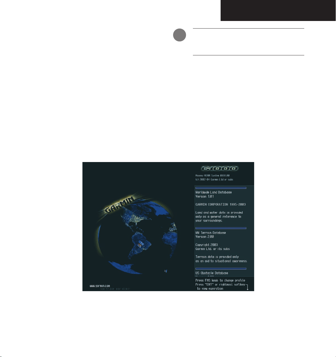
Figure 8.1.1 MFD Start-Up Page
Garmin G1000 MFD Pilot’s Guide for the Mooney M20M & M20R190-00448-00 Rev. A
8-1
Page 4

INTRODUCTION
POWER-UP PAGE
The Power-up Page displays general information such
as software version and database versions to the pilot
upon power-up of the G1000 system. The Power-up Page
displays the following data, shown in a scrolling list:
• Product name.
• System software version number.
• Copyright string.
• Company name.
• Company web page.
• Company latitude and longitude location.
• Checklist filename and copyright information or
text indicating that no checklist file is present.
• Land database name, version, copyright information, and warning information if land database is
present; otherwise, if no land database is present,
text indicating that no land database is present.
• Terrain database name, version, copyright information, and warning information if terrain database
is present; otherwise, if no terrain database is
present, text indicating that no terrain database is
present.
• Aviation database name, version, effective dates,
and copyright information if aviation database
is present; otherwise, if no aviation database is
present, text indicating that no aviation database
is present.
• If the aviation database is out of date, then the pilot
shall be forced to view text that states the aviation
database is out of date.
• If the airframe allows pilot created pilot profiles
then the active profile is displayed.
• Obstacle database name, version, copyright
information, and warning information if obstacle
database is present; otherwise, if no obstacle database is present, text indicating that no obstacle
database is present.
OPERATIONS
The pilot can change the active profile (see System
Setup Section).
BACKLIGHTING
See the Primary Flight Display Pilot’s Guide for instruc-
tions on adjusting backlighting.
To acknowledge the Power up Page information and
proceed to the Navigation Map Page press the
twice.
ENT key
8-2
Garmin G1000 MFD Pilot’s Guide for the Mooney M20M & M20R 190-00448-00 Rev. A
Page 5

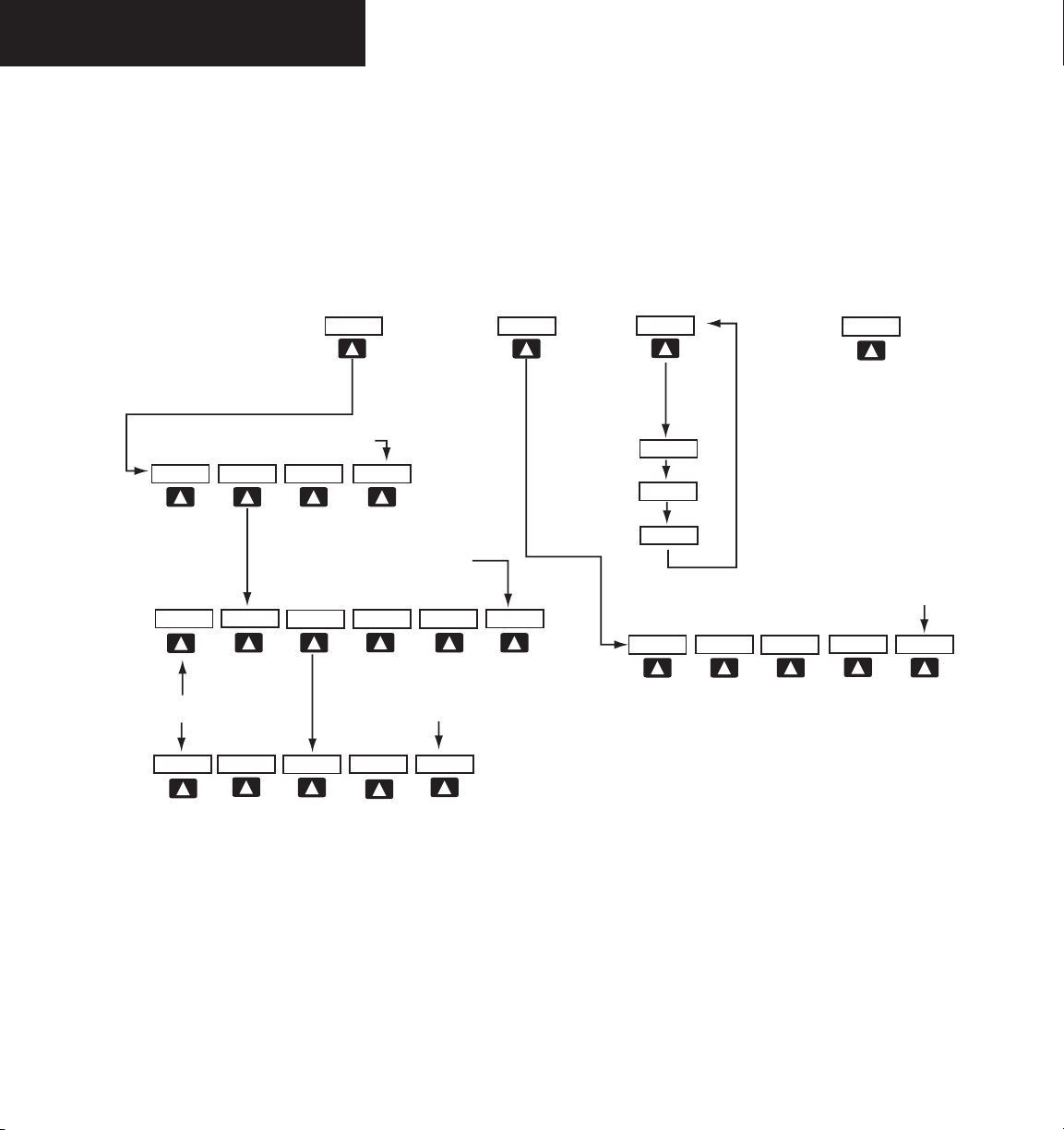
MFD SOFTKEYS
The MFD softkeys are located below the display glass
and provide control over flight management functions
which includes GPS and NAV management, engine and
airframe monitoring, terrain, weather, and traffic. Figure
8.1.2 shows an MFD flowchart identifying what functions
are available via the softkey labels.
The MFD softkeys perform the following functions:
ENGINE – Pressing the ENGINE softkey makes
available the LEAN and SYSTEM softkeys which
in turn access the Lean Page and the System Page,
respectively.
MAP – pressing the MAP softkey enables the follow-
ing softkeys:
TRAFFIC – pressing the TRAFFIC softkey
displays/removes Traffic on the Navigation
Map.
TOPO – pressing the TOPO softkey displays
or removes topographic information on the
Navigation Map.
TERRAIN – pressing the TERRAIN softkey
displays/removes terrain and obstacle data
on the Navigation Map.
LTNG – Press to display lightning data on the
Navigation Map Page (within a 200 nm
radius of the aircraft).
BACK – pressing the BACK softkey displays
the ENGINE and MAP top level softkeys.
DCLTR (declutter) – pressing the DCLTR softkey
removes map information in three levels.
INTRODUCTION
Garmin G1000 MFD Pilot’s Guide for the Mooney M20M & M20R190-00448-00 Rev. A
8-3
Page 6
INTRODUCTION
BACK
RST USED
SYSTEM
ENGINE
LEAN
ENGINE
MAP
DCLTR
BACK
SYSTEM
LEAN
ENGINE
ENGINE
LEAN
BACK
SYSTEM
Press the ENGINE softkey on any level to
return to the LEAN and SYSTEM softkey level
TRAFFIC
TOPO
BACK
TERRAIN
DCLTR-2
DCLTR-3
DCLTR-1
Press the BACK softkey on this level to
return to the top softkey level
Press the BACK softkey on this level to
return to the top softkey level
Press the BACK softkey on this level to
return to the top softkey level
Press the BACK softkey on this level to
return to the top softkey level
CHKLIST
ASSIST
CYL SLCT
LTNG
NOTE:Nav III does not use the checklist
functionality which exists in the G1000
8-4
Garmin G1000 MFD Pilot’s Guide for the Mooney M20M & M20R 190-00448-00 Rev. A
Figure 8.1.2 MFD Softkeys
Page 7

INTRODUCTION
MFD PAGE GROUPS
The MFD displays GPS/Navigation flight information
in the following page groups:
• Map (MAP):
Navigation Map Page
Traffic Map Page
Weather Map Page
Terrain Proximity Page
• Waypoint (WPT) :
Airport Information Page
Intersection Information Page
NDB Information Page
VOR Information Page
User Waypoint Information Page
• Auxiliary (AUX):
Trip Planning Page
Utility Page
GPS Status Page
System Setup Page
System Status Page
• Nearest (NRST):
Nearest Airports Page
Nearest Intersections Page
Nearest NDB Page
Nearest VOR Page
Nearest User Waypoints Page
Nearest Frequencies Page
Neatest Airspaces Page
To select a specific page group:
1. Turn the
large FMS
knob until the desired page
group is selected.
Active Page group is
highlighted
Figure 8.1.3 Page Group Window
Currently
selected page is
highlighted
To select a different page within the group:
1. Turn the
small FMS
knob. As the knob is turned,
the bottom right corner of each page indicates
the page group that is currently being displayed
(e.g., MAP or NRST, etc.), the number of screens
available within that group (indicated by rectangle icons) and the placement of the current
page within that group (indicated by a solid
cyan rectangle icon). The page group and active
page title window are displayed above the nav
map display.
Page Group
Figure 8.1.4 Page Title Window
Active Page Title
Garmin G1000 MFD Pilot’s Guide for the Mooney M20M & M20R190-00448-00 Rev. A
8-5
Page 8
INTRODUCTION
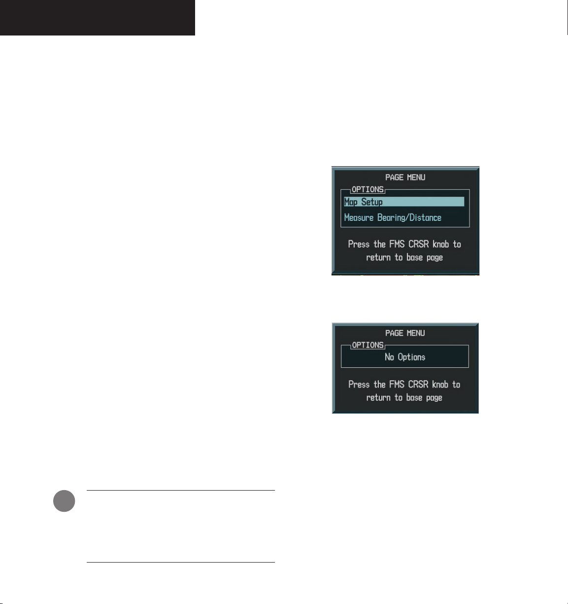
Working With Menus
Much of the operation of the G1000 is accomplished
using a menu interface. The G1000 has a bezel-mounted
dedicated menu key that when pressed, displays a context-sensitive list of options. This options list allows the
pilot to access additional features or make settings changes
which specifically relate to the currently displayed page.
Some menus provide access to additional submenus that
are used to view, edit, select, and, review options. Some
menus display ‘NO OPTIONS’ when there are no options
for the page selected.
The main keys which are used in association with all
page group operations are listed below:
• CLR – erases information or cancels an entry.
Press and hold
Navigation Map Page, regardless of the page currently displayed.
• ENT – accepts a menu selection or data entry.
Approves an operation or completes data entry.
Also, confirms information.
• BACK – resets the MFD softkeys to their default
settings (ENGINE, MAP, DCLTR, MODE, VIEW,
etc).
• DCLTR – removes information from the moving
map in a progressive manner with each key-press.
• MENU – displays a context-sensitive list of
options that allows access to additional features or
that allows the pilot to change the settings which
relate to the currently displayed page.
CLR to immediately display the
There may be more options than can be displayed so
you may have to turn the small or large FMS knob to
scroll through the list to identify them. In all cases, once
the menu is displayed the small or large FMS knob is
turned to highlight an item and the ENT key is pressed
to select that item or the CLR key removes the menu and
cancels the operation. Pressing the softkeys does not
display a menu or submenu.
Figure 8.1.5 Menu With Options
Figure 8.1.6 Menu With No Options
8-6
NOTE: Data is entered using the large and small
FMS knob. Practice with them to become efficient at entering data. This will greatly reduce
the amount time spent operating the MFD in
flight.
Garmin G1000 MFD Pilot’s Guide for the Mooney M20M & M20R 190-00448-00 Rev. A
Page 9
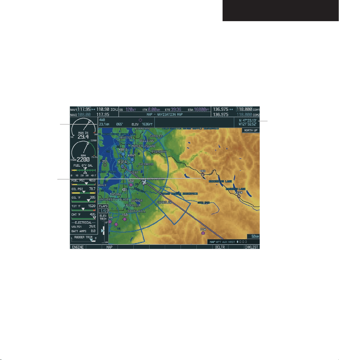
NAVIGATION MAP PAGE
8.2 NAVIGATION MAP PAGE
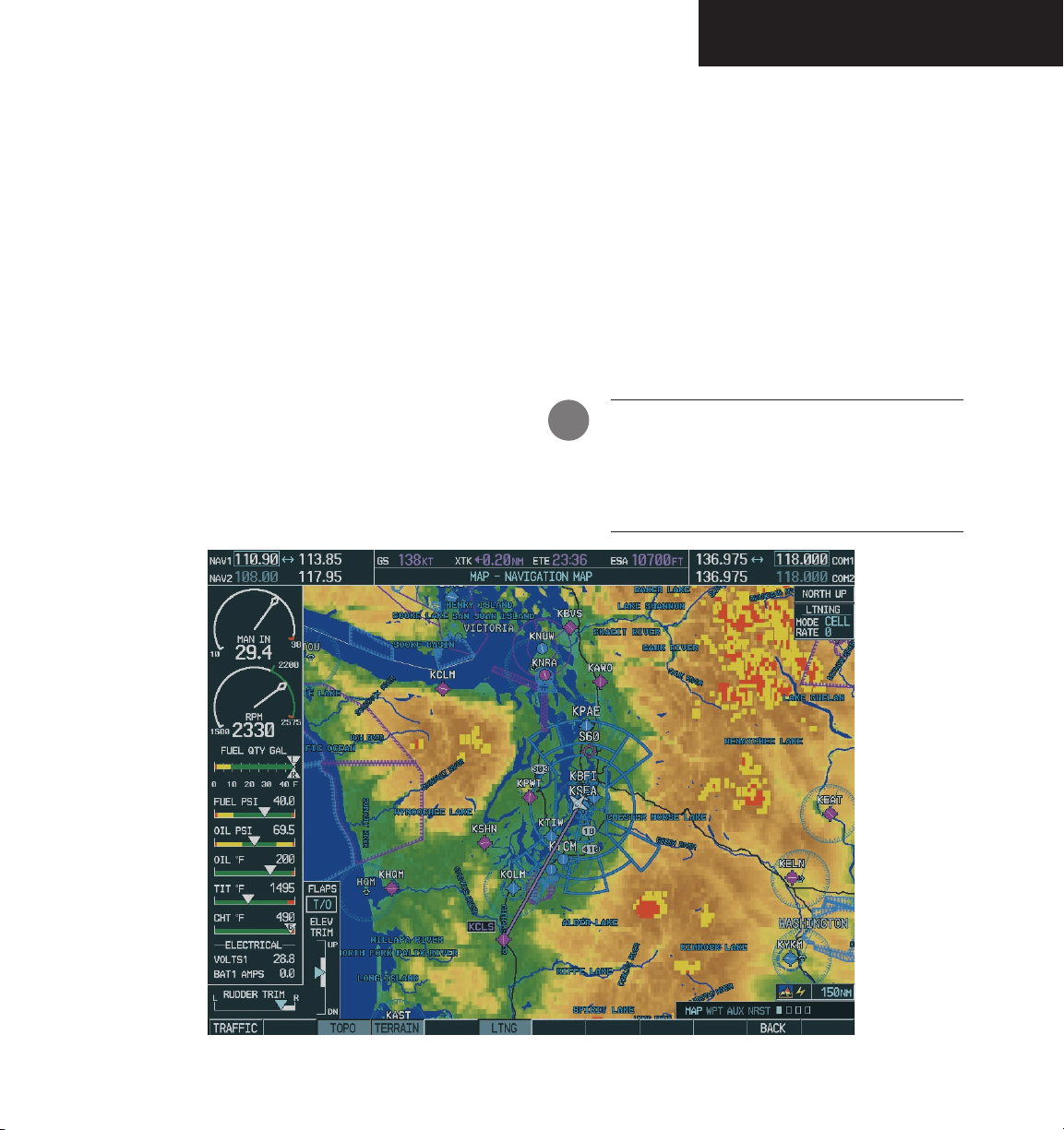
The Navigation Map Page provides an extensive array of GPS/navigation/mapping capability.
Key features include:
• Map display showing airports, navaids, airspaces,
land data (highways, cities, lakes, rivers, borders,
etc.) with names (labels)
• Map pointer information (distance and bearing
to pointer, location of pointer, name and other
pertinent information)
• TIS Traffic Display
• Lightning Display
• Obstacle Display
• Map Zoom Range Legend
• Wind Direction and Speed
• Heading Indication
• Aircraft icon representing present position
• Icons for enabled map features
• Track Vector
• Topography Scale
• Fuel Range Ring
• Topography Data
• Terrain Proximity Data
Appendix F lists all of the display features provided by
the Navigation Map Page.
WARNING: The Navigation Map page display
should be used only for non-navigational situational awareness and not for navigation. Any
map display indication should be compared with
approved navigation sources.
Figure 8.2.1 Navigation Map Page
Garmin G1000 MFD Pilot’s Guide for the Mooney M20M & M20R190-00448-00 Rev. A
8-7
Page 10

NAVIGATION MAP PAGE
To select the Navigation Map Page:
1. Turn the
group.
2. Turn the
Navigation Map Page. The page group name
and page title is displayed below the navigation status bar; ‘MAP – NAVIGATION MAP’.
In addition to turning the
knobs, the Navigation Map Page can be selected
from any page by pressing and holding the
(DFLT MAP) key
large FMS
small FMS
.
knob to select the Map Page
knob to select the
large and small FMS
CLR
8-8
Garmin G1000 MFD Pilot’s Guide for the Mooney M20M & M20R 190-00448-00 Rev. A
Page 11
NAVIGATION MAP PAGE
NAVIGATION MAP PAGE OPERATIONS
The following Navigation Map Page operations can be
performed:
• Changing the Map Orientation
• Clearing Lightning Data
• Selecting a Map Range
• Using the Auto Zoom Feature
• Identifying Aviation Map Data
• Decluttering the Map
• Panning the Map
• Displaying Topographic Information on the
Navigation Map Page
• Displaying Terrain Information on the Navigation
Map Page
• Displaying Traffic on the Navigation Map Page
• Displaying Lighting Data on the Navigation Map
Page
• Displaying Obstacles
• MFD Navigation Status Window
• Navigation Map Page Options Menu
Changing the Map Orientation
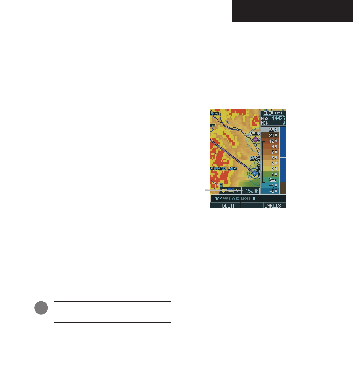
Selecting a Map Range
The Navigation Map Page can be set to 28 different
range settings from 500 feet to 2000 nautical miles. The
current range is indicated in the lower right corner of the
Navigation Map Page and represents the top-to-bottom
distance covered by the map. To change the map range
turn the joystick counter-clockwise to zoom in, turn it
clockwise to zoom out.
Map Range
Figure 8.2.2 Navigation Map Range
See the Navigation Map Page Menu section for instruc-
tions on how to change the map orientation.
Clearing Lightning Data
See the Navigation Map Page Menu section for instructions on how to clear lightning data from the map
display
NOTE: A complete list of available map datums
are given in Appendix D.
Garmin G1000 MFD Pilot’s Guide for the Mooney M20M & M20R190-00448-00 Rev. A
Using the Auto Zoom Feature
The auto zoom feature automatically adjusts the
map from an enroute range of 2000 nm through
each lower range, stopping at a range of 1.5 nm as
the aircraft approaches the destination waypoint.
See the Navigation Map Page Menu section for instructions on enabling/disabling the auto zoom
feature.
8-9
Page 12

NAVIGATION MAP PAGE
Identifying Aviation Map Data
The following aviation data is displayed on the
Navigation Map Page:
Airport Symbols:
• Non-towered airports (purple in color).
• Towered airports (blue in color).
• Non-serviced airports (displayed as solid circle
icons). See Appendix F for symbology definitions.
• Serviced airports (displayed as circles with protruding tick marks pointing to the top, bottom,
left, and right portions of the screen).
Classification
• Unclassified airports (displayed with a question
mark “?” character centered within the airport
symbol).
• Restricted airports (displayed with the letter “R”
centered within the airport symbol).
• Hard surface public airports (displayed with the
airports longest runway oriented according to
the direction in which it runs centered within the
airport symbol).
• Heliports (displayed with the letter “H” centered
within the heliport symbol).
• Soft surface public airports (displayed with ahollow circle in the center of the airport symbol).
Airspace:
The Navigation Map Page displays airspace as one of
the following colors:
• Blue:
ICAO control area
Class B, Alert area
Caution area, Danger area, Prohibited area
Restricted area, Training area
Unknown area, Warning area
Terminal Zone Airspace (ATZ), Class D
:
• Purple:
Class C
ICAO terminal control area
Terminal radar service area (TRSA)
Mode C area
Military operations area (MOA)
Mode C
Class A
Class E
Line Style:
The Navigation Map Page displays airspace as one of
the following line styles:
• Solid line:
Class C
ICAO control area
ICAO terminal control area
Class B, Terminal radar service area
Mode C, Class A
• Dashed line:
Mode C tower area
Class D, Class E
• Consecutive parallel lines forming a
boundary defining the airspace:
Military operations area (MOA)
Warning area, Alert area, Caution area
Danger area, Prohibited area
Restricted area, Training area
Unknown area, Terminal Zone Airspace (ATZ)
NOTE: See Appendix F for a complete description of the aviation map symbology used on the
Navigation Map Page.
8-10
Garmin G1000 MFD Pilot’s Guide for the Mooney M20M & M20R 190-00448-00 Rev. A
Page 13

Decluttering the Map
The Navigation Map Page can be quickly decluttered
by repeatedly pressing the DCLTR softkey until the desired
detail is depicted. The declutter level label appears above
the DCLTR softkey. Table 8.2.1 lists the map features that
are turned off at each declutter level.
NAVIGATION MAP PAGE
Map Features always
Flight plan route waypoints Land/Country Text
NOTE: Some of the map features are automatically removed at certain zoom ranges due to the
map setup configuration for each map item.
NOTE: “SUA” listed in the table below stands
for Special Use Airspace. These are controlled
airspaces, military zones, etc.
No Declutter Declutter ( –1) Declutter (-2) Declutter (-3)
displayed
Flight plan route lines All Map features
are visible
Rivers/Lakes
Topography data
Terrain Proximity data
Map Borders ----------- SUA Group 0 Runway Labels
Bearing Line Freeways SUA Group 1
Lightning Strike data National Highways SUA Group 2
Nexrad data Local Highways SUA Group 5
Traffic Symbols
Traffic Labels
River/Lakes Names Only User waypoints Large Airports
Latitude/Longitude Grid Medium Airports
Large City VORs Small Airports
Medium City NDBs SUA Group 3
Small City Intersections SUA Group 4
Local Roads SUA Group 6
Local Road Labels SUA Group 7
Railroads
Major Political Boundaries
Obstacles
Table 8.2.1 Map Declutter Levels
Garmin G1000 MFD Pilot’s Guide for the Mooney M20M & M20R190-00448-00 Rev. A
8-11
Page 14

NAVIGATION MAP PAGE
Map Panning
Map panning moves the map beyond its current limits
without adjusting the map range. When the panning function is selected by pushing in the joystick, a panning arrow flashes on the map display. A window also appears at
the top of the map display showing the latitude/longitude
position of the pointer, the bearing and distance to the
pointer from the aircraft’s present position, and the elevation of the land at the position of the pointer. When the
panning arrow crosses an airspace boundary, the boundary is highlighted and airspace information is displayed at
the top of the display. The information includes the name
and class of airspace, the ceiling in feet expressed in Mean
Seal Level (MSL), and the floor in feet MSL.
NOTE: The airspace boundary stays highlighted
for approximately four seconds before returning
to normal shading.
To pan the map:
1. Push in the
arrow.
2. Push in and move the
direction of the desired destination to place
the panning arrow at the destination location. When the panning arrow is placed on an
object, the name of the object is highlighted
(even if the name wasn’t originally displayed
on the map). This feature applies to everything
displayed on the map except route lines. When
any map feature or object is selected on the
map display, features or objects are displayed
in the box located at the top of the display.
From here, the pilot can designate the waypoint
as the Direct-to destination. When the
panning arrow crosses an airspace boundary,
the boundary is highlighted and airspace information is displayed at the top of the display.
3. To remove the panning arrow and return to
the present position, push in the
joystick
to display the panning
joystick
in the general
joystick
.
8-12
Garmin G1000 MFD Pilot’s Guide for the Mooney M20M & M20R 190-00448-00 Rev. A
Page 15
NAVIGATION MAP PAGE
Distance, bearing
and elevation
Panning
Arrow
Latitude and longitude
position of pointer
Figure 8.2.3 Navigation Map Panning
Garmin G1000 MFD Pilot’s Guide for the Mooney M20M & M20R190-00448-00 Rev. A
8-13
Page 16
NAVIGATION MAP PAGE
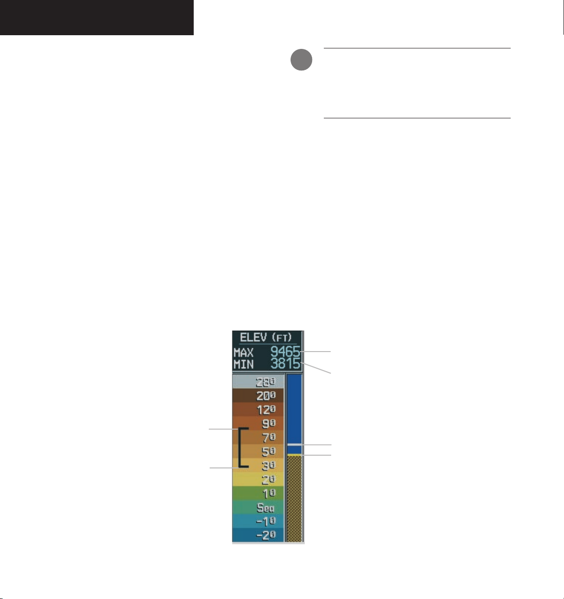
Displaying Topographic Data on the Navigation Map Page
The Navigation Map Page displays various shades of
topography land colors representing the rise and fall of
land elevation similar to aviation sectional charts. The
Navigation Map Page can display a topographic scale
representing various key points of terrain elevation colors
with their associated elevation value labeled.
To display topographic data on the Navigation Map Page:
MAP
1. Press the
2. Press the
be displayed on the Navigation Map Page by
using the ‘On/Off’ topo data map setup feature.
See the Navigation Map Page setup menu section.
softkey.
TOPO
softkey. Topo data can also
NOTE: Press the
topo data from the Navigation Map Page.
When topo data is removed from the page,
the Jeppesen Nav data is presented on a black
background.
TOPO
softkey again to remove
8-14
Onscreen map maximum
elevation
Onscreen map minimum
elevation
Maximum
Aircraft altitude
Ground elevation
Minimum
Figure 8.2.4 Topography Scale
Garmin G1000 MFD Pilot’s Guide for the Mooney M20M & M20R 190-00448-00 Rev. A
Page 17
NAVIGATION MAP PAGE
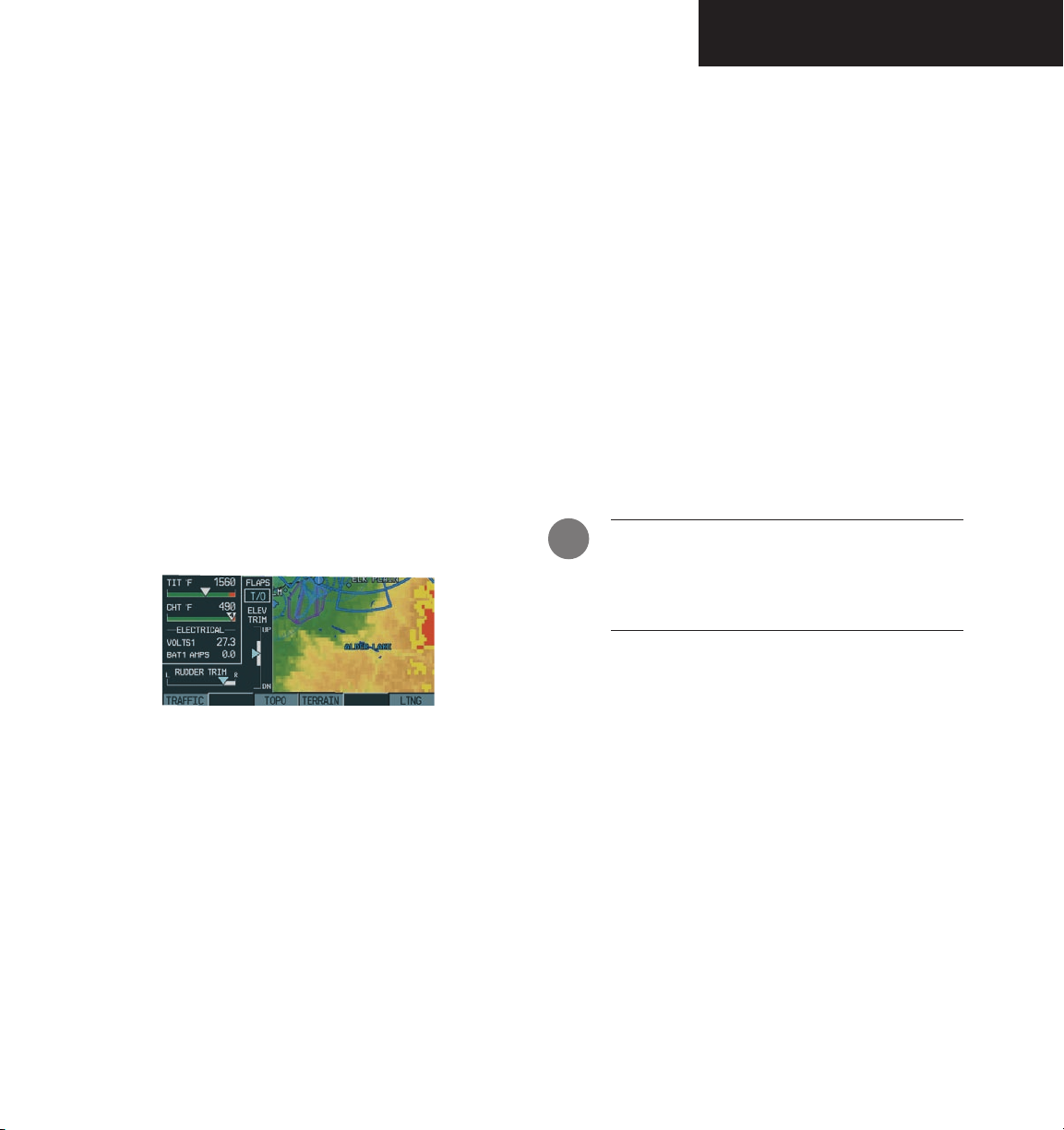
Displaying Terrain Data on the Navigation Map Page
Terrain data can be displayed on the Naviga-
tion Map Page by pressing the TERRAIN softkey. Terrain symbology (mountain icons) appear next to the
map range in the bottom right corner of the page indicating the presence of terrain data on the map. See
the Terrain Proximity Page section for a terrain color
interpretation chart.
To display terrain data on the Navigation
Map Page:
MAP
1. Press the
2. Press the
softkey again to remove terrain data from the
Navigation Map Page.
softkey.
TERRAIN
softkey. Press the
TERRAIN
generate traffic notification. Surveillance data includes
all transponder-equipped aircraft within the coverage
volume. The G1000 displays up to eight traffic targets
within a 7.5 nautical mile radius, from 3,000 feet below to
3,500 feet above the requesting aircraft. See Appendix E
for a full description of TIS. A traffic symbol appears next
to the map range in the bottom right corner of the display
indicating the presence of traffic data on the map.
The TIS ground sensor uses real time track reports to
To display traffic on the Navigation Map
Page:
MAP
1. Press the
2. Press the
TRAFFIC
Navigation Map Page.
NOTE: Traffic and terrain data can also be
displayed by using the ‘On/Off’ Navigation Map
Page option. See the Navigation Map Page setup
section for details.
softkey.
TRAFFIC
softkey again to remove traffic from the
softkey. Press the
Figure 8.2.5 TRAFFIC, TOPO TERRAIN, and LTNG Softkeys
Displaying Traffic on the Navigation Map Page
Pressing the TRAFFIC softkey displays Traffic Informa-
tion Service (TIS) traffic on the Navigation Map Page. TIS
is a ground-based service providing relative location of all
ATCRBS Mode-A and Mode-C transponder equipped aircraft within a specified service volume.
Garmin G1000 MFD Pilot’s Guide for the Mooney M20M & M20R190-00448-00 Rev. A
8-15
Page 18

NAVIGATION MAP PAGE
Displaying Lightning Data on the Navigation Map Page
Pressing the LTNG softkey after pressing the MAP
softkey displays WX-500 Stormscope data on the Navigation Map Page within a maximum of 200 nm radius of the
aircraft.
The Navigation Map Page displays cell or strike
information using yellow lightning strike symbology.
This added capability improves situational awareness,
which makes it much easier for the pilot to relate storm
activity to airports, navaids, obstacles and other ground
references.
To display lightning data on the Navigation
Map Page:
MAP
1. Press the
2. Press the
softkey again to remove lightning data from
the Navigation Map Page
softkey.
LTNG
softkey. Press the
LTNG
In normal operation, the current mode and rate
are displayed in the top right corner of the Navigation
Map Page. The mode is described by the word ‘STRIKE’
when in strike mode, or ‘CELL’ when in cell mode.
The strike data display phases are:
1. Lightning Symbol (latest strikes; less than one
minute; a black guard band is placed around
the strike symbol during the first six seconds of
display)
Lightning Data Display Range
Lightning data can be displayed up to 800 nm
zoom range, but the data only goes out as far as the
Stormscope can report (200 nm). The 500 nm zoom
range will display all lightning data. Ranges greater
than 500 nm do not display any further Stormscope
data.
MFD Navigation Status Window
The MFD Navigation Status Window displays four,
user-configurable fields which can show the following
data:
• Bearing to next waypoint (BRG)
• Distance to next waypoint (DIS)
• Desired track to next waypoint (DTK)
• En-route safe altitude (ESA)
• Estimated Time of Arrival (ETA)
• Estimated Time Enroute (ETE)
• Ground Speed (GS)
• Maximum Safe Altitude (MSA)
• Track angle error (TKE)
• Track angle (TRK)
• Vertical speed required (VSR)
• Cross track error (XTK)
• Currently selected MFD page title
8-16
2. Large Plus ‘+’ sign (more than one minute old)
3. Small Plus ‘+’ sign (more than two minutes old)
4. Strike Data is no longer displayed (after three
minutes)
Garmin G1000 MFD Pilot’s Guide for the Mooney M20M & M20R 190-00448-00 Rev. A
Figure 8.2.6 MFD Navigation Status Window
NOTE: Instructions on changing a data field on
the MFD Navigation Status Window is given in
the System Setup Section.
Page 19
NAVIGATION MAP PAGE
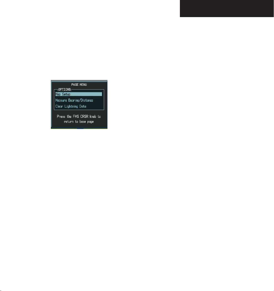
Navigation Map Page Menu
The Navigation Map Page can be customized using
three page menu options: ‘Map Setup’, ‘Measure
Bearing/Distance’, and ‘Clear Lightning Data’. To display
the page menu, press the MENU key (with the Navigation
Map Page displayed).
Figure 8.2.7 Navigation Map Page Menu Options
First Option: ‘MAP SETUP’
The first option is ‘MAP SETUP’. There are five
“groups” available under the ‘MAP SETUP’ option: Map,
Weather, Traffic, Aviation, and Land (Figure 8.2.8). The
Map Group will be discussed first followed by the remaining four.
Map Group
There are eleven options in the Map Group. The first
is ‘ORIENTATION’.
Orientation
There are four map orientation selections: ‘North up’,
‘Track up’, ‘DTK up’, and ‘HDG up’.
• North up fixes the top of the map to a north head
-
ing (default map setting).
• Track up adjusts the top of the map display to the
current track heading.
• Desired Track Up (DTK up) fixes the top of the
map display to the desired course.
• Heading Up (HDG up) fixes the top of the map
display to the current aircraft heading.
To change the map orientation:
1. With the Navigation Map Page displayed,
MENU
press the
key to display the Navigation
Map Page Menu. The cursor flashes on ‘Map
Setup’.
ENT
2. Press the
key. The Map Setup Menu is
displayed.
3. Turn the
group and press the
4. Turn the
small FMS
large FMS
knob to select the ‘
ENT
key.
Map’
knob to highlight the
‘ORIENTATION’ field.
5. Turn the
small FMS
orientation and press the
6. Press the
FMS
knob to select the desired
ENT
key.
knob to return to the Navigation
Map Page.
Garmin G1000 MFD Pilot’s Guide for the Mooney M20M & M20R190-00448-00 Rev. A
8-17
Page 20

NAVIGATION MAP PAGE
Auto Zoom
The automatic zoom feature automatically adjusts the
map range from 2000 nm through each lower range, stop
ping at 1.5 nm as the aircraft approaches the destination
waypoint.
To enable/disable automatic zoom:
1. With the Navigation Map Page displayed, press
the
MENU
key to display the Navigation Map
Page Menu. The cursor flashes on the ‘Map
Setup’ option.
ENT
2. Press the
key. The Map Setup Menu is
displayed.
3. Turn the
group and press the
4. Turn the
small FMS
large FMS
knob to select the ‘
ENT
key.
Map’
knob to highlight the ‘AUTO
ZOOM’ field.
5. Turn the
and press the
6. Press the
small FMS
FMS
knob to select ‘On’ or ‘Off’
ENT
key.
knob to return to the Navigation
Map Page.
Land Data
The Navigation Map Page can display background
land data (roads, lakes, borders, etc). The background
land data can also be turned off.
To enable/disable land data:
1. With the Navigation Map Page displayed, press
the
MENU
key to display the Navigation Map
Page Menu. The cursor flashes on the ‘Map
Setup’ option.
ENT
2. Press the
key. The Map Setup Menu is
displayed.
3. Turn the
group and press the
4. Turn the
small FMS
large FMS
knob to select the ‘
ENT
key.
Map’
knob to highlight the ‘LAND
DATA’ field.
5. Turn the
Press the
6. Press the
small FMS
ENT
FMS
knob to select ‘On’ or ‘Off.’
key.
knob to return to the Navigation
Map Page.
8-18
Garmin G1000 MFD Pilot’s Guide for the Mooney M20M & M20R 190-00448-00 Rev. A
Page 21

NAVIGATION MAP PAGE
Track Vector
The Navigation Map Page can display a track vector
using a dashed cyan line segment with an arrowhead
attached to the end, extended to a predicted location in
60 seconds along the current aircraft track. The track vector is useful in minimizing track angle error.
To enable/disable the track vector:
1. With the Navigation Map Page displayed, press
the
MENU
key to display the Navigation Map
Page Menu. The cursor flashes on the ‘Map
Setup’ option.
ENT
2. Press the
key. The Map Setup Menu is
displayed.
3. Turn the
group and press the
4. Turn the
small FMS
large FMS
knob to select the ‘
ENT
key.
Map’
knob to highlight the
‘TRACK VECTOR’ field.
5. Turn the
‘Off’. Press the
small FMS
knob to select ‘On’ or
ENT
key to accept the selected
option.
FMS
6. Press the
knob to return to the Navigation
Map Page.
Wind Vector
The wind vector box is displayed in the upper right
corner of the Navigation Map Page and displays wind
direction and speed (in knots). Wind direction is indicated by a 360 degree pointing arrow.
To enable/disable the wind vector box:
1. With the Navigation Map Page displayed, press
the
MENU
key to display the Navigation Map
Page Menu. The cursor flashes on the ‘Map
Setup’ option.
ENT
2. Press the
key. The Map Setup Menu is
displayed.
3. Turn the
group and press the
4. Turn the
small FMS
large FMS
knob to select the ‘
ENT
key.
Map’
knob to highlight the ‘WIND
VECTOR’ field.
5. Turn the
‘Off’. Press the
small FMS
knob to select ‘On’ or
ENT
key to accept the selected
option.
FMS
6. Press the
knob to return to the Navigation
Map Page.
Garmin G1000 MFD Pilot’s Guide for the Mooney M20M & M20R190-00448-00 Rev. A
8-19
Page 22

NAVIGATION MAP PAGE
Nav Range Ring
The Nav range ring shows direction of travel (ground
track) on a rotating compass card. The range of the Nav
compass is determined by the map range, 125 feet (500
feet map range) to 500 nm (2000 nm map range).
To enable/disable the nav range ring:
1. With the Navigation Map Page displayed, press
the
MENU
key to display the Navigation Map
Page Menu. The cursor flashes on the ‘Map
Setup’ option.
ENT
2. Press the
displayed.
3. Turn the
group and press the
4. Turn the
RANGE RING’ field.
5. Turn the
‘Off’. Press the
option.
key. The Map Setup Menu is
small FMS
large FMS
small FMS
knob to select the ‘
ENT
key.
knob to highlight the ‘NAV
knob to select ‘On’ or
ENT
key to accept the selected
Map’
Topo Data
Topographic data can be enabled or disabled on the
Navigation Map Page using the ‘TOPO DATA’ setting. The
topo data range is the maximum map range that topo data
is displayed.
To enable/disable topo data and to select a
topo data range:
1. With the Navigation Map Page displayed, press
the
MENU
key to display the Navigation Map
Page Menu. The cursor flashes on the ‘Map
Setup’ option.
ENT
2. Press the
displayed.
3. Turn the
group and press the
4. Turn the
DATA’ field.
5. Turn the
‘Off’.
key. The Map Setup Menu is
small FMS
large FMS
small FMS
knob to select the ‘
ENT
key.
knob to highlight the ‘TOPO
knob to select ‘On’ or
Map’
8-20
6. Press the
Map Page.
FMS
knob to return to the Navigation
Garmin G1000 MFD Pilot’s Guide for the Mooney M20M & M20R 190-00448-00 Rev. A
ENT
6. Press the
The flashing cursor highlights the range field.
TOPO ranges are from Off to 2000 nm.
7. To change the TOPO range setting, turn the
small FMS
8. Turn the
range and press the
9. Press the
Map Page.
NOTE: When topographic data is removed from
the Navigation Map Page, all cartographic data
is automatically removed and the Jeppesen Nav
data is presented on a black background.
key to accept the selected option.
knob to display the range list.
small FMS
FMS
knob to select the desired
ENT
key.
knob to return to the Navigation
Page 23

NAVIGATION MAP PAGE
Topo Range
The topo range setting enables or disables the
topography scale located in the lower right corner of the
Navigation Map Page.
To enable/disable the topo scale box:
1. With the Navigation Map Page displayed, press
the
MENU
key to display the Navigation Map
Page Menu. The cursor flashes on the ‘Map
Setup’ option.
ENT
2. Press the
key. The Map Setup Menu is
displayed.
3. Turn the
group and press the
4. Turn the
small FMS
large FMS
knob to select the ‘
ENT
key.
Map’
knob to highlight the ‘TOPO
RANGE’ field.
5. Turn the
small FMS
knob to select ‘On’ or
‘Off’.
ENT
6. Press the
key to accept the selected
option.
FMS
7. Press the
knob to return to the Navigation
Map Page.
Terrain Data
Terrain data can be enabled or disabled on the
Navigation Map Page using the ‘TERRAIN DATA’ setting.
A data range can also be selected. The data range is the
maximum map range that terrain data is displayed.
To enable/disable terrain data and to select
a terrain data range:
1. With the Navigation Map Page displayed, press
the
MENU
key to display the Navigation Map
Page Menu. The cursor flashes on the ‘Map
Setup’ option.
ENT
2. Press the
key. The Map Setup Menu is
displayed.
3. Turn the
group and press the
4. Turn the
small FMS
large FMS
knob to select the ‘
ENT
key.
knob to highlight the ‘TER-
RAIN DATA’ field.
5. Turn the
small FMS
knob to select ‘On’ or
‘Off’.
ENT
6. Press the
key to accept the selected option.
The flashing cursor highlights the range field.
TERRAIN ranges are from Off to 2000 nm.
Map’
7. To change the TERRAIN range setting, turn the
small FMS
8. Turn the
range and press the
9. Press the
knob to display the range list.
small FMS
FMS
knob to select the desired
ENT
key.
knob to return to the Navigation
Map Page.
Garmin G1000 MFD Pilot’s Guide for the Mooney M20M & M20R190-00448-00 Rev. A
8-21
Page 24

NAVIGATION MAP PAGE
Obstacle Data
Obstacle data can be enabled or disabled on the
Navigation Map Page using the ‘OBSTACLE DATA’ setting.
A data range can also be selected. The data range is the
maximum map range that terrain data is displayed.
To enable/disable obstacle data and to
select a terrain data range:
1. With the Navigation Map Page displayed, press
the
MENU
key to display the Navigation Map
Page Menu. The cursor flashes on the ‘Map
Setup’ option.
ENT
2. Press the
key. The Map Setup Menu is
displayed.
3. Turn the
group and press the
4. Turn the
small FMS
large FMS
knob to select the ‘
ENT
key.
Map’
knob to highlight the
‘OBSTACLE DATA’ field.
5. Turn the
small FMS
knob to select ‘On’ or
‘Off’.
ENT
6. Press the
key to accept the selected option.
The flashing cursor highlights the range field.
OBSTACLE ranges are from Off to 50 nm.
7. To change the OBSTACLE range setting, turn
the
small FMS
8. Turn the
range and press the
9. Press the
knob to display the range list.
small FMS
FMS
knob to select the desired
ENT
key.
knob to return to the Navigation
Map Page.
Fuel Range Ring (Fuel RNG) (RSV)
The Navigation Map Page can display a fuel range
ring which shows the flight distance that the aircraft has
remaining. A dashed green circle indicates the transition
range to reserve fuel. A solid green circle indicates the
range of all fuel, including the reserve fuel. If only reserve
fuel remains, the range is indicated by a solid yellow
circle.
To enable/disable the fuel range ring and to
select a fuel range time:
1. With the Navigation Map Page displayed, press
the
MENU
key to display the Navigation Map
Page Menu. The cursor flashes on the ‘Map
Setup’ option.
ENT
2. Press the
key. The Map Setup Menu is
displayed.
3. Turn the
group and press the
4. Turn the
small FMS
large FMS
knob to select the ‘
ENT
key.
Map’
knob to highlight the ‘FUEL
RNG (RSV)’ field.
5. Turn the
small FMS
knob to select ‘On’ or
‘Off’.
ENT
6. Press the
key to accept the selected option.
The flashing cursor highlights the fuel reserve
time field. The time indicated is the time the
aircraft can fly with remaining fuel on board.
7. To change the reserve fuel time, turn either
the FMS knob to enter a time (00:00 to 23:
59; hours:minutes). The default setting is 00:
ENT
45 minutes. Press the
key.
8-22
FMS
8. Press the
knob to return to the Navigation
Map Page.
Garmin G1000 MFD Pilot’s Guide for the Mooney M20M & M20R 190-00448-00 Rev. A
Page 25
NAVIGATION MAP PAGE
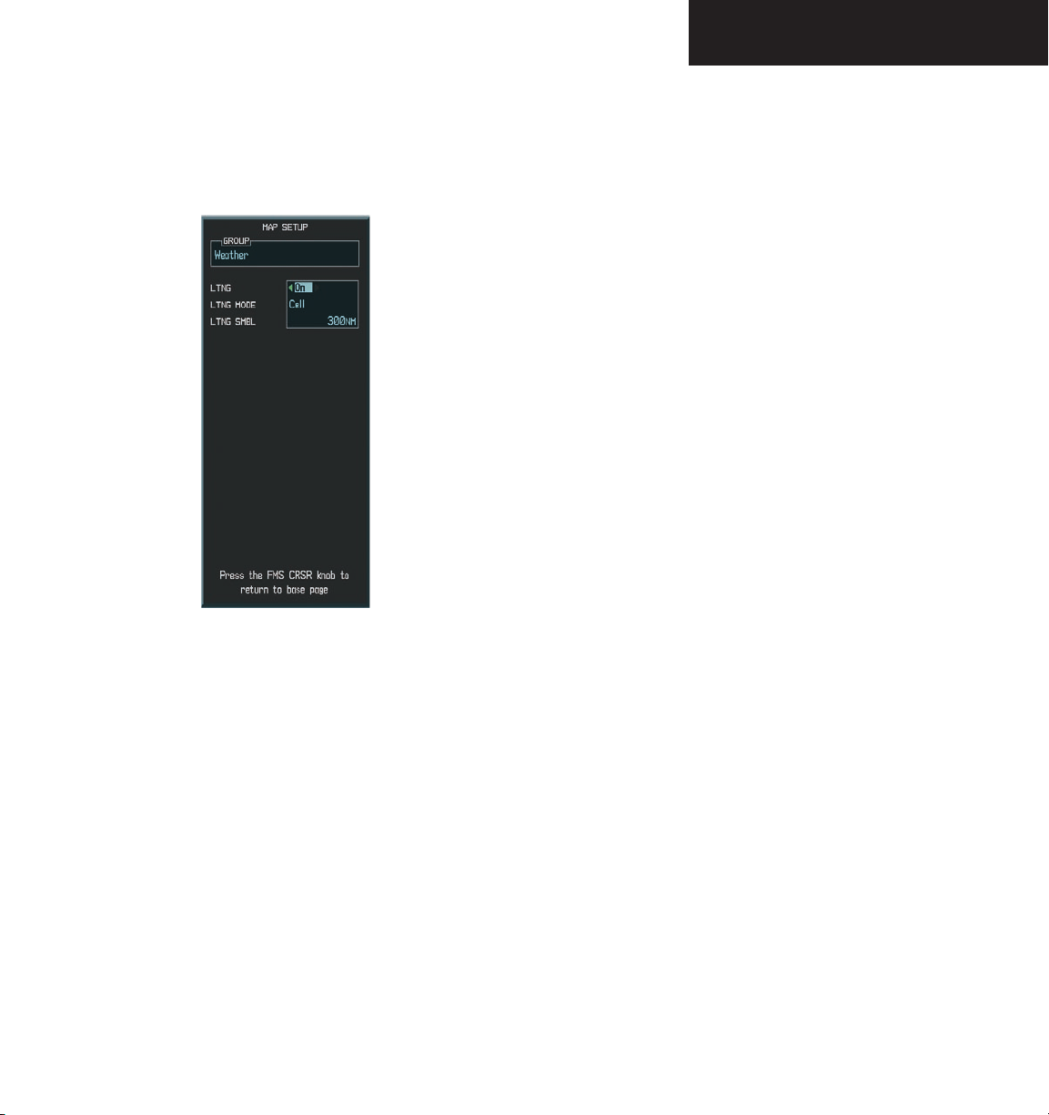
Weather Group
The ‘Weather’ group customizes the display of
lightning on the Navigation Map Page.
Figure 8.2.8 Weather Group
To enable/disable lightning data on the
Navigation Map Page:
1. With the Navigation Map Page displayed, press
the
MENU
key to display the Navigation Map
Page Menu. The cursor flashes on the ‘Map
Setup’ option.
ENT
2. Press the
key. The Map Setup Menu is
displayed.
3. Turn the
group. Press the
small FMS
knob to select the ‘Weather’
ENT
key. The cursor flashes on
‘LTNG’.
4. Turn the small or
large FMS
knob to display
the ‘On/Off’ window.
5. Turn the small FMS knob to select ‘On’
(display lightning) or ‘Off’ (remove lightning).
Press the
6. Press the
ENT
key.
FMS
knob to return to the Navigation
Map Page.
“Cell mode” uses a clustering “program” to identify
clusters of electrical activity that indicate cells. Cell mode
is most useful during periods of heavy storm activity.
Displaying cell data during these periods frees the pilot
from sifting through a screen full of discharge points
and helps to better determine where the storm cells are
located.
Garmin G1000 MFD Pilot’s Guide for the Mooney M20M & M20R190-00448-00 Rev. A
8-23
Page 26

NAVIGATION MAP PAGE
To select ‘cell’ or ‘strike’ as the lightning
mode:
1. With the Navigation Map Page displayed, press
the
MENU
key to display the Navigation Map
Page Menu. The cursor flashes on the ‘Map
Setup’ option.
ENT
2. Press the
key. The Map Setup Menu is
displayed
3. Turn the
group. Press the
small FMS
knob to select the ‘Weather’
ENT
key. The cursor flashes on
‘LTNG’.
4. Turn the
large FMS
knob to select ‘LTNG
MODE’.
5. Turn either the small or
large FMS
knob to
display the ‘Cell/Strike’ window.
6. Turn the
‘Strike’. Press the
7. Push the
small FMS
FMS
knob to select ‘Cell’ or
ENT
key.
knob to return to the Navigation
Map Page.
To select a lightning symbol zoom range:
1. With the Navigation Map Page displayed, press
the
MENU
key to display the Navigation Map
Page Menu. The cursor flashes on the ‘Map
Setup’ option.
ENT
2. Press the
key. The Map Setup Menu is
displayed.
3. Turn the
group. Press the
small FMS
knob to select the ‘Weather’
ENT
key. The cursor flashes on
‘LTNG’.
4. Turn the
large FMS
knob to select ‘LTNG
SMBL’.
5. Turn either the
small or large FMS
knob to
display the range window.
6. Turn the
range. Press the
7. Push the
small FMS
FMS
knob to select the desired
ENT
key.
knob to return to the Navigation
Map Page.
Lightning data can be displayed up to 800 nm zoom
range (north up). In the ‘track up’ mode there is a
portion of lightning that could be behind the aircraft
that cannot be seen at this range. Since the range of the
Stormscope is 200 nm (in front) in addition to another
200 nm (behind) (400 nm diameter total), the 500 nm
range (in north up mode) shows all the data.
8-24
Garmin G1000 MFD Pilot’s Guide for the Mooney M20M & M20R 190-00448-00 Rev. A
Page 27
NAVIGATION MAP PAGE
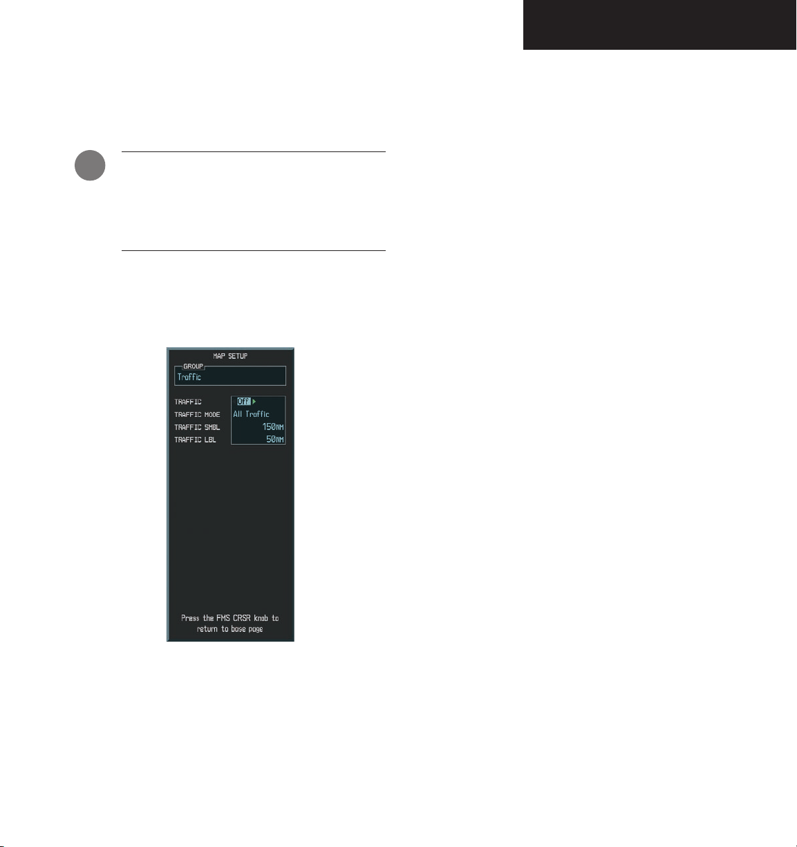
Traffic Group
The Traffic group customizes the display of traffic on
the Navigation Map Page.
Traffic is only displayed on the Navigation
Map Page if aircraft heading data is available.
If heading is not available, traffic advisories
are displayed as non-bearing banners on the
Navigation Map Page.
To enable/disable traffic data on the Navigation Map Page:
1. With the Navigation Map Page displayed, press
the
MENU
key to display the Navigation Map
Page Menu. The cursor flashes on the ‘Map
Setup’ option.
ENT
2. Press the
displayed
3. Turn the
group. Press the
on the ‘TRAFFIC’ field.
4. Turn the
‘Off’.
5. Press the
option.
6. Press the
Map Page.
key. The Map Setup Menu is
small FMS
small FMS
ENT
FMS
knob to select the ‘Traffic’
ENT
key. The cursor flashes
knob to select ‘On’ or
key to accept the selected
knob to return to the Navigation
Figure 8.2.9 Traffic Group Options
Garmin G1000 MFD Pilot’s Guide for the Mooney M20M & M20R190-00448-00 Rev. A
8-25
Page 28

NAVIGATION MAP PAGE
To select a traffic mode:
1. With the Navigation Map Page displayed, press
the
MENU
key to display the Navigation Map
Page Menu. The cursor flashes on the ‘Map
Setup’ option.
ENT
2. Press the
key. The Map Setup Menu is
displayed.
3. Turn the
group. Press the
small FMS
knob to select the ‘Traffic’
ENT
key. The cursor flashes
on the ‘TRAFFIC’ field.
4. Turn the
large FMS
knob to highlight the
‘TRAFFIC MODE’ field.
5. Turn the
small FMS
knob to select the desired
option.
ENT
6. Press the
key to accept the selected
option.
FMS
7. Press the
knob to return to the Navigation
Map Page.
To select a traffic symbol zoom range:
1. With the Navigation Map Page displayed, press
the
MENU
key to display the Navigation Map
Page Menu. The cursor flashes on the ‘Map
Setup’ option.
ENT
2. Press the
key. The Map Setup Menu is
displayed
3. Turn the
group. Press the
small FMS
knob to select the ‘Traffic’
ENT
key. The cursor flashes
on the ‘TRAFFIC’ field.
4. Turn the
large FMS
knob to highlight the
‘TRAFFIC SMBL’ field. Traffic symbol zoom
ranges are from Off to 300 nm.
5. Turn the
small FMS
knob to select the desired
option.
ENT
6. Press the
key to accept the selected
option.
7. Press the
FMS knob
to return to the Navigation
Map Page.
8-26
The ‘TRAFFIC MODE’ mode selects which traffic is displayed (all traffic, traffic and proximity advisories, or traffic
advisories only). The traffic symbol is the symbol used to
depict the type of traffic:
• Traffic Advisories (TA) – Yellow
• Proximity Advisories (PA) – White
• Other – White
Proximity Advisories (PAs) are displayed as solid white
diamonds. PAs are defined as traffic within the 4.0
nm range, within ± 1200 ft. of altitude separation,
and are not traffic advisories (TAs).
Garmin G1000 MFD Pilot’s Guide for the Mooney M20M & M20R 190-00448-00 Rev. A
Page 29

The traffic label displays the altitude separation above
or below the symbol and the vertical speed sense arrow to
the right of the symbol.
To select a traffic label zoom range:
1. With the Navigation Map Page displayed, press
the
MENU
key to display the Navigation Map
Page Menu. The cursor flashes on the ‘Map
Setup’ option.
ENT
2. Press the
key. The Map Setup Menu is
displayed
NAVIGATION MAP PAGE
3. Turn the
group. Press the
small FMS
knob to select the ‘Traffic’
ENT
key. The cursor flashes
on the ‘TRAFFIC’ field.
4. Turn the
large FMS
knob to highlight the
‘TRAFFIC LBL’ field. Traffic label zoom ranges
are from Off to 300 nm.
5. Turn the
small FMS
knob to select the desired
option.
ENT
6. Press the
key to accept the selected
option.
FMS
7. Press the
knob to return to the Navigation
Map Page.
Garmin G1000 MFD Pilot’s Guide for the Mooney M20M & M20R190-00448-00 Rev. A
8-27
Page 30
NAVIGATION MAP PAGE
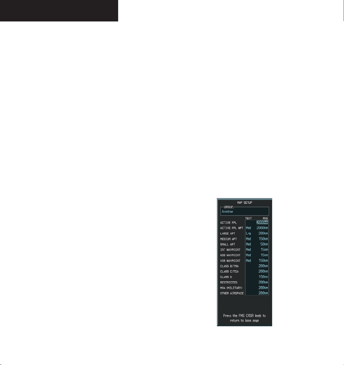
Aviation Group Options
The Aviation group customizes the display of aviation
symbology on the Navigation Map Page.
• Active Flight Plan (ACTIVE FPL)- the active flight
plan zoom range sets the maximum range at which the
active flight plan magenta line is displayed on the display
(off - 2000 nm).
• Active Flight Plan Waypoint (ACTIVE FPL WPT)the active flight plan waypoint label size sets the size at
which the active flight plan names appear on the display
(none, small, medium, and large). The zoom range sets
the maximum range at which active flight plan waypoints
appear on the display (off - 2000 nm).
• Large, Medium, and Small Airports (LARGE APT,
MEDIUM APT, SMALL APT) - The airport label size sets
the size at which the large, medium, or small airport
names size appear on the display. The zoom range sets
the maximum range at which the airports appear on the
display:
• Airspace Boundaries (CLASS B/TMA, CLASS C/TCA,
and CLASS D) - The airspace zoom range sets the maximum range at which the three classes of airspace appear
on the display. The zoom range sets the maximum range
at which the airspace boundaries appear on the display:
• CLASS B: off - 500 nm
• CLASS C: off - 500 nm
• CLASS D: off - 300 nm
• “Other” Airspace Boundaries (RESTRICTED, MOA
(Military), and OTHER AIRSPACE- the other airspace
boundary zoom range sets the maximum range at which
restricted, MOA, and other (training, caution, danger,
warning and alert areas) airspace boundaries are dis
-
played
• RESTRICTED: off - 500 nm
• MOA (MILITARY): off - 500 nm
• OTHER AIRSPACE: off - 500 nm
8-28
• Large: off - 500 nm
• Medium: off - 300 nm
• Small: off - 100 nm
• Intersection, Non-Directional Beacon, and VOR
Waypoints (INT WAYPOINT, NDB WAYPOINT, VOR
WAYPOINT) - The INT, NDB, and VOR label size sets the
maximum range at which the navaids names appear on
the display. The zoom range sets the maximum range at
which the navaids appear on the display:
• INT: off - 30 nm
• NDB: off - 30 nm
• VOR: off - 300 nm
Figure 8.2.10 Aviation Group Options
Garmin G1000 MFD Pilot’s Guide for the Mooney M20M & M20R 190-00448-00 Rev. A
Page 31

NAVIGATION MAP PAGE
To select an aviation group item range:
1. With the Navigation Map Page displayed, press
the
MENU
key to display the Navigation Map
Page Menu. The cursor flashes on the ‘Map
Setup’ option.
ENT
2. Press the
key. The Map Setup Menu is
displayed.
3. Turn the
group. Press the
small FMS
knob to select the ‘Aviation’
ENT
key. The cursor flashes
on the ‘ACTIVE FPL’ field.
4. Turn the
large FMS
knob to select the desired
option.
5. Turn the
small FMS
knob to select the desired
range.
ENT
6. Press the
key to accept the selected
option.
FMS
7. Press the
knob to return to the Navigation
Map Page.
To select an aviation group item text size:
1. With the Navigation Map Page displayed, press
the
MENU
key to display the Navigation Map
Page Menu. The cursor flashes on the ‘Map
Setup’ option.
ENT
2. Press the
key. The Map Setup Menu is
displayed.
3. Turn the
group. Press the
small FMS
knob to select the ‘Aviation’
ENT
key. The cursor flashes
on the ‘ACTIVE FPL’ field.
4. Turn the
large FMS
knob to select the desired
option.
5. Turn the
small FMS
knob to select the desired
text size.
ENT
6. Press the
key to accept the selected text
size.
FMS
7. Press the
knob to return to the Navigation
Map Page.
Garmin G1000 MFD Pilot’s Guide for the Mooney M20M & M20R190-00448-00 Rev. A
8-29
Page 32

NAVIGATION MAP PAGE
Land Group Options
The Land group customizes the display of land data on
the Navigation Map Page.
• Latitude/Longitude (LAT/LON) - the LAT/LON label
size sets the size at which latitude/longitude labels appear
on the display (none, small, medium, and large). The
zoom range sets the maximum range at which LAT/LON
waypoints appear on the display (off - 2000 nm).
• Highways, Roads, and Railroads (FREEWAY,
NATIONAL HIGHWAY, LOCAL HWY, LOCAL ROAD,
RAILROAD) - The highway and road zoom range sets the
maximum range at which highways, roads, and railroads
appear on the display:
• FREEWAY: off - 800 nm
• NATIONAL HWY: off - 80 nm
• LOCAL HWY: off - 30 nm
• LOCAL ROAD: off - 15 nm
• RAILROAD: off - 30 nm
• Cities and Towns (LARGE CITY, MEDIUM CITY,
SMALL CITY) - The cities and town label size sets the
maximum range at which city and town names appear on
the display. The zoom range sets the maximum range at
which cities and towns appear on the display:
• States and Provinces, Rivers and Lakes, and
User Waypoints (STATE/PROV, RIVER/LAKE, USER
WAYPOINT) - the label range sets the maximum range
at which the three categories appear on the display. The
zoom range sets the maximum range at which the three
categories appear on the display:
• STATE/PROV: off - 1500 nm
• RIVER/LAKE off - 500 nm
• USER WAYPOINT: off - 300 nm
8-30
• LARGE CITY (approximate populations greater
than 200,000): off - 1500 nm
• MEDIUM CITY (approximate populations greater
than 50,000): off - 200 nm
• SMALL CITY (approximate populations greater
than 5,000): off - 50 nm
Garmin G1000 MFD Pilot’s Guide for the Mooney M20M & M20R 190-00448-00 Rev. A
Figure 8.2.11 Land Group Options
Page 33

NAVIGATION MAP PAGE
To select a land group item range:
1. With the Navigation Map Page displayed, press
the
MENU
key to display the Navigation Map
Page Menu. The cursor flashes on the ‘Map
Setup’ option.
ENT
2. Press the
key. The Map Setup Menu is
displayed.
3. Turn the
group. Press the
small FMS
knob to select the ‘Land’
ENT
key. The cursor flashes
on the ‘LAT/LON’ field.
4. Turn the
large FMS
knob to select the desired
option.
5. Turn the
range. Press the
small FMS
knob to select the desired
ENT
key to accept the selected
option.
FMS
6. Press the
knob to return to the Navigation
Map Page.
To select a land group item text size:
1. With the Navigation Map Page displayed, press
the
MENU
key to display the Navigation Map
Page Menu. The cursor flashes on the ‘Map
Setup’ option.
ENT
2. Press the
key. The Map Setup Menu is
displayed.
3. Turn the
group. Press the
small FMS
knob to select the ‘Land’
ENT
key. The cursor flashes
on the ‘LAT/LON’ field.
4. Turn the
large FMS
knob to select the desired
option.
5. Turn the
text size. Press the
small FMS
knob to select the desired
ENT
key to accept the
selected option
FMS
6. Press the
knob to return to the Navigation
Map Page.
Garmin G1000 MFD Pilot’s Guide for the Mooney M20M & M20R190-00448-00 Rev. A
8-31
Page 34

NAVIGATION MAP PAGE
Second Option: MEASURE BEARING/DISTANCE
The second map setup option is ‘Measure Bearing/
Distance’ which provides a quick and easy method for
determining the bearing and distance between any two
points on the Navigation Map Page.
NOTE: Pressing the ENT key at any location with
the ‘Measure’ option enabled allows bearing and
distance from the newly selected position to be
acquired.
To measure bearing and distance between
two points:
MENU
1. Press the
Page displayed).
2. Turn the
‘Measure Bearing/Distance’ field and press
the
ENT
key. An on-screen reference pointer
is displayed on the map display at the aircraft’s
present position.
3. Move the joystick to place the reference
pointer at the desired location. The bearing
and distance is displayed at the top of the map
display. Elevation at the current position is also
displayed.
4. To exit the Measure Bearing/Distance option,
push in the joystick or select ‘Stop Measuring’
from the page menu options.
key (with the Navigation Map
small FMS
knob to highlight the
8-32
Figure 8.2.12 Measuring Bearing and Distance
Garmin G1000 MFD Pilot’s Guide for the Mooney M20M & M20R 190-00448-00 Rev. A
Page 35

Third Option: CLEARING LIGHTNING DATA
The third map setup option is ‘Clear Lightning Data’
which provides a quick and easy method for clearing
lightning data from the Navigation Map Page.
To clear lightning data from the Navigation
Map Page:
MENU
1. Press the
Page displayed).
key (with the Navigation Map
NAVIGATION MAP PAGE
2. Turn the
small FMS
knob to highlight the ‘Clear
Lightning Data’ field and press the
ENT
key.
Garmin G1000 MFD Pilot’s Guide for the Mooney M20M & M20R190-00448-00 Rev. A
8-33
Page 36

NAVIGATION MAP PAGE
This page intentionally left blank.
8-34
Garmin G1000 MFD Pilot’s Guide for the Mooney M20M & M20R 190-00448-00 Rev. A
Page 37

TRAFFIC MAP PAGE
8.3 TRAFFIC MAP PAGE
The Traffic Map Page displays the following informa-
tion:
• Current aircraft location, surrounding Traffic
Information System (TIS) traffic, and range mark
ing rings.
• The current traffic mode (OPERATE, STANDBY).
• A traffic alert message (FAILED, DATA FAILED,
NO DATA, UNAVAILABLE).
• Traffic display banner (AGE 00:, TRFC COAST,
TA OFF SCALE, TRFC RMVD, TRFC FAIL, NO
TRFC DATA, TRFC UNAVAIL, TRAFFIC).
To select the Traffic Map Page:
1. Select the MAP group of pages. Turn the
FMS
knob to select the Traffic Map Page.
Traffic Mode
-
small
CAUTION: TIS warns the pilot with voice and
visual traffic advisories whenever it predicts an
intruder to be a threat. The pilot should not start
evasive maneuvers using information from the
Traffic Map Page display or on a traffic advisory
only. The display and advisories are intended
only for assistance in visually locating the traffic
and lack the resolution and coordination ability
necessary for evasive maneuvering. The pilot
should attempt to visually acquire the intruder
aircraft and maintain/attain a safe separation
in accordance with the regulatory requirements
and good operating practice. If the pilot cannot
acquire the aircraft, they should contact ATC to
obtain any information that may assist concern
ing the intruder aircraft. Based on the above
procedures minor adjustment to the vertical
flight path consistent with air traffic requirements are not considered evasive maneuvers.
See Appendix E for detailed TIS information.
Heading Box
-
Traffic
Operating
Mode Softkeys
Map Range
Figure 8.3.1 Traffic Map Page
Garmin G1000 MFD Pilot’s Guide for the Mooney M20M & M20R190-00448-00 Rev. A
8-35
Page 38

TRAFFIC MAP PAGE
TIS SYMBOLOGY
TIS traffic is displayed on the Traffic Map Page according to TCAS symbology. A Traffic Advisory (TA) symbol
is displayed as a solid yellow circle (or half circle on the
outer range ring if the traffic is outside the range of the
dedicated traffic page). All other traffic is displayed as a
hollow white diamond. Altitude deviation from the user’s
aircraft altitude is displayed above the target symbol if
they are above own aircraft altitude, and below the symbol if they are below own aircraft altitude. Altitude trend
is displayed as an up arrow (+500 ft/min), down arrow
(-500 ft/min), or no symbol if less than 500 ft/min rate in
either direction. Other symbols:
• Other Traffic – this symbol represents traffic
detected within the selected display range that
does not generate a TA.
• Traffic Advisory (TA) – this symbol is generated
when traffic meets the advisory criteria described
previously.
• Traffic Ground Track is indicated on the Traffic
Map Page by a “target track vector”. The track
vector line is projected from the traffic advisory
symbol and is drawn at any angle necessary to
represent the current track of the traffic advisory
data.
NOTE: Traffic Information Service (TIS) is not
available in all areas.
TRAFFIC MAP PAGE OPERATIONS
Power-Up Test
The TIS interface performs an automatic test during
power-up. If the system passes the power-up test, the
standby screen is displayed on the Traffic Map Page. If the
system passes the power-up test, and the aircraft is
airborne, traffic is displayed on the Traffic Page in the
operating mode.
If the system fails the power up test, the ‘NO DATA’,
‘DATA FAILED’, or ‘FAILED’ message is displayed. Con
tact your Mooney service center or Garmin dealer for corrective action if the ‘DATA FAILED’, or ‘FAILED’ message
is displayed. The ‘FAILED’ message indicates the GTX
33 transponder has failed. The ‘DATA FAILED’ message
indicates data is being received from the GTX 33 but a
failure was detected in the data stream. The ‘NO DATA’
message indicates that data is not being received from the
GTX 33.
Changing the Map Range
To change the map range:
1. Turn the joystick clockwise to zoom out, or turn
the joystick counter-clockwise to zoom in. Map
ranges are 2 nm, 6 nm, and 12 nm.
-
8-36
NOTE: See Appendix F for traffic symbol descriptions.
Garmin G1000 MFD Pilot’s Guide for the Mooney M20M & M20R 190-00448-00 Rev. A
Page 39

Operating Mode
Once the aircraft is airborne (determined by system
configuration at the time of installation) the system
switches from standby mode to operating mode. The
G1000 displays ‘OPERATE’ in the upper left hand corner
of the display and begins to display traffic on the Traffic or
Map Page. The TIS Traffic Advisory (TA) should alert
the crew to use additional vigilance to identify the intruding aircraft. Any time the traffic symbol becomes a
yellow circle or a voice warning is announced, conduct
a visual search for the intruder. Maintain visual contact to ensure safe operation.
Once the aircraft is on the ground (determined by
system configuration at the time of installation) the
system switches from operating mode to standby mode. The
Traffic Map Page displays ‘STANDBY’.
• STANDBY – when the Traffic Map Page displays
‘STANDBY’ in the status box located in the upper
left corner of the Traffic Map Page, the TIS system
is in standby mode and cannot display traffic data.
• OPERATE – when the Traffic Map Page displays
‘OPERATE’ in the status box located in the left
corner of the Traffic Map Page, the TIS system is
in operational mode and available to display traffic on the Traffic or Map Page.
TRAFFIC MAP PAGE
MENU
3. Press the
key. The page menu is
displayed with ‘Standby Mode’ or ‘Operate
Mode’ highlighted. Press the
ENT
key on the
desired selection.
TIS Audio Alert
A TIS audio alert is generated whenever the number
of TAs on the Traffic Map Page display increases from one
scan to the next. The limiting to TAs only reduces the
amount of “nuisance” alerting due to proximate aircraft.
For example, when the first TA is displayed, the pilot is
alerted audibly. So long as a single TA aircraft remains on
the TIS display, no further audio alert is generated. If a
second (or more) TA aircraft appear on the display, a new
audio alert is sounded. If the number of TAs on the TIS
display decreases and then increases, a new audio alert is
sounded. The TIS audio alert is also generated whenever
TIS service becomes unavailable. The volume of the audio alert (including the choice between a male or female
voice) is configured during installation. The following
TIS audio alerts are available:
• “Traffic” - TIS traffic alert is received.
• “Traffic Not Available” - TIS service is not available
or out of range.
The pilot can switch between the standby (STBY) and
operate (ON) modes of operation to manually override
automatic operation using the page menu or softkeys.
To switch between operating modes:
MODE
1. Press the
2. Press the
softkey.
STBY
or ON softkey to switch between
modes. ‘STANDBY’ or ‘OPERATE’ is displayed
in the status box located in the upper left
corner of the Traffic Map Page OR:
Garmin G1000 MFD Pilot’s Guide for the Mooney M20M & M20R190-00448-00 Rev. A
8-37
Page 40

TRAFFIC MAP PAGE
TIS Traffic Status
The MFD indicates the following TIS traffic status to
the pilot.
Traffic Banner
• AGE - if traffic data is not refreshed within 6
seconds, an age indicator (i.e., ‘AGE 00:06’) is
displayed in the lower left corner of the display (when displaying traffic). After another 6
seconds, if data is still not received, the traffic
is removed from the display. The pilot should
be aware that the quality of displayed traffic is
reduced in this condition.
• TRFC COAST - the ‘TRFC COAST’ (traffic coasting) banner located above the AGE timer indicates
that displayed traffic is held even though the data
is stale. The pilot should be aware that the quality
of displayed traffic is reduced in this condition.
• TRFC RMVD - the ‘TRFC RMVD’ banner indicates
that traffic has been removed from the display due
to the age of the data being too old to “coast” (for
the time period of 12-60 seconds from the last
receipt of a TIS message). The pilot should be
aware that traffic may be present but not shown.
• TA OFF - the ‘TA OFF’ scale banner displayed in
the lower left corner of the display indicates that
a traffic advisory is outside the selected display
range. The traffic advisory off range banner is
removed when the traffic advisory is within the
selected display range.
• TRAFFIC - on the PFD, when the system receives
a traffic advisory a flashing ‘TRAFFIC’ alert is
displayed in the upper left hand portion of the
display. The PFD inset map also automatically
displays traffic data.
8-38
Garmin G1000 MFD Pilot’s Guide for the Mooney M20M & M20R 190-00448-00 Rev. A
Page 41

WEATHER MAP PAGE
8.4 WEATHER MAP PAGE
The G1000 provides a display interface for the
L-3 Stormscope® WX-500 Series II Weather Mapping
Sensor. The WX-500 is a passive weather avoidance
system that detects electrical discharges associated with
thunderstorms within a 200 nm radius of the aircraft.
The Stormscope measures relative bearing and distance
of thunderstorm related electrical activity and displays the
information on the Weather Map Page.
NOTE: Refer to the WX-500 User’s Guide for a
detailed description of the Stormscope.
Display Mode
The Weather Map Page displays the following
information:
• Map showing surrounding lightning strikes (in
strike or cell mode), current aircraft location, and
range marking rings, in 360° mode or 120° mode.
• Current lightning mode.
• Current strike rate.
• Wind vector.
• Heading direction.
• Current weather data status, or none if no
problems with weather data are detected
• Map orientation.
• North arrow indicator, when in “track-up” mode.
• Active Flight Plan or Direct-to Navigation.
Current Strike Rate
Active Flight Plan or
Direct-To
Viewing Softkeys
Heading Box
Range
Marking Rings
Figure 8.4.1 Weather Map Page
Garmin G1000 MFD Pilot’s Guide for the Mooney M20M & M20R190-00448-00 Rev. A
8-39
Page 42

WEATHER MAP PAGE
WX-500 User’s Guide are designed to help the pilot relate
the cell or strike patterns shown on the Weather Map Page
to the size and location of thunderstorms that may be near
the aircraft.
NOTE: The WX-500 has to be receiving valid
heading information in order for lightning data
to be displayed.
Weather Display Information
For weather display interpretation, the examples in the
WEATHER MAP PAGE OPERATIONS
The following Weather Map Page operations can be
performed using softkeys or page menu options:
• Changing lightning mode between cell and strike
• Changing viewing mode between 360° and 120°
ARC.
• Clearing lightning data.
To change lightning mode between cell and
strike:
1. Select the Weather Map Page.
MODE
2. Press the
softkeys are displayed. Press the
to display ‘CELL’ data or press the
softkey to display ‘STRIKE’ data. ‘CELL’ or
‘STRIKE’ is displayed in the mode box located
in the upper left corner of the Weather Map
Page OR:
3. Press the
displayed with ‘Strike Mode’ or ‘Cell Mode’
highlighted. Press the
selection.
softkey. The
MENU
key. The page menu is
CELL
and
CELL
ENT
key on the desired
STRIKE
softkey
STRIKE
8-40
Figure 8.4.2 ARC View
Garmin G1000 MFD Pilot’s Guide for the Mooney M20M & M20R 190-00448-00 Rev. A
Page 43

WEATHER MAP PAGE
To change the viewing mode between 360˚
and 120˚:
1. Select the Weather Map Page.
2. Press the
softkey. The
360
and
ARC
VIEW
softkeys are displayed. Press the 360 softkey
to display a 360˚ viewing are or press the ARC
softkey to display a 120˚ viewing area OR:
MENU
3. Press the
key. The page menu is
displayed with ‘View Arc’ or ‘View 360’ highlighted. Press the
ENT
key on the desired
selection.
To clear display lightning data from the
display:
CLEAR
1. Press the
data from the display OR: Press the
Select ‘Clear Lightning Data’. Press the
softkey to remove all lightning
MENU
key.
ENT
key.
To change the display range, turn the joystick
clockwise to zoom out or turn the joystick counter-clockwise to zoom in. Display ranges are 25 nm, (25 and 50)
nm, (50 and 100) nm, and (100 and 200) nm
NOTE: An active flight plan or Direct-to is
displayed on the Weather Map Page if one is
available and is within the display range.
Active Flight
Plan or Direct-
to
Navigation
Page Menu Options
Figure 8.4.3 Weather Map Page Menu
Garmin G1000 MFD Pilot’s Guide for the Mooney M20M & M20R190-00448-00 Rev. A
8-41
Page 44

This page intentionally left blank.
8-42
Garmin G1000 MFD Pilot’s Guide for the Mooney M20M & M20R 190-00448-00 Rev. A
Page 45

TERRAIN PROXIMITY PAGE
8.5 TERRAIN PROXIMITY PAGE
CAUTION: Terrain and obstacle data are provided
only as an aid to situational awareness. No aural
messages or textual annunciations are displayed
to the pilot during flight operations regarding the
presence of terrain or obstacles.
The Terrain Proximity Page displays the following:
• Current aircraft location
• Range marking rings (25 nm, 25/50 nm, 50/100
nm, and 100/200 nm)
• Heading Box (North Up, Track Up, DTK Up,
HDG Up). Heading on the Terrain Proximity Page
displays ‘HDG Up’ map data unless there is no
valid heading
• Terrain
• Terrain Range - Indicates the terrain elevation
in colors relative to the aircraft altitude (Figure
8.4.2)
• Obstacles
NOTE: Terrain data is not displayed when the
aircraft latitude is greater than 75 degrees north
or 60 degrees south.
Heading Box
Active Flight
Plan or Direct-
to Navigation
Terrain
Softkeys
Range Marking Ring
Current Aircraft
Location
Terrain Scale
Figure 8.5.1 Terrain Proximity Page
Garmin G1000 MFD Pilot’s Guide for the Mooney M20M & M20R190-00448-00 Rev. A
8-43
Page 46

1000' AGL
Aircraft Altitude
100' Threshold
TERRAIN PROXIMITY PAGE
TERRAIN PROXIMITY PAGE OPERATIONS
There are two terrain/obstacle viewing options available (relative to the position of the aircraft), a radar-like
ARC (120°) display and a 360° default display.
To change the viewing mode between 360°
and ARC:
1. Select the Terrain Proximity Page
VIEW
2. Press the
softkey. Press the
softkey.
3. To return to the 360 degree viewing display
press the 360 softkey OR:
4. Press the MENU key. The page menu is
displayed with ‘View Arc’ or ‘View 360º’ high
lighted. Press the ENT key on the desired
selection.
ARC
-
To change the map range on the Terrain
Proximity Page:
1. Turn the
the
joystick
joystick
clockwise zoom out or turn
counter-clockwise zoom in. Map
ranges are 25 nm, 25/50 nm, 50/100 nm, and
100/200 nm.
8-44
Figure 8.5.2 Terrain Scale
Garmin G1000 MFD Pilot’s Guide for the Mooney M20M & M20R 190-00448-00 Rev. A
Page 47

TERRAIN PROXIMITY PAGE
Displaying Obstacle Data
The Terrain Proximity Page displays obstacle data
with heights greater than 200 feet Above Ground Level
(AGL) located at their geographical position location throughout the world. Obstacles are displayed
in three levels. The G1000 will adjust colors on the
Terrain Proximity Page automatically as the aircraft
altitude changes. The display color patterns are as
follows:
• SAFE
• CAUTION
• WARNING
GRAY-Safe
Obstacle data is displayed in gray when the
obstacle height (MSL) is greater than 1000 feet below
the current aircraft altitude.
YELLOW-Caution
Obstacle data is displayed in yellow when the
obstacle height is 100 feet below MSL the current
aircraft altitude to 1000 feet below the current aircraft
altitude.
RED-Critical
Navigation Map Display Conditions
The Map Setup Page Menu has ‘OBSTACLE’ and
‘TERRAIN feature On/Off options. The Terrain Proximity
Page displays or does not display obstacles on the Navigation Map Page based on the selection of each as summarized in the table below:
TERRAIN
FEATURE
OFF OFF NO OBSTACLES
OFF ON SAFE, CAUTION, AND
ON OFF CAUTION AND
ON ON SAFE, CAUTION, AND
Note: Obstacles are only displayed at certain map
zoom ranges, on certain map fields, and will only
be displayed if an obstacle database is loaded
on the SD card.
OBSTACLE
FEATURE
TERRAIN
PROXIMITY PAGE
DISPLAYED
WARNING OBSTACLES
DISPLAYED
WARNING OBSTACLES
DISPLAYED
WARNING OBSTACLES
DISPLAYED
Obstacle data is displayed in red when the obstacle
height is at or above 100 feet Mean Sea Level (MSL)
below the current aircraft altitude.
Obstacle Shapes
Obstacle shapes and defining criteria are found in
Appendix F.
Garmin G1000 MFD Pilot’s Guide for the Mooney M20M & M20R190-00448-00 Rev. A
Note: The table above is only for the Navigation
Map Page. The Terrain Proximity Page always
shows ONLY caution and warning obtacles.
8-45
Page 48

TERRAIN PROXIMITY PAGE
This page intentionally left blank.
8-46
Garmin G1000 MFD Pilot’s Guide for the Mooney M20M & M20R 190-00448-00 Rev. A
Page 49

DIRECT-TO NAVIGATION
8.6 DIRECT-TO NAVIGATION
The “Direct-to” function provides a quick method
of setting a course to a destination waypoint. Once a
Direct-to is activated, the G1000 establishes a point-topoint course line from the present position to the selected
Direct-to destination. If the course change is greater than
30 degrees, a course extension is offset from the present
position to allow a standard rate turn to intercept the Di
rect-to course line. Note that the CDI (HSI) needle will
not be immediately centered in this case. Direct-to course
guidance is provided until the Direct-to is cancelled or
replaced by a new destination, and the navugation data is
displayed on the Navigation Map Page.
Identifier
Facility Name
City
Flight Plan
Waypoint Selection
Map of the
Selected
Waypoint
Bearing
Distance
Direct-to
Course
Symbol
Nearest Airport
Selection
Map Orientation
Map Range
Region
Latitude/
Longitude
Activate Field
To select a direct-to destination:
1. Press the
Direct-to
key. The Direct-to page
is displayed with the destination field highlighted.
2. Turn the
small FMS
knob to enter the first letter
of the destination waypoint identifier. The
destination waypoint may be an airport, VOR,
NDB, intersection or user waypoint, as long as
-
it is in the database or stored in memory as a
user waypoint. Turn the
large FMS
knob to the
right to move the cursor to the next character
position.
3. Repeat steps 2 and 3 to spell out the rest of
the waypoint identifier.
ENT
4. Press the
key to confirm the identifier. The
‘Activate?’ field is highlighted.
ENT
5. Press the
key to activate a Direct-to course
to the selected destination.
If navigating to a waypoint and the aircraft moves off
course, the direct-to feature can be used to re-center the
CDI (HSI) needle and proceed to the same waypoint.
To re-center the CDI (HSI) needle to the
same destination waypoint:
1. Press the Direct-to key, followed by press
ENT
ing the
key twice. NOTE: If navigating
an approach with the missed approach point
(MAP) as the current destination, re-centering
the CDI (HSI) needle with the Direct-to key
cancels the approach.
-
Figure 8.6.1 Direct-to Page
Garmin G1000 MFD Pilot’s Guide for the Mooney M20M & M20R190-00448-00 Rev. A
8-47
Page 50

DIRECT-TO NAVIGATION
DIRECT TO NAVIGATION OPERATIONS
Selecting a Direct-to Waypoint
In addition to selecting a Direct-to waypoint using an
identifier, a Direct-to waypoint can be selected in the fol
lowing ways:
• by facility or city name
• from the active flight plan
• from the nearest airports list
• from a waypoint field, waypoint page, or map
highlight shortcut
Selecting a Direct-to Destination by Facility or City Name
In addition to selecting a destination by identifier, the
Direct-to Page also allows the selection of airports, VORs
and NDBs by facility or city name. If duplicate entries
exist for the entered facility or city name, additional entries can be viewed by continuing to turn the small FMS
knob during the selection process.
-
To select a direct-to destination by facility
name or city:
1. Press the
displayed with the waypoint identifier field
highlighted.
2. Turn the
or city name field.
3. Turn the
the facility or city location of the desired
waypoint.
NOTE: the G1000s Spell N Find feature selects
the first entry in the database based on the characters that have been entered to that point.
4. Continue turning the
through any additional database listings for
the selected facility name or city. The
FMS
the desired waypoint was passed up.
5. Press the
waypoint, and
to.
Direct-to
large FMS
small and large FMS
knob can be used to scroll backwards if
ENT
key. The Direct-to Page is
knob to highlight the facility
knob to enter
small FMS
key to confirm the selected
ENT
again to activate a Direct-
knob to scroll
small
8-48
Garmin G1000 MFD Pilot’s Guide for the Mooney M20M & M20R 190-00448-00 Rev. A
Page 51

DIRECT-TO NAVIGATION
Selecting a Direct-to Destination from the Active Flight Plan
Any waypoint contained in the flight plan may be
selected as a direct-to destination from the Direct-to Way
point Page when navigating an active flight plan.
To select a Direct-to destination from the
active flight plan:
1. Press the
-
Page is displayed with the waypoint identifier
Direct-to
key. The Direct-to Waypoint
field highlighted.
2. Turn the
large FMS
knob to highlight the flight
plan ‘FPL’ field.
3. Turn the
small FMS
knob to display a window
showing all waypoints in the active flight
plan.
4. Continue turning the
small FMS
knob to scroll
through the list and highlight the desired
waypoint.
ENT
5. Press the
waypoint, and
key to confirm the selected
ENT
again to activate a Direct-
to.
Figure 8.6.2 Flight Plan Waypoint Direct-to
Garmin G1000 MFD Pilot’s Guide for the Mooney M20M & M20R190-00448-00 Rev. A
8-49
Page 52

DIRECT-TO NAVIGATION
Selecting a Nearest Airport as a Direct-to Destination
The Direct-to Page always displays the nearest airports
(from the present position) on the NRST field.
To select a nearby airport as a direct-to
destination:
1. Press the
Direct-to
key. The Direct-to Page
appears with the destination field highlighted.
2. Turn the
large FMS
knob to highlight the near-
est airport field.
3. Turn the
small FMS
knob to display a window
showing up to nine nearby airports.
4. Continue turning the
small FMS
knob to scroll
through the list and highlight the desired airport.
ENT
5. Press the
point, and
key to confirm the selected way-
ENT
again to activate a direct-to.
Shortcuts
• The waypoint displayed on the VOR waypoint
page.
• The waypoint displayed on the NDB waypoint
page.
• The waypoint displayed on the intersection
waypoint page.
• The waypoint displayed on the user waypoint
page.
8-50
Shortcuts are available when using the Direct-to key,
allowing the pilot to bypass the use of the small and large
FMS knobs. Any time a waypoint field is highlighted
and then the Direct-to key is pressed, the highlighted
waypoint will be the direct-to waypoint.
Figure 8.6.3 Nearest Airport Direct-to
The following are “candidates” for Direct-to
waypoints:
• The highlighted waypoint when map panning
with the MFD map panning pointer.
• The highlighted waypoint identifier field on any
page.
• The airport waypoint page airport when on
the airport information, arrival, departure, or
approach pages.
Garmin G1000 MFD Pilot’s Guide for the Mooney M20M & M20R 190-00448-00 Rev. A
Page 53

DIRECT-TO NAVIGATION
Canceling Direct-to Navigation
Once a direct-to is activated, the G1000 provides
navigation guidance to the selected destination until the
direct-to is either replaced with a new direct-to or flight
plan, or cancelled, or if the unit is turned off.
To cancel a direct-to:
1. Press the
Direct-to
Page.
2. Press the
MENU
options menu.
3. With Cancel Direct-To NAV highlighted, press
the
ENT
key. If a flight plan is still active, the
G1000 resumes navigating the flight plan
along the closest leg.
key to display the Direct-to
key to display the direct-to
Specifying a Course to a Waypoint
When Direct-to is activated, the G1000 sets a direct
great circle course to the selected destination. The course
to the destination, using the course field on the Direct-to
Page can be manually defined.
To manually define the direct-to course:
1. Press the
2. Turn the
Direct-to
small and large FMS
the destination waypoint.
3. Press the
ENT
point, then turn the
the course field.
4. Turn the
small and large FMS
the desired course and press the
5. Press the
ENT
using the selected destination and course.
key.
knobs to select
key to confirm the selected way-
large FMS
knob to highlight
knobs to select
ENT
key.
key again to begin navigation
Figure 8.6.4 Canceling Direct-to Navigation
Garmin G1000 MFD Pilot’s Guide for the Mooney M20M & M20R190-00448-00 Rev. A
Figure 8.6.5 Manual Course Direct-to
8-51
Page 54

DIRECT-TO NAVIGATION
This page intentionally left blank.
8-52
Garmin G1000 MFD Pilot’s Guide for the Mooney M20M & M20R 190-00448-00 Rev. A
Page 55

FLIGHT PLANS
8.7 FLIGHT PLANS
to display the following:
The G1000 can create up to 99 different flight plans
with up to 31 waypoints in each flight plan. The flight
plan (FPL) page group consists of three pages:
• Active Flight Plan
• Flight Plan Catalog
• Vertical Navigation
The Flight Plan Pages are used to create, edit and copy
flight plans. The Vertical Navigation Page is used to create
a three-dimensional profile which guides the aircraft to a
final (target) altitude at a specified location.
ACTIVE FLIGHT PLAN PAGE
The Active Flight Plan Page provides information and
editing functions for the flight plan currently in use for
navigation. Once a Direct-to or flight plan has been activated, the Active Flight Plan Page shows the following:
• Each waypoint for the flight plan (or a single
waypoint for a Direct-to), along with the desired
track (DTK) and distance of each leg (DIS).
• Active leg information with enroute safe altitude
(ESA) for the specified leg.
• Active FPL information with enroute safe altitude
(ESA)
• Flight plan information showing remaining leg
and remaining total distance, and enroute safe
altitude for the entire route.
The data fields are user-selectable and can be changed
• Cumulative Distance (CUM)
• Distance (DIS)
• Desired Track (DTK)
• Enroute Safe Altitude (ESA)
• Estimated Time of Arrival (ETA)
• Estimated Time Enroute (ETE)
Garmin G1000 MFD Pilot’s Guide for the Mooney M20M & M20R190-00448-00 Rev. A
8-53
Page 56

FLIGHT PLANS
ACTIVE FLIGHT PLAN PAGE OPERATIONS
The following options are available for the Flight Plan
Page:
• Activate Leg
• Store Flight Plan
• Invert Flight Plan
• Delete Flight Plan
• Load Departure
• Load Arrival
• Load Approach
• Remove Arrival
• Remove Departure
• Remove Approach
• Closest Point of FPL
• Change Fields
• Restore Defaults
Departure Airport
Identifier
Destination
Airport
Identifier
Create a New Flight Plan
‘Create New Flight Plan’ creates a new flight plan.
To create a new flight plan:
FPL
1. Press the
key and turn the
to display the Flight Plan Catalog Page.
MENU
2. Press the
key to display the Flight Plan
Catalog Page options.
3. Turn the
large FMS
knob to highlight ‘Create
New Flight Plan’ and press the
4. A blank flight plan page appears for the first
empty storage location. Turn the small and
large FMS
knobs to enter the identifier of the
departure waypoint and press the
5. Repeat step number 4 to enter the identifier
for each additional flight plan waypoint.
6. Once all waypoints have been entered, press
FMS
the
knob to return to the Flight Plan
Catalog Page.
small FMS
ENT
key.
ENT
knob
key.
8-54
Active Leg
Active Leg
Information
Flight Plan
Page Group
Enroute Safe
Altitude
Flight Plan
Information
Active Flight
Plan Page
Figure 8.7.1 Active Flight Plan Page
Figure 8.7.2 New Flight Plan
Garmin G1000 MFD Pilot’s Guide for the Mooney M20M & M20R 190-00448-00 Rev. A
Page 57

FLIGHT PLANS
To edit a flight plan:
FPL
1. Press the
to display the Flight Plan Catalog Page.
2. Press the
3. Turn the
desired flight plan and press the
4. To add a waypoint to the flight plan: Turn the
large FMS
new waypoint is to be added. (If an existing
waypoint is highlighted, the new waypoint is
placed directly in front of this waypoint.) Turn
the small and
identifier of the new waypoint and press the
ENT
key.
5. To delete a waypoint from the flight plan: Turn
the
large FMS
delete and press the
remove waypoint confirmation window. With
‘OK’ highlighted, press the
the waypoint. To cancel, turn the large FMS
knob to highlight ‘CANCEL’ and press the ENT
key.
key and turn the
FMS knob
large FMS
knob to select the point where the
to activate the cursor.
knob to highlight the
large FMS
knob to select the waypoint to
small FMS
ENT
key.
knobs to enter the
CLR
key to display a
ENT
key to remove
knob
Activate Leg
Activate Leg selects the highlighted leg as the “active
leg” (the flight plan leg which is currently used for navigation guidance).
To activate a flight plan along a specific
leg:
1. From the Active Flight Plan Page, press the
knob to activate the cursor and turn the
FMS
knob to highlight the desired destination
waypoint.
MENU
2. Press the
option from the page menu and press the
key.
3. A confirmation window is displayed. With
‘Activate’ highlighted, press the
NOTE: The leg can also be activated by pressing
the
ACT LEG
key, select the ‘Activate Leg’
ENT
softkey.
FMS
large
ENT
key.
6. Once all changes have been made, press the
FMS knob
Page.
to return to the Flight Plan Catalog
Garmin G1000 MFD Pilot’s Guide for the Mooney M20M & M20R190-00448-00 Rev. A
Figure 8.7.3 Activate Flight Plan Leg Confirmation
8-55
Page 58

FLIGHT PLANS
Store Flight Plan
Whenever an approach, departure or arrival is loaded
into the active flight plan, a set of approach, departure
or arrival waypoints is inserted into the flight plan along
with a header line describing the instrument procedure
the pilot selected. The original enroute portion of the
flight plan remains active (unless an instrument procedure is activated) which may be done when the procedure
is loaded or at a later time. Flight plans can also be stored
with an approach, departure or arrival. The active flight
plan is erased when the system is turned off and overwritten when another flight plan is activated.
When storing flight plans with an approach, departure
or arrival, the G1000 uses the waypoint information from
the current database to define the waypoints. If the da
tabase is changed or updated, the G1000 automatically
updates the information if the procedure has not been
modified. If an approach, departure or arrival procedure
is no longer available, the procedure is deleted from the
flight plan and an alert is displayed.
-
To store an existing flight plan:
1. From the Flight Plan Page, press the
to activate the cursor.
2. Turn the
large FMS
desired flight plan and press the
knob to highlight the
MENU
display the Flight Plan Page options.
3. Turn the
large FMS
Flight Plan’ and press the
knob to highlight ‘Store
ENT
key. The flight
plan is stored in the next available position in
the flight plan list on the Flight Plan Catalog
Page.
4. With ‘OK’ highlighted, press the
ENT
store the flight plan.
Figure 8.7.4 Store Flight Plan Confirmation
FMS knob
key to
key to
8-56
Garmin G1000 MFD Pilot’s Guide for the Mooney M20M & M20R 190-00448-00 Rev. A
Page 59

FLIGHT PLANS
Invert Flight Plan
‘Invert Fight Plan’ reverses the active flight plan. After
traveling along a flight plan, the route can be reversed for
navigation guidance back to the original departure point.
To invert and (activate) an existing flight
plan:
FMS
ENT
knob
key to
key to
1. From the Flight Plan Page, press the
to activate the cursor.
2. Turn the
large FMS
desired flight plan and press the
knob to highlight the
MENU
display the Flight Plan Page options.
3. Turn the
large FMS
Flight Plan’ and press the
knob to highlight ‘Invert
ENT
key. The original flight plan remains intact in its flight plan
catalog storage location.
4. With ‘OK’ highlighted, press the
invert the flight plan.
Delete a Waypoint
To delete a waypoint from an existing flight
plan:
FPL
1. Press the
key and turn the
to display the Flight Plan Catalog Page.
FMS
2. Press the
3. Turn the
knob to activate the cursor.
large FMS
knob to highlight the
desired flight plan and press the
4. Turn the
large FMS
knob to select the waypoint
to delete and press the
‘REMOVE WAYPOINT’ confirmation window.
5. With ‘OK’ highlighted, press the
remove the waypoint. To cancel the delete
request, turn the
large FMS
‘CANCEL’ and press the
6. Once all changes have been made, press the
FMS
knob to return to the Flight Plan Page.
small FMS
ENT
key.
CLR
key to display a
ENT
knob to highlight
ENT
key.
knob
key to
Figure 8.7.5 Invert Flight Plan
Figure 8.7.6 Invert Flight Plan Confirmation
Garmin G1000 MFD Pilot’s Guide for the Mooney M20M & M20R190-00448-00 Rev. A
Figure 8.7.7 Remove Waypoint Confirmation
8-57
Page 60

FLIGHT PLANS
Load Departure
‘Load Departure’ allows a published departure procedure for the departure airport to be loaded into a flight
plan. It also replaces the current departure with a new
selection. When using a Direct-to, the G1000 uses the
nearest airport as a reference when displaying available
departures. A departure can also loaded using the PROC
key or by pressing the LD DP softkey.
Figure 8.7.8 Loading Departure Options
To select a departure procedure for the
departure airport:
1. From the Active Flight Plan Page, press the
MENU
key to display the Active Flight Plan
Page options.
2. Highlight ‘Load Departure’ from the list and
press the
ENT
key.
3. A window is displayed listing the available
departures for the departure airport. Turn
either the small or
large FMS
the desired departure and press the
knob to select
ENT
key.
4. A window may appear listing runways for the
small
or
departure. Turn the
large FMS
select the desired runway and press the
knob to
ENT
key. This window is not displayed for every
departure.
5. A second window is displayed listing avail
able transitions for the departure. Turn either
the small or
desired transition waypoint and press the
large FMS
knob to highlight the
ENT
key.
-
8-58
ENT
6. With ‘LOAD’ highlighted, press the
key.
The departure flight plan is displayed as part
of the overall flight plan and is placed in front
of the enroute flight plan.
Garmin G1000 MFD Pilot’s Guide for the Mooney M20M & M20R 190-00448-00 Rev. A
Page 61

Load Arrival
‘Load Arrival’ allows a published standard terminal arrival route (STAR) for the destination airport to be loaded
into a flight plan. It also replaces the current arrival with
a new selection. An arrival can also be loaded using the
PROC key or by pressing the LD STAR softkey.
To select an arrival for a Direct-to or flight
plan destination airport:
1. From the Active Flight Plan Page, press the
MENU
key to display the Active Flight Plan
Page options.
2. Highlight the ‘Load Arrival’ option and press
the
ENT
key.
3. A window is displayed listing the available
arrivals for the destination airport. Turn either
the small or
large FMS
desired arrival and press the
knob to select the
ENT
key.
FLIGHT PLANS
4. A second window is displayed listing available
transitions for the arrival. Turn either the small
large FMS
or
sition waypoint and press the
knob to highlight the desired tran-
ENT
key.
5. A third window is displayed listing available
ENT
large
key.
arrival runways. Turn either the small or
FMS
knob to highlight the desired runway and
press the
ENT
key.
6. With ‘LOAD’ highlighted, press the
The arrival flight plan is displayed as part of
the overall flight plan and is placed after the
enroute flight plan.
Garmin G1000 MFD Pilot’s Guide for the Mooney M20M & M20R190-00448-00 Rev. A
Figure 8.7.9 Selecting an Arrival
8-59
Page 62

FLIGHT PLANS
Load Approach
‘Load Approach’ allows for the selection of a published
instrument approach for the destination airport. It also
replaces the current approach with a new selection. In
many cases, it is more convenient to select approaches using the PROC key, or by pressing the LD APR softkey.
To select an approach for a Direct-to or
flight plan destination airport:
1. From the Active Flight Plan Page, press the
MENU
key to display the Active Flight Plan
Page options.
2. Highlight the ‘Load Approach’ option and press
the
ENT
key.
3. A window is displayed listing the available
approaches for the destination airport. Turn
either the
small or large FMS
the desired approach and press the
4. A second window is displayed listing avail
able transitions for the approach. Turn either
the
small or large FMS
desired transition waypoint and press the
key. (The vectors option assumes the pilot will
receive vectors to the final course segment of
the approach and will provide navigation guidance to intercept this final course.)
knob to highlight
ENT
key.
knob to highlight the
ENT
This allows for the original flight plan to continue
navigating until cleared for the approach, but keeps the
approach available for quick activation when needed.
‘Activate’ adds the approach to the flight plan and begins
navigating the approach course.
-
Figure 8.7.10 Flight Plan with Loaded Approach
8-60
5. Turn the
large FMS
or Activate?’ and press the
knob to highlight ‘Load?
ENT
key. ‘Load’
adds the approach to the flight plan without
immediately using the approach for navigation
guidance.
Garmin G1000 MFD Pilot’s Guide for the Mooney M20M & M20R 190-00448-00 Rev. A
Page 63

FLIGHT PLANS
Remove Departure, Arrival, or Approach
• ‘Remove Departure’ deletes the current DP from
the active flight plan.
• ‘Remove Arrival’ deletes the current STAR from
the active flight plan.
• ‘Remove Approach’ deletes the currently selected
approach from the active flight plan.
To remove an approach, arrival or departure from the active flight plan:
1. From the Active Flight Plan Page, press the
MENU
key to display the Active Flight Plan
Page options.
2. Select the ‘Remove Approach’, ‘Remove Arrival’
or ‘Remove Departure’ option and press the
ENT
key.
3. A confirmation window is displayed listing the
procedure the pilot is about to remove. With
ENT
‘OK’ highlighted, press the
the remove request, turn the
to highlight ‘CANCEL’ and press the
key. To cancel
large FMS
ENT
knob
key.
Closest Point of Flight Plan
‘Closest Point of FPL’ calculates the bearing and
closest distance at which a flight plan passes from a
reference waypoint. It can also be used to create a new
user waypoint along the flight plan at the location closest
to a chosen reference waypoint.
To determine the closest point along the
active flight plan to a selected waypoint:
1. From the Active Flight Plan Page, press the
MENU
key to display the Active Flight Plan
Page options.
2. Select the ‘Closest Point of FPL’ option from
the Active Flight Plan Page options and press
the
ENT
key.
3. A window is displayed with the reference
waypoint field highlighted. Turn the small
and
large FMS
of the reference waypoint and press the
key.
4. The G1000 displays the location, lat/lon, bear
ing (BRG), and distance (DIST) to the closest
point along the flight plan from the selected
reference waypoint. To create a user waypoint
at this location and add it to the flight plan,
highlight ‘LOAD’ and press the
name for the new user waypoint is derived from
the identifier of the reference waypoint.
knobs to enter the identifier
ENT
ENT
key. The
-
Figure 8.7.11 Removing an Approach
Garmin G1000 MFD Pilot’s Guide for the Mooney M20M & M20R190-00448-00 Rev. A
8-61
Page 64

FLIGHT PLANS
Change Fields
‘Change Fields’ allows for the default fields of DTK
(distance) and DIS (distance) to be changed to one of the
following:
• CUM (cumulative distance)
• DIS (distance)
• DTK (desired track)
• ESA (estimated safe altitude)
• ETA (estimated time of arrival)
• ETE (estimated time enroute)
To change either the DTK or the DIS field:
1. With the Active Flight Plan Page displayed,
MENU
press the
Plan Page options window.
2. Turn the
Fields’ and press the
3. Turn the
or the ‘DTK’ field.
4. Turn either the
display a list of options.
5. Turn either the small or
select the desired item and press the
Press the
key to display the Active Flight
large FMS
large FMS
FMS knob
knob to highlight ‘Change
ENT
key.
knob to highlight the ‘DIS’
small
or
large FMS
large FMS
to remove the cursor.
knob to
knob to
ENT
key.
Restore Defaults
Shortcuts
A number of shortcuts are available to save time when
using the Active Flight Plan Page. These shortcuts speed
the process of removing approaches, departures and arrivals, and aid in selecting a specific flight plan leg for
navigation guidance.
On the preceding page, options to remove approaches,
departures and arrivals were introduced. This process
may also be completed using the CLR key, as described
below.
To remove an approach, departure or arrival using the
CLR key:
1. With the Active Flight Plan Page displayed,
press the small FMS knob to activate the
cursor.
2. Turn the large FMS knob to highlight the title
for the approach, departure or arrival you wish
to delete. Titles appear in white directly above
the procedure’s waypoints.
3. Press the
window. With ‘OK’ highlighted, press the ENT
key to remove the selected procedure.
This same process may also be used to remove individual waypoints from the active flight plan.
To remove a waypoint using the
CLR key to display a confirmation
CLR key:
8-62
Restore Defaults returns the ‘DTK’ and ‘DIS’ fields to
‘DTK’ and ‘DIS’.
To restore the DTK and DIS fields on the
Active Flight Plan Page:
1. With the Active Flight Plan Page displayed,
MENU
press the
Plan Page options window.
2. Turn the
Defaults’ and press the
key to display the Active Flight
large FMS
knob to highlight ‘Restore
ENT
key.
Garmin G1000 MFD Pilot’s Guide for the Mooney M20M & M20R 190-00448-00 Rev. A
1. With the Active Flight Plan Page displayed,
press the small FMS knob to activate the
cursor.
2. Turn the large FMS knob to highlight the iden
tifier for the waypoint you wish to delete.
3. Press the
window.
4. With “OK” highlighted, press ENT to remove
the selected waypoint.
CLR key to display a confirmation
-
Page 65

FLIGHT PLANS
FLIGHT PLAN CATALOG PAGE
The Flight Plan Catalog Page is the second flight planning
page and provides flight planning information and editing
capability. Once a Direct-to or flight plan has been
activated, the Flight Plan catalog Page displays the fol
lowing:
• Number of flight plans in memory.
• Flight Plan List.
• Flight Plan information box containing depar
ture, destination, total distance, and enroute safe
altitude information.
To display the Flight Plan Catalog Page:
1. Press the
key and turn the
small FMS
FPL
to display the Flight Plan Catalog Page.
Flight Plans
in Memory
-
knob
FLIGHT PLAN CATALOG PAGE OPERATIONS
The following operations can be performed from the
Flight Plan Catalog Page:
-
• Activate a Flight Plan
• Stop Navigating a Flight Plan
• Invert and Activate a FPL
• Create a New Flight Plan
• Copy a Flight Plan
• Delete a Flight Plan
• Delete All Flight Plans
• Sort Flight Plans by Comment
• Flight Plan Catalog Page Options
• Edit a Flight Plan
Flight Plan List
Flight Plan
Information
Figure 8.7.12 Flight Plan Catalog Page
Figure 8.7.13 Flight Plan Catalog Page Options
Garmin G1000 MFD Pilot’s Guide for the Mooney M20M & M20R190-00448-00 Rev. A
8-63
Page 66

FLIGHT PLANS
Activate a Flight Plan
Once a flight plan is defined using the Flight Plan
Catalog Page it can be activated for navigation. Activating
the flight plan overwrites any previous information at that
location.
To activate (begin to navigate) an existing
flight plan:
FPL
1. Press the
key and turn the
to display the Flight Plan Catalog Page.
2. Press the
3. Turn the
FMS knob
large FMS
to activate the cursor.
knob to highlight the
desired flight plan and press the
display the Flight Plan Catalog Page options.
4. Turn the
large FMS
knob to highlight ‘Activate
Flight Plan’ and press the
5. An ‘Activate stored flight plan?’ confirmation
window is displayed. With OK highlighted,
ENT
press the
key to activate the flight plan.
To cancel the flight plan activation, turn the
large FMS
press the
knob to highlight ‘CANCEL’ and
ENT
key.
small FMS
ENT
key.
MENU
knob
key to
Stop Navigating a Flight Plan
To stop navigating a flight plan:
FPL
1. Press the
to display the Flight Plan Catalog Page.
2. Press the
3. Turn the
desired flight plan and press the
display the Flight Plan Catalog Page options.
4. Turn either the
highlight ‘Delete Flight Plan’ and press the
key. A ‘Delete Flight Plan’ confirmation window
is displayed. With ‘OK’ highlighted, press the
ENT
key to delete the flight plan. To cancel the
flight plan deletion, turn the
to highlight ‘CANCEL’ and press the
key and turn the
FMS
knob to activate the cursor.
large FMS
knob to highlight the
small
or
large FMS
small FMS
MENU
knob to
large FMS
ENT
knob
key to
ENT
knob
key.
8-64
Figure 8.7.15 Delete Flight Plan Confirmation
Figure 8.7.14 Activate Stored Flight Plan Confirmation
Garmin G1000 MFD Pilot’s Guide for the Mooney M20M & M20R 190-00448-00 Rev. A
Page 67

FLIGHT PLANS
Invert and Activate a Flight Plan
‘Invert & Activate FPL’ allows the active flight plan to
be inverted and activated for navigation.
To invert and activate a flight plan:
FPL
1. Press the
key and turn the
to display the Flight Plan Catalog Page.
FMS
2. Press the
3. Turn the
knob to activate the cursor.
large FMS
knob to highlight the
desired flight plan and press the
display the Flight Plan Catalog Page options.
small
4. Turn either the
or
highlight ‘Invert & Activate FPL’ and press the
ENT
key.
5. An ‘Invert and activate stored flight plan?’
confirmation window is displayed. With ‘OK’
highlighted, press the
ENT
activate the flight plan. To cancel the operation, turn the
large FMS
‘CANCEL’ and press the
small FMS
MENU
large FMS
knob to
key to inverts and
knob to highlight
ENT
key.
knob
key to
Copy a Flight Plan
‘Copy Flight Plan’ copies the active flight plan to a
Flight Plan Catalog location. The copy function is useful for duplicating the active flight plan before making
changes.
To copy a flight plan to another flight plan
catalog location:
1. From the Flight Plan Catalog press the
knob to activate the cursor, turn the
FMS
knob to highlight the flight plan the pilot
wishes to copy, then press the
MENU
display the Flight Plan Catalog Options.
2. Turn the
large FMS
Flight Plan’ and press the
knob to highlight ‘Copy
ENT
key.
3. A ‘Copy to flight plan?’ confirmation window
is displayed. With ‘OK’ highlighted, press the
ENT
key to copy the flight plan. To cancel, turn
the
large FMS
press the
knob to highlight ‘CANCEL’ and
ENT
key.
FMS
large
key to
Garmin G1000 MFD Pilot’s Guide for the Mooney M20M & M20R190-00448-00 Rev. A
8-65
Page 68

FLIGHT PLANS
Delete a Flight Plan
‘Delete Flight Plan’ removes all waypoints from the
active flight plan. (Deleting a flight plan does not delete
the waypoints contained in the flight plan from the database or user waypoint memory.) Once the pilot is finished
with a flight plan, it can easily be deleted from the Flight
Plan Catalog Page or the Active Flight Plan Page.
To delete a flight plan from the Active
Flight Plan Page:
1. From the Active Flight Plan Page, press the
MENU
key to display the Active Flight Plan
options window.
2. Turn the
large FMS
Flight Plan’ and press the
3. A ‘Delete all waypoints in flight plan?’ confir
mation window is displayed. With ‘OK’ highlighted, press the
flight plan. To cancel, turn the
to highlight ‘CANCEL’ and press the
knob to highlight ‘Delete
ENT
key.
ENT
key to delete the active
large FMS
ENT
knob
key.
-
To delete a flight plan from the Flight Plan
Catalog Page:
1. From the Flight Plan Catalog Page, press the
FMS
knob to activate the cursor, turn the
large FMS
knob to highlight the flight plan to
delete.
MENU
2. Press the
key to display the Flight Plan
Catalog options.
3. Turn the
large FMS
Flight Plan’ and press the
knob to highlight ‘Delete
ENT
key.
4. A ‘Delete flight plan?’ confirmation window
is displayed. With ‘OK’ highlighted, press the
ENT
key to delete the flight plan. To cancel,
turn the
and press the
large FMS
ENT
knob to highlight ‘CANCEL’
key.
8-66
Garmin G1000 MFD Pilot’s Guide for the Mooney M20M & M20R 190-00448-00 Rev. A
Page 69

FLIGHT PLANS
Delete All Flight Plans
‘Delete All’ removes all flight plans from memory at
one time.
To delete all flight plans:
1. From the Flight Plan Catalog Page, press the
MENU
key to display the Flight Plan Catalog
Page options.
2. Turn the
large FMS
All’ and press the
plans?’ confirmation window is displayed.
With ‘OK’ highlighted, press the
delete all flight plans. To cancel, turn the
FMS
knob to highlight ‘CANCEL’ and press the
ENT
key.
knob to highlight ‘Delete
ENT
key. A ‘Delete all flight
ENT
key to
large
Sort By Comment/Number
‘Sort List By Number/Sort List by Comment’ selects
between a Flight Plan Catalog Page sorted numerically by
the flight plan number or sorted alphanumerically based
upon the comment assigned to each flight plan. When
one option is selected, the other option is displayed on
the Flight Plan Catalog options window.
To sort the catalog listing by number or
comment:
1. From the Flight Plan Catalog Page, press the
MENU
key to display the Flight Plan Catalog
Page options.
2. Turn the
large FMS
By Number’ or ‘Sort List By Comment’ and
press the
ENT
ordering. A ‘Proceed?’ confirmation window is
displayed. With ‘OK’ highlighted, press the
key to change flight plan ordering. To cancel,
turn the
large FMS
and press the
knob to highlight ‘Sort List
key. This will change flight plan
ENT
knob to highlight ‘CANCEL’
ENT
key.
Garmin G1000 MFD Pilot’s Guide for the Mooney M20M & M20R190-00448-00 Rev. A
8-67
Page 70

FLIGHT PLANS
Point-n-Shoot Flight Plan Creation Feature
The “Point-n-Shoot” flight plan creation feature is
activated using the Navigation Map Page and the Active
Flight Plan Page.
1. Push the
2. Select the Active Flight Plan Page and press
the
Waypoints will be inserted ABOVE the highlighted row if the cursor is on. Waypoints will
be inserted at the END of the flight plan if the
cursor is off.
3. To insert waypoints, use the map cursor to
point at the desired waypoint (it will become
visually enhanced when it is properly pointed
to), and press the
waypoints are inserted in the same manner.
Joystick
FMS
knob to highlight the list of waypoints.
to turn the map cursor on.
LD WPT
softkey. Existing user
4. If the selected waypoint is not a Jeppesen
waypoint (Airport or Navaid) or user waypoint,
the G1000 creates a user waypoint (beginning
with ‘USR000’) at the point and inserts it into
the flight plan.
5. The pilot can also create and insert a user
waypoint by pointing at a blank spot on the
nav map and pressing ‘LD WPT’. This creates
a user waypoint at the map cursor and inserts
it into the flight plan.
8-68
Garmin G1000 MFD Pilot’s Guide for the Mooney M20M & M20R 190-00448-00 Rev. A
Page 71

FLIGHT PLANS
VERTICAL NAVIGATION (VNAV) PAGE
The Vertical Navigation Page creates a three-dimensional profile which guides the aircraft from it’s present
position and altitude to a final (target) altitude at a specified location. This is helpful when you like to descend to
a certain altitude near an airport or climb to an altitude
before reaching a route or Direct-to waypoint. Once the
profile is defined, message alerts and additional data
on the Navigation Map Page keep the pilot informed of
progress.
NOTE: An active flight plan must be entered in
order to utilize VNAV.
To create a vertical navigation profile:
1. Select the Vertical Navigation Page (the third
FPL page).
FMS
2. Press the
3. With the ‘TARGET ALTITUDE’ field highlighted,
turn the
the target altitude and press the
4. Turn the
Wpt’ (AGL) or ‘MSL’, and press the
‘Above Wpt’ uses the altitude of a destination
airport. ‘MSL’ lets you set a specific target alti
tude for any waypoint category: airport, VOR,
NDB, intersection or user waypoint.
5. Turn the
a distance from the target reference waypoint
and press the
should occur at the target reference waypoint,
enter a distance of zero.
knob to activate the cursor.
small and large FMS
small FMS
small and large FMS
knob to select ‘Above
ENT
key. If the target altitude
knobs to select
ENT
key.
ENT
key.
knobs to select
-
Figure 8.7.16 Vertical Navigation (VNAV) Page
Garmin G1000 MFD Pilot’s Guide for the Mooney M20M & M20R190-00448-00 Rev. A
8-69
Page 72

FLIGHT PLANS
6. Turn the
‘After’, and press the
small FMS
knob to select ‘Before’ or
ENT
key. This setting designates whether the offset distance defines a
point before you reach the target reference
waypoint or after you reach the waypoint.
7. When using a flight plan, the target refer
ence waypoint itself can be specified from
the waypoints contained in the flight plan. By
default, the last waypoint in the flight plan
is selected. To select a different waypoint,
turn the
waypoint and press the
small FMS
knob to select the desired
ENT
key.
8. The default profile utilizes a 400 foot-perminute descent rate. To change the rate, turn
the
large FMS
knob to highlight the ‘Target
Vertical Speed’ field and use the small and
large FMS
the
knobs to enter a new rate. Press
ENT
key when finished.
With the profile set, the vertical speed required (VSR)
is displayed. Expect the following to occur when using the
vertical navigation feature:
Figure 8.7.17 Approaching VNAV Profile Message (PFD)
Figure 8.7.18 Approaching Target Altitude Message (PFD)
VNAV Page Menu Options
The VNAV messages are not enabled until the ‘VNAV
Messages On?’ option is enabled from the VNAV Page
Menu Options. To display the page menu, press the
MENU key (with the VNAV Page displayed). The VNAV
Pahe Options Menu also allows the pilot to restore VNAv
page defaults.
8-70
At one minute prior to reaching the initial descent
point, the message ‘APPR VPROF-Appoaching VNAV
Profile’ is displayed as a PFD alert. The descent (or climb)
angle also locks to prevent changes in speed from altering
the profile. If selected, the vertical speed required (VSR)
readout on the default NAV and map pages shows the
desired vertical speed to maintain the proper descent (or
climb) angle. At 500 feet above (or below, for a climb) the
target altitude, an “Approaching Target Altitude” message
is provided. The VSR readout on the Navigation Map
Page is blanked out at this point.
Garmin G1000 MFD Pilot’s Guide for the Mooney M20M & M20R 190-00448-00 Rev. A
Figure 8.7.19 VNAV Page Options Menu
Page 73

PROCEDURES
8.8 PROCEDURES
ARRIVALS AND DEPARTURES
Based upon the active flight plan or Direct-to destination, the Procedures Page provides direct access to approaches, departures and arrivals. The Procedures Page
is displayed by pressing the PROC key.
To select a departure:
1. Press the
key. Turn the
large FMS
PROC
to highlight ‘Select Departure’ and press the
ENT
key. The departure procedure window
appears.
2. Turn the
departure and press the
FMS
knob to select the desired
ENT
key. The transi-
tion window appears.
FMS
3. Turn the
knob to select the desired
transition and press the ENT key. ‘LOAD?’ is
ENT
highlighted. Press the
NOTE: Vector departures are not part of the
avation database.
key.
To select an arrival:
PROC
1. Press the
key. Turn the large
to highlight ‘Select Arrival’ and press the
key. The arrival procedure window appears.
FMS
2. Turn the
and press the
knob to enter the desired arrival
ENT
key. The transition window
appears.
FMS
knob
knob
ENT
Figure 8.8.1 Procedures Page
NOTE: Pilots should be familiar with section
1-1-20 of the Aeronautical Information Manual
(AIM) regarding the use of GPS.
Garmin G1000 MFD Pilot’s Guide for the Mooney M20M & M20R190-00448-00 Rev. A
NOTE: The approach vectors option assumes
the pilot will receive vectors to the final course
segment of the approach and will provide navi
gation guidance on the final approach segment
and extension only.
3. Turn the
transition and press the
highlighted. Press the
FMS
knob to select the desired
ENT
key. ‘LOAD?’ is
ENT
key. Review the
flight plan for accuracy. If the destination is
listed twice, remove the first one if the arrival
is filed as part of the flight plan. If the arrival
is received enroute, highlight the first point of
the arrival, press direct-to, and enter when the
clearance is received. Sequencing is automatic
thereafter.
-
8-71
Page 74

PROCEDURES
APPROACHES
The G1000 allows you to fly non-precision and precision approaches to airports with published instrument
approach procedures. All available approaches are part
of the Jeppesen database stored internally in each PFD
and MFD.
The G1000 provides both lateral and vertical guidance
for ILS precision approaches on the PFD, and lateral guid
ance for non-precision Localizer, GPS, and VOR and ADF
overlay approaches. GPS position information is also provided on the mapping portion of the MFD and the inset
map window on the PFD for pilot reference only.
G1000 NAVIGATIONAL GUIDANCE FOR
APPROACHES
The G1000 supports all ARINC 424 leg types that have
associated waypoint fixes. The G1000 uses the following
leg types as part of the Jeppesen database:
• AF - DME arc to a fix
• CF – Course to a fix
• DF – Direct to a fix
• FA – Course from fix to an altitude
• FC – Course from fix to distance
• FD – Course from fix to DME distance
• FM – Course from fix to manual termination
• HA – Hold terminating at altitude
• HF – Hold terminating at a fix
• HM – Hold with manual termination
• IF – Initial fix
• PI – Procedure turn to course intercept
• RF – Constant radius turn to fix
• TF – Track between two fixes
Each of these legs is displayed on the active flight plan.
The G1000 does not support the following legs:
• CA – Course to an altitude
• CD – Course to a DME distance
• CI – Course to an intercept
• CR – Course to a radial
• VA – Heading vector to an altitude
• VD – Heading vector to DME distance
• VI – Heading vector to an intercept
• VM – Heading vector to manual termination
• VR – Heading vector to a radial
NOTE: The G1000 does not provide steering
guidance for hold legs and procedure turns
(HA, HF, HM and PI leg types). However, these
legs are drawn on the map and are shown in
the flight plan.
NOTE: The pilot is responsible for determining
database currency for approaches.
NOTE: The approach charts shown in this section
are not drawn to range and are not to be used
for navigation.
NOTE: A window is displayed when an approach
procedure is already active and the ‘ACTIVATE
APPROACH’ option is selected. Select ‘NO’
to continue navigating the current flight plan
approach procedure, or select ‘YES’ to restart
the current approach and navigate to the initial
waypoint in the flight plan approach proce
dure.
-
8-72
Garmin G1000 MFD Pilot’s Guide for the Mooney M20M & M20R 190-00448-00 Rev. A
Page 75

PROCEDURES
SELECTING APPROACHES
In order to select an approach, there must be an active
flight plan or direct-to which terminates at an airport with
a published approach.
To select an approach:
PROC
1. Press the
Page. Turn the
‘Select Approach’ and press the
approach procedure window appears.
2. Turn the
approach and press the
tion window appears.
NOTE: The approach vectors option assumes
the pilot will receive vectors to the final course
segment of the approach and will provide navi
gation guidance on the final approach segment
and extension only.
3. Turn the
FMS
tion and press the
highlighted. Press the
approach once the approach clearance is
received.
key to display the Procedures
large FMS
FMS
knob to select the desired
knob to highlight
ENT
key. The
ENT
key. The transi-
knob to select the desired transi-
ENT
key. ‘LOAD?’ is now
ENT
key. Activate the
-
Figure 8.8.2 Selecting an Approach Procedure
NOTE: ‘LOAD?’ will add the procedure to the
flight plan without immediately using it for
navigation guidance. This allows you to continue
navigating the original flight plan, but keeps the
procedure available on the Active Flight Plan
Page for quick activation when needed. ‘Acti
vate?’ overrides the enroute portion of the active
flight plan, proceeding directly to the approach
portion.
NOTE: You can also load an approach by pressing
the
APR
softkey.
Garmin G1000 MFD Pilot’s Guide for the Mooney M20M & M20R190-00448-00 Rev. A
-
Figure 8.8.3 Selecting an Approach Transition
8-73
Page 76

PROCEDURES
Not all approaches in the database are approved for
GPS use. As you select an approach, a ‘GPS’ designation
to the right of the procedure name indicates the procedure
can be flown using the GPS receiver. Some procedures
will not have this designation, meaning the GPS receiver
can be used for supplemental navigation guidance only.
If the GPS receiver cannot be used for primary guidance,
you must use the appropriate receiver for the selected approach (e.g., VOR or ILS). The final course segment of
ILS approaches, for example, must be flown by tuning the
Nav receiver to the proper frequency and selecting that
Nav receiver on the CDI.
A selected approach can be activated or loaded. Acti
vating the approach also initiates automatic CDI scaling
transition as the approach progresses. In many cases, it
can be easiest to “Load” the full approach while still some
distance away, enroute to the destination airport. Later, if
vectored to final, use the following steps to select ‘Activate
Vector-To-Final’ – which makes the inbound course to
the FAF waypoint active. Otherwise, activate the full approach using the ‘Activate Approach?’ option.
To activate an Approach Procedure:
1. With an approach loaded in the active flight
PROC
plan, press the
key to display the Proce-
dures Page.
2. Turn the
large FMS
knob to highlight ‘Activate
Approach’.
ENT
3. Press the
Figure 8.8.4 Activating an Approach Procedure
CAUTION: The G1000 is designed to complement
the printed approach charts and vastly improve
situational awareness throughout the approach.
The approach must be flown as it appears on the
approach chart.
NOTE: The GPS approach examples given in
the next section are not to be used for naviga
tion. They are to be used in conjunction with
the G1000 PC training simulator software for
practice in learning what types of approaches
the G1000 supports
key.
-
8-74
Garmin G1000 MFD Pilot’s Guide for the Mooney M20M & M20R 190-00448-00 Rev. A
Page 77

PROCEDURES
GPS APPROACH EXAMPLES
No Procedure Turn
An approach where there is no procedure turn required to get established on the inbound course to the
FAF is our example. GPS RWY 12 is used to show how
the G1000 sequences through an approach and what type
of annunciation and range factor changes can be expected
(the G1000 automatically sequences through all legs of an
FPL
-
approach without pilot input other than to activate the ap
proach and to sequence past the missed approach point).
This example is based upon and active flight plan from
KFLG (Flagstaff, AZ Pulliam Airport) to KPRC (Prescott,
AZ Love Airport).
1. Select KPRC as the destination, via the
key or as the last waypoint in a flight plan.
2. Press the
approach. From the transitions window, select
IRODY as the IAF (select ‘LOAD?’).
3. Within 30 nm of the destination, the G1000
switches from enroute mode to terminal mode.
The switch to terminal mode is accompanied
by a gradual CDI scale transition from 5.0 to
1.0 nm full scale deflection.
4. Prior to reaching the IAF (IRODY), the approach
sequence should be reviewed. Press the
key to display the Active Flight Plan Page. Press
the
review each segment of the approach. When
finished press the
the previous page.
5. As the pilot approaches the IAF (IRODY), a
waypoint message ‘NEXT DTK 204°’ appears
in the navigation status bar on the PFD. As
the distance to the IAF approaches zero, the
message is replaced by a turn advisory ‘TURN
TO 204°’.
PROC
key and select the GPS RWY 12
FMS
knob and turn the
large FMS
FPL
key again to return to
Direct-to
knob to
6. As the pilot approaches the IAP (OKAPY), a
waypoint message ‘NEXT DTK 124°’ appears.
As the distance approaches zero the message is
replaced by a turn advisory ‘TURN TO 124°’.
7. At 2.0 nm from the FAF (MULHU), the G1000
switches from terminal mode to approach
mode. CDI scaling begins rounding down
from 1.0 to 0.3 nm full scale deflection.
8. Upon crossing the FAF ‘NEXT DTK 124°’
appears and the destination sequences to the
MAP (RW12map, the runway threshold). Keep
ing the needle centered, fly toward the MAP,
observing the altitude minimums dictated by
the approach plate.
9. As the pilot approaches the MAP, a waypoint
message ‘ARRIVING AT WAYPOINT’ appears.
10. Upon crossing the MAP, ‘SUSP’ appears on the
SUSP
HSI and directly above the
cating that automatic sequencing of approach
waypoints is suspended at the MAP. A ‘FROM’
indication is displayed on the CDI, but course
guidance along the final approach course continues. If a missed approach is required, use the
SUSP
softkey to initiate the missed approach
sequence.
NOTE: When the message ‘RAIM is not avail-
able’ appears in the Alerts Window on the PFD
a missed approach must be executed. Refer to
section 1-1-20 in the Aeronautical Information
Manual (AIM) for information regarding RAIM.
softkey, indi-
-
Garmin G1000 MFD Pilot’s Guide for the Mooney M20M & M20R190-00448-00 Rev. A
8-75
Page 78

PROCEDURES
8-76
Reproduced with permission of Jeppesen Sanderson, Inc. Not to be used for navigation.
Figure 8.8.5 Approach with No Procedure Turn
Garmin G1000 MFD Pilot’s Guide for the Mooney M20M & M20R 190-00448-00 Rev. A
Page 79

PROCEDURES
Flying the Missed Approach
As you pass the MAP, and the runway is not in view, a
missed approach must be performed. The G1000 continues to give guidance along an extension of the final course
segment (FAF to MAP) until you manually initiate the
missed approach procedure.
1. Upon crossing the MAP, a waypoint message
‘ARRIVING AT WAYPOINT’ appears in the navigation status bar on the PFD. ‘SUSP’ appears
OBS
on the HSI and directly above the
indicating that automatic sequencing of
approach waypoints is suspended. A ‘FROM’
indication is displayed on the CDI, however
course guidance along the final approach
course continues. Use the
SUSP
initiate the missed approach sequence. Be
sure to follow the published procedure. If a
runway heading is prescribed by ATC the pilot
SUSP
must not press the
ready to turn. Press the
softkey until they are
CDI
softkey to resume
GPS navigation.
softkey,
softkey to
3. Follow the missed approach procedures, as
dictated by the approach chart. The G1000
gives guidance to the holding point.
4. A message appears in the navigation status bar
on the PFD recommending entry procedures for
the holding pattern ‘HOLD PARALLEL’.
5. The G1000 provides course guidance only
on the inbound side of the holding pattern.
When leaving the holding pattern to re-fly
PROC
the approach, press the
key to ‘Select
Approach?’ or ‘Activate Approach?’ (or add a
new destination to the flight plan).
SUSP
2. Press the
softkey. The missed approach
holding point (IRODY) is automatically offered
as the destination waypoint.
Garmin G1000 MFD Pilot’s Guide for the Mooney M20M & M20R190-00448-00 Rev. A
8-77
Page 80

PROCEDURES
8-78
Reproduced with permission of Jeppesen Sanderson, Inc. Not to be used for navigation.
Figure 8.8.6 Flying the Missed Approach
Garmin G1000 MFD Pilot’s Guide for the Mooney M20M & M20R 190-00448-00 Rev. A
Page 81

PROCEDURES
Flying the Procedure Turn
The procedure turn portion of the approach is stored
as one of the legs of the approach. For this reason the
G1000 requires no special operations from the pilot
(other than flying the procedure turn itself) beyond what
is required for any other type of approach. This example
is based upon a flight from KILG (Wilmington, DE New
Castle County) to KMIV (Millville, NJ Municipal). The
approach into KMIV will be NDB or GPS RWY 14 with
the RNB transition.
1. Select KMIV as the destination.
PROC
2. Press the
GPS RWY 14 approach. From the transitions
window select RNB as the IAF. Load the procedure.
3. When cleared for the approach, press the
key and select ‘ACTIVATE APPROACH?’.
4. Within 30 nm of the destination, the G1000
switches from enroute mode to terminal mode.
The switch to terminal mode is accompanied
by a gradual scale transition from 5.0 to 1.0
nm, full scale deflection.
5. Prior to reaching the IAF (RNB), you may wish
to review the approach sequence. Press the
key to display the Active Flight Plan Page. Press
the
FMS
knob and turn the
review each segment of the approach. When
finished, press the
the previous page.
6. As the pilot approaches the IAF (RNB), a
waypoint message ‘NEXT DTK 327°’ appears
in the navigation status bar on the PFD. As
the distance approaches zero the message is
replaced by a turn advisory ‘TURN TO 327°’.
key and select the NDB or
PROC
FPL
large FMS
FPL
key again to return to
knob to
7. Fly the outbound course keeping the CDI needle
centered.
8. After flying approximately one minute past
the IAF, the message ‘START PROC TURN’
appears.
9. Turn left to a heading of 282° to initiate the
procedure turn. No guidance through the
procedure turn is given. The procedure turn is
displayed in magenta indicating the active leg.
The CDI needle starts moving to the right.
10. After approximately one minute, make a 180°
right turn to a heading of 102° to intercept the
inbound course. The G1000 sequences to the
inbound leg to the FAF, the CDI needle swings
to the opposite side to provide proper sensing
along the final course segment and ‘NEXT DTK
147°’ appears in the navigation status bar on
the PFD.
11. As the CDI needle starts to center, make a right
turn to 147° to intercept the final approach
course.
12. At 2.0 nm from the FAF (RNB), the G1000
switches from terminal mode to approach
mode. CDI scaling begins rounding down
from 1.0 to 0.3 nm, full scale deflection.
13. Upon crossing the FAF, the message ‘NEXT DTK
147°’ appears and the destination sequences
to the MAP (RW14map, the runway threshold).
Keeping the CDI needle centered, fly toward
the MAP, observing the altitude minimums
dictated by the approach chart.
Garmin G1000 MFD Pilot’s Guide for the Mooney M20M & M20R190-00448-00 Rev. A
8-79
Page 82

PROCEDURES
14. As the pilot approaches the MAP, a waypoint
message ‘ARRIVING AT WAYPOINT’ appears.
15. Upon crossing the MAP, ‘SUSP’ appears on the
HSI and directly above the SUSP softkey, indi
cating that automatic sequencing of approach
waypoints is suspended. A ‘FROM’ indication
is displayed in the CDI, but course guidance
along the final approach course continues.
If a missed approach is required, use the
SUSP
softkey to initiate the missed approach
sequence.
NOTE: Once you cross the FAF, the final course
segment is displayed in magenta and a dashed
-
line extends the course beyond the missed
approach point. The dashed line is provided for
situational awareness only and should NOT be
used for navigation. Follow the published missed
approach procedures.
8-80
Reproduced with permission of Jeppesen Sanderson, Inc. Not to be used for navigation.
Figure 8.8.7 Flying the Procedure Turn
Garmin G1000 MFD Pilot’s Guide for the Mooney M20M & M20R 190-00448-00 Rev. A
Page 83

PROCEDURES
Flying the DME ARC
The GPS overlay for a DME arc approach uses additional Jeppesen provided waypoints to define the arc.
When cleared for a DME arc approach, you may do either
of the following to intercept the arc:
• Proceed direct to the IAF.
• Follow ATC vectors, which allow you to intercept
the arc at any point along the arc.
This example is based upon a flight from KSAF (Santa
Fe, NM Municipal) to KFMN (Farmington, NM Four
Corners Regional). The VOR DME RWY 7 approach is
selected along with “HIDOX” as the IAF.
1. Select KFMN as your destination.
PROC
2. Press the
RWY 7’ approach. From the transitions
window, select “HIDOX” as the IAF. Load the
procedure.
3. Within 30 nm of KFMN, the G1000 switches
from enroute mode to terminal mode. The CDI
scale gradually transitions from 5.0 to 1.0 nm,
full scale deflection.
4. Activated the approach when cleared by ATC.
5. As the pilot approaches the IAF (HIDOX), a
waypoint message ‘NEXT DTK 206°’ appears
in the navigation status bar on the PFD. As
the distance to the IAF approaches zero, the
message is replaced by a turn advisory ‘TURN
TO 206°’.
key and select the ‘VOR DMW
6. Follow the arc, keeping the CDI needle cen
tered.
7. The next point in the approach is an intermedi
ate fix “WILDE”. As you approach “WILDE” a
waypoint message ‘NEXT DTK 072°’ appears.
As the distance to this fix approaches zero the
message is replaced by a turn advisory ‘TURN
TO 072°’. Initiate a standard rate turn to this
course heading.
8. At 2.0 nm from the FAF (PINTO), the G1000
switches from terminal mode to approach
mode. CDI scaling begins rounding down
from 1.0 to 0.3 nm, full scale deflection.
9. As the pilot approaches the FAF, a waypoint
message ‘NEXT DTK 072°’ appears. Make any
adjustments necessary for the final course seg
ment (FAF to MAP).
10. Upon crossing the FAF, the destination
sequences to the MAP (RW07map, the runway
threshold). Keeping the CDI needle centered,
fly toward the MAP, observing the altitude
minimums dictated by the approach plate.
11. As the pilot approaches the MAP, a waypoint
message ‘ARRIVING AT WAYPOINT’ appears.
12. Upon crossing the MAP, ‘SUSP’ appears on the
SUSP
HSI and directly above the
softkey, indicating that automatic sequencing of approach
waypoints is suspended. A ‘FROM’ indication is
displayed on the CDI, however course guidance
along the final approach course continues. if
a missed approach is required, use the
SUSP
softkey to initiate the missed approach.
-
-
-
Garmin G1000 MFD Pilot’s Guide for the Mooney M20M & M20R190-00448-00 Rev. A
8-81
Page 84

PROCEDURES
8-82
Reproduced with permission of Jeppesen Sanderson, Inc. Not to be used for navigation.
Figure 8.8.8 Flying the DME Arc and Vectors to the DME Arc
Garmin G1000 MFD Pilot’s Guide for the Mooney M20M & M20R 190-00448-00 Rev. A
Page 85

PROCEDURES
Vectors to the DME ARC
In this example you are enroute from KSAF to KFMN
on a heading of 294°, 25 miles out and ATC is giving you
vectors to intercept the arc outbound from HIDOX.
1. Activate the approach.
2. ATC instructs the pilot to turn left to a heading
of 270° to intercept the arc.
3. Prior to intercepting the arc the leg must be
activated since the arc was not intercepted at
the IAF.
4. With the Active Flight Plan page displayed,
press the
5. Turn the
and press the ‘
6. A confirmation window appears with ‘ACTI
VATE’ highlighted, press the
activates the arc leg as well as the approach.
7. Follow the arc, keeping the CDI needle cen
tered.
8. The next point in the approach is an intermedi
ate fix WILDE. As the pilot approaches WILDE
a waypoint message ‘NEXT DTK 072°’ appears.
As the distance to this fix approaches zero the
message is replaced by a turn advisory ‘TURN
TO 072°’. Initiate a standard rate turn to this
course heading.
FMS
knob to activate the cursor.
large FMS
knob to highlight DME ARC
ACT LEG
’ softkey.
ENT
key. This
-
-
-
9. At 2.0 nm from the FAF (PINTO), the G1000
switches from terminal mode to 0.3 nm. CDI
scaling begins rounding down from 1.0 to 0.3
nm, full scale deflection.
10. As the pilot approaches the FAF, a waypoint
message ‘NEXT DTK 072°’ appears. Make any
adjustments necessary for the final course seg
ment (FAF to MAP).
11. Upon crossing the FAF, the destination
sequences to the MAP (RW07map, the runway
threshold). Keeping the CDI needle centered,
fly toward the MAP, observing the altitude
minimums dictated by the approach plate.
12. As the pilot approaches the MAP, a waypoint
message ‘ARRIVING AT WAYPOINT’ appears.
13. Upon crossing the MAP, ‘SUSP’ appears on the
OBS
HSI and directly above the
softkey, indicating that automatic sequencing of approach
waypoints is suspended. A FROM indication is
displayed on the CDI, however course guidance
along the final approach course continues.
Do NOT follow this extended course. Follow
the published missed approach procedures
using the
SUSP
softkey to initiate the missed
approach sequence.
-
Garmin G1000 MFD Pilot’s Guide for the Mooney M20M & M20R190-00448-00 Rev. A
8-83
Page 86

PROCEDURES
Flying a Holding Pattern
This example is based upon a missed approach from
KSOP (Moore County, NC). Now you’ve decided to divert
to KIGX (Chapel Hill, NC) instead. You select the RNAV
(GPS) RWY 9 approach into KIGX. The RNAV (GPS)
RWY 9 approach begins with a holding pattern at the IAF,
FIKKA.
1. From the Active Flight Plan Page highlight KIGX
and press the
Direct-to
key twice.
PROC
2. Press the
key and select the RNAV (GPS)
RWY 9 approach.
3. From the transitions window, select FIKKA
as the IAF, then you will be asked ‘Hold at
FIKKA?’ Select Yes or No and press the
key. Choose ‘ACTIVATE?’, this will load and
activate the approach.
4. Upon activating the approach, the Active Flight
Plan Page appears. Review the approach
sequence by pressing the
turning the
large FMS
segment of the approach.
key, then press the
ENT
ENT
small FMS
knob and
knob to review each
8. Upon crossing the IAF, ‘SUSP’ appears on the
HSI and directly above the
OBS
softkey indicating that automatic sequencing of approach
waypoints is suspended. As the pilot makes
the turn inbound, ‘SUSP’ is cancelled and the
G1000 returns to automatic sequencing.
9. As the pilot approaches FIKKA from within the
holding pattern, a waypoint message (NEXT
DTK 090°) appears.
10. At 2.0 nm from the FAF, the G1000 switches
from terminal mode to approach mode. CDI
scaling begins rounding down from 1.0 to 0.3
nm, full scale deflection.
11. As the pilot approaches the FAF, a waypoint
message (NEXT DTK 090°) appears. Make
any course adjustments necessary for the
final course segment (FAF to MAP).
12. Upon crossing the FAF, the destination
sequences to the MAP (RW09map, the runway
threshold). Keeping the needle centered fly
toward the MAP, observing the altitude mini
-
mums dictated by the approach chart.
8-84
5. Within 30 nm of the airport, the G1000
switches from enroute mode to terminal mode.
The CDI scale transitions from 5.0 to 1.0 nm,
full scale deflection.
6. Prior to crossing FIKKA, a message ‘HOLD
DIRECT’ appears in the navigation status bar
on the PFD to suggest the proper holding pat
tern entry.
7. Fly the holding pattern (the holding pattern
is displayed in magenta, indicating the active
leg).
Garmin G1000 MFD Pilot’s Guide for the Mooney M20M & M20R 190-00448-00 Rev. A
NOTE: When viewing the Navigation Map Page,
the final course segment is displayed in magenta
(the active leg of the flight plan always appears
in magenta) and a dashed line extends the course
beyond the MAP. Do NOT follow this extended
course. Instead, follow the published missed
-
approach procedures.
13. As the pilot approaches the MAP, a waypoint
message ‘ARRIVING AT WAYPOINT’ appears.
Page 87

14. Upon crossing the MAP, ‘SUSP’ appears on the
HSI and directly above the
SUSP
softkey, indicating that automatic sequencing of approach
waypoints is suspended at the MAP. A ‘FROM’
indication is displayed on the CDI, however
course guidance along the final approach
course continues. If a missed approach is
required, use the
SUSP
softkey to initiate the
missed approach sequence.
PROCEDURES
NOTE: Remember do not press the OBS softkey
until you are ready to make the turn.
Reproduced with permission of Jeppesen Sanderson, Inc. Not to be used for navigation.
Figure 8.8.9 Flying a Holding Pattern
Garmin G1000 MFD Pilot’s Guide for the Mooney M20M & M20R190-00448-00 Rev. A
8-85
Page 88

PROCEDURES
Flying a Course from Fix to Distance, or Course from Fix to DME Distance
Certain approach, departure and arrival procedures in
the Jeppesen database contain course from fix flight plan
legs. The G1000 is able to load these legs into the flight
plan along with the rest of the procedure data, and to provide navigation along these legs. There are four different
types of course from fix legs:
• Course from fix to distance
• Course from fix to DME distance
• Course from fix to an altitude
• Course from fix to manual termination
Course from fix to distance or DME distance legs
appear in the flight plan like normal waypoints, but the
destination name always begins with a “D”, followed by a
distance in tenths of nautical miles from the waypoint fix.
This example is based on an active flight plan from KBFI
(Boeing Field Seattle, WA) to KUAO (Aurora State, OR)
using the LOC RWY 17 approach with BTG as the IAF.
4. Within 30 nm of KUAO, the G1000 switches
from enroute mode to terminal mode and the
CDI scale transitions from 5.0 to 1.0 nm, full
scale deflection.
5. Upon reaching MOKIY intersection, a waypoint
message ‘NEXT DTK 169°’ appears. As the dis
tance to MOKIY approaches zero, the message
is replaced by a turn advisory ‘TURN TO 169°’.
Fly this inbound course, keeping the CDI needle
centered. CDI coupling automatically switches
from the GPS receiver to the VLOC receiver.
6. Within 2.0 nm of the FAF (LUTZZ), the G1000
switches from terminal mode to 0.3. CDI scal
ing begins rounding down from 1.0 to 0.3 nm,
full scale deflection.
7. As the pilot approaches the FAF (LUTZZ), NEXT
DTK 169° appears. Continue to keep the CDI
needle centered.
8. Upon crossing the FAF, the destination
sequences to 29LOC (‘D2.9’).
-
-
8-86
1. Select KUAO as the destination.
PROC
2. Press the
key and select the LOC RWY 17
approach. From the transitions window, select
BTG as the IAF.
3. Upon reaching the IAF (BTG), a waypoint mes
sage ‘NEXT DTK 176°’ appears in the navigation status bar on the PFD. As the distance
approaches zero, the message is replaced by
a turn advisory ‘TURN TO 176°’. The pilot is
now on the course from fix to distance leg as
shown on the active flight plan. The distance
displayed in the flight plan is ‘D21.5’. The flight
plan automatically sequences to the next leg
upon reaching ‘D21.5’.
Garmin G1000 MFD Pilot’s Guide for the Mooney M20M & M20R 190-00448-00 Rev. A
9. As the pilot approaches 29LOC (‘D2.9’), NEXT
DTK 169° appears. Make any adjustments nec
-
essary for the final course segment.
10. Upon crossing the 29LOC (‘D2.9’), the desti
-
nation sequences to the MAP (RW17map, the
-
runway threshold).
11. As the pilot approaches the MAP, a waypoint
message (ARRIVING AT WAYPOINT) appears.
Page 89

12. Upon crossing the MAP, ‘SUSP’ appears above
the
SUSP
softkey, indicating that automatic
sequencing of approach waypoints is suspended at the MAP. Course guidance along
the final approach course continues. Do NOT
follow this extended course. Follow the published missed approach procedure using the
SUSP
softkey to initiate the missed approach
sequence.
PROCEDURES
Figure 8.8.10 Course from Fix to Distance or Course from Fix to DME Distance
Garmin G1000 MFD Pilot’s Guide for the Mooney M20M & M20R190-00448-00 Rev. A
Reproduced with permission of Jeppesen Sanderson, Inc. Not to be used for navigation.
8-87
Page 90

PROCEDURES
Flying a Course from Fix to Altitude
Course from fix to altitude legs shows the specific
target altitude on the active flight plan. This example is
based upon a flight from KSMO (Santa Monica Municipal) to KPMD (Palmdale, CA) with VOR/DME RWY 25
approach selected, which includes a course from fix to
altitude leg. In this instance, the leg corresponds to the
initial phase of the missed approach, which reads “Climb
to 5000 outbound via PMD VOR R-282”.
1. After crossing the MAP, press the
The missed approach sequence is automatically
offered, starting with the course from fix to
altitude leg. The ‘NEXT DTK 282°’ waypoint
message appears in the navigation status bar
on the PFD. Follow the missed approach procedures, as published on the approach chart,
for proper climb and heading instructions.
2. Note that within a few seconds of pressing
SUSP
the
softkey to release suspend mode and
start the missed approach sequence, ‘SUSP’ reappears above the SUSP softkey as the G1000
returns to suspend mode. This is normal when
flying a course from a fix to altitude leg and
indicates that automatic leg sequencing is
suspended.
SUSP
softkey.
5. A message ‘NEXT DTK 133°’ appears, guiding
the pilot to the inbound course. The actual
desired track (DTK) depends on ground speed
and distance from PMD VOR. Intercept and fly
the inbound course, keeping the CDI needle
centered.
6. As the pilot approaches PMD VOR (the missed
approach holding point), a message in the
navigation status bar recommends the hold
ing pattern entry ‘HOLD PARALLEL’.
7. Note that the G1000 again displays ‘SUSP’
SUSP
above the
softkey. Automatic waypoint
sequencing is suspended at the missed
approach holding point. A waypoint message
‘ARRIVING AT WAYPOINT’ appears each time
the pilot approaches the PMD VOR in the holding pattern.
8. When leaving the holding pattern, press the
PROC
key to reactivate the approach or select
a different approach, or utilize the flight plan
to select another destination.
-
8-88
3. Fly the outbound course keeping the CDI needle
centered. The Navigation Map Page depicts the
flight path extending indefinitely from the PMD
VOR. The distance increases and indicates the
distance back to the PMD VOR.
4. Upon reaching the desired altitude (5000),
press SUSP to return to automatic leg sequenc
ing. Confirm that ‘SUSP’ no longer appears
directly above the
SUSP
softkey.
Garmin G1000 MFD Pilot’s Guide for the Mooney M20M & M20R 190-00448-00 Rev. A
-
Page 91

PROCEDURES
Reproduced with permission of Jeppesen Sanderson, Inc. Not to be used for navigation.
Figure 8.8.11 Flying a Course from Fix to Altitude
Garmin G1000 MFD Pilot’s Guide for the Mooney M20M & M20R190-00448-00 Rev. A
8-89
Page 92

PROCEDURES
Flying a Course from Fix to Manual Sequence
Course from fix to manual sequence legs appears on
the Active Flight Plan Page and the Navigation Map Page
with “man seq” in place of a waypoint identifier. An example of this type of course leg appears in the COASTAL
TWO DEPARTURE from Westfield, Massachusetts
(Barnes Municipal). The example leg corresponds to the
departure leg from Barnes Municipal and appears as follows on the Active Flight Plan, Navigation Map Page and
Navigation Status Bar:
1. Press the
PROC
key to select the ‘CSTL2’ departure. Then select the departure runway ‘RW02’.
From the transitions window select ‘GEDIC’.
2. As the pilot departs the airport, ‘NEXT DTK
025°’ appears in the navigation status bar on
the PFD and ‘SUSP’ appears directly above the
SUSP
softkey. The pilot is now on the course
from fix to manual sequence leg. The distance
displayed is from the waypoint fix (the departure runway RWY 02).
3. Fly the outbound course keeping the CDI needle
centered. After being cleared to sequence to
SUSP
the next leg, press the
softkey. Confirm
that ‘SUSP’ no longer appears directly above
the
SUSP
softkey. A message (NEXT DTK
185°) appears to guide the pilot to the next
waypoint (HFD VOR). The actual desired track
(DTK) depends on ground speed and distance
from the HFD VOR.
SUSP
4. Once the
softkey is pressed, the G1000
automatically sequences to each waypoint
along the remainder of the departure route,
including the selected transition.
8-90
Garmin G1000 MFD Pilot’s Guide for the Mooney M20M & M20R 190-00448-00 Rev. A
Page 93

PROCEDURES
Figure 8.8.12 Flying a Course from Fix to Manual Sequence
Garmin G1000 MFD Pilot’s Guide for the Mooney M20M & M20R190-00448-00 Rev. A
Reproduced with permission of Jeppesen Sanderson, Inc. Not to be used for navigation.
8-91
Page 94

PROCEDURES
Flying the ILS Approach
NOTE: When you LOAD an ILS approach, the ILS
G1000s built in VLOC (VOR/localizer/glideslope) receiv
ers. The GPS receiver can be used for guidance prior to
reaching the final approach fix (FAF). Prior to reaching
the FAF ensure that the CDI has switched. The G1000
automatically switches the external CDI output from GPS
to the appropriate NAV receiver as you intercept the final
approach course. When the ILS approach is activated, the
G1000 automatically switches within 1.2 nautical miles
left or right of the final approach course. This switch will
take place within 15.0 nautical miles outside of the FAF.
frequency is automatically placed in the selected
NAV field of the NAV Frequency window.
Precision approaches can be performed with the
-
NOTE: If an attempt is made to intercept the
approach course inside the FAF, the CDI must be
manually switched from GPS to VLOC (NAV1 or
NAV2) by pressing the CDI softkey.
The CDI selection can also be changed manually by
pressing the CDI softkey. Once the switch from GPS to
VLOC has occurred, either automatically or manually, it
does not automatically switch again until the approach is
reactivated or another approach is selected. To prevent
automatic ILS CDI selection, choose the ‘Manual’ ILS CDI
Capture, in the AUX – System Setup Page (the factory default setting is ‘Auto’, which enables the automatic switch
to VLOC).
This example is based upon on an active flight plan
from KSNA (Santa Ana, CA ) to KSAN (San Diego, CA
Lindbergh Field) with the ILS RWY 9 approach and
‘GATTO’ as the IAF, which includes an outbound leg and
a procedure turn.
1. Select KSNA as the destination.
PROC
2. Press the
approach. From the transition window, select
‘GATTO’ as the IAF. Load the procedure. A
reminder message appears, indicating that
GPS can only be used for approach monitoring. Load will maintain direct-to navigation,
while activate takes you direct to the first fix.
Activate the approach once you have been
cleared by ATC.
key and select ILS RWY 9
8-92
3. Within 30 nm of KSAN, the G1000 switches
from enroute mode to terminal mode and the
CDI scale transitions from 5.0 to 1.0 nm, fullscale deflection.
Garmin G1000 MFD Pilot’s Guide for the Mooney M20M & M20R 190-00448-00 Rev. A
Page 95

PROCEDURES
4. As the pilot approaches the IAF (GATTO), a
waypoint message ‘NEXT DTK 272°’ appears
in the navigation status bar on the PFD. As
the distance to the IAF approaches zero, the
message is replaced by a turn advisory ‘TURN
TO 272°’.
5. Fly the outbound course (272°), keeping the
CDI needle centered.
6. Afetr flying approximately one minute past the
IAF (GATTO), the message ‘START PROC TURN’
appears.
7. Turn left to a heading of 227° to initiate the
procedure turn. The G1000 does not provide
guidance through the turn (the procedure turn
is displayed in magenta indicating the active
leg). The CDI needle starts moving to the
right.
8. After approximately one minute, make a 180°
right turn to a heading of 047° to intercept the
ILS. The G1000 sequences to the inbound leg
and NEXT DTK 092° appears. CDI coupling
automatically switches from the GPS receiver
to the VLOC receiver as the inbound turn is
completed.
10. At this time the CDI should automatically
switch from GPS to NAV. The NAV CDI which
is active uses the standard localizer cone.
11. As the pilot approaches the FAF (GATTO), a
waypoint message ‘NEXT DTK 092°’ appears.
12. Upon crossing the FAF, the destination
sequences to the RW09map (RW09, the
runway threshold). Keeping the CDI needle
centered, fly toward the MAP, observing the
altitude minimums dictated by the approach
plate.
13. As the pilot approaches the MAP, a waypoint
message ‘ARRIVING AT WAYPOINT’ appears.
14. Upon crossing the MAP, ‘SUSP’ appears
SUSP
above the
softkey, indicating that automatic sequencing of approach waypoints is
suspended at the MAP. A ‘FROM’ indication
is displayed on the CDI, however course guidance along the final approach course continues. Follow the published missed approach
SUSP
procedures using the
softkey to initiate
the missed approach.
9. As the CDI needle starts to center, make a
right turn to 092° to track the ILS approach
course.
Garmin G1000 MFD Pilot’s Guide for the Mooney M20M & M20R190-00448-00 Rev. A
8-93
Page 96

PROCEDURES
8-94
Reproduced with permission of Jeppesen Sanderson, Inc. Not to be used for navigation.
Figure 8.8.13 Flying the ILS Approach
Garmin G1000 MFD Pilot’s Guide for the Mooney M20M & M20R 190-00448-00 Rev. A
Page 97

PROCEDURES
Flying the Vectors Approach
In some cases ATC tells you to expect vectors onto the
final approach course instead of flying the procedure turn
or hold. The two options below can be used to select
“vectors to final”:
• When the approach is first selected choose “vec
tors” from the transitions window.
• Load a full approach including the IAF from
the transition window. When cleared, press the
PROC key and select ‘ACTIVATE VECTORS TO
FINAL’.
With ‘Vectors To Final’ selected, the CDI needle
remains off center until you’re established on the final
approach course. With the approach activated, the
Navigation Map Page displays an extension of the final
approach course in magenta (remember magenta is used
to depict the active leg of the flight plan). This example
is based upon an active flight plan from KPAN (Payson,
AZ) to KSDL (Scottsdale, AZ), with ‘Vectors’ for the ‘VOR
or GPS-A’ approach.
1. Select KSDL as the destination.
PROC
2. Press the
key and select the VOR or GPS-A
approach. From the transitions window choose
VECTORS.
3. Within 30 nm of KSDL, the G1000 switches
from enroute mode to terminal mode and the
CDI scale transitions from 5.0 to 1.0 nm, full
scale deflection.
-
4. When ATC begins to give vectors, activate the
approach (with vectors to final). This allows
the G1000 to guide you to the final approach
course.
5. ATC instructs the pilot to turn left to a heading
of 170°. This places the aircraft parallel to the
final approach course in the opposite direction.
The CDI needle deflection is to the right.
6. ATC instructs the pilot to turn right to a heading
of 185°.
7. ATC instructs the pilot to turn right to a heading
of 230°.
8. ATC instructs the pilot to turn right to a head
ing of 325° to intercept the final approach
course. As the pilot converges with the final
approach course the CDI needle moves toward
the center.
9. As the CDI needle centers, make any remaining
course corrections to get established on the
final approach course.
10. At 2.0 nm from the FAF (GELTS), the G1000
switches from terminal mode to approach
mode. The CDI scaling begins rounding down
from 1.0 to 0.3 nm, full scale deflection.
11. As the pilot approaches the FAF, a waypoint
message ‘NEXT DTK 002°’ appears in the navi
gation status bar on the PFD. Make any course
adjustments necessary for the final approach
course segment (FAF to MAP).
-
-
12. Upon crossing the FAF, the destination
sequences to the MAP (MABAW). Keeping the
needle centered, fly toward the MAP, observing
altitude minimums dictated by the approach
chart.
Garmin G1000 MFD Pilot’s Guide for the Mooney M20M & M20R190-00448-00 Rev. A
8-95
Page 98

PROCEDURES
13. As the pilot approaches the MAP, a waypoint
message ‘ARRIVING AT WAYPOINT’ appears.
14. Upon crossing the MAP, ‘SUSP’ appears
SUSP
above the
softkey, indicating that automatic sequencing of approach waypoints is
suspended at the MAP. A ‘FROM’ indication
is present on the TO/FROM arrow, however
course guidance along the final approach
course continues. Do NOT follow this extended
course. Follow the published missed approach
procedure using the
OBS
softkey to initiate the
missed approach sequence.
8-96
Reproduced with permission of Jeppesen Sanderson, Inc. Not to be used for navigation.
Figure 8.8.14 Flying the Vectors Approach
Garmin G1000 MFD Pilot’s Guide for the Mooney M20M & M20R 190-00448-00 Rev. A
Page 99

WAYPOINT PAGE GROUP
8.9 WAYPOINT PAGE GROUP
The Waypoint Page Group (WPT) provides
information for the thousands of airports, VORs, NDBs, in
tersections, runways, frequencies and procedures stored on
the SD card. In addition, a user waypoint information page
displays information for up to 1,000 user-created waypoints. The Waypoint Group consists of the
following pages:
• Airport Information Page (INFO)
• Departure Information Page (DP)
• Arrival Information Page (STAR)
• Approach Information Page (APR)
• Intersection Information Page
• NDB Information Page
• VOR Information Page
• User Waypoint Information Page
-
Page Selection
The Airport Information Page can be selected by
pressing the INFO softkey or by the procedure given
below. The Departure, Arrival, and Approach pages must
be selected from the Airport Information Page using their
corresponding softkeys (DP, STAR, APR). To select any
remaining page:
1. From any page, press and hold the
the Navigation Map Page.
2. Turn the
group. ‘WPT’ appears in the page group icon
located in the lower right corner of the display.
Turn the
‘WPT’ page.
large FMS
small FMS
knob to select the ‘WPT’ page
knob to select the desired
CLR
key to select
Airport
Information
Field
Airport
Runway
Information
Field
Airport
Frequency
Information
Field
Figure 8.9.1 Airport Information Page
Garmin G1000 MFD Pilot’s Guide for the Mooney M20M & M20R190-00448-00 Rev. A
8-97
Page 100

WAYPOINT PAGE GROUP
AIRPORT INFORMATION PAGE (INFO)
The Airport Information page shows the following
detailed information for the selected airport:
• Airport Information
• Runways
• Frequencies
Airport Information Page Operations
To enter a waypoint identifier:
1. Select the desired ‘WPT’ page and press the
FMS
knob to activate the cursor.
2. Turn the
character of the waypoint’s identifier.
3. Turn the
character field.
4. Turn the
character.
5. Repeat steps 3 and 4 until the identifier is
selected, then press
6. To remove the flashing cursor, press the
knob.
small FMS
large FMS
small FMS
knob to select the first
knob to select the next
knob to select the desired
the ENT key.
FMS
Airports may be selected by identifier, facility name or
city location.
To enter a waypoint facility name or city
location:
1. Select the Airport Information Page.
FMS
2. Press the
3. Turn the
name or location (city) field.
4. Turn the
character.
5. Turn the
character field.
6. Repeat steps 4 and 5 until the facility name or
location is selected, then press
7. To remove the flashing cursor, press the
knob.
Once the identifier, facility name or location is entered,
the airport information page displays information for the
selected airport. As you enter an identifier, facility name
or location, the “SpellNFind”™ feature scrolls through
the database, displaying those waypoints matching the
characters you have entered to that point. If duplicate
entries exist for the entered facility name or location, additional entries may be viewed by continuing to turn the
small FMS knob during the selection process. If duplicate
entries exist for an entered identifier, a duplicate waypoint
page is displayed once you select the identifier (by pressing the ENT key).
knob to activate the cursor.
large FMS
small FMS
large FMS
knob to select the facility
knob to select the desired
knob to select the next
the ENT key.
FMS
8-98
Garmin G1000 MFD Pilot’s Guide for the Mooney M20M & M20R 190-00448-00 Rev. A
 Loading...