

Page 1

TM
G1000
cockpit reference guide
for Mooney M20M & M20R
Page 2

Garmin G1000 Cockpit Reference Guide for Mooney M20M & M20R
Page 3

COPYRIGHT
Copyright © 2004 Garmin Ltd. or its subsidiaries. All rights reserved.
This Cockpit Reference Guide reflects the operation of System Software version 0424.01 for Mooney M20M and M20R aircraft. Some
differences in operation may be observed when comparing the information in this manual to earlier or later software versions.
Garmin International, Inc., 1200 East 151st Street, Olathe, Kansas 66062, U.S.A.
Tel: 913/397.8200 Fax: 913/397.8282
Garmin AT, Inc., 2345 Turner Road SE, Salem, OR 97302, U.S.A.
Tel: 503/391.3411 Fax 503/364.2138
Garmin (Europe) Ltd., Unit 5, The Quadrangle, Abbey Park Industrial Estate, Romsey, Hampshire S051 9DL, U.K.
Tel: 44/1794.519944 Fax: 44/1794.519222
Garmin Corporation, No. 68, Jangshu 2nd Road, Shijr, Taipei County, Taiwan
Tel: 886/02.2642.9199 Fax: 886/02.2642.9099
Web Site Address: www.garmin.com
Except as expressly provided herein, no part of this manual may be reproduced, copied, transmitted, disseminated, downloaded or
stored in any storage medium, for any purpose without the express written permission of Garmin. Garmin hereby grants permission
to download a single copy of this manual and of any revision to this manual onto a hard drive or other electronic storage medium to
be viewed for personal use, provided that such electronic or printed copy of this manual or revision must contain the complete text
of this copyright notice and provided further that any unauthorized commercial distribution of this manual or any revision hereto is
strictly prohibited.
Garmin® is a registered trademark of Garmin Ltd. or its subsidiaries, and G1000™, GMA™, GTX™ and Spell’N Find™ are trademarks of Garmin Ltd. or its subsidiaries. These trademarks may not be used without the express permission of Garmin.
NavData® is a registered trademark of Jeppesen, Inc..
November 2004 190-00450-00 Rev. B Printed in the U.S.A.
Garmin G1000 Cockpit Reference Guide for Mooney M20M & M20R
i
Page 4

RECORD OF REVISIONS
Revision Date of Revision Affected Pages Description
A
10/19/04
i - xii,
Production Release
1 - 114
B
11/02/24
i - xii,
Update SW number.
1 - 114
ECO Number
27851
28077
ii
Garmin G1000 Cockpit Reference Guide for Mooney M20M & M20R
Page 5

TABLE OF CONTENTS
Copyright i
Record of Revisions ii
Table of Contents iii
List of Figures vi
List of Tables viii
WARRANTY ix
Warnings and Cautions x
Section 1: Introduction 1
1.1 G1000 Controls .......................................................... 2
1.2 Secure Digital Cards ................................................. 4
1.3 System Power-up ...................................................... 4
PFD Power Up 5
MFD Power Up 5
1.4 Initial Operations ...................................................... 6
1.5 Backlighting ............................................................... 6
1.6 Reversionary Mode .................................................. 6
Section 2: Primary Flight Display 9
2.1 Backlighting ............................................................. 12
2.2 Softkey Function ..................................................... 13
2.3 Flight Instruments .................................................. 17
Airspeed Indicator 17
Speed Indication
Speed Ranges
Airspeed Trend Vector
Vspeed References
True Airspeed Box
Attitude Indicator 18
Pitch Indication
Roll Indication
Slip/Skid Indication
Altimeter 20
Altitude Values
Altitude Reference Bug
Altitude Trend Vector
Altitude Reference Box
Barometric Setting Box
Altitude Alerting
17
17
17
17
17
18
19
19
20
20
20
20
20
21
Metric Display
Vertical Deviation/Glideslope Indicator 22
Marker Beacon Annunciations 22
Vertical Speed Indicator 23
Vertical Speed Pointer
Horizontal Situation Indicator 24
Heading Indication
Turn Rate Indicator
Course Deviation Indicator
Bearing Pointers and Information Windows
Navigation Source
2.4 Communication, Navigation & Surveillance ..... 28
Communication Frequency Window 28
Navigation Frequency Window 28
Navigation Status Bar 29
Transponder Status Bar 30
Transponder Operation
Transponder Code Selection
2.5 Alerts and Annunciations ...................................... 30
22
23
25
25
25
26
27
30
30
Section 3: Audio Panel 31
3.1 Front Panel Controls ............................................... 31
Microphones 33
Mono/Stereo Headsets 33
Unmuted/Unswitched Inputs 33
3.2 Unit Operation ......................................................... 34
Power-up Settings 34
Fail-safe Mode 34
Selecting Keys 34
Deselecting Keys 34
Lighting 34
Transceiver Keys 35
Pressing a COM MIC Key 35
Pressing a COM Key 35
Keying a Microphone 35
COM Swap 36
Split COM 36
PA Function 36
Split COM and PA 37
Speaker Output 37
3.3 Marker Beacon Receiver ....................................... 38
Description and Operation 38
Marker Beacon Signal Augmentation 38
Garmin G1000 Cockpit Reference Guide for Mooney M20M & M20R
iii
Page 6

TABLE OF CONTENTS
3.4 Radio Inputs ............................................................. 40
3.5 Intercom System (ICS) Isolation .......................... 41
PILOT Mode 41
COPILOT Mode 41
CREW Mode 41
ALL Mode 41
3.6 Volume/Squelch Control ........................................ 42
Intercom VOL/SQ State 43
Intercom Volume Control
Intercom Squelch Threshold Control
3.7 Display Backup Mode ............................................. 44
43
43
Section 4: Multi Function Display 45
4.1 Introduction ............................................................. 45
4.2 MFD Softkeys ........................................................... 45
4.3 Engine Indication System Window ..................... 47
ENGINE Page
Manifold Pressure Gauge 47
Tachometer 47
Fuel Qty Indicator 47
Fuel Flow Indicator (Normally Aspirated) 49
Fuel Pressure Indicator (Turbocharged Only) 49
Oil Pressure Indicator 49
Oil Temperature Indicator 49
EGT Indicator (Normally Aspirated) 49
TIT Indicator (Turbocharged Only) 49
CHT Indicator 49
Voltmeter 49
Ammeter 49
Rudder Trim Indicator 49
Elevator Trim Indicator 49
Flaps Position Indicator 49
4.3 MFD Page Groups .................................................... 50
Working With Menus 51
4.4 Navigation Map Page ............................................ 52
Navigation Map Page Operations 52
Changing the Map Orientation
Clearing Lightning Data
Selecting a Map Range
Using the Auto Zoom Feature
Identifying Aviation Map Data
Decluttering the Map
Map Panning
47
54
54
54
54
54
55
55
Displaying Topographic Data on the Navigation Map
Page
57
Displaying Terrain Data on the Navigation Map Page
Displaying Traffic on the Navigation Map Page
57
57
Displaying Lightning Data on the
Navigation Map Page
Lightning Data Display Range
MFD Navigation Status Window 59
Navigation Map Page Menu 60
First Option: ‘MAP SETUP’
Map Group
Orientation
4.5 Traffic Map Page ..................................................... 61
TIS Symbology 63
Traffic Map Page Operations 63
60
Power-Up Test
Changing the Map Range
Operating Mode
TIS Audio Alert
TIS Traffic Status
Traffic Banner
4.6 Weather Map Page ................................................. 66
Weather Display Information
Weather Map Page Operations 67
Lightning Strike Symbols
4.7 Terrain Proximity Page .......................................... 68
Terrain Proximity Page Operations 68
Displaying Obstacle Data 69
Obstacle Shapes
Navigation Map Display Conditions
4.8 Direct-To Navigation .............................................. 70
Direct to Navigation Operations 71
Selecting a Direct-to Waypoint
58
59
60
60
63
63
64
64
65
65
67
67
69
69
71
Selecting a Direct-to Destination by Facility or City
Name
71
Selecting a Direct-to Destination from the Active Flight
Plan
71
Selecting a Nearest Airport as a Direct-to Destination
Shortcuts
Canceling Direct-to Navigation
Specifying a Course to a Waypoint
72
73
74
72
iv
Garmin G1000 Cockpit Reference Guide for Mooney M20M & M20R
Page 7

TABLE OF CONTENTS
4.9 Flight Plans ............................................................... 75
Active Flight Plan Page 75
Active Flight Plan Page Operations
Create a New Flight Plan
Delete a Waypoint
77
Remove Departure, Arrival, or Approach
Flight Plan Catalog Page 78
Flight Plan Catalog Page Operations
Activate a Flight Plan
79
Stop Navigating a Flight Plan
Invert and Activate a Flight Plan
Copy a Flight Plan
Delete a Flight Plan
Delete All Flight Plans
80
80
81
Point-n-Shoot Flight Plan Creation Feature
4.10 Procedures ................................................................ 82
Arrivals and Departures 82
Approaches 83
G1000 Navigational Guidance for Approaches
Selecting Approaches 84
GPS Approach Examples 86
No Procedure Turn
86
Flying the Missed Approach
Flying the Procedure Turn
Flying the DME ARC
Flying a Holding Pattern
92
94
75
75
77
79
79
80
81
83
88
90
Appendix A 97
A.1 Introduction ............................................................. 97
A.2 Alert Levels .............................................................. 98
A.3 Mooney Specific Aircraft Alerts ........................... 99
Audio Alerts 99
Voice Alerts 99
A.4 G1000 System Annunciations ............................. 100
A.5 G1000 System Message Advisories ................... 103
MFD & PFD Message Advisories 103
Database Message Advisories 104
GMA 1347 Message Advisories 104
GIA 63 Message Advisories 105
GEA 71 Message Advisories 107
GTX 33 Message Advisories 107
GRS 77 Message Advisories 108
GMU 44 Message Advisories 108
GDC 74A Message Advisories 109
Miscellaneous Message Advisories 109
Index 111
Garmin G1000 Cockpit Reference Guide for Mooney M20M & M20R
v
Page 8

LIST OF FIGURES
LIST OF FIGURES
Figure 1-1 G1000 Controls ........................................................ 2
Figure 1-2 G1000 Power-Up ..................................................... 5
Figure 1-3 G1000 Normal Mode ............................................... 7
Figure 1-4 G1000 Reversionary Mode: Failed PFD .................. 7
Figure 2-1 Default PFD Information ........................................ 10
Figure 2-2 Additional PFD Information ................................... 11
Figure 2-3 PFD Setup Menu .................................................... 12
Figure 2-4 PFD Softkeys (1 of 2) .............................................. 14
Figure 2-4 PFD Softkeys (2 of 2) .............................................. 15
Figure 2-5 Airspeed Indicator .................................................. 17
Figure 2-6 Red Pointer at Vne ................................................. 17
Figure 2-7 Attitude Indicator ................................................... 18
Figure 2-8 Attitude Indicator Nose High ................................. 19
Figure 2-9 Attitude Indicator Nose Low .................................. 19
Figure 2-10 Altimeter ............................................................... 20
Figure 2-11 Colors Associated with the Altitude Alerter ........ 21
Figure 2-12 Altimeter within 1,000 ft. of Reference Altitude 21
Figure 2-13 Altimeter within 200 ft. of Reference Altitude ... 21
Figure 2-14 Altimeter (Metric) ................................................. 22
Figure 2-16 Marker Beacon and Vertical Deviation ................ 22
Figure 2-16 Vertical Speed Indicator ....................................... 23
Figure 2-17 ARC HSI ................................................................ 24
Figure 2-18 Horizontal Situation Indicator ............................. 24
Figure 2-19 Selected Heading Box .......................................... 25
Figure 2-20 Turn Rate Indicator and Trend Vector .................. 25
Figure 2-21 Selected Course Box ............................................ 25
Figure 2-22 HSI with Bearing Information .............................. 26
Figure 2-23 BRG1 Information Window .................................. 26
Figure 2-24 BRG2 Information Window ................................. 26
Figure 2-25 GPS INTEG, GPS SUSP, NAV1 and NAV2 ............ 27
Figure 2-26 Communication Frequency Window ................... 28
Figure 2-27 Navigation Frequency Window ........................... 28
Figure 2-28 Navigation Status Bars ........................................ 29
Figure 2-29 Navigation Status Bar Message .......................... 29
Figure 2-30 Transponder Status Bar ........................................ 30
Figure 3-1 Front Panel Controls ............................................... 32
Figure 3-2 Transceivers ............................................................. 35
Figure 3-3 Split COM, PA and Speaker ................................... 37
Figure 3-4 Marker Beacon ....................................................... 38
Figure 3-5 Marker Beacon Signal Indicator Lights on the PFD 39
Figure 3-6 Aircraft Radios ........................................................ 40
Figure 3-7 ICS Isolation ........................................................... 41
Figure 3-8 Reversionary Mode ................................................ 44
Figure 4-2 MFD Softkeys .......................................................... 46
Figure 4-3 ENGINE Page (Normally Aspirated) ....................... 48
Figure 4-4 ENGINE Page (Turbocharged) ................................ 48
Figure 4-5 Page Group Window .............................................. 50
Figure 4-6 Page Title Window .................................................. 50
Figure 4-6 Menu With Options ................................................ 51
Figure 4-7 Menu With No Options .......................................... 51
Figure 4-8 Navigation Map Page ............................................ 53
Figure 4-9 Navigation Map Range .......................................... 54
Figure 4-10 Navigation Map Panning ..................................... 56
Figure 4-11 TRAFFIC, TOPO and TERRAIN Softkeys ................ 57
Figure 4-12 Topography Scale ................................................. 58
Figure 4-13 MFD Navigation Status Window ......................... 59
Figure 4-14 Navigation Map Page Menu Options ................. 60
Figure 4-15 Traffic Map Page ................................................... 62
Figure 4-16 Weather Map Page ............................................. 66
Figure 4-17 Terrain Scale .......................................................... 68
Figure 4-18 Direct-to Page ....................................................... 70
Figure 4-19 Flight Plan Waypoint Direct-to ............................ 71
Figure 4-20 Nearest Airport Direct-to ...................................... 73
Figure 4-21 Manual Course Direct-to ..................................... 74
Figure 4-22 New Flight Plan .................................................... 76
Figure 4-23 Remove Waypoint Confirmation ......................... 77
Figure 4-24 Removing an Approach ....................................... 78
Figure 4-25 Flight Plan Catalog Page ..................................... 78
Figure 4-26 Flight Plan Catalog Page Options ....................... 79
Figure 4-27 Activate Stored Flight Plan Confirmation ........... 79
Figure 4-28 Delete Flight Plan Confirmation .......................... 80
Figure 4-29 Procedures Page ................................................... 82
Figure 4-30 Selecting an Approach Procedure ....................... 84
Figure 4-31 Selecting an Approach Transition ........................ 84
Figure 4-32 Activating an Approach Procedure ...................... 85
Figure 4-33 Approach with No Procedure Turn ...................... 87
Garmin G1000 Cockpit Reference Guide for Mooney M20M & M20R
Page 9

Figure 4-34 Flying the Missed Approach ................................ 89
Figure 4-35 Flying the Procedure Turn .................................... 91
Figure 4-36 Flying the DME Arc and Vectors to the DME Arc 93
Figure 4-37 Flying a Holding Pattern ...................................... 95
Figure A-1 G1000 Alerting System .......................................... 97
Figure A-2 ADVISORY Softkey Annunciation ........................... 98
Figure A-3 G1000 System Failure Annunciations ................. 102
LIST OF FIGURES
Garmin G1000 Cockpit Reference Guide for Mooney M20M & M20R
Page 10

LIST OF TABLES
LIST OF TABLES
Table 3-1 Marker Beacon Signal Characteristics ...................41
Table 3-2 ICS Isolation Mode Transitions ..............................43
Table 3-3 ICS Operation Modes ............................................44
viii
Garmin G1000 Cockpit Reference Guide for Mooney M20M & M20R
Page 11

WARRANTY
LIMITED WARRANTY
This Garmin product is warranted to be free from defects in materials or workmanship for two years from the date of purchase. Within this
period, Garmin will, at its sole option, repair or replace any components that fail in normal use. Such repairs or replacement will be made at no
charge to the customer for parts and labor, provided that the customer shall be responsible for any transportation cost. This warranty does not
cover failures due to abuse, misuse, accident, or unauthorized alterations or repairs.
THE WARRANTIES AND REMEDIES CONTAINED HEREIN ARE EXCLUSIVE AND IN LIEU OF ALL OTHER WARRANTIES EXPRESS OR IMPLIED OR
STATUTORY, INCLUDING ANY LIABILITY ARISING UNDER ANY WARRANTY OF MERCHANTABILITY OR FITNESS FOR A PARTICULAR PURPOSE,
STATUTORY OR OTHERWISE. THIS WARRANTY GIVES YOU SPECIFIC LEGAL RIGHTS, WHICH MAY VARY FROM STATE TO STATE.
IN NO EVENT SHALL GARMIN BE LIABLE FOR ANY INCIDENTAL, SPECIAL, INDIRECT OR CONSEQUENTIAL DAMAGES, WHETHER RESULTING
FROM THE USE, MISUSE, OR INABILITY TO USE THIS PRODUCT OR FROM DEFECTS IN THE PRODUCT. Some states do not allow the exclusion of
incidental or consequential damages, so the above limitations may not apply to you.
Garmin retains the exclusive right to repair or replace the unit or software, or to offer a full refund of the purchase price, at its sole discretion.
SUCH REMEDY SHALL BE YOUR SOLE AND EXCLUSIVE REMEDY FOR ANY BREACH OF WARRANTY.
To obtain warranty service, contact your local Garmin Authorized Service Center. For assistance in locating a Service Center near you, visit the
Garmin Web site at “http://www.garmin.com”
or contact Garmin Customer Service at 800-800-1020.
Garmin G1000 Cockpit Reference Guide for Mooney M20M & M20R
ix
Page 12

WARNINGS & CAUTIONS
WARNING: Navigation and terrain separation must NOT be predicated upon the use of the terrain function.
The G1000 Terrain Proximity feature is NOT intended to be used as a primary reference for terrain avoidance
and does not relieve the pilot from the responsibility of being aware of surroundings during flight. The Terrain
Proximity feature is only to be used as an aid for terrain avoidance and is not certified for use in applications
requiring a certified terrain awareness system. Terrain data is obtained from third party sources. Garmin is
not able to independently verify the accuracy of the terrain data.
WARNING: The displayed minimum safe altitudes (MSAs) are only advisory in nature and should not be relied
upon as the sole source of obstacle and terrain avoidance information. Always refer to current aeronautical
charts for appropriate minimum clearance altitudes.
WARNING: The Garmin G1000, as installed in Mooney M20M/R aircraft, has a very high degree of functional
integrity. However, the pilot must recognize that providing monitoring and/or self-test capability for all
conceivable system failures is not practical. Although unlikely, it may be possible for erroneous operation to
occur without a fault indication shown by the G1000. It is thus the responsibility of the pilot to detect such an
occurrence by means of cross-checking with all redundant or correlated information available in the cockpit.
WARNING: For safety reasons, G1000 operational procedures must be learned on the ground.
WARNING: The altitude calculated by G1000 GPS receivers is geometric height above Mean Sea Level and could
vary significantly from the altitude displayed by pressure altimeters, such as the GDC 74A Air Data Computer,
or other altimeters in aircraft. GPS altitude should never be used for vertical navigation. Always use pressure
altitude displayed by the G1000 PFD or other pressure altimeters in aircraft.
WARNING: The Jeppesen database used in the G1000 system must be updated regularly in order to ensure
that its information remains current. Updates are released every 28 days. A database information packet is
included in the G1000 package. Pilots using an outdated database do so entirely at their own risk.
WARNING: The basemap (land and water data) must not be used for navigation, but rather only for non-navi-
gational situational awareness. Any basemap indication should be compared with other navigation sources.
CAUTION: The United States government operates the Global Positioning System and is solely responsible
for its accuracy and maintenance. The GPS system is subject to changes which could affect the accuracy and
performance of all GPS equipment. Portions of the Garmin G1000 utilize GPS as a precision electronic NAVi
gation AID (NAVAID). Therefore, as with all NAVAIDs, information presented by the G1000 can be misused or
misinterpreted and, therefore, become unsafe.
x
Garmin G1000 Cockpit Reference Guide for Mooney M20M & M20R
Page 13

WARNINGS & CAUTIONS
CAUTION: To reduce the risk of unsafe operation, carefully review and understand all aspects of the G1000
Pilot’s Guide documentation and the G1000 Flight Manual Supplement. Thoroughly practice basic operation
prior to actual use. During flight operations, carefully compare indications from the G1000 to all available
navigation sources, including the information from other NAVAIDs, visual sightings, charts, etc. For safety
purposes, always resolve any discrepancies before continuing navigation.
CAUTION: The Garmin G1000 does not contain any user-serviceable parts. Repairs should only be made by
an authorized Garmin service center. Unauthorized repairs or modifications could void both the warranty and
the pilot’s authority to operate this device under FAA/FCC regulations.
CAUTION: The GDU 1040 PFD and MFD displays use a lens coated with a special anti-reflective coating that
is very sensitive to skin oils, waxes, and abrasive cleaners. CLEANERS CONTAINING AMMONIA WILL HARM
THE ANTI-REFLECTIVE COATING. It is very important to clean the lens using a clean, lint-free cloth and an
eyeglass lens cleaner that is specified as safe for anti-reflective coatings.
CAUTION: All visual depictions contained within this document, including screen images of the G1000 panel
and displays, are subject to change and may not reflect the most current G1000 system. Depictions of equipment may differ slightly from the actual equipment.
CAUTION: The illustrations in this guide are only examples. Never use the G1000 to attempt to penetrate a
thunderstorm. Both the FAA Advisory Circular, Subject: Thunderstorms, and the Airman’s Information Manual
(AIM) recommend avoiding “by at least 20 miles any thunderstorm identified as severe or giving an intense
radar echo.”
CAUTION: There are several atmospheric phenomena in addition to nearby thunderstorms that can cause
isolated discharge points in the strike display mode. However, clusters of two or more discharge points in
the strike display mode do indicate thunderstorm activity if these points reappear after the screen has been
cleared. Avoid the clusters to avoid the thunderstorms. In the cell display mode, even a single discharge point
may represent thunderstorm activity and should therefore be avoided.
WARNING: This device complies with part 15 of the FCC Rules. Operation is subject to the following two
conditions: (1) this device may not cause harmful interference, and (2) this device must accept any interference
received, including interference that may cause undesired operation.
Garmin G1000 Cockpit Reference Guide for Mooney M20M & M20R
xi
Page 14

WARNINGS & CAUTIONS
This page intentionally left blank.
xii
Garmin G1000 Cockpit Reference Guide for Mooney M20M & M20R
Page 15

SECTION 1 – INTRODUCTION
SECTION 1: INTRODUCTION
Garmin® International Inc., a unit of Garmin Ltd.
introduces the G1000 Integrated Cockpit System for
the Mooney M20M and M20R aircraft. The G1000 includes the following Line Replaceable Units (LRUs):
• GDU 1040 Primary Flight Display (PFD)
• GDU 1040 Multi Function Display (MFD)
• GIA 63 Integrated Avionics Units (2)
• GEA 71 Engine/Airframe Unit
• GDC 74A
Air Data Computer (ADC)
• GRS 77 Attitude & Heading Reference System
(AHRS)
• GMU 44 Magnetometer
• GMA 1347 Audio System with integrated Marker
Beacon Receiver
• GTX 32 Modes A/C or GTX 33 Mode S
Transponder
The purpose of this Cockpit Reference Guide is
to introduce the Mooney pilot to the major features
of the G1000 System. It is not intended to be a
comprehensive operating guide. Detailed in-depth
descriptions of the G1000 system are found in the
G1000 Pilot’s Guide documentation set. This documentation set contains the following:
• G1000 Engine Indication System Pilot’s Guide
• G1000 GMA 1347 Audio Panel Pilot’s Guide and
Supplement
• G1000 VHF NAV/COM Pilot’s Guide
• G1000 Transponder Pilot’s Guide
• G1000 Annunciations & Alerts
• G1000 Pilot’s Guide Appendices
This Cockpit Reference Guide gives the pilot a basic
overview of the Primary Flight Display (PFD), Multi
Function Display (MFD), and the GMA 1347 Audio Sys
-
tem.
NOTE: The pilot should read and thoroughly
understand the Mooney Aircraft Flight Manual
Supplement for limitations, procedures and
operational information not contained in this
Cockpit Reference Guide, The Mooney Aircraft
Flight Manual Supplement always takes precedence over the information found in this guide.
• G1000 Multi Function Display Pilot’s Guide
• G1000 Primary Flight Display Pilot’s Guide
Garmin G1000 Cockpit Reference Guide for Mooney M20M & M20R
1
Page 16
SECTION 1 – INTRODUCTION
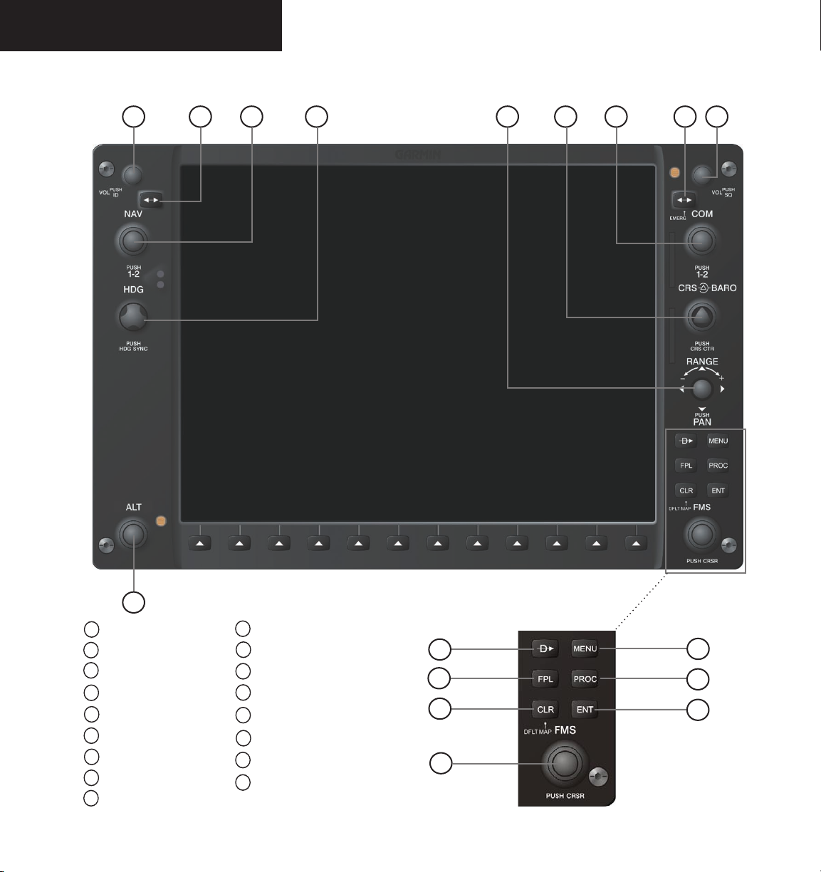
1.1 G1000 CONTROLS
1 2 4 6
3
5
7
8
9
17
Figure 1-1 G1000 Controls
1
NAV VOL/ID Control
2
NAV Frequency Toggle Key
3
NAV Frequency Selector
4
Heading Selector
5
Joystick
6
Course/Baro Selector
7
COM Frequency Selector
8
COM Frequency Toggle Key
9
COM VOL/SQ Control
2
10
Direct-to Key
11
Flight Plan Key
12
Clear Key
13
Flight Management System (FMS) knobs
14
Menu Key
15
Procedures Key
16
Enter Key
17
Altitude Reference Control
10
11
12
13
Garmin G1000 Cockpit Reference Guide for Mooney M20M & M20R
14
15
16
Page 17

SECTION 1 – INTRODUCTION
The G1000 controls and keys have been designed to
simplify operations and minimize workload and time to
access sophisticated functionality. The following provides
an overview of the primary function(s) for each key and
control.
• (1) NAV VOL / ID Control – Controls the NAV
audio level. Press to toggle the ident filter ON and
OFF. Volume increase and decrease is shown in the
field as a percentage.
• (2) NAV Frequency Toggle Key – Swaps the
standby NAV frequency and the active NAV frequency when pressed (the standby NAV frequency
is white whereas the active NAV frequency is green).
Note that NAV frequencies are shown as active only
when the HSI is set to either NAV1 or NAV2.
• (3) NAV Frequency Selector – The concentric
knobs tune the MHz (large) and kHz (small) standby
frequencies for the NAV receiver. Press on the small
knob to toggle the tuning cursor (cyan box) between
the NAV1 and NAV2 fields.
• (4) Heading Selector – Manually selects a heading.
When this knob is pressed, a window displaying a
digital heading momentarily appears to the left of the
Heading Indicator and the heading bug synchronizes
with the compass lubber line.
• (5) Joystick – Changes the map scale when rotated.
When pressed, it activates the map pointer.
• (6) CRS/BARO Selector – The large knob sets the
altimeter barometric pressure and the small knob
adjusts course. Course is adjustable when the HSI is
in NAV 1 & 2 or OBS/SUSP modes only). Pressing
the small knob centers the CDI on the currently
selected VOR.
• (7) COM Frequency Selector – The concentric
knobs tune the MHz (large) and kHz (small) standby
frequencies for the COM receiver. Pressing the
small knob toggles the tuning cursor (cyan box)
between the COM 1 and COM 2 fields.
• (8) COM Frequency Toggle Key – Swaps the
standby COM frequency and the active COM frequency. Pressing and holding this key for ten seconds automatically makes the 121.5 MHz emergency
frequency the active frequency.
• (9) COM VOL/SQ Control – Controls the COM
audio level. Pressing this knob turns the COM automatic squelch ON and OFF. Audio volume increase
and decrease is shown in the field as a percentage.
• (10) DIRECT-TO Key ( ) – Allows the user to
enter a destination waypoint and establish a direct
course to the selected destination (specified by
identifier, chosen from the active route, or taken
from the map cursor position).
• (11) FPL Key – Displays the active Flight Plan
Page for creating and editing the active flight plan
or accessing stored flight plans.
• (12) CLR Key (Default) – Erases information or
cancels an entry. To immediately display the Navigation Map Page, press and hold CLR (MFD only).
• (13) FMS Knobs – The concentric knobs are
used to select the page to be viewed (only on the
MFD)— the large FMS knob selects a page group
(MAP, WPT, AUX, NRST) while the small FMS
knob selects a specific page within the page group.
Pressing the small FMS knob turns the on-screen
cursor ON and OFF. When the cursor is on, data
may be entered in the different windows using a
combination of the small and large FMS knobs.
The large FMS knob is used to move the cursor on
the page. The small FMS knob is used to select
individual characters for the highlighted cursor location. When the G1000 displays a list of information
that is too long for the display screen, a scroll bar
appears along the right side of the display. The scroll
bar graphically indicates the number of additional
items available within the selected category.
Garmin G1000 Cockpit Reference Guide for Mooney M20M & M20R
3
Page 18

SECTION 1 – INTRODUCTION
Press the FMS/CSRS to activate the cursor and turn
the large FMS knob to scroll through the list.
• (14) MENU Key – Displays a context-sensitive
list of options. This options list allows the user to
access additional features or make settings changes
that relate to certain pages.
• (15) PROC Key – Selects approaches, departures
and arrivals from the flight plan. When using a
flight plan, available procedures for departure and/
or arrival airport are automatically suggested. If a
flight plan is not used, the desired airport, and the
desired procedure may be selected. The procedures
key selects IFR departure procedures (DPs), arrival
procedures (STARs) and approaches (IAPs) from
the database and loads them into the active flight
plan.
• (16) ENT Key – Accepts a menu selection or data
entry. The enter key is used to approve an operation
or complete data entry. It is also used to confirm
selections and information entries.
• (17) Altitude Reference Control – Sets the refer-
ence altitude in the window over the altimeter tape.
The large ALT knob selects thousands, the small
ALT knob selects hundreds.
1.2 SECURE DIGITAL CARDS
The GDU 1040 data card slots use Secure Digital (SD)
cards. SD cards are used for aviation database updates
and terrain database storage.
To install an SD card:
1. Press the card into place until it seats on the
internal connector and the front of the card is
flush with the face of the display bezel
To remove an SD card:
1. Gently press on the card to release the spring
latch and partially eject the card.
NOTE: Appendix A of the G1000 Pilot’s Guide
contains instructions on updating the aviation
database.
1.3 SYSTEM POWER-UP
The G1000 system is integrated with the aircraft electrical system and receives power directly from electrical
busses. See the Aircraft Flight Manual Supplement for
system start-up procedures.
Garmin G1000 PFD/MFD and supporting sub-systems include both power-on and continuous built-in test
features that exercise the processor, RAM, ROM, external
inputs and outputs to provide safe operation.
4
Garmin G1000 Cockpit Reference Guide for Mooney M20M & M20R
Page 19
SECTION 1 – INTRODUCTION
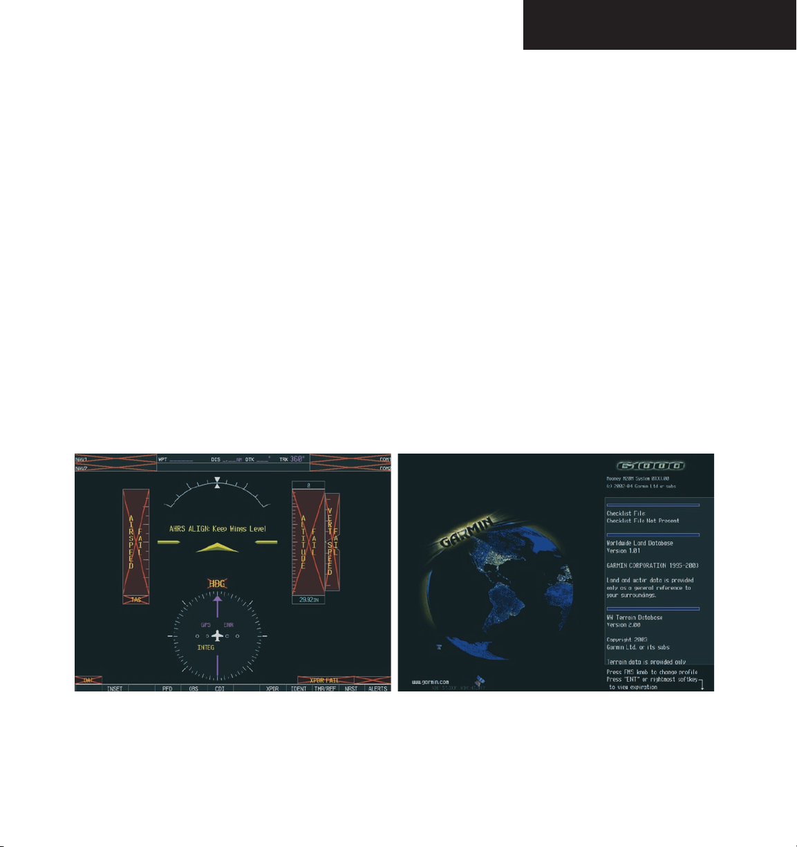
PFD Power Up
As the G1000 system begins to initialize, test annunciations are displayed to the pilot on the PFD, as shown in
Figure 1-2. All system annunciations should clear within one minute of power up. The PFD also displays the
‘AHRS ALIGN: Keep Wings Level’ message. The AHRS
should display valid attitude and heading fields within 1
minute of power up. The AHRS can align itself while the
aircraft taxis or during level flight.
MFD Power Up
The MFD Power-up Page displays general information
such as software version and database versions to the pilot
upon power-up of the G1000 system. The Power-up Page
displays the following data, shown in a scrolling list:
• System software version number.
• Copyright string.
• Checklist filename and copyright information.
• Land database name and version
• Terrain database information
• Obstacle database information
• Aviation database information (If the aviation data
base is out of date, then the pilot is forced to view
text that states the aviation database is out of date)
• Active Pilot Profile
-
Figure 1-2 G1000 Power-Up
Garmin G1000 Cockpit Reference Guide for Mooney M20M & M20R
5
Page 20

SECTION 1 – INTRODUCTION
1.4 INITIAL OPERATIONS
The pilot may wish to change the active pilot profile
(see the System Setup Section of the MFD Pilot’s Guide
for details).
When the Power-Up Page list has been reviewed for
currency (to ensure that no databases have expired), the
pilot is prompted to continue. The current database in
formation (which is loaded in the system) is displayed
(valid operating dates, cycle number and database type
indicated).
Press the
acknowledge the list information and proceed to the Navi
gation Map Page. When the system has acquired a sufficient number of satellites to determine a position, the
aircraft symbol appears showing your present position.
ENT key (or the right most softkey) to
1.5 BACKLIGHTING
The G1000 PFD and MFD displays use photocell technology to automatically adjust for ambient lighting conditions. Photocell calibration curves are pre-configured
to optimize display appearance through a broad range of
cockpit lighting conditions. PFD, MFD, and GMA 1347
bezel/key lighting is normally controlled directly by the
existing instrument panel dimmer bus.
If desired, the PFD and MFD display backlights
may be adjusted manually. PFD, MFD, and GMA 1347
bezel/key brightness can also be adjusted manually as
well. GMA 1347 bezel/key brightness is directly tied to
the MFD bezel/key adjustment. Section 2 provides instructions on how to manually adjust the backlighting.
1.6 REVERSIONARY MODE
flight instrumentation in place of traditional gyro instruments. Attitude, heading, airspeed, altitude, and vertical
speed are all shown on one display. The MFD shows a
full-color moving map with navigation information. Both
displays offer control over COM and NAV frequency selec-
tors, as well as heading, course/baro and altitude reference
functions. On the left of the MFD display, an Engine Indication System (EIS) cluster shows graphical depictions of
engine and airframe instrumentation. Figure 1-3 gives an
example of the G1000 system in normal mode.
-
tomatically enters reversionary mode. Figure 1-4 shows
an example where the PFD fails. In reversionary mode,
critical flight instrumentation is combined with engine instrumentation on the remaining display. Minimal navigation capability is also available on the reversionary mode
display.
activated by the pilot, if the system fails to detect a
display problem. The reversionary mode is activated
manually by pressing the large red button on the bottom
of the GMA 1347. Pressing the red reversionary mode
button again deactivates reversionary mode.
In normal operating mode, the PFD displays graphical
Should a failure occur in either display, the G1000 au
Reversionary display mode can also be manually
NOTE: The system alerts the pilot when backup
paths are utilized by LRUs. Refer to the Annunciations & Alerts Pilot’s Guide for further information regarding these and other system alerts.
-
6
Garmin G1000 Cockpit Reference Guide for Mooney M20M & M20R
Page 21
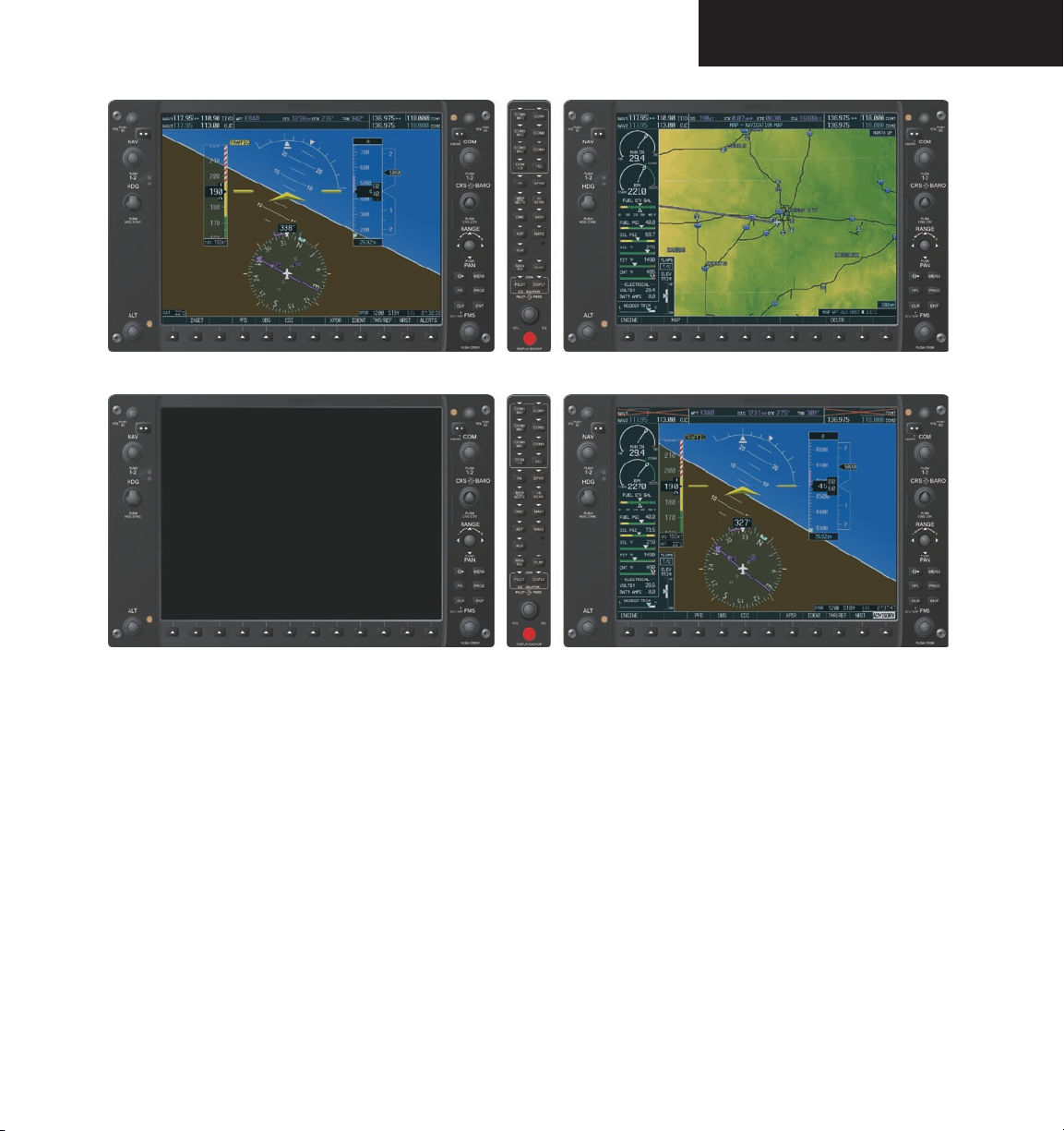
Figure 1-3 G1000 Normal Mode
SECTION 1 – INTRODUCTION
Figure 1-4 G1000 Reversionary Mode: Failed PFD
Garmin G1000 Cockpit Reference Guide for Mooney M20M & M20R
7
Page 22

SECTION 1 – INTRODUCTION
This page intentionally left blank.
8
Garmin G1000 Cockpit Reference Guide for Mooney M20M & M20R
Page 23

SECTION 2 – PFD
SECTION 2: PRIMARY FLIGHT
DISPLAY
This Cockpit Reference Guide describes the basic features of the Primary Flight Display (PFD) on the G1000
Integrated Cockpit System installed on Mooney aircraft.
The system consists of two 10.4 inch color flat panel displays. During normal operation, the left display is con
figured as a Primary Flight Display. See the PFD Pilot’s
Guide for PFD descriptions and operating procedures not covered in this Cockpit Reference Guide.
The PFD provides increased situational awareness by
replacing the traditional “six pack” of instruments in the
pilot’s panel with a easy to scan display that provides a
large horizon, airspeed, attitude, altitude, vertical speed,
navigation, communication, annunciation, terrain, traffic
and lightning information. The PFD will also control the
operation of the transponder, selecting NAV/COM fre
quencies and audio volume and many navigation features.
The operation of these features are explained in other supporting pilot’s guide documentation.
WARNING: In the event that the airspeed,
attitude, altitude or heading indications become
unusable please refer to the backup instruments.
-
-
The PFD displays the following:
• Navigation Frequency Window
• Navigation Status Bar
• Communication Frequency Window
• Airspeed Indicator
• True Airspeed Box
• Attitude Indicator
• Slip/Skid Indicator
• Horizontal Situation Indicator
• Bearing Pointers
• Bearing Information Windows
• Turn Rate Indicator
• Altimeter
• Altitude Reference Box
• Barometric Setting Box
• Vertical Deviation/Glideslope Indicator
• Marker Beacon Receiver Annunciations
• Vertical Speed Indicator
• Alerts Window
• Annunciation Window
• System Time Box
• Transponder Status Bar
• Outside Air Temperature Box
• Inset Map
• Direct-to Window
• Flight Plan Window
• Procedures Window
• Timer/References Window
• Nearest Airports Window
Garmin G1000 Cockpit Reference Guide for Mooney M20M & M20R
9
Page 24
SECTION 2 – PFD
1
2
3
4
5
6
17
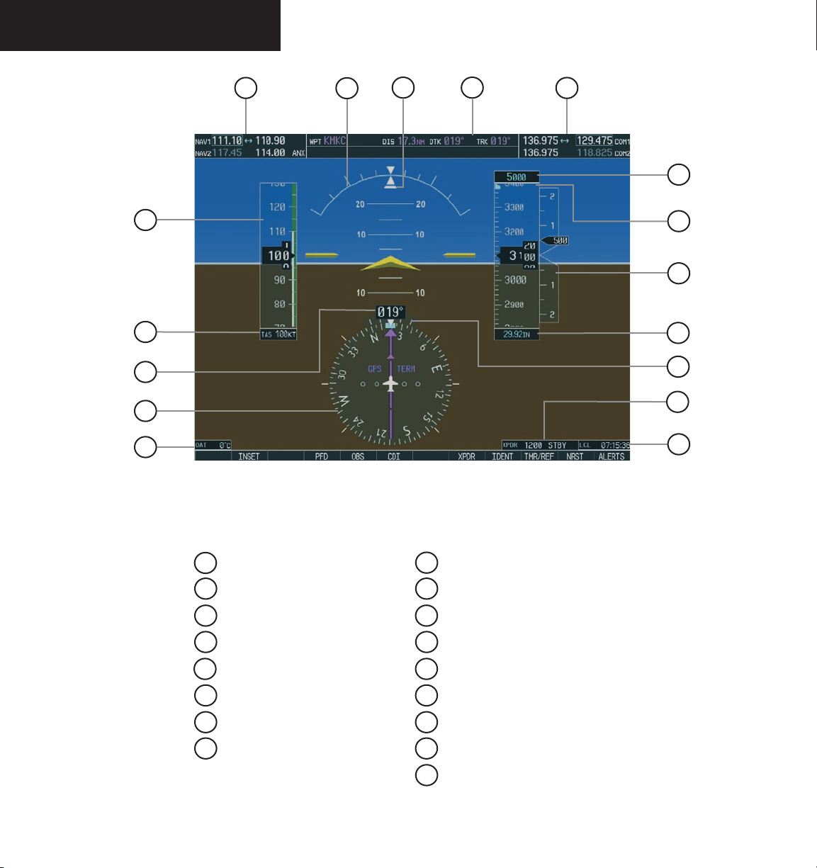
Figure 2-1 Default PFD Information
16
15
14
13
12
11
10
9
8
7
10
1
NAV Frequency Window
2
Airspeed Indicator
3
True Airspeed Box
4
Heading Box
5
Horizontal Situation Indicator
6
Outside Air Temperature Box
7
System Time Box
8
Transponder Status Bar
Garmin G1000 Cockpit Reference Guide for Mooney M20M & M20R
9
Turn Rate Indicator
10
Barometric Setting Box
11
Vertical Speed Indicator
12
Altimeter
13
Altitude Reference Box
14
COM Frequency Window
15
Navigation Status Bar
16
Slip/Skid Indicator
17
Attitude Indicator
Page 25
SECTION 2 – PFD
10
1
9
8
2
3
4
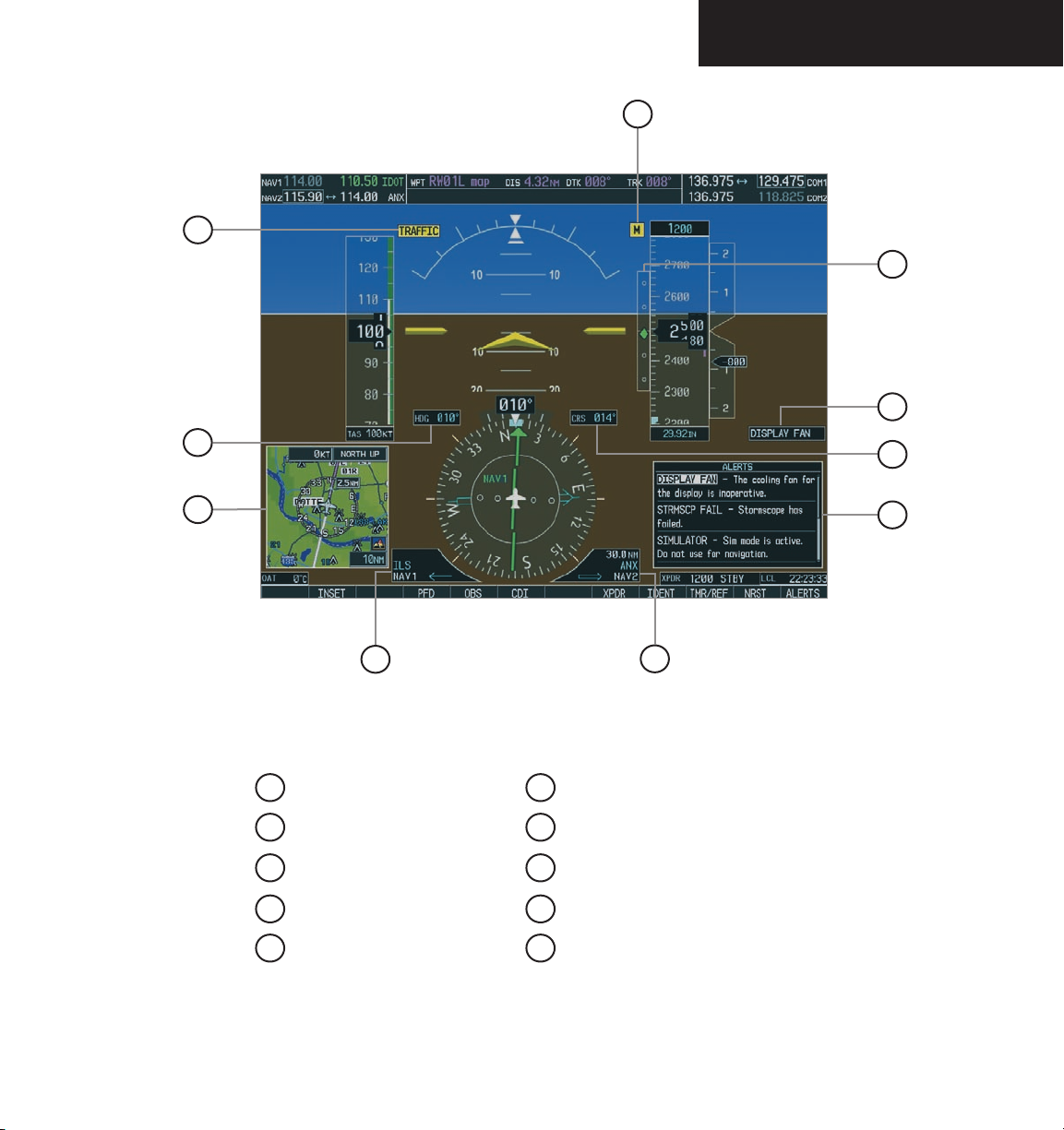
Figure 2-2 Additional PFD Information
1
Traffic Annunciation
2
Selected Heading Box
3
Inset Map
4
BRG1 Information Window
5
BRG2 Information Window
6
Alerts Window
7
Selected Course Box
8
Annunciation Window
9
Vertical Deviation/Glideslope Indicator
10
Marker Beacon Annunciation
5
7
6
Garmin G1000 Cockpit Reference Guide for Mooney M20M & M20R
11
Page 26
SECTION 2 – PFD
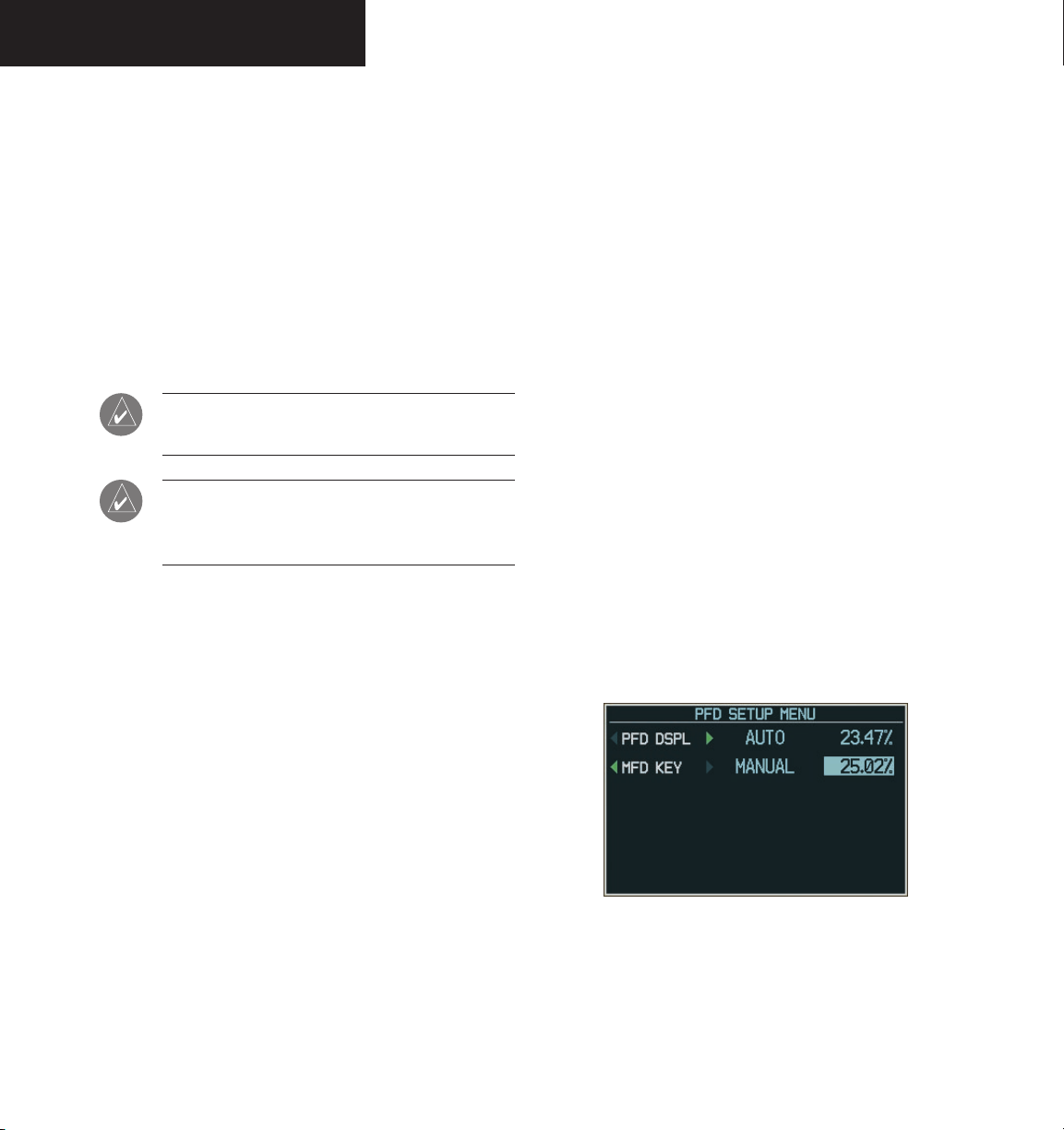
2.1 BACKLIGHTING
The backlighting of the display and the keys can be
adjusted for the PFD and MFD. The backlighting inten
sity ranges from 0.14% to 100.00%. Two modes exist for
adjustment:
• Auto - The G1000 adjusts the backlighting automatically with reference to the amount of light in
the cockpit (default setting).
• Manual - Allows the pilot to manually adjust the
backlighting.
NOTE: Except in reversionary mode, the back-
lighting can only be adjusted from the PFD.
NOTE: No other window can be displayed in the
lower right corner of the PFD when the MENU
key is pressed to change the backlighting.
To manually adjust the backlight for the
PFD and MFD:
-
To manually adjust the backlight for the
PFD and MFD keys:
MENU
1. Press the
key on the PFD to display
the PFD Setup Menu Window. ‘AUTO’ is now
highlighted next to PFD DSPL.
2. Turn the
Turn the
large FMS
small FMS
knob to highlight PFD DSPL.
knob in the direction of the
green arrow to display PFD KEY.
3. Turn the
Turn the
large FMS
small FMS
tion window. Turn the
‘MANUAL’, then press the
knob to highlight ‘AUTO’.
knob to display the selec-
FMS
knob to select
ENT
key.
4. With the intensity value now highlighted,
turn the
small FMS
backlighting, then press the
5. Turn the
large FMS
and turn the
knob to select the desired
ENT
key.
knob to highlight MFD DSPL
small FMS
knob in the direction of
the green arrow to display MFD KEY. Repeat
CLR
or
MENU
steps 3 and 4. Press the
key to
remove the window.
12
MENU
1. Press the
key on the PFD to display
the PFD Setup Menu window. ‘AUTO’ is now
highlighted next to ‘PFD DSPL’.
2. Turn the
small FMS
tion window. Turn the
‘MANUAL’, then press the
knob to display the selec-
FMS
knob to select
ENT
key.
3. With the intensity value now highlighted,
turn the
small FMS
backlighting, then press the
Turn the large FMS knob to highlight ‘AUTO’ next
4.
knob to select the desired
ENT
key.
to ‘MFD DSPL’ and repeat steps 2 and 3. Press
the
CLR
or
MENU
key to remove the window.
Garmin G1000 Cockpit Reference Guide for Mooney M20M & M20R
Figure 2-3 PFD Setup Menu
Page 27

SECTION 2 – PFD
2.2 SOFTKEY FUNCTION
When a softkey is turned on, its color changes to black
text on gray background and remains this way until it is
turned off, at that time it changes to white text on black
background. The
ALERTS softkeys change momentarily to black text on
gray background and automatically switches back to
white text on black background.
Softkey On
The PFD softkeys listed provide control over flight
management functions including GPS, NAV, terrain, traf
fic and lightning.
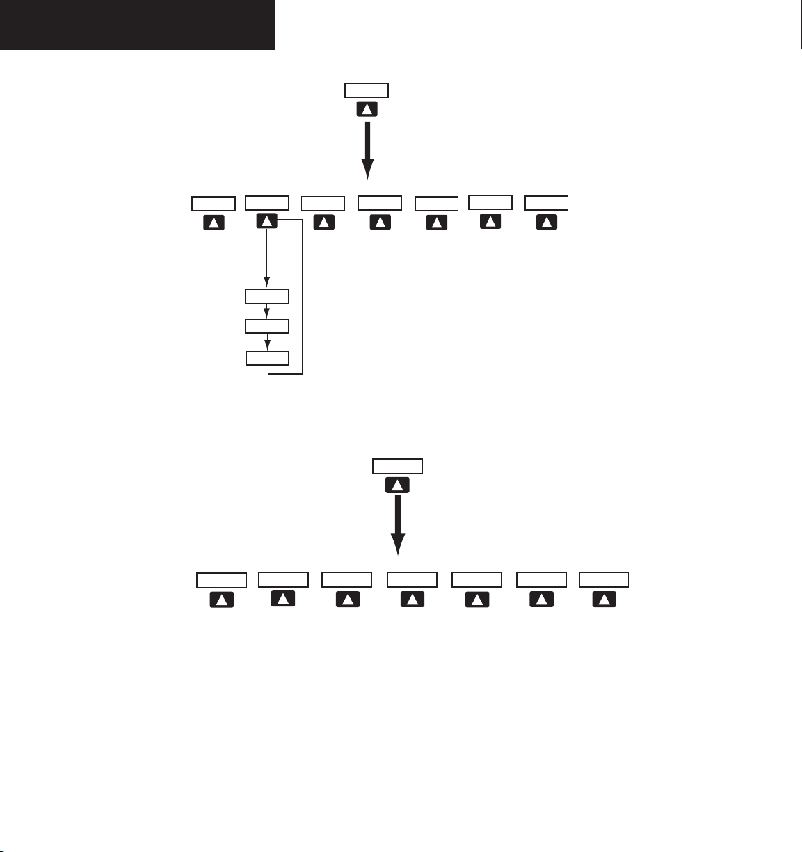
INSET – Press to display the Inset Map in the lower
left corner of the PFD.
OFF
DCLTR
desired amount of map detail. The declutter
level appears adjacent to the DCLTR softkey.
- No declutter: All map features are visible
- Declutter – 1: Declutters land data
- Declutter – 2: Declutters land and SUA data
- Declutter – 3: Declutters large NAV data remaining
TRAFFIC
map.
TOPO
coastlines, terrain, rivers, lakes, etc.) and
elevation scale on the inset map.
TERRAIN
on the inset map.
LTNG
the inset map (within a 200 nm radius of the
aircraft).
BACK
softkey configuration.
CDI, IDENT, TMR/REF, NRST and
Softkey Off
-
– Press to remove the Inset Map
(3) – Press momentarily to select the
– Press to display TIS traffic on the
– Press to display topographical data (i.e.,
– Press to display terrain information
– Press to display the lightning data on
– Press to return to the previous level
PFD – Press to display the additional softkeys for
additional configurations to the PFD.
METRIC
DFLTS
BRG1
360 HSI
ARC HSI
BRG2
STD BARO
BACK
– Press to display the current and reference altitudes in meters, in addition to feet.
Pressing the metric softkey also changes the
barometric setting to hectopascals.
– Press to reset default settings on the PFD.
– Press to display the BRG (bearing) 1 infor-
mation window.
OFF
– Press to remove BRG1 information
window.
NAV1
– Press to display NAV1 waypoint
frequency or identifier and DME information
in the BRG1 information window.
GPS
– Press to display GPS waypoint identifier
and DME information in the BRG1 information
window.
BACK
– Press to return to the previous level
softkeys.
– Press to display the 360° compass rose.
– Press to display the 140° viewable arcs.
– Press to display the BRG (bearing) 2 infor-
mation window.
NAV2
– Press to display NAV2 waypoint
frequency or identifier and DME information in
the BRG2 information window.
OFF
– Press to remove the BRG2 information
window.
BACK
– Press to return to the previous level
softkeys.
– Press to set the barometric pressure
to 29.92 inches of mercury (1013 hPa by
pressing the METRIC softkey).
– Press to return to the previous level softkeys.
Garmin G1000 Cockpit Reference Guide for Mooney M20M & M20R
13
Page 28
SECTION 2 – PFD
INSET
OFF
TOPO
TRAFFIC
TERRAIN
DCLTR
DCLTR-2
DCLTR-3
DCLTR-1
BACK
Press The BACK or OFF Softkey
To Return To The Top Level
Softkeys
ALERTS
PFD
METRIC
DFLTS
ARC HSI
360 HSI
STD BARO
BACK
Press the BACK softkey to return
to the top level softkeys
Press the DFLTS softkey to change the PFD
metric values to standard
ALERTS
14
Garmin G1000 Cockpit Reference Guide for Mooney M20M & M20R
Figure 2-4 PFD Softkeys (1 of 2)
Page 29
SECTION 2 – PFD
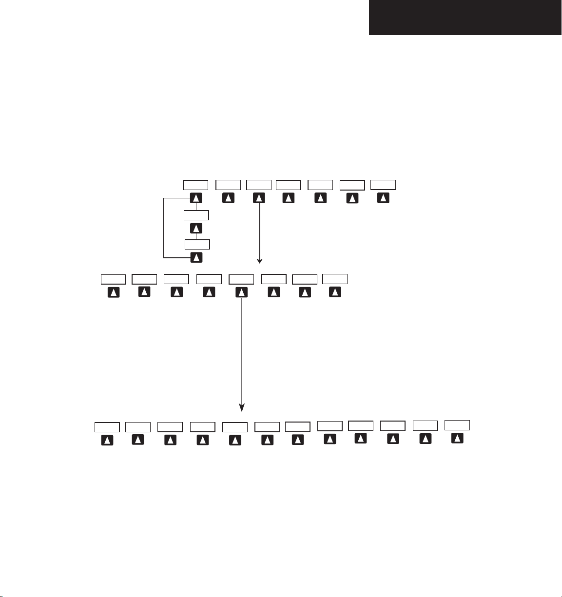
NRST
OBS
CDI
TMR/REF
IDENT
ALERTS
XPDR
STBY
ON
BACK
VFR
ALT
CODE
IDENT
0
1
6
3
2
4
5
7
IDENT
BACK
BKSP
Press the BACK softkey
to return to the top level
softkeys
Press the BACK
softkey
to return to
the top level
softkeys
ALERTS
ALERTS
CDI (NAV1)
CDI (NAV2)
Figure 2-4 PFD Softkeys (2 of 2)
Garmin G1000 Cockpit Reference Guide for Mooney M20M & M20R
15
Page 30

SECTION 2 – PFD
CDI – Press to change navigation mode on the CDI
between GPS NAV1 and NAV2.
OBS – Press to select OBS mode on the CDI when
navigating by GPS.
XPDR – Press to display the transponder mode selec-
tion softkeys.
STBY
– Press to select standby mode.
ON
– Press to select mode A.
ALT
– Press to select altitude mode.
VFR
– Press to automatically squawk 1200 (only
in the U.S.A.).
CODE
– Press to display transponder code selection
softkeys 0-7.
0 through 7
IDENT
– Press numbers to enter code.
– Press to provide special aircraft
position identification to Air Traffic Control
(ATC).
BKSP
– Press to remove numbers entered one
at a time.
BACK
– Press to return to the previous level
softkeys.
IDENT
– Press to provide special aircraft position
identification to Air Traffic Control (ATC).
BACK
– Press to return to the previous level
softkeys.
IDENT – Press to provide special aircraft position
identification to Air Traffic Control (ATC).
TMR/REF – Press to display the Timer/References
window.
NRST – Press to display the Nearest Airports
window.
ALERTS – Press to display the Alerts window.
16
Garmin G1000 Cockpit Reference Guide for Mooney M20M & M20R
Page 31

SECTION 2 – PFD
2.3 FLIGHT INSTRUMENTS
Airspeed Indicator
The Airspeed indicator displays airspeed on a rolling
number gauge using a moving tape. The following infor
mation is also displayed:
• Speed indication
• Speed ranges
• Airspeed trend vector
• Vspeed references
Airspeed Trend
Vector
Actual Airspeed
True Airspeed
Box
Figure 2-5 Airspeed Indicator
Vspeed
References
Speed Ranges
Speed Indication
The numeric labels and major tick marks on the mov
ing tape are marked at intervals of 10 knots, while minor
tick marks on the moving tape are indicated at intervals
of 5 knots. Speed indication starts at 20 knots, with 60
knots of airspeed viewable at one time. The actual air
speed is displayed inside the black pointer. The pointer
remains black until reaching never exceed speed (Vne), at
which point it turns red.
-
-
-
Speed Ranges
A color coded (white, green, yellow, and red) speed
range strip is located on the moving tape. The colors de
note flaps operating range, normal operating range, cau
-
tion range, and never exceed speed (Vne). A red range is
also present for low speed awareness. Refer to the Aircraft
Flight Manual Supplement (AFMS) for speed criteria.
Figure 2-6 Red Pointer at Vne
Airspeed Trend Vector
The vertical, magenta line extends up or down on the
airspeed scale located left of the numeric labels. The end
of the trend vector displays approximately what the air
speed will be in 6 seconds if the current rate of accelera
-
tion is maintained. The trend vector is absent if the speed
remains constant and if any data needed to calculate air
speed is not available due to a system failure.
Vspeed References
Vspeeds are set using the
TMR/REF softkey. Vr, Vx, Vy
and Glide are shown on the References window. When
active (ON), the Vspeeds are displayed at their respective
locations to the right of the airspeed scale (refer to the
Auxiliary windows section in this Pilot’s Guide to set and
display Vspeeds).
True Airspeed Box
The True Airspeed box is located below the Airspeed
indicator and displays the true airspeed in knots.
Garmin G1000 Cockpit Reference Guide for Mooney M20M & M20R
17
Page 32

SECTION 2 – PFD
Attitude Indicator
The attitude information displays over a virtual blue
sky and brown ground with a white horizon line. The
aircraft wing tips are represented by two yellow bars on
the horizon line. The yellow inverted “V” represents the
aircraft. The Attitude indicator displays the following information:
• Pitch indication
• Roll indication
• Slip/Skid indication
10
1
2
3
4
Pitch Indication
Major pitch marks and numeric labels at 10, 20, 30,
40, 50, 60, 70 and 80 degrees are shown above and be
low the horizon line. Minor pitch marks at 5, 15 and 25
degrees above the horizon line and 5, 15, 25, 35 and 45
degrees below the horizon line are shown. The horizon
line is part of the pitch scale. Red extreme pitch warning
chevrons pointing toward the horizon are displayed starting at 50 degrees above and 30 degrees below the horizon
line (refer to the figures on the next page).
1
Roll Pointer
9
8
7
6
2
Roll Scale
3
Horizon Line
4
Aircraft Symbol
5
Land Representation
6
Aircraft Wing Tips
7
Pitch Scale
18
8
5
Figure 2-7 Attitude Indicator
Garmin G1000 Cockpit Reference Guide for Mooney M20M & M20R
Slip/Skid Indicator
9
Sky Representation
10
Roll Index
Page 33

SECTION 2 – PFD
Roll Indication
Major tick marks at 30 and 60 degrees and minor tick
marks at 10, 20 and 45 degrees are shown to the left and
right on the roll scale. The inverted white triangle indi
cates 0 on the roll scale. Angle of bank is indicated by the
position of the roll pointer on the roll scale.
NOTE: Supplemental flight data such as the Inset
Map, Alerts and Annunciation Window disappear
from the PFD when pitch is more than +30˚
and less than -20˚ or when a 65˚ bank angle is
reached.
Figure 2-8 Attitude Indicator Nose High
Figure 2-9 Attitude Indicator Nose Low
Slip/Skid Indication
The Slip/Skid indicator resides beneath the roll pointer.
The indicator moves with the roll pointer and moves later
ally away from the pointer to indicate lateral acceleration.
A slip/skid is indicated by the location of the Slip/Skid indicator relative to the roll pointer. One Slip/Skid indicator
displacement is equal to one ball displacement when compared to a traditional Slip/Skid indicator.
-
Garmin G1000 Cockpit Reference Guide for Mooney M20M & M20R
19
Page 34

SECTION 2 – PFD
Altimeter
The Altimeter displays barometric altitude values in
feet on a rolling number gauge using a moving tape. The
Altimeter displays the following information:
• Altitude values
• Altitude reference bug
• Altitude trend vector
• Altitude reference box
• Barometric setting box
• Altitude alerter
• Metric display
Altitude Reference
Box
Altitude Reference Bug
Altitude Trend
Vector
Current Altitude
Altitude Reference Bug
The Altitude Reference Bug is displayed at the reference
altitude or the edge of the tape (whichever is closer to the
current altitude) to provide increased altitude awareness.
Altitude Trend Vector
The vertical, magenta line extends up or down the alti
tude scale located right of the numeric labels. The end of
the trend vector displays approximately what the altitude
will be in 6 seconds if the current rate of vertical speed is
maintained. The trend vector is absent if altitude remains
constant or if any data needed to calculate it is not available due to a system failure.
Altitude Reference Box
The Altitude Reference box displays the reference alti
tude in feet. The metric value, when selected, is displayed
on top the Altitude Reference box.
Barometric Setting Box
The Barometric Setting Box displays the barometric
pressure in inches of mercury (in Hg) or hectopascals
(hPa).
20
Barometric Setting
Box
Figure 2-10 Altimeter
Altitude Values
The numeric labels and major tick marks are shown
at intervals of 100 feet. Minor tick marks are at intervals
of 20 feet. The current altitude is displayed in the black
pointer.
Garmin G1000 Cockpit Reference Guide for Mooney M20M & M20R
To select barometric pressure:
1. Turn the large BARO (outer) knob to select
the desired setting.
Page 35

Altitude Alerting
Altitude alerting provides the pilot with a visual and
aural alert when approaching the reference altitude.
Although flight control systems use the same reference
altitude box the altitude alerter does, the altitude alerter
is not coupled to a flight control system and can func
tion without one. The visual annunciations appear in the
altitude reference box. Anytime the reference altitude is
changed, the altitude alerter is reset.
There is an altitude band set at +/- 1,000 ft. of the ref
erence altitude and a deviation band set at +/- 200 ft. of
the reference altitude. When the pilot climbs or descends
to the reference altitude an aural alert (single tone) sounds
and the reference altitude flashes (cyan on black) for 5
seconds then changes to black on cyan as the aircraft pass
es through +/- 1,000 ft. of the reference altitude.
When the aircraft passes within +/- 200 ft. of the ref
erence altitude, the reference altitude flashes (cyan on
black) again indicating that the aircraft is within the devia
tion band. Each time the pilot flies outside the deviation
band (+/- 200 ft. of the reference altitude), an aural alert
is generated and the reference altitude flashes (yellow on
black) for 5 seconds.
SECTION 2 – PFD
Figure 2-12 Altimeter within 1,000 ft. of Reference Altitude
Figure 2-11 Colors Associated with the Altitude Alerter
Garmin G1000 Cockpit Reference Guide for Mooney M20M & M20R
Figure 2-13 Altimeter within 200 ft. of Reference Altitude
21
Page 36

SECTION 2 – PFD
Metric Display
Reference and current altitude can be displayed in meters. The barometric pressure may also be displayed in
hectopascals.
To display altitude in meters and barometric
pressure in hectopascals:
1. Press the
PFD softkey to display the second
level softkeys.
2. Press the METRIC softkey to display altitude in
meters and barometric pressure in hectopascals.
BACK
Press the
softkey to return to the top level
softkeys.
Vertical Deviation/Glideslope Indicator
The Vertical Deviation/Glideslope Indicator is a window on the left side of the Altimeter. The window appears
when an ILS is tuned in the active NAV field (and selected
on the Audio Panel). A green diamond appears and acts
as your vertical deviation indication, just like a glideslope
needle on a conventional indicator.
Marker Beacon Annunciations
Marker Beacon Annunciations are displayed on the
PFD to the left of the Altitude Reference Box. Outer marker reception is indicated by a blue light. Middle marker
reception is indicated by a amber light. Inner marker reception is indicated by a white light (refer to the Audio
Panel Pilot’s Guide for more information).
Marker Beacon
Annunciation
22
Figure 2-14 Altimeter (Metric)
Garmin G1000 Cockpit Reference Guide for Mooney M20M & M20R
Vertical
Deviation/Glideslope
Indicator
Figure 2-16 Marker Beacon and Vertical Deviation
Page 37

Vertical Speed Indicator
The Vertical Speed Indicator displays the aircraft vertical speed with numeric labels and tick marks at 1,000 ft.
and 2,000 ft. in each direction on the non-moving tape.
Minor tick marks are at intervals of 500 ft.
SECTION 2 – PFD
Vertical Speed Pointer
The Vertical Speed Pointer displays the current vertical
speed and points to that speed on the non-moving tape. If
the rate of ascent is greater than 2,000 feet per minute the
pointer will appear at the top edge of the non-moving tape
and the number of feet per minute will appear inside the
pointer. If the rate of descent is greater than 2,000 feet per
minute a negative sign is displayed in the pointer (-2,000)
for negative (down) vertical speed and the pointer will appear at the bottom edge of the non-moving tape.
NOTE: Digits appear in the pointer when the
climb or descent rate is >100 fpm.
Vertical Speed
Pointer
Figure 2-16 Vertical Speed Indicator
Garmin G1000 Cockpit Reference Guide for Mooney M20M & M20R
23
Page 38

SECTION 2 – PFD
Horizontal Situation Indicator
The Horizontal Situation Indicator (HSI) displays a rotating compass card with letters at the cardinal points and
numeric labels every 30 degrees. Major tick marks are
at 10 degree intervals and minor tick marks for every 5
degrees. The HSI is displayed in a heading up orientation.
The HSI compass can be displayed as a 360° rose or 140°
arc by pressing the PFD softkey, followed by the 360 HSI
or the ARC HSI softkey. The HSI displays the following
information:
• Heading indication
• Turn Rate indicator
• Course Deviation Indicator
• Bearing pointers
• Bearing information windows
• Navigation source
Lateral Deviation
Scale
Course Deviation and
TO/FROM Indicator
Figure 2-17 ARC HSI
14
13
1
2
3
4
5
6
Figure 2-18 Horizontal Situation Indicator
Turn Rate Indicator
1
Lateral Deviation Scale
2
Navigation Source
3
Aircraft Symbol
4
Course Deviation Indicator
5
Rotating Compass Rose
6
OBS Mode
7
TO/FROM Indicator
8
Heading Bug
9
Course Pointer
10
Flight Phase
11
Turn Rate and Heading Trend Vector
12
Heading
13
Lubber Line
14
12
11
10
9
8
7
24
Garmin G1000 Cockpit Reference Guide for Mooney M20M & M20R
Page 39

SECTION 2 – PFD
Heading Indication
A digital reading of the current magnetic heading ap
pears on top of the HSI. A rotatable heading bug on the
compass rose and arc marks the desired heading. When
the pilot selects a heading, a digital reading will appear for 3
seconds in a box left of the lubber line, next to the HSI.
Figure 2-19 Selected Heading Box
NOTE: The heading displayed on the HSI is always
magnetic, even if the NAV ANGLE is set to ‘TRUE’
in the AUX System Setup Page on the MFD.
Turn Rate Indicator
The Turn Rate Indicator resides directly above the rotating compass card. Each tick mark is at 9 (half standard
rate) and 18 (standard rate) degrees to the left and right of
the lubber line. A wide magenta line displays the current
turn rate up to 24 degrees. A magenta arrowhead appears
at 25 degrees and disappears at 24 degrees. This trend
vector provides the pilot with a 6 second prediction of
what the heading will be at the present turn rate.
Course Deviation Indicator
The HSI contains a course deviation indicator (CDI),
with a course pointer arrow, TO/FROM arrow, a sliding
deviation bar and scale. The course pointer is a single
line arrow (GPS and NAV1) or double line arrow (NAV2),
which points in the direction of the set course. The TO/
FROM arrow rotates with the course pointer and is dis
played when the active navaid is received. The sliding
deviation bar moves left or right from the course pointer
along a scale to display aircraft position relative to the
course. When the pilot selects a course, a digital reading
will appear for 3 seconds in a box right of the lubber line,
next to the HSI.
Figure 2-21 Selected Course Box
The CDI has angular limits exactly the same as a mechanical CDI when coupled to a VOR or LOC. When
coupled to GPS, the full scale limits for the CDI are defined by a GPS derived distance (5.0, 1.0 or 0.3 nm). The
CDI scale automatically adjusts to the desired limits based
upon the current phase of flight (enroute 5.0 nm, terminal
area 1.0 nm or approach 0.3 nm). The desired GPS scale
settings may be selected manually from the MFD (refer to
the MFD Pilot’s Guide).
Figure 2-20 Turn Rate Indicator and Trend Vector
Garmin G1000 Cockpit Reference Guide for Mooney M20M & M20R
25
Page 40

SECTION 2 – PFD
Bearing Pointers and Information Windows
There are 2 bearing pointers available, 1 or 2 can be
displayed on the HSI. Pressing the PFD softkey provides
access to the BRG1 and BRG2 softkeys. BRG1 pointer is
a single cyan (light blue) line with an open arrowhead at
the end. BRG2 pointer is a double cyan (light blue) line
with an open arrowhead at the end. The bearing point
ers never override the CDI. When one or more bearing
pointers are displayed (but not necessarily visible if there
is no data available), a white ring is presented around the
center of the compass rose to visually separate the bearing
pointer(s) from the CDI.
When a bearing pointer is displayed it’s associated
information window is also displayed. BRG1 information window is displayed to the lower left of the HSI
and includes the bearing source (NAV1), a pointer icon,
frequency and distance (NAV1 and GPS) to the bearing
source. BRG2 information window is displayed to the
lower right of the HSI and includes the bearing source
(NAV2), a pointer icon, frequency and distance (NAV2) to
the bearing source.
If GPS is the bearing source, the active waypoint identifier is displayed in lieu of a frequency. If an active waypoint is not selected, the bearing pointer is removed from
the HSI and “NO DATA” is displayed in the information
window.
If the NAV radio is the bearing source and is tuned to
an ILS frequency, the bearing pointer is removed from the
HSI and the frequency is replaced with “ILS”. If the NAV
radio is not receiving the tuned VOR station, the bearing
pointer is removed from the HSI and the frequency displayed in the information window is replaced with “NO
DATA”.
When NAV1 or NAV2 is the selected bearing source,
the frequency is replaced by the station identifier when
the station is in range.
Bearing 2
Pointer
Bearing 1
Information
Window
Figure 2-22 HSI with Bearing Information
Distance from
Waypoint
Waypoint
Identifier
Bearing
Source
Figure 2-23 BRG1 Information Window
Pointer
Icon
Figure 2-24 BRG2 Information Window
Bearing 1
Pointer
Bearing 2
Information
Window
Pointer
Icon
Distance from
Waypoint
Waypoint
Identifier
Bearing
Source
26
Garmin G1000 Cockpit Reference Guide for Mooney M20M & M20R
Page 41

SECTION 2 – PFD
Navigation Source
The HSI can display two sources of navigation, GPS
or NAV (VOR, localizer, and glideslope). In GPS mode
the flight plan legs are sequenced automatically. Enabling
OBS mode suspends auto sequencing of waypoints, but
retains the current “active to” waypoint as your navigation
reference even after passing the waypoint. When OBS is
disabled the GPS returns to normal operation, with auto
matic sequencing of waypoints. OBS mode also allows
the pilot to set the desired course TO/FROM a waypoint.
Color indicates the current navigation source, magenta
(for GPS ) or green (for NAV). As the user crosses the
MAP, “SUSP” appears on the HSI in place of OBS and the
OBS softkey now reads “SUSP”, indicating that automatic
sequencing of approach waypoints is suspended at the
MAP. A yellow ‘INTEG’ and ‘WARN’ may appear on the
HSI when the following occurs:
• INTEG – RAIM is not available
• WARN – GPS detects a position error
To change between navigation sources:
1. Press the
CDI softkey to change from GPS to
NAV1. This will place the cyan tuning box over
the NAV1 standby frequency in the upper left
corner of the PFD.
2. Press the
CDI softkey again to change from
NAV1 to NAV2. This will place the cyan tuning
box over the NAV2 standby frequency.
To enable/disable OBS mode while navigating
with GPS
1. Press the
:
OBS softkey to select OBS Mode.
2. Turn the small CRS knob to select the desired
course TO/FROM the waypoint.
3. Press the OBS softkey again to return to normal
operation.
3. Press the
GPS.
CDI
softkey a third time to return to
Garmin G1000 Cockpit Reference Guide for Mooney M20M & M20R
Figure 2-25 GPS INTEG, GPS SUSP, NAV1 and NAV2
27
Page 42

SECTION 2 – PFD
2.4 COMMUNICATION, NAVIGATION & SURVEILLANCE
Communication Frequency Window
The Communication Frequency window provides the
control and display of dual VHF Radio Communication
Transceivers (COM1 and COM2). The Communication
Frequency window displays the following information:
• COM1 and COM2 active and standby frequencies
• Color coded indication of the active COM transceiver
NOTE: Operating procedures for the Communica-
tion Frequency window are located in the VHF
NAV/COM Pilot’s Guide.
Navigation Frequency Window
The Navigation Frequency window provides the control and display of dual VOR/ILS receivers (NAV1 and
NAV2). The Navigation Frequency window displays the
following information:
• NAV1 and NAV2 active and standby frequencies
• NAV1 and NAV2 identifier, if the active NAV1 or
NAV2 frequency is a valid, identified frequency
• Color coded indication of the active NAV receiver
NOTE: Operating procedures for the Navigation Frequency window are located in the VHF NAV/COM
Pilot’s Guide.
Selected COM
Frequency
(Green)
Figure 2-26 Communication Frequency Window
NAV Receivers
Active COM
Frequency Field
Frequency
Toggle Arrow
Frequency
Tuning Box
Standby NAV
Frequency Field
Figure 2-27 Navigation Frequency Window
Frequency
Tuning Box
Standby COM
Frequency Field
Active NAV
Frequency Field
Frequency
Toggle Arrow
COM Radios
Selected NAV
Frequency
(Green)
28
Garmin G1000 Cockpit Reference Guide for Mooney M20M & M20R
Page 43

Navigation Status Bar
The Navigation Status Bar resides at the top of the PFD
and displays valuable information while flying a route.
The following information is displayed:
• The next waypoint in the active flight plan
• Distance to the next waypoint (DIS)
• Desired track to the next waypoint (DTK)
• Current track angle (TRK)
• GPS Navigation Annunciations
NOTE: The fields in the PFD Navigation Status
Bar cannot be changed.
Distance to
Next Waypoint
Next Waypoint
Desired Track
To
Next Waypoint
SECTION 2 – PFD
Current Track
Figure 2-28 Navigation Status Bars
Figure 2-29 Navigation Status Bar Message
Garmin G1000 Cockpit Reference Guide for Mooney M20M & M20R
29
Page 44

SECTION 2 – PFD
Transponder Status Bar
The Transponder Status Bar displays the transponder
code, reply symbol, and mode of operation. TIS (Traffic
Information System) surveillance data up-linked by Air
Traffic Control (ATC) radar through the GTX33 Mode S
Transponder appears on the Inset Map (PFD), Navigation
and Traffic Map Pages on the MFD (refer to the MFD Pilot’s
Guide). If the transponder is configured with
Airborne Determination, normal operation begins when
lift off is sensed. When the aircraft is on the ground, the
window automatically displays “GND”. The transponder
does not respond to ATCRBS interrogations when GND is
annunciated. If a delay time is set in Configuration Mode,
the transponder waits a specified length of time after land
ing before changing to
GND mode.
Transponder Operation
Pressing the
XPDR softkey displays the second-level
softkeys:
• STBY – Selects standby mode. When in standby
mode, the transponder does not reply to any
interrogations.
• ON – Selects Mode A. In this mode, the transponder replies to interrogations, as indicated by the
Reply Symbol (R). Replies do not include altitude
information.
• ALT – Selects Mode C. In ALT mode, the tran-
sponder replies to identification and altitude
interrogations as indicated by the Reply Symbol
(R). Replies to altitude interrogations include the
standard pressure altitude received from an exter
nal altitude source, which is not adjusted for baro
metric pressure. The ALT mode may be selected
in aircraft not equipped with an optional altitude
encoder; however, the reply signal will only reply
to mode A interrogations. The transponder also
responds to interrogations from TCAS equipped
aircraft.
• VFR – Sets the transponder code to the pre-pro-
Automated
-
-
-
grammed VFR code selected in Configuration
Mode (this is set to 1200 at the factory).
• CODE – Displays the transponder code selection
softkeys, which includes the digits 0-7 and BKSP.
• IDENT – Pressing the IDENT softkey activates
the Special Position Identification (SPI) Pulse for
18 seconds, identifying the transponder return on
the ATC screen.
Transponder Code Selection
Transponder code selection is performed with eight
softkeys (0-7) providing 4,096 active identification codes.
Pushing one of those keys begins the code selection se
quence. The new code is activated five seconds after the
fourth digit is entered. Pressing the BKSP softkey removes
one digit at a time until the status bar is empty (refer to the
Mode S Transponder Pilot’s Guide).
Figure 2-30 Transponder Status Bar
2.5 ALERTS AND ANNUNCIATIONS
Alerts and Annunciations that appear on the PFD are
described in detail in Appendix A of this Cockpit Reference Guide.
30
Garmin G1000 Cockpit Reference Guide for Mooney M20M & M20R
Page 45

SECTION 3 – AUDIO PANEL
SECTION 3: AUDIO PANEL
The GMA 1347 Audio Panel features the following
three (3) major groups of keys in descending order, as
shown in Figure 3-1:
• Communication keys
• Navigation keys
• Intercom keys
Each key is labeled with a white inscription in its cen
ter, indicating the name of the associated channel. The
triangular key annunciator lights are white when illuminated and point to the corresponding keys.
The dual knob located at the bottom of the unit con
trols volume as well as squelch threshold levels. The
small knob adjusts the volume/squelch level associated
with the pilot channel, while the large knob adjusts the
volume/squelch level associated with the copilot/passenger channels. The red button situated below the dual volume/squelch knob controls backup (reversionary) mode
selection.
NOTE: A complete audio panel description with
full operating procedures is presented in the
G1000 Audio Panel Pilot’s Guide.
NOTE: Refe r to the Audio Pane l Pilo t’s
Guide Supplement for Mooney for addit i on a l i n f or m at i on r eg a r d i n g t h e
GMA 1347 as installed in Mooney aircraft.
-
-
3.1 FRONT PANEL CONTROLS
• Transceiver audio selector keys
(COM1, COM2, COM3)
• Transmitter (audio/mic) selection keys
(COM1 MIC, COM2 MIC, COM3 MIC)
• Split COM key
(COM 1/2)
• Dedicated telephone interface key
(TEL)
• Passenger address key
(PA)
• Speaker key
(SPKR)
• Marker beacon receiver audio select/mute key
(MKR/MUTE)
• Marker beacon receiver high sensitivity key
(HI SENS)
• Aircraft radio audio selector keys
(NAV1, NAV2, ADF, DME, AUX)
• Intercom manual squelch mode key
(MAN SQ)
• Digital recording playback key
(PLAY)
• Intercom system (ICS) isolation mode keys
(PILOT, COPLT)
• Volume/squelch knob
(VOL/SQ)
• Backup (reversionary) mode button
(DISPLAY BACKUP)
Garmin G1000 Cockpit Reference Guide for Mooney M20M & M20R
31
Page 46

SECTION 3 – AUDIO PANEL
Transmitters
Split COM
Passenger Address
Marker Beacon/Mute
Aircraft Navigation Radio Audio
Manual Squelch
Transceiver Audio
Telephone
Speaker
Marker Beacon Signal Sensitivity
Aircraft Navigation Radio Audio
Digital Recording Playback
ICS Isolation
32
VOL/SQ
VOL Annunciation
Figure 3-1 Front Panel Controls
Garmin G1000 Cockpit Reference Guide for Mooney M20M & M20R
SQ Annunciation
Reversionary Mode
Page 47

SECTION 3 – AUDIO PANEL
Microphones
The GMA 1347 features six (6) different microphone
channeling modes:
• COM1 MIC
• COM2 MIC
• COM3 MIC
• COM 1/2 (Split COM)
• PA
• COM 1/2 and PA (Split COM and PA)
NOTE: A push-to-talk (PTT) switch must be
pressed to open the selected output channel.
Each audio panel can accept up to six (6) microphone
inputs, thus allowing for a two-person crew and up to
four (4) passenger intercom stations in the aircraft.
Mono/Stereo Headsets
The GMA 1347 can accommodate up to six (6) headsets (pilot, copilot and up to four (4) passengers).
In Configuration mode, headset audio level can be ad
justed above or below a nominal value for MUSIC 1, MUSIC
2, UNSWITCHED 1, UNSWITCHED 2, UNSWITCHED
3 and ALTITUDE WARNING. Please consult a Garminauthorized service center for additional information.
Unmuted/Unswitched Inputs
The unit provides four (4) unmuted/unswitched inputs that are always presented to the headsets or speakers
connected to the panel. These inputs are the following
aural warnings:
• ALT warning
• UNSWITCHED 1
• UNSWITCHED 2
• UNSWITCHED 3
NOTE: The use of stereo headsets is highly
recommended. However, if monaural headsets
are plugged into stereo jacks that do not each
have a switch installed, the unit will not be damaged.
Use of a monaural headset in a stereo jack shorts the
right headset channel output to ground. Thus, a person
listening on a monaural headset only hears the left channel in both ears. If a monaural headset is used at one of
the passenger positions, any other passenger listening on
a stereo headset hears audio in the left ear only, unless the
headset has a mono/stereo switch and the latter is set to
mono.
Garmin G1000 Cockpit Reference Guide for Mooney M20M & M20R
33
Page 48

SECTION 3 – AUDIO PANEL
3.2 UNIT OPERATION
Power-up Settings
Upon power-up, the unit undergoes a self-test during
which all panel annunciator lights illuminate for approxi
mately two (2) seconds. Once the self-test is completed,
the settings are restored to the settings that were current
before the unit was last powered off. For example, if the
COM1 MIC, COM1, COM2, SPKR, NAV1, NAV2,
MKR/MUTE, HI SENS, and MAN SQ keys were selected
when the unit was last powered off, these keys will be
automatically re-selected when the unit is powered back
on.
Fail-safe Mode
In the event of an audio panel failure, the unit switches
to fail-safe mode. In fail-safe mode, fail-safe audio is directed to the pilot’s headset (left channel only). Fail-safe
mode bypasses the GMA 1347 circuits, with the exception
of the relay that switches the pilot’s MIC and the pilot’s
headset directly to COM1.
-
Selecting Keys
For all keys with the exception of the MKR/MUTE
and PLAY keys, pressing a key activates the corresponding channel and illuminates the associated triangular annunciator light.
Deselecting Keys
For all keys with the exception of the COM MIC,
MKR/MUTE and PLAY keys, pressing the key again de-
activates the corresponding channel and turns off the associated annunciator light.
NOTE: Operational details on the COM MIC,
MKR/MUTE and PLAY keys as well as the DISPLAY BACKUP button are provided later in this
manual.
Lighting
LED key backlighting is controlled automatically by
the MFD (the PFD assumes control should the MFD fail).
NOTE: When a key is active during normal opera-
tions, its corresponding annunciator LED is lit.
34
Garmin G1000 Cockpit Reference Guide for Mooney M20M & M20R
Page 49

SECTION 3 – AUDIO PANEL
Transceiver Keys
As illustrated below, the following eight (8) transceiv-
er keys appear at the top of the GMA 1347 front panel:
COM1 MIC, COM2 MIC, COM3 MIC, COM 1/2,
COM1, COM2, COM3, and TEL. COM audio can be
selected by either pressing the desired COM key or by
pressing the corresponding COM MIC key.
NOTE: A PTT switch must be pressed to allow
all microphone transmissions.
Pressing a COM Key
Pressing COM1, COM2, or COM3 selects the corresponding radio as the active audio source. Each audio
source can be selected independently by pressing COM1,
COM2, or COM3. If selected in this manner, the audio source remains selected independently of the active
microphone source selection. The active COM audio is
always heard through the headsets, and any combination
of audio sources can be selected simultaneously.
During COM signal reception, a white RX inscrip
-
tion appears next to the corresponding COM frequency
on both the PFD and the MFD for the duration of the
reception.
Keying a Microphone
When a microphone is keyed, the active transceiver
MIC key annunciator blinks approximately once per second to indicate that the transmission is active, and a white
TX inscription appears next to the corresponding COM
frequency on both the PFD and the MFD for the duration
of the transmission.
Figure 3-2 Transceivers
Pressing a COM MIC Key
Pressing COM1 MIC, COM2 MIC, or COM3 MIC
selects the corresponding radio as the active microphone
source (i.e., as the primary COM radio) and highlights
the corresponding COM frequency in green in the active
frequency field of the PFD and MFD.
Only one microphone source can be selected at a time.
Thus, if COM1 MIC is pressed when COM2 MIC is al
ready selected, COM2 MIC is automatically deactivated
and the COM2 MIC annunciator light is turned off. The
corresponding audio selection key (in this case, COM1)
becomes automatically selected if it is not already selected
at the time.
Garmin G1000 Cockpit Reference Guide for Mooney M20M & M20R
-
When no further aircraft radio activity is detected by
the unit, the amount of ambient background noise from
the radios is further reduced by the MASQTM (Master Avionics Squelch) circuit (information on MASQ
TM
is present-
ed later in this manual).
NOTE: Audio level of the selected COM radio(s)
is controlled by the COM radio volume control
located on both the PFD and MFD (see G1000
VHF NAV/COM Pilot’s Guide for more information).
35
Page 50

SECTION 3 – AUDIO PANEL
COM Swap
The GMA 1347 allows for the use of a remotely mounted switch to alternately transfer the active microphone
between COM1 MIC and COM2 MIC. The COM swap
switch is typically mounted on the yoke or control stick.
If COM1 MIC is the active microphone (i.e., both COM1
MIC and COM1 keys are annunciated), pressing the COM
swap switch transfers the active microphone from COM1
MIC to COM2 MIC (i.e., both COM1 MIC and COM1
keys become deselected, and COM2 MIC and COM2
keys become annunciated). Pressing the switch has no ef
fect if COM3 is the active transceiver or if COM 1/2 (split
COM) is activated.
Please consult a Garmin-authorized service center for
details on the remote COM swap option.
Split COM
Pressing the COM 1/2 key toggles the state of the split
COM function. During split COM operation, the COM1,
COM1 MIC, COM2 and COM2 MIC keys are annunciated and thus active.
NOTE: Split COM performance varies significantly
across installations and is affected by both the
distance between the antennas and the separation of the tuned frequencies. In small aircraft
particularly, receiver sensitivity is typically
reduced and squelch breaks are affected. Each
installation should be individually examined to
determine the expected performance of split
COM.
PA Function
The passenger address function is provided via the PA
key. Push-to-talk (PTT) must be used to deliver PA announcements.
NOTE: PA volume is adjustable in Configuration
mode.
36
When the COM 1/2 key is selected, COM1 becomes
dedicated solely to the pilot for MIC/audio, while
COM2
becomes dedicated to the copilot for MIC/audio. The
COM1 MIC annunciator blinks when the pilot’s microphone is keyed. The COM2 MIC annunciator blinks
when the copilot’s microphone is keyed.
In this mode, both the pilot and the copilot can
simultaneously transmit over separate radios. Note that,
while the pilot can still monitor
COM3, NAV1, NAV2,
DME, ADF, AUX and MKR audio as selected, the copilot is
only able to monitor/hear COM2.
Split COM mode is cancelled by pressing the COM 1/2
key.
Garmin G1000 Cockpit Reference Guide for Mooney M20M & M20R
Page 51

SECTION 3 – AUDIO PANEL
Split COM and PA
When in split COM mode (COM 1/2 activated), the
copilot can make PA announcements while the pilot continues to use COM1 independently. When the PA key is
pressed after the split COM mode is activated, the copilot’s
microphone is output over the cabin speaker when keyed.
Pressing the PA key again returns the copilot to normal
split COM operation.
NOTE: Only the copilot can make PA announce-
ments when in split COM and PA mode.
Speaker Output
Pressing the SPKR key selects the aircraft radios to be
output to the cabin speaker. Pressing the SPKR key again
deselects the speaker mode. When SPKR is selected, any
and all of the following radios can be heard over the cabin
speaker: COM1, COM2, COM3, NAV1, NAV2, DME,
ADF, and AUX.
Speaker output is muted when the PTT switch is
keyed. All of the unswitched/unmuted radio inputs can
be heard over the speaker. In Configuration mode, speaker audio level is adjustable above and below a nominal
value. Please consult a Garmin-authorized service center
for details.
Figure 3-3 Split COM, PA and Speaker
Garmin G1000 Cockpit Reference Guide for Mooney M20M & M20R
37
Page 52

SECTION 3 – AUDIO PANEL
3.3 MARKER BEACON RECEIVER
Description and Operation
The GMA 1347 provides a marker beacon receiver to
be used as part of an ILS approach. In addition to the
normal marker beacon receiver functions, the GMA 1347
provides an audio muting capability. The marker beacon receiver is always “ON” and receives at 75 MHz.
The receiver detects three (3) tones associated with the
outer, middle and inner approach markers, respectively,
and illuminates the appropriate marker beacon indica
tor lights located to the left of the Altimeter on the PFD.
The outer marker signal frequency is 400 Hz, and a blue
light indicates its reception. The middle marker signal
frequency is 1,300 Hz, and an amber light indicates its
reception. The inner marker signal frequency is 3,000
Hz, and a white light indicates its reception.
When the
MKR/MUTE key is selected, the
corresponding annunciator light becomes illuminated
and the audio signal can be heard over the headsets.
-
The marker beacon audio level is aligned at the factory
to produce its rated audio output. Audio output level is
also adjustable in Configuration mode. Please consult a
Garmin-authorized service center for details.
NOTE: The unit provides output for driving
external marker beacon lamps and it provides
a middle marker sense output for use with an
autopilot.
Marker Beacon Signal Augmentation
The HI SENS key can be pressed to augment marker
beacon signal reception sensitivity. The HI SENS function
is typically used either over airway markers or to receive
an earlier indication of a nearing outer marker during an
approach.
The middle marker sense indicator provides input to
the autopilot.
The lamp and audio keying of the marker beacon re
ceiver are summarized in Table 3-1.
-
38
When the
MKR/MUTE key is annunciated and a
marker beacon tone is received, pressing the MKR/MUTE
key mutes the audio but does not affect the
corresponding
annunciator light. The audio returns when the next (different) marker signal is received. If the MKR/MUTE key
is pressed while the marker beacon audio is muted, the
marker audio becomes deactivated and the MKR/MUTE
annunciator light is turned off.
NOTE: The marker beacon receiver lights operate
independently of the marker beacon audio and
cannot be turned off.
Garmin G1000 Cockpit Reference Guide for Mooney M20M & M20R
Figure 3-4 Marker Beacon
NOTE: The marker beacon signal sensitivity
threshold can be set in Configuration mode.
Please consult a Garmin-authorized service
center for details.
Page 53

SECTION 3 – AUDIO PANEL
Beacon Audio Frequency Audio Keying Rate Lamp Color
Outer Marker
Middle Marker
Airway/Inner Marker
Inner Marker Middle Marker Outer Marker
400 Hz — — — 2 dashes per second Blue
1,300 Hz • — • —
95 dot-dash combinations
per minute
Amber
3,000 Hz • • • • 6 dots per second White
Table 3-1 Marker Beacon Signal Characteristics
Figure 3-5 Marker Beacon Signal Indicator Lights on the PFD
Garmin G1000 Cockpit Reference Guide for Mooney M20M & M20R
39
Page 54

SECTION 3 – AUDIO PANEL
3.4 RADIO INPUTS
Pressing DME, ADF, AUX, NAV1, or NAV2 selects
the corresponding audio source and activates the annunciator. Pressing the selected audio source key again deselects this audio source. Selected aircraft audio can be
heard over the appropriate headset and over the speakers
if SPKR is selected. Note that all aircraft radio keys can
be selected concurrently.
If desired, the
disabled. Please consult a Garmin-authorized service center for details.
DME, ADF and AUX channels may be
When no further aircraft radio activity is detected by
the unit, the amount of ambient background noise from
the radios is further reduced by the Master Avionics
Squelch (MASQTM) circuit.
40
Figure 3-6 Aircraft Radios
Garmin G1000 Cockpit Reference Guide for Mooney M20M & M20R
Page 55

3.5 INTERCOM SYSTEM (ICS) ISOLATION
The intercom system (ICS) provides four (4) isolation
modes: ALL, PILOT, COPILOT, and CREW. The desired mode can be selected or deselected using the PILOT
and COPLT keys.
SECTION 3 – AUDIO PANEL
Figure 3-7 ICS Isolation
PILOT Mode
PILOT mode is selected when only the PILOT key is
annunciated. In PILOT mode, the pilot can hear the selected radios, whereas the copilot and passengers can only
communicate with each other and hear MUSIC 1.
COPILOT Mode
COPILOT mode is selected when only the COPLT key
is annunciated. In COPILOT mode, the copilot is isolated
from everyone and can only hear MUSIC 2. In this mode,
the pilot and passengers can hear the selected radios as
well as MUSIC 1 and can also communicate with each
other. The transitions between the possible ICS isolation
states are summarized in the table below.
Input PILOT COPILOT CREW ALL
PILOT Key Press
COPLT Key Press
ALL CREW COPILOT PILOT
CREW ALL PILOT COPILOT
Table 3-2 ICS Isolation Mode Transitions
CREW Mode
CREW mode is selected when both the PILOT and
COPLT keys are annunciated. In CREW mode, both the
pilot and copilot can hear the selected radios and MUSIC
and
can also communicate with each other, while the pas-
sengers can only hear MUSIC 2.
ALL Mode
ALL mode is selected when neither the PILOT nor the
COPLT key is annunciated. In ALL mode, everyone hears
both the selected radios and MUSIC 1, and everyone is
able to communicate with everyone else.
Current ICS Isolation State
1
Garmin G1000 Cockpit Reference Guide for Mooney M20M & M20R
41
Page 56

SECTION 3 – AUDIO PANEL
The following table summarizes the ICS operation for
the four (4) ICS isolation modes supported by the unit.
ICS Isolation Mode Pilot Hears Copilot Hears Passenger Hears
PILOT
Selected radios; pilot Copilot; passengers; MUSIC 1 Copilot; passengers; MUSIC 1
(PILOT LED Lit)
COPILOT
(COPLT LED Lit)
CREW
(Both LEDs Lit)
(Both LEDs OFF)
ALL
Selected radios; pilot;
passengers; MUSIC 1
Selected radios; pilot; copilot;
MUSIC 1
Selected radios; pilot; copilot;
passengers; MUSIC 1
Table 3-3 ICS Operation Modes
3.6 VOLUME/SQUELCH CONTROL
Copilot; MUSIC 2 Selected radios; pilot;
passengers; MUSIC 1
Selected radios; pilot; copilot;
Passengers; MUSIC 2
MUSIC 1
Selected radios; pilot; copilot;
passengers; MUSIC 1
Selected radios; pilot; copilot;
passengers; MUSIC 1
42
When the GMA 1347 MAN SQ key is selected, pressing the
VOL/SQ knob toggles between volume and
squelch adjustment modes. When the unit is in volume
adjustment mode, the VOL annunciation on the lower
left of the VOL/SQ knob is lit and volume can thus be
adjusted. Similarly, when the unit is in squelch mode, the
SQ annunciation on the lower right of the VOL/SQ knob
is lit and squelch threshold level can thus be adjusted.
NOTE: When the MAN SQ key is deselected (i.e.,
auto-squelch is active), pressing the VOL/SQ
knob has no effect on the VOL/SQ selection state
of the unit and VOL is automatically annunciated.
Garmin G1000 Cockpit Reference Guide for Mooney M20M & M20R
Page 57

SECTION 3 – AUDIO PANEL
When transitioning from auto to manual squelch, the
unit “recalls” the previous VOL/SQ selection and sets the
state of the unit accordingly (see table below).
NOTE: The volume and squelch controls for the
COM and NAV radios are located on the PFD
and MFD bezels (please refer to the G1000 VHF
NAV/COM Pilot’s Guide for details).
Intercom VOL/SQ State
Intercom Volume Control
Intercom volume can be controlled via the
knob. The small knob controls the pilot ICS volume,
while the large knob controls the copilot/passenger ICS
volume. Turning either knob clockwise increases audio
level. Conversely, turning either knob counterclockwise
decreases audio level. When the MAN SQ key is not annunciated, volume adjustment mode is automatically selected and the VOL annunciation is lit.
To adjust ICS volume when the MAN SQ key
is not annunciated:
1. Turn the appropriate
VOL/SQ
knob.
To adjust ICS volume when the MAN SQ key
is annunciated, perform one of the following
steps:
1a. If the unit is in manual squelch threshold
adjustment mode (i.e., if the
at the lower right of the
press the
VOL/SQ
knob to toggle to ICS volume
SQ
VOL/SQ
adjustment mode, and turn the appropriate
VOL/SQ
knob.
VOL/SQ
annunciation
knob is lit),
Intercom Squelch Threshold Control
Each microphone input has an automatic squelch
threshold. Manual squelch override as well as keyed
ICS
operation (the latter to be used in noisier cockpit environments) is also available.
Manual squelch threshold adjustments can be per
formed via the VOL/SQ knob when the MAN SQ key is
annunciated and the
SQ annunciation is lit. The small
VOL/SQ knob controls pilot squelch threshold adjust-
ments, while the large VOL/SQ knob controls copilot/
passenger squelch threshold adjustments. Turning either
knob clockwise increases the squelch threshold level.
Conversely, turning either knob counterclockwise decreases the squelch threshold level.
NOTE: In manual squelch mode, all crew audio
inputs can break squelch when the VOL/SQ knob
is adjusted to minimum. When the VOL/SQ knob
is adjusted to maximum, the ICS only produces
audio when the ICS PTT is pressed.
To adjust squelch threshold level manually
if the
MAN SQ
1. Press the
key is not annunciated:
MAN SQ
key and perform one of the
following steps:
VOL
2a. If the
annunciation is lit, press the
knob to illuminate the
turn the
2b. If the
VOL/SQ
VOL/SQ
SQ
annunciation is already lit, turn the
knob.
knob.
SQ
annunciation, and
VOL/SQ
1b. If the unit is already in ICS volume adjustment
VOL
mode (i.e., if the
lower left of the
appropriate
VOL/SQ
annunciation at the
VOL/SQ
knob is lit), turn the
knob.
Garmin G1000 Cockpit Reference Guide for Mooney M20M & M20R
43
Page 58

SECTION 3 – AUDIO PANEL
To adjust squelch threshold level manually
if the
MAN SQ
1a. If the
key is already annunciated:
VOL
annunciation is lit, press the
knob to illuminate the SQ annunciation, and
turn the
1b. If the
VOL/SQ
VOL/SQ
SQ
knob.
annunciation is already lit, turn the
knob.
3.7 DISPLAY BACKUP MODE
Pressing the red DISPLAY BACKUP button located
at the bottom of the audio panel selects the reversionary
(or backup) mode for all displays. Reversionary mode
is a mode of operation in which both the PFD and MFD
are identically configured to display all of the important
flight parameters in the event of display failure. See the
Introduction Section of this Cockpit Reference guide for
complete details.
VOL/SQ
44
Figure 3-8 Reversionary Mode
Garmin G1000 Cockpit Reference Guide for Mooney M20M & M20R
Page 59

SECTION 4 – MFD
SECTION 4: MULTI FUNCTION
DISPLAY
4.1 INTRODUCTION
This section of the G1000 Cockpit Reference Guide
introduces the pilot to the major features of the Multi
Function Display. A complete description of the MFD
with detailed operating procedures is contained in the
G1000 Multi Function Pilot’s Guide and the G1000
Engine Indication System Pilot’s Guide.
4.2 MFD SOFTKEYS
The MFD softkeys are located below the display
glass and provide control over flight management func
tions which includes GPS and NAV management, engine
and airframe monitoring, terrain, weather, and traffic.
Figure 4-1 shows an MFD flowchart identifying what
functions are available via the softkey labels.
-
LTNG – Press to display lightning data on the
Navigation Map Page (within a 200 nm
radius of the aircraft).
BACK – pressing the BACK softkey displays
the ENGINE and MAP top level softkeys.
DCLTR (declutter) – pressing the DCLTR softkey
removes map information in three levels..
The MFD softkeys perform the following functions:
ENGINE – Pressing the ENGINE softkey makes
available the LEAN and SYSTEM softkeys which
in turn access the Lean Page and the System Page,
respectively.
MAP – pressing the MAP softkey enables the follow-
ing softkeys:
TRAFFIC – pressing the TRAFFIC softkey
displays/removes Traffic on the Navigation
Map.
TOPO – pressing the TOPO softkey displays
or removes topographic information on the
Navigation Map.
TERRAIN – pressing the TERRAIN softkey
displays/removes terrain and obstacle data
on the Navigation Map.
Garmin G1000 Cockpit Reference Guide for Mooney M20M & M20R
45
Page 60

SECTION 4 – MFD
BACK
RST USED
SYSTEM
ENGINE
LEAN
ENGINE
MAP
DCLTR
BACK
SYSTEM
LEAN
ENGINE
ENGINE
LEAN
BACK
SYSTEM
Press the ENGINE softkey on any level to
return to the LEAN and SYSTEM softkey level
TRAFFIC
TOPO
BACK
TERRAIN
DCLTR-2
DCLTR-3
DCLTR-1
Press the BACK softkey on this level to
return to the top softkey level
Press the BACK softkey on this level to
return to the top softkey level
Press the BACK softkey on this level to
return to the top softkey level
Press the BACK softkey on this level to
return to the top softkey level
CHKLIST
ASSIST
CYL SLCT
LTNG
NOTE:Nav III does not use the checklist
functionality which exists in the G1000
46
Figure 4-2 MFD Softkeys
Garmin G1000 Cockpit Reference Guide for Mooney M20M & M20R
Page 61

SECTION 4 – MFD
4.3 ENGINE INDICATION SYSTEM
WINDOW
The G1000 Engine Indication System (EIS) window
provides gauges, bar graphs and numeric readouts of engine and airframe systems parameters to the pilot. The
EIS window is displayed on the left side of the MFD during normal operations. In reversionary mode, the PFD
and MFD both show the EIS window.
The EIS contains three distinct pages, which are
accessed by the ENGINE softkey:
• Engine (default)
• Lean
• System
ENGINE Page
The Engine page is the default EIS page, which displays
engine, fuel and airframe/electrical indicators. Atop this
page are round dial gauges with a white pointer and digital
readouts for manifold pressure and revolutions per minute
(RPM). Below those gauges are color-coded horizontal bar
indicators with triangle pointers and numeric readouts in
dicating fuel quantity (no numeric readout), fuel flow (not
color-coded), oil pressure, oil temperature, exhaust gas
temperature (EGT) of the hottest cylinder – for normally
aspirated aircraft, turbine inlet temperature (TIT) – for turbocharged aircraft, and cylinder head temperature (CHT)
of the hottest cylinder. The pointer on the horizontal bar
indicators appears in white, which represents acceptable
areas of operation. The pointer color changes to yellow or
red upon exceeding areas of normal operation.
The green band is indicative of normal areas of operation. Located at the bottom of the page are the electrical
indicators. A numeric readout is provided for the battery
voltage, essential bus voltage, and the alternator amperage.
-
Manifold Pressure Gauge
The Manifold Pressure gauge displays the engine power
in inches of mercury (in Hg). There are two color bands on
the Manifold Pressure gauge, green and red.
• Green – Normal operating range.
•
Red – (Top of arc) – Maximum manifold pressure.
Tachometer
The Tachometer displays propeller speed in revolutions per minute (RPM). There are three color bands on
the Tachometer.
• White –
Below normal flight operating range.
• Green – Normal flight operating range.
• Red – Indicates propeller overspeed.
Fuel Qty Indicator
The Fuel Quantity indicator displays the quantity of
fuel in the tanks in gallons. The indicator ranges from E
(Empty) to F (Full) with tick marks at 10, 20, 30, and 40
gallons. Two triangle pointers labeled L (Left) and R (Right)
indicate the number of gallons in each fuel tank. There are
two color bands on the Fuel Quantity indicator.
• Yellow – Caution
• Red – Warning
NOTE: The Fuel Quantity Indicator will only dis-
play to 50 gallons when full, regardless of actual
maximum capacity.
NOTE: The pilot should refer to the Aircraft Flight
Manual Supplement (AFMS) for actual minimum/
maximum operating parameters associated with
EIS display indications.
Garmin G1000 Cockpit Reference Guide for Mooney M20M & M20R
47
Page 62

SECTION 4 – MFD
Manifold
Pressure
Gauge
Fuel Quantity
Indicator
Oil Pressure
Indicator
Exhaust Gas
Temperature
Cylinder Head
Temperature
Indicator
Tachometer
Fuel Flow
Indicator
Oil Temperature
Flaps Position
Indicator
Indicator
Turbine Inlet
Temperature
Indicator
48
Voltmeter
Ammeter
Rudder Trim
Indicator
Figure 4-3 ENGINE Page (Normally Aspirated)
Garmin G1000 Cockpit Reference Guide for Mooney M20M & M20R
Elevator Trim
Indicator
Figure 4-4 ENGINE Page (Turbocharged)
Page 63

SECTION 4 – MFD
Fuel Flow Indicator (Normally Aspirated)
The Fuel Flow indicator displays current fuel flow val-
ues, expressed in gallons per hour (GPH).
Fuel Pressure Indicator (Turbocharged Only)
The Fuel Pressure indicator displays current fuel sys-
tem pressure in pounds per square inch (PSI).
• Green – Normal
• Yellow – Caution (low and high)
• Red – Warning (minimum and maximum)
Oil Pressure Indicator
The Oil Pressure indicator displays the pressure of
the oil supplied to the engine in pounds per square inch
(PSI).
• Green – Normal
• Yellow – Caution (low and high)
• Red – Warning (minimum and maximum)
Oil Temperature Indicator
The Oil Temperature indicator displays the engine oil
temperature in degrees Fahrenheit.
• Green – Normal
• Red – Warning
EGT Indicator (Normally Aspirated)
The EGT (Exhaust Gas Temperature) indicator displays
the exhaust gas temperature of the hottest cylinder in de
grees Fahrenheit. The number of the associated cylinder
is indicated in the triangle pointer. The EGT indicator
does not have color bands.
-
TIT Indicator (Turbocharged Only)
The TIT (Turbine Inlet Temperature) indicator displays
the temperature at the turbine inlet in degrees Fahrenheit.
• Green – Normal
• Red – Warning
CHT Indicator
The CHT (Cylinder Head Temperature) indicator displays the temperature of the hottest cylinder in degrees
Fahrenheit. The number of the hottest cylinder appears
in the triangle pointer.
• Green – Normal
• Red – Warning
Voltmeter
The Voltmeter displays the battery and essential bus
voltage.
Ammeter
The Ammeter displays the alternator load in amperes.
Rudder Trim Indicator
The Rudder Trim indicator depicts the position (right/
left) of the rudder trim setting. Actual trim position is
shown using a blue inverted triangle. The ‘takeoff’ rudder
trim position is shown in white.
Elevator Trim Indicator
The Elevator Trim indicator depicts the position (up/
down) of the elevelator trim setting. Trim position is
shown by a blue triangle. A white block indicates ‘takeoff’
elevator trim position.
Flaps Position Indicator
The Flaps Position Indicator shows the current position of the flaps. The three possible positions, up, takeoff, and down, are depicted in cyan as ‘UP’, ‘T/O’, and
‘DN’, respectively. During flaps position transition, ‘///’ is
displayed in the window.
NOTE: The Lean and System pages are
described in detail in the G1000 Engine
Indication System Pilot’s Guide.
Garmin G1000 Cockpit Reference Guide for Mooney M20M & M20R
49
Page 64

SECTION 4 – MFD
4.3 MFD PAGE GROUPS
The MFD displays GPS/Navigation flight information
in the following page groups:
• Map (MAP):
Navigation Map Page
Traffic Map Page
Weather Map Page
Terrain Proximity Page
• Waypoint (WPT) :
Airport Information Page
Intersection Information Page
NDB Information Page
VOR Information Page
User Waypoint Information Page
• Auxiliary (AUX):
Trip Planning Page
Utility Page
GPS Status Page
System Setup Page
System Status Page
• Nearest (NRST):
Nearest Airports Page
Nearest Intersections Page
Nearest NDB Page
Nearest VOR Page
Nearest User Waypoints Page
Nearest Frequencies Page
Neatest Airspaces Page
To select a specific page group:
1. Turn the
large FMS
knob until the desired page
group is selected.
Active Page group is
highlighted
Figure 4-5 Page Group Window
Currently
selected page is
highlighted
To select a different page within the group:
1. Turn the
small FMS
knob. As the knob is turned,
the bottom right corner of each page indicates
the page group that is currently being displayed
(e.g., MAP or NRST, etc.), the number of
screens available within that group (indicated
by rectangle icons) and the placement of the
current page within that group (indicated by a
solid cyan rectangle icon). The page group and
active page title window are displayed above
the nav map display.
Page Group
Figure 4-6 Page Title Window
Active Page Title
50
Garmin G1000 Cockpit Reference Guide for Mooney M20M & M20R
Page 65

SECTION 4 – MFD
Working With Menus
Much of the operation of the G1000 is accomplished
using a menu interface. The G1000 has a bezel-mounted
dedicated menu key that when pressed, displays a context-sensitive list of options. This options list allows the
pilot to access additional features or make settings changes
which specifically relate to the currently displayed page.
Some menus provide access to additional submenus that
are used to view, edit, select, and, review options. Some
menus display ‘NO OPTIONS’ when there are no options
for the page selected.
The main keys which are used in association with all
page group operations are listed below:
• CLR – erases information or cancels an entry.
Press and hold
Navigation Map Page, regardless of the page currently displayed.
• ENT – accepts a menu selection or data entry.
Approves an operation or completes data entry.
Also, confirms information.
• BACK – resets the MFD softkeys to their default
settings (ENGINE, MAP, DCLTR, MODE, VIEW,
etc).
• DCLTR – removes information from the moving
map in a progressive manner with each key-press.
• MENU – displays a context-sensitive list of
options that allows access to additional features or
that allows the pilot to change the settings which
relate to the currently displayed page.
CLR to immediately display the
There may be more options than can be displayed so
you may have to turn the small or large FMS knob to
scroll through the list to identify them. In all cases, once
the menu is displayed the small or large FMS knob is
turned to highlight an item and the ENT key is pressed
to select that item or the CLR key removes the menu and
cancels the operation. Pressing the softkeys does not
display a menu or submenu.
Figure 4-6 Menu With Options
Figure 4-7 Menu With No Options
NOTE: Data is entered using the large and small
FMS knob. Practice with them to become efficient at entering data. This will greatly reduce
the amount time spent operating the MFD in
flight.
Garmin G1000 Cockpit Reference Guide for Mooney M20M & M20R
51
Page 66

SECTION 4 – MFD
4.4 NAVIGATION MAP PAGE
The Navigation Map Page provides an extensive array of GPS/navigation/mapping capability.
Key features include:
• Map display showing airports, navaids, airspaces,
land data (highways, cities, lakes, rivers, borders,
etc.) with names (labels)
• Map pointer information (distance and bearing
to pointer, location of pointer, name and other
pertinent information)
• TIS Traffic Display
• Lightning Display (optional with WX-500 installation)
• Obstacle Display
• Map Zoom Range Legend
• Wind Direction and Speed
• Heading Indication
• Aircraft icon representing present position
• Icons for enabled map features
• Track Vector
• Topography Scale
• Fuel Range Ring
• Topography Data
• Terrain Proximity Data
Appendix F lists all of the display features provided by
the Navigation Map Page.
WARNING: The Navigation Map page display
should be used only for non-navigational situational awareness and not for navigation. Any
map display indication should be compared with
approved navigation sources.
To select the Navigation Map Page:
1. Turn the
large FMS
knob to select the Map Page
group.
2. Turn the
small FMS
knob to select the
Navigation Map Page. The page group name
and page title is displayed below the navigation status bar; ‘MAP – NAVIGATION MAP’.
NOTE: In addition to turning the
FMS
knobs, the Navigation Map Page can be
selected from any page by pressing and holding
the
CLR
(DFLT MAP) key
.
large
and
small
Navigation Map Page Operations
The following Navigation Map Page operations can be
performed:
• Changing the Map Orientation
• Clearing Lightning Data
• Selecting a Map Range
• Using the Auto Zoom Feature
• Identifying Aviation Map Data
• Decluttering the Map
• Panning the Map
• Displaying Topographic Information on the
Navigation Map Page
• Displaying Terrain Information on the Navigation
Map Page
• Displaying Traffic on the Navigation Map Page
• Displaying Lighting Data on the Navigation Map
Page
• Displaying Obstacles
• MFD Navigation Status Window
• Navigation Map Page Options Menu
52
Garmin G1000 Cockpit Reference Guide for Mooney M20M & M20R
Page 67

SECTION 4 – MFD
Figure 4-8 Navigation Map Page
Garmin G1000 Cockpit Reference Guide for Mooney M20M & M20R
53
Page 68

SECTION 4 – MFD
Changing the Map Orientation
See the Navigation Map Page Menu section for instruc
-
tions on how to change the map orientation.
Clearing Lightning Data
See the Navigation Map Page Menu section for instruc
tions on how to clear lightning data from the map dis
-
-
play
NOTE: A complete list of available map datums
are given in Appendix D of the Pilot’s Guide.
Selecting a Map Range
The Navigation Map Page can be set to 28 different
range settings from 500 feet to 2000 nautical miles. The
current range is indicated in the lower right corner of the
Navigation Map Page and represents the top-to-bottom
distance covered by the map. To change the map range
turn the joystick counter-clockwise to zoom in, turn it
clockwise to zoom out.
Using the Auto Zoom Feature
The auto zoom feature automatically adjusts the map
from an enroute range of 2000 nm through each lower range,
stopping at a range of 1.5 nm as the aircraft approaches the
destination waypoint. See the Navigation Map Page Menu
section for instructions on enabling/disabling the auto zoom
feature.
Identifying Aviation Map Data
See Appendix F of the Pilot’s Guide Appendices as well
as the MFD Pilot’s Guide for a complete description of
the map symbology used on the Navigation Map Page.
54
Map
Range
Figure 4-9 Navigation Map Range
Garmin G1000 Cockpit Reference Guide for Mooney M20M & M20R
Page 69

SECTION 4 – MFD
Decluttering the Map
The Navigation Map Page can be quickly decluttered
by repeatedly pressing the DCLTR softkey until the desired
detail is depicted. The declutter level label appears above
the DCLTR softkey. Table 8.2.1 lists the map features that
are turned off at each declutter level.
NOTE: Some of the map features are automati-
cally removed at certain zoom ranges due to the
map setup configuration for each map item.
NOTE: “SUA” listed in the table below stands
for Special Use Airspace. These are controlled
airspaces, military zones, etc.
Map Panning
Map panning moves the map beyond its current limits
without adjusting the map range. When the panning func
tion is selected by pushing in the joystick, a panning arrow flashes on the map display. A window also appears at
the top of the map display showing the latitude/longitude
position of the pointer, the bearing and distance to the
pointer from the aircraft’s present position, and the elevation of the land at the position of the pointer. When the
panning arrow crosses an airspace boundary, the boundary is highlighted and airspace information is displayed at
the top of the display. The information includes the name
and class of airspace, the ceiling in feet expressed in Mean
Seal Level (MSL), and the floor in feet MSL.
To pan the map:
1. Push in the
joystick
to display the panning
arrow.
2. Push in and move the
joystick
in the general
direction of the desired destination to place
the panning arrow at the destination location. When the panning arrow is placed on an
object, the name of the object is highlighted
(even if the name wasn’t originally displayed
on the map). This feature applies to everything
displayed on the map except route lines. When
any map feature or object is selected on the
map display, features or objects are displayed
in the box located at the top of the display.
From here, the pilot can designate the waypoint as the Direct-to destination. When the
panning arrow crosses an airspace boundary,
the boundary is highlighted and airspace information is displayed at the top of the display.
3. To remove the panning arrow and return to
the present position, push in the
joystick
.
NOTE: The airspace boundary stays highlighted
for approximately four seconds before returning
to normal shading.
Garmin G1000 Cockpit Reference Guide for Mooney M20M & M20R
55
Page 70

SECTION 4 – MFD
Distance, bearing
and elevation
Panning
Arrow
Latitude and
longitude
position of
pointer
Figure 4-10 Navigation Map Panning
56
Garmin G1000 Cockpit Reference Guide for Mooney M20M & M20R
Page 71

Displaying Topographic Data on the Navigation Map Page
The Navigation Map Page displays various shades of
topography land colors representing the rise and fall of
land elevation similar to aviation sectional charts. The
Navigation Map Page can display a topographic scale
representing various key points of terrain elevation colors
with their associated elevation value labeled.
To display topographic data on the Navigation Map Page:
MAP
1. Press the
2. Press the
softkey.
TOPO
softkey. Topo data can also
be displayed on the Navigation Map Page by
using the ‘On/Off’ topo data map setup feature.
See the Navigation Map Page setup menu section.
Displaying Terrain Data on the Navigation Map Page
Terrain data can be displayed on the Naviga
-
tion Map Page by pressing the TERRAIN softkey. Terrain symbology (mountain icons) appear next to the
map range in the bottom right corner of the page indicating the presence of terrain data on the map. See
the Terrain Proximity Page section for a terrain color
interpretation chart.
To display terrain data on the Navigation
Map Page:
MAP
1. Press the
2. Press the
softkey.
TERRAIN
softkey. Press the
TERRAIN
softkey again to remove terrain data from the
Navigation Map Page.
SECTION 4 – MFD
TRAFFIC softkey TOPO softkey
TERRAIN softkey
Figure 4-11 TRAFFIC, TOPO and TERRAIN Softkeys
Displaying Traffic on the Navigation Map Page
Pressing the
TRAFFIC softkey displays Traffic Informa-
tion Service (TIS) traffic on the Navigation Map Page. TIS
is a ground-based service providing relative location of all
ATCRBS Mode-A and Mode-C transponder equipped aircraft within a specified service volume. The TIS ground
sensor uses real time track reports to generate traffic
notification. Surveillance data includes all transponderequipped aircraft within the coverage volume. The G1000
displays up to eight traffic targets within a 7.5 nautical
mile radius, from 3,000 feet below to 3,500 feet above the
requesting aircraft. See Appendix E of the Pilot’s Guide
Appendices for a full description of TIS. A traffic symbol
appears next to the map range in the bottom right corner
of the display indicating the presence of traffic data on
the map.
To display traffic on the Navigation Map
Page:
MAP
1. Press the
2. Press the
TRAFFIC
softkey.
TRAFFIC
softkey. Press the
softkey again to remove traffic from the
Navigation Map Page.
NOTE: Traffic and terrain data can also be
displayed by using the ‘On/Off’ Navigation Map
Page option. See the Navigation Map Page setup
section for details.
Garmin G1000 Cockpit Reference Guide for Mooney M20M & M20R
57
Page 72

SECTION 4 – MFD
To display traffic on the Navigation Map
Page:
MAP
1. Press the
2. Press the
TRAFFIC
NOTE: Traffic and terrain data can also be
displayed by using the ‘On/Off’ Navigation Map
Page option. See the Navigation Map Page setup
section for details.
softkey.
TRAFFIC
softkey. Press the
softkey again to remove traffic.
Displaying Lightning Data on the Navigation Map Page
Pressing the LTNG softkey after pressing the
MAP
softkey displays WX-500 Stormscope data on the Navigation Map Page within a maximum of 200 nm radius of the
aircraft.
The Navigation Map Page displays cell or strike
information using yellow lightning strike symbology.
This added capability improves situational awareness,
which makes it much easier for the pilot to relate storm
activity to airports, navaids, obstacles and other ground
references.
To display lightning data on the Navigation
Map Page:
softkey.
1. Press the
2. Press the
MAP
softkey. Press the
LTNG
LTNG
softkey again to remove lightning data from
the Navigation Map Page
Onscreen map maximum
elevation
58
Onscreen map minimum
elevation
Aircraft altitude
Ground elevation
Figure 4-12 Topography Scale
Garmin G1000 Cockpit Reference Guide for Mooney M20M & M20R
Page 73

SECTION 4 – MFD
In normal operation, the current mode and rate
are displayed in the top right corner of the Navigation
Map Page. The mode is described by the word ‘STRIKE’
when in strike mode, or ‘CELL’ when in cell mode.
The strike data display phases are:
1. Lightning Symbol (latest strikes; less than one
minute; a black guard band is placed around
the strike symbol during the first six seconds of
display)
2. Large Plus ‘+’ sign (more than one minute old)
3. Small Plus ‘+’ sign (more than two minutes old)
4. Strike Data is no longer displayed (after three
minutes)
Lightning Data Display Range
Lightning data can be displayed up to 800 nm zoom
range, but the data only goes out as far as the Stormscope can report (200 nm). The 500 nm zoom range
will display all lightning data. Ranges greater than 500
nm do not display any further Stormscope data.
• Vertical speed required (VSR)
• Cross track error (XTK)
• Currently selected MFD page title
Figure 4-13 MFD Navigation Status Window
NOTE: Instructions on changing a data field on
the MFD Navigation Status Window is given in
the System Setup Section.
MFD Navigation Status Window
The MFD Navigation Status Window displays four,
user-configurable fields which can show the following
data:
• Bearing to next waypoint (BRG)
• Distance to next waypoint (DIS)
• Desired track to next waypoint (DTK)
• En-route safe altitude (ESA)
• Estimated Time of Arrival (ETA)
• Estimated Time Enroute (ETE)
• Ground Speed (GS)
• Maximum Safe Altitude (MSA)
• Track angle error (TKE)
• Track angle (TRK)
Garmin G1000 Cockpit Reference Guide for Mooney M20M & M20R
59
Page 74

SECTION 4 – MFD
Navigation Map Page Menu
The Navigation Map Page can be customized using
three page menu options: ‘Map Setup’, ‘Measure
Bearing/Distance’, and ‘Clear Lightning Data’. To display
the page menu, press the MENU key (with the Navigation
Map Page displayed).
Figure 4-14 Navigation Map Page Menu Options
First Option: ‘MAP SETUP’
The first option is ‘MAP SETUP’. There are five
“groups” available under the ‘MAP SETUP’ option: Map,
Weather, Traffic, Aviation, and Land. The Map Group is
discussed in detail in the MFD Pilot’s Guide.
• Heading Up (HDG up) fixes the top of the map
display to the current aircraft heading.
To change the map orientation:
1. With the Navigation Map Page displayed,
MENU
press the
key to display the Navigation
Map Page Menu. The cursor flashes on ‘Map
Setup’.
ENT
2. Press the
key. The Map Setup Menu is
displayed.
3. Turn the
group and press the
4. Turn the
small FMS
large FMS
knob to select the ‘
ENT
key.
Map’
knob to highlight the
‘ORIENTATION’ field.
5. Turn the
small FMS
orientation and press the
6. Press the
FMS
knob to select the desired
ENT
key.
knob to return to the Navigation
Map Page.
60
Map Group
There are eleven options in the Map Group. The first
is ‘ORIENTATION’.
Orientation
There are four map orientation selections: ‘North up’,
‘Track up’, ‘DTK up’, and ‘HDG up’.
• North up fixes the top of the map to a north head
-
ing (default map setting).
• Track up adjusts the top of the map display to the
current track heading.
• Desired Track Up (DTK up) fixes the top of the
map display to the desired course.
Garmin G1000 Cockpit Reference Guide for Mooney M20M & M20R
Page 75

4.5 TRAFFIC MAP PAGE
The Traffic Map Page displays the following informa-
tion:
• Current aircraft location, surrounding Traffic
Information System (TIS) traffic, and range mark
ing rings.
• The current traffic mode (OPERATE, STANDBY).
• A traffic alert message (FAILED, DATA FAILED,
NO DATA, UNAVAILABLE).
• Traffic display banner (AGE 00:, TRFC COAST,
TA OFF SCALE, TRFC RMVD, TRFC FAIL, NO
TRFC DATA, TRFC UNAVAIL, TRAFFIC).
To select the Traffic Map Page:
1. Select the MAP group of pages. Turn the
FMS
knob to select the Traffic Map Page.
-
small
SECTION 4 – MFD
CAUTION: TIS warns the pilot with voice and
visual traffic advisories whenever it predicts an
intruder to be a threat. The pilot should not start
evasive maneuvers using information from the
Traffic Map Page display or on a traffic advisory
only. The display and advisories are intended
only for assistance in visually locating the traffic
and lack the resolution and coordination ability
necessary for evasive maneuvering. The pilot
should attempt to visually acquire the intruder
aircraft and maintain/attain a safe separation
in accordance with the regulatory requirements
and good operating practice. If the pilot cannot
acquire the aircraft, they should contact ATC to
obtain any information that may assist concerning the intruder aircraft. Based on the above
procedures minor adjustment to the vertical
flight path consistent with air traffic require
ments are not considered evasive maneuvers.
See Appendix E in the Pilot’s guide for detailed
TIS information.
-
Garmin G1000 Cockpit Reference Guide for Mooney M20M & M20R
61
Page 76

SECTION 4 – MFD
Traffic Mode
Traffic
Map Range
Vehicle (ownship)
62
Figure 4-15 Traffic Map Page
Garmin G1000 Cockpit Reference Guide for Mooney M20M & M20R
Page 77

SECTION 4 – MFD
TIS Symbology
TIS traffic is displayed on the Traffic Map Page according to TCAS symbology. A Traffic Advisory (TA) symbol
is displayed as a solid yellow circle (or half circle on the
outer range ring if the traffic is outside the range of the
dedicated traffic page). All other traffic is displayed as a
hollow white diamond. Altitude deviation from the user’s
aircraft altitude is displayed above the target symbol if
they are above own aircraft altitude, and below the symbol if they are below own aircraft altitude. Altitude trend
is displayed as an up arrow (+500 ft/min), down arrow
(-500 ft/min), or no symbol if less than 500 ft/min rate in
either direction. Other symbols:
• Other Traffic – this symbol represents traffic
detected within the selected display range that
does not generate a TA.
• Traffic Advisory (TA) – this symbol is generated
when traffic meets the advisory criteria described
previously.
• Traffic Ground Track is indicated on the Traffic
Map Page by a “target track vector”. The track
vector line is projected from the traffic advisory
symbol and is drawn at any angle necessary to
represent the current track of the traffic advisory
data.
Item Symbol
Traffic
Traffic Map Page Operations
Power-Up Test
The TIS interface performs an automatic test during
power-up. If the system passes the power-up test, the
standby screen is displayed on the Traffic Map Page. If the
system passes the power-up test, and the aircraft is airborne, traffic is displayed on the Traffic Page in the operating mode.
If the system fails the power up test, the ‘NO DATA’,
‘DATA FAILED’, or ‘FAILED’ message is displayed. Con
tact your Mooney service center or Garmin dealer for corrective action if the ‘DATA FAILED’, or ‘FAILED’ message
is displayed. The ‘FAILED’ message indicates the GTX
33 transponder has failed. The ‘DATA FAILED’ message
indicates data is being received from the GTX 33 but a
failure was detected in the data stream. The ‘NO DATA’
message indicates that data is not being received from the
GTX 33.
Changing the Map Range
To change the map range:
1. Turn the joystick clockwise to zoom out, or turn
the joystick counter-clockwise to zoom in. Map
ranges are 2 nm, 6 nm, and 12 nm.
NOTE: Traffic Information Service (TIS) is not
available in all areas.
-
Proximate Traffic
Traffic Advisory, Out of Range
Traffic Advisory
Garmin G1000 Cockpit Reference Guide for Mooney M20M & M20R
63
Page 78

SECTION 4 – MFD
Operating Mode
Once the aircraft is airborne (determined by sys
tem configuration at the time of installation) the system
switches from standby mode to operating mode. The
G1000 displays ‘OPERATE’ in the upper left hand corner
of the display and begins to display traffic on the Traffic or
Map Page. The TIS Traffic Advisory (TA) should alert
the crew to use additional vigilance to identify the intruding aircraft. Any time the traffic symbol becomes a
yellow circle or a voice warning is announced, conduct
a visual search for the intruder. Maintain visual contact to ensure safe operation.
Once the aircraft is on the ground (determined by
system configuration at the time of installation) the
system switches from operating mode to standby mode. The
Traffic Map Page displays ‘STANDBY’.
• STANDBY – when the Traffic Map Page displays
‘STANDBY’ in the status box located in the upper
left corner of the Traffic Map Page, the TIS system
is in standby mode and cannot display traffic data.
• OPERATE – when the Traffic Map Page displays
‘OPERATE’ in the status box located in the left
corner of the Traffic Map Page, the TIS system is
in operational mode and available to display traffic on the Traffic or Map Page.
3. Press the
MENU
key. The page menu is
displayed with ‘Standby Mode’ or ‘Operate
Mode’ highlighted. Press the
ENT
key on the
desired selection.
TIS Audio Alert
A TIS audio alert is generated whenever the number
of TAs on the Traffic Map Page display increases from one
scan to the next. The limiting to TAs only reduces the
amount of “nuisance” alerting due to proximate aircraft.
For example, when the first TA is displayed, the pilot is
alerted audibly. So long as a single TA aircraft remains on
the TIS display, no further audio alert is generated. If a
second (or more) TA aircraft appear on the display, a new
audio alert is sounded. If the number of TAs on the TIS
display decreases and then increases, a new audio alert is
sounded. The TIS audio alert is also generated whenever
TIS service becomes unavailable. The volume of the au
dio alert (including the choice between a male or female
voice) is configured during installation. The following
TIS audio alerts are available:
• “Traffic” - TIS traffic alert is received.
• “Traffic Not Available” - TIS service is not available
or out of range.
64
The pilot can switch between the standby (STBY) and
operate (ON) modes of operation to manually override
automatic operation using the page menu or softkeys.
To switch between operating modes:
MODE
1. Press the
2. Press the
softkey.
STBY
or ON softkey to switch between
modes. ‘STANDBY’ or ‘OPERATE’ is displayed
in the status box located in the upper left
corner of the Traffic Map Page OR:
Garmin G1000 Cockpit Reference Guide for Mooney M20M & M20R
Page 79

SECTION 4 – MFD
TIS Traffic Status
The MFD indicates the following TIS traffic status to
the pilot.
Traffic Banner
• AGE - if traffic data is not refreshed within 6
seconds, an age indicator (i.e., ‘AGE 00:06’) is
displayed in the lower left corner of the display (when displaying traffic). After another 6
seconds, if data is still not received, the traffic
is removed from the display. The pilot should
be aware that the quality of displayed traffic is
reduced in this condition.
• TRFC COAST - the ‘TRFC COAST’ (traffic coasting) banner located above the AGE timer indicates
that displayed traffic is held even though the data
is stale. The pilot should be aware that the quality
of displayed traffic is reduced in this condition.
• TRFC RMVD - the ‘TRFC RMVD’ banner indicates
that traffic has been removed from the display due
to the age of the data being too old to “coast” (for
the time period of 12-60 seconds from the last
receipt of a TIS message). The pilot should be
aware that traffic may be present but not shown.
• TA OFF - the ‘TA OFF’ scale banner displayed in
the lower left corner of the display indicates that
a traffic advisory is outside the selected display
range. The traffic advisory off range banner is
removed when the traffic advisory is within the
selected display range.
• TRAFFIC - on the PFD, when the system receives
a traffic advisory a flashing ‘TRAFFIC’ alert is
displayed in the upper left hand portion of the
display. The PFD inset map also automatically
displays traffic data.
Garmin G1000 Cockpit Reference Guide for Mooney M20M & M20R
65
Page 80

SECTION 4 – MFD
4.6 WEATHER MAP PAGE
The G1000 provides an optional display interface for the
L-3 Stormscope® WX-500 Series II Weather Mapping
Sensor. The WX-500 is a passive weather avoidance
system that detects electrical discharges associated with
thunderstorms within a 200 nm radius of the aircraft.
The Stormscope measures relative bearing and distance
of thunderstorm related electrical activity and displays the
information on the Weather Map Page.
NOTE: Refer to the WX-500 User’s Guide for a
detailed description of the Stormscope.
Display Mode
The Weather Map Page displays the following
information:
• Map showing surrounding lightning strikes (in
strike or cell mode), current aircraft location, and
range marking rings, in 360° mode or 120° mode.
• Current lightning mode.
• Current strike rate.
• Wind vector.
• Heading direction.
• Current weather data status, or none if no
problems with weather data are detected
• Map orientation.
• North arrow indicator, when in “track-up” mode.
• Active Flight Plan or Direct-to Navigation.
Current Strike Rate
66
Range
Marking Rings
Figure 4-16 Weather Map Page
Garmin G1000 Cockpit Reference Guide for Mooney M20M & M20R
Page 81

NOTE: The WX-500 has to be receiving valid
heading information in order for lightning data
to be displayed.
Weather Display Information
For weather display interpretation, the examples in the
WX-500 User’s Guide are designed to help the pilot relate
the cell or strike patterns shown on the Weather Map Page
to the size and location of thunderstorms that may be near
the aircraft.
Weather Map Page Operations
The following Weather Map Page operations can be
performed using softkeys or page menu options:
• Changing lightning mode between cell and strike
• Changing viewing mode between 360° and 120°
ARC.
• Clearing lightning data.
To change lightning mode between cell and
strike:
1. Select the Weather Map Page.
SECTION 4 – MFD
To change the viewing mode between 360˚
and 120˚:
1. Select the Weather Map Page.
VIEW
2. Press the
softkey. The
keys are displayed. Press the
360
and
ARC
360 softkey to
soft-
display a 360˚ viewing are or press the ARC
softkey to display a 120˚ viewing area OR:
MENU
3. Press the
key. The page menu is
displayed with ‘View Arc’ or ‘View 360’ highlighted. Press the
ENT
key on the desired
selection.
To clear display lightning data from the
display:
CLEAR
1. Press the
data from the display OR: Press the
Select ‘Clear Lightning Data’. Press the
softkey to remove all lightning
MENU
key.
ENT
key.
To change the display range, turn the joystick
clockwise to zoom out or turn the joystick counter-clockwise to zoom in. Display ranges are 25 nm, (25 and 50)
nm, (50 and 100) nm, and (100 and 200) nm
2. Press the
softkey. The
CELL
MODE
softkeys are displayed. Press the
to display ‘CELL’ data or press the
softkey to display ‘STRIKE’ data. ‘CELL’ or
‘STRIKE’ is displayed in the mode box located
in the upper left corner of the Weather Map
Page OR:
MENU
3. Press the
key. The page menu is
displayed with ‘Strike Mode’ or ‘Cell Mode’
highlighted. Press the
ENT
key on the desired
selection.
Garmin G1000 Cockpit Reference Guide for Mooney M20M & M20R
and
CELL
STRIKE
softkey
STRIKE
NOTE: An active flight plan or Direct-to is
displayed on the Weather Map Page if one is
available and is within the display range.
Lightning Strike Symbols
Item Symbol
Lightning Strike - Age is 0 - 6 Seconds
Lightning Strike - Age is 6 - 20 Seconds
Lightning Strike - Age is 20 - 60 Seconds
Lightning Strike - Age is 60 - 120 Seconds
67
Page 82

SECTION 4 – MFD
1000' AGL
Aircraft Altitude
100' Threshold
4.7 TERRAIN PROXIMITY PAGE
CAUTION: Terrain and obstacle data are provided
only as an aid to situational awareness. No aural
messages or textual annunciations are displayed
to the pilot during flight operations regarding the
presence of terrain or obstacles.
The Terrain Proximity Page displays the following:
• Current aircraft location.
• Range marking rings (25 nm, 25/50 nm, 50/100
nm, and 100/200 nm).
• Heading Box (North Up, Track Up, DTK Up,
HDG Up). Heading on the Terrain Proximity Page
displays ‘HDG Up’ map data unless there is no
valid heading.
Terrain Proximity Page Operations
There are two terrain/obstacle viewing options available (relative to the position of the aircraft), a radar-like
ARC (120°) display and a 360° default display.
To change the viewing mode between 360°
and ARC:
1. Select the Terrain Proximity Page
VIEW
2. Press the
softkey. Press the
key.
3. To return to the 360 degree viewing display
press the 360 softkey OR:
4. Press the MENU key. The page menu is
displayed with ‘View Arc’ or ‘View 360º’
highlighted. Press the
ENT key on the desired
selection.
To change the map range on the Terrain
Proximity Page:
1. Turn the
the
joystick
joystick
clockwise zoom out or turn
counter-clockwise zoom in. Map
ranges are 25 nm, 25/50 nm, 50/100 nm, and
100/200 nm.
ARC
soft-
68
Figure 4-17 Terrain Scale
Garmin G1000 Cockpit Reference Guide for Mooney M20M & M20R
Page 83

SECTION 4 – MFD
Displaying Obstacle Data
The Terrain Proximity Page displays obstacle data
with heights greater than 200 feet Above Ground Level
(AGL) located at their geographical position location
throughout the world. Obstacles are displayed in
‘TERRAIN feature On/Off options. The Terrain Proximity
Page displays or does not display obstacles on the Navigation Map Page based on the selection of each as summarized in the table below:
three levels:
• SAFE
• CAUTION
• WARNING
Each level is associated with a color. The G1000
will adjust colors on the Terrain Proximity Page automatically as the aircraft altitude changes.
Obstacle
Indication
TERRAIN
FEATURE
OFF OFF NO OBSTACLES DISPLAYED
OFF ON SAFE, CAUTION, AND WARNING OBSTACLES
ON OFF CAUTION AND WARNING OBSTACLES
ON ON SAFE, CAUTION, AND WARNING OBSTACLES
Color
RED
WARNING: Obstacle height is at or above
100’ below the current aircraft altitude.
CAUTION: Obstacle height is between
YELLOW
100’ and 1000’ below the current aircraft
altitude.
GRAY
SAFE: Obstacle height is lower than
1000’ below the current aircraft altitude.
Navigation Map Display Conditions
The Map Setup Page Menu has ‘OBSTACLE’ and
OBSTACLE
FEATURE
Note: Obstacles are only displayed at certain map
zoom ranges, on certain map fields, and will only
be displayed if an obstacle database is loaded
on the SD card.
Note: The table above is only for the Navigation
Map Page. The Terrain Proximity Page always
shows ONLY caution and warning obstacles.
TERRAIN PROXIMITY PAGE
DISPLAYED
DISPLAYED
DISPLAYED
Obstacle Shapes
Unlighted Obstacle
(Height is less than
1000’ AGL)
Lighted Obstacle
(Height is less than
1000’ AGL)
Garmin G1000 Cockpit Reference Guide for Mooney M20M & M20R
Unlighted Obstacle
(Height is greater than
1000’ AGL)
Lighted Obstacle
(Height is greater than
1000’ AGL)
69
Page 84

SECTION 4 – MFD
4.8 DIRECT-TO NAVIGATION
The “Direct-to” function provides a quick method of
setting a course to a destination waypoint. Once a Direct-to is activated, the G1000 establishes a point-to-point
course line from the present position to the selected Direct-to destination. If the course change is greater than
30 degrees, a course extension is offset from the present
position to allow a standard rate turn to intercept the Direct-to course line. Note that the CDI (HSI) needle will
not be immediately centered in this case. Direct-to course
guidance is provided until the Direct-to is cancelled or
replaced by a new destination, and the navigation data is
displayed on the Navigation Map Page.
Identifier
Facility Name
City
Flight Plan Way
point Selection
-
Symbol
Nearest Airport
Selection
Map Orientation
To select a direct-to destination:
1. Press the
Direct-to
key. The Direct-to page
is displayed with the destination field highlighted.
2. Turn the
small FMS
knob to enter the first letter
of the destination waypoint identifier. The
destination waypoint may be an airport, VOR,
NDB, intersection or user waypoint, as long as
it is in the database or stored in memory as a
user waypoint. Turn the
large FMS
knob to the
right to move the cursor to the next character
position.
3. Repeat steps 2 and 3 to spell out the rest of
the waypoint identifier.
ENT
4. Press the
key to confirm the identifier. The
‘Activate?’ field is highlighted.
ENT
5. Press the
key to activate a Direct-to course
to the selected destination.
If navigating to a waypoint and the aircraft moves off
course, the direct-to feature can be used to re-center the
CDI (HSI) needle and proceed to the same waypoint.
70
Map of the
Selected
Waypoint
Bearing
Distance
Direct-to
Course
Figure 4-18 Direct-to Page
Garmin G1000 Cockpit Reference Guide for Mooney M20M & M20R
Map Range
Region
Latitude/
Longitude
Activate Field
To re-center the CDI (HSI) needle to the
same destination waypoint:
1. Press the Direct-to key, followed by press
ENT
ing the
key twice. NOTE: If navigating
an approach with the missed approach point
(MAP) as the current destination, re-centering
the CDI (HSI) needle with the Direct-to key
cancels the approach.
-
Page 85

SECTION 4 – MFD
Direct to Navigation Operations
Selecting a Direct-to Waypoint
In addition to selecting a Direct-to waypoint using an
identifier, a Direct-to waypoint can be selected in the fol
lowing ways:
• by facility or city name
• from the active flight plan
• from the nearest airports list
• from a waypoint field, waypoint page, or map
highlight shortcut
Selecting a Direct-to Destination by Facility or City Name
In addition to selecting a destination by identifier, the
Direct-to Page also allows the selection of airports, VORs
and NDBs by facility or city name. If duplicate entries
exist for the entered facility or city name, additional entries can be viewed by continuing to turn the small FMS
knob during the selection process.
To select a direct-to destination by facility
name or city:
-
4. Continue turning the
small FMS
knob to scroll
through any additional database listings for
the selected facility name or city. The
FMS
knob can be used to scroll backwards if
the desired waypoint was passed up.
ENT
5. Press the
point, and
key to confirm the selected way-
ENT
again to activate a Direct-to.
Selecting a Direct-to Destination from the Active Flight Plan
Any waypoint contained in the flight plan may be se
lected as a direct-to destination from the Direct-to Way
point Page when navigating an active flight plan.
small
-
-
1. Press the
Direct-to
key. The Direct-to Page is
displayed with the waypoint identifier field
highlighted.
2. Turn the
large FMS
knob to highlight the facility
or city name field.
3. Turn the
small and large FMS
knob to enter
the facility or city location of the desired waypoint.
NOTE: the G1000s Spell N Find feature selects
the first entry in the database based on the characters that have been entered to that point.
Garmin G1000 Cockpit Reference Guide for Mooney M20M & M20R
Figure 4-19 Flight Plan Waypoint Direct-to
71
Page 86

SECTION 4 – MFD
To select a Direct-to destination from the
active flight plan:
1. Press the
Direct-to
key. The Direct-to Waypoint
Page is displayed with the waypoint identifier
field highlighted.
2. Turn the
large FMS
knob to highlight the flight
plan ‘FPL’ field.
3. Turn the
small FMS
knob to display a window
showing all waypoints in the active flight
plan.
4. Continue turning the
small FMS
knob to scroll
through the list and highlight the desired
waypoint.
ENT
5. Press the
point, and
key to confirm the selected way-
ENT
again to activate a Direct-to.
Selecting a Nearest Airport as a Direct-to Destination
The Direct-to Page always displays the nearest airports
(from the present position) on the NRST field.
To select a nearby airport as a direct-to
destination:
1. Press the
Direct-to
key. The Direct-to Page
appears with the destination field high
lighted.
Shortcuts
Shortcuts are available when using the Direct-to key,
allowing the pilot to bypass the use of the small and large
FMS knobs. Any time a waypoint field is highlighted and
then the Direct-to key is pressed, the highlighted waypoint will be the direct-to waypoint.
The following are “candidates” for Direct-to way-
points:
• The highlighted waypoint when map panning
with the MFD map panning pointer.
• The highlighted waypoint identifier field on any
page.
• The airport waypoint page airport when on
the airport information, arrival, departure, or
approach pages.
• The waypoint displayed on the VOR waypoint
page.
• The waypoint displayed on the NDB waypoint
page.
• The waypoint displayed on the intersection waypoint page.
• The waypoint displayed on the user waypoint
-
page.
72
2. Turn the
large FMS
knob to highlight the near-
est airport field.
3. Turn the
small FMS
knob to display a window
showing up to nine nearby airports. Continue
turning the
small FMS
knob to scroll through
the list and highlight the desired airport.
ENT
4. Press the
point, and
key to confirm the selected way-
ENT
again to activate direct-to.
Garmin G1000 Cockpit Reference Guide for Mooney M20M & M20R
Page 87

SECTION 4 – MFD
Canceling Direct-to Navigation
Once a direct-to is activated, the G1000 provides
navigation guidance to the selected destination until the
direct-to is either replaced with a new direct-to or flight
plan, or cancelled, or if the unit is turned off.
To cancel a direct-to:
Figure 4-20 Nearest Airport Direct-to
1. Press the
Direct-to
key to display the Direct-to
Page.
MENU
2. Press the
key to display the direct-to
options menu.
3. With Cancel Direct-To NAV highlighted, press
the
ENT
key. If a flight plan is still active, the
G1000 resumes navigating the flight plan
along the closest leg.
Garmin G1000 Cockpit Reference Guide for Mooney M20M & M20R
73
Page 88

SECTION 4 – MFD
Specifying a Course to a Waypoint
When Direct-to is activated, the G1000 sets a direct
great circle course to the selected destination. The course
to the destination, using the course field on the Direct-to
Page can be manually defined.
To manually define the direct-to course:
1. Press the
2. Turn the
Direct-to
small
key.
and
large FMS
the destination waypoint.
ENT
3. Press the
point, then turn the
key to confirm the selected way-
large FMS
knob to highlight
the course field.
small
and
4. Turn the
large FMS
the desired course and press the
ENT
5. Press the
key again to begin navigation
using the selected destination and course.
knobs to select
knobs to select
ENT
key.
Figure 4-21 Manual Course Direct-to
74
Garmin G1000 Cockpit Reference Guide for Mooney M20M & M20R
Page 89

SECTION 4 – MFD
4.9 FLIGHT PLANS
The G1000 can create up to 99 different flight plans
with up to 31 waypoints in each flight plan. The flight
plan (FPL) page group consists of three pages:
• Active Flight Plan
• Flight Plan Catalog
• Vertical Navigation
The Flight Plan Pages are used to create, edit and copy
flight plans. The Vertical Navigation Page is used to create
a three-dimensional profile which guides the aircraft to a
final (target) altitude at a specified location.
Active Flight Plan Page
The Active Flight Plan Page provides information and
editing functions for the flight plan currently in use for
navigation. Once a Direct-to or flight plan has been activated, the Active Flight Plan Page shows the following:
• Each waypoint for the flight plan (or a single way
point for a Direct-to), along with the desired track
(DTK) and distance of each leg (DIS).
• Active leg information with enroute safe altitude
(ESA) for the specified leg.
• Active FPL information with enroute safe altitude
(ESA)
• Flight plan information showing remaining leg
and remaining total distance, and enroute safe
altitude for the entire route.
to display the following:
Page:
-
The data fields are user-selectable and can be changed
• Cumulative Distance (CUM)
• Distance (DIS)
• Desired Track (DTK)
• Enroute Safe Altitude (ESA)
• Estimated Time of Arrival (ETA)
• Estimated Time Enroute (ETE)
Active Flight Plan Page Operations
The following options are available for the Flight Plan
• Activate Leg
• Store Flight Plan
• Invert Flight Plan
• Delete Flight Plan
• Load Departure
• Load Arrival
• Load Approach
• Remove Arrival
• Remove Departure
• Remove Approach
• Closest Point of FPL
• Change Fields
• Restore Defaults
Create a New Flight Plan
‘Create New Flight Plan’ creates a new flight plan.
To create a new flight plan:
FPL
1. Press the
to display the Flight Plan Catalog Page.
2. Press the
Catalog Page options.
3. Turn the
New Flight Plan’ and press the
4. A blank flight plan page appears for the first
Garmin G1000 Cockpit Reference Guide for Mooney M20M & M20R
key and turn the
MENU
key to display the Flight Plan
large FMS
knob to highlight ‘Create
small FMS
ENT
key.
knob
75
Page 90

SECTION 4 – MFD
empty storage location. Turn the small and
large FMS
departure waypoint and press the
knobs to enter the identifier of the
ENT
5. Repeat step number 4 to enter the identifier
for each additional flight plan waypoint.
6. Once all waypoints have been entered, press
FMS
the
knob to return to the Flight Plan
Catalog Page.
key.
Figure 4-22 New Flight Plan
76
Garmin G1000 Cockpit Reference Guide for Mooney M20M & M20R
Page 91

SECTION 4 – MFD
To edit a flight plan:
1. Press the
key and turn the
small FMS
knob
FPL
to display the Flight Plan Catalog Page.
2. Press the
3. Turn the
FMS knob
large FMS
desired flight plan and press the
to activate the cursor.
knob to highlight the
ENT
key.
4. To add a waypoint to the flight plan: Turn the
large FMS
knob to select the point where the
new waypoint is to be added. (If an existing
waypoint is highlighted, the new waypoint is
placed directly in front of this waypoint.) Turn
the small and
large FMS
knobs to enter the
identifier of the new waypoint and press the
ENT
key.
5. To delete a waypoint from the flight plan: Turn
large FMS
the
to delete and press the
knob to select the waypoint
CLR
key to display a
remove waypoint confirmation window. With
ENT
‘OK’ highlighted, press the
key to remove
the waypoint. To cancel, turn the large FMS
knob to highlight ‘CANCEL’ and press the ENT
key.
Delete a Waypoint
To delete a waypoint from an existing flight
plan:
1. Press the
key and turn the
small FMS
knob
FPL
to display the Flight Plan Catalog Page.
FMS
2. Press the
3. Turn the
desired flight plan and press the
4. Turn the
to delete and press the
knob to activate the cursor.
large FMS
large FMS
knob to highlight the
knob to select the waypoint
CLR
ENT
key.
key to display a
‘REMOVE WAYPOINT’ confirmation window.
ENT
5. With ‘OK’ highlighted, press the
key to
remove the waypoint. To cancel the delete
request, turn the
large FMS
‘CANCEL’ and press the
knob to highlight
ENT
key.
6. Once all changes have been made, press the
FMS
knob to return to the Flight Plan Page.
6. Once all changes have been made, press the
FMS knob
to return to the Flight Plan Catalog
Page.
Garmin G1000 Cockpit Reference Guide for Mooney M20M & M20R
Figure 4-23 Remove Waypoint Confirmation
Remove Departure, Arrival, or Approach
• ‘Remove Departure’ deletes the current DP from
the active flight plan.
• ‘Remove Arrival’ deletes the current STAR from
the active flight plan.
• ‘Remove Approach’ deletes the currently selected
approach from the active flight plan.
77
Page 92

SECTION 4 – MFD
To remove an approach, arrival or departure from the active flight plan:
1. From the Active Flight Plan Page, press the
MENU
key to display the Active Flight Plan Page
options.
2. Select the ‘Remove Approach’, ‘Remove Arrival’
or ‘Remove Departure’ option and press the
ENT
key.
3. A confirmation window is displayed listing the
procedure the pilot is about to remove. With
ENT
‘OK’ highlighted, press the
the remove request, turn the
to highlight ‘CANCEL’ and press the
key. To cancel
large FMS
ENT
knob
key.
FLIGHT PLAN CATALOG PAGE
The Flight Plan Catalog Page is the second flight planning
page and provides flight planning information and editing
capability. Once a Direct-to or flight plan has been
activated, the Flight Plan catalog Page displays the following:
• Number of flight plans in memory.
• Flight Plan List.
• Flight Plan information box containing depar
ture, destination, total distance, and enroute safe
altitude information.
To display the Flight Plan Catalog Page:
1. Press the
key and turn the
small FMS
FPL
to display the Flight Plan Catalog Page.
Flight Plans
in Memory
-
knob
78
Flight Plan List
Figure 4-24 Removing an Approach
Flight Plan
Information
Figure 4-25 Flight Plan Catalog Page
Garmin G1000 Cockpit Reference Guide for Mooney M20M & M20R
Page 93

SECTION 4 – MFD
Flight Plan Catalog Page Operations
The following operations can be performed from the
Flight Plan Catalog Page:
• Activate a Flight Plan
• Stop Navigating a Flight Plan
• Invert and Activate a FPL
• Create a New Flight Plan
• Copy a Flight Plan
• Delete a Flight Plan
• Delete All Flight Plans
• Sort Flight Plans by Comment
• Flight Plan Catalog Page Options
• Edit a Flight Plan
MENU
desired flight plan and press the
key to
display the Flight Plan Catalog Page options.
4. Turn the
large FMS
Flight Plan’ and press the
knob to highlight ‘Activate
ENT
key.
5. An ‘Activate stored flight plan?’ confirmation
window is displayed. With OK highlighted,
ENT
press the
cancel the flight plan activation, turn the
FMS
knob to highlight ‘CANCEL’ and press the
ENT
key.
Figure 4-27 Activate Stored Flight Plan Confirmation
key to activate the flight plan. To
large
Stop Navigating a Flight Plan
To stop navigating a flight plan:
1. Press the
key and turn the
small FMS
knob
FPL
to display the Flight Plan Catalog Page.
Figure 4-26 Flight Plan Catalog Page Options
Activate a Flight Plan
Once a flight plan is defined using the Flight Plan
Catalog Page it can be activated for navigation. Activating
the flight plan overwrites any previous information at that
location.
To activate (begin to navigate) an existing
flight plan:
1. Press the
key and turn the
small FMS
knob
FPL
to display the Flight Plan Catalog Page.
2. Press the
3. Turn the
FMS knob
large FMS
to activate the cursor.
knob to highlight the
Garmin G1000 Cockpit Reference Guide for Mooney M20M & M20R
FMS
2. Press the
3. Turn the
desired flight plan and press the
knob to activate the cursor.
large FMS
knob to highlight the
MENU
display the Flight Plan Catalog Page options.
small
or
4. Turn either the
large FMS
highlight ‘Delete Flight Plan’ and press the
key. A ‘Delete Flight Plan’ confirmation window
is displayed. With ‘OK’ highlighted, press the
ENT
key to delete the flight plan. To cancel the
flight plan deletion, turn the
large FMS
to highlight ‘CANCEL’ and press the
key to
knob to
ENT
knob
ENT
key.
79
Page 94

SECTION 4 – MFD
To copy a flight plan to another flight plan
catalog location:
Figure 4-28 Delete Flight Plan Confirmation
Invert and Activate a Flight Plan
‘Invert & Activate FPL’ allows the active flight plan to
be inverted and activated for navigation.
To invert and activate a flight plan:
1. Press the
key and turn the
small FMS
knob
FPL
to display the Flight Plan Catalog Page.
FMS
2. Press the
3. Turn the
desired flight plan and press the
knob to activate the cursor.
large FMS
knob to highlight the
MENU
key to
display the Flight Plan Catalog Page options.
4. Turn either the
large FMS
knob to
small
or
highlight ‘Invert & Activate FPL’ and press the
ENT
key.
5. An ‘Invert and activate stored flight plan?’
confirmation window is displayed. With
ENT
‘OK’ highlighted, press the
key to inverts
and activate the flight plan. To cancel the
operation, turn the
large FMS
‘CANCEL’ and press the
knob to highlight
ENT
key.
Copy a Flight Plan
‘Copy Flight Plan’ copies the active flight plan to a
Flight Plan Catalog location. The copy function is use
ful for duplicating the active flight plan before making
changes.
1. From the Flight Plan Catalog press the
knob to activate the cursor, turn the
FMS
knob to highlight the flight plan the pilot
wishes to copy, then press the
MENU
FMS
large
key to
display the Flight Plan Catalog Options.
2. Turn the
large FMS
Flight Plan’ and press the
knob to highlight ‘Copy
ENT
key.
3. A ‘Copy to flight plan?’ confirmation window
is displayed. With ‘OK’ highlighted, press the
ENT
key to copy the flight plan. To cancel, turn
the
large FMS
press the
knob to highlight ‘CANCEL’ and
ENT
key.
Delete a Flight Plan
‘Delete Flight Plan’ removes all waypoints from the
active flight plan. (Deleting a flight plan does not delete
the waypoints contained in the flight plan from the database or user waypoint memory.) Once the pilot is finished
with a flight plan, it can easily be deleted from the Flight
Plan Catalog Page or the Active Flight Plan Page.
To delete a flight plan from the Active
Flight Plan Page:
1. From the Active Flight Plan Page, press the
MENU
key to display the Active Flight Plan
options window.
2. Turn the
large FMS
Flight Plan’ and press the
3. A ‘Delete all waypoints in flight plan?’ confir
knob to highlight ‘Delete
ENT
key.
mation window is displayed. With ‘OK’ highlighted, press the
flight plan. To cancel, turn the
to highlight ‘CANCEL’ and press the
ENT
key to delete the active
large FMS
ENT
knob
key.
80
Garmin G1000 Cockpit Reference Guide for Mooney M20M & M20R
Page 95

SECTION 4 – MFD
To delete a flight plan from the Flight Plan
Catalog Page:
1. From the Flight Plan Catalog Page, press the
FMS
knob to activate the cursor, turn the
large FMS
knob to highlight the flight plan to
delete.
MENU
2. Press the
key to display the Flight Plan
Catalog options.
3. Turn the
large FMS
Flight Plan’ and press the
knob to highlight ‘Delete
ENT
key.
4. A ‘Delete flight plan?’ confirmation window
is displayed. With ‘OK’ highlighted, press the
ENT
key to delete the flight plan. To cancel,
turn the
and press the
large FMS
ENT
knob to highlight ‘CANCEL’
key.
Delete All Flight Plans
‘Delete All’ removes all flight plans from memory at
one time.
To delete all flight plans:
1. From the Flight Plan Catalog Page, press the
MENU
key to display the Flight Plan Catalog
Page options.
2. Turn the
All’ and press the
large FMS
knob to highlight ‘Delete
ENT
key. A ‘Delete all flight
plans?’ confirmation window is displayed.
With ‘OK’ highlighted, press the
ENT
key to
delete all flight plans. To cancel, turn the
FMS
knob to highlight ‘CANCEL’ and press the
ENT
key.
large
Point-n-Shoot Flight Plan Creation Feature
The “Point-n-Shoot” flight plan creation feature is acti
vated using the Navigation Map Page and the Active Flight
Plan Page.
1. Push the
Joystick
to turn the map cursor on.
2. Select the Active Flight Plan Page and press
FMS
the
Waypoints will be inserted ABOVE the high
knob to highlight the list of waypoints.
-
lighted row if the cursor is on. Waypoints will
be inserted at the END of the flight plan if the
cursor is off.
3. To insert waypoints, use the map cursor to
point at the desired waypoint (it will become
visually enhanced when it is properly pointed
LD WPT
to), and press the
softkey. Existing user
waypoints are inserted in the same manner.
4. If the selected waypoint is not a Jeppesen
waypoint (Airport or Navaid) or user waypoint,
the G1000 creates a user waypoint (beginning
with ‘USR000’) at the point and inserts it into
the flight plan.
5. The pilot can also create and insert a user
waypoint by pointing at a blank spot on the
nav map and pressing ‘LD WPT’. This creates
a user waypoint at the map cursor and inserts
it into the flight plan.
Garmin G1000 Cockpit Reference Guide for Mooney M20M & M20R
81
Page 96

SECTION 4 – MFD
4.10 PROCEDURES
Arrivals and Departures
Based upon the active flight plan or Direct-to destination, the Procedures Page provides direct access to ap
proaches, departures and arrivals. The Procedures Page is
displayed by pressing the PROC key.
To select a departure:
1. Press the
key. Turn the
large FMS
knob
PROC
to highlight ‘Select Departure’ and press the
ENT
key. The departure procedure window
-
appears.
2. Turn the
ture and press the
FMS
knob to select the desired depar-
ENT
key. The transition
window appears.
FMS
3. Turn the
knob to select the desired
transition and press the ENT key. ‘LOAD?’ is
ENT
highlighted. Press the
NOTE: Vector departures are not part of the
aviation database.
key.
To select an arrival:
PROC
1. Press the
key. Turn the large
to highlight ‘Select Arrival’ and press the
FMS
knob
ENT
key. The arrival procedure window appears.
FMS
2. Turn the
and press the
knob to enter the desired arrival
ENT
key. The transition window
appears.
82
Figure 4-29 Procedures Page
NOTE: Pilots should be familiar with section
1-1-20 of the Aeronautical Information Manual
(AIM) regarding the use of GPS.
Garmin G1000 Cockpit Reference Guide for Mooney M20M & M20R
NOTE: The approach vectors option assumes
the pilot will receive vectors to the final course
segment of the approach and will provide navi
gation guidance on the final approach segment
and extension only.
3. Turn the
transition and press the
highlighted. Press the
FMS
knob to select the desired
ENT
key. ‘LOAD?’ is
ENT
key. Review the
flight plan for accuracy. If the destination is
listed twice, remove the first one if the arrival
is filed as part of the flight plan. If the arrival
is received enroute, highlight the first point of
the arrival, press direct-to, and enter when the
clearance is received. Sequencing is automatic
thereafter.
-
Page 97

SECTION 4 – MFD
Approaches
The G1000 allows you to fly non-precision and precision approaches to airports with published instrument
approach procedures. All available approaches are part of
the Jeppesen database stored internally in each PFD and
MFD.
The G1000 provides both lateral and vertical guidance
for ILS precision approaches on the PFD, and lateral guid
ance for non-precision Localizer, GPS, and VOR and ADF
overlay approaches. GPS position information is also provided on the mapping portion of the MFD and the inset
map window on the PFD for pilot reference only.
G1000 Navigational Guidance for Approaches
The G1000 supports all ARINC 424 leg types that have
associated waypoint fixes. The G1000 uses the following
leg types as part of the Jeppesen database:
• AF - DME arc to a fix
• CF – Course to a fix
• DF – Direct to a fix
• FA – Course from fix to an altitude
• FC – Course from fix to distance
• FD – Course from fix to DME distance
• FM – Course from fix to manual termination
• HA – Hold terminating at altitude
• HF – Hold terminating at a fix
• HM – Hold with manual termination
• IF – Initial fix
• PI – Procedure turn to course intercept
• RF – Constant radius turn to fix
• TF – Track between two fixes
-
Each of these legs is displayed on the active flight plan.
The G1000 does not support the following legs:
• CA – Course to an altitude
• CD – Course to a DME distance
• CI – Course to an intercept
• CR – Course to a radial
• VA – Heading vector to an altitude
• VD – Heading vector to DME distance
• VI – Heading vector to an intercept
• VM – Heading vector to manual termination
• VR – Heading vector to a radial
NOTE: The G1000 does not provide steering guid-
ance for hold legs and procedure turns (HA, HF,
HM and PI leg types). However, these legs are
drawn on the map and are shown in the flight
plan.
NOTE: The pilot is responsible for determining
database currency for approaches.
NOTE: The approach charts shown in this section
are not drawn to range and are not to be used
for navigation.
Garmin G1000 Cockpit Reference Guide for Mooney M20M & M20R
83
Page 98

SECTION 4 – MFD
Selecting Approaches
In order to select an approach, there must be an active
flight plan or direct-to which terminates at an airport with
a published approach.
To select an approach:
PROC
1. Press the
Page. Turn the
‘Select Approach’ and press the
approach procedure window appears.
2. Turn the
approach and press the
window appears.
NOTE: The approach vectors option assumes
the pilot will receive vectors to the final course
segment of the approach and will provide navi
gation guidance on the final approach segment
and extension only.
key to display the Procedures
large FMS
knob to highlight
ENT
FMS
knob to select the desired
ENT
key. The transition
key. The
-
Figure 4-30 Selecting an Approach Procedure
84
3. Turn the
tion and press the
highlighted. Press the
FMS
knob to select the desired transi-
ENT
key. ‘LOAD?’ is now
ENT
key. Activate the
approach once the approach clearance is
received.
NOTE: ‘LOAD?’ will add the procedure to the
flight plan without immediately using it for
navigation guidance. This allows you to continue
navigating the original flight plan, but keeps the
procedure available on the Active Flight Plan
Page for quick activation when needed. ‘Acti
vate?’ overrides the enroute portion of the active
flight plan, proceeding directly to the approach
portion.
NOTE: You can also load an approach by pressing
the
APR
softkey.
Garmin G1000 Cockpit Reference Guide for Mooney M20M & M20R
-
Figure 4-31 Selecting an Approach Transition
Page 99

SECTION 4 – MFD
Not all approaches in the database are approved for
GPS use. As you select an approach, a ‘GPS’ designation
to the right of the procedure name indicates the procedure
can be flown using the GPS receiver. Some procedures
will not have this designation, meaning the GPS receiver
can be used for supplemental navigation guidance only.
If the GPS receiver cannot be used for primary guidance,
you must use the appropriate receiver for the selected approach (e.g., VOR or ILS). The final course segment of
ILS approaches, for example, must be flown by tuning the
Nav receiver to the proper frequency and selecting that
Nav receiver on the CDI.
A selected approach can be activated or loaded. Acti
vating the approach also initiates automatic CDI scaling
transition as the approach progresses. In many cases, it
can be easiest to “Load” the full approach while still some
distance away, enroute to the destination airport. Later,
if vectored to final, use the following steps to select ‘Activate Vector-To-Final’ – which makes the inbound course
to the FAF waypoint active. Otherwise, activate the full
approach using the ‘Activate Approach?’ option.
To activate an Approach Procedure:
1. With an approach loaded in the active flight
PROC
plan, press the
key to display the Proce-
dures Page.
2. Turn the
large FMS
knob to highlight ‘Activate
Approach’.
ENT
3. Press the
Figure 4-32 Activating an Approach Procedure
CAUTION: The G1000 is designed to complement
the printed approach charts and vastly improve
situational awareness throughout the approach.
The approach must be flown as it appears on the
approach chart.
NOTE: The GPS approach examples given in
the next section are not to be used for navigation. They are to be used in conjunction with
the G1000 PC training simulator software for
practice in learning what types of approaches
the G1000 supports
key.
Garmin G1000 Cockpit Reference Guide for Mooney M20M & M20R
85
Page 100

SECTION 4 – MFD
GPS Approach Examples
No Procedure Turn
An approach where there is no procedure turn required to get established on the inbound course to the
FAF is our example. GPS RWY 12 is used to show how
the G1000 sequences through an approach and what type
of annunciation and range factor changes can be expected
(the G1000 automatically sequences through all legs of an
FPL
-
approach without pilot input other than to activate the ap
proach and to sequence past the missed approach point).
This example is based upon and active flight plan from
KFLG (Flagstaff, AZ Pulliam Airport) to KPRC (Prescott,
AZ Love Airport).
1. Select KPRC as the destination, via the
Direct-to
key or as the last waypoint in a flight plan.
2. Press the
PROC
key and select the GPS RWY 12
approach. From the transitions window, select
IRODY as the IAF (select ‘LOAD?’).
3. Within 30 nm of the destination, the G1000
switches from enroute mode to terminal mode.
The switch to terminal mode is accompanied
by a gradual CDI scale transition from 5.0 to
1.0 nm full scale deflection.
4. Prior to reaching the IAF (IRODY), the approach
sequence should be reviewed. Press the
key to display the Active Flight Plan Page. Press
the
FMS
knob and turn the
large FMS
knob to
review each segment of the approach. When
FPL
finished press the
key again to return to
the previous page.
5. As the pilot approaches the IAF (IRODY), a
waypoint message ‘NEXT DTK 204°’ appears
in the navigation status bar on the PFD. As
the distance to the IAF approaches zero, the
message is replaced by a turn advisory ‘TURN
TO 204°’.
6. As the pilot approaches the IAP (OKAPY), a
waypoint message ‘NEXT DTK 124°’ appears.
As the distance approaches zero the message is
replaced by a turn advisory ‘TURN TO 124°’.
7. At 2.0 nm from the FAF (MULHU), the G1000
switches from terminal mode to approach
mode. CDI scaling begins rounding down from
1.0 to 0.3 nm full scale deflection.
8. Upon crossing the FAF ‘NEXT DTK 124°’
appears and the destination sequences to the
MAP (RW12map, the runway threshold). Keep
ing the needle centered, fly toward the MAP,
observing the altitude minimums dictated by
the approach plate.
9. As the pilot approaches the MAP, a waypoint
message ‘ARRIVING AT WAYPOINT’ appears.
10. Upon crossing the MAP, ‘SUSP’ appears on the
SUSP
HSI and directly above the
softkey, indicating that automatic sequencing of approach
waypoints is suspended at the MAP. A ‘FROM’
indication is displayed on the CDI, but course
guidance along the final approach course
continues. If a missed approach is required,
use the
SUSP
softkey to initiate the missed
approach sequence.
NOTE: When the message ‘RAIM is not avail-
able’ appears in the Alerts Window on the PFD
a missed approach must be executed. Refer to
section 1-1-20 in the Aeronautical Information
Manual (AIM) for information regarding RAIM.
-
86
Garmin G1000 Cockpit Reference Guide for Mooney M20M & M20R
 Loading...