

Page 1

TM
G1000
primary flight display
pilot’s guide for Mooney
M20M & M20R
Page 2

Record of Revisions
Revision Date of Revision Revision Page Range Description
A 10/18/04 3-1 – 3-49 Initial release.
190-00443-00 Rev. AGarmin G1000 PFD Pilot’s Guide for Mooney M20M & M20R
Page 3

INTRODUCTION
3.1 INTRODUCTION
This Pilot’s Guide describes the major features of the
Primary Flight Display (PFD) on the G1000 Integrated
Cockpit System installed on the Mooney aircraft. The
system consists of two 10.4 inch color flat panel displays.
During normal operation, the left display is configured as
a Primary Flight Display.
The PFD provides increased situational awareness by
replacing the traditional “six pack” of instruments in the
pilot’s panel with an easy-to-scan display that provides a
large horizon, airspeed, attitude, altitude, vertical speed,
navigation, communication, annunciation, terrain, traf
fic and lightning information. The PFD also controls the
operation of the transponder, the selection of NAV/COM
frequencies, audio volume and many navigation features.
The operation of these features is explained in other supporting pilot’s guide documentation.
The G1000 system controls were designed so that, re
gardless of which seat the pilot is flying from, the aircraft
can be flown with one hand and the controls manipulated
by the other hand.
WARNING: In the event that the airspeed, attitude, altitude, or heading indications become
unusable, please refer to the backup instruments.
-
-
The PFD displays the following:
• Navigation Frequency Window
• Navigation Status Bar
• Communication Frequency Window
• Airspeed Indicator
• True Airspeed Box
• Attitude Indicator
• Slip/Skid Indicator
• Horizontal Situation Indicator
• Turn Rate Indicator
• Bearing Pointers
• BRG1 Information Window
• BRG2 Information Window
• Altimeter
• Altitude Reference Box
• Barometric Setting Box
• Vertical Deviation/Glideslope Indicator
• Marker Beacon Receiver Annunciations
• Vertical Speed Indicator
• Alerts Window
• Annunciation Window
• System Time Box
• Transponder Status Bar
• Outside Air Temperature Box
• Inset Map
• Direct-to Window
• Flight Plan Window
• Procedures Window
• Timer/References Window
• Nearest Airports Window
190-00443-00 Rev. A Garmin G1000 PFD Pilot’s Guide for Mooney M20M & M20R
3-1
Page 4
INTRODUCTION
1
2
3
4
5
6
18
17
16
7
15
14
13
12
11
10
9
8
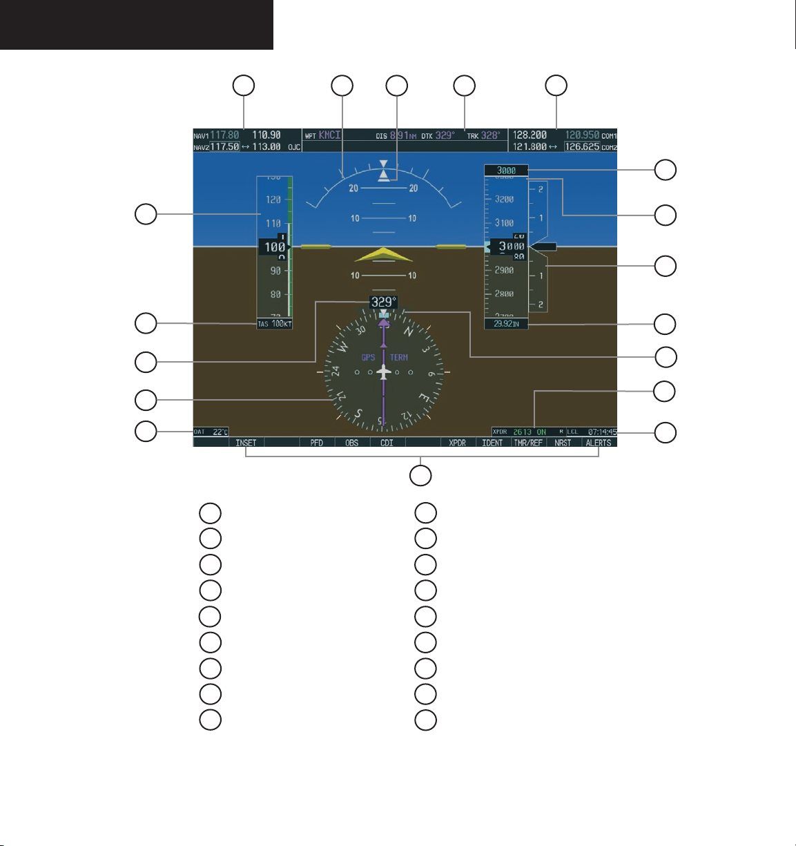
1
NAV Frequency Window
2
Airspeed Indicator
3
True Airspeed Box
4
Heading Box
5
Horizontal Situation Indicator
6
Outside Air Temperature Box
7
Softkeys
8
System Time Box
9
Transponder Status Bar
Figure 3.1.1 Default PFD Information
10
Turn Rate Indicator
11
Barometric Setting Box
12
Vertical Speed Indicator
13
Altimeter
14
Altitude Reference Box
15
COM Frequency Window
16
Navigation Status Bar
17
Slip/Skid Indicator
18
Attitude Indicator
190-00443-00 Rev. AGarmin G1000 PFD Pilot’s Guide for Mooney M20M & M20R3-2
Page 5
INTRODUCTION
10
1
9
8
2
3
4
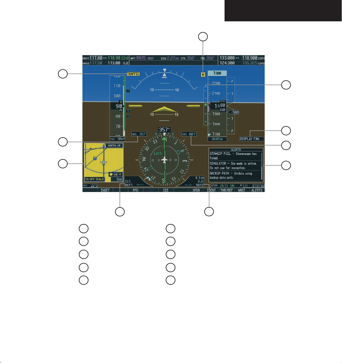
1
Traffic Annunciation
2
Selected Heading Box
3
Inset Map
4
BRG1 Information Window
5
BRG2 Information Window
Figure 3.1.2 Additional PFD Information
6
Alerts Window
7
Selected Course Box
8
Annunciation Window
9
Vertical Deviation/Glideslope Indicator
10
Marker Beacon Annunciation
5
7
6
190-00443-00 Rev. A Garmin G1000 PFD Pilot’s Guide for Mooney M20M & M20R
3-3
Page 6

INTRODUCTION
This page intentionally left blank.
190-00443-00 Rev. AGarmin G1000 PFD Pilot’s Guide for Mooney M20M & M20R3-4
Page 7
BACKLIGHTING
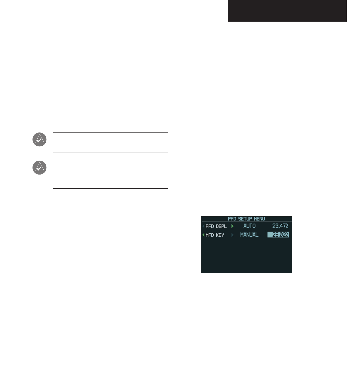
3.2 BACKLIGHTING
The backlighting of both the display and the keys can
be adjusted for the PFD and MFD. The backlighting in
tensity ranges from 0.14% to 100.00%. Two modes exist
for adjustment:
• Auto – The G1000 adjusts the backlighting automatically with reference to the amount of light in
the cockpit (default setting).
• Manual – Allows the pilot to manually adjust the
backlighting.
NOTE: Except in reversionary mode, the back-
lighting can only be adjusted from the PFD.
NOTE: No other window can be displayed in the
lower right corner of the PFD when the MENU
key is pressed to change the backlighting.
To manually adjust the backlighting for the
PFD and MFD:
-
To manually adjust the backlighting for the
PFD and MFD keys:
MENU
1. Press the
key on the PFD to display
the PFD Setup Menu window. ‘AUTO’ is now
highlighted next to PFD DSPL.
2. Turn the
DSPL’. Turn the
large FMS
knob to highlight ‘PFD
small FMS
knob in the direction
of the green arrow to display ‘PFD KEY’.
3. Turn the
Turn the
large FMS
small FMS
tion window. Turn the
‘MANUAL’, then press the
knob to highlight ‘AUTO’.
knob to display the selec-
FMS
knob to select
ENT
key.
4. With the intensity value now highlighted,
turn the
small FMS
backlighting, then press the
5. Turn the
large FMS
DSPL’ and turn the
knob to select the desired
ENT
key.
knob to highlight ‘MFD
small FMS
knob in the
direction of the green arrow to display ‘MFD
CLR
KEY’. Repeat steps 3 and 4. Press the
MENU
key to remove the window.
or
MENU
1. Press the
key on the PFD to display
the PFD Setup Menu window. ‘AUTO’ is now
highlighted next to ‘PFD DSPL’.
2. Turn the
small FMS
tion window. Turn the
‘MANUAL’, then press the
knob to display the selec-
FMS
knob to select
ENT
key.
3. With the intensity value now highlighted,
turn the
small FMS
backlighting, then press the
Turn the large FMS knob to highlight ‘AUTO’ next
4.
knob to select the desired
ENT
key.
Figure 3.2.1 PFD Setup Menu Window
to ‘MFD DSPL’, and repeat steps 2 and 3. Press
the
CLR
or
MENU
key to remove the window.
190-00443-00 Rev. A Garmin G1000 PFD Pilot’s Guide for Mooney M20M & M20R
3-5
Page 8

BACKLIGHTING
This page intentionally left blank.
3-6
190-00443-00 Rev. AGarmin G1000 PFD Pilot’s Guide for Mooney M20M & M20R
Page 9

SOFTKEYS
3.3 SOFTKEY FUNCTION
When a softkey is turned on, its color changes to black
text on gray background and remains this way until it is
turned off, at which time it changes to white text on black
background. The
ALERTS
gray background and automatically switch back to white
text on black background.
management functions including GPS, NAV, terrain, traf
fic and lightning.
softkeys change momentarily to black text on
Figure 3.3.1 Softkey On
The PFD softkeys listed provide control over flight
INSET – Press to display the Inset Map in the lower
left corner of the PFD.
OFF
DCLTR
desired amount of map detail. The declutter
level appears adjacent to the DCLTR softkey.
- No declutter: All map features are visible.
- Declutter – 1: Declutters land data.
- Declutter – 2: Declutters land and SUA data.
- Declutter – 3: Declutters large NAV data
remaining (removes everything except the
active flight plan).
TRAFFIC
TOPO
coastlines, terrain, rivers, lakes, etc.) and
elevation scale on the inset map.
TERRAIN
on the inset map.
LTNG
the inset map (within a 200 nm radius of the
aircraft).
BACK
softkey configuration.
CDI, IDENT, TMR/REF, NRST and
Figure 3.3.2 Softkey Off
-
– Press to remove the Inset Map.
(3) – Press momentarily to select the
– Press to display TIS traffic on the map.
– Press to display topographical data (i.e.,
– Press to display terrain information
– Press to display the lightning data on
– Press to return to the previous level
PFD – Press to display the additional softkeys for
additional configurations to the PFD.
METRIC
DFLTS
BRG1 (bearing)
360 HSI
ARC HSI
BRG2 (bearing)
STD BARO
BACK
– Press to display the current and reference altitudes in meters, in addition to feet.
Pressing the METRIC softkey also changes
the barometric setting to hectopascals.
– Press to reset default settings on the
PFD.
– Press to cycle through the fol-
lowing information:
NAV1
– Displays NAV1 waypoint frequency
or identifier and DME information in the
BRG1 information window.
GPS
– Displays GPS waypoint identifier and
DME information in the BRG1 information
window.
OFF
– Removes the BRG1 information
window.
– Press to display the 360° compass rose.
– Press to display the 140° viewable arcs.
– Press to cycle through the fol-
lowing information:
NAV2
– Displays NAV2 waypoint frequency
or identifier and DME information in the
BRG2 information window.
GPS
– Displays GPS waypoint identifier and
DME information in the BRG1 information
window.
OFF
– Removes the BRG2 information
window.
– Press to set the barometric pressure
to 29.92 inches of mercury (1013 hPa by
pressing the METRIC softkey).
– Press to return to the previous level
softkeys.
190-00443-00 Rev. A Garmin G1000 PFD Pilot’s Guide for Mooney M20M & M20R
3-7
Page 10

SOFTKEYS
CDI – Press to change navigation mode on the CDI
between GPS, NAV1 and NAV2.
OBS – Press to select OBS mode on the CDI when
navigating by GPS.
XPDR – Press to display the transponder mode selec-
tion softkeys.
STBY
– Press to select standby mode.
ON
– Press to select Mode A.
ALT
– Press to select altitude mode (Mode C).
VFR
– Press to automatically enter the VFR code
(1200 in the U.S.A. only).
CODE
– Press to display transponder code selection
softkeys 0-7.
0 through 7
IDENT
– Press numbers to enter code.
– Press to provide special aircraft
position identification to Air Traffic Control
(ATC).
BKSP
– Press to remove numbers entered one
at a time.
BACK
– Press to return to the previous level
softkeys.
IDENT
– Press to provide special aircraft position
identification to Air Traffic Control (ATC).
BACK
– Press to return to the previous level
softkeys.
IDENT – Press to provide special aircraft position
identification to Air Traffic Control (ATC).
TMR/REF – Press to display the Timer/References
window.
NRST – Press to display the Nearest Airports
window.
ALERTS – Press to display the Alerts window.
3-8
190-00443-00 Rev. AGarmin G1000 PFD Pilot’s Guide for Mooney M20M & M20R
Page 11
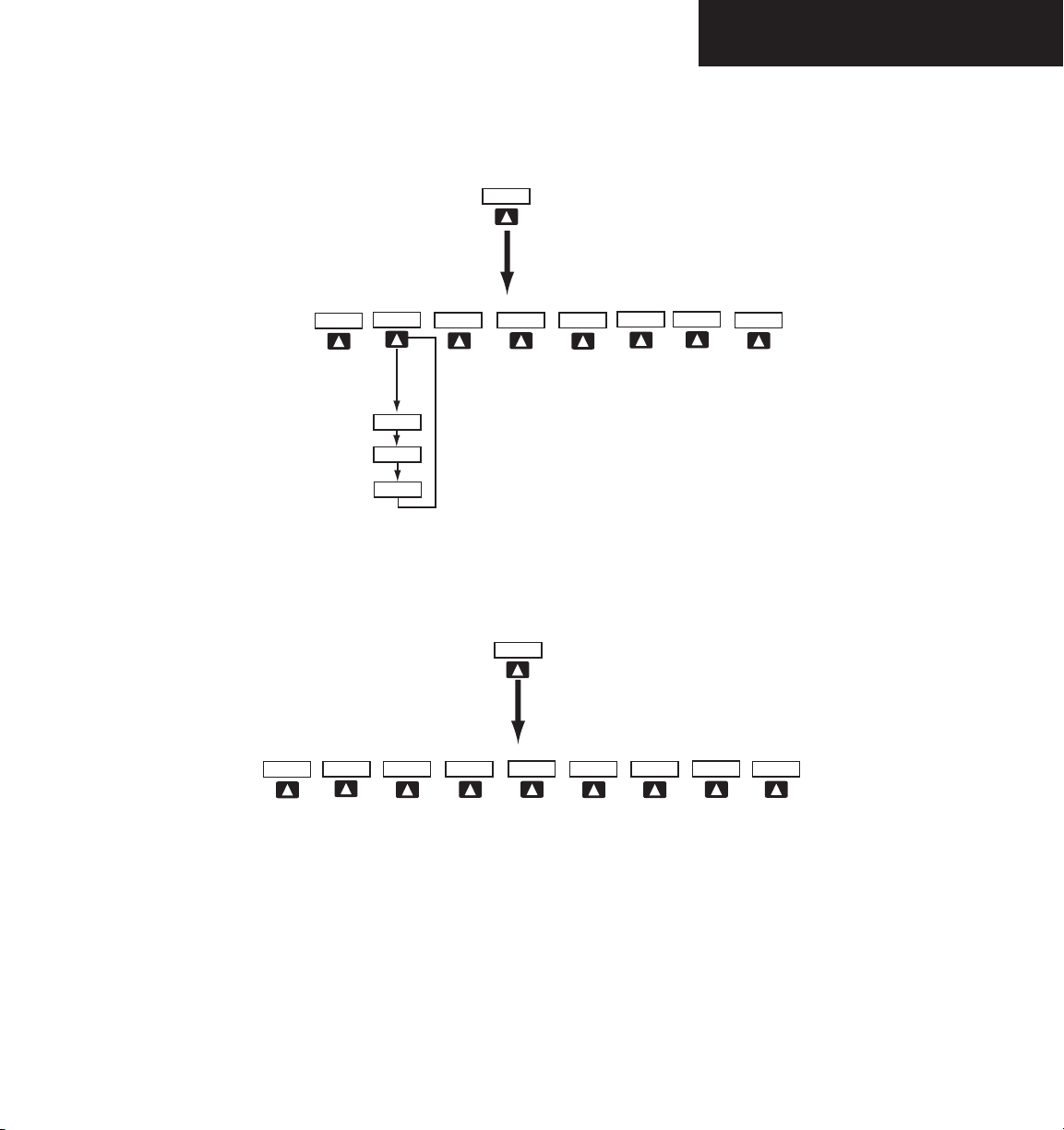
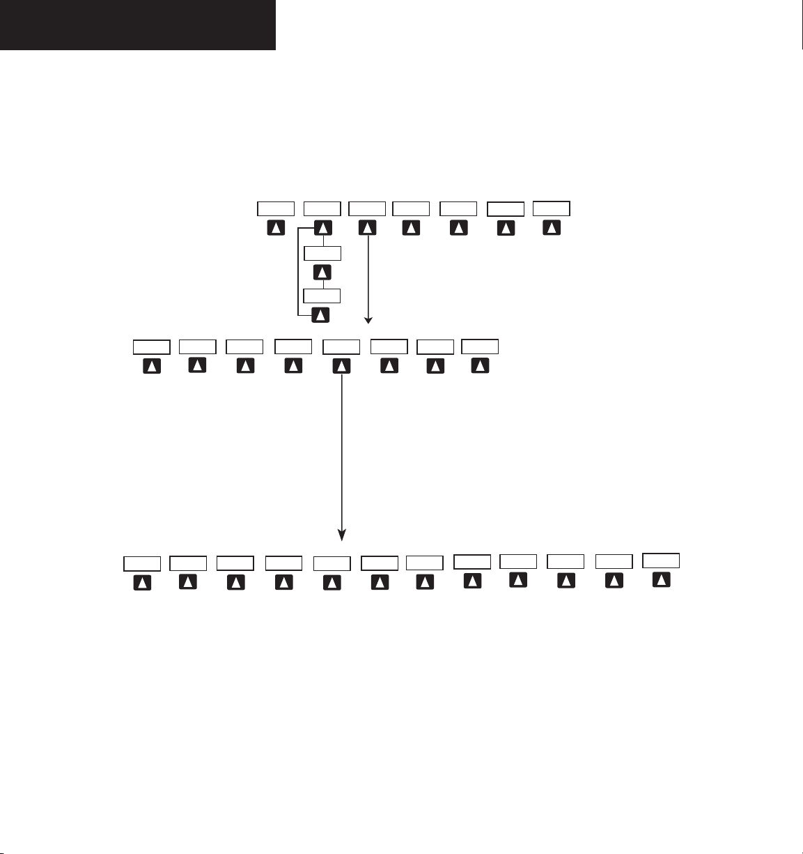
INSET
OFF
TOPO
TRAFFIC
TERRAIN
DCLTR
DCLTR-2
DCLTR-3
DCLTR-1
BACK
Press the BACK or OFF softkey
to return to the top level softkeys
ALERTS
LTNG
Figure 3.3.3 PFD Softkey Flow Chart – 1
PFD
METRIC
DFLTS
ARC HSI
360 HSI
Press the STD BARO or BACK softkeys
to return to the top level softkeys
Press the DFLTS softkey to change the PFD
metric values to standard
STD BARO
BACK
ALERTS
BRG2
BRG1
SOFTKEYS
Figure 3.3.4 PFD Softkey Flow Chart – 2
190-00443-00 Rev. A Garmin G1000 PFD Pilot’s Guide for Mooney M20M & M20R
3-9
Page 12
SOFTKEYS
NRST
OBS
TMR/REF
IDENT
ALERTS
XPDR
STBY
ON
BACK
VFR
ALT
CODE
IDENT
0
1
6
3
2
4
5
7
IDENT
BACK
BKSP
Press the BACK softkey
to return to the top level
softkeys
Press the IDENT
softkey to return to
the top level softkeys
ALERTS
ALERTS
CDI
CDI (NAV1)
CDI (NAV2)
3-10
Figure 3.3.5 PFD Softkey Flow Chart – 3
190-00443-00 Rev. AGarmin G1000 PFD Pilot’s Guide for Mooney M20M & M20R
Page 13

FLIGHT INSTRUMENTS
3.4 FLIGHT INSTRUMENTS
AIRSPEED INDICATOR
The Airspeed indicator displays airspeed on a rolling
number gauge using a moving tape. The following infor
mation is also displayed:
• Speed indication
• Speed ranges
• Airspeed trend vector
• Vspeed references
Speed Indication
The numeric labels and major tick marks on the moving tape are marked at intervals of 10 knots, while minor
tick marks on the moving tape are indicated at intervals
of 5 knots. Speed indication starts at 20 knots, with 60
knots of airspeed viewable at one time. The actual air
speed is displayed inside the black pointer. The pointer
remains black until reaching never exceed speed (Vne), at
which point it turns red.
-
-
Vspeed References
Vspeeds are set using the TMR/REF softkey. Vr, Vx, Vy
and Glide are shown on the References window. When
active (ON), the Vspeeds are displayed at their respective
locations to the right of the airspeed scale (refer to the
Auxiliary windows section in this Pilot’s Guide to set and
display Vspeeds).
True Airspeed Box
The True Airspeed box is located below the Airspeed
indicator and displays the true airspeed in knots.
Airspeed Trend
Vector
Vspeed
References
Actual Airspeed
Speed Ranges
Speed Ranges
A color-coded (white, green, yellow, and red) speed
range strip is located on the moving tape. The colors de
note flaps operating range, normal operating range, cau
-
tion range, and never exceed speed (Vne). A red range is
also present for low speed awareness. Refer to the Aircraft
Flight Manual Supplement (AFMS) for speed criteria.
True Airspeed
Box
Figure 3.4.1 Airspeed Indicator
Airspeed Trend Vector
The vertical, magenta line extends up or down on the
airspeed scale located right of the color-coded speed range
strip. The end of the trend vector displays approximately
what airspeed will be reached in 6 seconds if the current
rate of acceleration is maintained. The trend vector is ab
sent if the speed remains constant and if any data needed to
calculate airspeed is not available due to a system failure.
190-00443-00 Rev. A Garmin G1000 PFD Pilot’s Guide for Mooney M20M & M20R
Figure 3.4.2 Red Pointer at Vne
3-11
Page 14
FLIGHT INSTRUMENTS
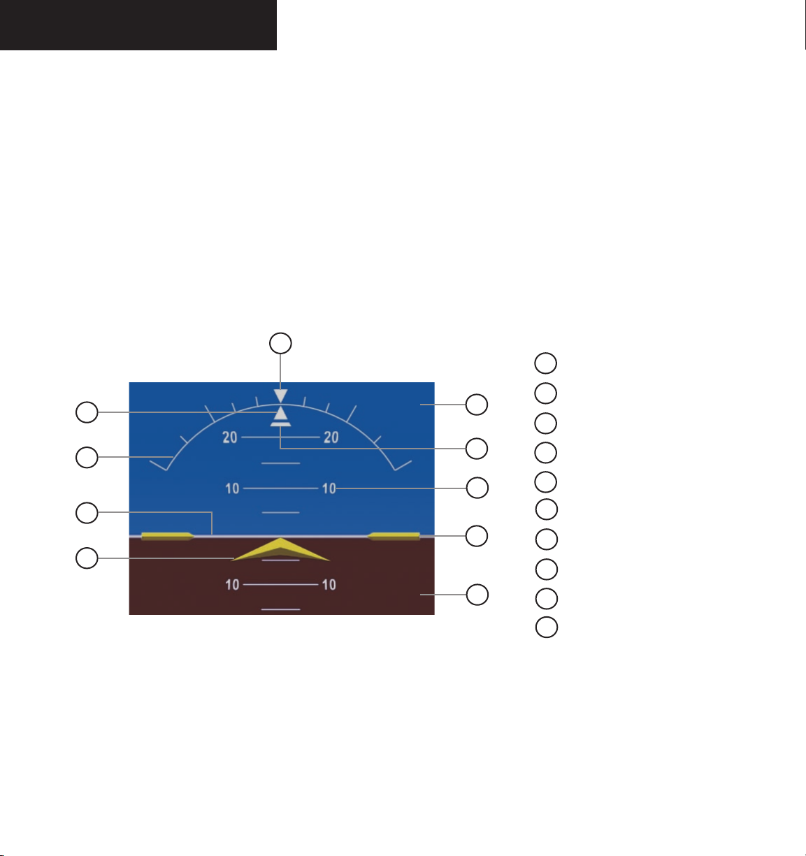
ATTITUDE INDICATOR
The attitude information is displayed over a virtual
blue sky and brown ground with a white horizon line.
The aircraft wing tips are represented by two yellow bars
on the horizon line. The yellow inverted “V” represents
the aircraft. The Attitude indicator displays the following
information:
• Pitch indication
• Roll indication
• Slip/Skid indication
10
1
2
3
4
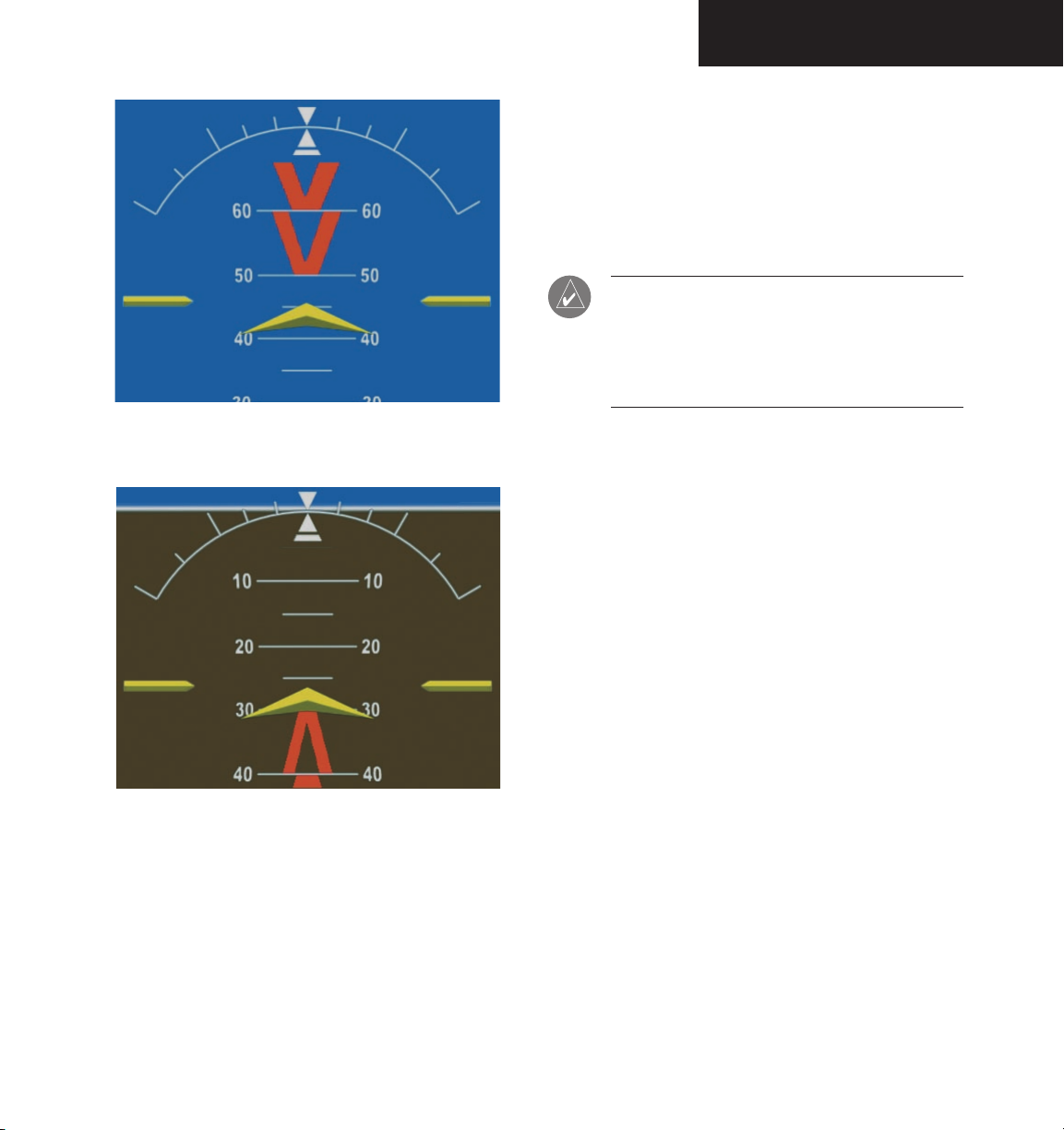
Pitch Indication
Major pitch marks and numeric labels at 10, 20, 30,
40, 50, 60, 70 and 80 degrees are shown above and below the horizon line. Minor pitch marks at 5, 15 and 25
degrees above the horizon line and 5, 15, 25, 35 and 45
degrees below the horizon line are shown. The horizon
line is part of the pitch scale. Red extreme pitch warning
chevrons pointing toward the horizon are displayed starting at 50 degrees above and 30 degrees below the horizon
line (refer to the figures on the next page).
1
Roll Pointer
2
9
8
7
6
Roll Scale
3
Horizon Line
4
Aircraft Symbol
5
Land Representation
6
Aircraft Wing Tips
7
Pitch Scale
8
Slip/Skid Indicator
3-12
Figure 3.4.3 Attitude Indicator
5
9
Sky Representation
10
Roll Index
190-00443-00 Rev. AGarmin G1000 PFD Pilot’s Guide for Mooney M20M & M20R
Page 15
FLIGHT INSTRUMENTS
Roll Indication
Major tick marks at 30 and 60 degrees and minor tick
marks at 10, 20 and 45 degrees are shown to the left and
right on the roll scale. The inverted white triangle indicates 0 on the roll scale. Angle of bank is indicated by the
position of the roll pointer on the roll scale.
NOTE: Supplemental flight data such as the Inset
Map, Alerts and Annunciation window disappear
from the PFD when pitch is greater than +30˚
and less than -20˚ or when a 65˚ bank angle is
reached.
Figure 3.4.4 Attitude Indicator Nose High
Figure 3.4.5 Attitude Indicator Nose Low
Slip/Skid Indication
The Slip/Skid indicator resides beneath the roll pointer.
The indicator moves with the roll pointer and moves laterally away from the pointer to indicate lateral acceleration. A
slip/skid is indicated by the location of the Slip/Skid indicator relative to the roll pointer. One Slip/Skid indicator displacement is equal to one ball displacement on a traditional
Slip/Skid indicator.
190-00443-00 Rev. A Garmin G1000 PFD Pilot’s Guide for Mooney M20M & M20R
3-13
Page 16
FLIGHT INSTRUMENTS
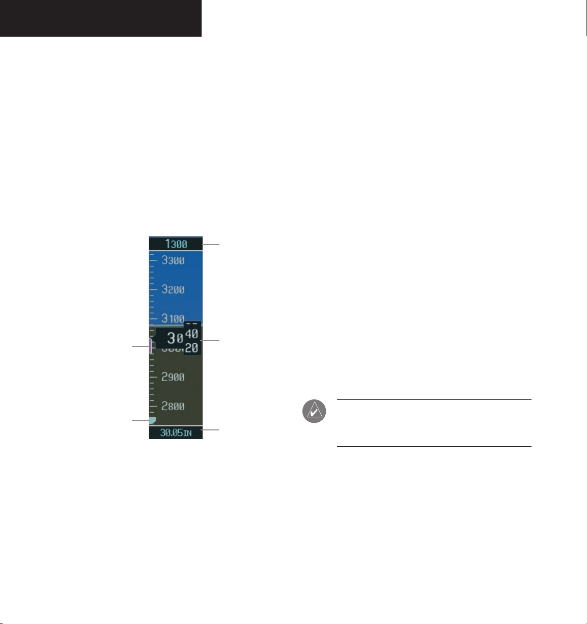
ALTIMETER
The Altimeter displays barometric altitude values in
feet on a rolling number gauge using a moving tape. The
Altimeter displays the following information:
• Altitude values
• Altitude reference bug
• Altitude trend vector
• Altitude reference box
• Barometric setting box
• Altitude alerter
• Metric display
Altitude Reference
Box
Altitude Trend
Vector
Current Altitude
Altitude Reference Bug
The Altitude Reference Bug is displayed at the reference
altitude or the edge of the tape (whichever is closer to the
current altitude) to provide increased altitude awareness.
To set the altitude reference bug:
ALT
1. Turn the
bug. The
the
large ALT
knobs to set the altitude reference
small ALT
knob sets the hundreds and
knob sets the thousands. This
altitude also appears in the altitude reference
box above the altimeter.
Altitude Trend Vector
The vertical magenta line extends up or down the altitude scale located left of the numeric labels. The end
of the trend vector displays approximately what altitude
will be reached in 6 seconds if the current rate of vertical
speed is maintained. The trend vector is absent if altitude
remains constant, or if any data needed to calculate it is
not available due to a system failure.
Altitude Reference Box
The Altitude Reference box displays the reference altitude in feet. The metric value, when selected, is displayed
on top of the Altitude Reference box.
3-14
Altitude Reference Bug
Figure 3.4.6 Altimeter
Barometric Setting
Box
Altitude Values
The numeric labels and major tick marks are shown
at intervals of 100 feet. Minor tick marks are at intervals
of 20 feet. The current altitude is displayed in the black
pointer.
NOTE: The Altitude Reference box is not part of
the autopilot altitude preselect system and is
used to aid the pilot in altitude control.
Barometric Setting Box
The Barometric Setting Box displays the barometric pres-
sure in inches of mercury (in Hg) or hectopascals (hPa).
To select barometric pressure:
1. Turn the large BARO (outer) knob to select
the desired setting.
190-00443-00 Rev. AGarmin G1000 PFD Pilot’s Guide for Mooney M20M & M20R
Page 17

Altitude Alerting
The altitude alerter provides the pilot with a visual alert
when approaching the reference altitude. Although flight
control systems use the same reference altitude box as the
altitude alerter does, the altitude alerter is not coupled to
a flight control system and can function without one. The
visual annunciations appear in the altitude reference box.
Anytime the reference altitude is changed, the altitude
alerter is reset.
FLIGHT INSTRUMENTS
There is an altitude band set at +/- 1,000 ft of the refer
ence altitude and a deviation band set at +/- 200 ft of the
reference altitude. When the pilot climbs or descends to
the reference altitude, the reference altitude flashes with
cyan text on a black background for 5 seconds, then it
changes to black text on a cyan background as the aircraft
passes through +/- 1,000 ft of the reference altitude.
When the aircraft passes within +/- 200 ft of the refer
ence altitude, the reference altitude flashes with cyan text
on a black background, indicating that the aircraft is within the deviation band. Each time the pilot flies outside
the deviation band (+/- 200 ft of the reference altitude),
the reference altitude flashes with yellow text on a black
background for 5 seconds.
Figure 3.4.8 Altimeter within 1,000 ft of Reference Altitude
Figure 3.4.7 Colors Associated with the Altitude Alerter
Figure 3.4.9 Altimeter within 200 ft of Reference Altitude
190-00443-00 Rev. A Garmin G1000 PFD Pilot’s Guide for Mooney M20M & M20R
3-15
Page 18

FLIGHT INSTRUMENTS
Metric Display
Reference and current altitude can be displayed in meters. The barometric pressure may also be displayed in
hectopascals.
To display altitude in meters and barometric
pressure in hectopascals:
1. Press the
level softkeys.
2. Press the METRIC softkey to display altitude in
meters and barometric pressure in hectopascals.
Press the
softkeys.
PFD softkey to display the second
BACK
softkey to return to the top level
Vertical Deviation/Glideslope Indicator
The Vertical Deviation/Glideslope Indicator is a window on the left side of the Altimeter. The window appears
when an ILS is tuned in the active NAV field (and selected
on the audio panel). A green diamond appears and acts
as the vertical deviation indication, just like a glideslope
needle on a conventional indicator.
Marker Beacon Annunciations
Marker Beacon Annunciations are displayed on the
PFD to the left of the Altitude Reference Box. Outer marker reception is indicated by a blue light. Middle marker
reception is indicated by an amber light. Inner marker
reception is indicated by a white light (refer to the Audio
Panel Pilot’s Guide for more information).
Marker Beacon
Annunciation
3-16
Figure 3.4.10 Altimeter (Metric)
Vertical
Deviation/Glideslope
Indicator
Figure 3.4.11 Marker Beacon and Vertical Deviation
190-00443-00 Rev. AGarmin G1000 PFD Pilot’s Guide for Mooney M20M & M20R
Page 19

VERTICAL SPEED INDICATOR
The Vertical Speed Indicator displays the aircraft vertical speed with numeric labels and tick marks at 1,000 ft
and 2,000 ft in each direction on the non-moving tape.
Minor tick marks are at intervals of 500 ft.
FLIGHT INSTRUMENTS
Vertical Speed Pointer
The Vertical Speed Pointer displays the current vertical
speed and points to that speed on the non-moving tape. If
the rate of ascent is greater than 2,000 feet per minute, the
pointer appears at the top edge of the non-moving tape and
the number of feet per minute appears inside the pointer. If
the rate of descent is greater than 2,000 feet per minute, a
negative sign is displayed in the pointer (-2,000) for negative (down) vertical speed and the pointer appears at the
bottom edge of the non-moving tape.
NOTE: Digits appear in the pointer when the
climb or descent rate is greater than 100 fpm.
Vertical Speed
Pointer
Figure 3.4.12 Vertical Speed Indicator
190-00443-00 Rev. A Garmin G1000 PFD Pilot’s Guide for Mooney M20M & M20R
3-17
Page 20

FLIGHT INSTRUMENTS
HORIZONTAL SITUATION INDICATOR
The Horizontal Situation Indicator (HSI) displays a
rotating compass card with letters at the cardinal points
and numeric labels every 30 degrees. Major tick marks
are at 10 degree intervals and minor tick marks are at 5
degree intervals. The HSI is displayed in a heading-up
orientation. The HSI compass can be displayed as a 360°
rose or a 140° arc by pressing the PFD softkey, followed by
the 360 HSI or the ARC HSI softkey. The HSI displays the
following information:
• Heading indication
• Turn Rate indicator
• Course Deviation Indicator
• Bearing pointers (360˚ HSI only)
• Bearing information windows (360˚ HSI only)
• Navigation source
360˚ HSI
The 360˚ HSI contains a course deviation indicator
(CDI), with a course pointer arrow, a TO/FROM arrow,
a sliding deviation bar and scale. The course pointer is a
single line arrow (GPS, VOR1 and LOC1) or double line
arrow (VOR2 and LOC2) which points in the direction
of the set course. The TO/FROM arrow rotates with the
course pointer and is displayed when the active NAVAID
is received.
14
13
1
2
3
4
5
6
1
Turn Rate Indicator
2
Lateral Deviation Scale
3
Navigation Source
4
Aircraft Symbol
5
Course Deviation Indicator
6
Rotating Compass Rose
7
OBS Mode
8
TO/FROM Indicator
9
Heading Bug
10
Course Pointer
11
Flight Phase
12
Turn Rate and Heading Trend Vector
13
Heading
14
Lubber Line
12
11
10
9
8
7
3-18
Figure 3.4.13 Horizontal Situation Indicator
190-00443-00 Rev. AGarmin G1000 PFD Pilot’s Guide for Mooney M20M & M20R
Page 21

FLIGHT INSTRUMENTS
ARC HSI
The Arc HSI is a 140˚ expanded section of the compass rose. The Arc contains a course pointer arrow, a TO/
FROM indicator, a sliding deviation indicator (the TO/
FROM and sliding deviation indicators are one and the
same), and deviation scale. Upon station passage, the TO/
FROM indicator flips and points to the tail of the aircraft
just like the conventional TO/FROM flag. Depending on
the source of navigation, the CDI on the Arc HSI can appear in the following ways:
• GPS, OBS, VOR – appears as a arrowhead
• Localizer – appears as a diamond
NOTE: If the pilot makes a heading change
˚
greater than 105
CDI switches to the opposite side of the deviation
scale and displays reverse sensing.
with respect to the course, the
Heading Indication
A digital reading of the current magnetic heading appears on top of the HSI. A rotatable heading bug on the
compass rose and arc marks the desired heading. When
the pilot selects a heading, a digital reading appears for 3
seconds in a box left of the lubber line, next to the HSI.
Figure 3.4.15 Selected Heading Box
When the pilot selects a course, a digital reading appears for 3 seconds in a box right of the lubber line, next
to the HSI.
Figure 3.4.16 Selected Course Box
NOTE: The heading displayed on the HSI is always
Lateral Deviation
Scale
NOTE: When the Arc HSI is displayed, the BRG1
and BRG2 information windows are disabled.
190-00443-00 Rev. A Garmin G1000 PFD Pilot’s Guide for Mooney M20M & M20R
Course Deviation and
TO/FROM Indicator
Figure 3.4.14 ARC HSI
magnetic, even if the NAV ANGLE is set to ‘TRUE’
in the AUX System Setup Page on the MFD.
3-19
Page 22

FLIGHT INSTRUMENTS
Turn Rate Indicator
The Turn Rate Indicator resides directly above the rotating compass card. Each tick mark is at 9 (half standard
rate) and 18 (standard rate) degrees to the left and right of
the lubber line. A wide magenta line displays the current
turn rate up to 24 degrees. A magenta arrowhead appears
at 25 degrees and disappears at 24 degrees. This trend
vector provides the pilot with a six-second prediction of
what heading will be reached given the present turn rate.
Figure 3.4.17 Turn Rate Indicator and Trend Vector
Course Deviation Indicator
The Course Deviation Indicator (CDI) moves left or
right from the course pointer along a deviation scale to
display aircraft position relative to the course.
The CDI has the same angular limits as a mechanical CDI when coupled to a VOR or LOC. When coupled
to GPS, the full scale limits for the CDI are defined by a
GPS-derived distance (5.0, 1.0 or 0.3 nm). The CDI scale
automatically adjusts to the desired limits based upon the
current phase of flight (enroute 5.0 nm, terminal area 1.0
nm, or approach 0.3 nm). The desired GPS scale settings
may be selected manually from the MFD (refer to the Multi
Function Display Pilot’s Guide).
3-20
Figure 3.4.18 Arc CDI and Compass Rose CDI
190-00443-00 Rev. AGarmin G1000 PFD Pilot’s Guide for Mooney M20M & M20R
Page 23

FLIGHT INSTRUMENTS
Bearing Pointers and Information Windows
There are two bearing pointers available, one or two
can be displayed on the HSI. Pressing the PFD softkey
provides access to the BRG1 and BRG2 softkeys. BRG1
pointer is a single cyan (light blue) line with an open arrowhead at the end. BRG2 pointer is a double cyan (light
blue) line with an open arrowhead at the end. The bearing pointers never override the CDI. When one or more
bearing pointers are displayed (but not necessarily visible
if there is no data available), a white ring is presented
around the center of the compass rose to visually separate
the bearing pointer(s) from the CDI.
When a bearing pointer is displayed its associated
information window is also displayed. BRG1 information window is displayed to the lower left of the HSI
and includes the bearing source (NAV1), a pointer icon,
frequency and distance (NAV1 and GPS) to the bearing
source. BRG2 information window is displayed to the
lower right of the HSI and includes the bearing source
(NAV2), a pointer icon, frequency and distance (NAV2) to
the bearing source.
If GPS is the bearing source, the active waypoint identifier is displayed in lieu of a frequency. If an active waypoint is not selected, the bearing pointer is removed from
the HSI and “NO DATA” is displayed in the information
window.
If the NAV radio is the bearing source and is tuned to
an ILS frequency, the bearing pointer is removed from the
HSI and the frequency is replaced with “ILS”. If the NAV
radio is not receiving the tuned VOR station, the bearing
pointer is removed from the HSI and the frequency displayed in the information window is replaced with “NO
DATA”.
When NAV1 or NAV2 is the selected bearing source,
the frequency is replaced by the station identifier when
the station is in range.
Bearing 2
Pointer
Bearing 1
Information
Window
Figure 3.4.19 HSI with Bearing Information
Distance to
Bearing Source
Waypoint
Identifier
Bearing
Source
Figure 3.4.20 BRG1 Information Window
Pointer
Icon
Figure 3.4.21 BRG2 Information Window
Bearing 1
Pointer
Bearing 2
Information
Window
Pointer
Icon
Distance to
Bearing Source
Bearing
Source
Waypoint
Identifier
190-00443-00 Rev. A Garmin G1000 PFD Pilot’s Guide for Mooney M20M & M20R
3-21
Page 24

FLIGHT INSTRUMENTS
Navigation Source
The HSI can display two sources of navigation, GPS
or NAV (VOR, localizer, and glideslope). In GPS mode
the flight plan legs are sequenced automatically. Enabling
OBS mode suspends auto sequencing of waypoints, but
retains the current “active-to” waypoint as the navigation
reference even after passing the waypoint. When OBS is
disabled, the GPS returns to normal operation, with au
tomatic sequencing of waypoints. OBS mode also allows
the pilot to set the desired course TO/FROM a waypoint.
Color indicates the current navigation source, magen
ta (for GPS ) or green (for VOR and LOC). As the user
crosses the MAP, “SUSP” appears on the HSI in place of
OBS and the
OBS softkey now reads “SUSP”, indicating
that automatic sequencing of approach waypoints is suspended at the MAP. A yellow ‘INTEG’ and ‘WARN’ may
appear on the HSI when the following occurs:
• INTEG – RAIM is not available
• WARN – GPS detects a position error
To change between navigation sources:
-
-
To enable/disable OBS mode while navigating
with GPS
1. Press the
:
OBS softkey to select OBS Mode.
2. Turn the small CRS knob to select the desired
course TO/FROM the waypoint.
3. Press the OBS softkey again to return to normal
operation.
3-22
1. Press the
CDI softkey to change from GPS to
VOR1 or LOC1. This places the cyan tuning box
over the NAV1 standby frequency in the upper
left corner of the PFD.
2. Press the
CDI softkey again to change from
VOR1 or LOC1 to VOR2 or LOC2. This places
the cyan tuning box over the NAV2 standby
frequency.
CDI
3. Press the
softkey a third time to return to
GPS.
Figure 3.4.22 GPS INTEG, GPS SUSP, NAV1 and NAV2
190-00443-00 Rev. AGarmin G1000 PFD Pilot’s Guide for Mooney M20M & M20R
Page 25

3.5 COMMUNICATION,
NAVIGATION & SURVEILLANCE
COMMUNICATION FREQUENCY WINDOW
CNS
The Communication Frequency window provides the
control and display of dual VHF Radio Communication
Transceivers (COM1 and COM2). The Communication
Frequency window displays the following information:
• COM1 and COM2 active and standby frequencies
• Color-coded indication of the active COM transceiver
NOTE: Operating procedures for the Communica-
tion Frequency window are located in the VHF
NAV/COM Pilot’s Guide.
NAVIGATION FREQUENCY WINDOW
The Navigation Frequency window provides the control and display of dual VOR/ILS receivers (NAV1 and
NAV2). The Navigation Frequency window displays the
following information:
• NAV1 and NAV2 active and standby frequencies
• NAV1 and NAV2 identifier, if the active NAV1 or
NAV2 frequency is a valid, identified frequency
• Color-coded indication of the active NAV receiver
Selected COM
Radio
(Green)
Figure 3.5.1 Communication Frequency Window
NAV Receivers
Active COM
Frequency Field
Frequency
Toggle Arrow
Frequency
Tuning Box
Standby NAV
Frequency Field
Frequency
Tuning Box
COM Radios
Standby COM
Frequency Field
Active NAV
Frequency Field
Selected NAV
Radio
(Green)
Frequency
Toggle Arrow
Figure 3.5.2 Navigation Frequency Window
NOTE: Operating procedures for the Navigation Fre-
quency window are located in the VHF NAV/COM
Pilot’s Guide.
190-00443-00 Rev. A Garmin G1000 PFD Pilot’s Guide for Mooney M20M & M20R
3-23
Page 26

CNS
NAVIGATION STATUS BAR
The Navigation Status bar resides at the top of the PFD
and displays valuable information while flying a route.
The following information is displayed:
• The next waypoint in the active flight plan
• Distance to the next waypoint (DIS)
• Desired track to the next waypoint (DTK)
• Current track angle (TRK)
• GPS Navigation Annunciations
NOTE: The fields in the PFD Navigation Status
bar cannot be changed.
Distance to
Next Waypoint
Next Waypoint
Desired Track
To
Next Waypoint
Current Track
3-24
Figure 3.5.3 Navigation Status Bars
Figure 3.5.4 Navigation Status Bar Message
190-00443-00 Rev. AGarmin G1000 PFD Pilot’s Guide for Mooney M20M & M20R
Page 27

CNS
TRANSPONDER STATUS BAR
The Transponder Status bar displays the transponder
code, reply symbol, and mode of operation. TIS (Traffic
Information System) surveillance data up-linked by Air
Traffic Control (ATC) radar through the GTX33
S Transponder appears on the Inset Map (PFD), Navi
gation and Traffic Map Pages on the MFD (refer to the
Multi Function Display Pilot’s Guide). If the transponder
is configured with Automated Airborne Determination,
normal operation begins when lift-off is sensed. When
the aircraft is on the ground, the window automatically
displays “GND”. The transponder does not respond to AT
CRBS interrogations when GND is annunciated. If a delay
time is set in Configuration Mode, the transponder waits
a specified length of time after landing before changing to
GND mode.
Transponder Operation
Pressing the XPDR softkey displays the second-level
softkeys:
• STBY – Selects standby mode. When in standby
mode, the transponder does not reply to any
interrogations.
• ON – Selects Mode A. In this mode, the transponder replies to interrogations, as indicated by the
Reply Symbol (R). Replies do not include altitude
information.
• ALT – Selects Mode C. In ALT mode, the tran-
sponder replies to identification and altitude
interrogations, as indicated by the Reply Symbol
(R). Replies to altitude interrogations include the
standard pressure altitude received from an external
altitude source (not adjusted for barometric pres
sure). The ALT mode may be selected in aircraft
not equipped with an optional altitude encoder;
however, in this case, the reply signal only replies
to mode A interrogations. The transponder also
responds to interrogations from TCAS-equipped
aircraft.
Mode
-
-
-
• VFR – Sets the transponder code to the pre-programmed VFR code selected in Configuration
Mode (this is set to 1200 at the factory in the
U.S.A. only; please refer to ICAO standards for
VFR codes in other countries).
• CODE – Displays the transponder code selection
softkeys, which includes the digits 0-7 and BKSP.
• IDENT – Pressing the IDENT softkey activates
the Special Position Identification (SPI) Pulse for
18 seconds, identifying the transponder return on
the ATC screen.
Transponder Code Selection
Transponder code selection is performed with eight
softkeys (0-7) providing 4,096 active identification codes.
Pushing one of these softkeys begins the code selection
sequence. The new code is activated five seconds after the
fourth digit is entered. Pressing the
one digit at a time until the status bar is empty (refer to the
Mode S Transponder Pilot’s Guide).
Figure 3.5.5 Transponder Status Bar
BKSP softkey removes
190-00443-00 Rev. A Garmin G1000 PFD Pilot’s Guide for Mooney M20M & M20R
3-25
Page 28

CNS
This page intentionally left blank.
3-26
190-00443-00 Rev. AGarmin G1000 PFD Pilot’s Guide for Mooney M20M & M20R
Page 29

SUPPLEMENTAL FLIGHT DATA
3.6 SUPPLEMENTAL FLIGHT DATA
OUTSIDE AIR TEMPERATURE BOX
The outside air temperature (OAT) is displayed in °C.
On the AUX System Setup Page of the MFD OAT can be
configured to display °F instead of °C (refer to the Multi
Function Display Pilot’s Guide).
Figure 3.6.1 Outside Air Temperature Box
SYSTEM TIME BOX
The System Time Box displays the local time. Time and
date is obtained from the satellites and cannot be changed.
The pilot may select the desired time format and offset.
There are 3 time formats available: Local 12 hr, Local 24 hr
and Coordinated Universal Time (UTC). The Time Offset
(Time Zone) represents the number of hours plus or minus
UTC (refer to the Multi Function Display Pilot’s Guide).
TRAFFIC ANNUNCIATION
The G1000 system displays Traffic Information Service
(TIS) traffic on the Inset Map (PFD) and the Navigation
Map Page (MFD). When a traffic advisory is detected, the
following automatically occurs:
• The Inset Map is enabled and displays the traffic.
• A single “TRAFFIC” voice message is heard.
• A flashing “TRAFFIC” annunciation appears to the
top left of the Attitude indicator. This alert flashes
(black text on yellow background) for 5 seconds
and remains displayed until no TAs are detected
in the area.
NOTE: If a second TA appears or if the TAs
displayed decrease and then increase, a new
audio alert is heard and a new visual alert is
displayed.
NOTE: Refer to the Appendix for detailed infor-
mation on the Traffic Information Service (TIS).
Figure 3.6.3 Traffic Annunciation
Figure 3.6.2 System Time Box
190-00443-00 Rev. A Garmin G1000 PFD Pilot’s Guide for Mooney M20M & M20R
3-27
Page 30

SUPPLEMENTAL FLIGHT DATA
INSET MAP
The following Inset Map operations can be performed
and are independent of the MFD:
The Inset Map is a smaller version of the Navigation
Map Page on the MFD. It appears in the lower left corner
of the PFD and is displayed by pressing the
INSET softkey. The map disappears from the PFD anytime pitch is
greater than +30° and less than –20°, or when a 65° bank
angle is reached. The direct-to function is not available
from the Inset Map. The fuel reserve rings are enabled
and disabled from the MFD only. The Inset Map displays
• Change the zoom range
• Change the declutter level
• Enable/disable traffic data
• Enable/disable topo data
• Enable/disable terrain data
• Enable/disable lightning data (optional)
• Pan Map
the following information:
NOTE: The map orientation is always the same as
that for the Navigation Map Page on the MFD.
• Moving map with orientation references
– North Up
– Track Up
– DTK Up
– HDG Up
• Zoom range legend
• Declutter levels (3)
• Aircraft icon
• Traffic data
• Topo data
• Terrain data
• Lightning data (optional)
• Enabled map features
• Active navigation route
• Track vector
• Fuel ring (reserve)
1
2
3
4
Wind Vector
1
2
NAV Compass Range
NAV Compass
3
Traffic Icon and Scale
4
5
Map Range
Terrain Icon
6
7
Active Navigation Route
Track Vector
8
9
8
7
6
5
3-28
NOTE: Map orientation and other map features
are enabled on the MFD (refer to the Multi Func
tion Display Pilot’s Guide).
NOTE: Refer to the Multi Function Display Pilot’s
Guide for a detailed explanation of the declutter
levels.
9
Map Orientation
-
Figure 3.6.4 Inset Map
190-00443-00 Rev. AGarmin G1000 PFD Pilot’s Guide for Mooney M20M & M20R
Page 31

To change the zoom range:
1. Turn the
joystick
clockwise to increase or
counterclockwise to decrease the range. Zoom
ranges from 500 feet to 2,000 nautical miles.
To change the declutter level:
1. Press the
softkey. Press the
DCLTR
soft-
INSET
key to remove background map details until
the desired amount of detail is depicted. The
declutter level appears above the softkey (i.e.,
DCLTR-1). Refer to the Multi Function Display
Pilot’s Guide for more details.
To enable/disable traffic data:
1. Press the
softkey. Press the
TRAFFIC
INSET
softkey to display Traffic Information Service
(TIS) traffic. Traffic symbology appears next to
the aircraft icon and in the bottom right corner
of the map.
2. Press the
TRAFFIC
softkey again to remove data
from the map.
NOTE: TIS displays traffic within seven nautical
miles from 3,000 ft below to 3,500 ft above the
requesting aircraft, and includes location, direc
tion, altitude, and climb/descent information.
-
When a traffic advisory is detected the following auto-
matically occurs:
• The Inset Map is enabled and displays the traffic.
• A single “TRAFFIC” voice message sounds.
• A flashing “TRAFFIC” annunciation appears to the
top left of the Attitude Indicator. This alert flashes
(black text on yellow background) for 5 seconds
and remains displayed until no TAs are detected
in the area.
SUPPLEMENTAL FLIGHT DATA
NOTE: Refer to the Appendix for more details
about Traffic Information Service (TIS).
To enable/disable topo data:
1. Press the
softkey. Press the
TOPO
INSET
key to display topographic land colors, which
represent land elevation.
TOPO
2. Press the
softkey again to remove topo
data from the map.
NOTE: When topo data is removed from the
display, all cartographic data is automatically
removed and the Jeppesen Nav Data is presented
on a black background.
To enable/disable terrain data:
INSET
1. Press the
softkey. Press the
softkey to display color-coded terrain tiles, which
are based upon the aircraft current altitude. A
mountain icon appears above the zoom range
in the lower right corner of the map, showing
that terrain is selected.
• Red (warning) – Land elevation is within 100
ft or above the aircraft current altitude.
• Yellow (caution) – Land elevation is greater
than 100 ft to 1,000 ft below aircraft altitude.
• Black – Land elevation greater than 1,000 ft
below aircraft altitude.
2. Press the
TERRAIN
softkey again to remove the
terrain data from the map.
NOTE: Terrain data is not displayed when the
aircraft latitude is greater than 75˚ North or 60˚
South.
soft-
TERRAIN
NOTE: If a second TA appears or if the TAs dis-
played decrease and then increase, a new audio
is heard and an alert is displayed.
190-00443-00 Rev. A Garmin G1000 PFD Pilot’s Guide for Mooney M20M & M20R
NOTE: Refer to the Appendix for more details
about terrain.
3-29
Page 32

SUPPLEMENTAL FLIGHT DATA
To enable/disable lightning data (optional):
INSET
1. Press the
softkey. Press the
to display WX-500 Stormscope data on the
map within a 200 nm radius of the aircraft.
A lightning bolt icon appears above the map
range on the map.
LTNG
2. Press the
softkey again to remove light-
ning data from the map.
NOTE: Refer to the Multi Function Display Pilot’s
Guide for more details about lightning data.
To pan the map:
NOTE: The joystick on the PFD operates inde-
pendently from the one on the MFD.
LTNG
softkey
1. Push in the
joystick
to display the panning
pointer. This allows the pilot to move the map
beyond its current limits without adjusting the
range.
joystick
2. Push in and move the
to pan the map
in the general direction of the desired location.
When the pointer is placed on an object, the name
of the object is highlighted for approximately 4
seconds (even if the name was not originally
displayed on the map). This feature applies to
everything displayed on the map except for route
lines.
3. Push in the
joystick
again to cancel the panning
function and return to the present position on
the map.
NOTE: The airspace boundary stays highlighted
for approximately 4 seconds before returning to
normal shading.
3-30
190-00443-00 Rev. AGarmin G1000 PFD Pilot’s Guide for Mooney M20M & M20R
Page 33

SUPPLEMENTAL FLIGHT DATA
WORKING WITH MENUS
Much of the G1000 operation is accomplished using a menu interface. The G1000 has a bezel-mounted
dedicated MENU key that, when pressed, displays a context-sensitive list of options. This option list allows the
pilot to access additional features or make setting changes
which specifically relate to the currently displayed win
dow. There is no all-encompassing menu. Some menus
provide access to additional sub-menus that are in turn
used to view, edit, select and review options.
Once the Page Menu window is displayed, turn the
FMS knob to scroll through a list of available options (a
scroll bar always appears to the right of the window when
the option list is longer than the window) and press the
ENT key to select the desired option. The CLR key may
be pressed to remove the menu and cancel the opera
tion. Pressing the
FMS knob also removes the displayed
menu.
Figure 3.6.5 Page Menu – No Options With NRST Window Displayed
-
-
AUXILIARY WINDOW KEYS
The main keys which are used in association with the
PFD Auxiliary window operations are listed below:
• DIRECT-TO – Activates the direct-to func-
tion, and allows the user to enter a destination
waypoint and establishes a direct course to the
selected destination (specified by identifier chosen
from the active route).
• FPL – Displays the active Flight Plan Page for creating and editing the active flight plan or accessing stored flight plans.
• CLR – Erases information, cancels an entry, or
removes page menus.
• MENU – Displays a context-sensitive list of
options. This option list allows the user to access
additional features or make setting changes which
relate to certain pages.
• PROC – Selects approaches, departures and arrivals for the flight plan. When using a flight plan,
available procedures for departure and/or arrival
airport are offered automatically. If a flight plan
is not used, the desired airport, then the desired
procedure may be selected. This key selects IFR
departure procedures (SIDs), arrival procedures
(STARs) and approaches (SIAPs) from the database and loads them into the active flight plan.
• ENT – Accepts a menu selection or data entry.
This key is used to approve an operation or
complete data entry. It is also used to confirm
information.
NOTE: Pressing the softkeys does not display a
Figure 3.6.6 Page Menu – Options With FPL Window Displayed
NOTE: Pressing the softkeys does not display a
menu or sub-menu.
190-00443-00 Rev. A Garmin G1000 PFD Pilot’s Guide for Mooney M20M & M20R
menu or sub-menu.
3-31
Page 34

SUPPLEMENTAL FLIGHT DATA
AUXILIARY WINDOWS
The lower right area of the PFD is a shared area that, at
any one time, can present the following windows:
• TIMER/REFERENCES
• NEAREST
• DIRECT-TO
• FLIGHT PLAN
• PROCEDURES
Timer/References Window
The Timer/References window is enabled and disabled
by pressing the
and Vspeed bugs can be set using the Timer/References
window:
• Generic timer
• Timer direction (count UP or DOWN)
• START, STOP or RESET
• Best glide speed reference
• Best glide speed bug (ON, OFF)
• Rotation speed reference (Vr)
• Vr bug (ON, OFF)
• Best angle-of-climb speed reference (Vx)
• Vx bug (ON, OFF)
• Best rate-of-climb speed reference (Vy)
• Vy bug (ON, OFF)
TMR/REF softkey. The following Vspeeds
Generic Timer
The Generic Timer contains hours, minutes and seconds fields, timer direction (count UP or DOWN), and
timer status START, STOP or RESET.
To change the Generic Timer:
1. Press the
FMS
knob to select the time field (hh/mm/ss).
Turn the
then press the
TMR/REF
FMS
softkey, then turn the
large
knobs to set the desired time,
ENT
key. The UP/DOWN field is
now highlighted.
2. Turn the
small FMS
DOWN window. Turn the
‘UP’ or ‘DOWN’, then press the
knob to display the UP/
FMS
knob to select
ENT
key.
‘START?’ is now highlighted.
ENT
3. Press the
key to START, STOP, or RESET the
timer (if the timer is counting DOWN, it must
CLR
be reset manually). Press the
TMR/REF
softkey to remove the window.
key or the
3-32
Figure 3.6.7 Timer Status Prompts
NOTE: Refer to the Aircraft Flight Manual Supple-
ment (AFMS) for limitations.
190-00443-00 Rev. AGarmin G1000 PFD Pilot’s Guide for Mooney M20M & M20R
Page 35

Vspeeds and Vspeed Bug Status
Vspeed values for the aircraft can be found in the Aircraft Flight Manual (AFM). The Vspeeds can be changed
and the Vspeed bug can be turned ON or OFF.
Figure 3.6.8 Timer/References Window
To change Vspeeds and turn the Vspeed
bug ON or OFF:
1. Press the
FMS
knob to highlight the field of the Vspeed
TMR/REF
softkey, then turn the
large
to be changed.
2. Turn the
speed and press the
small FMS
knob to select the desired
ENT
key (when a speed has
been changed, an asterisk appears next to the
speed). The ON/OFF field is now highlighted.
3. To change each setting individually, turn the
small FMS
Turn the
and press the
4. All Vspeed references can be changed simulta
neously by pressing the
knob to display the selection window.
FMS
knob to select the desired setting
ENT
key.
MENU
key and selecting
-
‘All References ON’ or ‘All References OFF’, then
by pressing the
ENT
key.
To restore all defaults:
1. From the Timer/References window, press the
MENU
key, then turn the
‘Restore Defaults’ and press the
the
TMR/REF
softkey to remove the window.
FMS
knob to highlight
ENT
key. Press
SUPPLEMENTAL FLIGHT DATA
NOTE: Default settings are automatically
restored when power is cycled.
Nearest Airports Window
The Nearest Airports window is enabled and disabled
by pressing the NRST softkey. The Nearest Airports window displays the 25 nearest airports with the following
information:
• Identifier
• Airport Symbol
• Bearing to
• Distance from
• Best approach available
• Primary communications frequency
• Length of longest hard surface runway (or soft
surface, if no hard surface runway exists)
NOTE: From the Nearest Airports window, infor-
mation for a selected airport can be viewed, the
active primary communications frequency can
be selected, and direct-to navigation can be
activated.
Airport Symbol
Best
Approach
Identifier
Primary
COM
Frequency
Bearing
To
Figure 3.6.9 Nearest Airports Window
Available
Distance
Runway
Length
190-00443-00 Rev. A Garmin G1000 PFD Pilot’s Guide for Mooney M20M & M20R
3-33
Page 36

SUPPLEMENTAL FLIGHT DATA
To view information about an airport:
NRST
1. Press the
softkey to display a list of the
Nearest Airports.
2. Turn the
and press the
FMS
knob to select the desired airport
ENT
key.
3. The airport information is displayed with
‘BACK’ highlighted at the bottom of the
window. When finished viewing the airport
ENT
information, press the
key to return to the
nearest airports list.
Figure 3.6.10 Airport Information Window
To select an airport by the airport identifier,
location, and name fields from the Airport
Information window:
1. From the Nearest Airport window, turn the
large FMS
2. Turn the
tion, then press the
3. Turn the
then press the
knob to highlight the desired field.
FMS
knobs to select the desired loca-
ENT
key.
large FMS
knob to highlight ‘BACK’,
ENT
key.
To activate a Direct-to from the Airport
Information window:
1. From the Airport Information window, press
the
Direct-to
2. Press the
key.
ENT
key twice to activate.
To select a COM frequency:
1. From the Nearest Airports window, turn the
large FMS
quency, then press the
knob to highlight the desired fre-
ENT
key. The frequency
is tuned in the standby COM frequency field
selected by the tuning box.
Direct-to Window
The Direct-to window is enabled and disabled by
pressing the Direct-to key. The currently selected way
point displays the following information:
• Identifier
• Waypoint symbol
• Waypoint location
• Facility name
• Flight plan waypoint list
• Nearest waypoint List
• Bearing to waypoint
• Distance from waypoint
• Latitude/longitude
• Course to selected waypoint
Direct-to Navigation
Selection of a waypoint for Direct-to navigation may be
done in the following ways:
-
3-34
To activate a Direct-to from the Nearest
Airports window:
1. From the Nearest Airports window, turn the
large FMS
then press the
window appears. Press the
knob to highlight the desired airport,
Direct-to
key. The Direct-to
ENT
key twice to
activate.
• By specifying the identifier, waypoint location or
facility name
• By selecting from a list of waypoints in the active
flight plan
• By selecting from a list of the 25 nearest airports
190-00443-00 Rev. AGarmin G1000 PFD Pilot’s Guide for Mooney M20M & M20R
Page 37

SUPPLEMENTAL FLIGHT DATA
To select a Direct-to by identifier:
1. Press the
Direct-to
key, then turn the
FMS
knobs
to select the desired waypoint identifier. Press
the
ENT
key to confirm the selection. Press the
ENT
key again to activate the direct-to.
Figure 3.6.11 Direct-to Window
NOTE: When entering an all-letter/alphabetical
airport identifier (only in the USA), the pilot must
precede it with the letter “K” (KMCI). If the
airport identifier is alpha-numeric, simply enter
the three-digit identifier (51K). The full ICAO
identifier must be entered for all waypoints.
To select a Direct-to from a list of waypoints in an active flight plan:
1. Press the
Direct-to
key, then turn the
large FMS
knob to highlight the FPL field.
2. Turn the
small FMS
knob to display a selection
window showing all waypoints in the active
flight plan.
FMS
3. Turn the
knob to scroll through the list and
highlight the desired waypoint, then press the
ENT
key. Press the
ENT
key again to activate the
direct-to.
To select a Direct-to from the Nearest Airports list:
1. Press the
Direct-to
key, then turn the
large FMS
knob to highlight the NRST field.
2. Turn the
small FMS
knob to display a selection
window showing the 25 nearest airports.
3. Turn the
FMS
knob to scroll through the list
and highlight the desired airport, then press
the
ENT
key. Press the
ENT
key again to activate
the direct-to.
To select a Direct-to by city or facility name:
1. Press the
Direct-to
key, then turn the
large FMS
knob to highlight the city field (to the right of
the identifier) or facility field (directly below
the identifier) field.
FMS
2. Turn the
knobs to enter the city (to the
right of the identifier field), or the facility
(directly below the identifier field). Once the
desired city or facility name is displayed, press
the
ENT
key to confirm the selection. Press the
ENT
key again to activate the direct-to.
190-00443-00 Rev. A Garmin G1000 PFD Pilot’s Guide for Mooney M20M & M20R
To select a specific course to a waypoint:
1. Press the
Direct-to
key, then turn the
to select the desired destination waypoint, then
press the
2. Turn the
field. Turn the
ENT
key.
large FMS
FMS
knob to highlight the ‘CRS’
knobs to select the desired
course and press the
ENT
3. Press the
key to activate the direct-to using
the selected course to the destination.
ENT
key.
FMS
knobs
3-35
Page 38

SUPPLEMENTAL FLIGHT DATA
To cancel a Direct-to:
1. Press the
Direct-to
key, then press the
MENU
key to display the Direct-to Options menu.
2. Press the
ENT
key to cancel direct-to navigation.
If a flight plan is still active, the G1000 resumes
navigating the flight plan along the closest leg.
Figure 3.6.12 Cancel Direct-To NAV
Flight Plan Window
The Flight Plan window is enabled and disabled by
pressing the
and activated from the PFD. The G1000 allows for the
creation up to 99 flight plans, with up to 31 waypoints in
each flight plan.
The Flight Plan window on the PFD displays the fol
lowing information:
FPL key. Flight plans can be created, edited
-
The following options are available for the Flight Plan
window:
• Activate Leg
• Store Flight Plan
• Invert Flight Plan
• Delete Flight Plan
• Load Departure
• Load Arrival
• Load Approach
• Remove Departure
• Remove Arrival
• Remove Approach
• Closest Point of FPL
• Change Fields
• Restore Defaults
The following options are not available for the Flight
Plan window from the PFD:
• Load communication frequency
• Select from a stored flight plan list
3-36
• Flight plan title
• Indication of the active leg (magenta line and arrow)
• List of waypoints in the flight plan, including the
airport identifiers
• Leg distance
• Leg desired track
Figure 3.6.13 Flight Plan Window
190-00443-00 Rev. AGarmin G1000 PFD Pilot’s Guide for Mooney M20M & M20R
Page 39

Create New Flight Plan
New flight plans can be created on the PFD and MFD.
The system can store up to 99 flight plans with up to 31
waypoints in each flight plan.
SUPPLEMENTAL FLIGHT DATA
To create a new flight plan:
1. Press the
key, then press the
FMS
knob to
FPL
activate the cursor. The waypoint field is now
highlighted.
2. Turn the
small FMS
knob to activate the Way-
point Information window.
3. Turn the
the airport/waypoint and press the
FMS
knobs to enter the identifier of
ENT
key.
The system returns to the Flight Plan window,
with the cursor flashing on the next waypoint
field.
4. Repeat step 3 above to enter the identifier for
each additional waypoint.
NOTE: An ‘active’ flight plan is created as soon
as the first two waypoints are entered on the
Active Flight Plan Page.
Activate Leg
Activate leg selects the highlighted leg as the “active
leg” (the flight plan leg which is currently used for naviga
tion guidance).
To activate a flight plan along a specific
leg:
1. From the active Flight Plan window, press the
FMS
knob to activate the cursor, and turn the
large FMS
knob to highlight the desired desti-
nation waypoint.
Figure 3.6.14 Activate Leg Confirmation Window
Store Flight Plan
The active flight plan is erased either when the unit is
turned off, or when another flight plan is activated. When
storing flight plans with an approach, a departure or, an
arrival, the G1000 uses the waypoint information from
the current database to define the waypoints. If the navi
gation database is changed or updated, the G1000 auto
matically updates the information if the procedure has not
been modified. If an approach, a departure or, an arrival
procedure is no longer available, the flight plan becomes
locked until the procedure is deleted from the flight plan,
or until the correct navigation database is installed.
To store a flight plan:
1. From the Flight Plan window, once all of the
waypoints have been entered, press the
key to display the page menu options.
FMS
2. Turn the
then press the
-
window is displayed with ‘OK’ highlighted.
Press the
3. To cancel, turn the
‘CANCEL’ and press the
knob to select ‘Store Flight Plan’,
ENT
key. The Store Flight Plan
ENT
key to store the flight plan.
large FMS
knob to highlight
ENT
key.
-
-
MENU
MENU
2. Press the
press the
key, highlight ‘Activate Leg’ and
ENT
key. A confirmation window is
displayed with ‘ACTIVATE’ highlighted. Press
the
ENT
key.
190-00443-00 Rev. A Garmin G1000 PFD Pilot’s Guide for Mooney M20M & M20R
Figure 3.6.15 Page Options Menu
3-37
Page 40

SUPPLEMENTAL FLIGHT DATA
Invert Flight Plan
Invert Flight Plan reverses the active flight plan. After
traveling along a flight plan, the pilot may wish to reverse
the route for navigation back to the original departure
point.
To activate an existing flight plan in
reverse:
1. From the Flight Plan window, press the
MENU
key to display the page menu options.
FMS
2. Turn the
Plan’, then press the
knob to highlight ‘Invert Flight
ENT
key. The flight plan
is now reversed and activated.
Figure 3.6.16 Invert Flight Plan Confirmation Window
Delete Flight Plan
The entire flight plan or selected waypoints within the
flight plan may be deleted.
To delete the entire flight plan:
1. From the Flight Plan window, press the
key to display the page menu options.
2. Turn the
Plan’, then press the
FMS
Waypoints in Flight Plan’ message is displayed
with ‘OK’ highlighted. Press the
delete all waypoints in the flight plan.
3. To cancel, turn the
‘CANCEL’ and press the
To delete selected waypoints in the flight
plan:
1. From the Flight Plan window, turn the
FMS
knob to select the desired waypoint.
2. Press the
Name’ window is displayed with ‘OK’ high
lighted. Press the
selected waypoint.
3. To cancel, turn the
‘CANCEL’ and press the
knob to highlight ‘Delete Flight
ENT
key. The ‘Delete All
ENT
key to
large FMS
CLR
key. The ‘Remove Waypoint
large FMS
knob to highlight
ENT
key.
ENT
key to delete the
knob to highlight
ENT
key.
MENU
large
-
3-38
Figure 3.6.17 Delete Flight Plan Confirmation Window
190-00443-00 Rev. AGarmin G1000 PFD Pilot’s Guide for Mooney M20M & M20R
Page 41

Load Departure
Load departure allows the pilot to select a published
standard instrument departure (SID) for the departure
airport, or replace the current departure with a new selec
tion. When using a direct-to, the G1000 uses the nearest
airport as a reference when displaying available depar
tures.
SUPPLEMENTAL FLIGHT DATA
NOTE: The PROC key can also be used to load a
departure, an approach, or an arrival.
To select a departure for the departure
airport:
1. From the Flight Plan window , press the
key to display the page menu options.
2. Turn the
ture’, then press the
FMS
knob to highlight ‘Load Depar-
ENT
key. A window
appears listing the available departures for the
departure airport.
FMS
3. Turn the
ture, then press the
NOTE: This runway window is not displayed for
every departure. ‘ALL’ may appear in the runway
field, indicating that the departure procedure
applies to all runways. For airports with parallel
runways, ‘B’ may appear at the end of the runway
designation to indicate that the departure procedure applies to both runways.
knob to select the desired depar-
ENT
key.
MENU
Figure 3.6.18 Departure
Figure 3.6.19 Departure Runway
Figure 3.6.20 Departure Transition
4. A window may appear listing runways for the
departure. Turn the
desired runway, then press the
FMS
knob to select the
ENT
key. The
transition window is now displayed.
5. Turn the
tion waypoint, then press the
‘LOAD?’ highlighted, press the
190-00443-00 Rev. A Garmin G1000 PFD Pilot’s Guide for Mooney M20M & M20R
FMS
knob to select the desired transi-
ENT
key. With
ENT
key.
Figure 3.6.21 Select Departure Window
3-39
Page 42

SUPPLEMENTAL FLIGHT DATA
Load Arrival
Load Arrival allows the pilot to select a published stan-
dard terminal arrival route (STAR) for the destination air
-
port, or replace a current arrival with a new selection.
NOTE: The PROC key can also be used to load a
departure, an approach, or an arrival.
To select an arrival for a direct-to or flight
plan destination airport:
1. From the Flight Plan window, press the
MENU
key to display the page menu options.
2. Turn the
then press the
FMS
knob to highlight ‘Load Arrival’,
ENT
key. A window appears
listing the available arrivals for the destination
airport.
FMS
3. Turn the
then press the
knob to select the desired arrival,
ENT
key. A window appears
listing available transitions for the arrival.
4. Turn the
tion waypoint, then press the
NOTE: This runway window is not displayed for
every arrival. ‘ALL’ may appear in the runway
field, indicating that the arrival procedure applies
to all runways. For airports with parallel runways,
‘B’ may appear at the end of the runway designation to indicate that the arrival procedure applies
to both runways.
FMS
knob to select the desired transi-
ENT
key.
Load Approach
Load Approach allows the pilot to select a published
instrument approach for the destination airport, or re
place the current approach with a new selection.
To select an approach for a direct-to or
flight plan destination airport:
1. From the Flight Plan window, press the
key to display the page menu options.
2. Turn the
then press the
FMS
knob to highlight ‘Load Approach’,
ENT
key. A window appears listing the available approaches for the destina
tion airport.
FMS
3. Turn the
approach, then press the
knob to select the desired
ENT
key. A window
appears listing the available transitions for the
approach.
NOTE: The ‘Vectors’ option assumes that the pilot
will receive vectors from ATC to the final course
segment of the approach.
4. Turn the
tion or vectors, then press the
‘LOAD?’ highlighted, press the
FMS
knob to select the desired transi-
ENT
ENT
the approach.
5. To activate the approach, turn the
knob to highlight ‘ACTIVATE?’, then press the
ENT
key.
MENU
key. With
key to load
large FMS
-
-
3-40
5. A window may appear listing runways for the
arrival. Turn the
runway, then press the
highlighted, press the
NOTE: When adding an arrival to an active flight
plan, the pilot may need to remove a duplicate
destination waypoint from the flight plan list.
FMS
knob to select the desired
ENT
key. With ‘LOAD?’
ENT
key.
NOTE: ‘LOAD’ adds the approach to the flight
plan without immediately using the approach
for navigation guidance. This allows the pilot
to continue navigating the original flight plan
until cleared for the approach, but keeps the
approach available for quick activation when
needed. ‘ACTIVATE’ adds the approach to the
flight plan and begins navigating the approach
course.
190-00443-00 Rev. AGarmin G1000 PFD Pilot’s Guide for Mooney M20M & M20R
Page 43

SUPPLEMENTAL FLIGHT DATA
Remove Departure
Remove Departure deletes the current standard instru-
ment departure (SID) from the active flight plan.
Remove Arrival
Remove Arrival deletes the current standard terminal
arrival route (STAR) from the active flight plan.
Remove Approach
Remove Approach deletes the currently selected ap
proach from the active flight plan.
To remove a departure, an arrival, or an
approach from a direct-to or active flight
plan:
1. From the Flight Plan window, press the
MENU
key to display the page menu options.
FMS
2. Turn the
knob to highlight ‘Remove Depar-
ture’, ‘Remove Arrival’, or ‘Remove Approach’,
ENT
then press the
key. A confirmation window
appears listing the procedure that is about to
be removed, with ‘OK’ highlighted. Press the
ENT
key to remove the procedure.
3. To cancel, turn the
‘CANCEL’, then press the
large FMS
knob to highlight
ENT
key.
Closest Point of FPL
Closest Point of FPL calculates the bearing and clos
est distance at which a flight plan passes from a reference
waypoint. It may also be used to create a new user waypoint along the flight plan at the location closest to a chosen reference waypoint.
-
Figure 3.6.22 Closest Point of FPL Window
To determine the closest point along the
active flight plan to a selected waypoint:
1. From the Flight Plan window, press the
key to display the page menu options.
FMS
2. Turn the
of FPL’, then press the
knob to highlight ‘Closest Point
ENT
key. A window
appears with the reference waypoint field
highlighted.
MENU
-
FMS
3. Turn the
knobs to enter the identifier of the
reference waypoint, then press the
G1000 displays the bearing (BRG) and distance
(DIS) to the closest point along the flight plan
from the selected reference waypoint.
4. To create a user waypoint at this location and
add it to the flight plan, press the
name for the new user waypoint is derived from
the identifier or the reference waypoint.
190-00443-00 Rev. A Garmin G1000 PFD Pilot’s Guide for Mooney M20M & M20R
ENT
ENT
key. The
key. The
3-41
Page 44

SUPPLEMENTAL FLIGHT DATA
Change Fields
Change Fields allows the pilot to select the desired
data items to be displayed on the Flight Plan window. The
user-selectable data fields can be changed to display the
following information:
• Cumulative Distance (CUM)
• Distance (DIS)
• Desired Track (DTK)
• Enroute Safe Altitude (ESA)
• Estimated Time of Arrival (ETA)
• Estimated Time Enroute (ETE)
Figure 3.6.23 Change Fields on Flight Plan
Restore Defaults
Restore Defaults restores all data fields to the factory
default settings.
To restore factory default settings for data
fields on the Flight Plan window:
1. From the Flight Plan window, press the
MENU
key to display the page menu options.
FMS
2. Turn the
Defaults’, then press the
knob to highlight ‘Restore
ENT
key.
Procedures Window
The Procedures window is enabled and disabled by
pressing the PROC key. The following options are available from the Procedures window:
• Activate Vector-To-Final
• Activate Approach
• Select Approach
• Select Arrival
• Select Departure
3-42
To change a data field on the Flight Plan
window:
1. From the Flight Plan window, press the
MENU
key to display the page menu options.
2. Turn the
then press the
FMS
knob to highlight ‘Change Fields’,
ENT
key. The cursor flashes on
one of the data fields.
3. Turn the
large FMS
knob to highlight the desired
field to be changed.
4. Turn the
small FMS
knob to display a window
with optional data items.
5. Turn the
item, then press the
FMS
FMS
knob to select the desired data
ENT
key. Press the
knob to remove the cursor.
Figure 3.6.24 Procedures Window
small
190-00443-00 Rev. AGarmin G1000 PFD Pilot’s Guide for Mooney M20M & M20R
Page 45

Select Approach
Select Approach allows the pilot to choose a published
instrument approach for the destination airport, or replace
the current approach with a new selection.
NOTE: The pilot may also select an approach, an
arrival and a departure by pressing the MENU
key.
To select an approach for a direct-to or
flight plan destination airport:
PROC
1. From an active flight plan, press the
key
to display the Procedures options window.
SUPPLEMENTAL FLIGHT DATA
NOTE: ‘LOAD’ adds the approach to the flight
plan without immediately using the approach
for navigation guidance. This allows the pilot
to continue navigating the original flight plan
until cleared for the approach, but keeps the
approach available for quick activation when
needed. ‘ACTIVATE’ adds the approach to the
flight plan and begins navigating the approach
course.
2. Turn the
large FMS
Approach’, then press the
knob to highlight ‘Select
ENT
key. A window
appears listing the available approaches for
the destination airport.
FMS
3. Turn the
approach, then press the
knob to select the desired
ENT
key. A window
appears listing the available transitions for the
approach.
NOTE: The ‘Vectors’ option assumes that the pilot
will receive vectors from ATC to the final course
segment of the approach.
4. Turn the
tion or vectors, then press the
‘LOAD?’ highlighted, press the
FMS
knob to select the desired transi-
ENT
key. With
ENT
key to load
the approach.
5. To activate the approach, turn the
large FMS
knob to highlight ‘ACTIVATE?’, then press the
ENT
key.
Figure 3.6.25 Approach
Figure 3.6.26 Approach Transition
Figure 3.6.27 Select Approach Window
190-00443-00 Rev. A Garmin G1000 PFD Pilot’s Guide for Mooney M20M & M20R
3-43
Page 46
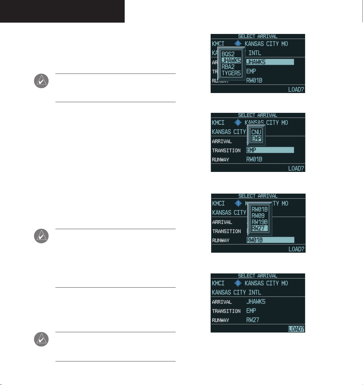
SUPPLEMENTAL FLIGHT DATA
Select Arrival
Select Arrival allows the pilot to choose a published
standard terminal arrival route (STAR) for the destination
airport, or replace a current arrival with a new selection.
NOTE: The pilot may also select an approach,
arrival and departure by pressing the MENU
key.
To select an arrival for a direct-to or flight
plan destination airport:
1. From an active flight plan, press the
to display the Procedures options window.
2. Turn the
large FMS
knob to highlight ‘Select
Arrival’, then press the
appears listing the available arrivals for the
destination airport.
FMS
3. Turn the
then press the
knob to select the desired arrival,
ENT
key. A window appears
listing the available transitions for the arrival.
4. Turn the
FMS
knob to select the desired transi-
tion, then press the
ENT
ENT
key. A window
key.
PROC
Figure 3.6.28 Arrival
key
Figure 3.6.29 Arrival Transition
3-44
NOTE: This runway window is not displayed for
every arrival. ‘ALL’ may appear in the runway
field, indicating that the arrival procedure applies
to all runways. For airports with parallel runways,
‘B’ may appear at the end of the runway designa
tion to indicate that the arrival procedure applies
to both runways.
5. A window may appear listing runways for the
FMS
arrival. Turn the
runway, then press the
highlighted, press the
NOTE: When adding an arrival to an active flight
plan, the pilot may need to remove a duplicate
destination waypoint from the flight plan list.
knob to select the desired
ENT
key. With ‘LOAD?’
ENT
key.
-
Figure 3.6.30 Arrival Runway
Figure 3.6.31 Select Arrival Window
190-00443-00 Rev. AGarmin G1000 PFD Pilot’s Guide for Mooney M20M & M20R
Page 47

SUPPLEMENTAL FLIGHT DATA
Select Departure
Select Departure allows the pilot to choose a published
standard instrument departure (SID) for the departure
airport, or replace the current departure with a new selec
tion. When using a direct-to, the G1000 uses the nearest
airport as a reference when displaying available depar
tures.
NOTE: The pilot may also select an approach, an
arrival and a departure by pressing the MENU
key.
To select a departure for the departure
airport:
PROC
1. From an active flight plan, press the
key
to display the Procedures options window.
2. Turn the
large FMS
Departure’, then press the
knob to highlight ‘Select
ENT
key. A window
appears listing the available departures for the
departure airport.
FMS
3. Turn the
ture, then press the
knob to select the desired depar-
ENT
key.
Activate Approach
Activate Approach allows the pilot to activate the ap
proach when ready to begin navigating the approach
course (cleared for the approach).
To activate the approach for a direct-to or
flight plan destination airport:
1. From an active flight plan, press the
PROC
to display the Procedures options window.
2. Turn the
Approach’, then press the
large FMS
knob to highlight ‘Activate
ENT
key.
Activate Vector-To-Final
Activate Vector-To-Final allows the pilot to activate the
final course segment of the approach. This option assumes
that the pilot will receive vectors to the final approach fix
(FAF) and provides guidance to intercept the final course,
before reaching the FAF.
To activate the approach with vectors to
final:
1. From an active flight plan, press the
PROC
to display the Procedures options window.
-
key
key
FMS
NOTE: This runway window is not displayed for
every departure. ‘ALL’ may appear in the runway
field, indicating that the departure procedure
applies to all runways. For airports with parallel
runways, ‘B’ may appear at the end of the runway
designation to indicate that the departure pro
cedure applies to both runways.
2. Turn the
To-Final’, then press the
-
knob to highlight ‘Activate Vector-
4. A window may appear listing runways for the
departure. Turn the
desired runway, then press the
FMS
knob to select the
ENT
key. The
transition window is now displayed.
FMS
5. Turn the
sition, then press the
highlighted, press the
190-00443-00 Rev. A Garmin G1000 PFD Pilot’s Guide for Mooney M20M & M20R
knob to select the desired tran-
ENT
key. With ‘LOAD?’
ENT
key.
ENT
key.
3-45
Page 48

SUPPLEMENTAL FLIGHT DATA
This page intentionally left blank.
3-46
190-00443-00 Rev. AGarmin G1000 PFD Pilot’s Guide for Mooney M20M & M20R
Page 49

REVERSIONARY MODE
3.7 REVERSIONARY MODE
The PFD is designed to enter reversionary (backup)
mode based on automatic fault monitoring and detec
tion, internal switching. Reversionary mode can also be
activated by manually pressing a dedicated DISPLAY
BACKUP button at the bottom of the Audio Panel (refer
to Audio Panel Pilot’s Guide). In reversionary mode, the
CDUs are re-configured to present the PFD symbology together with the engine parameters (engine parameters are
incorporated on the left side of the display).
-
Transition for the pilot is straightforward since PFD
parameters are presented in the same format as that prior
to the re-configuration. In the event of a display failure,
the pilot loses one NAV, one COM and GPS as displayed
below:
• PFD failure – NAV1, COM1 and GPS1 are lost
• MFD failure – NAV2, COM2 and GPS2 are lost
Figure 3.7.1 PFD Reversionary Mode
190-00443-00 Rev. A Garmin G1000 PFD Pilot’s Guide for Mooney M20M & M20R
3-47
Page 50

REVERSIONARY MODE
This page intentionally left blank.
3-48
190-00443-00 Rev. AGarmin G1000 PFD Pilot’s Guide for Mooney M20M & M20R
Page 51

ALERTS & ANNUNCIATIONS
3.8 ALERTS AND ANNUNCIATIONS
ALERTS WINDOW
Alerts appear in the Alerts window in the lower right
corner of the PFD. The term “Alerts” is an encompassing
term in that it includes advisories, cautions and warnings.
This window allows system alerts to be displayed simul
taneously. The Alerts window is enabled and disabled by
pressing the ALERTS softkey.
Figure 3.8.1 Alerts Window
A flashing “WARNING” softkey annunciation and an
aural tone (single chime every two seconds) are used to
alert the pilot of any warnings. The aural tone and flashing
“WARNING” annunciator continue until acknowledged
by the pilot. Pressing the WARNING softkey silences the
aural tone and stops the annunciator from flashing.
-
A flashing “ADVISORY” softkey annunciation (no aural
tone) is used to alert the pilot of any message advisories.
The flashing “ADVISORY” annunciator continues to flash
until acknowledged by the pilot. Pressing the ADVISORY
softkey stops the annunciator from flashing.
ANNUNCIATION WINDOW
The Annunciation window appears to the right of the
Vertical Speed Indicator when a WARNING or CAUTION
alert is issued. Warning alerts are displayed in red and
caution alerts are displayed in yellow.
NOTE: When new alerts appear, they are dis-
played with a separate white line at the top
of the annunciation window, regardless of
priority. Once they are acknowledged, they are
sequenced based on priority.
NOTE: For a detailed description of all annuncia-
tions and alerts, please refer to the Annunciations
and Alerts Pilot’s Guide.
A flashing “CAUTION” softkey annunciation and a
single aural tone (one chime) are used to alert the pilot of
any cautions. The flashing “CAUTION” annunciator con
tinues to flash until acknowledged by the pilot. Pressing
-
Figure 3.8.2 Annunciation Window
the CAUTION softkey stops the annunciator from flashing.
190-00443-00 Rev. A Garmin G1000 PFD Pilot’s Guide for Mooney M20M & M20R
3-49
3-49
Page 52

Garmin International, Inc.
1200 East 151st Street
Olathe, KS 66062, U.S.A.
p: 913.397.8200 f: 913.397.8282
Garmin AT, Inc.
2345 Turner Road SE
Salem, OR 97302, U.S.A.
p: 503.391.3411 f: 503.364.2138
Garmin (Europe) Ltd.
Unit 5, The Quadrangle
Abbey Park Industrial Estate
Romsey, SO51 9DL, U.K.
p: 44/1794.519944 f: 44/1794.519222
Garmin Corporation
No. 68, Jangshu 2nd Road
Shijr, Taipei County, Taiwan
p: 886/2.2642.9199 f: 886/2.2642.9099
www.garmin.com
190-00443-00 Rev. A © 2004 Garmin Ltd. or its subsidiaries
 Loading...