

Page 1

TM
TM
G1000
G1000
Multi Function Display Pilot’s Guide
for the Beechcraft A36/G36
Page 2

Record of Revisions
Revision Date of Revision Revision Page Range Description
A 07/14/05 All Initial Release
Garmin G1000 MFD Pilot’s Guide for the Beechcraft A36/G36 190-00574-00 Rev. A
Page 3

INTRODUCTION
8.1 INTRODUCTION
This G1000 Pilot’s Guide describes the operation of the Multi Function Display (MFD) installed in
Beechcraft A36/G36 aircraft.
DESCRIPTION
The display portion of the G1000 Integrated Cockpit
System installed in A36/G36 aircraft consists of two, 10.4inch liquid crystal displays (LCDs). During normal operation, the right display is configured as the Multi Function
Display (MFD).
OPTIONAL EQUIPMENT
This MFD Pilot’s Guide only covers the baseline
configuration of the G1000. Descriptions and procedures
relating to the following options for the A36/G36 are
covered in the G1000 Optional Equipment Pilot’s Guide:
• L-3 STORMSCOPE® WX-500 Series II Weather
Mapping Sensor
• L-3 SKYWATCH® Traffic Advisory System (Model
SKY497)
• L-3 SKYWATCH® HP Traffic Advisory System
(Model SKY899)
• Honeywell® KTA870 TAS/KMH880 Multi-Hazard
Awareness System
• Ryan TCAD 9900B and 9900BX
• GDL 69/69A XM® Radio System
Figure 8.1.1 G1000 MFD Splash Screen
Garmin G1000 MFD Pilot’s Guide for the Beechcraft A36/G36190-00574-00 Rev. A
8-1
Page 4

INTRODUCTION
MFD POWER-UP
Powering up the MFD is part of the system power up
procedure. See the G1000 System Overview Pilot’s Guide
for details.
Splash Screen Information
The MFD splash screen (Figure 8.1.1) displays general
system information such as software version and database
versions to the pilot when the G1000 system powers
up. To acknowledge the splash screen information and
proceed to the Navigation Map Page press the ENT key or
the right most softkey twice.
NOTE: Screen images in this pilot’s guide are
subject to change and may not reflect current
G1000 system software.
MFD BACKLIGHTING
See the Primary Flight Display Pilot’s Guide for
instructions on adjusting MFD backlighting.
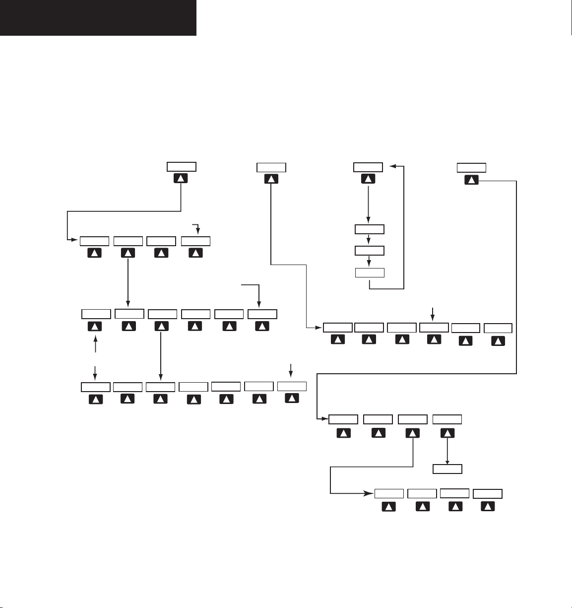
MFD SOFTKEYS
The MFD softkeys are located below the display screen
and provide control over flight management functions
including GPS Navigation and flight planning. Figure
8.1.3 shows an MFD flowchart identifying what functions
are available via the softkey labels.
TRAFFIC – pressing the TRAFFIC softkey
displays/removes Mode S Traffic on the
Navigation Map.
TOPO – pressing the TOPO softkey displays
or removes topographic information on the
Navigation Map.
TERRAIN – pressing the TERRAIN softkey
displays/removes terrain information on
the Navigation Map.
BACK – pressing the BACK softkey displays
the ENGINE and MAP top level softkeys.
DCLTR (declutter) – pressing the DCLTR softkey
removes map information in three levels.
CHKLIST (checklist) – pressing the CHKLIST
softkey displays the Checklist Page.
REVERSIONARY MODE
Should a failure occur in either display, the G1000
automatically enters reversionary mode. In reversionary mode, critical flight instrumentation is combined
with engine instrumentation on the remaining display.
Minimal navigation capability is also available on the
reversionary mode display. See the G1000 System Overview Pilot’s Guide for a detailed explanation of the reversionary mode.
8-2
The MFD softkeys perform the following functions:
ENGINE – Pressing the ENGINE softkey makes
available the LEAN and SYSTEM softkeys which
in turn access the Lean Page and the System Page,
respectively.
MAP – pressing the MAP softkey enables the follow-
ing softkeys:
Garmin G1000 MFD Pilot’s Guide for the Beechcraft A36/G36 190-00574-00 Rev. A
Page 5

INTRODUCTION
ELECTRONIC CHECKLISTS (OPTIONAL)
The G1000 Multi Function Display installed in the
A36/G36 provides optional checklists which allow a pilot
to quickly find the proper procedure on the ground and
during each phase of flight.
NOTE: The checklist information described in this
section is not intended to replace the checklist
information described in the Beechcraft A36/G36
Pilot’s Operating Handbook (POH) and the Pilot
Safety and Warning Supplements document.
NOTE: Garmin is not responsible for the content
of the checklists. User-defined checklists are created by the aircraft manufacturer. Additionally,
modifications or updates to the checklists are
coordinated through the aircraft manufacturer.
The user cannot edit the checklists.
Displaying the Checklist Page
The Splash Screen displays the current checklist file
that is installed for the Beechcraft A36/G36 aircraft. If no
checklist is present, then the Spalsh Sceen displays the text
“CHECKLIST FILE NOT PRESENT” and the CHKLIST
softkey is greyed out.
To select the Checklist Page:
1. From any page, press the
CHKLIST
softkey.
Selecting a Procedure Group
Depending on the specific airframe, there are a certain
number of groups of procedures with their respective
checklists available to the pilot.
To select a procedure group:
1. Press the
2. Turn the
CHKLIST
large FMS
softkey.
knob to select the ‘GROUP’
field.
3. Turn the
small FMS
procedure and press the
knob to select the desired
ENT
key.
Selecting a Checklist within the Procedure Group
1. Turn the
2. Turn the
large FMS
field.
FMS knob
and press the
knob to select the ‘Checklist’
to select the desired checklist
ENT
key.
Selecting a Checklist Item
Two methods are available to select a checklist item: (1)
pressing the
(1) Pressing the ENT key:
With the desired checklist displayed, turn the FMS
knob to move up and down the checklist and highlight
an item with a hollow white rectangle. The default color
for non-selected checklist items is blue and once the item
is highlighted, the color turns white. To select a checklist
item that is highlighted, press the ENT key. The selected
item turns green in color again for ease of identification,
and then a check mark is placed in the box next to the
item. As an item is selected, the next item is automatically
highlighted for selection.
ENT key; or (2) pressing the DONE softkey.
Garmin G1000 MFD Pilot’s Guide for the Beechcraft A36/G36190-00574-00 Rev. A
8-3
Page 6

INTRODUCTION
(2) Pressing the DONE Softkey: Pressing the DONE
One-Button Access to Emergency Procedures
softkey produces the same results as pressing the ENT
key.
NOTE: All warnings are displayed in yellow for
ease of identification.
the checklist page is displayed. Press the EMERGENCY
softkey at any time to immediately access the emergency
procedures.
Removing the check mark from a checklist item
Press the CLR key to remove a check mark from an
item.
Advancing to the Next Checklist
Once the last item in a checklist is selected, the ‘GO
TO THE NEXT CHECKLIST?’ text is highlighted. Press
the ENT key to advance to the next checklist displayed.
The EMERGENCY softkey is available at all times when
8-4
Garmin G1000 MFD Pilot’s Guide for the Beechcraft A36/G36 190-00574-00 Rev. A
Page 7

Exiting the Checklist Page
The EXIT softkey is available as long as the Checklist
Page is displayed. Press the EXIT softkey or momentarily
hold down the CLR key at anytime to exit the Checklist
Page and return to the last page that was displayed before
the Checklist Page was selected.
Checklist Group
Checklist Number
INTRODUCTION
Checklist Page
Softkeys
Checklist Page
Indicator
Figure 8.1.2 Checklist Page (typical)
Emergency
Softkey
Garmin G1000 MFD Pilot’s Guide for the Beechcraft A36/G36190-00574-00 Rev. A
8-5
Page 8
INTRODUCTION
DCLTR
TRAFFIC
TOPO
BACK
TERRAIN
DCLTR-2
DCLTR-3
DCLTR-1
Press the BACK softkey on this level to
return to the top softkey level
CHKLIST
EXIT
EMERGCY
ENGINE
DCLTR
MAP
ENGINE
CHKLIST
CLR
DONE
The DONE softkey changes to UNDO when the checklist
item is already checked
MAP
XM LTNG
STRMSCP
OPTIONAL
BACK
DEC FUEL
SYSTEM
ENGINE
LEAN
ENGINE
BACK
SYSTEM
LEAN
ENGINE
ENGINE
LEAN
BACK
SYSTEM
Press the ENGINE sof tkey on any level to
return to the LEAN and SYSTEM softkey level
Press the BACK softkey on this level to
return to the top softkey level
Press the BACK softkey on this level to
return to the top softkey level
Press the BACK softkey on this level to
return to the top softkey level
ASSIST
CYL SLCT
INC FUEL
RST FUEL
8-6
Figure 8.1.3 MFD Softkeys
Garmin G1000 MFD Pilot’s Guide for the Beechcraft A36/G36 190-00574-00 Rev. A
Page 9

INTRODUCTION
MFD PAGE GROUPS
The MFD displays GPS/Navigation flight information
in four main page groups:
• Map (MAP):
Navigation Map Page
Traffic Map Page
Terrain Proximity Page
• Waypoint (WPT) :
Airport Information Page
Intersection Information Page
NDB Information Page
VOR Information Page
User Waypoint Information Page
• Auxiliary (AUX):
Trip Planning Page
Utility Page
GPS Status Page
System Setup Page
System Status Page
• Nearest (NRST):
Nearest Airports Page
Nearest Intersections Page
Nearest NDB Page
Nearest VOR Page
Nearest User Waypoints Page
Nearest Frequencies Page
Neatest Airspaces Page
To select a specific page group:
1. Turn the
large FMS
knob until the desired page
group is selected.
Active Page group is
highlighted
Figure 8.1.4 Page Group Window
Currently
selected page is
highlighted
To select a different page within the group:
1. Turn the
small right FMS
knob. As the knob is
turned, the bottom right corner of each page
indicates the page group that is currently being
displayed (e.g., MAP or NRST, etc.), the number
of pages available within that group (indicated
by rectangle icons) and the placement of the
current page within that group (indicated by a
solid cyan rectangle icon). The page group and
active page title window are displayed below
the status bar.
Page Group
Figure 8.1.5 Page Title Window
Active Page Title
Garmin G1000 MFD Pilot’s Guide for the Beechcraft A36/G36190-00574-00 Rev. A
8-7
Page 10
INTRODUCTION
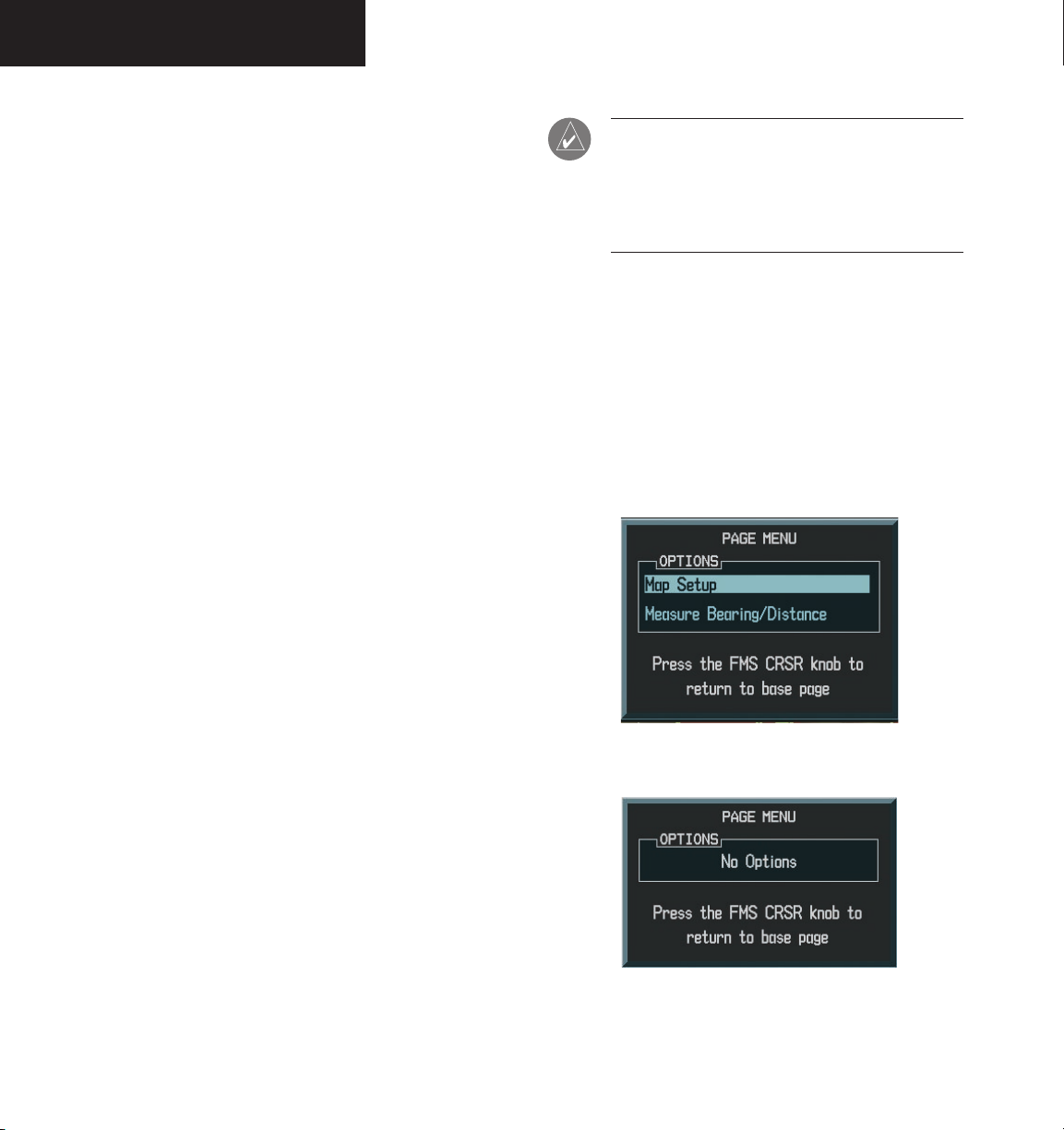
WORKING WITH MENUS
Much of the operation of the G1000 MFD is
accomplished using a menu interface. The G1000 has
a bezel-mounted dedicated menu key (MENU) when
pressed, displays a context-sensitive list of options. This
options list allows the pilot to access additional features
or make settings changes which specifically relate to the
currently displayed page. Some menus provide access to
additional submenus that are used to view, edit, select,
and review options. Some menus display ‘NO OPTIONS’
when there are no options for the page selected.
The main keys which are used in association with all
page group operations are listed below:
• CLR – erases information or cancels an entry.
Press and hold CLR to immediately display the
Navigation Map Page, regardless of the page
currently displayed.
• ENT – accepts a menu selection or data entry.
Approves an operation or completes data entry.
Also confirms information.
• BACK – resets the MFD softkeys to their default
settings (ENGINE, MAP, DCLTR, MODE, VIEW,
etc).
• DCLTR – removes information from the moving
map in a progressive manner with each key-press.
• MENU – displays a context-sensitive list of
options that allows access to additional features or
that allows the pilot to change the settings which
relate to the currently displayed page.
NOTE: Data is entered using the large and small
FMS knob. Practice with them to become efficient at entering data. This will greatly reduce
the amount time spent operating the MFD in
flight.
If there are more options than can be displayed turn
the FMS knob to scroll through the list to identify them.
In all cases, once the menu is displayed the FMS knob is
turned to highlight an item and the ENT key is pressed
to select that item or the CLR key removes the menu and
cancels the operation. Pressing the softkeys does not
display a menu or submenu.
Figure 8.1.6 Menu with Options
8-8
Figure 8.1.7 Menu with No Options
Garmin G1000 MFD Pilot’s Guide for the Beechcraft A36/G36 190-00574-00 Rev. A
Page 11
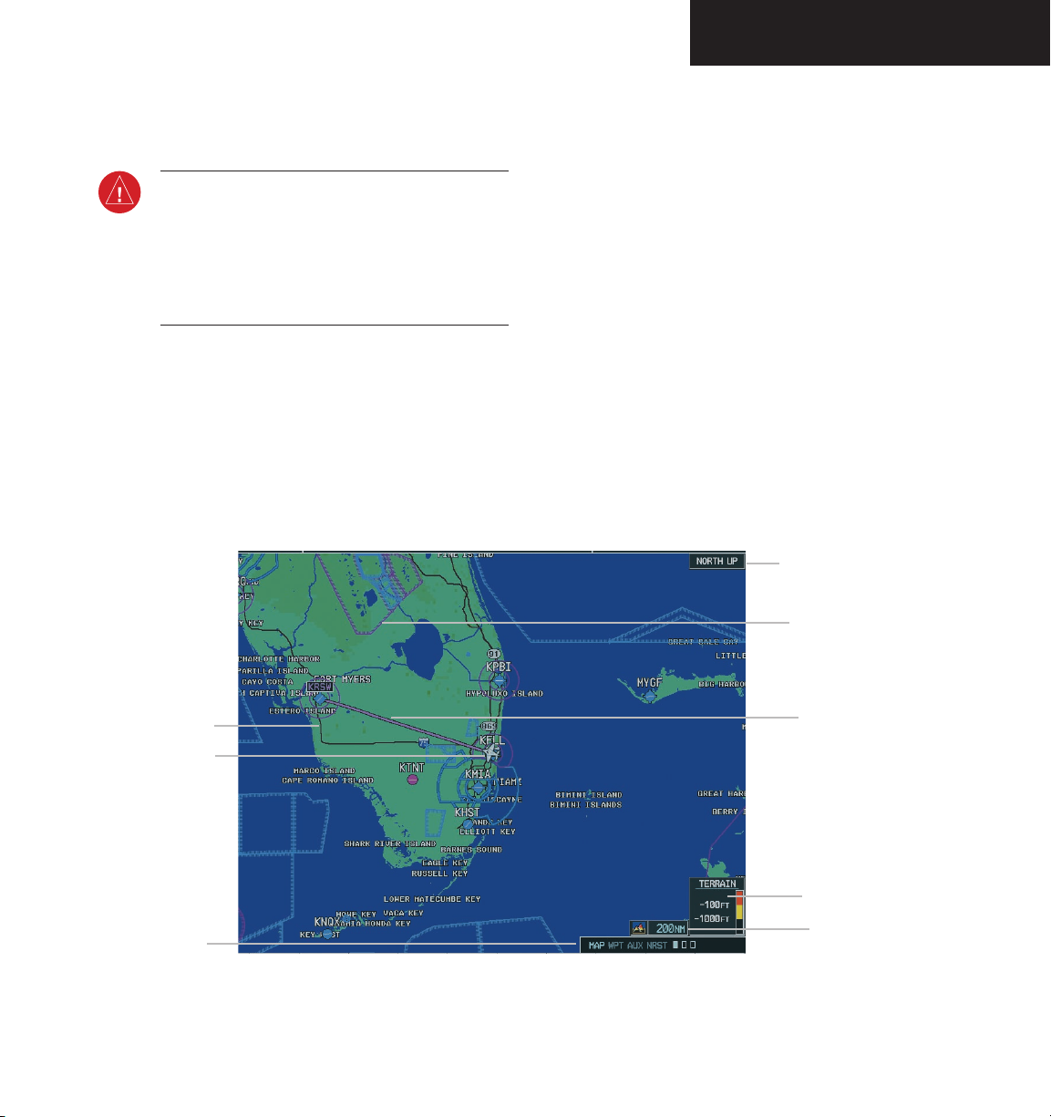
NAVIGATION MAP PAGE
8.2 NAVIGATION MAP PAGE
WARNING: Use of the Navigation Map Page for
pilotage navigation is prohibited. The Navigation
Map is intended only to enhance situational
awareness. Navigation is to be conducted
using only current charts, data, and authorized
navigation facilities.
The Navigation Map Page is the first page in the map
page group and provides the pilot with the following
GPS/Navigation display capability:
• Map display showing airports, navaids, airspaces,
land data (highways, cities, lakes, rivers, borders,
etc.) with names (labels)
• Map pointer information (distance and bearing
to pointer, location of pointer, name and other
pertinent information)
• TIS Traffic Display
• Obstacle Display
• Map Zoom Range Legend
• Wind Direction and Speed
• Heading Indication
• Aircraft icon representing present position
• Icons for enabled map features
• Track Vector
• Topography Scale
• Fuel Range Ring
• Topography Data
• Terrain Proximity Data
Map Orientation
Airspace Boundries
Interstate
Highways
Own Aircraft
Page Groups
Course Line
Terrain Scale
Map Scale
Legend
Figure 8.2.1 Navigation Map Page
(not all features shown)
Garmin G1000 MFD Pilot’s Guide for the Beechcraft A36/G36190-00574-00 Rev. A
8-9
Page 12

NAVIGATION MAP PAGE
To select the Navigation Map Page:
1. Turn the
group.
2. Turn the
tion Map Page. The page group name and page
title is displayed below the navigation status
bar; MAP – NAVIGATION MAP. In addition to
turning the
Navigation Map Page can be selected from any
page by pressing and momentarily holding the
CLR
large FMS
knob to select the Map Page
small FMS
large and small FMS
(DFLT MAP) key.
knob to select the Naviga-
knobs, the
8-10
Garmin G1000 MFD Pilot’s Guide for the Beechcraft A36/G36 190-00574-00 Rev. A
Page 13

NAVIGATION MAP PAGE
NAVIGATION MAP PAGE OPERATIONS
The following Navigation Map Page operations can be
performed:
• Changing the Map Orientation
• Selecting a Map Range
• Using the Auto Zoom Feature
• Identifying Aviation Map Data
• Decluttering the Map
• Panning the Map
• Displaying Topographic Information on the Navi
gation Map Page
• Displaying Terrain Information on the Navigation
Map Page
• Displaying Traffic on the Navigation Map Page
• MFD Navigation Status Window
• Navigation Map Page Options Menu
Changing the Map Orientation
See the map setup section of this MFD Pilot’s Guide for
instructions on how to change the map orientation.
-
Selecting a Map Range
The Navigation Map Page can be set to 23 different
range settings from 500 feet to 2000 nautical miles. The
current range is indicated in the lower right corner of the
Navigation Map Page and represents the top-to-bottom
distance covered by the map. To change the map range
turn the joystick counter-clockwise to zoom in, turn it
clockwise to zoom out.
Using the Auto Zoom Feature
The autozoom feature automatically adjusts the map
from an enroute range of 2000 nm through each lower
range, stopping at a range of 1.5 nm as the aircraft
approaches the destination waypoint. See the Map Setup
section in this MFD Pilot’s Guide for instructions on
enabling/disabling the autozoom feature.
Map Range
Indicator
Figure 8.2.2 Map Range
Garmin G1000 MFD Pilot’s Guide for the Beechcraft A36/G36190-00574-00 Rev. A
8-11
Page 14

NAVIGATION MAP PAGE
Identifying Aviation Map Data
The following aviation data is displayed on the
Navigation Map Page:
Airport Symbols:
• Non-towered airports (purple in color).
• Towered airports (blue in color).
• Non-serviced airports (displayed as solid circle
icons). See Appendix F for symbology definitions.
• Serviced airports (displayed as circles with protruding tick marks pointing to the top, bottom,
left, and right portions of the screen).
Classification
• Unclassified airports (displayed with a question
mark “?” character centered within the airport
symbol).
• Restricted airports (displayed with the letter “R”
centered within the airport symbol).
• Hard surface public airports (displayed with the
airports longest runway oriented according to
the direction in which it runs centered within the
airport symbol).
• Heliports (displayed with the letter “H” centered
within the heliport symbol).
• Soft surface public airports (displayed with a
hollow circle in the center of the airport symbol).
Airspace:
The Navigation Map Page displays airspace as one of
the following colors:
• Blue:
ICAO control area
Class B, Alert area
Caution area, Danger area, Prohibited area
Restricted area, Training area
Unknown area, Warning area
Terminal Zone Airspace (ATZ), Class D
:
• Purple:
Class C
ICAO terminal control area
Terminal radar service area (TRSA)
Mode C area
Military operations area (MOA)
Mode C
Class A
Class E
Line Style:
The Navigation Map Page displays airspace as one of
the following line styles:
• Solid line:
Class C
ICAO control area
ICAO terminal control area
Class B, Terminal radar service area
Mode C, Class A
• Dashed line:
Mode C tower area
Class D, Class E
• Consecutive parallel lines forming a
boundary defining the airspace:
Military operations area (MOA)
Warning area, Alert area, Caution area
Danger area, Prohibited area
Restricted area, Training area
Unknown area, Terminal Zone Airspace (ATZ)
NOTE: See Appendix F for a complete descrip-
tion of the aviation map symbology used on the
Navigation Map Page.
8-12
Garmin G1000 MFD Pilot’s Guide for the Beechcraft A36/G36 190-00574-00 Rev. A
Page 15

Decluttering the Map
The Navigation Map Page can be quickly decluttered
by repeatedly pressing the DCLTR softkey until the desired
detail is displayed. The declutter level label is displayed
above the DCLTR softkey. Note that during an instrument
approach, automatic decluttering takes place. Table 8.2.1
lists the features that are turned off at each declutter
level.
NAVIGATION MAP PAGE
NOTE: Some of the map features are automati-
cally removed at certain zoom ranges due to the
map setup configuration for each map item.
NOTE: “SUA” listed in the table below stands
for Special Use Airspace. These are controlled
airspaces, military zones, etc.
Map Features always
No Declutter Declutter ( –1) Declutter (-2) Declutter (-3)
displayed
Flight plan route lines All Map features
River/Lakes Names Only User waypoints Large Airports
are visible
Flight plan route waypoints Land/Country Text
Rivers/Lakes
Topography data
Terrain Proximity data
Large City VORs Small Airports
Medium City NDBs SUA Group 3
Small City Intersections SUA Group 4
Latitude/Longitude Grid Medium Airports
Map Borders ----------- SUA Group 0 Runway Labels
Bearing Line Freeways SUA Group 1
Lightning Strike data (when
National Highways SUA Group 2
Stormscope installed)
Nexrad data Local Highways SUA Group 5
Traffic Symbols
Traffic Labels
Local Roads SUA Group 6
Local Road Labels SUA Group 7
Railroads
Obstacles
Major Political Boundaries
Table 8.2.1 Map Declutter Levels
Garmin G1000 MFD Pilot’s Guide for the Beechcraft A36/G36190-00574-00 Rev. A
8-13
Page 16

NAVIGATION MAP PAGE
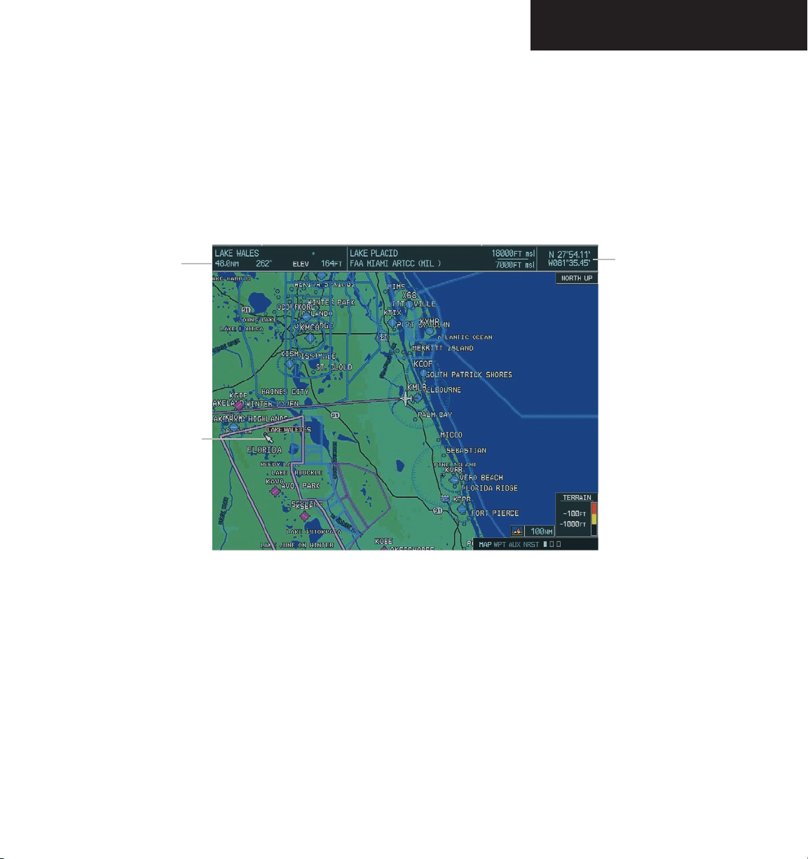
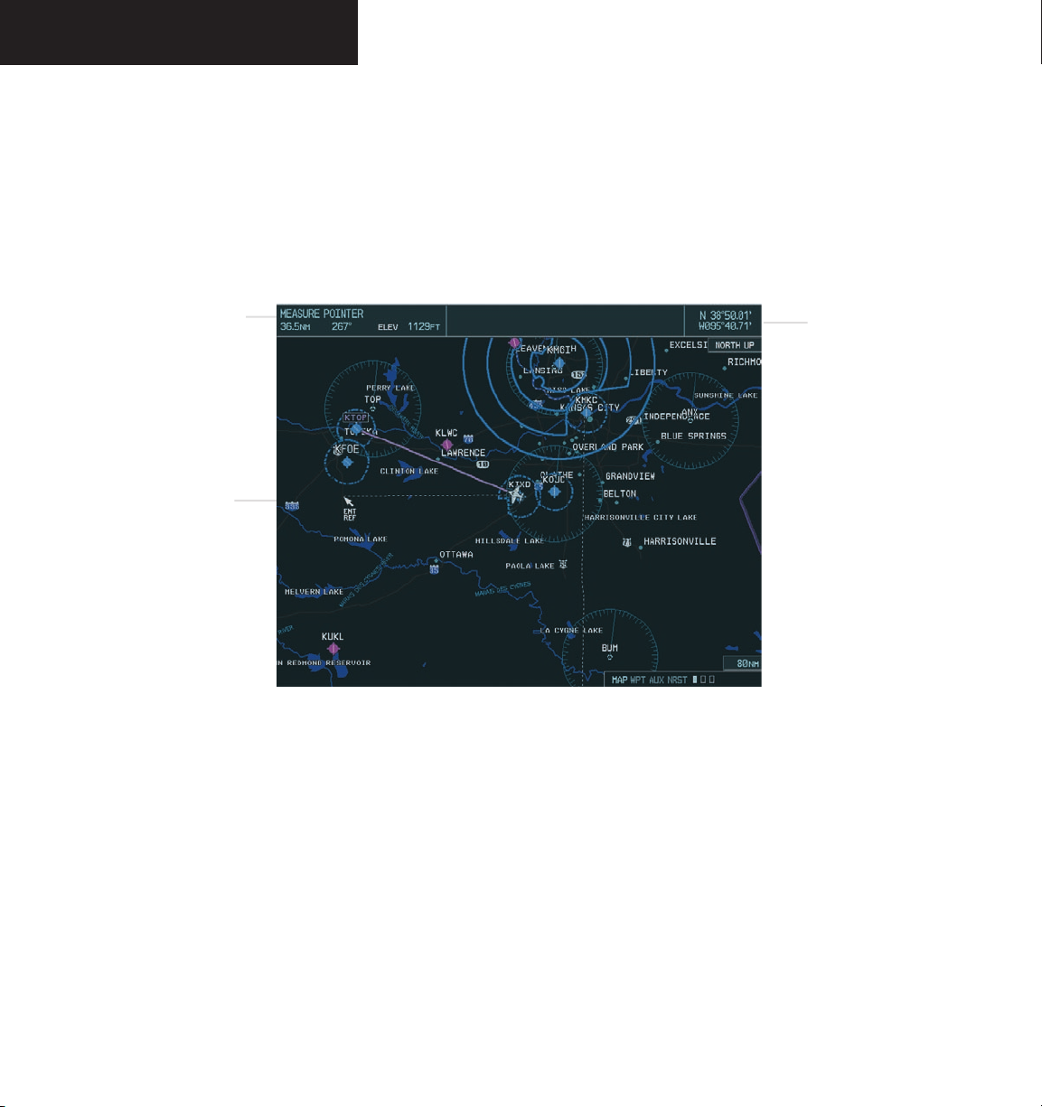
Map Panning
Map panning moves the map beyond its current
limits without adjusting the map range. When the
panning function is selected by pushing in the joystick,
a panning arrow flashes on the map display. A window
also appears at the top of the map display showing the
latitude/longitude position of the pointer, the bearing and
distance to the pointer from the aircraft’s present position,
and the elevation of the land at the position of the pointer.
When the panning arrow crosses an airspace boundary,
the boundary is highlighted and airspace information
is displayed at the top of the display. The information
includes the name and class of airspace, the ceiling in feet
expressed in Mean Seal Level (MSL), and the floor in feet
MSL.
NOTE: The airspace boundary stays highlighted
for approximately four seconds before returning
to normal shading.
To pan the map:
1. Push in the
joystick
to display the panning
arrow.
2. Push in and move the
joystick
in the general
direction of the desired destination to place
the panning arrow at the destination location. When the panning arrow is placed on an
object, the name of the object is highlighted
(even if the name wasn’t originally displayed
on the map). This feature applies to everything
displayed on the map except route lines. When
any map feature or object is selected on the
map display, features or objects are displayed
in the box located at the top of the display.
From here, the pilot can designate the waypoint
as the Direct-to destination. When the
panning arrow crosses an airspace boundary,
the boundary is highlighted and airspace information is displayed at the top of the display.
3. To remove the panning arrow and return to
the present position, push in the
joystick
.
8-14
Garmin G1000 MFD Pilot’s Guide for the Beechcraft A36/G36 190-00574-00 Rev. A
Page 17
NAVIGATION MAP PAGE
Distance,
bearing
and elevation
Panning
Arrow
Latitude and longitude
position of pointer
Figure 8.2.3 Map Panning
Garmin G1000 MFD Pilot’s Guide for the Beechcraft A36/G36190-00574-00 Rev. A
8-15
Page 18

NAVIGATION MAP PAGE
Displaying Topographic Data on the Navigation Map Page
The Navigation Map Page displays various shades of
topography land colors representing the rise and fall of
land elevation similar to aviation sectional charts. The
Navigation Map Page can display a topographic scale
representing various key points of terrain elevation colors
with their associated elevation value labeled.
To display topographic data on the Navigation Map Page:
MAP
1. Press the
2. Press the
softkey.
TOPO
softkey. Topo data can also
be displayed on the Navigation Map Page by
using the ‘On/Off’ topo data map setup feature.
See the Navigation Map Page setup menu section.
On-screen map
maximum
elevation
On-screen map
minimum
elevation
8-16
Aircraft altitude
Maximum
Minimum
Figure 8.2.4 Topography Range
Garmin G1000 MFD Pilot’s Guide for the Beechcraft A36/G36 190-00574-00 Rev. A
Ground elevation
Page 19

NOTE: Press the
topo data from the Navigation Map Page.
When topo data is removed from the page,
the Jeppesen Nav data is presented on a black
background.
TOPO
softkey again to remove
Displaying Terrain Information on the Navigation Map Page
Terrain data can be displayed on the Navigation
Map Page by pressing the
symbology (mountain icons) appear next to the map
range in the bottom right corner of the page indicating
the presence of terrain data on the map. See the
Terrain Proximity Page section for a terrain color
interpretation chart.
To display terrain data on the Navigation
Map Page:
1. Press the
2. Press the
MAP
TERRAIN
softkey again to remove terrain data from the
Navigation Map Page.
TERRAIN softkey. Terrain
softkey.
softkey. Press the
TERRAIN
NAVIGATION MAP PAGE
Displaying Traffic on the Navigation Map Page
Pressing the TRAFFIC softkey displays Traffic
Information Service (TIS) traffic on the Navigation Map
Page. TIS is a ground-based service providing relative
location of all ATCRBS Mode-A and Mode-C transponder
equipped aircraft within a specified service volume.
The TIS ground sensor uses real time track reports to
generate traffic notification. Surveillance data includes
all transponder-equipped aircraft within the coverage
volume. The G1000 displays up to eight traffic targets
within a 7.5 nautical mile radius, from 3,000 feet below to
3,500 feet above the requesting aircraft. See Appendix E
for a full description of TIS. A traffic symbol appears next
to the map range in the bottom right corner of the display
indicating the presence of traffic data on the map.
To display traffic on the Navigation Map
Page:
MAP
1. Press the
2. Press the
TRAFFIC
Navigation Map Page.
NOTE: Traffic and terrain data can also be
displayed by using the ‘On/Off’ Navigation Map
Page option. See the Navigation Map Page setup
section for details.
softkey.
TRAFFIC
softkey. Press the
softkey again to remove traffic from the
Garmin G1000 MFD Pilot’s Guide for the Beechcraft A36/G36190-00574-00 Rev. A
8-17
Page 20
NAVIGATION MAP PAGE
MFD Data Bar
The MFD Navigation Status Window displays four,
user-configurable fields which can display the following
data:
• Bearing to next waypoint (BRG)
• Distance to next waypoint (DIS)
• Desired track to next waypoint (DTK)
• En-route safe altitude (ESA)
• Estimated Time of Arrival (ETA)
• Estimated Time Enroute (ETE)
• Ground Speed (GS)
• Maximum Safe Altitude (MSA)
• Track angle error (TKE)
• Track angle (TRK)
• Vertical speed required (VSR)
• Cross track error (XTK)
• Currently selected MFD page title
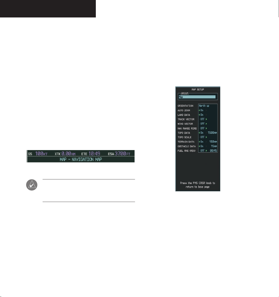
Figure 8.2.5 MFD Data Bar (default)
Map Setup
The first option is ‘Map Setup’ which is used to configure the Navigation Map Page including map orientation,
land data enable/disable, Jeppesen data enable/disable,
automatic zoom, airspace boundaries, and text size.
Map Group Options
8-18
NOTE: Instructions on changing a data field on
the MFD Data Bar is given in the System Setup
Section.
Navigation Map Page Options Menu
The Navigation Map Page can be customized using op-
tions listed in the Navigation Map Page menu. To display
the menu, press the MENU key (with the Navigation Map
Page displayed). Two options are available: Map Setup,
and Measure Bearing/Distance.
Garmin G1000 MFD Pilot’s Guide for the Beechcraft A36/G36 190-00574-00 Rev. A
Figure 8.2.5 Map Group Setup Options
Page 21

NAVIGATION MAP PAGE
Orientation
There are four map orientation selections: North up,
Track up, DTK up, and HDG up.
• North up fixes the top of the map to a north head
-
ing.
• Track up adjusts the top of the map display to the
current ground track.
• Desired Track Up (DTK up) fixes the top of the
map display to the desired course.
• Heading Up (HDG up) fixes the top of the map
display to the current aircraft heading.
NOTE: The Navigation Map Page orientation
default setting is ‘North Up’.
To change the map orientation:
1. With the Navigation Map Page displayed, press
the
MENU
key to display the Navigation Map
Page Menu. The cursor flashes on the ‘Map
Setup’ option.
ENT
2. Press the
key. The Map Setup Menu is
displayed.
3. Turn the
group and press the
4. Turn the
small FMS
large FMS
knob to select the ‘
ENT
key.
Map’
knob to highlight the
‘ORIENTATION’ field.
5. Turn the
small FMS
orientation and press the
6. Press the
FMS
knob to select the desired
ENT
key.
knob to return to the Navigation
Map Page.
Garmin G1000 MFD Pilot’s Guide for the Beechcraft A36/G36190-00574-00 Rev. A
8-19
Page 22

NAVIGATION MAP PAGE
Auto Zoom
The automatic zoom feature automatically adjusts
the map range from 2000 nm through each lower
range, stopping at 1.5 nm as the aircraft approaches the
destination waypoint.
To enable/disable automatic zoom:
1. With the Navigation Map Page displayed, press
the
MENU
key to display the Navigation Map
Page Menu. The cursor flashes on the ‘Map
Setup’ option.
ENT
2. Press the
key. The Map Setup Menu is
displayed.
3. Turn the
group and press the
4. Turn the
small FMS
large FMS
knob to select the ‘
ENT
key.
Map’
knob to highlight the ‘AUTO
ZOOM’ field.
5. Turn the
and press the
6. Press the
small FMS
FMS
knob to select ‘On’ or ‘Off’
ENT
key.
knob to return to the Navigation
Map Page.
Land Data
The Navigation Map Page can display background land
data (roads, lakes, borders, etc). The background land
data can also be removed from the display (turned off).
To enable/disable land data:
1. With the Navigation Map Page displayed, press
the
MENU
key to display the Navigation Map
Page Menu. The cursor flashes on the ‘Map
Setup’ option.
ENT
2. Press the
key. The Map Setup Menu is
displayed.
3. Turn the
group and press the
4. Turn the
small FMS
large FMS
knob to select the ‘
ENT
key.
knob to highlight the ‘LAND
DATA’ field.
5. Turn the
and press the
6. Press the
small FMS
FMS
knob to select ‘On’ or ‘Off.’
ENT
key.
knob to return to the Navigation
Map Page.
Map’
8-20
Garmin G1000 MFD Pilot’s Guide for the Beechcraft A36/G36 190-00574-00 Rev. A
Page 23

NAVIGATION MAP PAGE
Track Vector
The Navigation Map Page can display a track vector as
a dashed cyan line segment with an arrowhead attached
to the end, extended to a predicted location in 60 seconds
along the current aircraft track. The track vector is useful
in minimizing track angle error.
To enable/disable the track vector:
1. With the Navigation Map Page displayed, press
the
MENU
key to display the Navigation Map
Page Menu. The cursor flashes on the ‘Map
Setup’ option.
ENT
2. Press the
key. The Map Setup Menu is
displayed.
3. Turn the
group and press the
4. Turn the
small FMS
large FMS
knob to select the ‘
ENT
key.
Map’
knob to highlight the
‘TRACK VECTOR’ field.
5. Turn the
‘Off’. Press the
small FMS
knob to select ‘On’ or
ENT
key to accept the selected
option.
FMS
6. Press the
knob to return to the Navigation
Map Page.
Wind Vector
The wind vector box is displayed in the upper right
corner of the Navigation Map Page and displays wind
direction and speed (in knots). Wind direction is
indicated by a 360 degree pointing arrow.
To enable/disable the wind vector box:
1. With the Navigation Map Page displayed, press
the
MENU
key to display the Navigation Map
Page Menu. The cursor flashes on the ‘Map
Setup’ option.
ENT
2. Press the
key. The Map Setup Menu is
displayed.
3. Turn the
group and press the
4. Turn the
small FMS
large FMS
knob to select the ‘
ENT
key.
Map’
knob to highlight the ‘WIND
VECTOR’ field.
5. Turn the
‘Off’. Press the
small FMS
knob to select ‘On’ or
ENT
key to accept the selected
option.
FMS
6. Press the
knob to return to the Navigation
Map Page.
Garmin G1000 MFD Pilot’s Guide for the Beechcraft A36/G36190-00574-00 Rev. A
8-21
Page 24

NAVIGATION MAP PAGE
Nav Range Ring
The Nav range ring shows the direction of travel
(ground track) on a rotating compass card. The range of
the Nav compass is determined by the map range, 125 feet
(500 feet map range) to 500 nm (2000 nm map range).
Navigation Map Page using the ‘TOPO DATA’ setting. The
topo data range is the maximum map range that topo data
is displayed.
To enable/disable the Nav range ring:
1. With the Navigation Map Page displayed, press
the
MENU
key to display the Navigation Map
Page Menu. The cursor flashes on the ‘Map
Setup’ option.
ENT
2. Press the
key. The Map Setup Menu is
displayed.
3. Turn the
group and press the
4. Turn the
small FMS
large FMS
knob to select the ‘
ENT
key.
Map’
knob to highlight the ‘NAV
RANGE RING’ field.
5. Turn the
‘Off’. Press the
small FMS
knob to select ‘On’ or
ENT
key to accept the selected
option.
Topo Data
Topographic data can be enabled or disabled on the
To enable/disable topo data and to select a
topo data range:
1. With the Navigation Map Page displayed, press
the
MENU
key to display the Navigation Map
Page Menu. The cursor flashes on the ‘Map
Setup’ option.
ENT
2. Press the
key. The Map Setup Menu is
displayed.
3. Turn the
group and press the
4. Turn the
small FMS
large FMS
knob to select the ‘
ENT
key.
Map’
knob to highlight the ‘TOPO
DATA’ field.
5. Turn the
small FMS
knob to select ‘On’ or
‘Off’.
8-22
6. Press the
Map Page.
FMS
knob to return to the Navigation
Garmin G1000 MFD Pilot’s Guide for the Beechcraft A36/G36 190-00574-00 Rev. A
ENT
6. Press the
key to accept the selected option.
The flashing cursor highlights the range field.
TOPO ranges are from Off to 2000 nm.
7. To change the TOPO range setting, turn the
small FMS
8. Turn the
range and press the
9. Press the
knob to display the range list.
small FMS
FMS
knob to select the desired
ENT
key.
knob to return to the Navigation
Map Page.
NOTE: When topographic data is removed from
the Navigation Map Page, all cartographic data
is automatically removed and the Jeppesen Nav
data is presented on a black background.
Page 25

NAVIGATION MAP PAGE
Topo Range
The topo range setting enables or disables the
topography range box located in the lower right corner of
the Navigation Map Page.
To enable/disable the topo range box:
1. With the Navigation Map Page displayed, press
the
MENU
key to display the Navigation Map
Page Menu. The cursor flashes on the ‘Map
Setup’ option.
ENT
2. Press the
key. The Map Setup Menu is
displayed.
3. Turn the
group and press the
4. Turn the
small FMS
large FMS
knob to select the ‘
ENT
key.
Map’
knob to highlight the ‘TOPO
Range’ field.
5. Turn the
small FMS
knob to select ‘On’ or
‘Off’.
ENT
6. Press the
key to accept the selected
option.
FMS
7. Press the
knob to return to the Navigation
Map Page.
Terrain Data
Terrain data can be enabled or disabled on the
Navigation Map Page using the ‘TERRAIN DATA’ setting.
A data range can also be selected. The data range is the
maximum map range that terrain data is displayed.
To enable/disable terrain data and to select
a terrain data range:
1. With the Navigation Map Page displayed, press
the
MENU
key to display the Navigation Map
Page Menu. The cursor flashes on the ‘Map
Setup’ option.
ENT
2. Press the
key. The Map Setup Menu is
displayed.
3. Turn the
group and press the
4. Turn the
small FMS
large FMS
knob to select the ‘
ENT
key.
knob to highlight the ‘TER-
RAIN DATA’ field.
5. Turn the
small FMS
knob to select ‘On’ or
‘Off’.
ENT
6. Press the
key to accept the selected option.
The flashing cursor highlights the range field.
TERRAIN ranges are from Off to 2000 nm.
Map’
7. To change the TERRAIN range setting, turn the
small FMS
8. Turn the
range and press the
9. Press the
knob to display the range list.
small FMS
FMS
knob to select the desired
ENT
key.
knob to return to the Navigation
Map Page.
Garmin G1000 MFD Pilot’s Guide for the Beechcraft A36/G36190-00574-00 Rev. A
8-23
Page 26

NAVIGATION MAP PAGE
Obstacle Data
Obstacle data can be enabled or disabled on the
Navigation Map Page using the ‘OBSTACLE DATA’ setting.
A data range can also be selected. The data range is the
maximum map range that terrain data is displayed.
To enable/disable obstacle data and to
select a terrain data range:
1. With the Navigation Map Page displayed, press
the
MENU
key to display the Navigation Map
Page Menu. The cursor flashes on the ‘Map
Setup’ option.
ENT
2. Press the
key. The Map Setup Menu is
displayed.
3. Turn the
group and press the
4. Turn the
small FMS
large FMS
knob to select the ‘
ENT
key.
Map’
knob to highlight the
‘OBSTACLE DATA’ field.
5. Turn the
small FMS
knob to select ‘On’ or
‘Off’.
ENT
6. Press the
key to accept the selected option.
The flashing cursor highlights the range field.
OBSTACLE ranges are from Off to 50 nm.
7. To change the OBSTACLE range setting, turn
the
small FMS
8. Turn the
range and press the
9. Press the
knob to display the range list.
small FMS
FMS
knob to select the desired
ENT
key.
knob to return to the Navigation
Map Page
Fuel Range Ring (Fuel RNG) (RSV)
The Navigation Map Page can display a fuel range
ring which shows the flight distance that the aircraft has
remaining. A dashed green circle indicates the transition
range to reserve fuel. A solid green circle indicates the
range of all fuel, including the reserve fuel. If only reserve
fuel remains, the range is indicated by a solid yellow
circle.
To enable/disable the fuel range ring and to
select a fuel range time:
1. With the Navigation Map Page displayed, press
the
MENU
key to display the Navigation Map
Page Menu. The cursor flashes on the ‘Map
Setup’ option.
ENT
2. Press the
key. The Map Setup Menu is
displayed.
3. Turn the
group and press the
4. Turn the
small FMS
large FMS
knob to select the ‘
ENT
key.
Map’
knob to highlight the ‘FUEL
RNG (RSV)’ field.
5. Turn the
small FMS
knob to select ‘On’ or
‘Off’.
ENT
6. Press the
key to accept the selected option.
The flashing cursor highlights the fuel reserve
time field. The time indicated is the time the
aircraft can fly with remaining fuel on board.
7. To change the reserve fuel time, turn either the
FMS knob to enter a time (00:00 to 23:59;
hours:minutes). The default setting is 00:45
ENT
minutes. Press the
key.
8-24
FMS
8. Press the
knob to return to the Navigation
Map Page.
Garmin G1000 MFD Pilot’s Guide for the Beechcraft A36/G36 190-00574-00 Rev. A
Page 27
NAVIGATION MAP PAGE
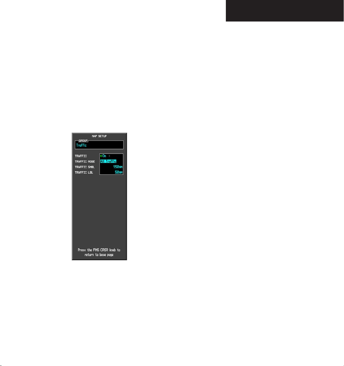
Traffic Group
The display of traffic information on the Navigation
Map Page closely resembles TCAS display symbology.
Traffic is only displayed on the Navigation Map Page if
aircraft heading data is available. If heading is not
available, traffic advisories are displayed as non-bearing
banners on the Navigation Map Page.
To enable/disable traffic data on the Navigation Map Page:
1. With the Navigation Map Page displayed, press
the
MENU
key to display the Navigation Map
Page Menu. The cursor flashes on the ‘Map
Setup’ option.
ENT
2. Press the
key. The Map Setup Menu is
displayed
3. Turn the
group. Press the
small FMS
knob to select the ‘Traffic’
ENT
key. The cursor flashes
on the ‘TRAFFIC’ field.
4. Turn the
small FMS
knob to select ‘On’ or
‘Off’.
ENT
5. Press the
key to accept the selected
option.
FMS
6. Press the
knob to return to the Navigation
Map Page.
The ‘Traffic’ mode selects which traffic is displayed (all
traffic, traffic and proximity advisories, or traffic advisories
only). The traffic symbol is the symbol used to depict the
type of traffic:
Figure 8.2.6 Traffic Group Options
Garmin G1000 MFD Pilot’s Guide for the Beechcraft A36/G36190-00574-00 Rev. A
• Traffic Advisories (TA) – Yellow
• Proximity Advisories (PA) – White
• Other – White
Proximity Advisories (PAs) are displayed as solid white
Beechcrafts. PAs are defined as traffic within the 4.0 nm
range, within ± 1200 ft. of altitude separation, and are not
traffic advisories (TAs).
8-25
Page 28

NAVIGATION MAP PAGE
To select a traffic mode:
1. With the Navigation Map Page displayed, press
the
MENU
key to display the Navigation Map
Page Menu. The cursor flashes on the ‘Map
Setup’ option.
ENT
2. Press the
key. The Map Setup Menu is
displayed.
3. Turn the
group Press the
small FMS
knob to select the ‘Traffic’
ENT
key. The cursor flashes
on the ‘TRAFFIC’ field.
4. Turn the
large FMS
knob to highlight the ‘TRAF-
FIC MODE’ field.
5. Turn the
small FMS
knob to select the desired
option.
ENT
6. Press the
key to accept the selected
option.
FMS
7. Press the
knob to return to the Navigation
Map Page.
To select a traffic symbol zoom range:
1. With the Navigation Map Page displayed, press
the
MENU
key to display the Navigation Map
Page Menu. The cursor flashes on the ‘Map
Setup’ option.
ENT
2. Press the
key. The Map Setup Menu is
displayed
3. Turn the
group. Press the
small FMS
knob to select the ‘Traffic’
ENT
key. The cursor flashes
on the ‘TRAFFIC’ field.
4. Turn the
large FMS
knob to highlight the
‘TRAFFIC SMBL’ field. Traffic symbol zoom
ranges are from Off to 300 nm.
5. Turn the
small FMS
knob to select the desired
option.
ENT
6. Press the
key to accept the selected
option.
7. Press the
FMS knob
to return to the Navigation
Map Page.
8-26
Garmin G1000 MFD Pilot’s Guide for the Beechcraft A36/G36 190-00574-00 Rev. A
Page 29

NAVIGATION MAP PAGE
The traffic label displays the altitude separation above
or below the symbol and the vertical speed sense arrow to
the right of the symbol.
To select a traffic label zoom range:
1. With the Navigation Map Page displayed, press
the
MENU
key to display the Navigation Map
Page Menu. The cursor flashes on the ‘Map
Setup’ option.
ENT
2. Press the
key. The Map Setup Menu is
displayed
3. Turn the
group. Press the
small FMS
knob to select the ‘Traffic’
ENT
key. The cursor flashes
on the ‘TRAFFIC’ field.
4. Turn the
large FMS
knob to highlight the
‘TRAFFIC LBL’ field. Traffic label zoom ranges
are from Off to 300 nm.
5. Turn the
small FMS
knob to select the desired
option.
ENT
6. Press the
key to accept the selected
option.
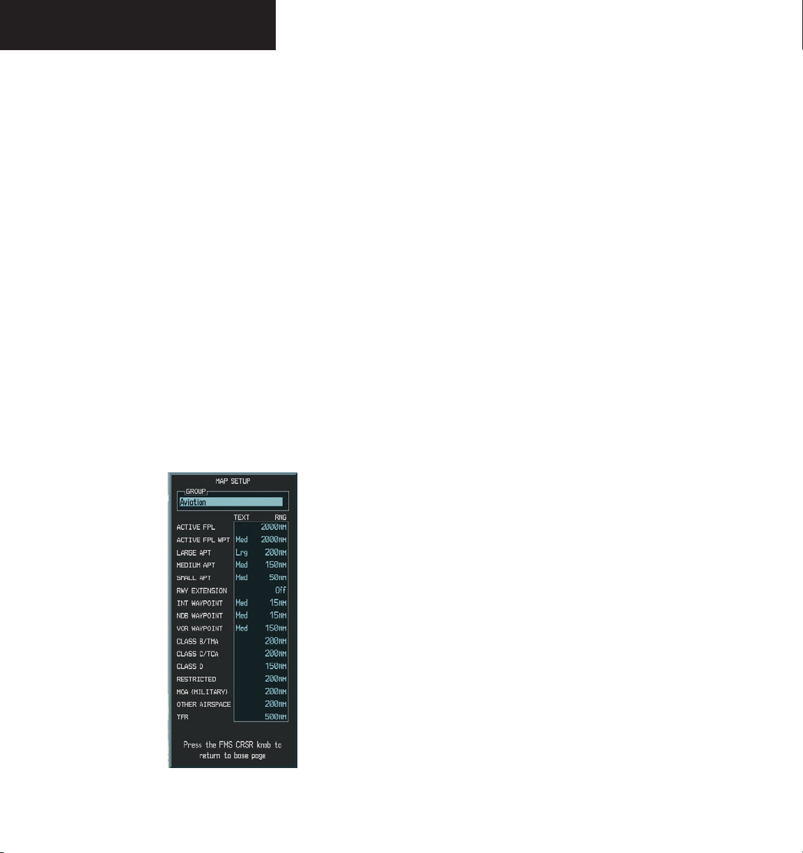
• Large, Medium, and Small Airports (LARGE APT,
MEDIUM APT, SMALL APT) - The airport label size sets
the size at which the large, medium, or small airport
names size appear on the display. The zoom range sets
the maximum range at which the airports appear on the
display:
• Large: off - 500 nm
• Medium: off - 300 nm
• Small: off - 100 nm
• Intersection, Non-Directional Beacon, and VOR
Waypoints (INT WAYPOINT, NDB WAYPOINT, VOR
WAYPOINT) - The INT, NDB, and VOR label size sets the
maximum range at which the navaids names appear on
the display. The zoom range sets the maximum range at
which the navaids appear on the display:
• INT: off - 30 nm
• NDB: off - 30 nm
• VOR: off - 300 nm
FMS
7. Press the
knob to return to the Navigation
Map Page.
Aviation Group Options
• Active Flight Plan (ACTIVE FPL)- the active flight
plan zoom range sets the maximum range at which the
active flight plan magenta line is displayed on the display
(off - 2000 nm).
• Active Flight Plan Waypoint (ACTIVE FPL WPT)the active flight plan waypoint label size sets the size at
which the active flight plan names appear on the display
(none, small, medium, and large). The zoom range sets
the maximum range at which active flight plan waypoints
appear on the display (off - 2000 nm).
Garmin G1000 MFD Pilot’s Guide for the Beechcraft A36/G36190-00574-00 Rev. A
8-27
Page 30
NAVIGATION MAP PAGE
• Airspace Boundaries (CLASS B/TMA, CLASS C/TCA,
and CLASS D) - The airspace zoom range sets the maximum
range at which the three classes of airspace appear on the
display. The zoom range sets the maximum range at which
the airspace boundaries appear on the display:
• CLASS B: off - 500 nm
• CLASS C: off - 500 nm
• CLASS D: off - 300 nm
• “Other” Airspace Boundaries (RESTRICTED, MOA
(Military), OTHER AIRSPACE, nad TFR (temporary flight
restrictions)- the other airspace boundary zoom range sets
the maximum range at which restricted, MOA, and other
(training, caution, danger, warning and alert areas) air
-
space boundaries are displayed
• RESTRICTED: off - 500 nm
• MOA (MILITARY): off - 500 nm
• OTHER AIRSPACE: off - 500 nm
• TFR; (only present when GDL 69 is installed): off
- 2000 nm
To select an aviation group item range:
1. With the Navigation Map Page displayed, press
the
MENU
key to display the Navigation Map
Page Menu. The cursor flashes on the ‘Map
Setup’ option.
ENT
2. Press the
key. The Map Setup Menu is
displayed.
3. Turn the
group. Press the
small FMS
knob to select the ‘Aviation’
ENT
key. The cursor flashes
on the ‘ACTIVE FPL’ field.
4. Turn the
large FMS
knob to select the desired
option.
5. Turn the
small FMS
knob to select the desired
range.
ENT
6. Press the
key to accept the selected
option.
FMS
7. Press the
knob to return to the Navigation
Map Page.
8-28
Figure 8.2.7 Aviation Group Options
Garmin G1000 MFD Pilot’s Guide for the Beechcraft A36/G36 190-00574-00 Rev. A
Page 31

NAVIGATION MAP PAGE
To select an aviation group item text size:
1. With the Navigation Map Page displayed, press
the
MENU
key to display the Navigation Map
Page Menu. The cursor flashes on the ‘Map
Setup’ option.
ENT
2. Press the
key. The Map Setup Menu is
displayed.
3. Turn the
group. Press the
small FMS
knob to select the ‘Aviation’
ENT
key. The cursor flashes
on the ‘ACTIVE FPL’ field.
4. Turn the
large FMS
knob to select the desired
option.
5. Turn the
small FMS
knob to select the desired
text size.
ENT
6. Press the
key to accept the selected text
size.
FMS
7. Press the
knob to return to the Navigation
Map Page.
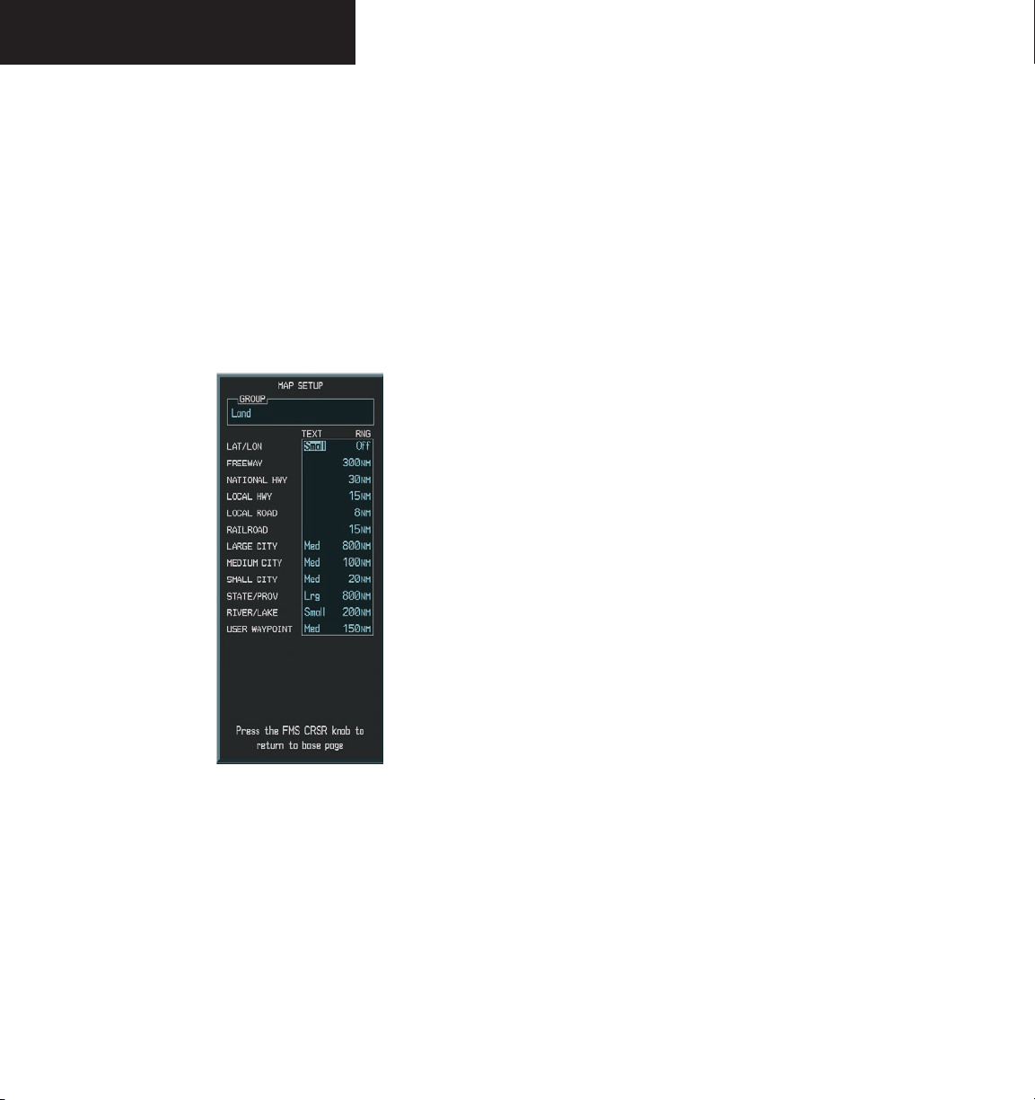
Land Group Options
• Cities and Towns (LARGE CITY, MEDIUM CITY,
SMALL CITY) - The cities and town label size sets the
maximum range at which city and town names appear on
the display. The zoom range sets the maximum range at
which cities and towns appear on the display:
• LARGE CITY (approximate populations greater
than 200,000): off - 1500 nm
• MEDIUM CITY (approximate populations greater
than 50,000): off - 200 nm
• SMALL CITY (approximate populations greater
than 5,000): off - 50 nm
• Latitude/Longitude (LAT/LON) - the LAT/LON label
size sets the size at which latitude/longitude labels appear
on the display (none, small, medium, and large). The
zoom range sets the maximum range at which LAT/LON
waypoints appear on the display (off - 2000 nm).
• Highways, Roads, and Railroads (FREEWAY, LOCAL
HWY, LOCAL ROAD, RAILROAD) - The highway and
road zoom range sets the maximum range at which high
-
ways, roads, and railroads appear on the display:
• FREEWAY: off - 800 nm
• NATIONAL HWY: off - 80 nm
• LOCAL HWY: off - 30 nm
• LOCAL ROAD: off - 15 nm
• RAILROAD: off - 30 nm
Garmin G1000 MFD Pilot’s Guide for the Beechcraft A36/G36190-00574-00 Rev. A
8-29
Page 32
NAVIGATION MAP PAGE
• States and Provinces, Rivers and Lakes, and
User Waypoints (STATE/PROV, RIVER/LAKE, USER
WAYPOINT) - the label range sets the maximum range
at which the three categories appear on the display. The
zoom range sets the maximum range at which the three
categories appear on the display:
• STATE/PROV: off - 1500 nm
• RIVER/LAKE off - 500 nm
• USER WAYPOINT: off - 300 nm
To select a land group item range:
1. With the Navigation Map Page displayed, press
the
MENU
key to display the Navigation Map
Page Menu. The cursor flashes on the ‘Map
Setup’ option.
ENT
2. Press the
key. The Map Setup Menu is
displayed.
3. Turn the
group. Press the
small FMS
knob to select the ‘Land’
ENT
key. The cursor flashes
on the ‘LAT/LON’ field.
4. Turn the
large FMS
knob to select the desired
option.
5. Turn the
range. Press the
small FMS
knob to select the desired
ENT
key to accept the selected
option.
FMS
6. Press the
knob to return to the Navigation
Map Page.
To select a land group item text size:
1. With the Navigation Map Page displayed, press
the
MENU
key to display the Navigation Map
Page Menu. The cursor flashes on the ‘Map
Setup’ option.
8-30
Figure 8.2.8 Land Group Options
Garmin G1000 MFD Pilot’s Guide for the Beechcraft A36/G36 190-00574-00 Rev. A
2. Press the
displayed.
3. Turn the
small FMS
group. Press the
on the ‘LAT/LON’ field.
4. Turn the
large FMS
option.
5. Turn the
small FMS
text size. Press the
selected option
6. Press the
FMS
Map Page.
ENT
key. The Map Setup Menu is
knob to select the ‘Land’
ENT
key. The cursor flashes
knob to select the desired
knob to select the desired
ENT
key to accept the
knob to return to the Navigation
Page 33

Measure Bearing/Distance
The second map setup option is ‘Measure Bearing/
Distance’ which provides a quick and easy method for
determining the bearing and distance between any two
points on the Navigation Map Page.
NOTE: Pressing the ENT key at any location with
the ‘Measure’ option enabled allows bearing and
distance from the newly selected position to be
acquired.
To measure bearing and distance between
two points:
MENU
1. Press the
Page displayed).
key (with the Navigation Map
NAVIGATION MAP PAGE
2. Turn the
small FMS
knob to highlight the
‘Measure Bearing/Distance’ field and press
the
ENT
key. An on-screen reference pointer
is displayed on the map display at the aircraft’s
present position.
3. Move the joystick to place the reference
pointer at the desired location. The bearing
and distance is displayed at the top of the map
display. Elevation at the current position is also
displayed.
4. To exit the Measure Bearing/Distance option,
push in the joystick or select ‘Stop Measuring’
from the page menu options.
Garmin G1000 MFD Pilot’s Guide for the Beechcraft A36/G36190-00574-00 Rev. A
8-31
Page 34
NAVIGATION MAP PAGE
Bearing,
Distance, and
Elevation
Information
Reference
Pointer
Figure 8.2.9 Measuring Bearing and Distance
Pointer
Latitude and
Longitude
8-32
Garmin G1000 MFD Pilot’s Guide for the Beechcraft A36/G36 190-00574-00 Rev. A
Page 35
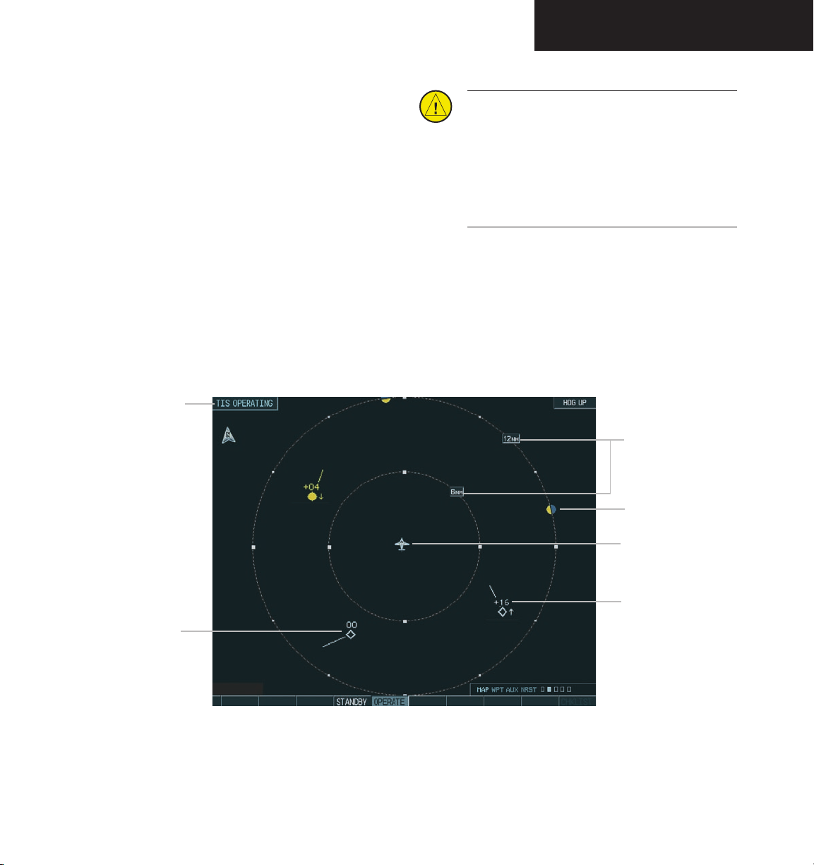
TRAFFIC MAP PAGE
8.3 TRAFFIC MAP PAGE
The Traffic Map Page is the second page in the Map
Group and displays the following information:
• Current aircraft location, surrounding Traffic
Information System (TIS) traffic, and range mark
ing rings.
• The current traffic mode (OPERATE, STANDBY).
• A traffic alert message (FAILED, DATA FAILED,
NO DATA, UNAVAILABLE)
• Traffic display banner (AGE 00:, TRFC COAST,
TA OFF Range, TRFC RMVD, TRFC FAIL, NO
TRFC DATA, TRFC UNAVAIL, TRAFFIC)
Traffic Mode
CAUTION: Use of the Traffic Map to maneuver
the airplane to avoid traffic is prohibited. The
Traffic Information System (TIS) is intended
for advisory use only. TIS is intended only to
help the pilot to visually locate traffic. It is the
-
responsibility of the pilot to see and maneuver
to avoid traffic.
To select the Traffic Map Page:
1. Select the MAP group of pages. Turn the
FMS
knob to the right to select the Traffic Map
small
Page.
Map Range
Traffic, Out of
Range
Traffic
Own Aircraft
Proximate,
Known Altitude
Figure 8.3.1 Traffic Map Page
Garmin G1000 MFD Pilot’s Guide for the Beechcraft A36/G36190-00574-00 Rev. A
8-33
Page 36

TRAFFIC MAP PAGE
TIS SYMBOLOGY
TIS traffic is displayed on the Traffic Map Page
according to TCAS symbology. A Traffic Advisory (TA)
symbol is displayed as a solid yellow circle (or half circle
on the outer range ring if the traffic is outside the range
of the dedicated traffic page). All other traffic is displayed
as a hollow white Beechcraft. Altitude deviation from the
user’s aircraft altitude is displayed above the target symbol
if they are above own aircraft altitude, and below the
symbol if they are below own aircraft altitude. Altitude
trend is displayed as an up arrow (+500 ft/min), down
arrow (-500 ft/min), or no symbol if less than 500 ft/min
rate in either direction. Other symbols:
• Other Traffic – this symbol represents traffic
detected within the selected display range that
does not generate a TA.
• Traffic Advisory (TA) – this symbol is generated
when traffic meets the advisory criteria described
previously.
• Traffic Ground Track is indicated on the Traffic
Map Page by a “target track vector”. The track
vector line is projected from the traffic advisory
symbol and is drawn at any angle necessary to
represent the current track of the traffic advisory
data.
NOTE: Traffic Information Service (TIS) is not
available in all areas.
TRAFFIC MAP PAGE OPERATIONS
Power-Up Test
The TIS interface performs an automatic test during
power-up. If the system passes the power-up test, the
standby screen is displayed on the Traffic Map Page. If the
system passes the power-up test, and the aircraft is
airborne, traffic is displayed on the Traffic Page in the
operating mode.
If the system fails the power up test, the ‘NO DATA’,
‘DATA FAILED’, or ‘FAILED’ message is displayed.
Contact your Beechcraft service center or Garmin dealer
for corrective action if the ‘DATA FAILED’, or ‘FAILED’
message is displayed. The ‘FAILED’ message indicates
the GTX 33 transponder has failed. The ‘DATA FAILED’
message indicates data is being received from the GTX 33
but a failure was detected in the data stream. The ‘NO
DATA’ message indicates that data is not being received
from the GTX 33.
Changing the Map Range
To change the map range:
1. Turn the
turn the joystick counter-clockwise to zoom
in. Map ranges are 2 nm, 6 nm, and 12 nm.
joystick clockwise to zoom out, or
8-34
NOTE: See Appendix F for traffic symbol descriptions.
Garmin G1000 MFD Pilot’s Guide for the Beechcraft A36/G36 190-00574-00 Rev. A
Page 37

TRAFFIC MAP PAGE
Operating Mode
Once the aircraft is airborne (determined by system
configuration at the time of installation) the system
switches from standby mode to operating mode. The
G1000 displays ‘OPERATE’ in the upper left hand corner
of the display and begins to display traffic on the Traffic
or Map Page. The TIS Traffic Advisory (TA) should
alert the crew to use additional vigilance to identify the
intruding aircraft. Any time the traffic symbol becomes
a yellow circle or a voice warning is announced, conduct
a visual search for the intruder. Maintain visual contact
to ensure safe operation.
Once the aircraft is on the ground (determined by
system configuration at the time of installation) the
system switches from operating mode to standby mode. The
Traffic Map Page displays ‘STANDBY’.
• STANDBY – when the Traffic Map Page displays
‘STANDBY’ in the status box located in the upper
left corner of the Traffic Map Page, the TIS system
is in standby mode and cannot display traffic data.
• OPERATE – when the Traffic Map Page displays
‘OPERATE’ in the status box located in the left
corner of the Traffic Map Page, the TIS system
is in operational mode and available to display
traffic on the Traffic or Map Page.
MENU
3. Press the
key. The page menu is
displayed with ‘Standby Mode’ or ‘Operate
Mode’ highlighted. Press the
ENT
key on the
desired selection.
TIS Audio Alert
A TIS audio alert is generated whenever the number
of TAs on the Traffic Map Page display increases from one
scan to the next. The limiting to TAs only reduces the
amount of “nuisance” alerting due to proximate aircraft.
For example, when the first TA is displayed, the pilot is
alerted audibly. So long as a single TA aircraft remains on
the TIS display, no further audio alert is generated. If a
second (or more) TA aircraft appear on the display, a new
audio alert is sounded. If the number of TAs on the TIS
display decreases and then increases, a new audio alert is
sounded. The TIS audio alert is also generated whenever
TIS service becomes unavailable. The volume of the audio alert (including the choice between a male or female
voice) is configured during installation. The following
TIS audio alerts are available:
• “Traffic” - TIS traffic alert is received.
• “Traffic Not Available” - TIS service is not available
or out of range.
The pilot can switch between the standby (STBY) and
operate (ON) modes of operation to manually override
automatic operation using the page menu or softkeys.
To switch between operating modes:
MODE
1. Press the
2. Press the
softkey.
STBY
or ON softkey to switch between
modes. ‘STANDBY’ or ‘OPERATE’ is displayed
in the status box located in the upper left
corner of the Traffic Map Page OR:
Garmin G1000 MFD Pilot’s Guide for the Beechcraft A36/G36190-00574-00 Rev. A
8-35
Page 38

TRAFFIC MAP PAGE
TIS Traffic Status
The MFD indicates the following TIS traffic status to
the pilot.
Traffic Banner
• AGE - if traffic data is not refreshed within 6
seconds, an age indicator (i.e., ‘AGE 00:06’) is
displayed in the lower left corner of the display
(when displaying traffic). After another 6
seconds, if data is still not received, the traffic
is removed from the display. The pilot should
be aware that the quality of displayed traffic is
reduced in this condition.
• TRFC COAST - the ‘TRFC COAST’ (traffic
coasting) banner located above the AGE timer
indicates that displayed traffic is held even though
the data is stale. The pilot should be aware that
the quality of displayed traffic is reduced in this
condition.
• TRFC RMVD - the ‘TRFC RMVD’ banner indicates
that traffic has been removed from the display due
to the age of the data being too old to “coast” (for
the time period of 12-60 seconds from the last
receipt of a TIS message). The pilot should be
aware that traffic may be present but not shown.
• TA OFF - the ‘TA OFF’ scale banner displayed in
the lower left corner of the display indicates that
a traffic advisory is outside the selected display
range. The traffic advisory off range banner is
removed when the traffic advisory is within the
selected display range.
• TRAFFIC - on the PFD, when the system receives
a traffic advisory a flashing ‘TRAFFIC’ alert is
displayed in the upper left hand portion of the
display. The PFD inset map also automatically
displays traffic data.
8-36
Garmin G1000 MFD Pilot’s Guide for the Beechcraft A36/G36 190-00574-00 Rev. A
Page 39
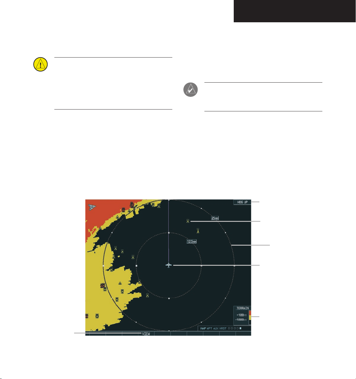
TERRAIN PROXIMITY PAGE
8.4 TERRAIN PROXIMITY PAGE
CAUTION: Use of Terrain Proximity information for primary terrain avoidance is prohibited.
The Terrain Proximity Map is intended only to
enhance situational awareness. It is the pilot’s
responsibility to provide terrain avoidance at all
times.
The Terrain Proximity Page displays the following:
• Current aircraft location
• Range marking rings (25 nm, 25/50 nm, 50/100
nm, and 100/200 nm)
• Heading Box (North Up, Track Up, DTK Up,
HDG Up). Heading on the Terrain Proximity Page
displays ‘HDG Up’ map data unless there is no
valid heading
• Terrain
• Terrain Range - Indicates the terrain elevation
in colors relative to the aircraft altitude (Figure
8.4.2)
• Obstacles
NOTE: Terrain data is not displayed when the
aircraft latitude is greater than 75 degrees north
or 60 degrees south.
Page Orientation
View Selection
Obstacles
Range Marking Ring
Current Aircraft
Location
Terrain Range
Figure 8.4.1 Terrain Proximity Page
Garmin G1000 MFD Pilot’s Guide for the Beechcraft A36/G36190-00574-00 Rev. A
8-37
Page 40
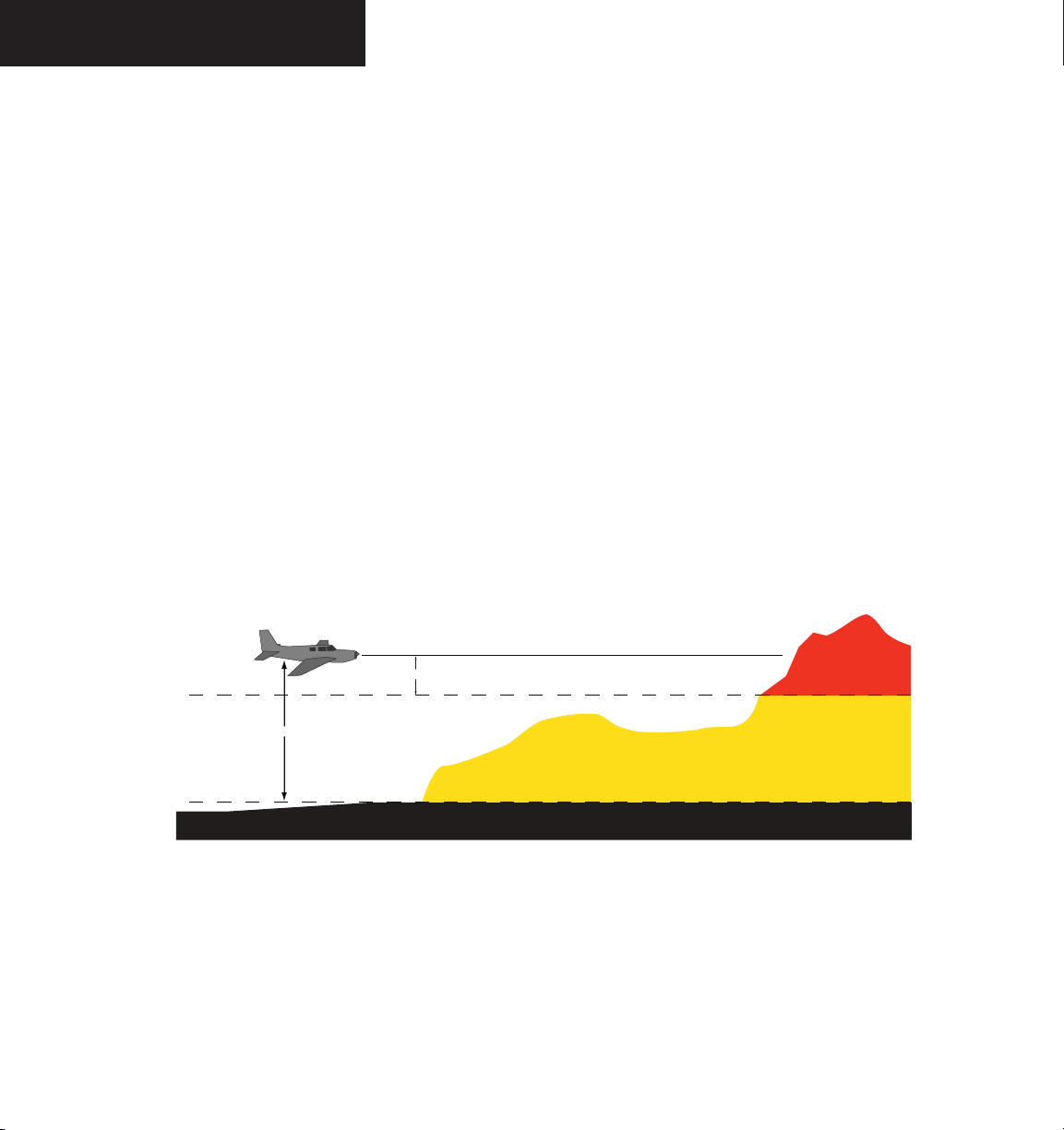
TERRAIN PROXIMITY PAGE
1000' AGL
Aircraft Altitude
100' Threshold
TERRAIN PROXIMITY PAGE OPERATIONS
There are two terrain/obstacle viewing options available
(relative to the position of the aircraft), a radar-like ARC
(120°) display and a 360° default display.
To change the viewing mode between 360°
and ARC:
1. Select the Terrain Proximity Page
VIEW
2. Press the
softkey. Press the
softkey.
3. To return to the 360 degree viewing display
press the 360 softkey OR:
4. Press the MENU key. The page menu is
displayed with ‘View Arc’ or ‘View 360º’
highlighted. Press the
ENT key on the desired
selection.
ARC
To change the map range on the Terrain
Proximity Page:
1. Turn the
the
joystick
joystick
clockwise zoom out or turn
counter-clockwise zoom in. Map
ranges are 25 nm, 25/50 nm, 50/100 nm, and
100/200 nm.
8-38
Figure 8.4.2 Terrain Scale
Garmin G1000 MFD Pilot’s Guide for the Beechcraft A36/G36 190-00574-00 Rev. A
Page 41

TERRAIN PROXIMITY PAGE
DISPLAYING OBSTACLE DATA
The Terrain Proximity Page displays obstacle data
with heights greater than 200 feet Above Ground Level
(AGL) located at their geographical position location throughout the world. Obstacles are displayed
in three levels. The G1000 will adjust colors on the
Terrain Proximity Page automatically as the aircraft
altitude changes. The display color patterns are as
follows:
• SAFE
• CAUTION
• WARNING
GRAY-Safe
Obstacle data is displayed in gray when the
obstacle height (MSL) is greater than 1000 feet below
the current aircraft altitude.
YELLOW-Caution
Obstacle data is displayed in yellow when the
obstacle height is 100 feet below MSL the current
aircraft altitude to 1000 feet below the current aircraft
altitude.
RED-Critical
Navigation Map Display Conditions
The Map Setup Page Menu has ‘OBSTACLE’ and
‘TERRAIN feature On/Off options. The Terrain Proximity
Page displays or does not display obstacles on the Navigation Map Page based on the selection of each as summarized in the table below:
TERRAIN
FEATURE
OFF OFF NO OBSTACLES
OFF ON SAFE, CAUTION, AND
ON OFF CAUTION AND
ON ON SAFE, CAUTION, AND
Note: Obstacles are only displayed at certain
map zoom ranges, on certain map fields, and
will only be displayed if an obstacle database is
loaded on the SD card.
OBSTACLE
FEATURE
TERRAIN
PROXIMITY PAGE
DISPLAYED
WARNING OBSTACLES
DISPLAYED
WARNING OBSTACLES
DISPLAYED
WARNING OBSTACLES
DISPLAYED
Obstacle data is displayed in red when the obstacle
height is at or above 100 feet Mean Sea Level (MSL)
below the current aircraft altitude.
Obstacle Shapes
Obstacle shapes and defining criteria are found in
Appendix F.
Garmin G1000 MFD Pilot’s Guide for the Beechcraft A36/G36190-00574-00 Rev. A
Note: The table above is only for the Navigation
Map Page. The Terrain Proximity Page always
shows ONLY caution and warning obstacles.
8-39
Page 42

TERRAIN PROXIMITY PAGE
This page intentionally left blank.
8-40
Garmin G1000 MFD Pilot’s Guide for the Beechcraft A36/G36 190-00574-00 Rev. A
Page 43

DIRECT-TO NAVIGATION
8.5 DIRECT-TO NAVIGATION
The “Direct-to” function provides a quick method
of setting a course to a destination waypoint. Once a
Direct-to is activated, the G1000 establishes a point-topoint course line from the present position to the selected
Direct-to destination. If the course change is greater than
30 degrees, a course extension is offset from the present
position to allow a standard rate turn to intercept the
Direct-to course line. Note that the CDI (HSI) needle will
not be immediately centered in this case. Direct-to course
guidance is provided until the Direct-to is cancelled or
replaced by a new destination, and the navigation data is
displayed on the Navigation Map Page
Identifier
Facility Name
City
Flight Plan Field
Map of the
Selected
Waypoint
Bearing
Distance
Direct-to
Course
Symbol
Nearest Airport
Map Orientation
Map Range
Region
Latitude/
Longitude
Activate Field
To select a Direct-to destination:
1. Press the
Direct-to
key. The Direct-to page
is displayed with the destination field highlighted.
2. Turn the
small FMS
knob to enter the first letter
of the destination waypoint identifier. The
destination waypoint may be an airport, VOR,
NDB, intersection or user waypoint, as long as
it is in the database or stored in memory as a
user waypoint. Turn the
large FMS
knob to the
right to move the cursor to the next character
position.
3. Repeat steps 2 and 3 to spell out the rest of
the waypoint identifier.
ENT
4. Press the
key to confirm the identifier. The
‘Activate?’ field is highlighted.
ENT
5. Press the
key to activate a Direct-to course
to the selected destination.
If navigating to a waypoint and the aircraft moves off
course, the Direct-to feature can be used to re-center the
CDI (HSI) needle and proceed to the same waypoint.
To re-center the CDI (HSI) needle to the
same destination waypoint:
1. Press the Direct-to key, followed by press
ENT
ing the
key twice. NOTE: If navigating
-
an approach with the missed approach point
(MAP) as the current destination, re-centering
the CDI (HSI) needle with the Direct-to key
cancels the approach.
Figure 8.5.1 Direct-to Page
Garmin G1000 MFD Pilot’s Guide for the Beechcraft A36/G36190-00574-00 Rev. A
8-41
Page 44

DIRECT-TO NAVIGATION
DIRECT-TO NAVIGATION OPERATIONS
Selecting a Direct-to Waypoint
In addition to selecting a Direct-to waypoint using
an identifier, a Direct-to waypoint can be selected in the
following ways:
• by facility or city name
• from the active flight plan
• from the nearest airports list
• from a waypoint field, waypoint page, or map
highlight shortcut
Selecting a Direct-to Destination by Facility or City Name
In addition to selecting a destination by identifier, the
Direct-to Page also allows the selection of airports, VORs
and NDBs by facility or city name. If duplicate entries
exist for the entered facility or city name, additional entries
can be viewed by continuing to turn the small FMS knob
during the selection process.
To select a Direct-to destination by facility
name or city:
1. Press the
Direct-to
key. The Direct-to Page is
displayed with the waypoint identifier field
highlighted.
2. Turn the
large FMS
knob to highlight the facility
or city name field.
3. Turn the
small and large FMS
knob to enter
the facility or city location of the desired
waypoint.
NOTE: the “Spell N Find” feature selects the first
entry in the database based on the characters
that have been entered to that point.
4. Continue turning the
through any additional database listings for
the selected facility name or city. The
FMS
knob can be used to scroll backwards if
small FMS
knob to scroll
small
the desired waypoint was passed up.
8-42
ENT
5. Press the
waypoint, and
key to confirm the selected
ENT
again to activate a Direct-
to.
Garmin G1000 MFD Pilot’s Guide for the Beechcraft A36/G36 190-00574-00 Rev. A
Page 45

DIRECT-TO NAVIGATION
Selecting a Direct-to Destination from the Active Flight Plan
Any waypoint contained in the flight plan may be
selected as a Direct-to destination from the Direct-to
Waypoint Page when navigating an active flight plan.
To select a Direct-to destination from the
active flight plan:
1. Press the
Direct-to
key. The Direct-to Waypoint
Page is displayed with the waypoint identifier
field highlighted.
2. Turn the
large FMS
knob to highlight the flight
plan ‘FPL’ field.
3. Turn the
small FMS
knob to display a window
showing all waypoints in the active flight
plan.
4. Continue turning the
small FMS
knob to scroll
through the list and highlight the desired
waypoint.
ENT
5. Press the
waypoint, and
key to confirm the selected
ENT
again to activate a Direct-
to.
Figure 8.5.2 Flight Plan Waypoint Direct-to
Garmin G1000 MFD Pilot’s Guide for the Beechcraft A36/G36190-00574-00 Rev. A
8-43
Page 46

DIRECT-TO NAVIGATION
Selecting the Nearest Airport as a Direct-to Destination
The Direct-to Page always displays the nearest airports
(from the present position) on the NRST field.
To select a nearby airport as a Direct-to
destination:
1. Press the
Direct-to
key. The Direct-to Page is dis-
played with the destination field highlighted.
2. Turn the
large FMS
knob to highlight the near-
est airport field.
3. Turn the
small FMS
knob to display a window
showing up to ten nearby airports.
4. Continue turning the
small FMS
knob to scroll
through the list and highlight the desired airport.
ENT
5. Press the
waypoint, and
key to confirm the selected
ENT
again to activate a Direct-
to.
Shortcuts
• The waypoint displayed on the VOR waypoint
page.
• The waypoint displayed on the NDB waypoint
page.
• The waypoint displayed on the intersection
waypoint page.
• The waypoint displayed on the user waypoint
page.
8-44
Shortcuts are available when using the Direct-to key,
allowing the pilot to bypass the use of the FMS knobs.
Any time a waypoint field is highlighted and then the Di-
rect-to key is pressed, the highlighted waypoint will be
the direct-to waypoint.
The following are “candidates” for Direct-to
waypoints:
• The highlighted waypoint when map panning
with the MFD map panning pointer.
• The highlighted waypoint identifier field on any
page.
• The airport waypoint page airport when on
the airport information, arrival, departure, or
approach pages.
Garmin G1000 MFD Pilot’s Guide for the Beechcraft A36/G36 190-00574-00 Rev. A
Figure 8.5.3 Nearest Airport Direct-to
Page 47

DIRECT-TO NAVIGATION
Canceling Direct-to Navigation
Once a Direct-to is activated, the G1000 provides
navigation guidance to the selected destination until the
Direct-to is either replaced with a new Direct-to or flight
plan, or cancelled, or if the unit is turned off.
To cancel a Direct-to:
1. Press the
Direct-to
Page.
2. Press the
MENU
options menu.
3. With ‘Cancel Direct-To NAV’ highlighted, press
the
ENT
key. If a flight plan is still active, the
G1000 resumes navigating the flight plan
along the closest leg.
key to display the Direct-to
key to display the Direct-to
Specifying a Course to a Waypoint
During a Direct-to, the G1000 sets a direct great circle
course to the selected destination. The course to the
destination, using the course field on the Direct-to Page
can be manually defined.
To manually define the Direct-to course:
1. Press the
2. Turn the
Direct-to
small and large FMS
the destination waypoint.
3. Press the
ENT
waypoint, then turn the
highlight the course field.
4. Turn the
small and large FMS
the desired course and press the
5. Press the
ENT
using the selected destination and course.
key.
knobs to select
key to confirm the selected
large FMS
knob to
knobs to select
ENT
key.
key again to begin navigation
Figure 8.5.4 Canceling Direct-to Navigation
Garmin G1000 MFD Pilot’s Guide for the Beechcraft A36/G36190-00574-00 Rev. A
Figure 8.5.5 Manual Course Direct-to
8-45
Page 48

DIRECT-TO NAVIGATION
This page intentionally left blank.
8-46
Garmin G1000 MFD Pilot’s Guide for the Beechcraft A36/G36 190-00574-00 Rev. A
Page 49

FLIGHT PLANS
8.6 FLIGHT PLANS
The G1000 can create up to 99 different flight plans
with up to 31 waypoints in each flight plan. The flight
plan (FPL) page group consists of three pages:
• Active Flight Plan
• Flight Plan Catalog
• Vertical Navigation
The Flight Plan Pages are used to create, edit and copy
flight plans. The Vertical Navigation Page is used to create
a three-dimensional profile which guides the aircraft to a
final (target) altitude at a specified location.
ACTIVE FLIGHT PLAN PAGE
The Active Flight Plan Page provides information
and editing functions for the flight plan currently in
use for navigation. Once a Direct-to or flight plan has
been activated, the Active Flight Plan Page shows the
following:
• Each waypoint for the flight plan (or a single
waypoint for a Direct-to), along with the desired
track (DTK) and distance of each leg (DIS).
• Active leg information with enroute safe altitude
(ESA) for the specified leg.
• Active FPL information with enroute safe altitude
(ESA)
• Flight plan information showing remaining leg
and remaining total distance, and enroute safe
altitude for the entire route.
The data fields are user-selectable and can be changed
to display the following:
• Cumulative Distance (CUM)
• Distance (DIS)
• Desired Track (DTK)
• Enroute Safe Altitude (ESA)
• Estimated Time of Arrival (ETA)
• Estimated Time Enroute (ETE)
ACTIVE FLIGHT PLAN PAGE OPTIONS
The following options are available for the Flight Plan
Page:
• Activate Leg
• Store Flight Plan
• Invert Flight Plan
• Delete Flight Plan
• Load Departure
• Load Arrival
• Load Approach
• Remove Arrival
• Remove Departure
• Remove Approach
• Closest Point of FPL
• Change Fields
• Restore Defaults
Garmin G1000 MFD Pilot’s Guide for the Beechcraft A36/G36190-00574-00 Rev. A
8-47
Page 50
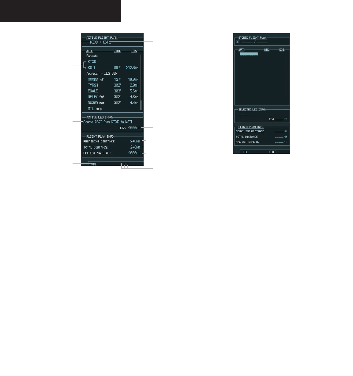
FLIGHT PLANS
Departure Airport
Identifier
Active Leg
Active Leg
Information
Flight Plan
Page Group
Figure 8.6.1 Active Flight Plan Page
Destination
Airport
Identifier
Estimated Safe
Altitude
Flight Plan
Information
Active Flight
Plan Page
Figure 8.6.2 New Flight Plan
Create a New Flight Plan
‘Create New Flight Plan’ creates a new flight plan.
To create a new flight plan:
FPL
1. Press the
key and turn the
to display the Flight Plan Catalog Page.
small FMS
knob
8-48
MENU
2. Press the
key to display the Flight Plan
Catalog Page options.
3. Turn the
large FMS
New Flight Plan’ and press the
knob to highlight ‘Create
ENT
key.
4. A blank flight plan page appears for the first
empty storage location. Turn the small and
large FMS
departure waypoint and press the
knobs to enter the identifier of the
ENT
key.
5. Repeat step number 4 to enter the identifier
for each additional flight plan waypoint.
6. Once all waypoints have been entered, press
FMS
the
knob to return to the Flight Plan
Catalog Page.
Garmin G1000 MFD Pilot’s Guide for the Beechcraft A36/G36 190-00574-00 Rev. A
Page 51
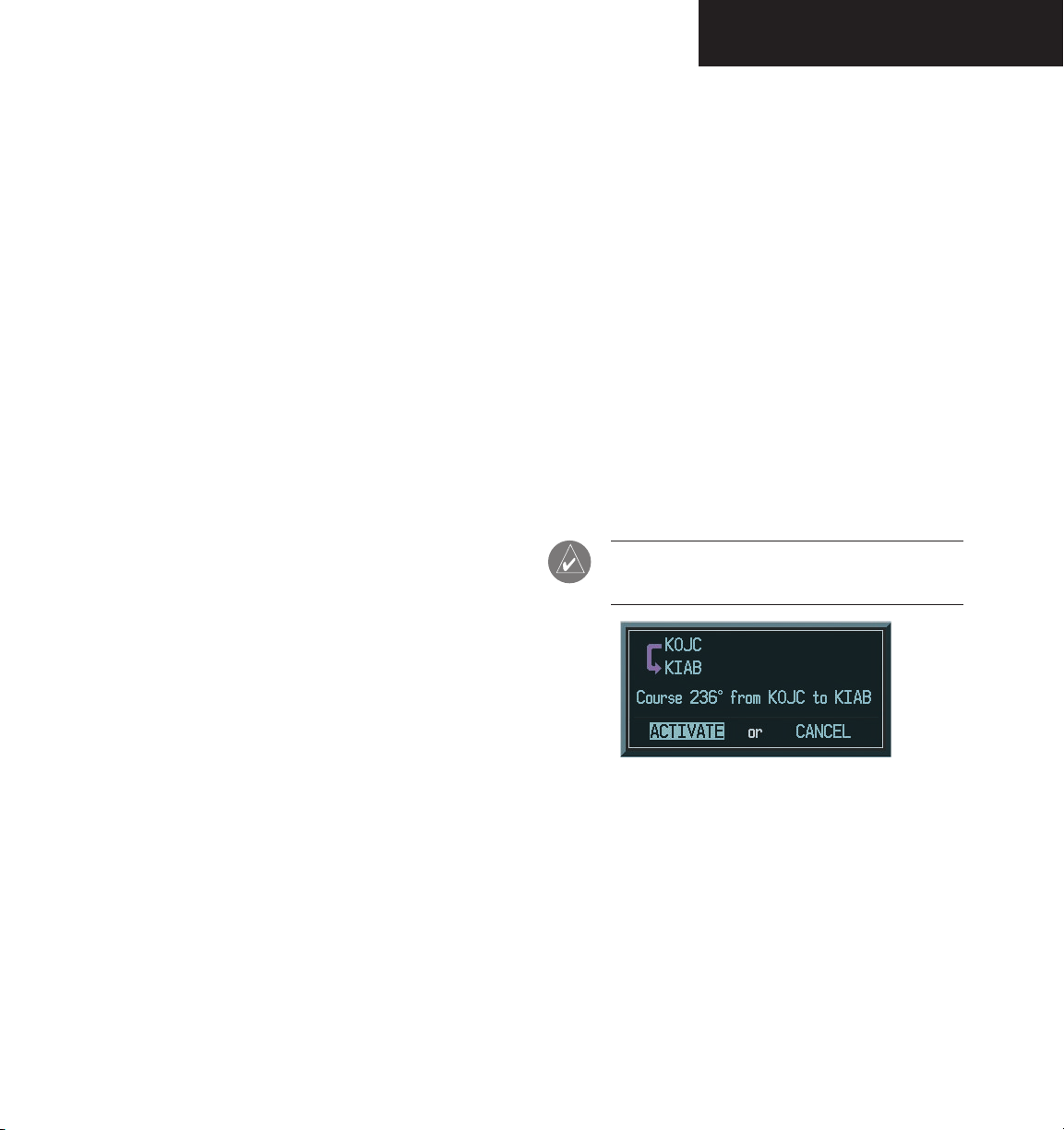
FLIGHT PLANS
To edit a flight plan:
1. Press the
key and turn the
small FMS
knob
FPL
to display the Flight Plan Catalog Page.
2. Press the
3. Turn the
FMS knob
large FMS
desired flight plan and press the
to activate the cursor.
knob to highlight the
ENT
key.
4. To add a waypoint to the flight plan: Turn the
large FMS
knob to select the point where the
new waypoint is to be added. (If an existing
waypoint is highlighted, the new waypoint is
placed directly in front of this waypoint.) Turn
the small and
large FMS
knobs to enter the
identifier of the new waypoint and press the
ENT
key.
5. To delete a waypoint from the flight plan: Turn
large FMS
the
to delete and press the
knob to select the waypoint
CLR
key to display a
remove waypoint confirmation window. With
ENT
‘OK’ highlighted, press the
key to remove
the waypoint. To cancel, turn the large FMS
knob to highlight ‘CANCEL’ and press the ENT
key.
Activate Leg
Activate Leg selects the highlighted leg as the “active
leg” (the flight plan leg which is currently used for
navigation guidance).
To activate a flight plan along a specific
leg:
1. From the Active Flight Plan Page, press the
knob to activate the cursor and turn the
FMS
knob to highlight the desired destination
waypoint.
MENU
2. Press the
key, select the ‘Activate Leg’
option from the page menu and press the
key.
3. A confirmation window is displayed. With
‘Activate’ highlighted, press the
NOTE: The leg can also be activated by pressing
the
ACT LEG
softkey.
ENT
FMS
large
ENT
key.
6. Once all changes have been made, press the
FMS knob
to return to the Flight Plan Catalog
Page.
Garmin G1000 MFD Pilot’s Guide for the Beechcraft A36/G36190-00574-00 Rev. A
Figure 8.6.3 Activate Flight Plan Leg Confirmation
8-49
Page 52

FLIGHT PLANS
Store Flight Plan
Whenever an approach, departure or arrival is loaded
into the active flight plan, a set of approach, departure
or arrival waypoints is inserted into the flight plan along
with a header line describing the instrument procedure
the pilot selected. The original enroute portion of the
flight plan remains active (unless an instrument procedure
is activated) which may be done when the procedure is
loaded or at a later time. Flight plans can also be stored
with an approach, departure or arrival. The active flight
plan is erased when the system is turned off and overwritten when another flight plan is activated.
When storing flight plans with an approach, departure
or arrival, the G1000 uses the waypoint information from
the current database to define the waypoints. If the da
tabase is changed or updated, the G1000 automatically
updates the information if the procedure has not been
modified. If an approach, departure or arrival procedure
is no longer available, the procedure is deleted from the
flight plan and an alert is displayed.
-
To store an existing flight plan:
1. From the Flight Plan Page, press the
to activate the cursor.
2. Turn the
large FMS
desired flight plan and press the
knob to highlight the
MENU
display the Flight Plan Page options.
3. Turn the
large FMS
Flight Plan’ and press the
knob to highlight ‘Store
ENT
key. The flight
plan is stored in the next available position in
the flight plan list on the Flight Plan Catalog
Page.
4. With ‘OK’ highlighted, press the
ENT
store the flight plan.
Figure 8.6.4 Store Flight Plan Confirmation
FMS knob
key to
key to
8-50
Garmin G1000 MFD Pilot’s Guide for the Beechcraft A36/G36 190-00574-00 Rev. A
Page 53

FLIGHT PLANS
Invert Flight Plan
‘Invert Fight Plan’ reverses the active flight plan. After
traveling along a flight plan, the route can be reversed for
navigation guidance back to the original departure point.
To invert and (activate) an existing flight
plan:
FMS
ENT
knob
key to
key to
1. From the Flight Plan Page, press the
to activate the cursor.
2. Turn the
large FMS
desired flight plan and press the
knob to highlight the
MENU
display the Flight Plan Page options.
3. Turn the
large FMS
Flight Plan’ and press the
knob to highlight ‘Invert
ENT
key. The original flight plan remains intact in its flight plan
catalog storage location.
4. With ‘OK’ highlighted, press the
invert the flight plan.
Delete a Waypoint
To delete a waypoint from an existing flight
plan:
FPL
1. Press the
key and turn the
to display the Flight Plan Catalog Page.
FMS
2. Press the
3. Turn the
knob to activate the cursor.
large FMS
knob to highlight the
desired flight plan and press the
4. Turn the
large FMS
knob to select the waypoint
to delete and press the
‘REMOVE WAYPOINT’ confirmation window.
5. With ‘OK’ highlighted, press the
remove the waypoint. To cancel the delete
request, turn the
large FMS
‘CANCEL’ and press the
6. Once all changes have been made, press the
FMS
knob to return to the Flight Plan Page.
small FMS
ENT
key.
CLR
key to display a
ENT
knob to highlight
ENT
key.
knob
key to
Figure 8.6.5 Invert Flight Plan
Figure 8.6.6 Invert Flight Plan Confirmation
Garmin G1000 MFD Pilot’s Guide for the Beechcraft A36/G36190-00574-00 Rev. A
Figure 8.6.7 Remove Waypoint Confirmation
8-51
Page 54
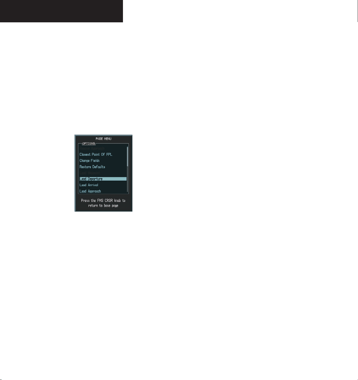
FLIGHT PLANS
Load a Departure
‘Load Departure’ allows a published departure
procedure for the departure airport to be loaded into a
flight plan. It also replaces the current departure with a
new selection. When using a Direct-to, the G1000 uses
the nearest airport as a reference when displaying available
departures. A departure can also loaded using the PROC
key or by pressing the LD DP softkey.
Figure 8.6.8 Loading Departure Options
To select a departure procedure for the
departure airport:
1. From the Active Flight Plan Page, press the
MENU
key to display the Active Flight Plan Page
options.
2. Highlight ‘Load Departure’ from the list and
press the
ENT
key.
3. A window is displayed listing the available
departures for the departure airport. Turn the
FMS knob to select the desired departure and
press the
ENT
key.
4. A window may appear listing runways for the
FMS
departure. Turn the
desired runway and press the
knob to select the
ENT
key. This
window is not displayed for every departure.
5. A second window is displayed listing avail
able transitions for the departure. Turn the
FMS knob to highlight the desired transition
ENT
waypoint and press the
6. With ‘LOAD’ highlighted, press the
key.
ENT
key.
The departure flight plan is displayed as part
of the overall flight plan and is placed in front
of the enroute flight plan.
-
8-52
Garmin G1000 MFD Pilot’s Guide for the Beechcraft A36/G36 190-00574-00 Rev. A
Page 55

Load an Arrival
‘Load Arrival’ allows a published standard terminal
arrival route (STAR) for the destination airport to be
loaded into a flight plan. It also replaces the current arrival
with a new selection. An arrival can also be loaded using
the PROC key or by pressing the LD STAR softkey.
To select an arrival for a Direct-to or flight
plan destination airport:
1. From the Active Flight Plan Page, press the
MENU
key to display the Active Flight Plan Page
options.
2. Highlight the ‘Load Arrival’ option and press
the
ENT
key.
3. A window is displayed listing the available
arrivals for the destination airport. Turn the
FMS knob to select the desired arrival and
press the
ENT
key.
FLIGHT PLANS
4. A second window is displayed listing available
transitions for the arrival. Turn the FMS knob to
highlight the desired transition waypoint and
press the
ENT
key.
5. A third window is displayed listing available
arrival runways. Turn the FMS knob to highlight
ENT
the desired runway and press the
6. With ‘LOAD’ highlighted, press the
key.
ENT
key.
The arrival flight plan is displayed as part of
the overall flight plan and is placed after the
enroute flight plan.
Garmin G1000 MFD Pilot’s Guide for the Beechcraft A36/G36190-00574-00 Rev. A
Figure 8.6.9 Selecting an Arrival
8-53
Page 56
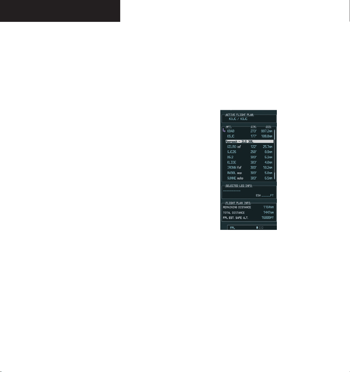
FLIGHT PLANS
Load an Approach
‘Load Approach’ allows for the selection of a published
instrument approach for the destination airport. It also
replaces the current approach with a new selection. In
many cases, it is more convenient to select approaches using the PROC key, or by pressing the LD APR softkey.
To select an approach for a Direct-to or
flight plan destination airport:
1. From the Active Flight Plan Page, press the
MENU
key to display the Active Flight Plan Page
options.
2. Highlight the ‘Load Approach’ option and press
the
ENT
key.
3. A window is displayed listing the available
approaches for the destination airport. Turn the
FMS knob to highlight the desired approach
and press the
4. A second window is displayed listing avail
able transitions for the approach. Turn the
FMS knob to highlight the desired transition
waypoint and press the
option assumes the pilot will receive vectors to
the final course segment of the approach and
will provide navigation guidance to intercept
this final course.)
ENT
key.
ENT
key. (The vectors
-
This allows for the original flight plan to continue
navigating until cleared for the approach, but keeps the
approach available for quick activation when needed.
‘Activate’ adds the approach to the flight plan and begins
navigating the approach course.
Figure 8.6.10 Flight Plan with Loaded Approach
8-54
5. Turn the
large FMS
or Activate?’ and press the
knob to highlight ‘Load?
ENT
key. ‘Load’
adds the approach to the flight plan without
immediately using the approach for navigation
guidance.
Garmin G1000 MFD Pilot’s Guide for the Beechcraft A36/G36 190-00574-00 Rev. A
Page 57
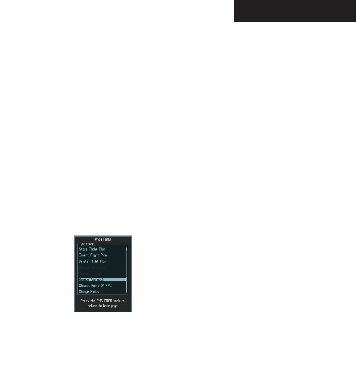
FLIGHT PLANS
Remove a Departure, Arrival, or Approach
• ‘Remove Departure’ deletes the current DP from
the active flight plan.
• ‘Remove Arrival’ deletes the current STAR from
the active flight plan.
• ‘Remove Approach’ deletes the currently selected
approach from the active flight plan.
To remove an approach, arrival or departure from the active flight plan:
1. From the Active Flight Plan Page, press the
MENU
key to display the Active Flight Plan Page
options.
2. Select the ‘Remove Approach’, ‘Remove Arrival’
or ‘Remove Departure’ option and press the
ENT
key.
3. A confirmation window is displayed listing the
procedure the pilot is about to remove. With
ENT
‘OK’ highlighted, press the
the remove request, turn the
to highlight ‘CANCEL’ and press the
key. To cancel
large FMS
ENT
knob
key.
Closest Point of Flight Plan Feature
‘Closest Point of FPL’ calculates the bearing and
closest distance at which a flight plan passes from a
reference waypoint. It can also be used to create a new
user waypoint along the flight plan at the location closest
to a chosen reference waypoint.
To determine the closest point along the
active flight plan to a selected waypoint:
1. From the Active Flight Plan Page, press the
MENU
key to display the Active Flight Plan Page
options.
2. Select the ‘Closest Point of FPL’ option from
the Active Flight Plan Page options and press
the
ENT
key.
3. A window is displayed with the reference
waypoint field highlighted. Turn the small and
large FMS
reference waypoint and press the
4. The G1000 displays the location, lat/lon, bear
ing (BRG), and distance (DIST) to the closest
point along the flight plan from the selected
reference waypoint. To create a user waypoint
at this location and add it to the flight plan,
highlight ‘LOAD’ and press the
name for the new user waypoint is derived from
the identifier of the reference waypoint.
knobs to enter the identifier of the
ENT
key.
ENT
key. The
-
Figure 8.6.11 Removing an Approach
Garmin G1000 MFD Pilot’s Guide for the Beechcraft A36/G36190-00574-00 Rev. A
8-55
Page 58

FLIGHT PLANS
Change Fields
‘Change Fields’ allows for the default fields of DTK
(distance) and DIS (distance) to be changed to one of the
following:
• CUM (cumulative distance)
• DIS (distance)
• DTK (desired track)
• ESA (estimated safe altitude)
• ETA (estimated time of arrival)
• ETE (estimated time enroute)
To change either the DTK or the DIS field:
1. With the Active Flight Plan Page displayed,
MENU
press the
Plan Page options window.
2. Turn the
Fields’ and press the
3. Turn the
or the ‘DTK’ field.
4. Turn the FMS kno
options.
5. Turn the
and press the
remove the cursor.
key to display the Active Flight
large FMS
large FMS
FMS knob to select the desired item
knob to highlight ‘Change
ENT
key.
knob to highlight the ‘DIS’
b
to display a list of
ENT
key. Press the
FMS knob
to
Shortcuts
A number of shortcuts are available to save time when
using the Active Flight Plan Page. These shortcuts speed
the process of removing approaches, departures and
arrivals, and aid in selecting a specific flight plan leg for
navigation guidance.
On the preceding page, options to remove approaches,
departures and arrivals were introduced. This process
may also be completed using the CLR key, as described
below.
To remove an approach, departure or
arrival using the CLR key:
1. With the Active Flight Plan Page displayed,
press the small FMS knob to activate the
cursor.
2. Turn the large FMS knob to highlight the title
for the approach, departure or arrival you wish
to delete. Titles appear in white directly above
the procedure’s waypoints.
3. Press the
window. With ‘OK’ highlighted, press the ENT
key to remove the selected procedure.
This same process may also be used to remove
individual waypoints from the active flight plan.
CLR key to display a confirmation
8-56
Restore Defaults
Restore Defaults returns the ‘DTK’ and ‘DIS’ fields to
‘DTK’ and ‘DIS’.
To restore the DTK and DIS fields on the
Active Flight Plan Page:
1. With the Active Flight Plan Page displayed,
MENU
press the
Plan Page options window.
2. Turn the
Defaults’ and press the
key to display the Active Flight
large FMS
knob to highlight ‘Restore
ENT
key.
Garmin G1000 MFD Pilot’s Guide for the Beechcraft A36/G36 190-00574-00 Rev. A
To remove a waypoint using the CLR key:
1. With the Active Flight Plan Page displayed,
press the small FMS knob to activate the
cursor.
2. Turn the large FMS knob to highlight the iden
tifier for the waypoint you wish to delete.
3. Press the
window.
4. With “OK” highlighted, press ENT to remove
the selected waypoint.
CLR key to display a confirmation
-
Page 59

FLIGHT PLANS
FLIGHT PLAN CATALOG PAGE
The Flight Plan Catalog Page is the second flight planning
page and provides flight planning information and editing
capability. Once a Direct-to or flight plan has been
activated, the Active Flight Plan catalog Page displays the
following:
• Number of flight plans in memory.
• Flight Plan List.
• Flight Plan information box containing departure,
destination, total distance, and estimated safe
altitude information.
To display the Flight Plan Catalog Page:
FPL
1. Press the
key and turn the
to display the Flight Plan Catalog Page.
Flight Plans
in Memory
small FMS
knob
FLIGHT PLAN CATALOG PAGE OPERATIONS
The following operations can be performed from the
Flight Plan Catalog Page:
• Activate a Flight Plan
• Stop Navigating a Flight Plan
• Invert and Activate a FPL
• Create a New Flight Plan
• Copy a Flight Plan
• Delete a Flight Plan
• Delete All Flight Plans
• Sort Flight Plans by Comment
• Flight Plan Catalog Page Options
• Edit a Flight Plan
Flight Plan List
Flight Plan
Information
Figure 8.6.12 Flight Plan Catalog Page
Figure 8.6.13 Flight Plan Catalog Page Options
Garmin G1000 MFD Pilot’s Guide for the Beechcraft A36/G36190-00574-00 Rev. A
8-57
Page 60

FLIGHT PLANS
Activate a Flight Plan
Once a flight plan is defined using the Flight Plan
Catalog Page it can be activated for navigation. Activating
the flight plan overwrites any previous information at that
location.
To activate (begin to navigate) an existing
flight plan:
FPL
1. Press the
key and turn the
to display the Flight Plan Catalog Page.
2. Press the
3. Turn the
FMS knob
large FMS
to activate the cursor.
knob to highlight the
desired flight plan and press the
display the Flight Plan Catalog Page options.
4. Turn the
large FMS
knob to highlight ‘Activate
Flight Plan’ and press the
5. An ‘Activate stored flight plan?’ confirmation
window is displayed. With OK highlighted,
ENT
press the
key to activate the flight plan. To
cancel the flight plan activation, turn the
FMS
knob to highlight ‘CANCEL’ and press the
ENT
key.
small FMS
ENT
key.
MENU
knob
key to
large
Stop Navigating a Flight Plan
To stop navigating a flight plan:
FPL
1. Press the
to display the Flight Plan Catalog Page.
2. Press the
3. Turn the
desired flight plan and press the
display the Flight Plan Catalog Page options.
4. Turn the
Plan’ and press the
Plan’ confirmation window is displayed. With
‘OK’ highlighted, press the
the flight plan. To cancel the flight plan deletion, turn the
‘CANCEL’ and press the
key and turn the
FMS
knob to activate the cursor.
large FMS
knob to highlight the
FMS knob to highlight ‘Delete Flight
ENT
key. A ‘Delete Flight
ENT
large FMS
knob to highlight
ENT
key.
small FMS
MENU
knob
key to
key to delete
8-58
Figure 8.6.14 Activate Stored Flight Plan Confirmation
Garmin G1000 MFD Pilot’s Guide for the Beechcraft A36/G36 190-00574-00 Rev. A
Figure 8.6.15 Delete Flight Plan Confirmation
Page 61

FLIGHT PLANS
Invert and Activate a Flight Plan
‘Invert & Activate FPL’ allows the active flight plan to
be inverted and activated for navigation.
To invert and activate a flight plan:
FPL
1. Press the
key and turn the
to display the Flight Plan Catalog Page.
FMS
2. Press the
3. Turn the
knob to activate the cursor.
large FMS
knob to highlight the
desired flight plan and press the
display the Flight Plan Catalog Page options.
4. Turn the
FMS knob to highlight ‘Invert & Acti-
vate FPL’ and press the
5. An ‘Invert and activate stored flight plan?’ con
firmation window is displayed. With ‘OK’ highlighted, press the
ENT
key to invert and activate
the flight plan. To cancel the operation, turn
the
large FMS
press the
knob to highlight ‘CANCEL’ and
ENT
key.
ENT
small FMS
MENU
key.
knob
key to
Create a New Flight Plan
‘Create New Flight Plan’ creates a new flight plan.
To create a new flight plan:
1. Press the
to display the Flight Plan Catalog Page.
2. Press the
Catalog Page options.
3. Turn the
New Flight Plan’ and press the
4. A blank flight plan page is displayed for the
first empty storage location. Turn the small
and
-
of the departure waypoint and press the
key.
5. Repeat step number 4 to enter the identifier
for each additional flight plan waypoint.
6. Once all waypoints have been entered, press
the
Catalog Page.
FPL
MENU
large FMS
large FMS
FMS
knob to return to the Flight Plan
key and turn the
small FMS
key to display the Flight Plan
knob to highlight ‘Create
ENT
key.
knobs to enter the identifier
knob
ENT
Garmin G1000 MFD Pilot’s Guide for the Beechcraft A36/G36190-00574-00 Rev. A
8-59
Page 62

FLIGHT PLANS
Copy a Flight Plan
‘Copy Flight Plan’ copies the active flight plan to a
Flight Plan Catalog location. The copy function is useful
for duplicating the active flight plan before making
changes.
To copy a flight plan to another flight plan
catalog location:
1. From the Flight Plan Catalog press the
knob to activate the cursor, turn the
FMS
knob to highlight the flight plan the pilot
wishes to copy, then press the
MENU
display the Flight Plan Catalog Options.
2. Turn the
large FMS
Flight Plan’ and press the
knob to highlight ‘Copy
ENT
key.
3. A ‘Copy to flight plan?’ confirmation window
is displayed. With ‘OK’ highlighted, press the
ENT
key to copy the flight plan. To cancel, turn
the
large FMS
press the
knob to highlight ‘CANCEL’ and
ENT
key
FMS
large
key to
Delete a Flight Plan
‘Delete Flight Plan’ removes all waypoints from the
active flight plan. (Deleting a flight plan does not delete the
waypoints contained in the flight plan from the database
or user waypoint memory.) Once the pilot is finished with
a flight plan, it can easily be deleted from the Flight Plan
Catalog Page or the Active Flight Plan Page.
To delete a flight plan from the Active
Flight Plan Page:
1. From the Active Flight Plan Page, press the
MENU
key to display the Active Flight Plan
options window.
2. Turn the
large FMS
Flight Plan’ and press the
3. A ‘Delete all waypoints in flight plan?’ confir
mation window is displayed. With ‘OK’ highlighted, press the
flight plan. To cancel, turn the
to highlight ‘CANCEL’ and press the
To delete a flight plan from the Flight Plan
Catalog Page:
knob to highlight ‘Delete
ENT
key.
ENT
key to delete the active
large FMS
ENT
knob
key.
-
8-60
1. From the Flight Plan Catalog Page, press the
FMS
knob to activate the cursor, turn the
large FMS
knob to highlight the flight plan to
delete.
MENU
2. Press the
key to display the Flight Plan
Catalog options.
3. Turn the
large FMS
Flight Plan’ and press the
knob to highlight ‘Delete
ENT
key.
4. A ‘Delete flight plan?’ confirmation window
is displayed. With ‘OK’ highlighted, press the
ENT
key to delete the flight plan. To cancel,
turn the
and press the
Garmin G1000 MFD Pilot’s Guide for the Beechcraft A36/G36 190-00574-00 Rev. A
large FMS
ENT
knob to highlight ‘CANCEL’
key.
Page 63

FLIGHT PLANS
Delete All Flight Plans
‘Delete All’ removes all flight plans from memory at
one time.
To delete all flight plans:
1. From the Flight Plan Catalog Page, press the
MENU
key to display the Flight Plan Catalog
Page options.
2. Turn the
All’ and press the
large FMS
knob to highlight ‘Delete
ENT
key. A ‘Delete all flight
plans?’ confirmation window is displayed.
With ‘OK’ highlighted, press the
delete all flight plans. To cancel, turn the
FMS
knob to highlight ‘CANCEL’ and press the
ENT
key.
ENT
key to
large
Sort By Comment/Number
‘Sort List By Number/Sort List by Comment’ selects
between a Flight Plan Catalog Page sorted numerically by
the flight plan number or sorted alphanumerically based
upon the comment assigned to each flight plan. When
one option is selected, the other option is displayed on
the Flight Plan Catalog options window.
To sort the catalog listing by number or
comment:
1. From the Flight Plan Catalog Page, press the
MENU
key to display the Flight Plan Catalog
Page options.
2. Turn the
large FMS
By Number’ or ‘Sort List By Comment’ and
press the
ENT
ordering.
knob to highlight ‘Sort List
key. This will change flight plan
3. A ‘Proceed?’ confirmation window is displayed.
With OK highlighted, press the
ENT
key to
change flight plan ordering. To cancel, turn
the
large FMS
press the
knob to highlight ‘CANCEL’ and
ENT
key.
To edit a flight plan:
1. Press the
key and turn the
small FMS
knob
FPL
to display the Flight Plan Catalog Page.
2. Press the
3. Turn the
FMS knob
large FMS
desired flight plan and press the
to activate the cursor.
knob to highlight the
ENT
key.
4. To add a waypoint to the flight plan: Turn the
large FMS
knob to select the point where the
new waypoint is to be added. (If an existing
waypoint is highlighted, the new waypoint is
placed directly in front of this waypoint.) Turn
the small and
large FMS
knobs to enter the
identifier of the new waypoint and press the
ENT
key.
5. To delete a waypoint from the flight plan: Turn
large FMS
the
to delete and press the
knob to select the waypoint
CLR
key to display a
remove waypoint confirmation window. With
‘OK’ highlighted, press the
ENT
key to remove
the waypoint. To cancel, turn the large FMS
knob to highlight ‘CANCEL’ and press the ENT
key.
6. Once all changes have been made, press the
FMS knob
to return to the Flight Plan Catalog
Page.
Garmin G1000 MFD Pilot’s Guide for the Beechcraft A36/G36190-00574-00 Rev. A
8-61
Page 64

FLIGHT PLANS
Graphical Flight Planning Feature
4. If the selected waypoint is not a Jeppesen
The graphical flight planning feature is activated using
the Navigation Map Page and the Active Flight Plan Page.
To create a Point-n-Shoot flight plan:
1. Push the
Joystick
to turn the map cursor on.
5. The pilot can also create and insert a user
2. Select the Active Flight Plan Page and press
FMS
the
knob to highlight the list of waypoints.
Waypoints are inserted ABOVE the highlighted
row if the cursor is on. Waypoints are inserted
at the END of the flight plan if the cursor is
off.
3. To insert waypoints, use the map cursor to
point at the desired waypoint (it will become
visually enhanced when it is properly pointed
to), and press the
LD WPT
softkey. Existing user
waypoints are inserted in the same manner.
waypoint (Airport or Navaid) or user waypoint,
the G1000 creates a user waypoint (beginning
with ‘USR000’) at the point and inserts it into
the flight plan.
waypoint by pointing at a blank spot on the
nav map and pressing ‘LD WPT’. This creates
a user waypoint at the map cursor and inserts
it into the flight plan.
8-62
Garmin G1000 MFD Pilot’s Guide for the Beechcraft A36/G36 190-00574-00 Rev. A
Page 65

VERTICAL NAVIGATION (VNAV) PAGE
The Vertical Navigation Page allows the creation of a
three-dimensional profile which guides the aircraft from
it’s present position and altitude to a final (target) altitude
at a specified location. This is helpful when you would
like to descend to a certain altitude near an airport or
climb to an altitude before reaching a route or Direct-to
waypoint. Once the profile is defined, message alerts and
additional data on the Navigation Map Page keep the pilot
informed of progress.
FLIGHT PLANS
NOTE: An active flight plan or Direct-to must be
entered in order to utilize VNAV.
NOTE: To display terrain or topo data on the Verti-
MAP
cal Navigation Map Page, press the
Press the
the
from the Vertical Navigation Page.
TOPO, TERRAIN, or LTNG
same
softkey to remove the displayed data
softkey.
softkey. Press
To create a vertical navigation profile:
1. Select the Vertical Navigation Page.
FMS
2. Press the
knob to activate the cursor.
Figure 8.6.16 Vertical Navigation (VNAV) Page
Garmin G1000 MFD Pilot’s Guide for the Beechcraft A36/G36190-00574-00 Rev. A
8-63
Page 66
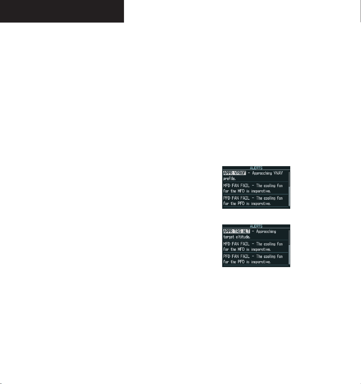
FLIGHT PLANS
3. With the ‘TARGET ALTITUDE’ field highlighted,
turn the
the target altitude and press the
4. Turn the
Wpt’ (AGL) or ‘MSL’, and press the
small and large FMS
small FMS
knob to select ‘Above
knobs to select
ENT
key.
ENT
key.
‘Above Wpt’ uses the altitude of a destination
airport. ‘MSL’ lets you set a specific target alti
tude for any waypoint category: airport, VOR,
NDB, intersection or user waypoint.
5. Turn the
small and large FMS
knobs to select
a distance from the target reference waypoint
and press the
ENT
key. If the target altitude
should occur at the target reference waypoint,
enter a distance of zero.
6. Turn the
small FMS
‘After’, and press the
knob to select ‘Before’ or
ENT
key. This setting
designates whether the offset distance defines
a point before you reach the target reference
waypoint or after you reach the waypoint.
7. When using a flight plan, the target refer
ence waypoint itself can be specified from the
waypoints contained in the flight plan. By
default, the last waypoint in the flight plan
is selected. To select a different waypoint,
turn the
waypoint and press the
small FMS
knob to select the desired
ENT
key.
With the profile set, the vertical speed required (VSR)
is displayed. Expect the following to occur when using the
vertical navigation feature:
At one minute prior to reaching the initial descent
point, the message ‘APPR VPROF - Approaching VNAV
Profile’ is displayed as a PFD alert. The descent (or climb)
-
angle also locks to prevent changes in speed from altering
the profile. If selected, the vertical speed required (VSR)
readout on the default NAV and map pages shows the
desired vertical speed to maintain the proper descent (or
climb) angle. At 500 feet above (or below, for a climb) the
target altitude, an ‘APPR TRG ALT’ - Approaching Target
Altitude” message is provided. The VSR readout on the
Navigation Map Page is blanked out at this point.
-
Figure 8.6.17 Approaching VNAV Profile Message (PFD)
8-64
8. The default profile utilizes a 400 foot-perminute descent rate. To change the rate, turn
the
large FMS
knob to highlight the ‘Target
Vertical Speed’ field and use the small and
large FMS
ENT
knobs to enter a new rate. Press the
key when finished.
Garmin G1000 MFD Pilot’s Guide for the Beechcraft A36/G36 190-00574-00 Rev. A
Figure 8.6.18 Approaching Target Altitude Message (PFD)
VNAV Page Menu Options
The VNAV messages are not enabled until the ‘VNAV
Messages On?’ option is enabled from the VNAV Page
Menu Options. To display the page menu, press the
MENU key (with the VNAV Page displayed). The VNAV
Page Options Menu also allows the pilot to restore VNAV
page defaults.
Page 67
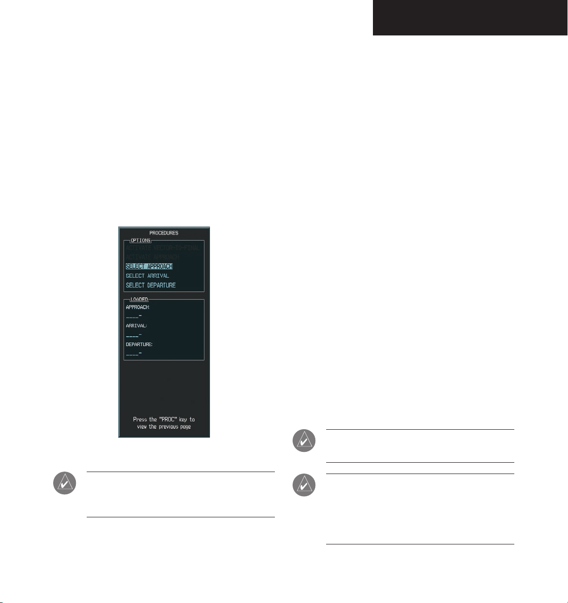
PROCEDURES
8.7 PROCEDURES
ARRIVALS AND DEPARTURES
Based upon the active flight plan or Direct-to
destination, the Procedures Page provides direct access to
approaches, departures and arrivals. In either case, the
departure and destination airports must have associated
published procedures. The Procedures Page is displayed
by pressing the PROC key.
To select a departure:
PROC
1. Press the
Page. Turn the
‘Select Departure’ and press the
key to display the Procedures
large FMS
knob to highlight
ENT
key.
2. The ‘Departure Loading’ page is displayed with
the list of departure options for the departure
airport. Turn the FMS knobs to enter the
ENT
desired departure. Press the
3. ‘Load?’ is highlighted. Press the
key.
ENT
key. The
departure becomes part of the flight plan.
To select an arrival:
PROC
1. Press the
key to display the Procedures
Page. Turn the large FMS knob to highlight
ENT
‘Select Arrival’ and press the
key.
2. The procedures page is displayed. Turn the
small and large FMS
knobs to enter the desired
arrival.
3. The cursor moves to the ‘TRANSITION’ field.
Turn the
large FMS
desired transition waypoint and press the
knob to highlight the
ENT
key. The approach vectors option assumes you
will receive vectors to the final course segment
of the approach and will provide navigation guidance relative to the final approach
course.
Figure 8.7.1 Procedures Page
NOTE: Pilots should be familiar with the section
of the Aeronautical Information Manual (AIM)
regarding the use of GPS.
Garmin G1000 MFD Pilot’s Guide for the Beechcraft A36/G36190-00574-00 Rev. A
NOTE: Vector departures are not part of the
aviation database.
NOTE: The approach vectors option assumes
the pilot will receive vectors to the final course
segment of the approach and will provide navigation guidance on the final approach segment
and extension only.
8-65
Page 68

PROCEDURES
APPROACHES
The G1000 allows you to fly non-precision and
precision approaches to airports with published instrument
approach procedures. All available approaches are part of
the Jeppesen database stored internally in each PFD and
MFD.
The G1000 provides both lateral and vertical guidance
for ILS precision approaches on the PFD, and lateral
guidance for non-precision Localizer, GPS, and VOR and
ADF overlay approaches. GPS position information is
also provided on the mapping portion of the MFD and the
inset map window on the PFD for pilot reference only.
G1000 NAVIGATIONAL GUIDANCE FOR
APPROACHES
The G1000 supports all ARINC 424 leg types that have
associated waypoint fixes. The G1000 uses the following
leg types as part of the Jeppesen database:
• AF - DME arc to a fix
• CF – Course to a fix
• DF – Direct to a fix
• FA – Course from fix to an altitude
• FC – Course from fix to distance
• FD – Course from fix to DME distance
• FM – Course from fix to manual termination
• HA – Hold terminating at altitude
• HF – Hold terminating at a fix
• HM – Hold with manual termination
• IF – Initial fix
• PI – Procedure turn to course intercept
• RF – Constant radius turn to fix
• TF – Track between two fixes
Each of these legs is displayed on the active flight plan.
The G1000 does not support the following legs:
• CA – Course to an altitude
• CD – Course to a DME distance
• CI – Course to an intercept
• CR – Course to a radial
• VA – Heading vector to an altitude
• VD – Heading vector to DME distance
• VI – Heading vector to an intercept
• VM – Heading vector to manual termination
• VR – Heading vector to a radial
NOTE: The G1000 does not provide steering guid-
ance for hold legs and procedure turns (HA, HF,
HM and PI leg types). However, these legs are
drawn on the map and are shown in the flight
plan.
NOTE: The pilot is responsible for determining
database currency for approaches.
.
8-66
Garmin G1000 MFD Pilot’s Guide for the Beechcraft A36/G36 190-00574-00 Rev. A
Page 69

SELECTING APPROACHES
In order to select an approach, there must be an active
flight plan or direct-to which terminates at an airport with
a published approach.
To select an approach:
PROC
1. Press the
Page. Turn the
‘Select Approach’ and press the
approach procedure window appears.
2. Turn the
approach and press the
window appears.
NOTE: The approach vectors option assumes
the pilot will receive vectors to the final course
segment of the approach and will provide navi
gation guidance on the final approach segment
and extension only.
key to display the Procedures
large FMS
knob to highlight
ENT
FMS
knob to select the desired
ENT
key. The transition
key. The
-
PROCEDURES
NOTE: ‘LOAD?’ will add the procedure to the
flight plan without immediately using it for
navigation guidance. This allows you to continue
navigating the original flight plan, but keeps the
procedure available on the Active Flight Plan
Page for quick activation when needed. ‘Acti
vate?’ overrides the enroute portion of the active
flight plan, proceeding directly to the approach
portion.
NOTE: You can also load an approach by pressing
the
APR
softkey.
-
3. Turn the
tion and press the
highlighted. Press the
FMS
knob to select the desired transi-
ENT
key. ‘LOAD?’ is now
ENT
key. Activate the
approach once the approach clearance is
received.
Garmin G1000 MFD Pilot’s Guide for the Beechcraft A36/G36190-00574-00 Rev. A
8-67
Page 70
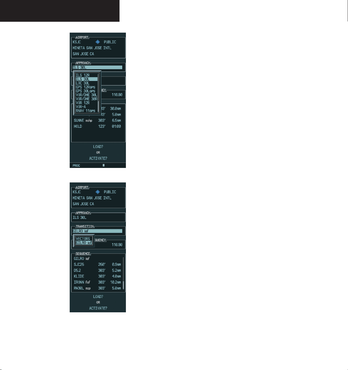
PROCEDURES
Figure 8.7.2 Selecting an Approach Procedure
Not all approaches in the database are approved for
GPS use. As you select an approach, a ‘GPS’ designation
to the right of the procedure name indicates the procedure
can be flown using the GPS receiver. Some procedures
will not have this designation, meaning the GPS receiver
can be used for supplemental navigation guidance only.
If the GPS receiver cannot be used for primary guidance,
you must use the appropriate receiver for the selected
approach (e.g., VOR or ILS). The final course segment of
ILS approaches, for example, must be flown by tuning the
Nav receiver to the proper frequency and selecting that
Nav receiver on the CDI.
A selected approach can be activated or loaded.
Activating the approach also initiates automatic
CDI
scaling transition as the approach progresses. In many
cases, it can be easiest to “Load” the full approach while
still some distance away, enroute to the destination airport.
Later, if vectored to final, use the following steps to select
‘Activate Vector-To-Final’ – which makes the inbound
course to the FAF waypoint active. Otherwise, activate
the full approach using the ‘Activate Approach?’ option.
8-68
Figure 8.7.3 Selecting an Approach Transition
Garmin G1000 MFD Pilot’s Guide for the Beechcraft A36/G36 190-00574-00 Rev. A
Page 71
To activate an approach procedure:
1. With an approach loaded in the active flight
PROC
plan, press the
key to display the Proce-
dures Page.
PROCEDURES
Figure 8.7.4 Activating an Approach Procedure
2. Turn the
large FMS
knob to highlight ‘Activate
Approach’.
ENT
3. Press the
CAUTION: The G1000 is designed to only
complement printed approach plates and vastly
improve situational awareness throughout the
approach. The approach must be flown as it
appears on the approach chart.
key.
NOTE: Specific GPS approach examples are given
in the G1000 Beechcraft Pilot’s Guide Training
Material. They can be used in conjunction with
the G1000 PC training simulator software for
practice in learning what types of approaches
the G1000 supports.
Garmin G1000 MFD Pilot’s Guide for the Beechcraft A36/G36190-00574-00 Rev. A
8-69
Page 72

PROCEDURES
This page intentionally left blank.
8-70
Garmin G1000 MFD Pilot’s Guide for the Beechcraft A36/G36 190-00574-00 Rev. A
Page 73
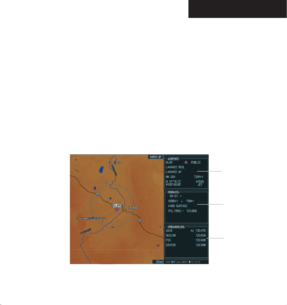
WAYPOINT PAGE GROUP
8.8 WAYPOINT PAGE GROUP
The Waypoint Page Group (WPT) provides information for thousands of airports, VORs, NDBs, intersections,
runways, frequencies and procedures. In addition, a user
waypoint information page displays information for up to
1,000 user-created waypoints. The Waypoint Group consists of the following pages:
• Airport Information Page (INFO)
• Departure Information Page (DP)
• Arrival Information Page (STAR)
• Approach Information Page (APR)
• Intersection Information Page
• NDB Information Page
• VOR Information Page
• User Waypoint Information Page
Page Selection
The Airport Information Page can be selected by
pressing the INFO softkey or by the procedure given
below. The Departure, Arrival, and Approach pages must
be selected from the Airport Information Page using their
corresponding softkeys (DP, STAR, APR). To select any
remaining page:
1. From any page, press and hold the
the Navigation Map Page.
2. Turn the
group. ‘WPT’ appears in the page group icon
located in the lower right corner of the display.
Turn the
‘WPT’ page.
large FMS
small FMS
knob to select the ‘WPT’ page
knob to select the desired
CLR
key to select
Waypoint
Identifier
Airport
Runway
Information
Field
Airport
Frequency
Information
Field
Figure 8.8.1 Airport Information Page
Garmin G1000 MFD Pilot’s Guide for the Beechcraft A36/G36190-00574-00 Rev. A
8-71
Page 74

WAYPOINT PAGE GROUP
AIRPORT INFORMATION PAGE (INFO)
The Airport Information page shows the following
detailed information for the selected airport:
• Airport Information
• Runways
• Frequencies
Airport Information Page Operations
To enter a waypoint identifier:
1. Select the desired ‘WPT’ page and press the
FMS
knob to activate the cursor.
2. Turn the
character of the waypoint’s identifier.
3. Turn the
character field.
4. Turn the
character.
5. Repeat steps 3 and 4 until the identifier is
selected, then press
6. To remove the flashing cursor, press the
knob.
small FMS
large FMS
small FMS
knob to select the first
knob to select the next
knob to select the desired
the ENT key.
FMS
Airports may be selected by identifier, facility name or
city location.
To enter a waypoint facility name or city
location:
1. Select the Airport Information Page.
FMS
2. Press the
3. Turn the
name or location (city) field.
4. Turn the
character.
5. Turn the
character field.
6. Repeat steps 4 and 5 until the facility name or
location is selected, then press
7. To remove the flashing cursor, press the
knob.
Once the identifier, facility name or location is entered,
the airport information page displays information for the
selected airport. As you enter an identifier, facility name
or location, the “SpellNFind”™ feature scrolls through
the database, displaying those waypoints matching the
characters you have entered to that point. If duplicate
entries exist for the entered facility name or location,
additional entries may be viewed by continuing to turn
the small FMS knob during the selection process. If
duplicate entries exist for an entered identifier, a duplicate
waypoint page is displayed once you select the identifier
(by pressing the ENT key).
knob to activate the cursor.
large FMS
small FMS
large FMS
knob to select the facility
knob to select the desired
knob to select the next
the ENT key.
FMS
8-72
Garmin G1000 MFD Pilot’s Guide for the Beechcraft A36/G36 190-00574-00 Rev. A
Page 75

WAYPOINT PAGE GROUP
To select a facility name or city location,
where duplicate entries exist:
Facility Field
Location Field
Figure 8.8.2 Waypoint Facility or City Location
1. Select the desired facility name or location.
2. As you spell the facility name or location, using
the small and
large FMS
knobs, the SpellNFind
feature selects the first entry in the database
based upon the characters you have entered
up to that point.
3. Continue turning the
small FMS
knob to scroll
through any additional database listings for the
selected facility name or location. You can scroll
backwards with the
small FMS
knob if you scroll
past the desired facility name or location.
ENT
4. Press the
key to select the desired facility
name or location.
5. To remove the flashing cursor, press the
FMS
knob.
To select a waypoint identifier from a list
of duplicates:
1. Select the desired airport or navaid identifier.
2. A duplicate waypoints window is displayed.
Turn the
large FMS
knob to select the desired
waypoint and press the ENT key.
3. To remove the flashing cursor, press the
FMS
knob.
Garmin G1000 MFD Pilot’s Guide for the Beechcraft A36/G36190-00574-00 Rev. A
8-73
Page 76

WAYPOINT PAGE GROUP
Airport Runway Information Field
The Airport Runway Information field displays runway
designations, length, surface type and lighting for the
selected airport. A map image of the runway layout and
surrounding area is also displayed on the Airport Runway
Information Page. The map image range is displayed in
the lower left corner and is adjustable using the joystick.
For airports with multiple runways, information for each
runway is available.
To display information for each additional
runway:
FMS
1. Press the
2. Turn the
the Runway designation field.
3. Turn the
runways for the selected airport.
4. Continue turning the
the desired runway.
knob to activate the cursor.
large FMS
small FMS
knob to place the cursor on
knob to display the next
small FMS
knob to select
Rotate the joystick counterclockwise to select a lower
range and rotate it clockwise to select a higher range.
The following descriptions and abbreviations are used
on the Airport Runway Information field:
• Type – Usage type: Public, Military or Private
• Surface – Runway surface types include: Hard,
Turf, Sealed, Gravel, Dirt, Soft, Unknown or Water
• Lighting – Runway lighting types include: No
Lights, Part Time, Full Time, Unknown or Fre
-
quency (for pilot-controlled lighting)
8-74
5. To remove the flashing cursor, press the
knob.
Garmin G1000 MFD Pilot’s Guide for the Beechcraft A36/G36 190-00574-00 Rev. A
FMS
Figure 8.8.3 Runway Information Field
Page 77

WAYPOINT PAGE GROUP
AIRPORT FREQUENCY INFORMATION FIELD
The Airport Frequency Information Field displays radio
frequencies and frequency types for the selected airport, as
well as sector and altitude restrictions (where applicable).
If the selected airport has a localizer-based approach, the
localizer frequency is also listed on the Airport Frequency
Information Field. The Airport Frequency Information
Field may be used to quickly select and tune a COM or
NAV frequency.
To scroll through the frequency list and
tune to a desired frequency on the list:
FMS
1. Press the
2. Turn the
placing the cursor on the desired frequency. If
there are more frequencies in the list than can
be displayed on the screen, a scroll bar along
the right-hand side of the screen indicates
where you are within the list.
3. Press the
quency in the standby field of the ‘COM’ or
‘NAV’ window.
knob to activate the cursor.
FMS
knob to scroll through the list,
ENT
key to place the selected fre-
If a listed frequency has sector or altitude restrictions,
the frequency is preceded by an info designation.
To view usage restrictions for a frequency:
FMS
1. Turn the
knob to place the cursor on the
info designated frequency.
ENT
2. Press the
key to display the restriction
information.
3. To return to the Airport Frequency field, press
the
ENT
key.
Figure 8.8.4 Frequency Information Field
4. To remove the flashing cursor, press the
knob.
Some listed frequencies may include designations for
limited usage, as follows:
• ‘TX’ – transmit only RX - receive only
• ‘PT’ – part time frequency
• ‘i’ – additional information exists, press the
key
Garmin G1000 MFD Pilot’s Guide for the Beechcraft A36/G36190-00574-00 Rev. A
FMS
ENT
8-75
Page 78

WAYPOINT PAGE GROUP
Airport Frequency Descriptions
The Airport Frequency Information field uses the
following descriptions and abbreviations:
• Frequency — Communication frequencies which
may include restrictions:
• Approach
• Arrival
• Class B
• Class C
• CAT
• Departure
• TMA
• Terminal
• TRSA
Communication frequencies without restrictions:
• ATIS
• ASOS
• AWOS
• Center
• Clearance
• Gate
• Control
• Ground
• Helicopter
• Multicom
• Pre-taxi
• Radar
• Ramp
• Other
• Tower
• Unicom
AIRPORT INFORMATION PAGE OPTIONS
The following Airport Information Page
options are available by pressing the MENU key (with the
Airport Information Page displayed):
• Load Approach
• View Departure Airport
• View Destination Airport
• View Recent Airport List
• View Info
• View Departure
• View Arrival
• View Approach
To select an option:
MENU
1. Press the
mation Page.
2. Turn the
option.
3. Press
the ENT
operation.
key while on the Airport Infor-
FMS
knob to select the desired
key to perform the selected option
8-76
Navigation Frequencies:
• ILS
• LOC
Figure 8.8.5 Airport Information Page Menu
Garmin G1000 MFD Pilot’s Guide for the Beechcraft A36/G36 190-00574-00 Rev. A
Page 79

DEPARTURE INFORMATION PAGE (DP)
The Departure Information Page shows the available
Departure Procedures (DPs; also referred to as SIDs)
for the selected airport. Where multiple runways or
transitions are associated with the departure procedure,
that information can also be displayed. A map image
provides a layout diagram for each departure, runway
and transition. To display the Departure Information Page
press the DP softkey.
To scroll through the available departures:
FMS
1. Press the
2. Turn the
the Departure procedure name field.
3. Turn the
available departures for the selected airport.
Continue turning the
the desired departure.
4. Press the
runway field.
5. Turn the
available runways. Continue turning the
FMS
knob to select the desired runway.
knob to activate the cursor.
large FMS
FMS
ENT
small FMS
knob to place the cursor on
knob to display a window of
small FMS
knob to select
key. The cursor moves to the
knob to display a window of
small
WAYPOINT PAGE GROUP
NOTE: ‘ALL’ may appear in the runway field,
indicating the departure procedure applies to all
runways. For airports with parallel runways, ‘B’
may appear at the end of the runway designation
to indicate the departure procedure applies to
both runways.
A departure can be loaded from the Departure Infor-
mation Page.
To load a departure procedure from the
Departure Information Page:
1. Select the desired departure, runway and transi
tion using the steps described previously.
MENU
2. Press
to display the Airport Departure
Page Options.
FMS
3. Turn the
TURE’ and press the
knob to highlight ‘LOAD DEPAR-
ENT
key.
4. The Active Flight Plan Page is displayed. Press
the
FPL
key to return to the Airport Departure
Information Page.
-
ENT
6. Press the
key. The cursor moves to the
Transitions field.
7. Turn the
small FMS
knob to display a window
of available transitions. Continue turning the
FMS
knob to select the desired transition.
ENT
8. Press the
cursor, press the
key. To remove the flashing
FMS
knob.
Garmin G1000 MFD Pilot’s Guide for the Beechcraft A36/G36190-00574-00 Rev. A
Figure 8.8.6 Departure Page Menu
8-77
Page 80
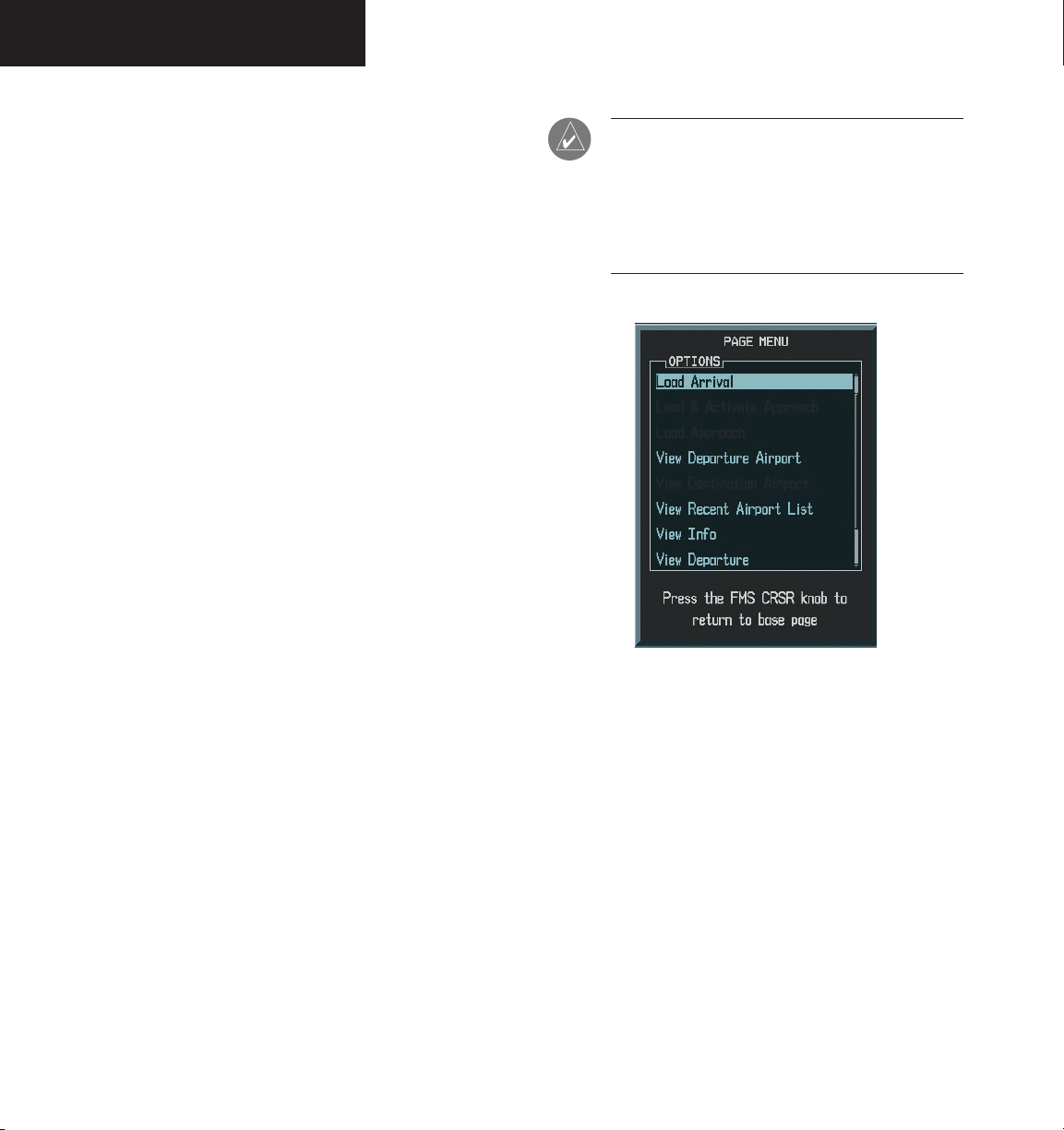
WAYPOINT PAGE GROUP
ARRIVAL INFORMATION PAGE (STAR)
The Arrival Information Page shows the available
Standard Terminal Arrival (STAR) procedures for the
selected airport. Where multiple transitions or runways
are associated with the arrival procedure, that information
may also be displayed. A map image provides a layout
diagram for each arrival, transition and runway. To
display the Airport Arrival Information Page press the
STAR softkey.
To scroll through the available arrivals:
FMS
1. Press the
knob to activate the cursor.
NOTE: ‘ALL’ may appear in the runway field,
indicating the arrival procedure applies to all
runways. For airports with parallel runways, ‘B’
may appear at the end of the runway designation
to indicate the arrival procedure applies to both
runways.
2. Turn the
large FMS
knob to place the cursor on
the ‘ARRIVAL’ procedure name field.
3. Turn the
small FMS
knob to display a window
of available arrivals for the selected airport.
Continue turning the
FMS
knob to select the
desired arrival.
ENT
4. Press the
key. The cursor moves to the
‘TRANSITION’ field.
5. Turn the
small FMS
knob to display a window
of available transitions. Continue turning the
FMS
knob to select the desired transition.
ENT
6. Press the
key. The cursor moves to the
runway field.
7. Turn the
small FMS
knob to display a window of
available runways. Continue turning the FMS
knob to select the desired runway.
ENT
8. Press the
cursor, press the
key. To remove the flashing
FMS
knob.
Figure 8.8.7 Arrival Page Menu
8-78
Garmin G1000 MFD Pilot’s Guide for the Beechcraft A36/G36 190-00574-00 Rev. A
Page 81

WAYPOINT PAGE GROUP
An arrival can be loaded from the Arrival Information
Page.
To load an arrival procedure from the
Arrival Information Page:
1. Select the desired arrival, transition and runway
using the steps described previously.
MENU
2. Press
to display the Arrival Information
Page Options.
3. Turn the
large FMS
ARRIVAL’ and press the
knob to highlight ‘LOAD
ENT
key.
4. The Active Flight Plan Page is displayed. Press
FPL
to return to the Airport Arrival information
Page.
Loading an arrival procedure into the active flight plan
does NOT automatically alter the active flight plan leg or
Direct-to navigation. Once loaded, the arrival is simply
placed at the end of the flight plan. To manually transition
to a loaded arrival, see the procedure below (an alternative
method would be to remove the first occurrence of the
destination airport identifier).
To manually transition to a loaded arrival
procedure:
1. From the Active Flight Plan Page, press the
FMS
knob to activate the cursor and scroll down
through the list of loaded arrival waypoints.
2. When the desired loaded arrival waypoint
is highlighted, press the
ENT
press
to highlight the ‘Activate’ prompt
irect-to
key, then
D
(note that any loaded arrival waypoint may be
selected).
ENT
3. Press
again to confirm activate
Garmin G1000 MFD Pilot’s Guide for the Beechcraft A36/G36190-00574-00 Rev. A
8-79
Page 82

WAYPOINT PAGE GROUP
APPROACH INFORMATION PAGE
The Approach Information page shows the available
approach procedures for a selected airport. Where
multiple initial approach fixes (IAFs) and feeder routes are
available, that information may also be displayed. A map
image provides a layout diagram for each approach and
transition. To display the Airport Approach Information
Page press the APR softkey.
To scroll through the available approaches
and transitions:
FMS
1. Press the
knob to activate the cursor.
NOTE: Not all approaches in the database are
approved for GPS use. As you select an approach,
a GPS designation to the right of the procedure
name indicates the procedure can be flown using
the GPS receiver. Some procedures do not have
this designation, meaning the GPS receiver may
be used for supplemental navigation guidance
only. VOR approaches, for example, must be
flown by tuning the NAV receiver to the proper
frequency and coupling the NAV receiver to the
HSI located on the PFD.
2. Turn the
large FMS
knob to place the cursor on
the ‘APPROACH’ procedure name field.
3. Turn the
small FMS
knob to display a window
of available approaches for the selected airport.
Continue turning the
FMS
knob to select the
desired approach.
ENT
4. Press the
key. The cursor moves to the
transitions (TRANS) field.
5. Turn the
small FMS
knob to display a window
of available transitions. Continue turning the
FMS
knob to select the desired transition or
select ‘VECTORS’ for guidance only along the
final course segment of the approach. Press the
ENT
key. NOTE: the cursor moves through the
remaining fields but they are not selectable.
6. To remove the flashing cursor, press the
knob.
FMS
8-80
Garmin G1000 MFD Pilot’s Guide for the Beechcraft A36/G36 190-00574-00 Rev. A
Page 83
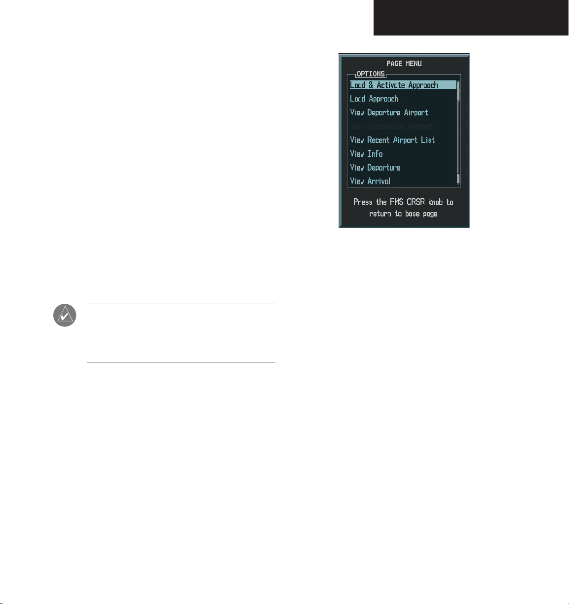
An approach can be loaded from the Airport Informa-
tion Page.
To load an approach from the Airport
Approach Information Page:
1. Select the desired approach and transition.
MENU
2. Press
to display the Approach Informa-
tion Page Options.
WAYPOINT PAGE GROUP
3. Turn the
large FMS
APPROACH’ and press the
knob to highlight ‘LOAD
ENT
key.
4. The Active Flight Plan Page is displayed. Press
FPL
the
key to return to the Airport Information
Approach Page.
5. ‘Load and Activate’ allows you to load the
selected approach into the active flight plan
and activate navigation guidance to the
approach transition.
NOTE: To load and activate an approach from
the Approach Information page, follow the steps
above, but select ‘Load and Activate’ in step
#3.
Figure 8.8.4 Approach Page Menu
Garmin G1000 MFD Pilot’s Guide for the Beechcraft A36/G36190-00574-00 Rev. A
8-81
Page 84

WAYPOINT PAGE GROUP
INTERSECTION INFORMATION PAGE
The Intersection Information Page displays the
following information for a selected intersection:
• Map of surrounding area
• Intersection Identifier and Symbol
• Name
• General location
• Latitude/longitude (degrees/minutes or degrees/
minutes/seconds), MGRS or UTM/UPS
• Nearest VOR/VORTAC/VOR/DME (identifier,
symbol, bearing, distance)
NOTE: The VOR displayed on the Intersection
Information Page is the nearest VOR, not necessarily the VOR used to define the intersection.
Intersection Name and
Symbol
General Location
Intersection
Lat/Lon
8-82
Selected
Intersection
Nearest VOR;
identifier, symbol,
bearing,distance
Figure 8.8.9 Intersection Information Page
Garmin G1000 MFD Pilot’s Guide for the Beechcraft A36/G36 190-00574-00 Rev. A
Page 85

WAYPOINT PAGE GROUP
Intersection Information Page Operations
To change the map range, turn the joystick to the
left to select a lower range, turn it to the right to select
a higher range. NOTE: Intersections can only be selected
by identifier.
To select the Intersection Information Page:
1. From any page, press and momentarily hold
CLR
to select the Navigation Map Page. You
may skip this step if you are already viewing
any of the Map Group pages.
2. Turn the
large FMS
page group. ‘WPT’ is displayed in the page
group icon located in the lower right corner
of the display.
3. Turn the
small FMS
tion Information Page.
knob to select the ‘WPT’
knob to select the Intersec-
To select an Intersection by using an Identifier:
1. With the Intersection Information Page dis
played, press the
FMS
knob to activate the
cursor.
2. Turn the
small and large FMS
a name for the identifier and press the
knobs to enter
ENT
key.
FMS
3. Press the
knob to remove the flashing
cursor.
-
Garmin G1000 MFD Pilot’s Guide for the Beechcraft A36/G36190-00574-00 Rev. A
8-83
Page 86
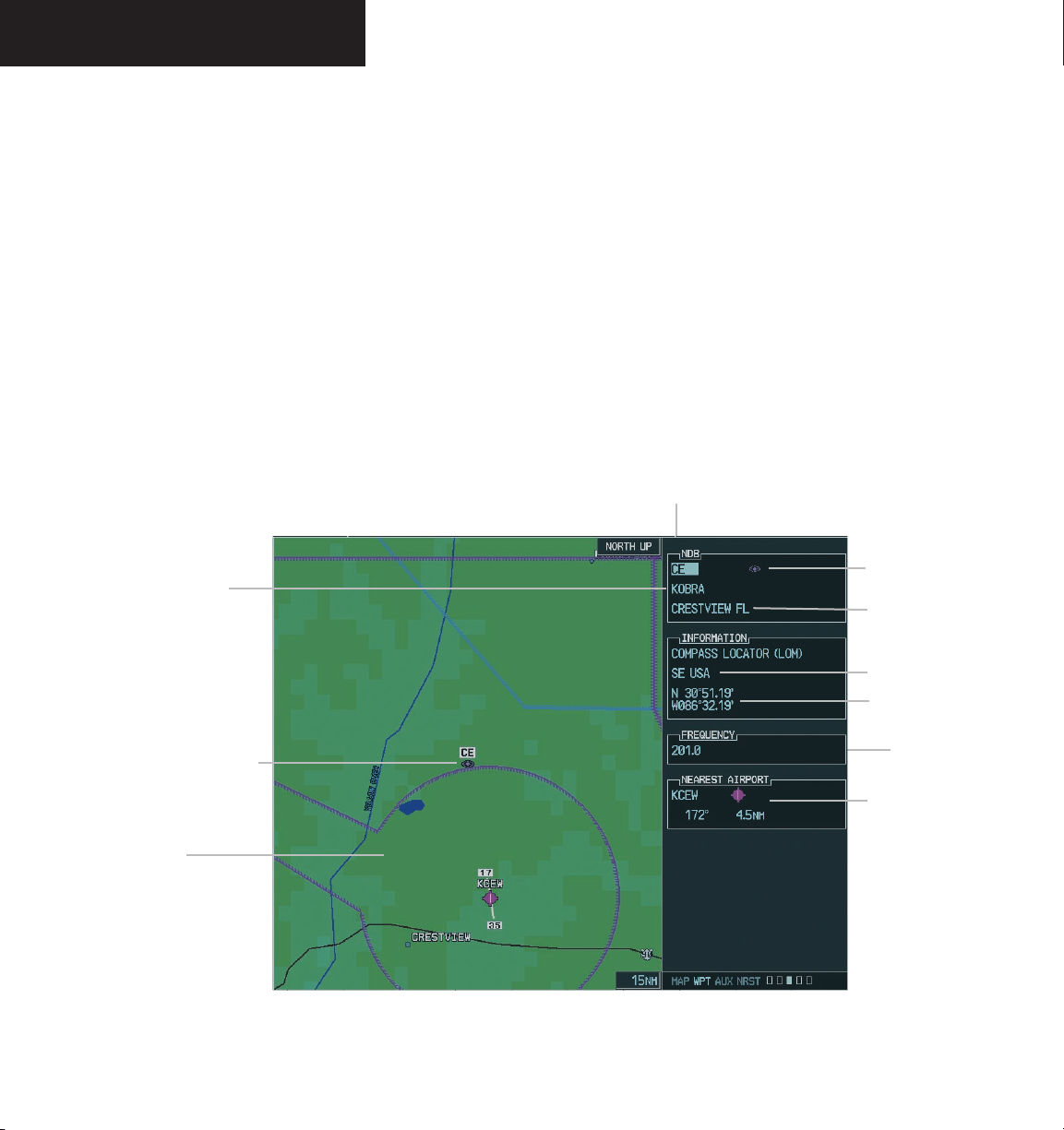
WAYPOINT PAGE GROUP
NDB INFORMATION PAGE
The NDB Information Page displays the following
information for a selected Non-directional beacon:
• Map of surrounding area
• NDB Identifier and Symbol
• Name
• Closest city
• General location
• Latitude/longitude (degrees/minutes or degrees/
minutes/seconds), MGRS or UTM/UPS
• Magnetic Variation in degrees
• Frequency in kilohertz (kHz)
• Nearest airport (identifier, symbol, bearing, distance)
Name
NDB Identifier
NDB Symbol
Closest City
8-84
General Location
Magnetic
Variation
NDB Frequency
NDB Symbol
Nearest Airport;
identifier, symbol,
bearing,distance
Map of
Surrounding Area
Figure 8.8.10 NDB Information Page
Garmin G1000 MFD Pilot’s Guide for the Beechcraft A36/G36 190-00574-00 Rev. A
Page 87

WAYPOINT PAGE GROUP
NDB Information Page Operations
The NDB Information Page allows the following
operations:
• NDB selection by identifier
• NDB selection by name
• NDB selection by closest city
To change the map range, turn the joystick to the left to
select a lower range, turn it to the right to select a higher
range.
To select the NDB Information Page:
CLR
1. From any page, press and hold the
select the Navigation Map Page. You may skip
this step if you are already viewing any of the
Map Group pages.
2. Turn the
large FMS
knob to select the ‘WPT’
page group. ‘WPT’ is displayed in the page
group icon located in the lower right corner
of the display.
3. Turn the
small FMS
knob to select the NDB
Information Page.
key to
To select a NDB by using a Name:
1. With the NDB Information Page displayed,
press the
2. Turn the
FMS
knob to activate the cursor.
large FMS
knobs to highlight the name
field
3. Turn the large and
a name and press the
FMS
4. Press the
knob to remove the flashing
small FMS
ENT
knobs to enter
key.
cursor.
To select a NDB by using the closest city:
1. With the NDB Information Page displayed,
press the
2. Turn the
FMS
knob to activate the cursor.
large FMS
knobs to highlight the clos-
est city field
3. Turn the large and
a city and press the
FMS
4. Press the
knob to remove the flashing
small FMS
ENT
knobs to enter
key.
cursor.
To select a NDB by using an Identifier:
1. With the NDB Information Page displayed,
press the
2. Turn the
a name for the identifier and press the
FMS
knob to activate the cursor.
small and large FMS
knobs to enter
ENT
key.
FMS
3. Press the
knob to remove the flashing
cursor.
Garmin G1000 MFD Pilot’s Guide for the Beechcraft A36/G36190-00574-00 Rev. A
8-85
Page 88
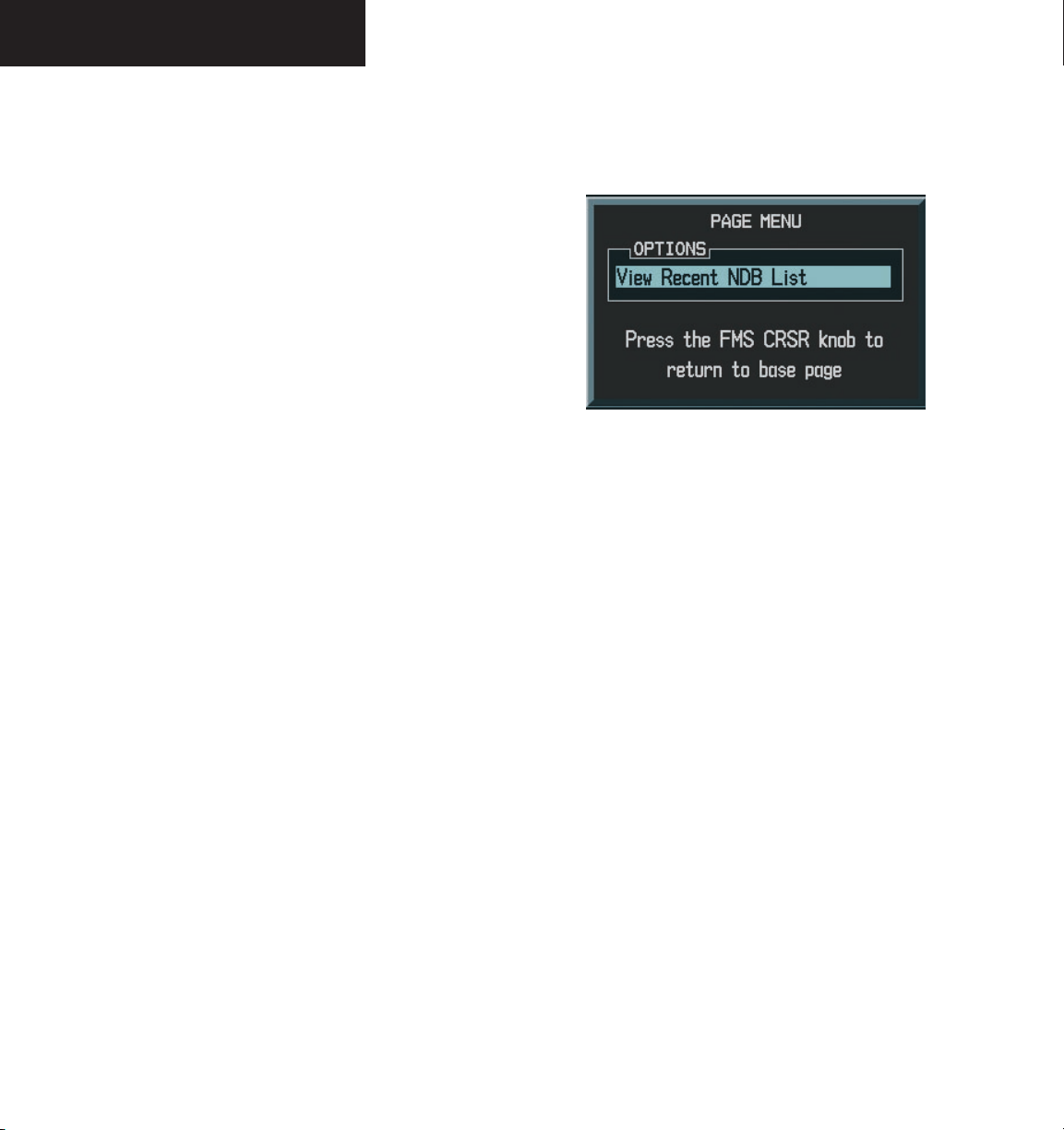
WAYPOINT PAGE GROUP
NDB Information Page Options
The following NDB Information Page Options are
available by pressing the MENU key (with the NDB
Information Page displayed):
• ‘View Recent NDB List’ which allows you to view
the most recent NDB list.
To view the most recent NDB list:
1. Select the NDB Information Page and press
MENU
to display the NDB Information Page
Options. ‘View Recent NDB List’ is highlighted.
ENT
2. Press the
key. Turn the
to select an NDB from the list and press the
ENTER key. The selected NDB is now the active
user NDB.
small FMS
knob
Figure 8.8.11 NDB Page Menu
8-86
Garmin G1000 MFD Pilot’s Guide for the Beechcraft A36/G36 190-00574-00 Rev. A
Page 89
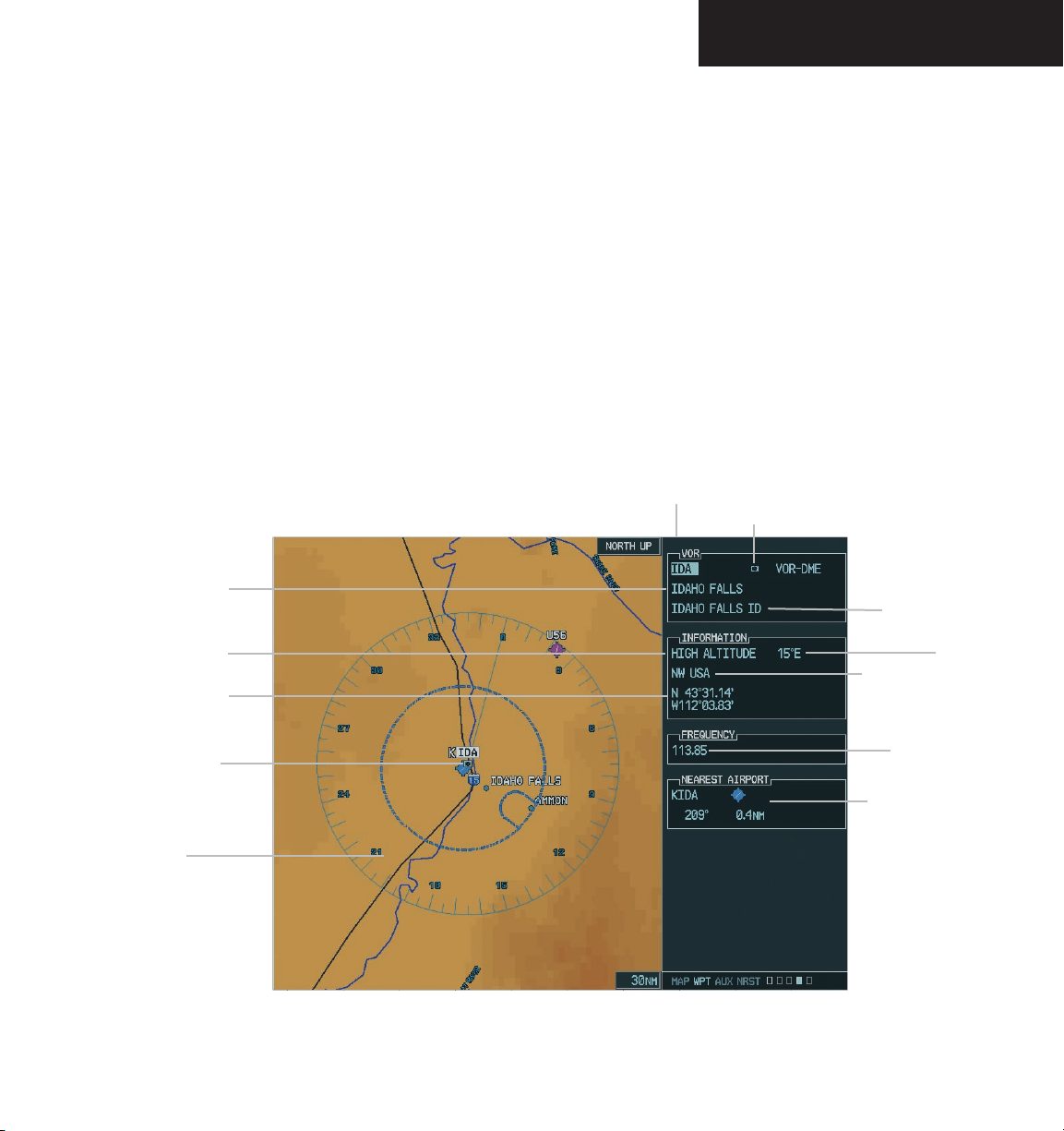
VOR INFORMATION PAGE
The VOR Information Page displays the following in-
formation for a selected VOR:
• Map of surrounding area
• Identifier and Symbol
• Name
• Closest city
• General location
• Latitude/longitude (degrees/minutes or degrees/
minutes/seconds), MGRS or UTM/UPS
• Magnetic Variation in degrees
• Frequency in megahertz (MHz)
• Nearest airport (identifier, symbol, bearing, distance)
WAYPOINT PAGE GROUP
VOR Identifier
VOR Symbol
Name
VOR Type
Latitude/Longitude
VOR Symbol
Map of
Surrounding Area
Closest City
Magnetic
General Location
VOR Frequency
Nearest Airport;
identifier, symbol,
bearing,distance
Figure 8.8.12 VOR Information Page
Garmin G1000 MFD Pilot’s Guide for the Beechcraft A36/G36190-00574-00 Rev. A
Variation
8-87
Page 90

WAYPOINT PAGE GROUP
VOR Information Page Operations
The VOR information page allows the following
operations:
• VOR selection by identifier
• VOR selection by name
• VOR selection by closest city
The map range is adjustable by rotating the joystick.
To change the map range, rotate the joystick counterclockwise to select a lower range and rotate it clockwise to
select a higher range.
To select the VOR Information Page:
CLR
1. From any page, press and hold the
select the Navigation Map Page. You may skip
this step if you are already viewing any of the
Map Group pages.
2. Turn the
large FMS
knob to select the ‘WPT’
page group. ‘WPT’ is displayed in the page
group icon located in the lower right corner
of the display.
key to
To select a VOR by using a Name:
1. With the VOR Information Page displayed, press
the
FMS
knob to activate the cursor.
2. Turn the
large FMS
knobs to highlight the name
field.
3. Turn the
name and press the
4. Press the
large and small FMS
ENT
FMS
knob to remove the flashing
knobs to enter a
key.
cursor.
To select a VOR by using the closest city:
1. With the VOR Information Page displayed, press
the
FMS
knob to activate the cursor.
2. Turn the
large FMS
knobs to highlight the clos-
est city field
3. Turn the large and
a city and press the
FMS
4. Press the
knob to remove the flashing
small FMS
ENT
knobs to enter
key.
cursor.
8-88
3. Turn the
small FMS
knob to select the VOR
Information Page.
To select a VOR by using an Identifier:
1. With the VOR Information Page displayed, press
the
FMS
knob to activate the cursor.
2. Turn the small and
large FMS
knobs to enter
a name for the identifier and press the ENT
key.
FMS
3. Press the
knob to remove the flashing
cursor.
Garmin G1000 MFD Pilot’s Guide for the Beechcraft A36/G36 190-00574-00 Rev. A
Page 91
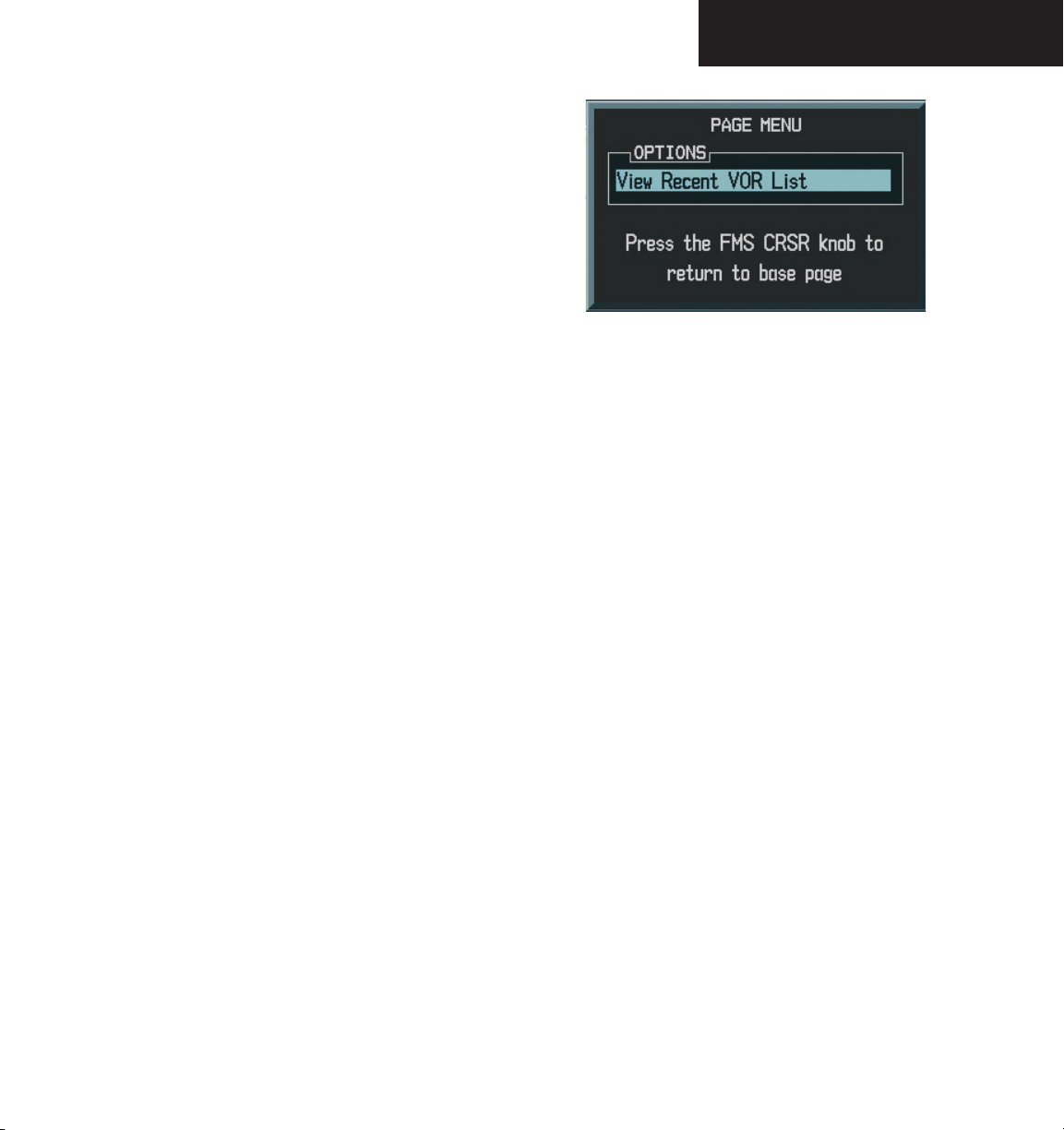
VOR Information Page Options
The following VOR Information Page Options are
available by pressing the MENU key (with the VOR
Information Page displayed):
• ‘View Recent VOR List’ which allows you to view
the most recent VOR list.
To view the most recent VOR list:
WAYPOINT PAGE GROUP
1. Select the VOR Information Page and press
MENU
to display the VOR Information Page
Options. ‘View Recent VOR List is highlighted’.
ENT
2. Press the
key. Turn the
select a VOR from the list and press the
small FMS
knob to
ENT
key. The selected VOR is now the active user
VOR.
Figure 8.8.13 VOR Page Menu
Garmin G1000 MFD Pilot’s Guide for the Beechcraft A36/G36190-00574-00 Rev. A
8-89
Page 92

WAYPOINT PAGE GROUP
USER WAYPOINT INFORMATION PAGE
The G1000 allows the storage of up to 1,000 userdefined waypoints. The User Waypoint Information
Page displays the waypoint name (up to six characters
long), identifier and radial from two reference waypoints,
distance from one reference waypoint, along with the user
waypoints latitude/longitude position.
General Location
User Waypoint Name
User Waypoint Symbol
User Comment
Latitude/Longitude
8-90
User Waypoint Name
and Symbol
Reference Waypoints
User Waypoint List
Waypoint Statistics
Figure 8.8.14 User WPT Information Page
Garmin G1000 MFD Pilot’s Guide for the Beechcraft A36/G36 190-00574-00 Rev. A
Page 93

WAYPOINT PAGE GROUP
The following data is displayed on the User Waypoint
Information Page:
• Map of surrounding area
• Identifier
• Comment
• General location
• Latitude/longitude
• A reference waypoint with identifier, radial, and
distance
• A second reference waypoint with identifier and
radial
• A list of all user waypoints
• Statistics of the number of user waypoint slots
used and available
To select the User Waypoint Information
Page:
CLR
1. From any page, press and hold the
key to
select the Navigation Map Page.
2. Turn the
large FMS
knob to select the ‘WPT’
page group. ‘WPT’ is displayed in the page
group icon located in the lower right corner
of the display.
User Waypoint Information Page Operations
The following operations can be performed from the
User Waypoint Information Page:
• Creating user waypoints (by current location,
entered latitude/longitude position, reference
waypoint specifications, or map pointer location).
• Modifying user waypoint information (by com
ment, latitude/longitude position, or reference
waypoint information)
• Renaming user waypoints
• Deleting user waypoints
-
3. Turn the
small FMS
Waypoint Information Page.
knob to select the User
Garmin G1000 MFD Pilot’s Guide for the Beechcraft A36/G36190-00574-00 Rev. A
8-91
Page 94

WAYPOINT PAGE GROUP
CREATING USER WAYPOINTS
User waypoints may be created from the User Waypoint
Information Page or the Navigation Map Page. To create a
new user waypoint from the User Waypoint Information
Page, enter its name (identifier) and position, or reference
another waypoint by radial and distance.
To create a new user waypoint by entering
its latitude/longitude position:
1. With the User Waypoint Information Page
FMS
displayed, press the
cursor.
2. Turn the
small and large FMS
a name for the new waypoint and press
ENT
key. The message ‘Are you sure you want
to create the new user waypoint’ is displayed.
Press ‘YES’ to create the new waypoint. The
present position is displayed in the information
box. The comment in the comment box is autogenerated based on the reference waypoint
usage. If the waypoint was defined with two
reference waypoints, then this comment would
be generated based on the radials (i.e. OJC354
/ ICT057).
3. Turn the
large FMS
tion field in the information box.
4. Turn the
small and large FMS
position coordinates for the new waypoint.
ENT
5. Press the
key to accept the selected posi-
tion.
FMS
6. Press the
knob to remove the flashing
cursor.
knob to activate the
knobs to enter
knob to highlight the posi-
knobs to enter the
the
NOTE: The number of waypoints that are stored
in memory (USED WPTS) is shown at the bottom
of the User Waypoint Information Page.
To create a new user waypoint by referencing an existing waypoint:
1. With the User Waypoint Information Page
FMS
displayed, press the
knob to activate the
cursor.
2. Turn the
small and large FMS
knobs to enter
a name for the new waypoint and press the
ENT key. The message ‘Are you sure you want
to create the new user waypoint’ is displayed.
Press ‘YES’ to create the new waypoint. The first
reference waypoint (REFERENCE WAYPOINT)
field is highlighted.
3. Turn the
small and large FMS
knobs to enter
the identifier of the reference waypoint. The
reference waypoint can be an airport, VOR,
NDB, intersection or another user waypoint.
Press
ENT
to accept the selected identifier.
4. The cursor moves to the radial (RAD) field. Turn
the
small and large FMS
knobs to enter the
radial from the reference waypoint to the new
user waypoint. Press the
ENT
key to accept the
selected radial.
5. The cursor moves to the distance (DIS) field.
Turn the
small and large FMS
knobs to enter
the distance from the reference waypoint to
ENT
the new user waypoint. Press the
key to
accept the selected distance.
FMS
6. Press the
knob to remove the flashing
cursor.
8-92
Garmin G1000 MFD Pilot’s Guide for the Beechcraft A36/G36 190-00574-00 Rev. A
Page 95

WAYPOINT PAGE GROUP
Creating User Waypoints from the Navigation Map Page
The Navigation Map Page and panning target pointer
provide a quick means of saving your present position as
a user-defined waypoint.
To capture and save your present position
as a user waypoint:
1. With the Navigation Map Page displayed, push
the
joystick
The target pointer is displayed at your present
position.
2. Press the
tion and display the User Waypoint Information Page (only true when the pointer is not
currently highlighting a waypoint).
3. Turn the
waypoint name.
4. Press the
name. The first reference waypoint field is
highlighted.
to activate the panning function.
ENT
key to capture the pointers posi-
small and large FMS
ENT
key to accept the selected
knobs to select a
7. The cursor moves to the distance (DIS) field.
Turn the
small and large FMS
knobs to enter
the distance from the reference waypoint to
ENT
the new user waypoint. Press the
key to
accept the selected distance.
FMS
8. Press the
knob to remove the flashing
cursor.
5. Turn the
small and large FMS
knobs to enter the
identifier of the reference waypoint. The reference waypoint can be an airport, VOR, NDB,
intersection or another user waypoint. Press
the
ENT
key to accept the selected identifier.
6. The cursor moves to the radial (RAD) field. Turn
the
small and large FMS
knobs to enter the
radial from the reference waypoint to the new
user waypoint. Press the
ENT
key to accept the
selected radial.
Garmin G1000 MFD Pilot’s Guide for the Beechcraft A36/G36190-00574-00 Rev. A
8-93
Page 96

WAYPOINT PAGE GROUP
MODIFYING USER WAYPOINTS
To modify an existing waypoint, select that waypoint
on the User Waypoint Information Page and enter the new
position information directly over the old information.
To modify a user waypoint by changing its
latitude/longitude position:
1. With the User Waypoint Information Page
FMS
displayed, press the
cursor.
2. Turn the
a name for the new waypoint and press the
ENT
to create the new user waypoint’ is displayed.
Press ‘YES’ to create the new waypoint. The first
reference waypoint (REFERENCE WAYPOINT)
field is highlighted.
3. Turn the
tion field in the Information Box.
4. Turn the
the new position coordinates and press the
ENT
5. Press the
cursor.
small and large FMS
key. The message ‘Are you sure you want
large FMS
small and large FMS
key to accept the selected position.
FMS
knob to remove the flashing
knob to activate the
knobs to enter
knob to highlight the posi-
knobs to enter
To modify a user waypoint by changing
reference waypoint information:
1. With the User Waypoint Information Page
FMS
displayed, press the
cursor.
2. Turn the
a name for the new waypoint and press the
ENT
to create the new user waypoint’ is displayed.
Press ‘YES’ to create the new waypoint. The first
reference waypoint (REFERENCE WAYPOINT)
field is highlighted if you want to change the
reference waypoint. Otherwise, continue turning the
(RAD) or distance (DIS) field, as desired.
3. Turn the
the identifier — if desired — of the reference
waypoint. The reference waypoint can be an
airport, VOR, NDB, intersection or another
user waypoint. Press the
selected identifier.
4. The cursor moves to the radial (RAD) field. Use
the small and
radial from the reference waypoint, if desired.
Press
small and large FMS
key. The message ‘Are you sure you want
large FMS
small and large FMS
ENT
to accept the selected radial.
knob to highlight the radial
large FMS
knob to activate the
knobs to enter
knobs to change
ENT
key to accept the
knobs to change the
8-94
5. The cursor moves to the distance (DIS) field.
Turn the
the distance from the reference waypoint to
the new user waypoint, if desired. Press the
ENT
6. Press the
cursor.
Garmin G1000 MFD Pilot’s Guide for the Beechcraft A36/G36 190-00574-00 Rev. A
small and large FMS
key to accept the selected distance.
FMS
knob to remove the flashing
knobs to change
Page 97
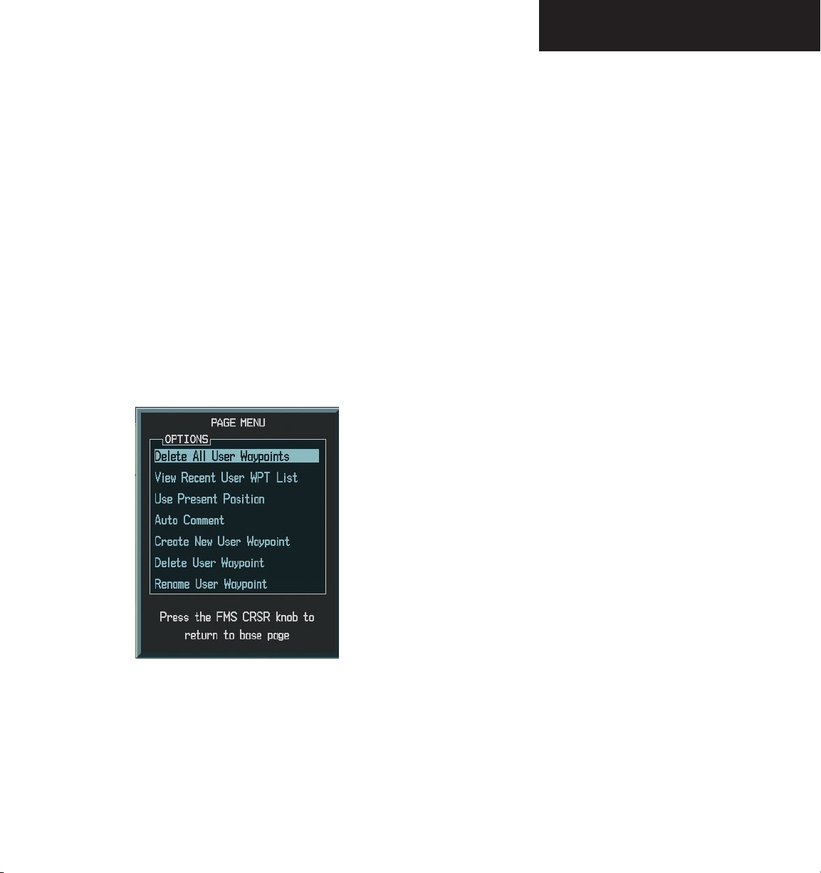
WAYPOINT PAGE GROUP
USER WAYPOINT INFORMATION PAGE OPTIONS
The following User Waypoint Information Page
Options are available by pressing the MENU key (with the
User Waypoint Information Page displayed):
• Delete All User Waypoints
• View Recent User WPT List
• Use Present Position
• Auto Comment
• Create New user Waypoint
• Delete User Waypoint
• Rename User Waypoint
‘Delete All User Waypoints’ allows you to delete all
user waypoints from memory.
To delete all user waypoints:
1. Select the User Waypoint Information Page
MENU
and press
Information Page Options.
2. Turn the
User Waypoints’ and press the
firmation windows is displayed. Press the
key to accept ‘YES’ or turn the
to highlight ‘NO’ and press the
‘View Recent User WPT List’ allows you to view the
most recent user waypoint list.
To view the most recent user waypoint list:
1. Select the User Waypoint Information Page
and press
Information Page Options.
2. Turn the
User WPT List’ and press the
the
the list and press the
waypoint is now the active user waypoint.
large FMS
large FMS
small FMS
to display the User Waypoint
knob to select ‘Delete All
ENT
key. A con-
large FMS
ENT
key.
MENU
to display the User Waypoint
knob to select ‘View Recent
ENT
key. Turn
knob to select a waypoint from
ENT
key. The selected
ENT
knob
Figure 8.8.15 User WPT Page Menu
Garmin G1000 MFD Pilot’s Guide for the Beechcraft A36/G36190-00574-00 Rev. A
8-95
Page 98

WAYPOINT PAGE GROUP
Use ‘Present Position’ when selected will move the
currently selected user waypoint to the present position
of the aircraft.
NOTE: The user waypoint is set to the airplane’s
position at the time when this option was
selected.
To move the currently selected user
waypoint to the present position of the
aircraft:
1. Select the User Waypoint Information Page
MENU
and press the
key to display the User
Waypoint Information Page options.
2. Turn the
large FMS
Position’ and press the
3. Highlight the position and press
knob to select ‘Use Present
ENT
key.
the
ENT
key.
‘Auto Comment’ when selected will overwrite the
currently selected user waypoints comment with an
automatically generated comment. The auto comment is
in the same format as comments that are generated for user
waypoints that have not specified a unique user waypoint
comment. The auto comment can be one of three styles:
To overwrite the currently selected user
waypoints comment with an automatically
generated comment:
1. Select the desired waypoint on the User
Waypoint Information Page and press
MENU
to display the User Waypoint Information Page
options.
2. Turn the
ment’ and press the
large FMS
knob to select ‘Auto Com-
ENT
key.
8-96
• REF1BRG1 / DIS1 - if the user waypoint position
is defined by a reference 1 waypoint radial and
distance (this is generally the default case, but
the default case could also be the BLANK (c) case
if there are no reference waypoints near the user
waypoints position)
• REF1BRG1 / REF2BRG2 - if the user waypoint
position is defined by a reference 1 waypoint
radial and a reference 2 waypoint radial
• BLANK - if no reference waypoints are near the
user waypoints position
Garmin G1000 MFD Pilot’s Guide for the Beechcraft A36/G36 190-00574-00 Rev. A
Page 99

WAYPOINT PAGE GROUP
Create New Waypoint allows the pilot to create a new
user waypoint.
To create a new waypoint:
1. From the User Waypoint Information Page,
MENU
press the
key to display the User
Waypoint Information Page Options or press
the
NEW
softkey.
2. Turn the
large FMS
New Waypoint and press the
3. Turn the
small and large FMS
knob to highlight Create
ENT
key.
knobs to enter
a name for the new waypoint and press the
ENT
key. The message ‘Are you sure you want
to create the new user waypoint’ is displayed.
Press ‘YES’ to create the new waypoint. The
present position is displayed in the information box. The first reference waypoint field is
highlighted
4. Turn the
small and large FMS
knobs to enter the
identifier of the reference waypoint. The reference waypoint can be an airport, VOR, NDB,
intersection or another user waypoint. Press
the
ENT
key to accept the selected identifier.
5. The cursor moves to the radial (RAD) field. Turn
the
small and large FMS
knobs to enter the
radial from the reference waypoint to the new
user waypoint. Press the
ENT
key to accept the
selected radial.
Delete User Waypoint allows the pilot to delete a user
waypoint.
To delete a user waypoint:
1. Select the User Waypoint Information Page
MENU
and press
Information Page Options or press the
to display the User Waypoint
DELETE
softkey.
2. Turn the
large FMS
Waypoint’ and press the
knob to select ‘Delete User
ENT
key. The message
‘Would you like to delete the user waypoint’ is
displayed. Press ‘YES’ to delete the waypoint.
Rename User Waypoint allows the pilot to rename a
user waypoint.
To rename a user waypoint:
1. Select the User Waypoint Information Page
MENU
and press
Information Page Options or press the
to display the User Waypoint
RENAME
softkey.
2. Turn the
large FMS
User Waypoint’ and press the
waypoint field is highlighted. Turn the
large FMS
Press the
knobs to rename the user waypoint.
ENT
knob to select ‘Rename
ENT
key.
key. The user
small and
3. The message ‘Would you like to rename the
user waypoint’ is displayed. Press ‘YES’ to
rename the new user waypoint.
6. Press the
cursor.
FMS
knob to remove the flashing
Garmin G1000 MFD Pilot’s Guide for the Beechcraft A36/G36190-00574-00 Rev. A
8-97
Page 100

WAYPOINT PAGE GROUP
This page intentionally left blank.
8-98
Garmin G1000 MFD Pilot’s Guide for the Beechcraft A36/G36 190-00574-00 Rev. A
 Loading...