

Page 1

TM
G1000
system overview for
the Mooney M20M & M20R
Page 2

Record of Revisions
Revision Date of Revision Revision Page Range Description
A 10/18/04 2-1 – 2-11 Production Release.
190-00442-00 Rev. AGarmin G1000 System Overview for Mooney M20M & M20R
Page 3
SYSTEM OVERVIEW
2.1 SYSTEM DESCRIPTION
Garmin® International Inc., a unit of Garmin Ltd.
introduces the G1000 Integrated Cockpit System for
Mooney M20M and M20R aircraft. The G1000 includes
the following Line Replaceable Units (LRUs):
• GDU 1040 Primary Flight Display (PFD)
• GDU 1040 Multi Function Display (MFD)
• GIA 63 Integrated Avionics Units (2)
• GEA 71 Engine/Airframe Unit
• GDC 74A
• GRS 77 Attitude & Heading Reference System
(AHRS)
• GMU 44 Magnetometer
• GMA 1347 Audio System with integrated Marker
Beacon Receiver
• GTX 32 Modes A/C or GTX 33 Mode S
Transponder
LRUs are further described in Section 2.2. All LRUs
have a modular design, which greatly eases troubleshooting and maintenance of the G1000 system. A top-level
G1000 block diagram is given in Figure 2.2.1 to support
the description of the system.
Air Data Computer (ADC)
and the right display is configured as a Multi Func
tion Display. Both GDU 1040s link and display all
functions of the G1000 system during flight. The
displays communicate with each other through a
High-Speed Data Bus (HSDB) Ethernet connection.
Each display is paired with a GIA 63 Integrated
Avionics Unit, also via Ethernet connection.
• GMA 1347 – The GMA 1347 integrates NAV/COM
digital audio, intercom system and marker beacon
controls. The GMA 1347 also controls manual
display reversionary mode (large red button). The
GMA 1347 is installed between the MFD and PFD.
The GMA 1347 communicates with both GIA 63s
using RS-232 digital interface.
-
2.2 LRU DESCRIPTIONS
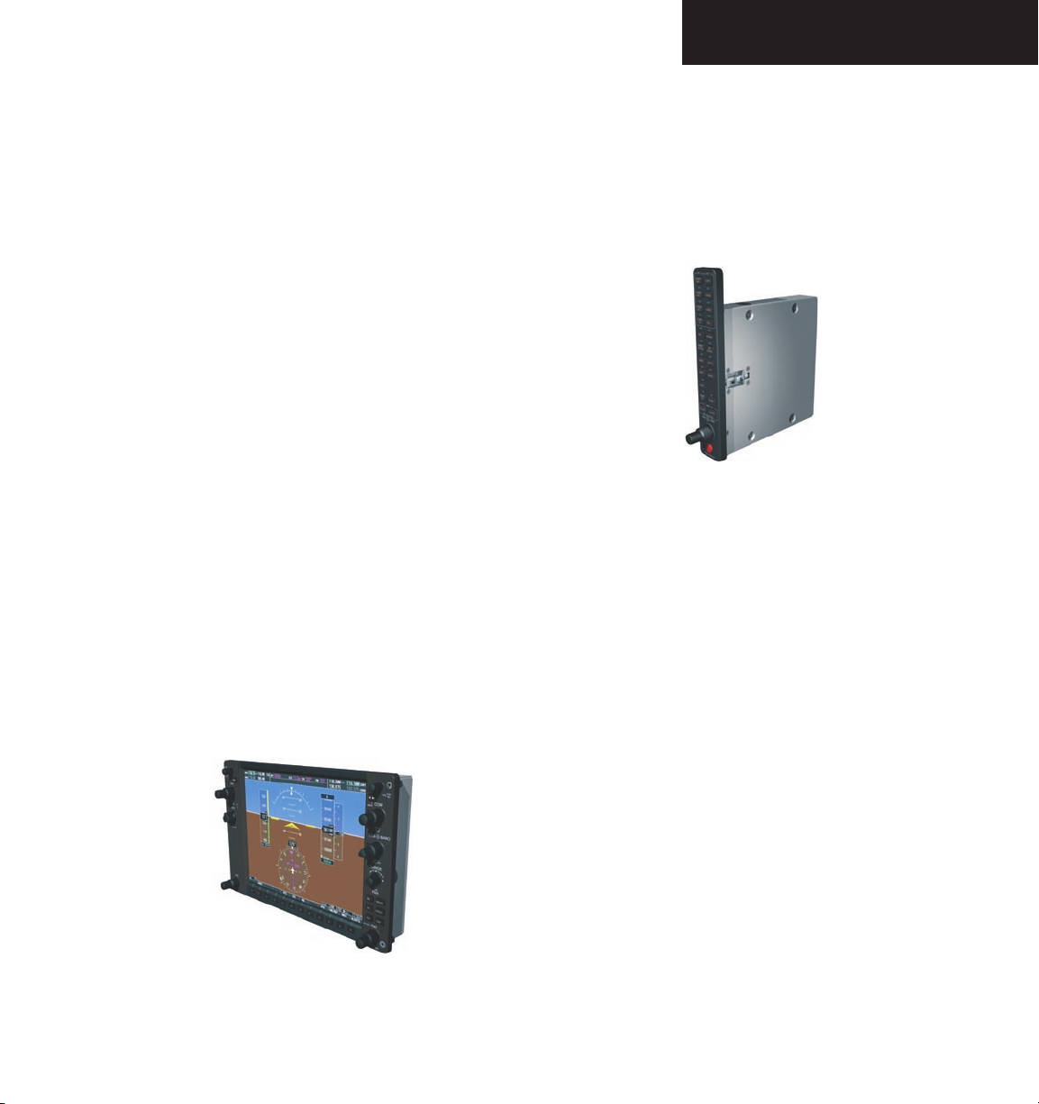
• GDU 1040 – The GDU 1040 has a 10.4-inch
LCD display with 1024 x 768 resolution. The left
display is configured as a Primary Flight Display
190-00442-00 Rev. A Garmin G1000 System Overview for Mooney M20M & M20R
2-1
Page 4
SYSTEM OVERVIEW
• GIA 63 – The GIA 63 is the central ‘Integrated
Avionics Unit’ of the G1000 system. The GIA 63
functions as a main communications hub, linking all
LRUs with the PFD and MFD displays. Each GIA 63
contains a GPS receiver, VHF COM/NAV/GS receivers, and system integration microprocessors. Each
GIA 63 is paired with a respective GDU 1040 display
through Ethernet. GIAs are not paired together and
do not communicate with each other directly.
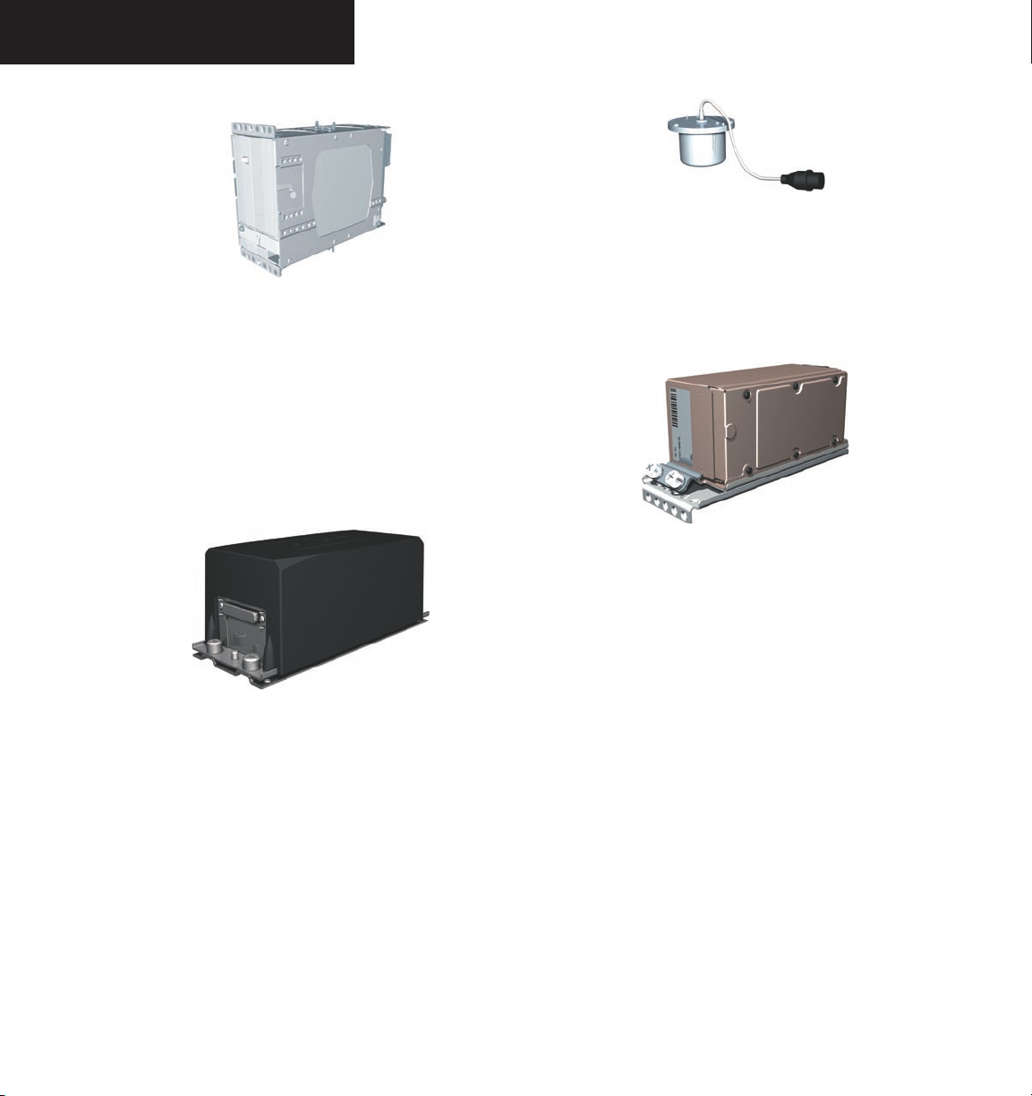
• GRS 77 – The GRS 77 is an Attitude and Heading
Reference System (AHRS) that provides aircraft attitude and heading information to the G1000 displays
and the GIA 63s. The unit contains advanced sensors, accelerometers, and rate sensors. In addition,
the GRS 77 interfaces with both the GDC 74A Air
Data Computer and the GMU 44 Magnetometer.
The GRS 77 also utilizes GPS signals sent from
the GIA 63. Attitude and heading information are
sent using an ARINC 429 digital interface to both
GDU 1040s and GIA 63s.
• GMU 44 – The GMU 44 Magnetometer measures
local magnetic field information. Data is sent to
the GRS 77 ARHS for processing to determine aircraft magnetic heading. This unit receives power
directly from the GRS 77 and communicates with
the GRS 77 using RS-485 digital interface.
• GDC 74A – The GDC 74A Air Data Computer
processes information from the pitot/static system
and the outside air temperature (OAT) sensor. The
GDC 74A provides pressure altitude, airspeed,
vertical speed, and OAT information to the G1000
system. The GDC 74A communicates with both
GIA 63s, GDU 1040s, and GRS 77 using ARINC 429
digital interface.
2-2
190-00442-00 Rev. AGarmin G1000 System Overview for Mooney M20M & M20R
Page 5
SYSTEM OVERVIEW
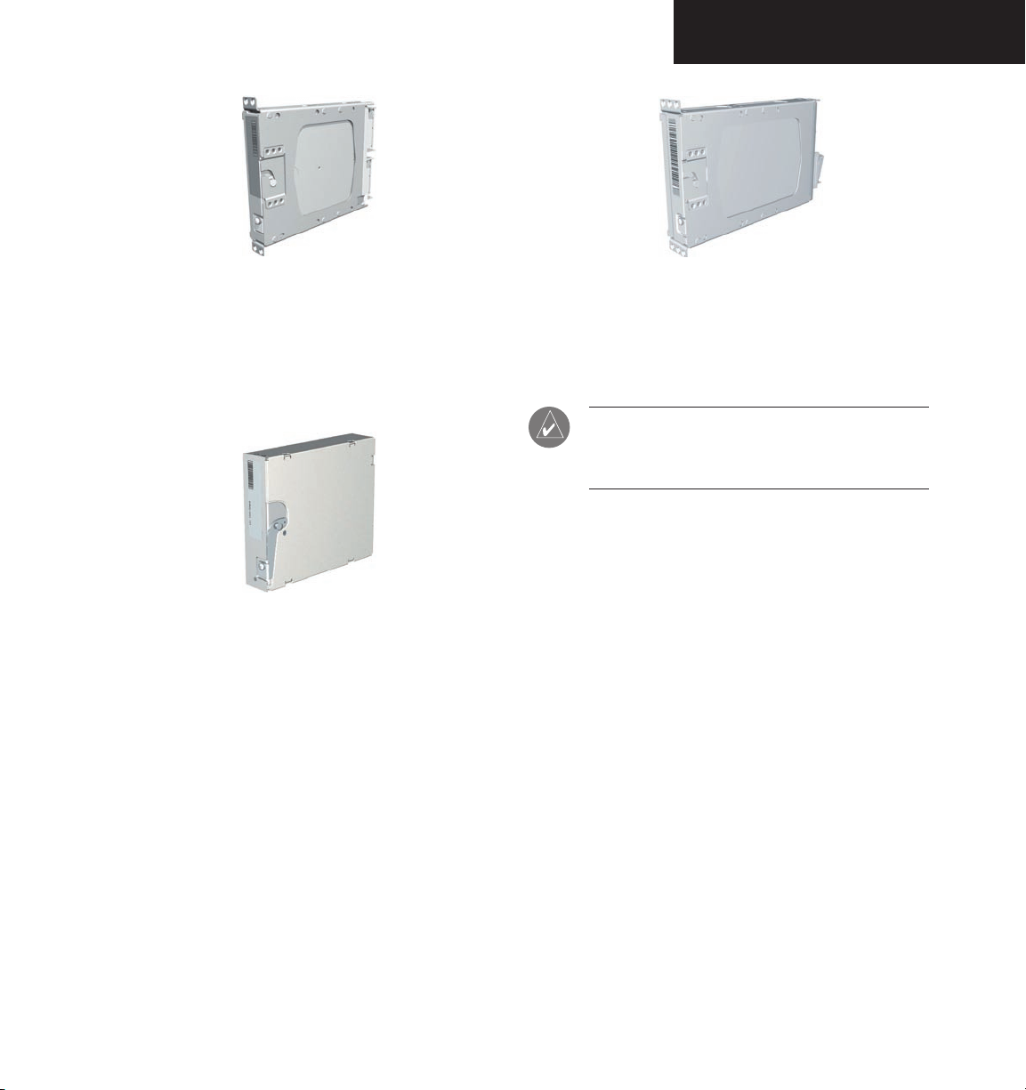
• GEA 71 – The GEA 71 receives and processes signals
from engine and airframe sensors. Sensor types
include engine temperature and pressure sensors
as well as fuel measurement and pressure sensors.
The GEA 71 communicates with both GIA 63s using
RS-485 digital interface.
• GTX 32 – The GTX 32 is a solid-state transponder
providing Modes A and C operation. The PFD
provides control and operation of the GTX 32.
The transponder communicates with both GIA 63s
through RS-232 digital interface.
• GTX 33 – The GTX 33 is a solid-state Mode S
transponder providing Modes A, C, and S operation. The PFD provides control and operation of
the GTX 33. The transponder communicates with
both GIA 63s through RS-232 digital interface.
NOTE: See the Aircraft Flight Manual to deter-
mine which transponder is installed in your
aircraft.
190-00442-00 Rev. A Garmin G1000 System Overview for Mooney M20M & M20R
2-3
Page 6

SYSTEM OVERVIEW
No. 1 GIA
63
Integrated Avionics Uni
t
System Inegration Processor
s
I/O Processor
s
VHF
COM
VHF NAV/L
OC
G
P
S
Glideslo
pe
No. 2 GIA
63
Integrated Avionics Uni
t
System Integration Processor
s
I/O Processor
s
VHF
COM
VHF NAV/L
OC
G
P
S
Glideslo
pe
G
TX
32
or GTX
33
Transponde
r
High-Speed Data Bus (Ethernet)
Reversionary
Control
G
EA 7
1
Engine/Airfram
e
U
ni
t
G
DC 74
A
Air Dat
a
Compute
r
O
A
T
Airspee
d
Altit
ude
Vertical Spee
d
G
RS 7
7
AHR
S
Attit
ude
Rate of Tur
n
Slip/Ski
d
G
MU 4
4
Magnetomete
r
Headin
g
GPS Outpu
t
GPS Outpu
t
Reversionary
Control
Figure 2.2.1 G1000 System Block Diagram
2-4
190-00442-00 Rev. AGarmin G1000 System Overview for Mooney M20M & M20R
Page 7

2.3 PFD/MFD CONTROLS
SYSTEM OVERVIEW
1 2 4 6
3
5
7
8
9
17
Figure 2.3.1 PFD/MFD Controls
1
NAV VOL / ID Control
2
NAV Frequency Toggle Key
3
NAV Frequency Selector
4
Heading Selector
5
Joystick
6
Course/Baro Selector
7
COM Frequency Selector
8
COM Frequency Toggle Key
9
COM VOL/SQ Control
10
Direct-to Key
11
Flight Plan Key
12
Clear Key
13
Flight Management Knobs
14
Menu Key
15
Procedures Key
16
Enter Key
17
Altitude Reference Control
10
11
12
13
190-00442-00 Rev. A Garmin G1000 System Overview for Mooney M20M & M20R
14
15
16
2-5
Page 8

SYSTEM OVERVIEW
The G1000 controls and keys have been designed to
simplify operations and minimize workload and time to
access sophisticated functionality. The following provides
an overview of the primary function(s) for each key and
control.
• (1) NAV VOL / ID Control – Controls the NAV
audio level. Press to toggle the ident filter ON and
OFF. Volume increase and decrease is shown in the
field as a percentage.
• (2) NAV Frequency Toggle Key – Swaps the
standby NAV frequency and the active NAV frequency when pressed (the standby NAV frequency
is white whereas the active NAV frequency is green).
Note that NAV frequencies are shown as active only
when the HSI is set to either NAV1 or NAV2.
• (3) NAV Frequency Selector – The concentric
knobs tune the MHz (large) and kHz (small) standby
frequencies for the NAV receiver. Press on the small
knob to toggle the tuning cursor (cyan box) between
the NAV1 and NAV2 fields.
• (4) Heading Selector – Manually selects a heading.
When this knob is pressed, a window displaying a
digital heading momentarily appears to the left of the
Heading Indicator and the heading bug synchronizes
with the compass lubber line.
• (5) Joystick – Changes the map scale when rotated.
When pressed, it activates the map pointer.
• (6) CRS/BARO Selector – The large knob sets the
altimeter barometric pressure and the small knob
adjusts course. Course is adjustable when the HSI is
in NAV 1 & 2 or OBS/SUSP modes only). Pressing
the small knob centers the CDI on the currently
selected VOR.
• (7) COM Frequency Selector – The concentric
knobs tune the MHz (large) and kHz (small) standby
frequencies for the COM receiver. Pressing the
small knob toggles the tuning cursor (cyan box)
between the COM 1 and COM 2 fields.
• (8) COM Frequency Toggle Key – Swaps the
standby COM frequency and the active COM frequency. Pressing and holding this key for ten seconds automatically makes the 121.5 MHz emergency
frequency the active frequency.
• (9) COM VOL/SQ Control – Controls the COM
audio level. Pressing this knob turns the COM automatic squelch ON and OFF. Audio volume increase
and decrease is shown in the field as a percentage.
• (10) DIRECT-TO Key ( ) – Allows the user to
enter a destination waypoint and establish a direct
course to the selected destination (specified by
identifier, chosen from the active route, or taken
from the map cursor position).
• (11) FPL Key – Displays the active Flight Plan
Page for creating and editing the active flight plan
or accessing stored flight plans.
• (12) CLR Key (Default) – Erases information or
cancels an entry. To immediately display the Navigation Map Page, press and hold CLR (MFD only).
• (13) FMS Knobs – The concentric knobs are
used to select the page to be viewed (only on the
MFD)— the large FMS knob selects a page group
(MAP, WPT, AUX, NRST) while the small FMS
knob selects a specific page within the page group.
Pressing the small FMS knob turns the on-screen
cursor ON and OFF. When the cursor is on, data
may be entered in the different windows using a
combination of the small and large FMS knobs.
The large FMS knob is used to move the cursor on
the page. The small FMS knob is used to select
individual characters for the highlighted cursor location. When the G1000 displays a list of information
that is too long for the display screen, a scroll bar
appears along the right side of the display. The scroll
bar graphically indicates the number of additional
items available within the selected category.
2-6
190-00442-00 Rev. AGarmin G1000 System Overview for Mooney M20M & M20R
Page 9

SYSTEM OVERVIEW
Press the FMS/CSRS to activate the cursor and turn
the large FMS knob to scroll through the list.
• (14) MENU Key – Displays a context-sensitive
list of options. This options list allows the user to
access additional features or make settings changes
that relate to certain pages.
• (15) PROC Key – Selects approaches, departures
and arrivals from the flight plan. When using a
flight plan, available procedures for departure and/
or arrival airport are automatically suggested. If a
flight plan is not used, the desired airport, and the
desired procedure may be selected. The procedures
key selects IFR departure procedures (DPs), arrival
procedures (STARs) and approaches (IAPs) from
the database and loads them into the active flight
plan.
• (16) ENT Key – Accepts a menu selection or data
entry. The enter key is used to approve an operation
or complete data entry. It is also used to confirm
selections and information entries.
• (17) Altitude Reference Control – Sets the refer-
ence altitude in the window over the altimeter tape.
The large ALT knob selects thousands, the small
ALT knob selects hundreds.
2.4 SECURE DIGITAL CARDS
The GDU 1040 data card slots use Secure Digital (SD)
cards. SD cards are used for aviation database updates
and terrain database storage.
To install an SD card:
1. Press the card into place until it seats on the
internal connector and the front of the card is
flush with the face of the display bezel
To remove an SD card:
1. Gently press on the card to release the spring
latch and partially eject the card.
NOTE: See Appendix A of this Pilot’s Guide for
instructions on updating the aviation database.
NOTE: The selected (green) COM is controlled
by the mic select on the audio control panel
(GMA 1347).
190-00442-00 Rev. A Garmin G1000 System Overview for Mooney M20M & M20R
2-7
Page 10

SYSTEM OVERVIEW
2.5 SYSTEM POWER-UP
The G1000 system is integrated with the aircraft electrical system and receives power directly from electrical
busses. Garmin G1000 PFD/MFD and supporting subsystems include both power-on and continuous built-in
test features that exercise the processor, RAM, ROM, external inputs and outputs to provide safe operation.
While the system begins to initialize, test annunciations are displayed to the pilot at power up, as shown
in Figure 2.5.1. All system annunciations should clear
within 1 minute of power up. The GMA 1347 also annunciates all bezel lights briefly upon power up.
On the PFD, the AHRS system displays the ‘AHRS
ALIGN: Keep Wings Level’ message and begins to initialize. AHRS should display valid attitude and heading fields
within 1 minute of power up. The AHRS can align itself
while the aircraft taxis or during level flight.
NOTE: See the approved Airplane Flight Manual
Supplement for specific procedures concerning
avionics power application and emergency
power supply operation.
NOTE: See the Annunciations & Alerts Pilot’s
Guide for more information regarding system
annunciations and alerts.
2-8
Figure 2.5.1 PFD Initialization
190-00442-00 Rev. AGarmin G1000 System Overview for Mooney M20M & M20R
Page 11

SYSTEM OVERVIEW
When the MFD powers up, the MFD Power-Up page
displays the following data:
• System version information
• Copyright string
• Garmin Corporation name
• Checklist filename
• Land database name and version
• Obstacle database name and version
• Terrain database name and version
• Aviation database name, version, and effective
dates
When the list has been reviewed for currency (to ensure
that no databases have expired), the pilot is prompted to
continue. Current database information is displayed with
valid operating dates, cycle number and database type in
-
dicated.
Press the
ENT key to acknowledge the list information and proceed to the Navigation Map Page. When the
system has acquired a sufficient number of satellites to
determine a position, the Navigation Map Page appears
showing your present position.
Figure 2.5.2 MFD Power-up Page
190-00442-00 Rev. A Garmin G1000 System Overview for Mooney M20M & M20R
2-9
Page 12

SYSTEM OVERVIEW
2.6 DISPLAY BACKLIGHTING
The G1000 PFD and MFD displays use photocell technology to automatically adjust for ambient lighting con
ditions. Photocell calibration curves are pre-configured
to optimize display appearance through a broad range of
cockpit lighting conditions. PFD, MFD, and GMA 1347
bezel/key lighting is normally controlled directly by the
existing instrument panel dimmer bus.
If desired, the PFD and MFD display backlights may
be adjusted manually. PFD, MFD, and GMA 1347 bezel/key brightness can also be adjusted manually as well.
GMA 1347 bezel/key brightness is directly tied to the
MFD bezel/key adjustment.
Refer to the G1000 Primary Flight Display Pilot’s
Guide for instructions on how to manually adjust
the backlighting.
-
2.7 G1000 REVERSIONARY MODE
G1000 PFD and MFD are connected together on a single Ethernet bus, allowing communication between the
two units to occur at a high rate of speed. Each GIA 63
Integrated Avionics Units is connected to a single display,
as shown in Figure 2.2.1. This allows the units to share
information, enabling true integration of the system.
In normal operating mode, the PFD displays graphical
flight instrumentation in lieu of traditional gyro instruments. Attitude, heading, airspeed, altitude, and vertical
speed are all shown on one display. The MFD shows a
full-color moving map with navigation information. Both
displays offer control over COM and NAV frequency selectors, as well as heading, course/baro and altitude reference
functions. On the left of the MFD display, an Engine Indication System (EIS) cluster shows graphical depictions of
engine and airframe instrumentation. Figure 2.7.1 gives
an example of the G1000 system in normal mode.
Should a failure occur in either display, the G1000 automatically enters reversionary mode. Figure 2.7.2 shows
an example where the PFD fails. In reversionary mode,
critical flight instrumentation is combined with engine instrumentation on the remaining display. Minimal navigation capability is also available on the reversionary mode
display.
It should be noted that if a display fails, the
GIA 63-GDU 1040 Ethernet interface is cut off. Thus the
GIA can no longer communicate with the remaining display (refer to Figure 2.2.1). Because of this, the NAV and
COM functions provided by the GIA to the failed display
are flagged invalid on the remaining display. The system
reverts to using backup paths for the GRS 77, GDC 74A,
GEA 71 and GTX 33, as required. The change to backup
paths is completely automated for all LRUs and no pilot
action is required.
NOTE: The system alerts the pilot when backup
paths are utilized by LRUs. Refer to the Annunciations & Alerts Pilot’s Guide for further information regarding these and other system alerts.
Reversionary display mode may also be manually activated by the pilot, if the system fails to detect a display
problem. The reversionary mode is activated manually
by pressing the large red button on the bottom of the
GMA 1347. Pressing the red reversionary mode button
again deactivates reversionary mode.
2-10
190-00442-00 Rev. AGarmin G1000 System Overview for Mooney M20M & M20R
Page 13

Figure 2.7.1 G1000 Normal Mode
SYSTEM OVERVIEW
Figure 2.7.2 G1000 Reversionary Mode: Failed PFD
190-00442-00 Rev. A Garmin G1000 System Overview for Mooney M20M & M20R
2-11
Page 14

Garmin International, Inc.
1200 East 151st Street
Olathe, KS 66062, U.S.A.
p: 913.397.8200 f: 913.397.8282
Garmin AT, Inc.
2345 Turner Road SE
Salem, OR 97302, U.S.A.
p: 503.391.3411 f: 503.364.2138
Garmin (Europe) Ltd.
Unit 5, The Quadrangle
Abbey Park Industrial Estate
Romsey, SO51 9DL, U.K.
p: 44/1794.519944 f: 44/1794.519222
Garmin Corporation
No. 68, Jangshu 2nd Road
Shijr, Taipei County, Taiwan
p: 886/2.2642.9199 f: 886/2.2642.9099
www.garmin.com
190-00442-00 Rev. A © 2004 Garmin Ltd. or its subsidiaries
 Loading...