

Page 1

TM
G1000
Engine Indication System
Pilot’s Guide for the Beechcraft
A36/G36
Page 2

Record of Revisions
Revision Date of Revision Revision Page Range Description
A 07/22/05 7-1 – 7-9 Initial release.
Garmin G1000 EIS Pilot’s Guide for the A36/G36 190-00550-00 Rev. A
Page 3

ENGINE INDICATION SYSTEM
7.1 INTRODUCTION
The G1000 Engine Indication System (EIS) is designed
to provide gauges, bar graphs and numeric readouts of
engine parameters to the pilot. The EIS is displayed on
the left side of the MFD during normal operations.
NOTE: Refer to the System Overview for information regarding reversionary mode.
EIS PAGES
The EIS contains three distinct pages, which are
accessed by the ENGINE softkey:
• Engine Page – This is the default page, which
displays all critical engine, fuel and electrical
indicators.
• Lean Page – This page provides engine leaning
information and a user interface to perform engine
leaning.
• System Page – This page displays a numeric
readout for the critical engine, fuel and electrical
indicators.
EIS INDICATORS
The EIS Pages consist of round dial gauges, horizontal
bar indicators, bar graphs (Lean Page only) and digital
readouts:
Round Dial Gauges
The gauges are color-coded and have a white pointer.
A digital readout appears beneath both gauges and does
not change color.
Horizontal Bar Indicators
These indicators are color-coded and have triangular
pointers. The pointers appear in white, representing areas
of normal operation. The pointer color changes to yellow
or red upon exceeding areas of normal operation. The
green band is indicative of normal operations.
Bar Graphs (Lean Page Only)
Each bar graph is numbered and represents a cylinder.
The graphs appear white (when a cylinder is selected
that graph changes to cyan), representing areas of normal
operation. The color changes to yellow or red upon
exceeding areas of normal operation.
Digital Readouts
These readouts appear as white text on a black
background, representing areas of normal operation.
The color changes to black text on a yellow background
(caution) or white text on a red background (warning)
upon exceeding areas of normal operation.
190-00550-00 Rev. A Garmin G1000 EIS Pilot’s Guide for the A36/G36
7-1
Page 4
ENGINE INDICATION SYSTEM
EIS PAGE REVERSION
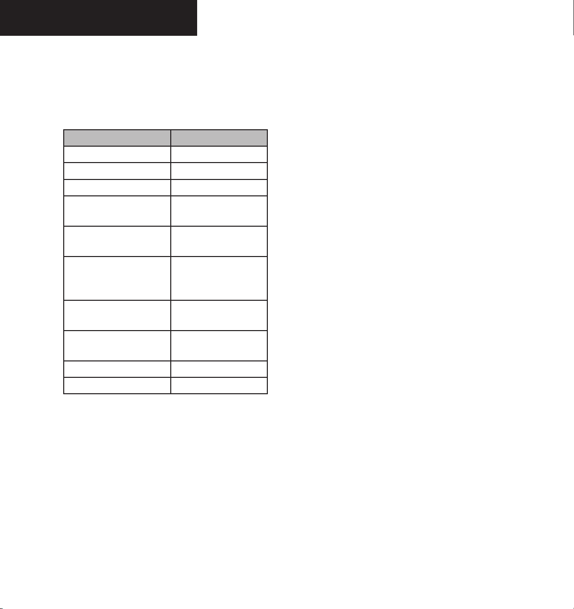
The EIS automatically switches to the default ENGINE
Page upon exceedance of specific parameters which are
listed in Table 7.1.1.
Parameter Exceedance
Fuel Flow GPH Greater than 27.4 GPH
Cylinder Head Temperature
Oil Temperature
Oil Pressure Less than 30 PSI or
Alternator 1 Load Greater than 100%
Alternator 2 Load Greater than 100%
Bus 1 Volts
Bus 2 Volts
Left Fuel Quantity Less than 13 GAL
Right Fuel Quantity Less than 13 GAL
Greater than 238 ºC
Greater than 116 ºC
greater than 100 PSI
(100 Amps)
(20 Amps) for 240s
or longer
Less than 24V or
greater the 30V
Less than 24V or
greater the 30V
Table 7.1.1 Auto Switch Default ENGINE Page
Garmin G1000 EIS Pilot’s Guide for the A36/G36 190-00550-00 Rev. A 7-2
Page 5

ENGINE INDICATION SYSTEM
7.2 ENGINE PAGE
Atop all three pages are two round dial gauges for
manifold pressure and revolutions per minute (RPM).
Beneath those gauges are horizontal bar indicators for fuel
flow, cylinder head temperature (CHT), oil temperature,
oil pressure, alternator amperage, bus voltage and fuel
quantity.
Manifold Pressure Gauge
The Manifold Pressure gauge displays the engine power
in inches of mercury (in Hg).
White (bottom of arc) – Below normal operating
•
range.
• Green – Normal operating range.
• White (top of arc) – Above normal operating
range.
Tachometer
The Tachometer displays propeller speed in revolutions
per minute (RPM).
• White – Below normal flight operating range.
• Green – Normal flight operating range.
• Red – Propeller overspeed.
Fuel Flow GPH Indicator
Fuel Flow Leaning Pointer
The Fuel Flow Leaning Pointer provides a leaning
reference for the pilot during a Max Power Climb (MPC)
or Cruise Climb. The pointer is displayed on the bottom
of the Fuel Flow indicator if the RPM exceeds 2530, or fuel
flow exceeds a specified value based on altitude during a
MPC or Cruise Climb (see table below).
Fuel Flow Leaning
Altitude
x1000ft
0 25.7 23.7
2 25.7 23.7
4 25.1 23.1
6 24.0 22.0
8 22.4 20.4
10 20.9 18.9
12 19.6 17.6
14 18.8 16.8
16 17.9 15.9
Table 7.2.1 Fuel Flow Leaning
Leaning
Max Power
Climb GPH
Leaning
Cruise Climb
GPH
The Fuel Flow indicator displays current fuel flow in
gallons per hour (GPH). The Fuel Flow indicator ranges
from 0 to 30.
• Green – Normal fuel flow.
• Red – Abnormal fuel flow.
190-00550-00 Rev. A Garmin G1000 EIS Pilot’s Guide for the A36/G36
7-3
Page 6

ENGINE INDICATION SYSTEM
CHT Indicator
The CHT (Cylinder Head Temperature) indicator
displays the temperature of the hottest cylinder in degrees
Fahrenheit. The number of the hottest cylinder appears
in the triangular pointer.
• Green – Normal
• Red – Warning
Oil Temperature Indicator
The Oil Temperature indicator displays the engine oil
temperature in degrees Fahrenheit.
• Green – Normal
• Yellow – Caution
• Red – Warning
Oil Pressure Indicator
The Oil Pressure indicator displays the pressure of the
oil supplied to the engine in pounds per square inch (PSI).
• Green – Normal
• Yellow – Caution
• Red – Warning (minimum and maximum)
Voltmeter
The Voltmeter displays the primary bus voltage. The
Voltmeter displays two (2) pointers which indicate the
voltage for Buses 1 and 2.
• Green – Normal
• Yellow – Caution
Fuel Qty GAL Indicator
The Fuel Quantity indicator displays the quantity of
fuel in the tanks, in gallons. Two (2) triangular pointers
labeled L (left) and R (right) indicate the number of gallons
in each fuel tank. The indicator ranges from 0 to 37 with
major tick marks at 0 and 37 and minor tick marks at 3
gallon intervals.
• Green – Normal
• Yellow – Caution
• Red – Warning (0 red tick mark)
Ammeter
The Ammeter displays the alternator load in amperes.
The Ammeter displays two (2) pointers which indicate the
load for Alternators 1 and 2.
• Green – Normal
• Yellow – Caution
Garmin G1000 EIS Pilot’s Guide for the A36/G36 190-00550-00 Rev. A 7-4
Page 7

Manifold
Pressure
Gauge
ENGINE INDICATION SYSTEM
Tachometer
Fuel Flow
Indicator
Oil Temperature
Indicator
Ammeter
Fuel Quantity
Indicator
Fuel Flow
Leaning Pointer
Cylinder Head
Temperature
Indicator
Oil Pressure
Indicator
Voltmeter
Figure 7.2.1 ENGINE Page
190-00550-00 Rev. A Garmin G1000 EIS Pilot’s Guide for the A36/G36
7-5
Page 8

ENGINE INDICATION SYSTEM
7.3 LEAN PAGE
The Lean Page is accessible by pressing the LEAN
softkey. A digital readout for fuel flow resides below
the tachometer. Beneath the fuel flow indication are bar
graphs and numeric readouts for exhaust gas temperature
(EGT) and cylinder head temperature (CHT) in degrees
Fahrenheit. The temperature deviation from peak resides
above the EGT graph. By default, the numeric readouts of
the EGT and CHT are associated with the hottest cylinder
and are graphically indicated in cyan (light blue). Color
coding for the EGT and CHT bar graphs is listed below:
• Cyan (light blue) – Selected Cylinder (EGT and
CHT)
• White – Normal (EGT and CHT)
• Yellow – Caution (CHT only)
• Red – Warning (CHT only)
Assist
leaning process. When a cylinder peaks, its peak is
represented by a single cyan line on the EGT bar graph.
The EGT readout for the peaked cylinder, indicated in cyan
(light blue), appears directly beneath the bar graph. The
system automatically switches to the first peak obtained
and displays the temperature deviation from peak in
degrees Celsius above the EGT bar graph.
softkey.
Cylinder Select
The CYL SLCT softkey can be utilized to obtain information about a particular cylinder. The CYL SLCT
softkey becomes disabled when:
The ASSIST softkey can be utilized to assist in the
NOTE: The pilot should follow the engine
manufacturer’s recommended leaning procedures
in the Pilot’s Operating Handbook (POH).
The ASSIST softkey is available by pressing the LEAN
To select the Assist function:
ASSIST
1. From the Lean Page, press the
to identify the peak.
softkey
• a particular cylinder turns yellow or red, until
the temperature decreases and returns to normal,
which is indicated by white on the bar graph
ASSIST softkey is pressed
• the
The CYL SLCT softkey is available by pressing the
LEAN softkey.
To monitor the desired cylinder(s):
1. From the Lean Page, press the
to cycle through each cylinder and view the EGT
and CHT.
CYL SLCT
Garmin G1000 EIS Pilot’s Guide for the A36/G36 190-00550-00 Rev. A 7-6
softkey
Page 9

Manifold
Pressure
Gauge
ENGINE INDICATION SYSTEM
Tachometer
Fuel Flow
Indicator
Cyan Line
Representing
Peak
EGT Readout
For Selected
Cylinder
CHT Readout
For Selected
Cylinder
Figure 7.3.1 LEAN Engine Page
Temperature
Deviation
From Peak
Exhaust Gas
Temperature
Bar Graph
Cylinder Head
Temperature
Bar Graph
190-00550-00 Rev. A Garmin G1000 EIS Pilot’s Guide for the A36/G36
7-7
Page 10

ENGINE INDICATION SYSTEM
7.4 SYSTEM PAGE
The System Page is accessible by pressing the SYSTEM
softkey. The readouts on this page are separated into three
categories: System, Fuel Calculation and Electrical.
System
• OIL ºC – Oil temperature in degrees Celsius
• OIL PSI – Oil pressure in pounds per square inch
Fuel Calculation
The fuel calculation portion of the System Page is based
on the fuel flow totalizer and displays the following:
• FFLOW GPH – Fuel flow in gallons per hour.
• GAL REM – Current fuel remaining in gallons as
set by the pilot and adjusted for fuel burn since
last set.
• GAL USED – Quantity of fuel used in gallons.
• ENDUR – Flight time remaining with fuel
onboard (HH:MM when more than an hour
remains).
• RANGE NM – Aircraft range in nautical miles.
To decrease the fuel totalizer quantity:
1. From the System Page, press the
softkey to obtain the desired number of gallons
remaining.
To increase the fuel totalizer quantity:
1. From the System Page, press the
softkey to obtain the desired number of gallons
remaining.
To reset the fuel totalizer:
1. From the System Page, press the
softkey. This also resets the GAL USED to
zero.
Electrical
• ALT LOAD – Alternator load in amperes
• BUS VOLTS – Primary bus voltage
NOTE: Refer to the Pilot’s Operating Handbook
(POH) for limitations.
DEC FUEL
INC FUEL
RST FUEL
Fuel calculations do not use the aircraft fuel quantity
indicators and are calculated from the last time the fuel
was reset.
If desired, the pilot can utilize the DEC FUEL, INC
FUEL and RST FUEL softkeys to adjust the amount of
fuel remaining for totalizer calculations.
• DEC FUEL – Decreases totalizer based fuel
quantity remaining in one gallon increments.
• INC FUEL – Increases totalizer based fuel
quantity remaining in one gallon increments.
• RST FUEL – Reset totalizer based fuel quantity
remaining relative to the aircraft fuel capacity.
Performing the fuel reset also sets the GAL USED
display to zero.
Garmin G1000 EIS Pilot’s Guide for the A36/G36 190-00550-00 Rev. A 7-8
Page 11

Manifold
Pressure
Gauge
Oil
Temperature
ENGINE INDICATION SYSTEM
Tachometer
Oil
Pressure
Fuel Flow
Gallons
Used
Range in
Nautical Miles
Voltage
Figure 7.4.1 SYSTEM Engine Page
Gallons
Remaining
Endurance
Amperes
190-00550-00 Rev. A Garmin G1000 EIS Pilot’s Guide for the A36/G36
7-9
Page 12

Garmin International, Inc.
1200 East 151st Street
Olathe, KS 66062, U.S.A.
p: 913.397.8200 f: 913.397.8282
Garmin AT, Inc.
2345 Turner Road SE
Salem, OR 97302, U.S.A.
p: 503.391.3411 f: 503.364.2138
Garmin (Europe) Ltd.
Unit 5, The Quadrangle
Abbey Park Industrial Estate
Romsey, SO51 9DL, U.K.
p: 44/0870.8501241 f: 44/0870.8501251
Garmin Corporation
No. 68, Jangshu 2nd Road
Shijr, Taipei County, Taiwan
p: 886/2.2642.9199 f: 886/2.2642.9099
www.garmin.com
190-00550-00 Rev. A © 2005 Garmin Ltd. or its subsidiaries
 Loading...