

Garmin G1000 User Manual

TM
G1000
Pilot’s Guide for Beechcraft 58/G58
Part Number Change Summary
190-00629-00
Rev. A
190-00629-00
Corrected figure numbering sequence in Section 7
Rev. B
Record of Revisions
Revision Date of Revision Revision Page Range Description
A
B
10/18/05
11/09/05
------------All
Initial release
Garmin G1000 Pilot’s Guide for Beechcraft 58/G58
190-00629-00 Rev. B

Copyright © 2005 Garmin Ltd. or its subsidiaries. All rights reserved.
This manual reflects the operation of System Software version 0500.01 or later.
COPYRIGHT
Garmin International, Inc., 1200 East 151st Street, Olathe, Kansas 66062, U.S.A.
Tel: 913/397.8200 Fax: 913/397.8282
Garmin AT, Inc., 2345 Turner Road SE, Salem, OR 97302, U.S.A.
Tel: 503/391.3411 Fax 503/364.2138
Garmin (Europe) Ltd., Unit 5, The Quadrangle, Abbey Park Industrial Estate, Romsey, Hampshire S051 9DL, U.K.
Tel: 44/0870.8501241 Fax: 44/0870.8501251
Garmin Corporation, No. 68, Jangshu 2nd Road, Shijr, Taipei County, Taiwan
Tel: 886/02.2642.9199 Fax: 886/02.2642.9099
Web Site Address: www.garmin.com
Except as expressly provided herein, no part of this manual may be reproduced, copied, transmitted, disseminated, downloaded or
stored in any storage medium, for any purpose without the express written permission of Garmin. Garmin hereby grants permission
to download a single copy of this manual and of any revision to this manual onto a hard drive or other electronic storage medium to
be viewed for personal use, provided that such electronic or printed copy of this manual or revision must contain the complete text
of this copyright notice and provided further that any unauthorized commercial distribution of this manual or any revision hereto is
strictly prohibited.
Garmin® is a registered trademark of Garmin Ltd. or its subsidiaries, and G1000™ is a trademark of Garmin Ltd. or its subsidiaries.
These trademarks may not be used without the express permission of Garmin.
Bendix/King® and Honeywell® are registered trademarks of Honeywell International, Inc., Silver Crown Plus™ is a trademark of
Honeywell International, Inc.; NavData® is a registered trademark of Jeppesen, Inc.; Stormscope® and Skywatch® are registered
trademarks of L-3 Communications; TCAD® is a registered trademark of Ryan International, Inc.; and XM® is a registered trademark
of XM Satellite Radio, Inc.
November 2005 190-00629-00 Rev. B Printed in the U.S.A.
190-00629-00 Rev. B
Garmin G1000 Pilot’s Guide for Beechcraft 58/G58
i

WARNINGS & CAUTIONS
WARNING:
Navigation and terrain separation must NOT be predicated upon the use of the terrain
function. The G1000 Terrain Proximity feature is NOT intended to be used as a primary reference for
terrain avoidance and does not relieve the pilot from the responsibility of being aware of surroundings
during flight. The Terrain Proximity feature is only to be used as an aid for terrain avoidance and is not
certified for use in applications requiring a certified terrain awareness system. Terrain data is obtained
from third party sources. Garmin is not able to independently verify the accuracy of the terrain data.
WARNING:
The displayed minimum safe altitudes (MSAs) are only advisory in nature and should not be
relied upon as the sole source of obstacle and terrain avoidance information. Always refer to current
aeronautical charts for appropriate minimum clearance altitudes.
WARNING:
The Garmin G1000, as installed in Beechcraft 58/G58 aircraft, has a very high degree of
functional integrity. However, the pilot must recognize that providing monitoring and/or self-test
capability for all conceivable system failures is not practical. Although unlikely, it may be possible for
erroneous operation to occur without a fault indication shown by the G1000. It is thus the responsibility
of the pilot to detect such an occurrence by means of cross-checking with all redundant or correlated
information available in the cockpit.
WARNING:
For safety reasons, G1000 operational procedures must be learned on the ground.
WARNING:
The altitude calculated by G1000 GPS receivers is geometric height above Mean Sea Level
and could vary significantly from the altitude displayed by pressure altimeters, such as the GDC 74A
Air Data Computer, or other altimeters in aircraft. GPS altitude should never be used for vertical
navigation. Always use pressure altitude displayed by the G1000 PFD or other pressure altimeters in
aircraft.
WARNING:
The Jeppesen database used in the G1000 system must be updated regularly in order to
ensure that its information remains current. Updates are released every 28 days. A database information
packet is included in the G1000 package. Pilots using an outdated database do so entirely at their own
risk.
Garmin G1000 Pilot’s Guide for Beechcraft 58/G58
190-00629-00 Rev. Bii

WARNINGS & CAUTIONS
WARNING:
The basemap (land and water data) must not be used for navigation, but rather only for nonnavigational situational awareness. Any basemap indication should be compared with other navigation
sources.
CAUTION:
The illustrations in this guide are only examples. Never use the G1000 to attempt to penetrate
a thunderstorm. Both the FAA Advisory Circular, Subject: Thunderstorms, and the Airman’s Information
Manual (AIM) recommend avoiding “by at least 20 miles any thunderstorm identified as severe or
giving an intense radar echo.”
CAUTION:
The United States government operates the Global Positioning System and is solely responsible
for its accuracy and maintenance. The GPS system is subject to changes which could affect the accuracy
and performance of all GPS equipment. Portions of the Garmin G1000 utilize GPS as a precision
electronic NAVigation AID (NAVAID). Therefore, as with all NAVAIDs, information presented by the
G1000 can be misused or misinterpreted and, therefore, become unsafe.
CAUTION:
To reduce the risk of unsafe operation, carefully review and understand all aspects of the
G1000 Pilot’s Guide documentation. Thoroughly practice basic operation prior to actual use. During
flight operations, carefully compare indications from the G1000 to all available navigation sources,
including the information from other NAVAIDs, visual sightings, charts, etc. For safety purposes, always
resolve any discrepancies before continuing navigation.
CAUTION:
CAUTION:
190-00629-00 Rev. B
The Garmin G1000 does not contain any user-serviceable parts. Repairs should only be made
by an authorized Garmin service center. Unauthorized repairs or modifications could void both the
warranty and the pilot’s authority to operate this device under FAA/FCC regulations.
The GDU 1040 PFD and MFD displays use a lens coated with a special anti-reflective coating
that is very sensitive to skin oils, waxes, and abrasive cleaners. CLEANERS CONTAINING AMMONIA
WILL HARM THE ANTI-REFLECTIVE COATING. It is very important to clean the lens using a clean, lintfree cloth and an eyeglass lens cleaner that is specified as safe for anti-reflective coatings.
Garmin G1000 Pilot’s Guide for Beechcraft 58/G58
iii

WARNINGS & CAUTIONS
NOTE:
All visual depictions contained within this document, including screen images of the G1000 panel
and displays, are subject to change and may not reflect the most current G1000 system. Depictions of
equipment may differ slightly from the actual equipment.
NOTE:
This device complies with part 15 of the FCC Rules. Operation is subject to the following two
conditions: (1) this device may not cause harmful interference, and (2) this device must accept any
interference received, including interference that may cause undesired operation.
NOTE:
There are several atmospheric phenomena in addition to nearby thunderstorms that can cause
isolated discharge points in the strike display mode. However, clusters of two or more discharge points
in the strike display mode do indicate thunderstorm activity if these points reappear after the screen
has been cleared. Avoid the clusters to avoid the thunderstorms. In the cell display mode, even a single
discharge point may represent thunderstorm activity and should therefore be avoided.
Garmin G1000 Pilot’s Guide for Beechcraft 58/G58
190-00629-00 Rev. Biv

WARRANTY
LIMITED WARRANTY
This Garmin product is warranted to be free from defects in materials or workmanship for two years from the date of purchase. Within this
period, Garmin will, at its sole option, repair or replace any components that fail in normal use. Such repairs or replacement will be made at no
charge to the customer for parts and labor, provided that the customer shall be responsible for any transportation cost. This warranty does not
cover failures due to abuse, misuse, accident, or unauthorized alterations or repairs.
THE WARRANTIES AND REMEDIES CONTAINED HEREIN ARE EXCLUSIVE AND IN LIEU OF ALL OTHER WARRANTIES EXPRESS OR IMPLIED OR
STATUTORY, INCLUDING ANY LIABILITY ARISING UNDER ANY WARRANTY OF MERCHANTABILITY OR FITNESS FOR A PARTICULAR PURPOSE,
STATUTORY OR OTHERWISE. THIS WARRANTY GIVES YOU SPECIFIC LEGAL RIGHTS, WHICH MAY VARY FROM STATE TO STATE.
IN NO EVENT SHALL GARMIN BE LIABLE FOR ANY INCIDENTAL, SPECIAL, INDIRECT OR CONSEQUENTIAL DAMAGES, WHETHER RESULTING
FROM THE USE, MISUSE, OR INABILITY TO USE THIS PRODUCT OR FROM DEFECTS IN THE PRODUCT. Some states do not allow the exclusion of
incidental or consequential damages, so the above limitations may not apply to you.
Garmin retains the exclusive right to repair or replace the unit or software, or to offer a full refund of the purchase price, at its sole discretion.
SUCH REMEDY SHALL BE YOUR SOLE AND EXCLUSIVE REMEDY FOR ANY BREACH OF WARRANTY.
To obtain warranty service, contact your local Garmin Authorized Service Center. For assistance in locating a Service Center near you, visit the
Garmin Web site at “http://www.garmin.com”
or contact Garmin Customer Service at 800-800-1020.
190-00629-00 Rev. B
Garmin G1000 Pilot’s Guide for Beechcraft 58/G58
v

WARRANTY
This page intentionally left blank.
Garmin G1000 Pilot’s Guide for Beechcraft 58/G58
190-00629-00 Rev. Bvi

TABLE OF CONTENTS
SECTION 1 SYSTEM OVERVIEW
1.1 Introduction .................................................... 1-1
1.2 System Description ......................................... 1-1
1.3 Optional Equipment ....................................... 1-3
1.4 PFD/MFD Controls .......................................... 1-4
1.5 Secure Digital Cards ....................................... 1-6
1.6 System Power-up ............................................ 1-7
1.7 Display Backlighting ....................................... 1-9
1.8 System Operation ........................................... 1-9
Normal Mode .............................................................1-9
Reversionary Mode ..................................................1-10
AFCS Preflight Test ...................................................1-10
AHRS Operation .......................................................1-11
SECTION 2 PRIMARY FLIGHT DISPLAY
2.1 Introduction .................................................... 2-1
2.2 Backlighting ................................................... 2-4
2.3 Softkey Function ............................................ 2-5
2.4 Flight Instruments .......................................... 2-9
Airspeed Indicator ......................................................2-9
Attitude Indicator .....................................................2-10
Altimeter ..................................................................2-12
Vertical Deviation/
Marker Beacon Annunciations ..................................
Vertical Speed Indicator ...........................................
Horizontal Situation Indicator ..................................2-15
Glideslope Indicator ....................2-14
2-14
2-14
2.5 Communication, Navigation, & Surveillance
(CNS) 2-21
Communication Frequency Window .........................
Navigation Frequency Window .................................
Navigation Status Bar ..............................................2-22
Transponder (XPDR) Status Bar ................................
2-21
2-21
2-22
2.6 Supplemental Flight Data ..............................2-23
Outside Air Temperature Box ....................................
2-23
System Time Box ......................................................2-23
Inset Map .................................................................2-23
Auxiliary Window Keys .............................................
Working with Menus ................................................
Auxiliary Windows ....................................................
2-26
2-27
2-27
2.7 Reversionary Mode .......................................2-42
2.8 Alerts and Annunciations ...............................2-43
Alerts Window ..........................................................
Annunciation Window ..............................................
Softkey Annunciations ..............................................
Terrain Awareness and Warning System (TAWS)
Annunciations (optional) ..........................................2-44
Traffic Annunciation .................................................
2-43
2-43
2-43
Alert
2-44
SECTION 3 NAV/COM
3.1 NAV/COM Description .................................... 3-1
Windows and Fields ...................................................
Radio Selection ...........................................................3-2
Controls ......................................................................3-3
Tuning Box .................................................................
Switching Between Radios .........................................3-4
Manually Tuning a Frequency .....................................
Radio Indicators .........................................................3-5
Volume .......................................................................
Frequency Transfer Arrow ...........................................
3-2
3-4
3-4
3-5
3-5
3.2 Com Operation ............................................... 3-6
Frequency Spacing ......................................................
Automatic Squelch .....................................................3-6
Selecting a COM Radio ...............................................3-6
Emergency Frequency (
Quick-Tuning and Activating
Stuck Microphone ......................................................3-7
121.500 MHz) ........................3-7
121.500 MHz .................3-7
3-6
3.3 NAV Operation ................................................ 3-8
Frequency
Morse Code Identifier .................................................
NAV
Range ........................................................3-8
3-8
Radio Selection for Navigation ...........................3-8
190-00629-00 Rev. B
Garmin G1000 Pilot’s Guide for Beechcraft 58/G58
vii

TABLE OF CONTENTS
DME TUNING .............................................................3-9
3.4 Frequency Auto-Tuning ..................................3-10
Auto-Tuning on the
Auto-Tuning on the
NRST – Nearest Airports Window .............................3-14
NRST – Nearest VOR Window ...................................3-15
Auto-Tuning on Approach Activation (NAV Frequencies) .
3-17
PFD ...........................................3-10
MFD ..........................................3-11
SECTION 4 TRANSPONDER
4.1 Transponder Description ................................. 4-1
Transponder Softkeys .................................................
Transponder Status Bar ..............................................
Mode S Features .........................................................
Traffic Information Service (TIS) ..................................
4-1
4-1
4-2
4-2
4.2 Operation ....................................................... 4-3
Mode Selection ..........................................................4-3
Code Selection ...........................................................4-4
IDENT Function ..........................................................4-5
SECTION 5 AUDIO PANEL
5.1 Audio Panel Description ................................. 5-1
Transceivers ................................................................
Mono/Stereo Headsets ...............................................5-2
Unmuted/Unswitched Inputs ......................................5-2
Front Panel Controls ...................................................
5-1
5-2
5.2 Operation ....................................................... 5-4
Power-up and Fail-Safe
Key A
nnunciators ........................................................5-4
Lighting ......................................................................5-4
Transceiver Keys .........................................................
Split COM Function ....................................................5-5
PA Function ................................................................
Speaker ......................................................................
Marker Beacon Receiver .............................................
Navigation Radios ......................................................5-7
Operation ..............................5-4
5-4
5-5
5-5
5-6
Intercom System (ICS) Isolation ..................................5-8
Intercom Volume and Squelch ....................................5-9
Entertainment Inputs ..................................................5-9
GDL 69A XM Radio System ......................................5-10
Master Avionics Squelch (MASQ) .............................
Digital Clearance Recorder with Playback ................5-11
Reversionary Mode ..................................................5-11
5-10
SECTION 6 ENGINE INDICATION SYSTEM
6.1 Introduction .................................................... 6-1
EIS Pages ....................................................................
EIS Indicators ..............................................................6-1
EIS Page Reversion .....................................................
6-1
6-2
6.2 Engine Page .................................................... 6-3
6.3 Lean Page ....................................................... 6-4
6.4 System Page ................................................... 6-6
SECTION 7 MULTI FUNCTION DISPLAY
7.1 Introduction .................................................... 7-1
Description .................................................................7-1
Optional Equipment ...................................................7-1
MFD Power-up ............................................................
MFD Backlighting .......................................................7-2
MFD Softkeys ............................................................
Reversionary Mode ....................................................7-2
Electronic Checklists (optional) ..................................7-3
MFD Page Groups ......................................................
Working With
Menus ..................................................7-8
7-2
7-2
7-7
7.2 Navigation Map Page ..................................... 7-9
Navigation Map Page Operations ............................
7-11
7.3 Traffic Map Page ............................................7-33
TIS Symbology ..........................................................7-34
Traffic Map Page Operations ....................................
7-34
7.4 Terrain Proximity Page ...................................7-37
Terrain Proximity Page Operations ...........................
Displaying Obstacle Data .........................................7-39
7-38
Garmin G1000 Pilot’s Guide for Beechcraft 58/G58
190-00629-00 Rev. Bviii

TABLE OF CONTENTS
7.5 TAWS (Optional) .............................................7-40
7.5 Direct-to Navigation ......................................7-47
Direct-to Navigation Operations ...............................7-48
7.6 Flight Plans ....................................................7-53
Active Flight Plan Page .............................................
Active Flight Plan Page Options ...............................
Flight Plan Catalog Page ..........................................
Flight Plan Catalog Page Operations .......................
Vertical Navigation (VNAV) Page ..............................
7-53
7-53
7-63
7-63
7-69
7.7 Procedures .....................................................7-71
Arrivals and Departures ............................................
Approaches ..............................................................7-72
G1000 Navigational Guidance for Approaches ........
Selecting Approaches ...............................................
7-71
7-72
7-73
7.8 Waypoint Page Group ....................................7-77
AIRPORT Information Page (INFO) ............................
Airport Frequency Information Field .........................
AIRPORT Information Page Options .........................
Departure Information Page (DP) .............................
Arrival Information Page (STAR) ...............................
Approach Information Page ......................................
Intersection Information Page ..................................7-88
NDB Information Page ..............................................
VOR Information Page ..............................................
User Waypoint Information Page ..............................
Creating User Waypoints ..........................................
Modifying User Waypoints .....................................
User Waypoint Information Page Options ...............
7-78
7-81
7-82
7-83
7-84
7-86
7-90
7-93
7-96
7-98
7-100
7-101
7.9 Auxiliary Page Group ...................................7-105
Trip Planning Page ..................................................
GPS Status Page .....................................................7-112
System Setup Page .................................................
System Status Page ................................................
7-105
7-116
7-126
7.10 Nearest Page Group ..................................7-127
Navigating to a Nearest Waypoint .........................
Nearest Intersections Page .....................................
7-128
7-132
Nearest NDB Page ..................................................7-133
Nearest VOR Page ..................................................
Nearest User Waypoint Page ..................................
Nearest Frequencies Page .......................................
Nearest Airspaces Page ..........................................
7-134
7-136
7-137
7-138
SECTION 8 AUTOMATIC FLIGHT CONTROL SYSTEM
8.1 Introduction .................................................... 8-1
AFCS Overview ...........................................................8-1
AFCS Controls ............................................................8-2
8.2 Flight Director Operation ............................... 8-4
Activating the Flight Director .....................................
AFCS Status Bar .........................................................8-5
Command Bars ...........................................................8-5
Flight Director Limitations ..........................................8-5
8-4
8.3 Flight Director Modes .................................... 8-6
Pitch Modes ...............................................................8-6
Roll Modes ...............................................................8-13
8.4 Autopilot and Yaw Damper Operation ..........8-17
Flight Control ...........................................................8-17
Engagement .............................................................8-18
Control W
Overspeed Protection ...............................................8-18
Disengagement ........................................................8-19
heel Steering ............................................8-18
8.5 Procedures .....................................................8-20
Departure .................................................................8-21
Intercepting a VOR ...................................................
Flying a Flight Plan/GPS Course ...............................8-23
Flight Level Change Descent ....................................8-24
Approaches ..............................................................8-25
8-22
8.6 AFCS Alerts ....................................................8-27
190-00629-00 Rev. B
Garmin G1000 Pilot’s Guide for Beechcraft 58/G58
ix

TABLE OF CONTENTS
SECTION 9 OPTIONAL EQUIPMENT
9.1 Optional Equipment ....................................... 9-1
9.2 Stormscope ..................................................... 9-2
Displaying Stormscope Lightning Data on the Nav Map .
9-2
Stormscope Page ........................................................
9-5
9.3 Traffic Advisory Systems ................................. 9-8
Introduction ................................................................9-8
L-3 SKYWATCH Traffic Advisory Systems (SKY497/
SKY899) ...................................................................9-10
9.4 Optional XM Weather ....................................9-12
Introduction ..............................................................9-12
GDL 69A Weather ....................................................
Weather Product Symbols ........................................
GDL 69A – XM Digital Audio Entertainment ............
XM Radio Page .........................................................9-26
GDL 69A Troubleshooting .........................................9-29
9-12
9-23
9-24
9.5 Airborne Weather Radar ................................9-31
SECTION 10 ANNUNCIATIONS AND ALERTS
10.1 Annunciations and Alerts .............................10-1
Alert Level Definitions ..............................................
Beechcraft 58/G58 Annunciations & Alerts ...............10-3
AFCS Alerts ...............................................................
TAWS ALERTS ...........................................................
TAWS System Status Annunciations .........................
G1000 System Annunciations ...................................
G1000 System Alert Messages .................................10-8
10-2
10-4
10-5
10-6
10-6
Appendix D G1000 Map Datums ..........................D-1
Appendix E General TIS Information .................... E-1
Introduction ................................................................E-1
TIS vs. TCAS ................................................................
TIS Limitations ............................................................E-1
E-1
Appendix F Map Symbols ..................................... F-1
Airport ........................................................................F-2
NAVAIDS ....................................................................
Basemap ....................................................................F-2
Traffic .........................................................................
Lightning Strike .......................................................... F-3
Miscellaneous ............................................................F-3
Line Symbols ..............................................................F-4
Obstacle database .................................................... G-1
Terrain Color Chart ....................................................
F-2
F-3
G-1
Appendix G G1000 System Specifications ...........G-2
GDU 1040 MFD & PFD ..............................................G-2
GMA 1347 Audio Panel .............................................
GIA 63 Integrated Avionics Units ..............................
GDC 74A Air Data Computer .....................................
GTX 33 Mode S Transponder .....................................
GEA 71 Engine/Airframe Unit .................................... G-3
GDL 69/69A Weather Data Link .................................
GRS 77 AHRS .............................................................
G-2
G-2
G-3
G-3
G-3
G-4
INDEX
Index ...................................................................... I-1
APPENDICES
Appendix A SD Card Use ......................................A-1
Aviation Database ..................................................... A-1
Terrain and Obstacle Databases ................................
A-1
Appendix B Abbreviations, Acronyms & NAV Terms ..
B-1
Appendix C Questions & Answers ........................C-1
Garmin G1000 Pilot’s Guide for Beechcraft 58/G58
190-00629-00 Rev. Bx

TM
G1000
System Overview

SYSTEM OVERVIEW
No. 1 GIA 63
Integrated Avionics Unit
System Inegration Processors
I/O Processors
VHF COM
VHF NAV/LOC
GPS
Glideslope
AFCS Mode Logic
Flight Director Calculations
Servo Communication
No. 2 GIA 63
Integrated Avionics Unit
System Integration Processors
I/O Processors
VHF COM
VHF NAV/LOC
GPS
Glideslope
Servo Communication
GTX 32
or GTX 33
Transponder
High-Speed Data Bus (Ethernet)
Reversionary
Control
GEA 71
Engine/Airframe
Unit
GDC 74A
Air Data
Computer
OAT
Airspeed
Altitude
Vertical Speed
GRS 77
AHRS
Attitude
Rate of Turn
Slip/Skid
GMU 44
Magnetometer
Heading
GPS Output
GPS Output
Reversionary
Control
GSA 81
Pitch Servo
Autopilot Calculations
GSA 81
Pitch Trim Servo
Autopilot Calculations
GSA 81
Roll Servo
Autopilot Calculations
GSA 81
Yaw Servo
Autopilot Calculations
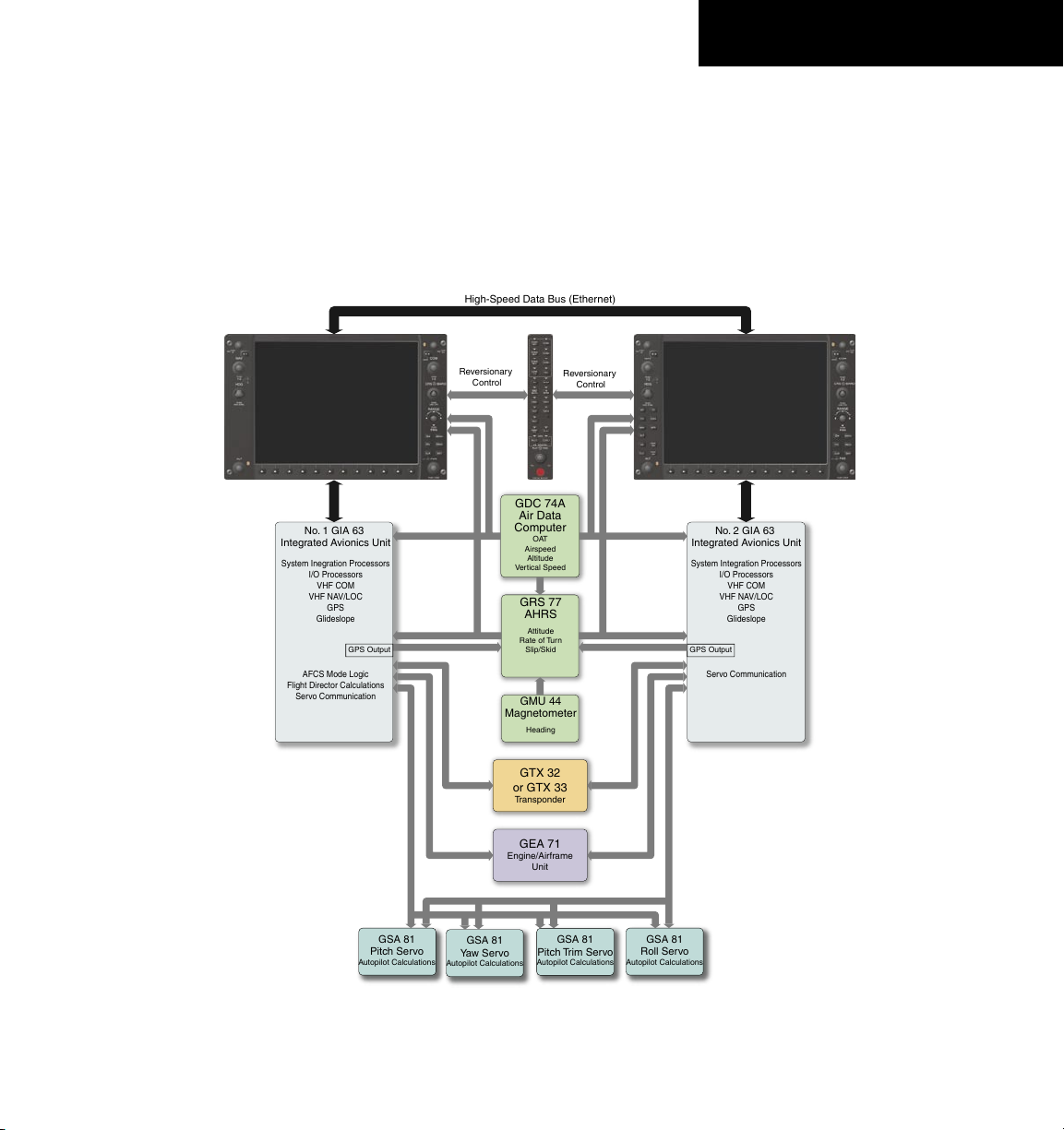
1.1 INTRODUCTION
This System Overview Pilot’s Guide provides a basic
description of the G1000 System as it pertains to the
Beechcraft 58/G58. The description includes the Garmin
Automatic Flight Control System (AFCS).
System. A G1000 system block diagram is given in
Figure 1-1. Refer to the Pilot’s Guide Appendices for LRU
specifications.
1.2 SYSTEM DESCRIPTION
This section gives a brief description of the G1000
190-00629-00 Rev. B Garmin G1000 Pilot’s Guide for the Beechcraft 58/G58
Figure 1-1 G1000 System Block Diagram
1-1

SYSTEM OVERVIEW
• GDU 1040/GDU 1043 – The G1000 features two
displays, the GDU 1040 and GDU 1043. The GDU
1040 is a 10.4-inch LCD display with 1024 x 768
resolution and is configured as a Primary Flight
Display. The GDU 1040 displays the Flight Director
command bars, system annunciations and alerts,
pilot-selectable references, and flight information.
The GDU 1043 is configured as a Multi Function
Display which contains the dedicated AFCS keys
and GPS/Navigation controls. The displays communicate with each other through a high-speed data
bus (HSDB) Ethernet connection. Each display is
also paired via an ethernet connection.
• GMA 1347 – Installed between the MFD and PFD,
the GMA 1347 integrates NAV/COM digital audio,
intercom system and marker beacon controls. The
GMA 1347 communicates with both GIA 63s using
an RS-232 digital interface. The GMA 1347 also
controls manual display reversionary mode.
• GIA 63 – There are two GIA 63s. The GIA 63 func-
tions as a main communication hub, linking all LRUs
with the PFD and the MFD displays. Each GIA 63
contains a GPS receiver, VHF COM/NAV/GS receivers, and system integration microprocessors. Each
GIA 63 is paired with a respective display through
an ethernet connection. The GIAs are not paired
together and do not communicate with each other
directly.
Each GIA 63 also contains the AFCS software
which controls the Flight Director. During normal
operation, the GRS 77 AHRS and GDC 74A Air Data
Computer send attitude and air data information
to the GIA 63s. This information, combined with
GPS and other system data, is used by the Flight
Director and Autopilot. Flight Director commands
are calculated within the #1 GIA 63 and are sent to
the PFD for display and mode annunciation. Flight
information is also sent to the GSA 81 servos for
Autopilot operation. A GIA #1 failure results in the
loss of the AFCS system. Any GIA 63 failure results
in loss of the Autopilot function.
• GRS 77 – The GRS 77 is an Attitude and Heading
Reference System (AHRS) that provides aircraft
attitude and heading information to both the
G1000 displays and the GIA 63s. The unit contains
advanced sensors, accelerometers and rate sensors.
In addition, the GRS 77 interfaces with both the
GDC 74A Air Data Computer and the GMU 44
Magnetometer. The GRS 77 also utilizes GPS signals
sent from the GIA 63. Attitude and heading information is sent using an ARINC 429 digital interface
to both GDU 1040s and GIA 63s. AHRS modes of
operation are discussed later in this document.
• GMU 44 – The GMU 44 Magnetometer measures
local magnetic field information. Data is sent to
the GRS 77 AHRS for processing to determine aircraft magnetic heading. This unit receives power
directly from the GRS 77 and communicates with
the GRS 77 using an RS-485 digital interface.
1-2
190-00629-00 Rev. BGarmin G1000 Pilot’s Guide for the Beechcraft 58/G58

SYSTEM OVERVIEW
• GDC 74A – The GDC 74A Air Data Computer
processes information from the pitot/static system
as well as the outside air temperature (OAT) sensor.
The GDC 74A provides pressure altitude, airspeed,
vertical speed and OAT information to the G1000
system, and communicates with the GIA 63s,
GDU 1040s and GRS 77 using an ARINC 429 digital
interface.
• GEA 71 – The GEA 71 receives and processes signals
from the engine and airframe sensors. Sensor types
include engine temperature and pressure sensors as
well as fuel measurement and pressure sensors. The
GEA 71 communicates with both GIA 63s using an
RS-485 digital interface.
• GTX 33 – The GTX 33 is a solid-state, Mode-S
transponder that provides Modes A, C and S operation. The GTX 33 is controlled through the PFD
and communicates with both GIA 63s through an
RS-232 digital interface.
• SA 81 AFCS Servos – Four GSA 81 servos are
used for automatic control of the aircraft flight
control surfaces. One servo is used for the each of
the following:
Each servo moves its respective aircraft control
surface in response to commands generated by
internal servo calculations. For pitch trim, the servo
positions the aircraft pitch trim surface in response
to commands generated by automatic and manual
electric pitch trim calculations. Calculations are
performed using data sent through the common
serial data bus from the GIA 63. Manual Electric
Pitch Trim is also provided in response to the Manual
Electric Trim (
MET) switch.
1.3 OPTIONAL EQUIPMENT
This System Overview only covers the baseline
configuration of the G1000. Descriptions and procedures
relating to optional equipment is covered in the G1000
Optional Equipment section. Consult a Garmin authorized
service center for optional equipment availability and
configuration.
• Pitch
• Roll
• Pitch Trim
• Yaw
190-00629-00 Rev. B Garmin G1000 Pilot’s Guide for the Beechcraft 58/G58
1-3
SYSTEM OVERVIEW
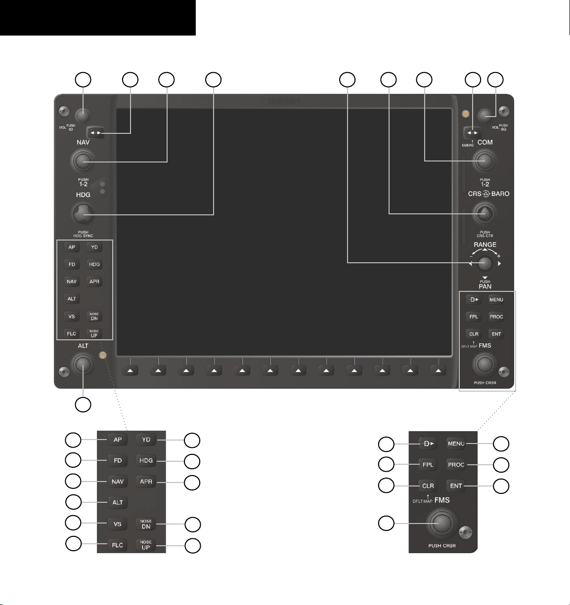
1.4 PFD/MFD CONTROLS
3
421 6
5
7
8
9
1-4
18
19
20
21
22
23
17
MFD Only
24
25
26
27
28
Figure 1-2 PFD/MFD Controls
10
11
12
13
14
15
16
190-00629-00 Rev. BGarmin G1000 Pilot’s Guide for the Beechcraft 58/G58

SYSTEM OVERVIEW
Functionality of the PFD and MFD controls are the
same with the exception of the dedicated autopilot keys
located only on the MFD bezel.
(1) NAV VOL/ID Knob – Controls the NAV audio level.
Press to toggle the Morse code identifier ON and OFF.
Volume level is shown in the field as a percentage.
(2) NAV Frequency Toggle Key – Toggles the standby
and active NAV frequencies.
(3) Dual NAV Knob – Tunes the MHz (large knob)
and kHz (small knob) standby frequencies for the NAV
receiver. Press to toggle the tuning cursor (light blue
box) between the NAV1 and NAV2 fields.
(4) Heading Knob – Turn to manually select a heading
on the HSI. When pressed, it synchronizes the heading
bug with the compass lubber line. Selected Heading
provides the heading reference to the Flight Director
while operating in Heading Select mode.
(5) Joystick – Changes the map range when rotated.
Activates the map pointer when pressed.
(6) CRS/BARO Knob – The large knob sets the altimeter
barometric pressure and the
small knob adjusts the
course. The course is only adjustable when the HSI is in
VOR1, VOR2, or OBS/SUSP mode. Pressing this knob
centers the CDI on the currently selected VOR.
Selected
Course provides course reference to the Flight Director
when operating in Navigation and Approach modes.
(7) Dual COM Knob – Tunes the MHz (large knob)
and kHz (small knob) standby frequencies for the COM
transceiver. Pressing this knob toggles the tuning cursor
(light blue box) between the COM1 and COM2 fields.
(8) COM Frequency Toggle Key – Toggles the standby
and active COM frequencies. Pressing and holding this
key for two seconds automatically tunes the emergency
frequency (121.5 MHz) in the active frequency field.
(9) COM VOL/SQ Knob – Controls COM audio level.
Pressing this knob turns the COM automatic squelch ON
and OFF. Audio volume level is shown in the field as a
percentage.
(10) Direct-to Key – Allows the user to enter a
destination waypoint and establish a direct course to the
selected destination (specified by the identifier, chosen
from the active route, or taken from the map cursor
position).
(11) FPL Key – Displays the active Flight Plan Page for
creating and editing the active flight plan, or for accessing
stored flight plans.
(12) CLR Key (DFLT MAP) – Erases information,
cancels an entry, or removes page menus. To display the
Navigation Map Page immediately, press and hold CLR
(MFD only).
(13) Dual FMS Knob – Used to select the page to be
viewed (only on the MFD). The large knob selects a page
group (MAP, WPT, AUX, NRST), while the small knob
selects a specific page within the page group. Pressing
the small knob turns the selection cursor ON and OFF.
When the cursor is ON, data may be entered in the
different windows using the small and large knobs. The
large knob is used to move the cursor on the page, while
the small knob is used to select individual characters
for the highlighted cursor location. When the G1000
displays a list that is too long for the display screen, a
scroll bar appears along the right side of the display,
indicating the availability of additional items within the
selected category. Press the FMS/PUSH CRSR knob to
activate the cursor and turn the large FMS knob to scroll
through the list.
MENU Key – Displays a context-sensitive list of
(14)
options. This list allows the user to access additional
features, or to make setting changes that relate to certain
pages.
(15)
PROC Key – Selects approaches, departures and
arrivals from the flight plan. If a flight plan is used,
available procedures for the departure and/or arrival
airport are automatically suggested. If a flight plan is not
used, the desired airport and the desired procedure may
be selected. This key selects IFR departure procedures
190-00629-00 Rev. B Garmin G1000 Pilot’s Guide for the Beechcraft 58/G58
1-5

SYSTEM OVERVIEW
(DPs), arrival procedures (STARs) and approaches (IAPs)
from the database and loads them into the active flight
plan.
(16) ENT Key – Accepts a menu selection or data entry.
This key is used to approve an operation or complete data
entry. It is also used to confirm selections and information
entries.
(17) Dual ALT Knob – Sets the reference altitude in
the box located above the Altimeter. The large knob
selects the thousands, while the small knob selects the
hundreds. Selected altitude provides an altitude setting
for the Altitude Capture/Hold mode, in addition to the
standard G1000 altitude alerter function.
(18) AP Key – Engages/disengages the Autopilot and
Flight Director in the default vertical and lateral modes.
(19) FD Key – Activates/deactivates the Flight Director
only. Pressing the FD key turns on the Flight Director in
the default vertical and lateral modes. Pressing the FD
key again deactivates the Flight Director and removes the
command bars, unless the Autopilot is engaged. If the
Autopilot is engaged, the FD key is disabled.
(20) NAV Key – Selects/deselects the Navigation mode.
(21) ALT Key – Selects/deselects the Altitude Hold
mode.
(22) VS Key – Selects/deselects the Vertical Speed mode.
(23) FLC Key – Selects/deselects the Flight Level Change
mode.
(24) YD Key – Engages/disengages the Yaw Damper.
(25) HDG Key – Selects/deselects the Heading Select
mode.
(26) APR Key – Selects/deselects the Approach mode.
(27, 28) NOSE UP/NOSE DN Keys – Controls the
active pitch reference for the Pitch Hold, Vertical Speed,
and Flight Level Change modes.
1.5 SECURE DIGITAL CARDS
The GDU 1040 data card slots use Secure Digital (SD)
cards. SD cards are used for aviation database updates
and terrain database storage.
To install an SD card:
1. Insert the SD card in the SD card slot located
on the right side of the display bezel (the front
of the card should be flush with the face of the
display bezel).
To remove an SD card:
1. Gently press on the SD card to release the
spring latch and eject the card.
NOTE: Refer to the Pilot’s Guide Appendices for
instructions on updating the aviation database.
1-6
190-00629-00 Rev. BGarmin G1000 Pilot’s Guide for the Beechcraft 58/G58
SYSTEM OVERVIEW
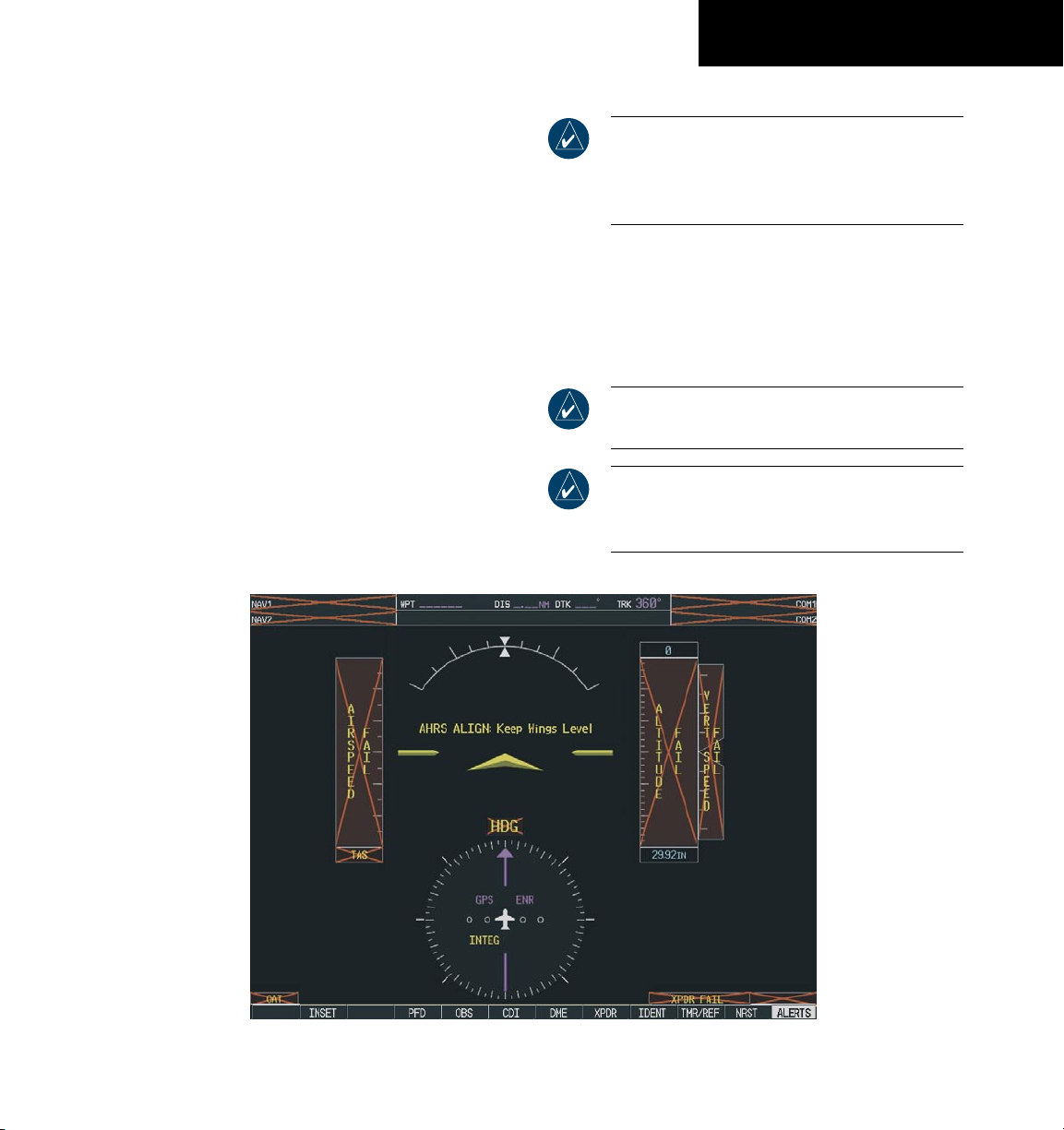
1.6 SYSTEM POWER-UP
The G1000 system is integrated with the aircraft
electrical system and receives power directly from electrical
busses. The Garmin G1000 PFD/MFD and supporting
sub-systems include both power-on and continuous builtin test features that exercise the processor, RAM, ROM,
external inputs and outputs to provide safe operation.
While the system begins to initialize, test annunciations
are displayed to the pilot at power-up, as shown in the
figure below. All system annunciations should be cleared
within one (1) minute of power-up. The GMA 1347 also
annunciates all bezel lights briefly upon power-up.
NOTE: Refer to the Beechcraft 58/G58 Pilot’s
Operating Handbook (POH) for specific procedures
concerning avionics power application and
emergency power supply operation.
On the PFD, the AHRS system displays the ‘AHRS
ALIGN: Keep Wings Level’ message and begins to initialize.
The AHRS should display valid attitude and heading fields
within one (1) minute of power-up. The AHRS can align
itself both while taxiing and during level flight.
NOTE: Refer to the Appendices for AHRS
initialization bank angle limitations.
NOTE: See the Annunciations and Alerts Section
for additional information regarding system
annunciations and alerts.
Figure 1-3 PFD Initialization Display
190-00629-00 Rev. B Garmin G1000 Pilot’s Guide for the Beechcraft 58/G58
1-7

SYSTEM OVERVIEW
When the MFD powers up, the MFD Power-up Page
displays the following information:
• System version
• Copyright
• Checklist filename
• Land database name and version
• Obstacle database name and version
• Terrain database name and version
• Aviation database name, version and effective
dates
When this information has been reviewed for currency
(to ensure that no databases have expired), the pilot is
prompted to continue. Current database information is
displayed with the valid operating dates, cycle number
and database type.
Press the
ENT key to acknowledge this information
and proceed to the Navigation Map Page.
1-8
Figure 1-4 MFD Power-up Page
190-00629-00 Rev. BGarmin G1000 Pilot’s Guide for the Beechcraft 58/G58
SYSTEM OVERVIEW
1.7 DISPLAY BACKLIGHTING
The G1000 PFD and MFD displays use photocell
technology to automatically adjust for ambient lighting
conditions. Photocell calibration curves are pre-configured
to optimize display appearance through a broad range
of cockpit lighting conditions. The PFD, MFD, and
GMA 1347 bezel/key lighting is typically controlled
directly by the existing instrument panel dimmer bus.
If desired, the PFD and MFD display backlighting can
be adjusted manually. The PFD, MFD and GMA 1347
bezel/key brightness can also be adjusted manually. The
GMA 1347 bezel/key brightness is directly tied to the
MFD bezel/key adjustment.
NOTE: Refer to the Primary Flight Display
section for instructions on adjusting backlighting
manually.
1.8 SYSTEM OPERATION
NORMAL MODE
The PFD and MFD are connected together on a single
Ethernet bus, allowing for high-speed communication
between the two units. Each GIA 63 is connected to a
single display This allows the units to share information,
thus enabling true system integration.
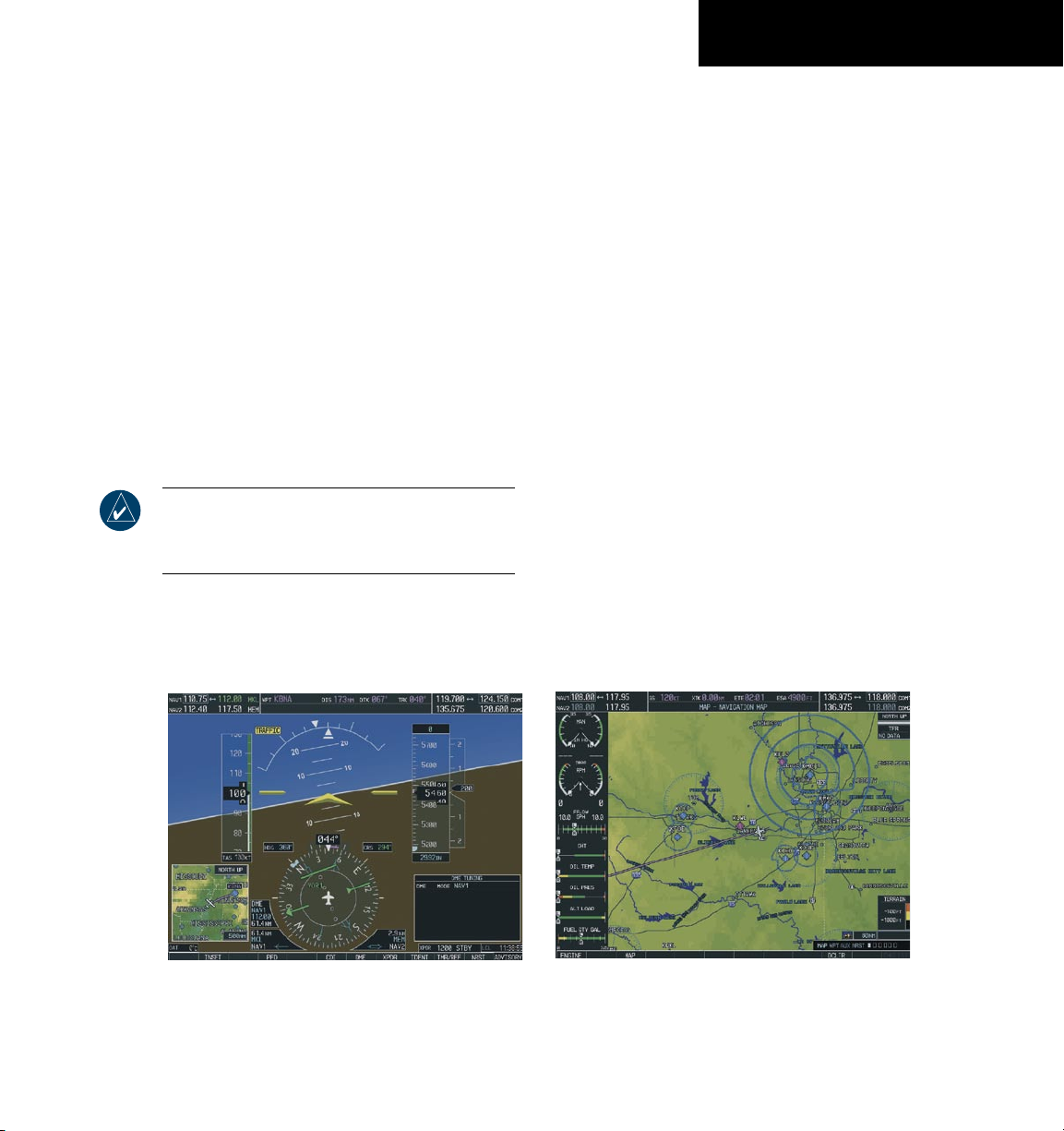
In normal operating mode, the PFD displays graphical
flight instrumentation instead of the traditional gyro
instruments. Attitude, heading, airspeed, altitude
and vertical speed are all shown on one display. The
MFD shows a full-color moving map with navigation
information. Both displays offer control for COM and NAV
frequency selection, as well as for the heading, course/baro
and altitude reference functions. On the left of the MFD
display, the Engine Indication System (EIS) cluster shows
engine and airframe instrumentation. Figure 1-5 gives an
example of the G1000 system in normal mode.
Figure 1-5 Normal Mode
190-00629-00 Rev. B Garmin G1000 Pilot’s Guide for the Beechcraft 58/G58
1-9
SYSTEM OVERVIEW
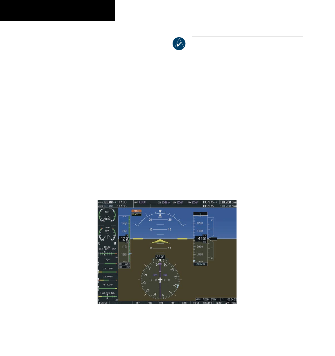
REVERSIONARY MODE
Should a failure occur in either display, the G1000
automatically enters reversionary mode. In reversionary
mode, all important flight information is shown on the
remaining display. An example of reversionary mode
entry due to a failed PFD is shown in Figure 1-6.
If a display fails, the GIA 63-GDU 1040 Ethernet
interface is cut off. Thus, the GIA can no longer
communicate with the remaining display, and the NAV
and COM functions provided to the failed display by the
GIA are flagged as invalid on the remaining display. The
system reverts to using backup paths for the GRS 77, GDC
74A, GEA 71 and GTX 33, as required. The change to
backup paths is completely automated for all LRUs, and
no pilot action is required.
NOTE: The system alerts the pilot when backup
paths are utilized by the LRUs. Refer to the
Annunciations and Alerts Pilot’s Guide for further
information regarding these and other system
alerts.
Reversionary mode may also be manually activated by
the pilot if the system fails to detect a display problem.
Reversionary mode is activated manually by pressing
the red DISPLAY BACKUP button at the bottom of
the GMA 1347 Audio Panel. Pressing this button again
deactivates reversionary mode.
AFCS PREFLIGHT TEST
When power is applied to the G1000, the AFCS system
starts preflight system tests. ‘PFT’ is annunciated on the
PFD at the AFCS System Status field. The Autopilot
disconnect aural alert tone sounds at the end of the test
and the ‘PFT’ annunciation disappears.
1-10
Figure 1-6 Reversionary Mode
190-00629-00 Rev. BGarmin G1000 Pilot’s Guide for the Beechcraft 58/G58
SYSTEM OVERVIEW
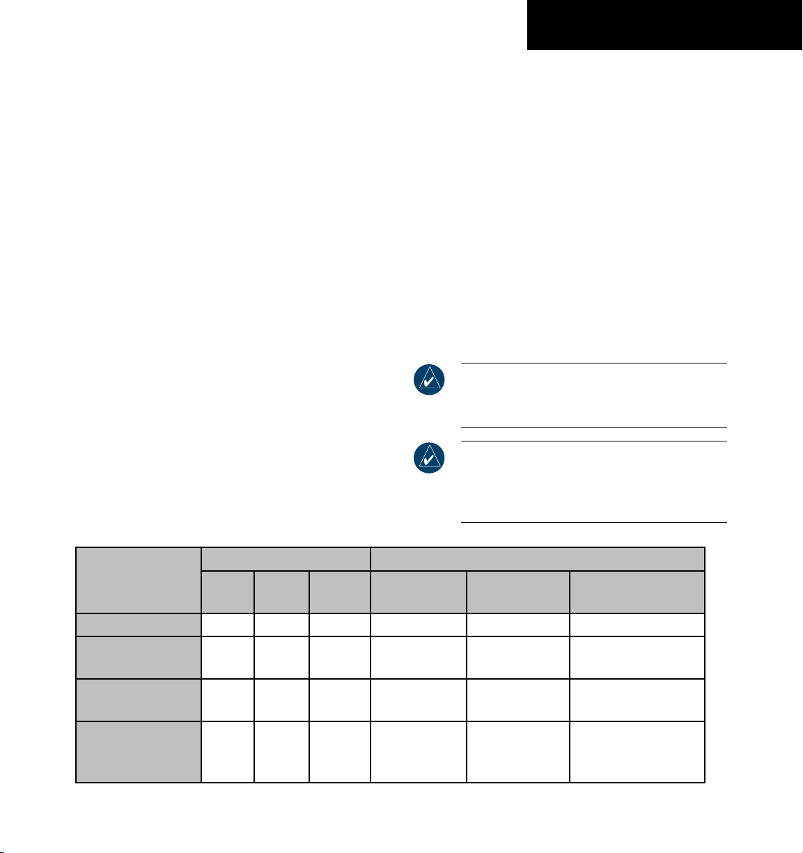
AHRS OPERATION
In addition to using internal sensors, the GRS 77
AHRS uses GPS information, magnetic field data and
air data to assist in attitude/heading calculations. In
normal (primary) mode, the AHRS relies upon GPS and
magnetic field measurements. If either of these external
measurements is unavailable or invalid, the AHRS uses air
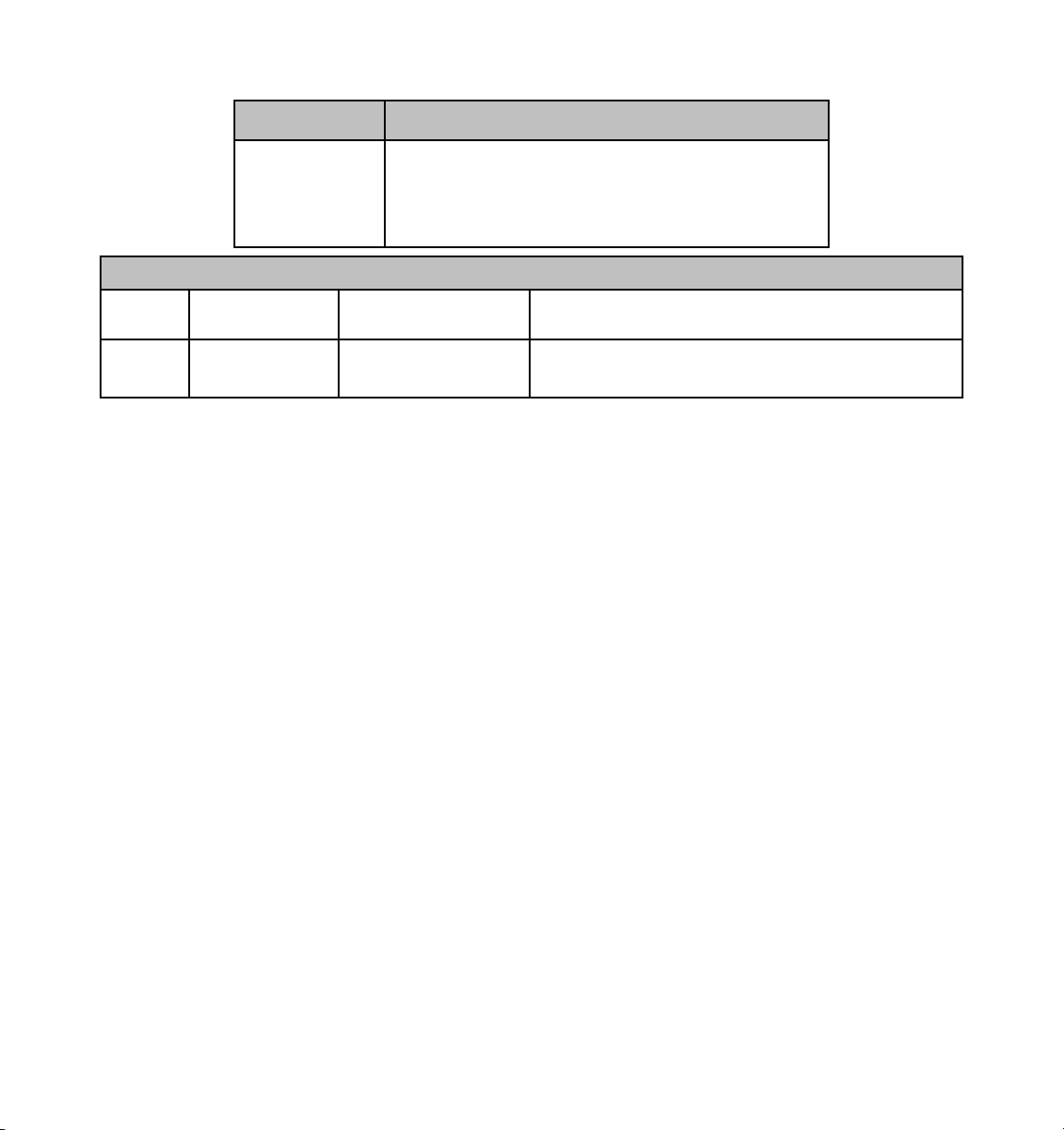
data information for attitude determination. Four AHRS
modes of operation are available (see table below) and
depend upon the combination of available sensor inputs.
Loss of air data, GPS, or magnetometer sensor inputs is
communicated to the pilot by message advisory alerts.
GPS Input Failure
The G1000 system provides two sources of GPS
information. If a single GPS receiver fails, or if the
information provided from one of the GPS receivers is
unreliable, the AHRS seamlessly transitions to using the
other GPS receiver. An alert message informs the pilot of
the use of the backup GPS path. If both GPS inputs fail,
the AHRS continues to operate in reversionary ‘No GPS’
mode so long as the air data and magnetometer inputs are
available and valid.
Air Data Input Failure
A failure of the air data input has no effect on AHRS
output while AHRS is operating in normal/primary mode.
A failure of the air data input while the AHRS is operating
in reversionary ‘No GPS’ mode results in invalid attitude
and heading information on the PFD (as indicated by red
‘X’ flags).
Magnetometer Failure
If the magnetometer input fails, the AHRS transitions
to one of the reversionary ‘No Magnetometer’ modes and
continues to output valid attitude information. However,
the heading output on the PFD does become invalid (as
indicated by a red ‘X’).
NOTE: Please refer to the Annunciations and
Alerts Pilot’s Guide for specific AHRS alert
information.
NOTE: Pilots should be aware that aggressive
maneuvering in any of the three reversionary
mod es li sted below can degrade A HRS
accuracy.
Available AHRS Functions Available Sensor Inputs
AHRS Mode
Pitch Roll
GPS Input
(At least one)
GMU 44
Magnetometer
Normal/Primary X X X X X X
Reversionary:
No GPS
Reversionary:
No Magnetometer
X X X - X X
X X - X - X
Reversionary:
No Magnetometer
X X - X - -
No Air Data
190-00629-00 Rev. B Garmin G1000 Pilot’s Guide for the Beechcraft 58/G58
GDC 74A
Air Data Computer
1-11

SYSTEM OVERVIEW
This page intentionally left blank
1-12
190-00629-00 Rev. BGarmin G1000 Pilot’s Guide for the Beechcraft 58/G58

TM
G1000
Primary Flight Display
SECTION 2 PRIMARY FLIGHT DISPLAY

Garmin G1000 Pilot’s Guide for Beechcraft 58/G58 190-00629-00 Rev. B

PRIMARY FLIGHT DISPLAY
2.1 INTRODUCTION
WARNING: In the event that the airspeed, attitude,
altitude, or heading indications become unusable,
please refer to the backup instruments.
This section describes the major features of the G1000
Primary Flight Display (PFD) as installed on Beechcraft 58/
G58 aircraft. Information is displayed using the G1000’s
two 10.4-inch color flat-panel displays. During normal
operation, the left display is configured as a Primary Flight
Display.
The PFD provides increased situational awareness by
replacing the traditional instrument “six pack” on the
pilot’s panel with an easy-to-scan display that provides
a large horizon and airspeed, attitude, altitude, vertical
speed, navigation, communication, annunciation,
terrain, traffic, and lightning (optional) information. The
PFD also controls the operation of the transponder, the
selection of NAV/COM frequencies, audio volume, and
many navigation features. The operation of these features
is explained in other supporting sections.
The G1000 system controls were designed so that,
regardless of which seat the pilot is flying from, the aircraft
can be flown with one hand and the controls manipulated
with the other hand.
The PFD displays the following:
• Flight Instruments (2.4)
– Airspeed Indicator with True Airspeed Box
– Attitude and Slip/Skid Indicators
– Altimeter with Selected Altitude and Barometric
Setting Boxes
– Vertical Deviation/Glideslope Indicator
– Marker Beacon Annunciations
– Vertical Speed Indicator
– Horizontal Situation Indicator
- Turn Rate Indicator
- Bearing Pointers and Information Windows
- DME Information Window (optional)
- Radio Tuning Window (if DME equipped)
- Navigation Source
• Communication, Navigation, and Surveillance
(CNS) Information (2.5)
– Communication Frequency Window
– Navigation (NAV) Frequency Window
– Navigation Status Bar
– Transponder Status Bar
• Supplemental Flight Data (2.6)
– Outside Air Temperature Box
– System Time Box
– Inset Map
– Auxiliary Windows
- Timer/References Window
- Nearest Airports Window
- Direct-to Window
- Flight Plan Window
- Procedures Window
• Alerts and Annunciations (2.8)
– Alerts Window
– Annunciation Window
– Terrain Awareness and Warning System (TAWS)
Alert Annunciations
– Traffic Annunciation
190-00629-00 Rev. B Garmin G1000 Pilot’s Guide for Beechcraft 58/G58
2-1
PRIMARY FLIGHT DISPLAY
1
2
3
4
5
6
19
18
17
16
7
15
14
13
12
11
10
9
8
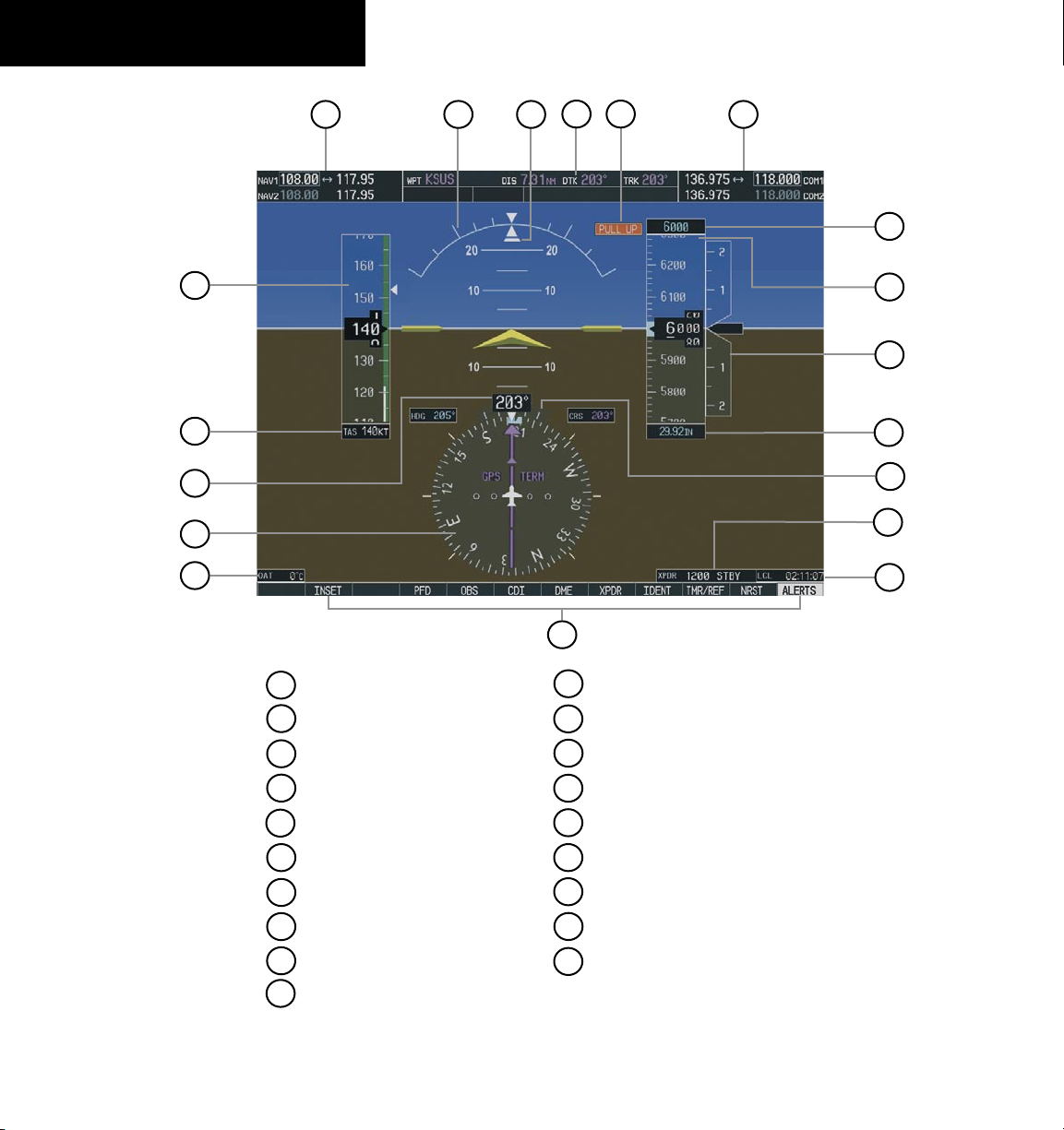
1
NAV Frequency Window
2
Airspeed Indicator
3
True Airspeed Box
4
Heading Box
5
Horizontal Situation Indicator
6
Outside Air Temperature Box
7
Softkeys
8
System Time Box
9
Transponder Status Bar
10
Turn Rate Indicator
Figure 2-1 Default PFD Information
11
Barometric Setting Box
12
Vertical Speed Indicator
13
Altimeter
14
Selected Altitude Box
15
COM Frequency Window
16
TAWS Alert Annunciation
17
Navigation Status Bar
18
Slip/Skid Indicator
19
Attitude Indicator
190-00629-00 Rev. BGarmin G1000 Pilot’s Guide for Beechcraft 58/G582-2
 Loading...