

Page 1
TM
G1000
AFCS Pilot’s Guide for
Beechcraft A36/G36
Page 2
Record of Revisions
Revision Date of Revision Revision Page Range Description
A
B
07/20/05
07/28/05
9-1 – 9-29
9-1 – 9-29
Initial release
Go Around button description change
Garmin G1000 AFCS Pilot’s Guide for Beechcraft A36/G36
190-00609-00 Rev. B
Page 3
INTRODUCTION
9.1 INTRODUCTION
pitch, roll, and pitch trim GSA 81 servos and provides:
NOTE: This Pilot’s Guide assumes that the reader
is already familiar with the G1000 Integrated
Cockpit System. Refer to the G1000 Cockpit
Reference Guide and G1000 Pilot’s Guides
for further information concerning the G1000
system.
IMPORTANT: The information contained in this
guide is always superseded by the approved
Airplane Flight Manual Supplement.
AFCS OVERVIEW
The GFC 700 is a digital Automatic Flight Control System (AFCS) which is fully integrated within the G1000
system avionics architecture. The System Overview located near the front of this binder provides a block diagram
to support this system description. The GFC 700 AFCS is
made up of the following Line Replaceable Units (LRUs):
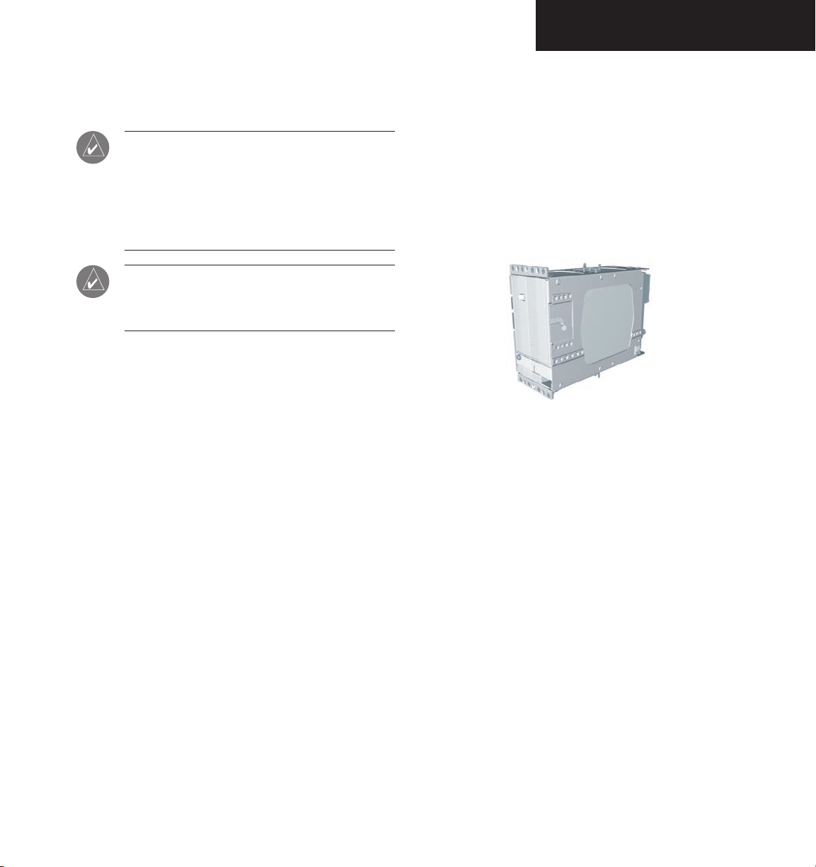
• GDU
• GDU 1043 Multi-Function Display (MFD)
• GIA 63 Integrated Avionics Units (2)
• GSA
• GSM 85 Servo Mounts (4)
The GFC 700 AFCS system can be divided into three
main operating functions:
1040 Primary Flight Display (PFD)
81 Servos (4)
the GSA 81 yaw servo and includes self monitoring.
GIA 63 Integrated Avionics Units
trols the Flight Director. During normal operation, the
GRS 77 AHRS and GDC 74A Air Data Computer send
attitude and air data information to the GIA 63s. This
information, combined with GPS and other system data,
is used by the Flight Director and Autopilot. Flight Director commands are calculated within the #1 GIA 63 and
are sent to the PFD for display and mode annunciation.
Flight information is also sent to the GSA 81 servos for
Autopilot operation. A GIA #1 failure results in the loss
of the AFCS system. Any GIA 63 failure results in loss of
the Autopilot, Manual Electric Trim, and the Yaw Damper
functions.
Autopilot — Autopilot operation occurs within the
• Automatic Flight Control
• Servo Monitoring
Yaw Damper — Yaw damper operation is provided by
Each GIA 63 contains the AFCS software which con-
Flight Director — Flight Director operation takes
place within the #1 GIA 63 and the GDU 1040 PFD. The
Flight Director provides the system with:
• Command Bars showing Pitch/Roll Guidance
• Pitch/Roll Mode Selection & Processing
• Autopilot Communication
190-00609-00 Rev. B
Garmin G1000 AFCS Pilot’s Guide for Beechcraft A36/G36
9-1
Page 4
INTRODUCTION
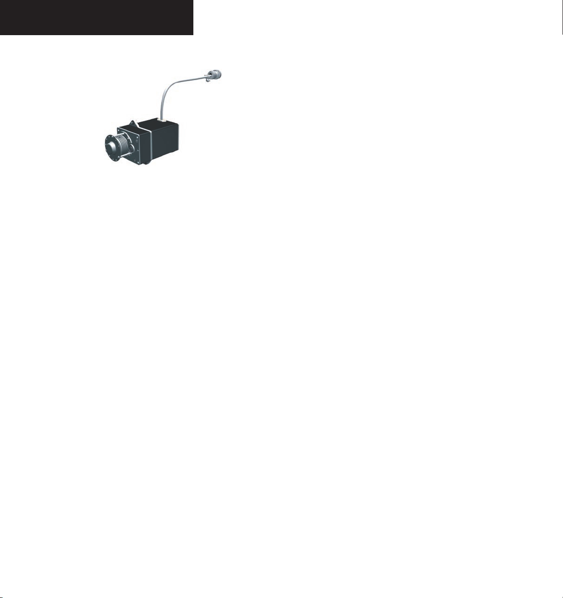
GSA 81 AFCS Servos (4)
Four GSA 81 servos are used for automatic control of
the aircraft flight control surfaces. One servo is used for
the each of the following:
• Pitch
• Roll
• Pitch Trim
• Yaw
Each servo moves its respective aircraft control surface
in response to commands generated by internal servo cal
culations. For pitch trim, the servo positions the aircraft
pitch trim surface in response to commands generated
by automatic and manual electric pitch trim calculations.
Calculations are performed using data sent through the
common serial data bus from the GIA 63. Manual electric
pitch trim is also provided in response to the Manual Electric Trim (
MET) switch.
GSM 85 Servo Mounts (4)
The GSM 85 servo mounts are used to connect the
servos to the aircraft control system. They contain a spiral capstan which connects via a bridle cable to the main
aircraft control cables. There is also a slip clutch to limit
overpower forces in the unlikely event of a mechanical
jam. An engage clutch is used to disconnect the capstan
from the servo when the AFCS is disengaged.
Dedicated AFCS Controls
Refer to Figure 2.3.1 located in the System Overview.
The GDU 1043 MFD has the following dedicated AFCS
keys located on the lower left side of the bezel:
• AP Key
– Engages/disengages the Autopilot
• FD Key – Activates/deactivates the Flight Director
only
Pressing the
FD key turns on the Flight Director in the default vertical and lateral modes.
Pressing the
FD key again deactivates the
Flight Director and removes the command
bars, unless the Autopilot is engaged. If the
Autopilot is engaged, the FD key is disabled.
• NAV Key
• ALT Key
– Selects/deselects the Navigation mode
– Selects/deselects the Altitude Hold
mode
• VS Key – Selects/deselects the Vertical Speed
mode
• FLC Key
– Selects/deselects the Flight Level
Change mode
• YD Key
• HDG Key
– Engages/disengages the Yaw Damper
– Selects/deselects the Heading Select
mode
• APR Key – Selects/deselects the Approach mode
• NOSE UP/NOSE DN Keys – Controls the active
pitch reference for the Pitch Hold, Vertical Speed,
and Flight Level Change modes
9-2
Garmin G1000 AFCS Pilot’s Guide for Beechcraft A36/G36
190-00609-00 Rev. B
Page 5

INTRODUCTION
Additional AFCS Controls
The following buttons and switches used by the AFCS
are located in the cockpit separately from the PFD and
MFD:
• AP DISC (Autopilot Disconnect) Button —
Disengages the Autopilot and Yaw Damper and
interrupts pitch trim operation
This button may be used to mute the aural
alert associated with an Autopilot disconnect. The AP DISC button is colored red
and is located forward of the MET switch on
the pilot’s control wheel left grip. The AP
DISC button mutes AP disconnect alerting
if pressed during an alert. The
MET ARM
switch may also be used to cancel AP disconnect alerting.
• CWS (Control Wheel Steering) Button —
Momentarily disengages the Autopilot and
synchronizes the Flight Director’s command bars
to the current aircraft attitude
• MET (Manual Electric Trim) Switch — Used
to command Manual Electric Pitch Trim
This switch is a composite switch, split into
left and right switches, on the left grip of the
pilot’s control wheel. The right switch is the
ARM contact and the left switch controls the
DN (forward) and UP (rearward) contacts.
Pressing the ARM switch disengages the
Autopilot, if currently engaged, but does not
affect Yaw Damper operation. Manual trim
commands are generated only when both
sides of the switch are operated simultaneously. If one side of the switch is active for
more than three seconds without the other
side also being active, the trim switches are
ignored until both switches (ARM, UP/DN)
are inactive. This condition is annunciated as
‘PTRM’ in the AFCS System Status field on the
PFD.
• GA (Go Around) Button — Disengages the
190-00609-00 Rev. B
The CWS button is located on top of the right
grip of the pilot’s control wheel. Upon release
of the CWS button, the Flight Director may
establish new reference points, depending
on the current pitch and roll modes. CWS
operation details are discussed in the respec
-
tive mode sections of this manual.
Autopilot and selects the Go Around pitch and
roll modes on the Flight Director
The
GA button is located in the throttle
handle.
Garmin G1000 AFCS Pilot’s Guide for Beechcraft A36/G36
9-3
Page 6

INTRODUCTION
9-4
This page intentionally left blank
Garmin G1000 AFCS Pilot’s Guide for Beechcraft A36/G36
190-00609-00 Rev. B
Page 7
FD OPERATION
9.2 FLIGHT DIRECTOR OPERATION
The Flight Director function provides pitch and roll
commands to the AFCS system and displays them on the
PFD. With the Flight Director activated, the pilot can
hand-fly the aircraft to follow the path shown by the command bars. The Flight Director, when engaged, also provides the commands to the Autopilot.
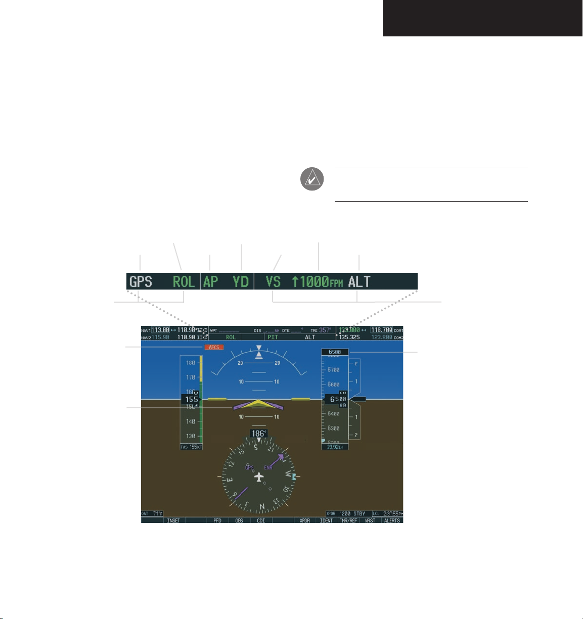
Active Mode
Armed Mode
Roll Axis Modes
System Status Field
(See Annunciations &
Alerts Pilot’s Guide)
Yaw Damper Status
Autopilot Status
Active Mode
AFCS Status Bar
Activating the Flight Director
Pressing the FD key or AP key (when FD is not active)
activates the Flight Director in default pitch/roll modes.
Pressing the GA button, or any other Fight Director mode
key activates the Flight Director in the respective mode(s).
When active, the Flight Director may be turned off by
pressing the FD key, if the Autopilot is not engaged.
NOTE: The FD key is disabled when the Autopilot
is engaged.
Mode Reference
Armed Mode
Pitch Axis Modes
Selected Altitude
Box
Flight Director
Command Bars
190-00609-00 Rev. B
Figure 9.2.1 PFD AFCS Display
Garmin G1000 AFCS Pilot’s Guide for Beechcraft A36/G36
9-5
Page 8

FD OPERATION
AFCS Status Bar
Flight Director mode annunciations are displayed on
the PFD, whenever the Flight Director is active. Figure
9.2.1 shows each individual AFCS Status Bar field. Roll
modes are displayed on the left side and pitch modes are
displayed on the right. Armed modes are displayed in
white and active modes are displayed in green. Refer to
Section 9.3 for Flight Director mode information.
Command Bars
Upon activation, the Flight Director displays command
bars on the PFD. Figure 9.2.2 shows the command bars.
The command bars move together vertically to indicate
pitch commands, and will bank left or right to indicate
roll commands. If the attitude information being sent to
the Flight Director becomes invalid or unavailable, the
command bars are removed from the display.
9-6
Figure 9.2.2 Command Bars
Flight Director Limitations
The maximum commanded pitch and roll attitudes
are limited to values established during AFCS certification. Maximum commanded pitch and roll rates are also
limited. Pitch commands are limited to 20 degrees nose
up and 15 degrees nose down. Roll commands are limited to 22 degrees of bank and a 5 degrees/second bank
rate. Limits may be different from these values in certain
modes, as noted in the section for the mode operation.
Garmin G1000 AFCS Pilot’s Guide for Beechcraft A36/G36
190-00609-00 Rev. B
Page 9
FD MODES
9.3 FLIGHT DIRECTOR MODES
Flight Director modes are normally selected independently for the pitch and roll axes. Unless otherwise speci
fied, all mode keys are alternate action (i.e. press on, press
off).
PITCH MODES
The GFC 700 AFCS offers the following pitch modes:
• Pitch Hold (default)
• Altitude Hold
• Vertical Speed
• Flight Level Change
• Glideslope
• Go Around
Table 9.3.1 equates each pitch mode to the respective
key or switch, and gives accompanying mode annuncia
tions. Mode annunciations for pitch modes are shown in
green during normal operation.
Mode
Key
{default} Pitch Hold PIT
ALT Altitude Hold ALT FT nnnnn
VS Vertical Speed VS FPM nnnn
Pitch
Mode
Annunciation
Window
-
-
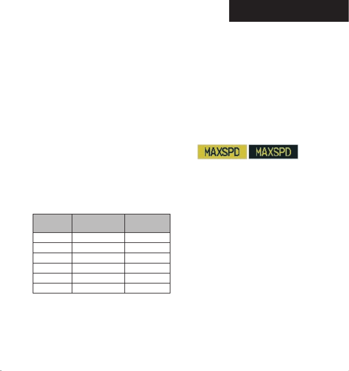
Overspeed Protection
While Vertical Speed, Flight Level Change, or default
Pitch Hold modes are selected, airspeed is monitored by
the Flight Director. In these modes, pitch commands
are limited to provide overspeed protection. Overspeed
protection occurs in situations where the Flight Director
cannot acquire and maintain the pitch mode reference for
the selected pitch mode without exceeding the certified
maximum Autopilot airspeed.
When in overspeed mode, the airspeed reference box
appears above the airspeed tape, flashing alternatively between the annunciations depicted in the figure below:
Figure 9.3.1 Overspeed Annunciations
When an Autopilot overspeed warning occurs, the pilot should reduce engine power and/or adjust the pitch
reference to slow the aircraft. When the overspeed condition is resolved, the annunciation disappears and the
previous pitch mode resumes control.
GO AROUND Go Around GA
190-00609-00 Rev. B
FLC Flight Level Change FLC KT nnn
APR Glideslope GS
Table 9.3.1 Pitch Modes
Garmin G1000 AFCS Pilot’s Guide for Beechcraft A36/G36
9-7
Page 10
FD MODES
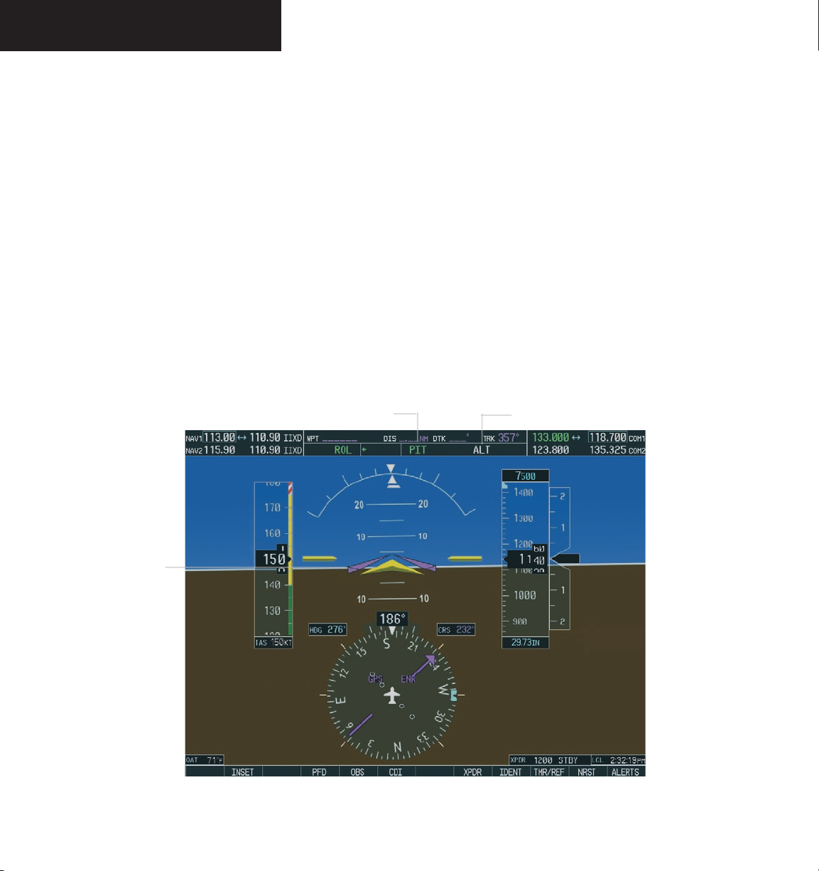
Pitch Hold Mode (PIT)
When the Flight Director is activated (the FD key is
pressed), Pitch Hold is selected by default. Pitch Hold
mode is indicated by the annunciation ‘PIT’ appearing in
the active pitch mode field in green. In Pitch Hold mode,
the Flight Director maintains a constant pitch attitude,
known as a pitch reference. The pitch reference conforms
to the aircraft attitude at the moment of engagement.
Pitch Hold mode is active
Changing the Pitch Reference
When operating in Pitch Hold mode, the pilot can ad
just the pitch reference using the NOSE UP/NOSE DN
keys in 0.5-degree increments. Flight Director pitch reference can also be changed by pressing the CWS button,
hand-flying the aircraft to establish a new pitch reference,
then releasing the CWS button.
Altitude Hold mode is armed
9-8
Flight Director
command bars
maintain desired
pitch reference
Figure 9.3.2 Pitch Hold Mode
Garmin G1000 AFCS Pilot’s Guide for Beechcraft A36/G36
190-00609-00 Rev. B
Page 11

FD MODES
Altitude Hold Mode (ALT)
The Altitude Hold mode is engaged by pressing the
ALT key. In this mode, the Flight Director establishes the
current aircraft altitude as the altitude reference.
Changing the Altitude Reference
If desired, the pilot can press the
hand-fly the aircraft to a new altitude reference. When
the CWS button is released at the desired altitude, the
new altitude is established as the altitude reference.
NOTE: If the Selected Altitude is captured during
CWS maneuvering, the Flight Director altitude
reference is not changed. To adjust the altitude
reference in this case, the pilot must again press
the CWS button after the Selected Altitude is
captured.
Altitude Hold Mode is active
CWS button and
Altitude Arm/Capture
Altitude Hold mode is armed automatically when the
Flight Director is in Pitch Hold, Vertical Speed, Flight
Level Change, and Go Around modes. This is indicated
by the annunciation ‘ALT’, shown in white to the right of
the active pitch mode as shown in Figure 9.3.3. When
armed, the Flight Director captures and levels off at the
Selected Altitude. When the Flight Director starts the al
titude capture, it transitions to the Altitude Hold mode
and holds Selected Altitude. The white ‘ALT’ annunciation moves to the active pitch mode field and flashes green
for ten seconds, indicating to the pilot the transition to
Altitude Hold mode.
Altitude Reference
Selected Altitude
Flight Director
command bars
hold pitch attitude
to maintain the
altitude reference
190-00609-00 Rev. B
Figure 9.3.3 Altitude Hold Mode
Garmin G1000 AFCS Pilot’s Guide for Beechcraft A36/G36
Selected Altitude Bug
9-9
Page 12

FD MODES
Vertical Speed Mode (VS)
The Vertical Speed mode is activated by pressing the
VS key. The annunciation ‘VS’ appears in the active pitch
mode field, along with the vertical speed reference on the
right. A separate vertical speed reference box appears directly above or below the Vertical Speed tape depending
on the whether the aircraft is climbing or descending. A
vertical speed reference bug is displayed on the tape as
well.
In Vertical Speed mode, the Flight Director acquires
and maintains the vertical speed reference established
by the pilot. Current aircraft vertical speed becomes the
vertical speed reference at the moment of Vertical Speed
mode engagement.
Vertical Speed Reference
Vertical Speed Mode is active
Flight Director
command bars
indicating a climb
at the prescribed
vertical speed,
to the Selected
Altitude
Changing the Vertical Speed Reference
The vertical speed reference is changed in 100-fpm in
crements by using the NOSE UP/NOSE DN keys. Pilots
may also press the CWS button and hand-fly the aircraft
to attain a new vertical speed. Upon releasing the CWS
button, the new vertical speed reference is established.
NOTE: The vertical speed reference is limited to
between +1500 and –3000 fpm.
Altitude Hold Mode is Armed.
Selected Altitude
Vertical Speed
Reference Box
Vertical Speed
Reference Bug
9-10
Figure 9.3.4 Vertical Speed Hold Mode
Garmin G1000 AFCS Pilot’s Guide for Beechcraft A36/G36
190-00609-00 Rev. B
Page 13

FD MODES
Flight Level Change Mode (FLC)
The Flight Level Change mode is selected by pressing the FLC key. This mode acquires and maintains the
airspeed reference. The airspeed reference is displayed
directly above the airspeed tape and in the pitch reference
field to the left of the ‘FLC’ annunciation. The airspeed
reference is set to current aircraft airspeed when engaged.
NOTE: The Selected Altitude should be set before
engaging Flight Level Change mode.
Flight Level Change Mode is active
Airspeed Reference
Box
Flight Level Change mode maintains the airspeed reference while climbing or descending to the Selected Altitude. The pilot must adjust the engine power to allow the
Autopilot to fly the aircraft at a pitch attitude which corresponds to the airspeed reference and the desired flight
profile (descent or climb). The Flight Director maintains
current altitude until either engine power or the airspeed
reference are adjusted and does not allow the aircraft to
climb or descend away from the Selected Altitude.
Changing the Airspeed Reference
The airspeed reference may be adjusted in 1-knot
increments between 80 and 190 knots, using the
NOSE UP/NOSE DN keys. The pilot may also press the
CWS button, hand-fly the aircraft to a new airspeed, then
release the CWS button.
Airspeed Reference
Altitude Hold Mode is armed
Airspeed Reference
Bug
190-00609-00 Rev. B
Figure 9.3.5 Flight Level Change Mode
Garmin G1000 AFCS Pilot’s Guide for Beechcraft A36/G36
9-11
Page 14

FD MODES
Glideslope Mode (GS)
Glideslope mode is only available when the Flight
Director is operating in the Approach mode. Glideslope
mode is automatically armed under the following conditions:
• A valid localizer frequency is tuned
• The LOC mode is selected on the HSI, with valid
deviation indicator
• The APR key is pressed
Figure 9.3.6 Glideslope Mode Armed
NOTE: Pressing the CWS button while the
Glideslope mode is active does not cancel the
mode. The Autopilot guides the aircraft back to
the glideslope upon releasing the CWS button.
Upon reaching the glideslope, the Flight Director transitions to Glideslope mode and begins to intercept and
track the glideslope.
Approach Mode active, Autopilot engaged
Active ILS
frequency is tuned
Flight Director
command bars
indicating descent
on localizer/
glideslope path
LOC1 is the
active navigation
receiver on the
HSI
Glideslope Mode is active
Figure 9.3.7 Approach Mode
9-12
Garmin G1000 AFCS Pilot’s Guide for Beechcraft A36/G36
190-00609-00 Rev. B
Page 15

Go Around Mode (GA)
Pressing the GA button engages the Flight Director in a
wings level, 7-degree pitch-up attitude. Go Around mode
disengages the Autopilot, and cancels all armed modes including Altitude Hold. Other roll modes may be selected
after Go Around mode engagement. Subsequent Autopilot engagement is also allowed. An attempt to modify
the pitch attitude (e.g with the CWS button or the NOSE
UP/NOSE DN keys) results in the Flight Director reverting to Pitch Hold mode.
Autopilot disconnect annunciation
Go Around Mode is
active for the Roll and
Pitch axis modes
flashes yellow for 5 seconds
FD MODES
Flight Director
command bars
indicating climb
190-00609-00 Rev. B
Figure 9.3.8 Go Around Mode
Garmin G1000 AFCS Pilot’s Guide for Beechcraft A36/G36
9-13
Page 16

FD MODES
ROLL MODES
Wings Level/Roll Hold Mode (ROL)
The GFC 700 offers the following roll modes:
sence of a specific roll mode (i.e., the FD key is pressed),
• Roll Hold
Roll Hold mode is active under the following conditions:
• Heading Select
• Navigation
• Approach
• Go Around
The table below equates each roll mode to the respec
-
tive key and gives accompanying mode annunciations.
Key Function
Annunciation
Window
{default} Roll Default ROL
HDG Heading Select HDG
VOR Enroute
Arm/Capture/Track
VOR
Changing the Roll Reference
GPS Arm/Capture/Track GPS
NAV
APR
BC Arm/Capture/Track BC
LOC Arm/Capture/Track;
(No Glideslope)
GPS Arm/Capture/Track
VOR Approach
Arm/Capture/Track
LOC
GPS
VAPP
ILS Approach
Arm/Capture/Track
(Glideslope Pitch Mode
LOC
pressing the
angle, then releasing the CWS button. The selection of
Wings Level or Roll Hold is the same as for mode engagement.
automatically armed)
GA Go Around (Wings Level) GA
Whenever the Flight Director is activated in the ab-
• If the aircraft bank angle is
greater than or equal to
6 degrees, Roll Hold mode is selected by default.
The Flight Director maintains the roll attitude of
the aircraft at the moment of selection.
• If the aircraft bank angle is less than 6 degrees,
Wings Level is selected by default, and the Flight
Director rolls the wings level.
Both modes are annunciated by ‘ROL’.
Figure 9.3.9 Roll Hold Mode
The pilot can establish a new reference to hold by
CWS button, establishing the desired bank
9-14
Table 9.3.2 Roll Modes
Garmin G1000 AFCS Pilot’s Guide for Beechcraft A36/G36
190-00609-00 Rev. B
Page 17

Heading Select Mode (HDG)
The Heading Select mode acquires and maintains the
Selected Heading shown on the PFD. The Selected Heading is adjusted by using the HDG knob on the PFD or
MFD. Adjustment is shown by a heading bug on the HSI
and by the Selected Heading box.
Turns are commanded in the same direction as the bug
movement, even if the bug is turned more than 180 degrees from the present heading (e.g. a 270-degree turn to
the right). However, heading bug changes of more than
340 degrees at a time result in a turn reversal.
FD MODES
NOTE: Pressing the CWS button and hand-flying
the aircraft does not change the Selected Heading. The Autopilot guides the aircraft back to
the Selected Heading upon releasing the CWS
button.
Flight Director
command bars
tracking Selected
Heading
Selected Heading
Box
Heading Select Mode
Altitude Hold Mode is active
Selected Heading
Bug
Figure 9.3.10 Heading Select Mode
190-00609-00 Rev. B
Garmin G1000 AFCS Pilot’s Guide for Beechcraft A36/G36
9-15
Page 18

FD MODES
Navigation Mode (GPS, VOR, LOC, or BC)
The Navigation mode acquires and tracks the selected
navigation receiver on the HSI (e.g. GPS, VOR or LOC).
The Flight Director follows GPS roll steering commands
when the HSI is in GPS mode, and creates roll steering
commands from the Selected Course and deviation when
the HSI is in VOR, LOC, or BC modes. The Selected
Course is controlled using the CRS knob.
Note that the selected navigation receiver must have
a valid signal (VOR, LOC) or active GPS course (GPS) in
order for the Flight Director to enter Navigation mode.
The Navigation mode can be used to fly non-precision
GPS and LOC approaches where glideslope tracking is not
required. It also automatically selects Backcourse mode
when the localizer front course is greater than 105 degrees
from the aircraft heading.
NOTE: When making a backcourse approach, set
Selected Course to the localizer front course.
Navigation/Approach Mode Armed
If the course deviation indicator is greater than 1 dot
when the Navigation or Approach modes are selected,
the mode is automatically armed. The armed annuncia
tion appears in white to the left of the active roll mode as
shown in Figure 9.3.11.
Navigation/Approach mode (GPS selected on HSI) is armed
Figure 9.3.11 Approach Mode Armed
Navigation Mode is active, using GPS source
Flight Director
command bars
indicating a left
turn to track
GPS course and a
climb to intercept
Selected Altitude
Flight Level Change Mode is active, Altitude Hold is armed
Selected Course
GPS is active
navigation receiver
on the HSI
Figure 9.3.12 Navigation Mode
9-16
Garmin G1000 AFCS Pilot’s Guide for Beechcraft A36/G36
190-00609-00 Rev. B
Page 19

Approach Mode (GPS, VAPP or LOC)
The Approach mode acquires and tracks the selected
navigation receiver on the HSI (GPS, VOR or LOC). This
mode uses the selected navigation receiver deviation and
desired course inputs to fly the approach. The Approach
mode provides greater sensitivity for VOR tracking than
Navigation mode, and allows the Autopilot to fly an ILS
approach with a glideslope.
NOTE: The Glideslope mode is automatically
armed when LOC mode is selected.
FD MODES
NOTE: Pressing the CWS button and hand-flying
the aircraft does not change the Selected Course
while in Navigation or Approach modes. The
Autopilot guides the aircraft back to the Selected
Course (or GPS Flight Plan) when the CWS button
is released.
Flight Director
command bars
indicating descent
on localizer/
glideslope path
LOC2 is the
active navigation
receiver on the
HSI
Approach Mode is active
Glideslope Mode is active
Figure 9.3.13 Approach Mode
190-00609-00 Rev. B
Garmin G1000 AFCS Pilot’s Guide for Beechcraft A36/G36
9-17
Page 20

FD MODES
9-18
This page intentionally left blank
Garmin G1000 AFCS Pilot’s Guide for Beechcraft A36/G36
190-00609-00 Rev. B
Page 21

AUTOPILOT
9.4 AUTOPILOT AND YAW DAMPER OPERATION
OVERVIEW
The Autopilot controls the aircraft pitch and roll attitudes, while following commands received from the Flight
Director. Pitch autotrim provides trim commands to the
pitch trim servo, to relieve any sustained effort required
by the pitch servo. The Yaw Damper reduces Dutch roll
tendencies and coordinates turns.
Autopilot Engagement
When the AP key is pressed, the system engages (activates) the Autopilot and the Yaw Damper, if they are not
already engaged. If the Flight Director is not already active, it is also activated when the AP key is pressed, and
starts in default pitch and roll modes.
Autopilot engagement is displayed in the center of the
AFCS mode annunciator field. Autopilot engagement is
indicated by a green ‘AP’ and is accompanied by a green
‘YD’ to indicate Yaw Damper operation unless the Yaw
Damper has been disengaged.
Autopilot Disengagement
Automatic Disengagement
Automatic disengagement typically occurs due to a
system failure. Automatic disengagement is indicated by
a flashing red ‘AP’ annunciation and by the Autopilot dis
connect aural alert, which continue until acknowledged.
To acknowledge the disconnect, the pilot can press the AP
DISC button or the MET ARM switch.
For the Yaw Damper, automatic disengagement will
occur when the Autopilot disengagement is caused by a
failure in a parameter that also affects the Yaw Damper.
This means that the Yaw Damper can remain operational
in some cases where the Autopilot will automatically disengage. The Yaw Damper will also disengage upon a localized failure in the Yaw Damper system.
Automatic Disconnect
Figure 9.4.2 Automatic Disconnect Annunciation
-
190-00609-00 Rev. B
Autopilot Engaged
Figure 9.4.1 Autopilot Engaged Annunciation
Garmin G1000 AFCS Pilot’s Guide for Beechcraft A36/G36
9-19
Page 22

AUTOPILOT
Manual Disengagement
The Autopilot may also be manually disengaged
by pressing the AP DISC button, the
GA button, the
MET ARM switch, or the AP key on the MFD. Manual
disengagement is indicated by a five-second flashing yellow ‘AP’ annunciation and by a two-second Autopilot disconnect aural alert. The AP DISC button or MET ARM
switch may be used to cancel the aural alert (the aural
alert only lasts 2 seconds).
Manual Disconnect
Figure 9.4.3 Manual Disconnect Annunciation
NOTE: Autopilot engagement/disengagement
is not the same as servo engagement/disengagement. Servos can be disengaged while the
Autopilot remains engaged (active) through the
use of the CWS switch.
Control Wheel Steering
For most scenarios, releasing the CWS button reengages the Autopilot with a new reference. Refer to the
Flight Director Modes section for exact CWS behavior for
each mode.
Yaw Damper
When the YD key is pressed, the system toggles the en-
gagement of the Yaw Damper. Yaw Damper engagement is
indicated by a green ‘YD’ in the center of the AFCS mode
annunciator field. Pressing the AP DISC button will also
disengage the Yaw Damper.
9-20
During Autopilot operations, the pilot may wish to
hand-fly the aircraft without disengaging the Autopilot.
Pressing and holding the CWS button disengages the servos from the flight control surfaces and allows the pilot
to hand-fly the aircraft. At the same time, the Flight Director is synchronized to the aircraft attitude during the
maneuver. The ‘AP’ annunciation is temporarily replaced
by ‘CWS’ in white for the duration of CWS activity.
Control Wheel Steering
Figure 9.4.4 CWS Annunciation
Garmin G1000 AFCS Pilot’s Guide for Beechcraft A36/G36
190-00609-00 Rev. B
Page 23

AUTOPILOT
FLIGHT CONTROL
Emergency Control Override
The GSM 85 servo mounts are equipped with slipclutches that are preset to certain values. This allows the
servos to be overridden in case of an emergency.
NOTE: Refer to the approved AFMS for specific
instructions regarding emergency procedures.
Flight Director - Autopilot Interface
The Flight Director function provides pitch and roll
commands to the GSA 81 servos, based upon the currently active Flight Director modes.
Pitch Axis
The pitch axis of the Autopilot uses pitch attitude rate
to stabilize the aircraft pitch attitude during aircraft up
sets or Flight Director maneuvers. The Flight Director
pitch commands are rate, acceleration, and attitude limited, summed with pitch rate, then sent to the pitch servo
motor.
-
Roll Axis
The roll axis of the Autopilot uses roll attitude rate to
stabilize the aircraft roll attitude during upsets or Flight
Director maneuvers. The Flight Director roll commands
are rate, acceleration, and attitude limited, summed with
roll rate, and sent to the roll servo motor.
Yaw Axis
The Yaw Damper uses yaw rate and roll attitude to
damp the natural Dutch roll response. It also uses lateral
acceleration to provide turn coordination. Yaw Damper
operation is independent of Autopilot engagement.
Pitch Trim
The pitch servo measures the output effort (torque)
and provides this signal to the pitch trim servo. The pitch
trim servo commands the motor to reduce the average
pitch servo effort.
When the Autopilot is not engaged, the pitch trim
servo may be used to provide a Manual Electric Pitch
Trim function. This allows the pilot to operate trim from
a control-wheel switch in lieu of manually operating the
trim wheel. Trim speeds are scheduled with airspeed to
provide more consistent response.
190-00609-00 Rev. B
Garmin G1000 AFCS Pilot’s Guide for Beechcraft A36/G36
9-21
Page 24

AUTOPILOT
9-22
This page intentionally left blank
Garmin G1000 AFCS Pilot’s Guide for Beechcraft A36/G36
190-00609-00 Rev. B
Page 25
9.5 PROCEDURES
0
3
6
9
12
1
5
1
8
2
1
2
4
27
3
0
3
3
0
3
6
9
1
2
1
5
1
8
21
2
4
2
7
3
0
3
3
0
7
0
P
an
oc
h
e
�
V
OR
T
AC
(
P
XN)
KFAT
KRHV
V
2
3
0
C
l
o
v
is�
VOR
T
A
C
(
CZQ)
V
1
0
7
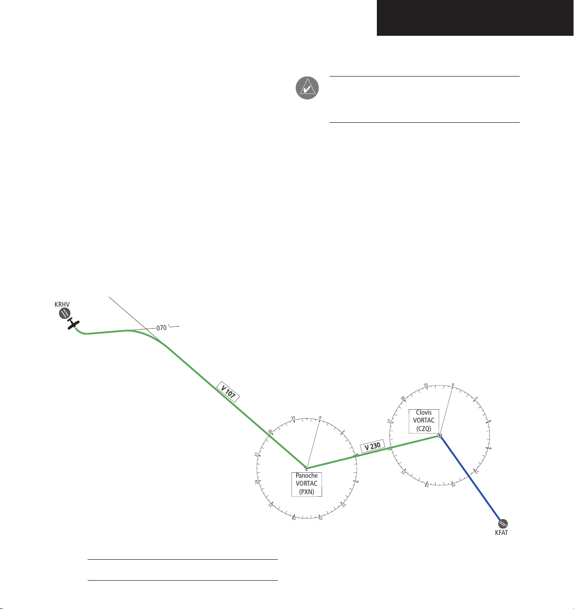
PROCEDURES
This section provides a scenario-based set of procedures showing various GFC 700 modes used during a
flight. In this scenario, the aircraft departs Reid-Hillview
Airport (KRHV) from runway 13L, en route to Fresno
Yosemite International Airport (KFAT). The pilot desires
to climb to an altitude of 7,000 feet MSL and fly heading of 070 degrees to intercept airway V107. The pilot
flies airway V107 to Panoche VORTAC (PXN) using VOR
navigation, then flies airway V230 using a GPS flight plan.
On this leg, the pilot descends to 3,000 feet prior to reaching Clovis VORTAC (CZQ) and loads the ILS approach to
R29R at KFAT. The pilot then flies the ILS approach and
executes a missed approach. Figure 9.5.1 depicts a map
of the flight plan.
NOTE: The diagrams in the following examples
are for instructional purposes only and may not
be current.
190-00609-00 Rev. B
Figure 9.5.1 Flight Plan Overview
Garmin G1000 AFCS Pilot’s Guide for Beechcraft A36/G36
9-23
Page 26

PROCEDURES
1.
2.
3.
4.
H
D
G
M
o
de
07
0
VS
M
o
d
e
,
A
L
T
M
o
d
e
A
rm
ed
ALT Mode
Selected Altitude of 7,000 MSL
5.
Departure
To Climb to Selected Altitude and Fly an
Assigned Heading:
1. Upon takeoff, the pilot sets the Selected Alti
tude to 7,000 feet, using the
the Autopilot capture this altitude, the pilot
may select from Pitch Hold, Vertical Speed, or
Flight Level Change. In this example, Vertical
Speed is used.
2. Upon reaching the desired vertical speed
of 1,000 fpm, the pilot presses the
enabling the Flight Director in Vertical Speed
mode. Altitude Hold is armed automatically.
After activating Vertical Speed mode, the pilot
presses the AP key, engaging the Autopilot in
default roll (ROL) and Vertical Speed modes.
ALT
knob. To have
VS
key,
3. With the Autopilot engaged in a climb, the pilot
sets the Selected Heading to 070 degrees using
the
HDG
knob, then presses the
HDG
Autopilot follows the heading bug on the HSI
-
and turns the aircraft to the desired heading.
4. As the aircraft climbs to the Selected Altitude,
the Flight Director changes from Vertical
Speed mode to Altitude Hold mode. This is
annunciated by the green ‘ALT’ annunciation
flashing for ten seconds, informing the pilot of
the new mode.
5. Upon reaching the Selected Altitude, the
Autopilot completes the capture process and
levels the aircraft. From this point, the Flight
Director continues to operate in Altitude Hold
mode.
key. The
9-24
Figure 9.5.2 Departure
Garmin G1000 AFCS Pilot’s Guide for Beechcraft A36/G36
190-00609-00 Rev. B
Page 27

Intercepting a VOR
1.
2.
3.
29
6
0
3
6
9
12
1
5
1
8
2
1
2
4
2
7
3
0
33
H
D
G M
o
d
e,VOR
A
rmed
07
0
VOR Mo
d
e
V
1
07
P
an
o
c
he
�
V
OR
T
AC
�
(PX
N
)
After climbout, the Autopilot continues to fly the aircraft
on a heading of 070 degrees at an altitude of 7,000 feet.
The pilot now wishes to intercept airway V107 to Panoche
VORTAC (PXN).
To Intercept a VOR:
1. The pilot tunes the VOR frequency, then sets
CDI
the HSI mode to VOR, using the
Selected Course is then set to 116 degrees
CRS
using the
knob. Note that at this point,
the Flight Director is still in Heading mode and
the Autopilot continues to fly 070 degrees.
NAV
The pilot presses the
key. This arms the
Navigation mode and the white annunciation
‘VOR’ appears to the left of the active pitch
mode.
softkey.
PROCEDURES
2. At a predetermined point, the Flight Director
changes from Heading mode to Navigation
mode, and the green annunciation ‘VOR’
flashes. The Autopilot begins turning to intercept the Selected Course.
3. The Autopilot continues the turn until the
aircraft is established on the Selected Course.
NOTE: Changing the HSI mode cancels the
Navigation mode and causes the Flight Director
to revert back to the default roll (ROL) mode.
190-00609-00 Rev. B
Figure 9.5.3 Intercepting a VOR
Garmin G1000 AFCS Pilot’s Guide for Beechcraft A36/G36
9-25
Page 28

PROCEDURES
0
3
6
9
1
2
1
5
1
8
2
1
2
4
27
3
0
3
3
1.
2.
3.
VOR
M
od
e
G
P
S
F
l
i
g
h
t P
l
a
n
L
e
g
GPS
M
od
e
0
3
6
9
12
1
5
1
8
21
2
4
2
7
3
0
3
3
V
2
3
0
Clovis�
VORTAC
(CZQ)
Panoche�
VORTAC
(PXN)
Flying a Flight Plan/GPS Course
As the aircraft closes upon Panoche VORTAC, the pilot
chooses to enter and fly a GPS flight plan for the next leg,
airway V230. To do this, the pilot enters PXN, CZQ, and
KFAT into the active flight plan.
To fly a GPS Flight Plan:
1. The aircraft is currently tracking inbound on
the 116 degree radial of Panoche VORTAC.
The pilot enters Panoche VORTAC (PXN) and
Covis VORTAC (CZQ) into the GPS flight plan,
in preparation to intercept this leg.
2. With the flight plan entered, the pilot presses
the
CDI
softkey until the HSI is in GPS mode.
Doing this cancels VOR mode on the HSI, and
the Flight Director loses the VOR signal. As a
result, the VOR annunciation flashes yellow and
the Flight Director reverts to default roll (ROL)
mode.
Flashes for five seconds, then transitions to ROL
The pilot must then press the
NAV
key to reactivate the Flight Director roll mode to use GPS
guidance. At this moment, the Flight Director
couples to GPS guidance and the Autopilot
steers the aircraft toward the active flight plan
leg.
3. Once the flight plan leg is intercepted, the
Autopilot continues to track GPS guidance to
the end of the flight plan.
9-26
Figure 9.5.4 Transition to GPS Flight
Garmin G1000 AFCS Pilot’s Guide for Beechcraft A36/G36
190-00609-00 Rev. B
Page 29

PROCEDURES
1.
2.
3.
Cruise Altitude of 7,000 MSL
Selected Altitude of 3,000 MSL
ALT Hold Mode
F
L
C
M
o
d
e
Flight Level Change Descent
While flying the GPS leg from Panoche VORTAC to
Clovis VORTAC, the pilot chooses to make a Flight Level
Change descent to 3,000 feet in preparation for the approach to KFAT.
To make a Flight Level Change descent:
1. The pilot sets the Selected Altitude to 3,000 feet
ALT
using the
FLC
key. This activates the Flight Level Change
mode. The annunciation ‘FLC’ appears along
with the airspeed reference, which defaults
to the current aircraft airspeed. Altitude Hold
mode is also armed automatically. The pilot
chooses to descend at the current cruise speed
of 142 knots.
2. To allow the Flight Level Change mode to
descend, the pilot reduces power. The Autopilot
maintains 142 knots.
knob. Then the pilot pushes the
3. At the predetermined point, the Flight Director changes from Flight Level Change mode
to Altitude Hold mode. The annunciation
‘ALT’ flashes in green, informing the pilot of
the capture. After the capture is finished, the
Autopilot holds the aircraft level at the Selected
Altitude.
190-00609-00 Rev. B
Garmin G1000 AFCS Pilot’s Guide for Beechcraft A36/G36
Figure 9.5.5 FLC Descent
9-27
Page 30

PROCEDURES
0
3
6
6
9
9
12
12
2
1
15
5
1
18
8
21
21
2
3
3
2.
3
.
HDG Mode
e
122
LOC/G
S
Mode
C
lovi
s
VORTA
C
(
CZQ
)
11
0
29
0
0
7
5
0
25
APPROACHES
ILS Approach
To fly an ILS Approach:
1. The pilot loads the Runway 29R ILS approach
for KFAT into the Flight Plan. The Pilot selects
‘Vectors to Final’ for the transition. Upon
being given vectors from ATC, the pilot sets
the Selected Heading and presses the
The Autopilot turns the aircraft to the desired
heading.
HDG
key.
2. The pilot uses the Heading mode to comply
with ATC vectors, as requested.
3. In preparation for the approach and at the
pilot’s discretion, the pilot tunes the localizer
frequency, then selects the LOC mode on the
HSI.
4. When cleared for the approach, the pilot arms
APR
the Approach mode by pressing the
key.
LOC and GS appear in the roll and pitch armed
field, respectively. The Autopilot and Flight
Director determine when to begin the turn to
intercept the final approach course.
9-28
Figure 9.5.6 ILS Approach to KFAT
Garmin G1000 AFCS Pilot’s Guide for Beechcraft A36/G36
190-00609-00 Rev. B
Page 31

PROCEDURES
0
3
6
9
12
15
18
21
24
27
30
3
3
3.
GA Mode
4.
HDG Mode
GPS Mode
CZQ
127
5. From this point, the Autopilot flies the ILS. At
the Decision Height, the pilot can press the
AP DISC
button and land the aircraft, or press
the GA button to execute a missed approach.
Go-Around/Missed Approach
To fly a Missed Approach:
1. At the Decision Height, the pilot decides to
execute a missed approach. The pilot applies
climb power and presses the
Flight Director command bars establish a 7degree nose-up climb for the pilot to follow.
Note that when the GA button is pressed, the
Autopilot disconnects and the AP annunciation
flashes yellow for five seconds.
2. Following the published Missed Approach
Procedure, the pilot climbs to the prescribed
altitude. The pilot presses the
engaging the Autopilot. To have the Autopilot
fly to the hold, the pilot sets the HSI to GPS
mode and presses the
flies direct to Clovis VORTAC according to the
loaded approach.
3. During the climb, the pilot sets a Selected
Altitude at which to hold using the
To climb to the holding altitude, the pilot may
use the
Go Around pitch mode. Doing this causes the
Flight Director to revert to the default Pitch
CWS
Hold (PIT) mode where Altitude Hold is armed.
The pilot may then choose another pitch mode
to continue with the climb, if desired.
GA
button. The
AP
key, re-
NAV
key. The Autopilot
ALT
knob.
button momentarily to cancel the
4. At the holding pattern, the pilot commences
with the hold. To fly the hold using the Auto
pilot, the pilot sets Selected Heading using the
HDG
knob and presses the
HDG
key. The
HDG
knob is used for the remainder of the hold to
guide the aircraft.
Figure 9.5.7 Go Around/Missed Approach
-
190-00609-00 Rev. B
Garmin G1000 AFCS Pilot’s Guide for Beechcraft A36/G36
9-29
Page 32

Garmin International, Inc.
1200 East 151st Street
Olathe, KS 66062, U.S.A.
p: 913.397.8200 f: 913.397.8282
Garmin AT, Inc.
2345 Turner Road SE
Salem, OR 97302, U.S.A.
p: 503.391.3411 f: 503.364.2138
Garmin (Europe) Ltd.
Unit 5, The Quadrangle
Abbey Park Industrial Estate
Romsey, SO51 9DL, U.K.
p: 44/0870.8501241 f: 44/0870.8501251
Garmin Corporation
No. 68, Jangshu 2nd Road
Shijr, Taipei County, Taiwan
p: 886/2.2642.9199 f: 886/2.2642.9099
www.garmin.com
190-00609-00 Rev. B© 2005 Garmin Ltd. or its subsidiaries
 Loading...