

Page 1

TM
G1000
VHF NAV/COM pilot’s guide
for Mooney M20M & M20R
Page 2

Record of Revisions
Revision Date of Revision Revision Page Range Description
A 5/5/05 4-1 – 4-21 Initial release.
190-00445-01 Rev. AGarmin G1000 VHF NAV/COM Pilot’s Guide for Mooney M20M & M20R
Page 3
INTRODUCTION
4.1 VHF NAV/COM
OVERVIEW
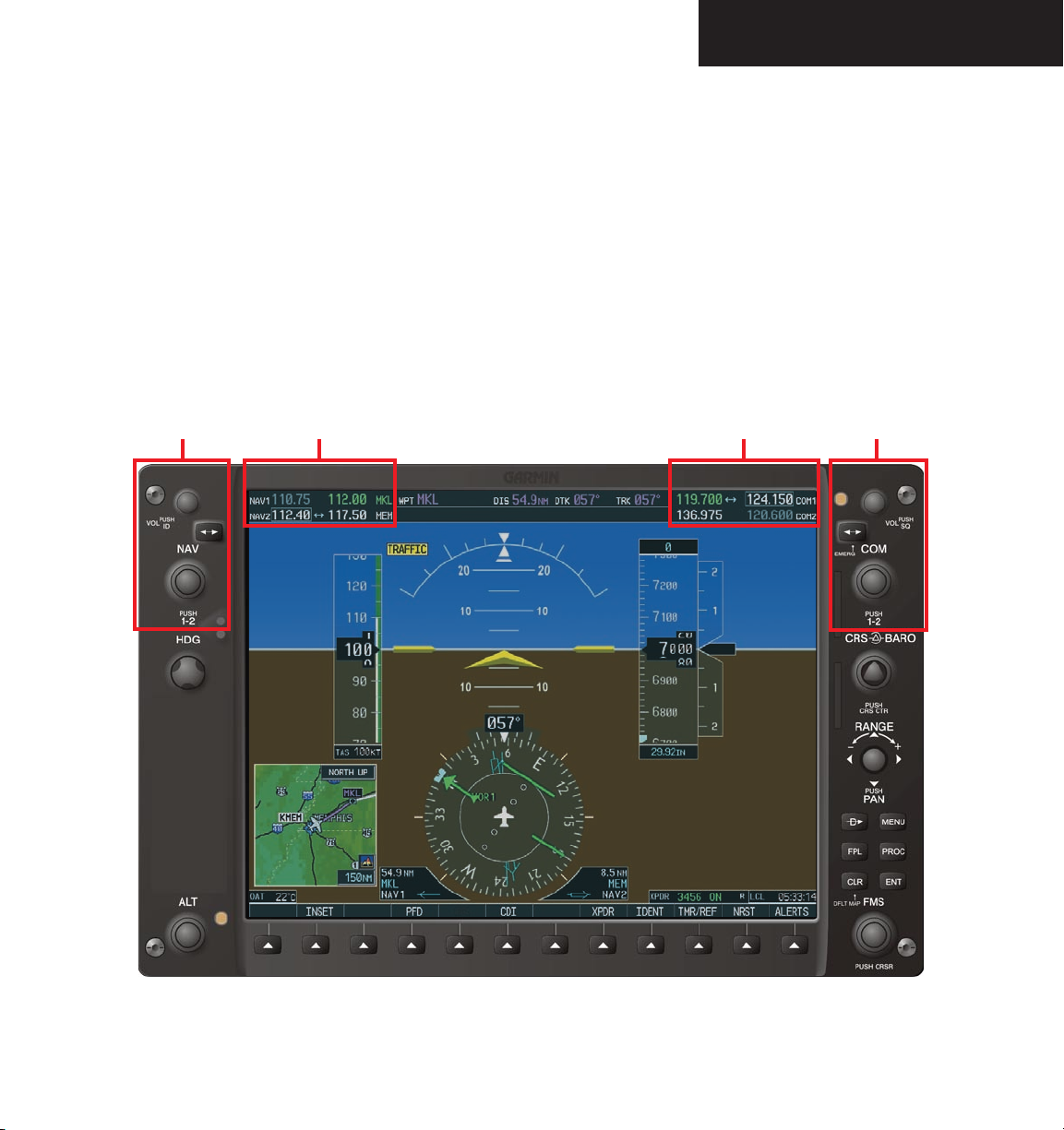
The G1000 VHF NAV/COM frequency controls and
windows are located in the top corners of the Primary
Flight Display (PFD) and Multi Function Display (MFD).
The NAV controls, windows and fields are located on the
left side. The COM controls, windows and fields are on
the right, as shown in the figure below.
NAV
Controls
NAV Frequency Window COM Frequency Window
The G1000 VHF NAV/COM interface includes:
• Windows and fields
• Radio selection
• Tuning box
• Frequency Transfer Arrow
• Radio status indications
• Controls
COM
Controls
Figure 4.1.1 G1000 VHF NAV/COM Interface (PFD)
Garmin G1000 VHF NAV/COM Pilot’s Guide for Mooney M20M & M20R190-00445-01 Rev. A
4-1
Page 4
INTRODUCTION
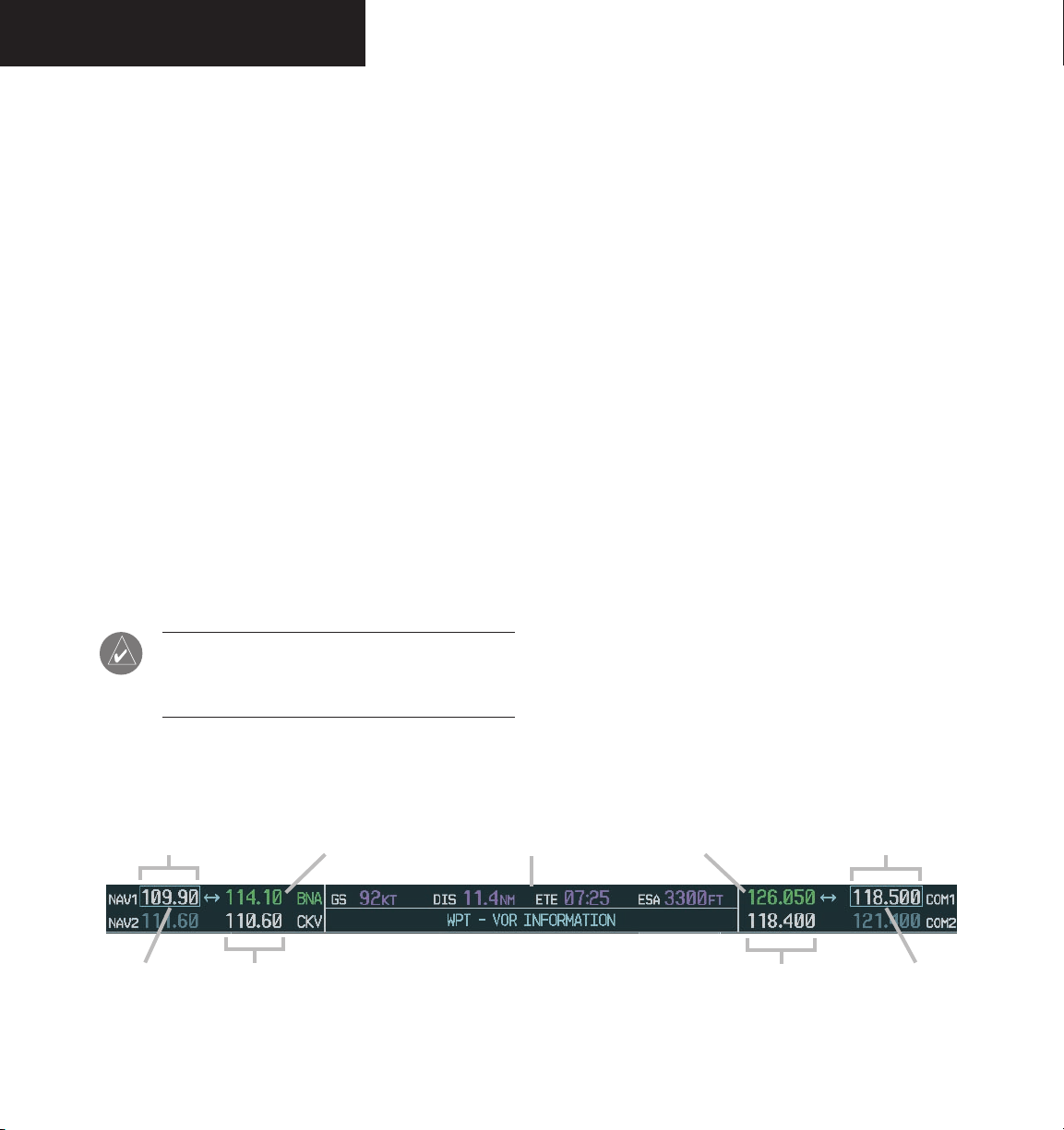
WINDOWS AND FIELDS
The NAV and COM Frequency windows are located
at the top of the display on either side of the Navigation
Status bar on both the PFD and the MFD.
• The NAV Frequency window is displayed to the left
of the Navigation Status bar.
• The
Each radio frequency window is composed of two
fields, a
• In the NAV Frequency window, the active frequency
• In the COM Frequency window, the active frequency
COM Frequency window is displayed to the
right of the Navigation Status bar.
standby field and an active field.
is on the right side, the standby frequency is on the
left.
is on the left side, the standby frequency is on the
right.
NOTE: In GPS mode, both active NAV frequencies are displayed in white indicating they are
not active.
RADIO SELECTION
The NAV radio is selected with the CDI softkey lo-
cated on the PFD.
• When NAV1 radio is selected, a single green arrow
labeled either ‘VOR1’ or ‘LOC1’ is displayed on the
HSI.
• When NAV2 radio is selected, a double green arrow
labeled either ‘VOR2’ or ‘LOC2’ is displayed on the
HSI.
The active COM radio is selected with the audio panel COM1 MIC or COM2 MIC keys. COM1 MIC key
activates the COM1 transceiver. COM2 MIC key activates COM2.
Frequencies located in the active field are displayed
in either green or white.
• An active frequency displayed in green indicates that
the radio is selected on the audio panel (COM) or
HSI (NAV).
• An active frequency displayed in white indicates that
the radio is not selected on the audio panel (COM)
or the HSI (NAV).
Standby NAV
Frequency Field
Tuning Box
Selected NAV
Active NAV
Frequency Field
Garmin G1000 VHF NAV/COM Pilot’s Guide for Mooney M20M & M20R 190-00445-01 Rev. A4-2
Radio
Navigation Status Bar
Figure 4.1.2 Frequency Fields
Selected COM
Radio
Frequency Field
Active COM
Standby COM
Frequency Field
Tuning Box
Page 5
INTRODUCTION
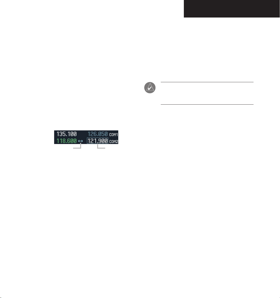
TUNING BOX
A light blue tuning box appears around the standby
frequency field on both the PFD and MFD. It can be
moved from one standby frequency field to another for
tuning or radio selection by pressing the dual COM or
NAV knob.
Frequencies located in the
in either white or gray.
• The standby frequency appearing in the tuning box
is white.
• The standby frequency that is not in the tuning box
is gray.
Frequency Transfer Arrow
Figure 4.1.3 Frequency Transfer Arrow and Tuning Box
standby field are displayed
Tuning Box
FREQUENCY TRANSFER ARROW
A Frequency Transfer Arrow appears between active
and standby frequencies in both the COM and NAV windows. Pressing the Frequency Transfer
standby and active frequencies. Pressing the dual
key toggles the
COM
or NAV knob transfers both the frequency tuning box and
the Frequency Transfer Arrow between the radios.
NOTE: When a signal is received or transmitted,
the Frequency Transfer Arrow is replaced by a
white RX or TX indication.
RADIO INDICATORS
• RX – When a COM signal is received, a white RX
appears by the active COM frequency during signal
reception.
• TX – When a COM radio is keyed, a white TX
appears by the active COM frequency during transmission.
• ID – When the Morse code identifier is ON for a
NAV radio, a white ID appears to the left of the active
NAV frequency. The Morse code identifier is heard
when a NAV radio is selected on the audio panel.
Garmin G1000 VHF NAV/COM Pilot’s Guide for Mooney M20M & M20R190-00445-01 Rev. A
4-3
Page 6
INTRODUCTION
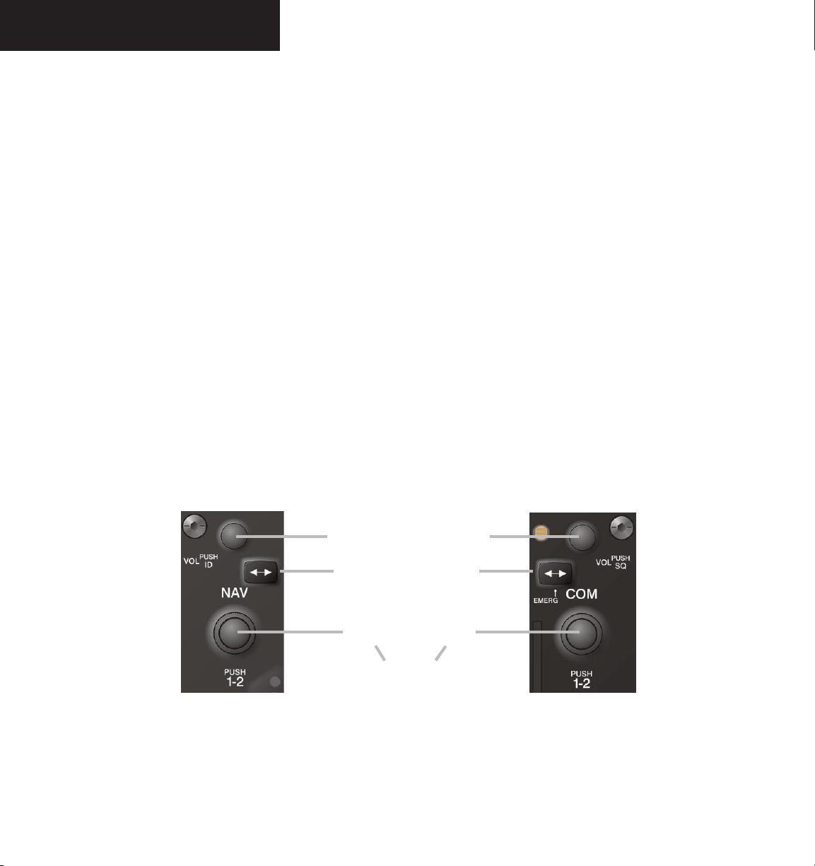
CONTROLS
The NAV Frequency window is controlled by knobs
and keys on the left, the COM Frequency window by
knobs and keys on the right.
The NAV controls:
• VOL/PUSH ID knob
– Turn to adjust the NAV radio volume level.
– Press to turn the Morse code ID ON and OFF.
• Frequency Transfer key
– Press to transfer the NAV frequencies between
the active and standby fields.
• Dual
NAV tuning knob
– Turn to tune a NAV frequency in the NAV
tuning box (
large knob for MHz; small knob
for kHz).
– Press to transfer the NAV tuning box between
the NAV1 and NAV2 radios.
The COM controls:
• VOL/PUSH SQ knob
– Turn to adjust the COM radio volume.
– Press to turn automatic squelch ON and OFF.
• Frequency Transfer key
– Press to transfer the COM frequencies between
the active and standby fields.
– Press and hold for two seconds to tune the
emergency frequency (121.500 MHz) in the
active COM field.
• Dual
COM tuning knob
– Turn to tune a COM frequency in the COM
tuning box (large knob for MHz; small knob
for kHz).
– Press to transfer the COM tuning box between
the COM1 and COM2 radios.
NAV Controls COM Controls
VOL/PUSH
ID Knob
Frequency Transfer Keys
Dual NAV
Knob
• Turn to tune desired
frequencies.
• Press to change tuning box
positions.
Figure 4.1.4 NAV/COM Controls
Garmin G1000 VHF NAV/COM Pilot’s Guide for Mooney M20M & M20R 190-00445-01 Rev. A4-4
VOL/PUSH
SQ Knob
Dual COM
Knob
Page 7
OPERATION – COM
4.2 COM OPERATION
FREQUENCY SPACING
The G1000 COM radios can tune either 25 kHz spacing (118.000 to 136.975 MHz) or 8.33 kHz spacing
(118.000 to 136.990 MHz) frequencies.
COM channel spacing is configured through the MFD
on the System Setup Page of the AUX Page group.
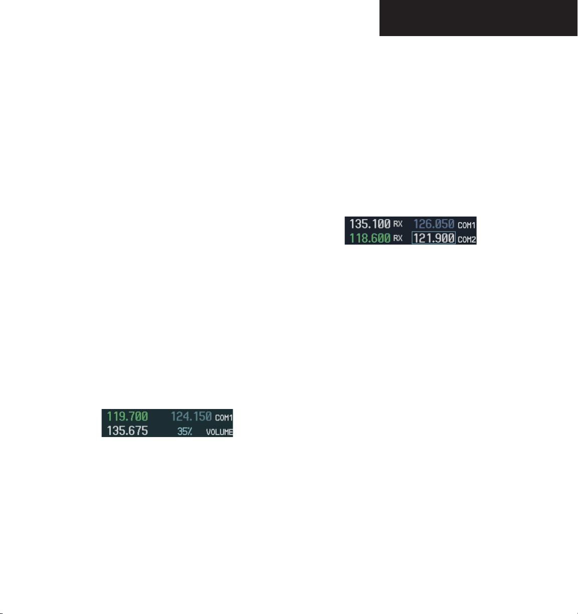
VOLUME
COM radio volume level can be adjusted from 0 to
100% in increments of 3.25%, using the VOL/PUSH SQ
knob located above the COM Frequency Transfer key.
Turning the VOL/PUSH SQ knob clockwise increases
volume, turning the knob counterclockwise decreases
volume.
When adjusting volume level for a COM radio, volume
level is displayed in place of the standby COM frequency.
The COM1 or COM2 annunciator is replaced by the word
VOLUME. Volume level remains in the COM Frequency
window for two seconds after the change.
AUTOMATIC SQUELCH
Automatic squelch provides maximum sensitivity to
weaker signals while canceling most localized noise sources. Automatic squelch can be disabled for a COM radio
by pressing the COM knob to select the desired COM
sub-window, then by pressing the VOL/PUSH SQ knob.
When automatic squelch is disabled,
mains continuously open and an RX indication appears
while continuous noise is heard over the speaker and
phones.
Figure 4.2.2 Overriding Automatic Squelch
To return to automatic squelch, press the VOL/PUSH
SQ knob again.
COM audio re-
Figure 4.2.1 COM Volume Level
Garmin G1000 VHF NAV/COM Pilot’s Guide for Mooney M20M & M20R190-00445-01 Rev. A
4-5
Page 8
OPERATION – COM
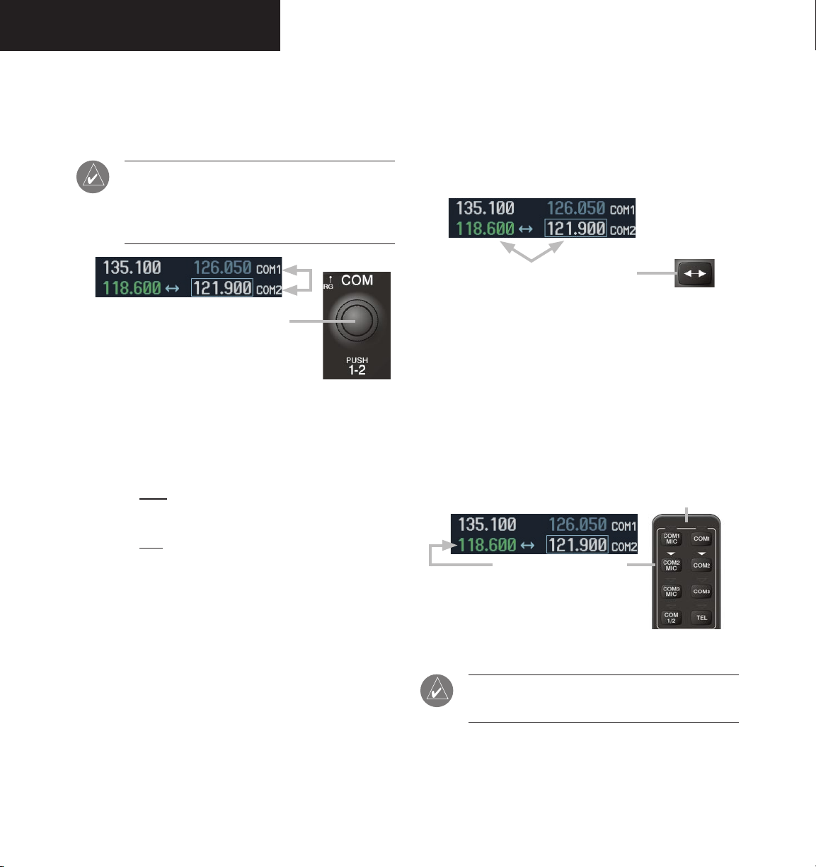
SWITCHING BETWEEN COM RADIOS
Pressing the dual COM knob transfers the frequency
tuning box between the COM1 and COM2 fields.
NOTE: When a different transceiver (COM MIC
key) is selected on the audio panel, the frequency
tuning box also transfers on both the PFD and
MFD.
Pushing the dual COM knob switches the
tuning box from one COM radio to the other.
Figure 4.2.3 Switching COM Radios
MANUALLY TUNING A COM FREQUENCY
COM frequency manual tuning is done with the dual
COM knob. The frequency is tuned in the standby field.
• The
MHz frequency digits are tuned with the large
COM knob.
TOGGLING COM FREQUENCIES
Pressing the COM Frequency Transfer key toggles
the COM frequencies between the active and standby
fields of the COM radio having the Frequency Transfer
Arrow.
Pressing the COM Frequency Transfer
key toggles the COM frequencies.
Figure 4.2.4 Transfering COM Frequencies
SELECTING A COM RADIO
The desired COM radio is selected using the COM
MIC keys on the audio panel. When the COM MIC key
is annunciated, the associated active COM frequency is
displayed in green in the COM Frequency window.
Top section of the
audio panel
4-6
• The
kHz frequency digits are tuned with the small
COM knob.
Turning the knobs clockwise increases frequency.
Turning the knobs counterclockwise decreases frequency.
Garmin G1000 VHF NAV/COM Pilot’s Guide for Mooney M20M & M20R 190-00445-01 Rev. A
The COM radio is selected
on the audio panel.
Figure 4.2.5 Selecting a COM Radio
NOTE: Refer to the Audio Panel Pilot’s Guide for
more details on transceiver selection.
Page 9

OPERATION – COM
RADIO STATUS
When a COM radio is keyed, a white TX indication appears to the right of the active COM frequency to indicate
transmission.
When a COM signal is received, a white
appears to the right of the active COM frequency to indi
RX indication
-
cate signal reception.
Figure 4.2.6 Radio Status Indications
NOTE: When transmitting or receiving, the
Frequency Transfer Arrow disappears and is
replaced by a white TX or RX indication.
EMERGENCY FREQUENCY (121.500 MHZ)
In case of a COM system tuning failure, the emergency
frequency (121.500 MHz) is automatically loaded in the
active frequency field of the radio in which the tuning failure was detected.
Quick-Tuning and Activating 121.500 MHz
Pressing and holding the COM Frequency Transfer
key for two seconds automatically loads the emergency
COM frequency (121.500 MHz) in the active field of the
active COM radio (the one with the transfer arrow).
Figure 4.2.8 Quickly Tuning 121.500 MHz
STUCK MICROPHONE
If the COM1 or COM2 push-to-talk (PTT) switch becomes stuck, the COM transmitter times out after 35 seconds of continuous transmitting. An alert appears on the
PFD to advise the crew of a stuck microphone.
Figure 4.2.9 Stuck Microphone Alert
Figure 4.2.7 COM Tuning Failure
NOTE: In case of a dual display failure, the emer-
gency frequency (121.500 MHz) is automatically
placed in the active field of the active COM
radio.
Garmin G1000 VHF NAV/COM Pilot’s Guide for Mooney M20M & M20R190-00445-01 Rev. A
4-7
Page 10

OPERATION – COM
This page intentionally left blank.
4-8
Garmin G1000 VHF NAV/COM Pilot’s Guide for Mooney M20M & M20R 190-00445-01 Rev. A
Page 11

OPERATION – NAV
4.3 NAV OPERATION
FREQUENCY RANGE
The G1000 NAV radios receive in the VOR/ILS frequency range of 108.00 to 117.95 MHz with 50 kHz
spacing. The Nav Frequency window displays the following information:
• NAV1 and NAV2 active and standby frequencies
• NAV1 and NAV2 identifier indication (if the Morse
code identifier is received by the system).
• Color-coded indication of the selected NAV radio
• Morse code identifier status
VOLUME
NAV radio volume level can be adjusted from 0 to
100% in increments of 3.25%, using the VOL/PUSH ID
knob. Turning the VOL/PUSH ID knob clockwise increases volume, turning the knob counterclockwise decreases volume. When adjusting the volume for a NAV
radio, volume level is displayed in place of the standby
NAV frequency. Volume level remains in the NAV Frequency window for two seconds after the change.
MORSE CODE IDENTIFIER
Pressing the VOL/PUSH ID knob toggles the Morse
code identifier ON and OFF. When the Morse code identifier is ON, a white ID indication appears to the left of the
active NAV frequency. When the Morse code identifier is
OFF, the ID indication disappears and the Morse code is
filtered out of the NAV audio.
The Morse code identifier is ON for the
The Morse code ID for an active NAV channel is heard
when the white ID is displayed and the NAV radio is selected on the audio panel. Nav audio is available with the
ID filtered out for listening to HIWAS and FSS transmissions on VOR stations.
NAV2 is the NAV radio
selected on the audio panel.
The Morse code identifier for
the GHM VOR can be heard.
GHM VOR.
Figure 4.3.2 ID Indication
NAV section
of the audio
panel
Figure 4.3.1 NAV Volume Level
Garmin G1000 VHF NAV/COM Pilot’s Guide for Mooney M20M & M20R190-00445-01 Rev. A
Figure 4.3.3 Morse Code Identifier Audio
NOTE: When a VOR signal is received, the VOR/
LOC Morse code identifier is displayed to the right
of the active NAV frequency.
4-9
Page 12

OPERATION – NAV
SWITCHING BETWEEN NAV RADIOS
Pressing the dual NAV knob transfers the frequency
tuning box between the NAV1 and NAV2 radios.
Pushing the dual NAV knob switches the tuning
box from one NAV radio to the other.
Figure 4.3.4 Switching NAV Radios
NOTE: When a different NAV radio is selected
on the HSI, the NAV frequency tuning box also
changes on the PFD and MFD. However, the NAV
frequency tuning box does not change when GPS
mode is selected.
MANUALLY TUNING A NAV FREQUENCY
NAV frequency manual tuning is done with the dual
NAV knob.
TOGGLING NAV FREQUENCIES
Pressing the NAV Frequency Transfer key toggles the
NAV frequencies between the active and standby fields of
the NAV radio having the Frequency Transfer Arrow.
Pressing the NAV Frequency Transfer
key toggles the NAV frequencies.
Figure 4.3.5 Toggling NAV Frequencies
4-10
• The
MHz frequency digits are tuned with the large
NAV knob.
• The
kHz frequency digits are tuned with the small
knob.
NAV
The frequency is tuned in the standby field. Turning
the knobs clockwise increases frequency. Turning the
knobs counterclockwise decreases frequency.
Garmin G1000 VHF NAV/COM Pilot’s Guide for Mooney M20M & M20R 190-00445-01 Rev. A
Page 13

SELECTING A NAV RADIO
The desired NAV radio is selected using the CDI softkey located on the PFD. The three navigation modes that
can be selected are:
• VOR1 (or LOC1) – If NAV1 is selected, a single
green arrow (shown) labeled either ‘VOR1’ or
‘LOC1’ is displayed on the HSI and the active NAV1
frequency is displayed in green.
OPERATION – NAV
• VOR2 (or LOC2) – If NAV2 is selected, a double
green arrow (not shown) labeled either ‘VOR2’ or
‘LOC2’ is displayed on the HSI and the active NAV2
frequency is displayed in green.
• GPS – If GPS mode is selected, a single magenta
arrow (not shown) appears on the HSI and neither
NAV radio is selected.
NOTE: In GPS mode, both active NAV frequencies
are displayed in white.
The NAV radio is
selected by the CDI
softkey.
Figure 4.3.6 Selecting a NAV Radio
Garmin G1000 VHF NAV/COM Pilot’s Guide for Mooney M20M & M20R190-00445-01 Rev. A
4-11
Page 14

OPERATION – NAV
This page intentionally left blank.
4-12
Garmin G1000 VHF NAV/COM Pilot’s Guide for Mooney M20M & M20R 190-00445-01 Rev. A
Page 15

OPERATION – AUTO-TUNING
4.4 FREQUENCY AUTO-TUNING
The G1000 system offers multiple auto-tuning capabilities. The PFD allows auto-tuning of COM frequencies
associated with the nearest airports. The MFD provides
auto-tuning of both COM and NAV frequencies from waypoint and nearest pages. In addition, the primary NAV
frequency is entered automatically in the NAV window
during yapproach loading or approach activation.
Frequencies can be automatically loaded into the fre
quency windows in the following ways:
• By using the
ENT key when the frequency is high-
lighted on the appropriate page (PFD and MFD).
• When loading or activating an approach (PFD and
MFD).
NOTE: Turn the FMS knob to scroll through a
list of frequencies.
Press the ENT key to load
a highlighted frequency
into the frequency window.
-
AUTO-TUNING ON THE PFD
COM frequencies for the nearest airports may be
viewed and automatically loaded from the Nearest Airports window on the PFD.
To auto-tune a COM frequency for a nearby
airport:
NRST
1. Press the
Airports window, which displays the list of
airport identifiers and COM frequencies.
2. Turn either
COM frequency.
3. Press the
into the COM tuning box.
NOTE: When the desired frequency is entered in
the tuning box, it becomes a standby frequency.
Pressing Frequency Transfer places this fre-
quency into the active field.
softkey to open the Nearest
FMS
knob to highlight the desired
ENT
key to load the COM frequency
Turn the
FMS knob
to scroll through a
list of frequencies.
Figure 4.4.1 Loading Frequencies
Pressing the
the Nearest Airports window
Garmin G1000 VHF NAV/COM Pilot’s Guide for Mooney M20M & M20R190-00445-01 Rev. A
NRST softkey opens
Figure 4.4.2 Nearest Airports Window (PFD)
4-13
Page 16

OPERATION – AUTO-TUNING
AUTO-TUNING ON THE MFD
Frequencies can be selected and loaded from the fol-
lowing MFD pages:
• WPT – Airport Information
• WPT – VOR Information
• NRST – Nearest Airports
• NRST – Nearest VOR
• NRST – Nearest Frequencies
Figure 4.4.3 MFD Page Group Icon
NOTE: In NAV mode during any VOR/ILS
approach activation, the NAV frequency is automatically loaded into the standby field of the
selected NAV radio.
NOTE: In GPS mode during any VOR/ILS approach
activation, the appropriate NAV frequency is
automatically loaded into the active field of
NAV1.
WPT – Information Page
The Airport Information Page displays runway information and a list of frequencies for the selected airport
identifier as well as departure, arrival and approach information.
To display the entire list of frequencies for
an airport:
1. On the Airport Information Page, press the
INFO
softkey to display runway and frequency
information for a specific airport.
FMS
2. Press the
cursor in the window.
3. Turn the
identifier and press the
available frequencies for the selected airport
appears.
knob to activate the selection
FMS
knob to select the desired airport
ENT
key. A list of all
4-14
Figure 4.4.4 WPT – Airport Information Page (INFO)
Garmin G1000 VHF NAV/COM Pilot’s Guide for Mooney M20M & M20R 190-00445-01 Rev. A
Page 17

OPERATION – AUTO-TUNING
To load a COM frequency into the COM tuning
box:
1. When the list of frequencies for the selected
airport is displayed, highlight the desired fre
quency by turning the
ENT
2. Press the
NOTE: The runway Pilot Controlled Lighting
(PCL) frequency (located in the Runways box of
the INFO portion of the Airport Information Page)
may also be highlighted with the large FMS knob
and loaded into the COM tuning box by pressing
the ENT key.
key.
large FMS
knob.
To load the primary approach NAV frequency
into the NAV tuning box:
APR
1 On the Airport Information Page, press the
-
softkey to display approach information for a
specific airport.
FMS
2. Press the
knob to activate the selection
cursor in the window.
3. Turn the
large FMS
knob to highlight the
primary NAV frequency located in the Primary
Frequency box.
ENT
4. Press the
key.
Figure 4.4.5 WPT – Airport Information Page (APR)
Garmin G1000 VHF NAV/COM Pilot’s Guide for Mooney M20M & M20R190-00445-01 Rev. A
4-15
Page 18

OPERATION – AUTO-TUNING
WPT – VOR Information Page
The VOR Information Page displays information specific to individual VORs, including the airport that is nearest to the VOR.
To load a VOR frequency into the NAV
window:
1. On the VOR Information Page, press the
FMS
knob to activate the VOR Information
window.
FMS
2. Turn the
desired VOR and press the
the selection.
knob as needed to select the
ENT
key to validate
NOTE: If the MENU key is pressed when on the
VOR Information Page, the ‘View Recent VOR
List’ menu option is displayed for quick access to
recently used VORs. If no VOR frequencies have
been tuned, this menu option is grayed out.
3. Turn the
large FMS
frequency and press the
knob to highlight the VOR
ENT
key to load this
frequency into the tuning box of the NAV
Frequency window.
4-16
Figure 4.4.6 WPT – VOR Information Page
Garmin G1000 VHF NAV/COM Pilot’s Guide for Mooney M20M & M20R 190-00445-01 Rev. A
Page 19

NRST – Nearest Airports Page
The Nearest Airports Page displays a list of the nearest
airports as well as related runway, frequency and approach
information. On this page, any frequency associated with
the selected airport can be loaded into the NAV or COM
Frequency window.
To display the entire list of frequencies for
a nearby airport and load a frequency from
that list:
1. On the Nearest Airports Page, press the
knob to activate the selection cursor in the
Nearest Airports window.
FMS
2. Turn the
knob to scroll through the list
of nearest airport identifiers until the desired
nearest airport is highlighted.
FREQ
3. Press the
softkey to activate the selection
cursor in the Frequencies box.
FMS
OPERATION – AUTO-TUNING
FMS
4. Turn the
knob to scroll through the list of
frequencies for the selected airport.
5. When the desired frequency is highlighted,
ENT
press the
key to load this frequency into
the tuning box of the appropriate Frequency
window (NAV or COM).
Garmin G1000 VHF NAV/COM Pilot’s Guide for Mooney M20M & M20R190-00445-01 Rev. A
Figure 4.4.7 NRST – Nearest Airport Page
4-17
Page 20

OPERATION – AUTO-TUNING
NRST – Nearest VOR Page
The Nearest VOR Page displays a list of the nearest
VORs together with related information, including the
VOR frequency.
To load a VOR frequency into the NAV
window:
1. On the Nearest VOR Page, press the
to activate the Nearest VOR window.
FMS
2. Turn the
of nearest VORs until the desired VOR is highlighted.
3. Press the
cursor in the Frequency box and press the
key to load the frequency into the tuning box
of the NAV Frequency window.
knob to scroll through the list
FREQ
softkey to activate the selection
FMS
knob
ENT
Figure 4.4.8 NRST – Nearest VOR Page
4-18
Garmin G1000 VHF NAV/COM Pilot’s Guide for Mooney M20M & M20R 190-00445-01 Rev. A
Page 21

OPERATION – AUTO-TUNING
NRST – Nearest Frequencies Page
The Nearest Frequencies Page displays a list of nearest
ARTCC, FSS and WX frequencies. For frequency selection, the cursor can be activated on the ARTCC, FSS, or
WX windows by using the ARTCC, FSS and WX softkeys.
To view a nearest ARTCC frequency and load
it into the standby frequency field:
ARTCC
1. Press the
tion cursor in the Nearest ARTCC window.
2. Turn the
small FMS
list of ARTCC names, then the
to highlight the desired ARTCC frequency.
3. Press the
frequency into the COM tuning box.
NOTE: The Nearest ARTCC window contains a
numbered list of ARTCC names as well as bearing
and distance information from the transmitting
antenna.
softkey to activate the selec-
knob to scroll through the
large FMS
ENT
key to load the desired ARTCC
knob
To view a nearest WX frequency and load it
into the standby frequency field:
WX
1. Press the
softkey to activate the selection
cursor in the Nearest WX window.
FMS
2. Turn the
knob to highlight the desired WX
frequency.
ENT
3. Press the
key to load the desired WX fre-
quency into the tuning box.
To view a nearest FSS frequency and load it
into the standby frequency field:
FSS
1. Press the
softkey to activate the selection
cursor in the Nearest FSS window.
2. Turn the
small FMS
list of FSS names, then the
knob to scroll through the
large FMS
knob to
highlight the desired FSS frequency.
ENT
3. Press the
key to load the desired FSS
frequency into the COM or NAV tuning box.
NOTE: The Nearest FSS window contains a list
of FSS names as well as bearing and distance
information from the transmitting antenna.
Garmin G1000 VHF NAV/COM Pilot’s Guide for Mooney M20M & M20R190-00445-01 Rev. A
Figure 4.4.9 NRST – Nearest Frequencies Page
4-19
Page 22

OPERATION – AUTO-TUNING
AUTO-TUNING ON APPROACH ACTIVATION (NAV FREQUENCIES)
NAV frequencies are automatically loaded into the
NAV Frequency window on approach activation, regardless of the display unit being used.
NOTE: The primary NAV frequency becomes
auto-tuned upon loading an approach.
To auto-tune a NAV frequency if the desired
approach is not already loaded:
PROC
1. Press the
window.
key to open the Procedures
2. Turn the
large FMS
knob to highlight the
‘SELECT APPROACH’ menu option and press
the
ENT
key.
FMS
3. Use both the
knob and the
needed to select the desired airport, VOR/ILS
approach and transition.
4. Turn the
large FMS
knob to highlight either the
‘LOAD?’ or ‘ACTIVATE?’ prompt and press the
ENT
key. The primary NAV frequency for the
activated approach is loaded into the standby
field of the selected NAV radio.
ENT
Figure 4.4.10 Selecting an Approach
key as
Figure 4.4.11 Loading an Approach
4-20
Garmin G1000 VHF NAV/COM Pilot’s Guide for Mooney M20M & M20R 190-00445-01 Rev. A
Page 23

To auto-tune a NAV frequency if the desired
approach is already loaded:
PROC
1. Press the
key to open the Procedures
window.
OPERATION – AUTO-TUNING
2. Turn the
large FMS
knob to highlight the
‘ACTIVATE APPROACH’ menu option and
press the
ENT
key. The approach primary NAV
frequency becomes automatically loaded into
the standby field of the selected NAV radio.
NOTE: If the system is in GPS mode when a
VOR/ILS approach is loaded or activated, the
approach primary NAV frequency is automatically
loaded into the active field of NAV1.
NOTE: Before loading or activating an approach,
the primary NAV frequency may be loaded into
the NAV tuning box by highlighting the frequency
in the Select Approach window using the FMS
knob, then pressing the ENT key.
NOTE: The NAV frequency is also automatically
loaded upon vector-to-final activation, if the NAV
frequency is not already loaded in the selected
NAV radio.
Figure 4.4.12 Activating an Approach
NOTE: When a VOR/ILS approach has been
activated in GPS mode, and the ILS CDI Capture
option is set to AUTO, the system switches to NAV
mode as the final approach course is intercepted
(within 15 nm from the FAF). See the Multi Function Display Pilot’s Guide for details.
NOTE: An approach can also be activated with
the MENU key when the Flight Plan window is
open.
Garmin G1000 VHF NAV/COM Pilot’s Guide for Mooney M20M & M20R190-00445-01 Rev. A
4-21
Page 24

Garmin International, Inc.
1200 East 151st Street
Olathe, KS 66062, U.S.A.
p: 913.397.8200 f: 913.397.8282
Garmin AT, Inc.
2345 Turner Road SE
Salem, OR 97302, U.S.A.
p: 503.391.3411 f: 503.364.2138
Garmin (Europe) Ltd.
Unit 5, The Quadrangle
Abbey Park Industrial Estate
Romsey, SO51 9DL, U.K.
p: 44/0870.851241 f: 44/0870.851251
Garmin Corporation
No. 68, Jangshu 2nd Road
Shijr, Taipei County, Taiwan
p: 886/2.2642.9199 f: 886/2.2642.9099
www.garmin.com
190-00445-01 Rev. A © 2005 Garmin Ltd. or its subsidiaries
 Loading...