

Page 1

TM
G1000
system overview for
Mooney M20M & M20R
Page 2

Record of Revisions
Revision Date of Revision Revision Page Range Description
A 05/16/05 ------ Initial release.
Garmin G1000 System Overview for Mooney M20M & M20R 190-000442-01 Rev. A
Page 3

SYSTEM OVERVIEW
2.1 SYSTEM DESCRIPTION
This document is designed to provide an overview
of the G1000 Integrated Cockpit System as installed in
Mooney M20M & M20R aircraft.
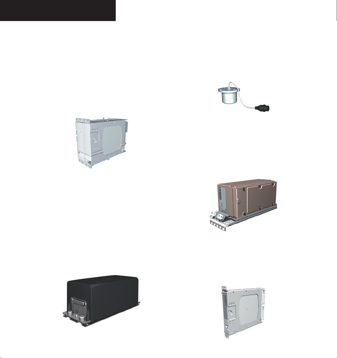
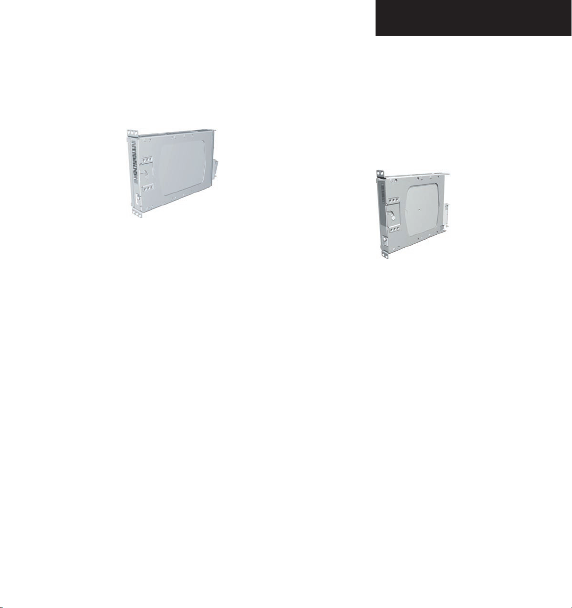
The G1000 system includes the following Line Re
placeable Units (LRUs):
• GDU 1040 Primary Flight Display (PFD)
• GDU 1040 Multi Function Display (MFD)
• GIA 63 Integrated Avionics Units (2)
• GEA 71 Engine/Airframe Unit
• GDC 74A Air Data Computer (ADC)
• GRS 77 Attitude and Heading Reference System
(AHRS)
• GMU 44 Magnetometer
• GMA 1347 Audio System with integrated Marker
Beacon Receiver
• GTX 33 Mode-S Transponder
• GDL 69/69A Data Link
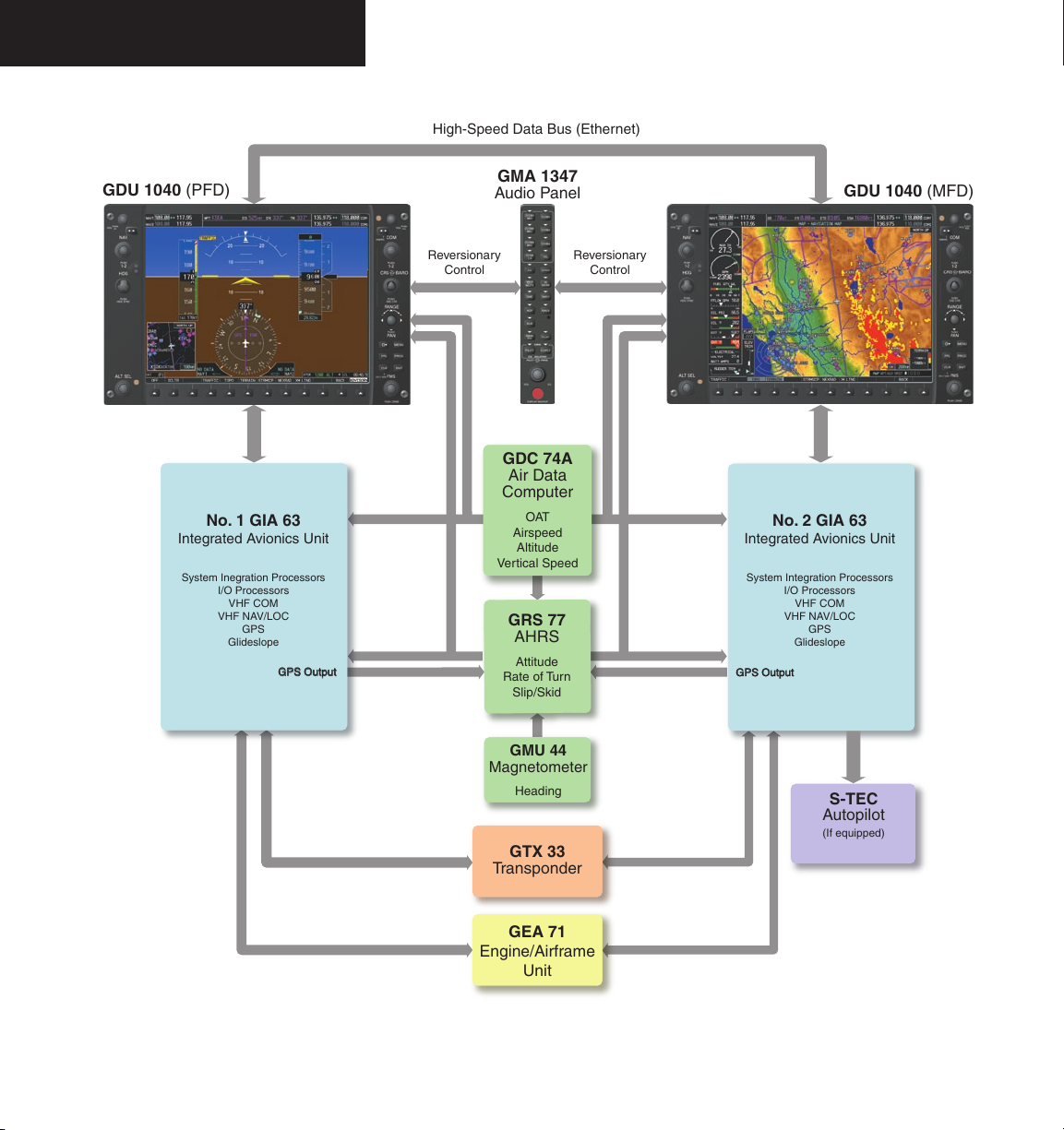
The LRUs are further described in the following sec
tion. All LRUs have a modular design, which greatly eases
troubleshooting and maintenance of the G1000 system. A
top-level G1000 block diagram is given in Figure 2.2.1.
Additional or optional interfaces are depicted in Figure
2.2.2.
NOTE: Please refer to the Pilot’s Guide
Appendices for detailed specifications regarding
the G1000 LRUs.
-
-
2.2 LINE REPLACEABLE UNITS
• GDU 1040 – The GDU 1040 features a 10.4-inch
LCD display with 1024 x 768 resolution. The left
display is configured as a PFD and the right display
is configured as an MFD. Both GDU 1040s link and
display all functions of the G1000 system during
flight. The displays communicate with each other
through a High-Speed Data Bus (HSDB) Ethernet
connection. Each display is also paired via an Ethernet connection with a GIA 63 Integrated Avionics
Unit.
• GMA 1347 – The GMA 1347 integrates NAV/COM
digital audio, intercom system and marker beacon
controls. The GMA 1347 also controls manual
display reversionary mode (red DISPLAY BACKUP
button) and is installed between the MFD and the
PFD. The GMA 1347 communicates with both
GIA 63s using an RS-232 digital interface.
190-000442-01 Rev. A Garmin G1000 System Overview for Mooney M20M & M20R
2-1
Page 4
SYSTEM OVERVIEW
• GIA 63 – The GIA 63 is the central Integrated Avionics Unit (IAU) of the G1000 system. The GIA 63
functions as a main communication hub, linking all
LRUs with the PFD and the MFD displays. Each
GIA 63 contains a GPS receiver, VHF COM/NAV/GS
receivers, and system integration microprocessors.
Each GIA 63 is paired with a respective GDU 1040
display through Ethernet. The GIAs are not paired
together and do not communicate with each other
directly.
• GRS 77 – The GRS 77 is an Attitude and Heading
Reference System (AHRS) that provides aircraft
attitude and heading information to both the
G1000 displays and the GIA 63s. The unit contains
advanced sensors, accelerometers and rate sensors.
In addition, the GRS 77 interfaces with both the
GDC 74A Air Data Computer and the GMU 44
Magnetometer. The GRS 77 also utilizes GPS signals
sent from the GIA 63. Attitude and heading information is sent using an ARINC 429 digital interface
to both GDU 1040s and GIA 63s. AHRS modes of
operation are discussed later in this document.
• GMU 44 – The GMU 44 Magnetometer measures
local magnetic field information. Data is sent to
the GRS 77 AHRS for processing to determine aircraft magnetic heading. This unit receives power
directly from the GRS 77 and communicates with
the GRS 77 using an RS-485 digital interface.
• GDC 74A – The GDC 74A Air Data Computer
processes information from the pitot/static system
as well as the outside air temperature (OAT) sensor.
The GDC 74A provides pressure altitude, airspeed,
vertical speed and OAT information to the G1000
system, and communicates with the GIA 63s,
GDU 1040s and GRS 77 using an ARINC 429 digital
interface.
• GEA 71 – The GEA 71 receives and processes signals
from the engine and airframe sensors. Sensor types
include engine temperature and pressure sensors as
well as fuel measurement and pressure sensors. The
GEA 71 communicates with both GIA 63s using an
RS-485 digital interface.
2-2
190-000442-01 Rev. AGarmin G1000 System Overview for Mooney M20M & M20R
Page 5
SYSTEM OVERVIEW
• GTX 33 – The GTX 33 is a solid-state, Mode-S
transponder that provides Modes A, C and S operation. The GTX 33 is controlled through the PFD
and communicates with both GIA 63s through an
RS-232 digital interface.
• GDL 69/69A – The GDL 69/69A is an XM satellite radio receiver that provides real-time weather
information to the G1000 MFD. The GDL 69A
also provides digital audio entertainment in the
cockpit. The GDL 69/69A communicates with the
MFD on the High-Speed Data Bus. A subscription
to the XM Satellite Radio service is required for the
GDL 69/69A to be used.
190-000442-01 Rev. A Garmin G1000 System Overview for Mooney M20M & M20R
2-3
Page 6
SYSTEM OVERVIEW
No. 1 GIA 63
Integrated Avionics Unit
System Inegration Processors
I/O Processors
VHF COM
VHF NAV/LOC
GPS
Glideslope
No. 2 GIA 63
Integrated Avionics Unit
System Integration Processors
I/O Processors
VHF COM
VHF NAV/LOC
GPS
Glideslope
GTX 33
Transponder
High-Speed Data Bus (Ethernet)
Reversionary
Control
GEA 71
Engine/Airframe
Unit
GDC 74A
Air Data
Computer
OAT
Airspeed
Altitude
Vertical Speed
GRS 77
AHRS
Attitude
Rate of Turn
Slip/Skid
GMU 44
Magnetometer
Heading
G
P
S
O
u
t
p
u
t
G
P
S
O
u
t
p
u
t
Reversionary
Control
GMA 1347
Audio Panel
GDU 1040 (PFD)
GDU 1040 (MFD)
S-TEC
Autopilot
(If equipped)
2-4
Figure 2.2.1 Basic G1000 System (Mooney)
190-000442-01 Rev. AGarmin G1000 System Overview for Mooney M20M & M20R
Page 7

SYSTEM OVERVIEW
High-Speed Data Bus (Ethernet)
No. 2 GIA 63
Integrated Avionics Unit
System Integration Processors
I/O Processors
VHF COM
VHF NAV/LOC
GPS
Glideslope
L3
Stormscope
Lightning Strike and
Thunderstorm Detection
Becker
ADF Receiver
Honeywell
KN 63
DME
GDL 69/69A
Data Link
Real-time Weather
Digital Audio Entertainment
Consult a Garmin authorized
service center for optional
equipment availability and
configuration. For information
on optional equipment described
in this manual, refer to the
Garmin Optional Equipment
Pilot's Guide.
190-000442-01 Rev. A Garmin G1000 System Overview for Mooney M20M & M20R
Figure 2.2.2 G1000 Optional Equipment
2-5
Page 8

SYSTEM OVERVIEW
This page intentionally left blank.
2-6
190-000442-01 Rev. AGarmin G1000 System Overview for Mooney M20M & M20R
Page 9

2.3 PFD/MFD CONTROLS
SYSTEM OVERVIEW
3
421 6
5
7
8
9
17
1
NAV VOL/ID Knob
2
NAV Frequency Toggle Key
3
NAV Knob
4
Heading Knob
5
Range Joystick
6
Course/Baro Knob
7
COM Knob
8
COM Frequency Toggle Key
9
COM VOL/SQ Knob
Figure 2.3.1 PFD/MFD Controls
10
Direct-to Key
11
Flight Plan Key
12
Clear Key
13
Flight Management System Knob
14
Menu Key
15
Procedure Key
16
Enter Key
17
Altitude Knob
10
11
12
13
190-000442-01 Rev. A Garmin G1000 System Overview for Mooney M20M & M20R
14
15
16
2-7
Page 10

SYSTEM OVERVIEW
The G1000 controls and keys have been designed to
simplify the operation of the system and minimize work
load as well as the time required to access sophisticated
functionality. The following list provides an overview of
the controls located on the display bezel.
• (1) NAV VOL/ID Knob – Controls the NAV audio
level. Press to toggle the Morse code identifier ON
and OFF. Volume level is shown in the field as a
percentage.
• (2) NAV Frequency Toggle Key – Toggles the
standby and active NAV frequencies.
• (3) Dual NAV Knob – Tunes the MHz (large knob)
and kHz (small knob) standby frequencies for the
NAV receiver. Press to toggle the tuning cursor (cyan
box) between the NAV1 and NAV2 fields.
• (4) Heading Knob – Manually selects a heading
when turned. Synchronizes the heading bug with
the compass lubber line when pressed.
• (5) Joystick – Changes the map range when rotated.
Activates the map pointer when pressed.
• (6) CRS/BARO Knob – The large knob sets the
altimeter barometric pressure and the
small knob
adjusts the course. The course is only adjustable
when the HSI is in VOR1, VOR2, or OBS/SUSP
mode. Pressing this knob centers the CDI on the
currently selected VOR.
• (7) Dual COM Knob – Tunes the MHz (large knob)
and kHz (small knob) standby frequencies for the
COM transceiver. Pressing this knob toggles the
tuning cursor (cyan box) between the COM1 and
COM2 fields.
• (8) COM Frequency Toggle Key – Toggles the
standby and active COM frequencies. Pressing and
holding this key for two seconds automatically tunes
the emergency frequency (121.5 MHz) in the active
frequency field.
• (9) COM VOL/SQ Knob – Controls COM audio
level. Pressing this knob turns the COM automatic
squelch ON and OFF. Audio volume level is shown
in the field as a percentage.
• (10) Direct-to Key ( ) – Allows the user to
enter a destination waypoint and establish a direct
course to the selected destination (specified by the
identifier, chosen from the active route, or taken
from the map cursor position).
• (11) FPL Key – Displays the active Flight Plan Page
for creating and editing the active flight plan, or for
accessing stored flight plans.
• (12) CLR Key (DFLT MAP) – Erases information,
cancels an entry, or removes page menus. To display
the Navigation Map Page immediately, press and hold
CLR (MFD only).
• (13) Dual FMS Knob – Used to select the page to be
viewed (only on the MFD). The large knob selects a
page group (MAP, WPT, AUX, NRST), while the small
knob selects a specific page within the page group.
Pressing the small knob turns the selection cursor
ON and OFF. When the cursor is ON, data may be
entered in the different windows using the small and
large knobs. The large knob is used to move the
cursor on the page, while the small knob is used to
select individual characters for the highlighted cursor
location. When the G1000 displays a list that is too
long for the display screen, a scroll bar appears along
the right side of the display, indicating the availability
of additional items within the selected category. Press
the FMS/PUSH CRSR knob to activate the cursor
and turn the large FMS knob to scroll through the
list.
• (14) MENU Key – Displays a context-sensitive
list of options. This list allows the user to access
additional features, or to make setting changes that
relate to certain pages.
2-8
190-000442-01 Rev. AGarmin G1000 System Overview for Mooney M20M & M20R
Page 11

SYSTEM OVERVIEW
• (15) PROC Key – Selects approaches, departures
and arrivals from the flight plan. If a flight plan is
used, available procedures for the departure and/or
arrival airport are automatically suggested. If a
flight plan is not used, the desired airport and the
desired procedure may be selected. This key selects
IFR departure procedures (DPs), arrival procedures
(STARs) and approaches (IAPs) from the database
and loads them into the active flight plan.
• (16) ENT Key – Accepts a menu selection or data
entry. This key is used to approve an operation
or complete data entry. It is also used to confirm
selections and information entries.
• (17) Dual ALT Knob – Sets the reference altitude
in the box located above the Altimeter. The large
knob selects the thousands, while the small knob
selects the hundreds.
NOTE: The selected COM (displayed in green)
is controlled by the COM MIC key on the audio
panel (GMA 1347).
2.4 SECURE DIGITAL CARDS
The GDU 1040 data card slots use Secure Digital (SD)
cards. SD cards are used for aviation database updates
and terrain database storage.
To install an SD card:
1. Insert the SD card in the SD card slot located
on the right side of the display bezel (the front
of the card should be flush with the face of the
display bezel).
To remove an SD card:
1. Gently press on the SD card to release the
spring latch and eject the card.
NOTE: Please refer to the Pilot’s Guide Appen-
dices for instructions on updating the aviation
database.
190-000442-01 Rev. A Garmin G1000 System Overview for Mooney M20M & M20R
2-9
Page 12

SYSTEM OVERVIEW
2.5 SYSTEM POWER-UP
The G1000 system is integrated with the aircraft electrical system and receives power directly from electrical
busses. The Garmin G1000 PFD/MFD and supporting
sub-systems include both power-on and continuous builtin test features that exercise the processor, RAM, ROM,
external inputs and outputs to provide safe operation.
While the system begins to initialize, test annunciations
are displayed to the pilot at power-up, as shown in the
figure below. All system annunciations should be cleared
within one (1) minute of power-up. The GMA 1347 also
annunciates all bezel lights briefly upon power-up.
NOTE: Please see the Aircraft Flight Manual
(AFM) for specific procedures concerning avionics
power application and emergency power supply
operation.
On the PFD, the AHRS system displays the ‘AHRS
ALIGN: Keep Wings Level’ message and begins to initialize. The AHRS should display valid attitude and heading
fields within one (1) minute of power-up. The AHRS can
align itself both while taxiing and during level flight.
NOTE: Please refer to the Pilot’s Guide Appendices for AHRS initialization bank angle limitations.
NOTE: See the Annunciations and Alerts Pilot’s
Guide for additional information regarding
system annunciations and alerts.
2-10
Figure 2.5.1 PFD Initialization
190-000442-01 Rev. AGarmin G1000 System Overview for Mooney M20M & M20R
Page 13

SYSTEM OVERVIEW
When the MFD powers up, the MFD Power-up Page
displays the following information:
• System version
• Copyright
• Checklist filename
• Land database name and version
• Obstacle database name and version
• Terrain database name and version
• Aviation database name, version and effective
dates
When this information has been reviewed for currency
(to ensure that no databases have expired), the pilot is
prompted to continue. Current database information is
displayed with the valid operating dates, cycle number
and database type.
Press the
ENT key to acknowledge this information
and proceed to the Navigation Map Page. When the
system has acquired a sufficient number of satellites to
determine a position, the Navigation Map Page appears,
showing the aircraft current position.
Figure 2.5.2 MFD Power-up Page
190-000442-01 Rev. A Garmin G1000 System Overview for Mooney M20M & M20R
2-11
Page 14

SYSTEM OVERVIEW
2.6 DISPLAY BACKLIGHTING
The G1000 PFD and MFD displays use photocell
technology to automatically adjust for ambient lighting
conditions. Photocell calibration curves are pre-configured to optimize display appearance through a broad
range of cockpit lighting conditions. The PFD, MFD, and
GMA 1347 bezel/key lighting is normally controlled directly by the existing instrument panel dimmer bus.
If desired, the PFD and MFD display backlighting may
be adjusted manually. The PFD, MFD and GMA 1347
bezel/key brightness can also be adjusted manually. The
GMA 1347 bezel/key brightness is directly tied to the
MFD bezel/key adjustment.
NOTE: Please refer to the Primary Flight Display
Pilot’s Guide for instructions on adjusting backlighting manually.
2.7 SYSTEM OPERATION
NORMAL MODE
The PFD and MFD are connected together on a single
Ethernet bus, allowing for high-speed communication be
tween the two units. Each GIA 63 is connected to a single
display, as shown in Figure 2.2.1. This allows the units to
share information, thus enabling true system integration.
In normal operating mode, the PFD displays graphical
flight instrumentation in lieu of the traditional gyro instruments. Attitude, heading, airspeed, altitude and verti
cal speed are all shown on one display. The MFD shows a
full-color moving map with navigation information. Both
displays offer control for COM and NAV frequency selection, as well as for the heading, course/baro and altitude
reference functions. On the left of the MFD display, the
Engine Indication System (EIS) cluster shows engine and
airframe instrumentation. Figure 2.7.1 gives an example
of the G1000 system in normal mode.
-
-
2-12
Figure 2.7.1 Normal Mode
190-000442-01 Rev. AGarmin G1000 System Overview for Mooney M20M & M20R
Page 15

REVERSIONARY MODE
Should a failure occur in either display, the G1000
automatically enters reversionary mode. In reversionary
mode, all important flight information is shown on the remaining display. An example of reversionary mode entry
due to a failed PFD is shown in Figure 2.7.2.
If a display fails, the GIA 63-GDU 1040 Ethernet inter
face is cut off. Thus, the GIA can no longer communicate
with the remaining display (refer to Figure 2.2.1), and the
NAV and COM functions provided to the failed display by
the GIA are flagged as invalid on the remaining display,
as a result. The system reverts to using backup paths for
the GRS 77, GDC 74A, GEA 71 and GTX 33, as required.
The change to backup paths is completely automated for
all LRUs, and no pilot action is required.
-
SYSTEM OVERVIEW
NOTE: The system alerts the pilot when backup
paths are utilized by the LRUs. Refer to the
Annunciations and Alerts Pilot’s Guide for further
information regarding these and other system
alerts.
Reversionary mode may also be manually activated by
the pilot if the system fails to detect a display problem.
Reversionary mode is activated manually by pressing
the red DISPLAY BACKUP button at the bottom of the
GMA 1347. Pressing this button again deactivates reversionary mode.
Figure 2.7.2 Reversionary Mode (Failed PFD)
190-000442-01 Rev. A Garmin G1000 System Overview for Mooney M20M & M20R
2-13
Page 16

SYSTEM OVERVIEW
AHRS OPERATION
In addition to using internal sensors, the GRS 77 AHRS
uses GPS information, magnetic field data and air data to
assist in attitude/heading calculations. In normal (primary) mode, the AHRS relies upon GPS and magnetic field
measurements. If either of these external measurements is
unavailable or invalid, the AHRS uses air data information
for attitude determination. Four AHRS modes of operation are available (see table below) and depend upon the
combination of available sensor inputs. Loss of air data,
GPS, or magnetometer sensor inputs is communicated to
the pilot by message advisory alerts.
GPS Input Failure
The G1000 system provides two sources of GPS information. If a single GPS receiver fails, or if the information provided from one of the GPS receivers is unreliable,
the AHRS seamlessly transitions to using the other GPS
receiver. An alert message informs the pilot of the use of
the backup GPS path. If both GPS inputs fail, the AHRS
continues to operate in reversionary ‘No GPS’ mode so
long as the air data and magnetometer inputs are available
and valid.
Air Data Input Failure
A failure of the air data input has no effect on AHRS
output while AHRS is operating in normal/primary mode.
A failure of the air data input while the AHRS is operating
in reversionary ‘No GPS’ mode results in invalid attitude
and heading information on the PFD (as indicated by red
‘X’ flags).
Magnetometer Failure
If the magnetometer input fails, the AHRS transitions
to one of the reversionary ‘No Magnetometer’ modes and
continues to output valid attitude information. However,
the heading output on the PFD does become invalid (as
indicated by a red ‘X’).
NOTE: Please refer to the Annunciations and
Alerts Pilot’s Guide for specific AHRS alert information.
NOTE: Pilots should be aware that aggressive
maneuvering in any of the three reversionary
modes listed below can degrade AHRS accuracy.
2-14
Available AHRS Functions Available Sensor Inputs
AHRS Mode
Pitch Roll Heading
GPS Input
(At least one)
GMU 44
Magnetometer
GDC 74A
Air Data Computer
Normal/Primary X X X X X X
Reversionary:
No GPS
Reversionary:
No Magnetometer
X X X - X X
X X - X - X
Reversionary:
No Magnetometer
X X - X - -
No Air Data
190-000442-01 Rev. AGarmin G1000 System Overview for Mooney M20M & M20R
Page 17

Page 18

Garmin International, Inc.
1200 East 151st Street
Olathe, KS 66062, U.S.A.
p: 913.397.8200 f: 913.397.8282
Garmin AT, Inc.
2345 Turner Road SE
Salem, OR 97302, U.S.A.
p: 503.391.3411 f: 503.364.2138
Garmin (Europe) Ltd.
Unit 5, The Quadrangle
Abbey Park Industrial Estate
Romsey, SO51 9DL, U.K.
p: 44/0870.8501241 f: 44/0870.8501251
Garmin Corporation
No. 68, Jangshu 2nd Road
Shijr, Taipei County, Taiwan
p: 886/2.2642.9199 f: 886/2.2642.9099
www.garmin.com
190-000442-01 Rev. A© 2005 Garmin Ltd. or its subsidiaries
 Loading...