


767 Pilot in Command
767
Pilot in Command
Microsoft Flight Simulator 2000 Upgrade
http://www.wilcopub.com
E-mail: info@wilcopub.com
Fax: +32 2 331.07.51
B.P. 30
1620 Drogenbos - Belgium
Flight Management Computer (FMC)
MANUAL
This manual is for information purpose and is intended to be used
With Microsoft Flight Simulator 2000 and 767 Pilot in Command (Wilco Publishing) only.
More information can be found on WILCO PUBLISHING website at http://www.wilcopub.com.
© 2000 - Wilco Publishing - Eric Ernst
© Wilco Publishing |
Page 1 of 108 |

767 Pilot in Command
FMC MANUAL TABLE OF CONTENTS
DESCRIPTION………………………………………………………………………….4
FMC Keyboard - 4
FMC PROGRAMMING……………………………………………………………….8
POS INIT Page - 9
ROUTE Page - 15
Loading Pre-programmed Route Data - 16
Manually Programming Route Data - 18
Advanced FMC Route Programming - 20
Activating a Route - 25
KJFK-KSEA Route Example - 27
PERF INIT Page - 28
TAKEOFF Page - 30
APPROACH Page - 31
FMC OPERATION…………………………………………………………………..32
Route Management - 32 LEGS Page - 33
LEGS Page Management - 34 Fly Direct to a Waypoint - 37 Direct Intercept Course - 39
PLACE/RADIAL/DISTANCE Waypoints - 41 Route Discontinuities - 42
New Waypoint addition - 43 Along Track Waypoints - 45 Removing Waypoints - 46
PLACE/RADIAL/PLACE/RADIAL Waypoints - 47 ABEAM Points - 49
ROUTE Copy - 50 LAT/LONG Waypoints - 52 LEGS Page Summary - 52
PROGRESS Pages - 53 NAV RAD Page - 55 HOLD Page - 56
DEPARTURE/ARRIVAL Page - 59
SID Selection (in the Route Programming page - 22) STAR Selection - 59
APPROACH/RUNWAY Selection - 60
© Wilco Publishing |
Page 2 of 108 |

767 Pilot in Command
VNAV OPERATION……………………………………………………………….63
VNAV Altitude Programming - 63
VNAV Speed Programming - 67 How to use VNAV on a Flight - 68
VNAV Climb - 68
VNAV Cruise - 71
VNAV Descent - 73
VNAV Summary - 76
SAVING FMC DATA……………………………………………………………77
Saving Route as a Flight Plan - 77
Saving Standard Instrument Departures (SIDs) - 79 Saving SID Departure Transition Procedures - 81 Saving Runway Specific SID Transitions - 83 Saving SID Example (Advanced) - 84
Saving SID Summary - 87
Saving Standard Instrument Arrivals (STARs) - 88 Saving STAR Transition Procedures - 90 Saving STAR (with Transitions) Example - 91 Saving STAR summary - 93
Saving Approach Procedures - 94 Saving Approach Transitions - 97
Saving Approach Procedures Summary - 99
Advanced FMC Data Programming Techniques - 100 SID Programming - 100
STAR Programming - 105
Approach Procedures Programming – 108
…
© Wilco Publishing |
Page 3 of 108 |

767 Pilot in Command
DESCRIPTION
The Flight Management Computer (FMC) provides for accurate management of all phases of flight. Flight planning, navigation and performance can be managed and controlled using the FMC. The FMC works in conjunction with the Autoflight system (AFDS) to allow complete management of lateral navigation (LNAV) and vertical navigation (VNAV). After programming the route of flight and all performance data into the FMC, the pilot can use the AFDS LNAV and VNAV functions exclusively to navigate the aircraft automatically without using manually tuned VORs and minimal use of the AFDS. When the AFDS is engaged in LNAV and/or VNAV mode, the primary instrument to control aircraft flight path becomes the FMC.
After explaining the FMC unit we will explore the functions of the FMC by demonstrating a flight from KDFW to KLGA. Along the way we will explain all of the functions found on the FMC and how to properly use them. The end of this chapter will explain how to program custom departure, arrival and approach procedures that are used frequently to program a route of flight.
FMC Keyboard
© Wilco Publishing |
Page 4 of 108 |

767 Pilot in Command
The FMC unit is called up on the panel using the FMC button located on the main panel or by using the keyboard combination <shift><6>. The keyboard displays conveniently over top of the EICAS screens so that it can be used during flight without covering up essential flight instruments or the AFDS panel.
The Control Display Unit (or CDU) CRT displays all FMC data. The data screens are controlled using the Function Keys and the Line Select Keys (LSK). When data is displayed in the CDU, it is arranged in “lines” of data that align with the left and right LSKs. These lines of data are referred to as “data blocks”. The data contained next to a LSK can usually be changed using the keyboard and LSKs. This procedure will be shown during our practice route explanation.
The Line Select Keys are arranged down the left and right sides of the CDU. There are 6 keys on each side of the CDU. For ease of explanation these keys are named as follows: The keys on the left side are referred to from top to bottom as “1L” through “6L”, the keys on the right side are referred to from top to bottom as “1R” through “6R”. For example, if a reference is made to the “3R” LSK, this means the third button from the top down the right side.
Manual entry of data into the FMC is done using the Data Entry Keys. Keypad entries are displayed in the Scratch Pad. If a mistake is made, pressing the “CLR” key will clear out each digit individually. Alternatively, pressing the “blank” key to the right of the “Z” key can clear an entire line of data. Information in the Scratch Pad can be transferred into a CDU data block by pressing the adjacent LSK. If the data is in the correct format, it is transferred into the CDU when the LSK abeam the data block is pressed. This procedure will be shown during our practice route explanation. The Scratch Pad is also used by the FMC to display special messages.
There is a hidden mouse click area on the CDU CRT screen abeam the 1L LSK. It is highlighted in the picture at right. Pressing this mouse area displays a “KA” as shown in the upper left corner of the CRT. “KA” stands for “keyboard assist”. When displayed, anything you type on your
computers keyboard will be entered into the FMC scratchpad. This eliminates the need to press the Data Entry Keys using mouse clicks. Please note that when the KA feature is being used, all keyboard assignments for panel functions are temporarily deactivated. To restore keyboard assignments to the panel functions, deactivate the KA feature by clicking the hidden mouse click area so that “KA” is no longer displayed on the CRT.
© Wilco Publishing |
Page 5 of 108 |

767 Pilot in Command
The Function Keys are used to display data screens and access functions that are used most often by the pilot during flight. When a function key is pressed, the CDU displays the data for that function which can then be managed by the pilot. Each screen will be described during our practice route explanation. Here is a quick summary of the operable function keys (note the ATC, FMC COMM, and FIX buttons are not functioning at this time):
INIT REF: Initialization and Reference page. When pressed, displays performance and/or reference pages. The page displayed when this key is pressed is dependent on the current phase of flight. All INIT REF pages have an “< INDEX” prompt next to the 6L LSK. Pressing the 6L LSK displays the INIT REF index page. From this index page, selection of all INIT REF pages is possible.
RTE: Route page. When pressed, displays the ROUTE page. This page is used to enter all route information. This page permits entry of all waypoints for your route as well as Jet and Victor airways that are converted by the FMC into waypoints.
DEP ARR: Departure and Arrival pages. When pressed, displays the departure and arrival procedure pages. From this page you can select SIDs, STARs, and approach procedures for the departure and destination airport. If the database has the information for that airport, you can select the desired procedure that is then entered into the route in the proper sequence.
VNAV: Vertical navigation pages. When pressed, displays the pages required for proper VNAV operation. From these pages, automatic control of aircraft speed and altitude is possible.
LEGS: Legs pages. When pressed, displays the LEGS page that lists all waypoints in the current route. This page is used to make route modifications. The route created by the waypoints listed in the LEGS page is followed by LNAV when properly engaged on the AFDS. All LEGS are listed on the EHSI and are connected using a pink course line. The pink course line is the track followed during AFDS LNAV mode operation.
HOLD: Hold page. When pressed, displays the HOLD function or the HOLD pages. This feature allows the pilot to create a holding pattern at any waypoint listed in the active LEGS page.
PROG: Progress pages. When pressed, displays the PROGRESS pages that list data related to the progress of the flight.
EXEC: Execute key. This key lights up any time there has been a modification to FMC data that requires “execution” to become active. Prior to pressing the EXEC key, the FMC modifications are not activated and the FMC continues to
© Wilco Publishing |
Page 6 of 108 |

767 Pilot in Command
use the old data. Once EXEC is pressed, the FMC modifications become active and the FMC uses the freshly input data.
MENU: Menu key. When pressed, displays a MENU screen that has a prompt used when saving FMC LEGS data.
NAV RAD: Navigation Radio page. When pressed, displays information about the currently tuned navigation radios.
PREV/NEXT PAGE: When pressed, cycles through pages on the CDU. In the upper right corner of most CDU screens there is a page counter (x/x). If there is more than one page of data available, the other pages can be viewed using these keys. For example, if “1/3” is displayed in the upper right corner of the CDU, this means that page 1 of 3 pages available is currently displayed. Press the NEXT PAGE button to view pages 2 and 3.
The next section explains how to use all of these functions and function keys in the programming and operation of the FMC.
© Wilco Publishing |
Page 7 of 108 |

767 Pilot in Command
FMC PROGRAMMING
Now that you are familiar with the FMC layout and controls we can discuss how to program the FMC for flight. For our discussion we will demonstrate a flight from KDFW (Dallas/Fort Worth, TX) to KLGA (LaGuardia, NY). Every function required to operate the FMC is touched upon in this discussion. After reading through this section you should have a good understanding of how the FMC operates. It is important that you have reviewed and understand how the other components of the 767 panel operate prior to learning the FMC. Especially important is an understanding of the AFDS, EFIS and IRS systems, since these are all required for proper operation of the FMC.
Lets get started. When you initially load the 767 panel, the FMC unit is not displayed. To display the FMC CDU, use the keyboard combination <shift><6> or press the FMC button on the main panel. The MENU screen shown at right is displayed when the FMC is initially loaded. Notice the “< FMC” prompt next to the 1L Line Select Key (LSK). Pressing the 1L LSK activates the FMC.
The first page listed after the FMC is activated is the IDENT page. The IDENT page lists information about the software loaded into the FMC. In the real aircraft, the accuracy of information displayed on this page is extremely important because incorrectly loaded FMC data can adversely affect the operation of the FMC and the accuracy of its data. In our sim this page is nothing more than a starting point.
The yellow boxes highlight two features used for the preflight setup of the FMC. The “<INDEX” prompt abeam the 6L LSK indicates that pressing the 6L LSK displays another screen. In this case, pressing
the 6L LSK displays the INIT/REF INDEX page. This index permits the selection of all INIT/REF pages available in the FMC. Some of the pages listed in this index require data input for proper preflight of the FMC. It is not necessary to access each page from this index because of a feature we call the “Preflight Status” feature.
The “Preflight Status” feature takes the pilot step by step through the pages required to preflight the FMC. We already said that to properly preflight the FMC you must visit some of the pages listed in the INIT/REF index. Notice that
© Wilco Publishing |
Page 8 of 108 |

767 Pilot in Command
we have highlighted the “POS INIT>” prompt at the 6R LSK on the IDENT page (pictured above). Pressing the 6R LSK displays the POS INIT page. This is the first page in the preflight sequence that requires some data entry. On the POS INIT page, the prompt in the data block abeam the 6R LSK is now labeled “ROUTE>”. Pressing the 6R LSK this time displays the ROUTE page (the second page that requires data entry). After filling in the ROUTE data, the prompt at the 6R LSK changes to “PERF INIT>” and so on.
Continue to fill in data for each page displayed and proceed to subsequent preflight pages by pressing the 6R LSK. The last page of the preflight sequence shows the status of the preflight at the 6R LSK position as either COMPLETED or INCOMPLETE. If the prompt says COMPLETED, this means all required information has been entered for proper operation of the FMC. If the prompt says INCOMPLETE, this means some required data is missing from one of the pre-flight pages. To go back and review all preflight pages in sequence, press the <INDEX prompt (6L LSK) and then select the IDENT page using the 1L LSK. Starting with the IDENT page, cycle through the preflight pages using the 6R LSK until you find a page with missing data. Then continue through each page as before until the word “COMPLETED” is displayed at the 6R LSK position.
The concept explained above will become clear as we explain the pre-flight programming of the FMC. Remember that when starting at the IDENT page of the FMC, there is always a prompt displayed at the 6R LSK position that will lead you through the preflight of the FMC. Continue entering data on each page until “COMPLETED” is seen at the 6R LSK position. Now lets discuss the preflight pages and the data entry required to correctly preflight the FMC.
POS INIT Page
The first page in the preflight sequence after the IDENT page is the Position Initialization page (or POS INIT page). This page is selected from the IDENT page by pressing the 6R LSK labeled POS INIT. It can also be selected from the INIT/REF INDEX page (6L LSK) via the “<POS” prompt at the 2L LSK.
The POS INIT page has two primary purposes. First, it is used to enter the current aircraft latitude/longitude position into the FMC during IRS initialization. Second, it is used to verify FMC and IRS positions while on the ground or in flight. The FMC determines aircraft position differently while in the air. For this reason it is important to understand how the FMC determines aircraft position while on the ground versus while in the air.
When on the ground, the FMC uses the average of the three IRU positions to determine exact aircraft location. Therefore, while on the ground the FMC position will be exactly the same as the IRS positions. If the IRS positions have been entered incorrectly, the FMC displays the aircraft position incorrectly on the EHSI. This situation is referred to as a “Map Shift”. This means that the
© Wilco Publishing |
Page 9 of 108 |

767 Pilot in Command
EHSI map is not displaying your aircraft in its proper position. A map shift can occur while airborne as well. This concept is explained further below.
Once airborne, the FMC automatically receives a “radio update” of its exact position using automatically tuned VOR stations. Remember from the explanation of the NAV1 radio that it has an AUTO and a MAN position. When the NAV1 receiver is in the AUTO position, the VOR frequency is under the control of the FMC. The FMC automatically tunes to nearby VORs to find a suitable signal to crosscheck its position. Once this crosscheck is accomplished, the FMC establishes a “radio position” that is used instead of the IRS position. The radio position established by the FMC is generally more accurate than the IRS position because the IRS position is subject to “drift” (explained in the IRS section of the manual).
As long as the NAV1 receiver remains in the AUTO position and a suitable radio signal is received, the FMC continues to use this radio position. If the NAV1 receiver is placed in MAN, or no suitable radio signal has been received for more than 12 minutes, the FMC generates an “IRS NAV ONLY” message in the scratchpad. This indicates that the FMC is no longer using its radio position and is now using the average of the three IRS positions. As discussed previously, the IRS position is subject to drift and the pilot may experience a map shift. Placing the NAV1 receiver back to AUTO causes the FMC to re-calculate and use the radio position in lieu of the IRS position (provided an adequate VOR signal is received).
With this understanding of how the FMC determines aircraft position during the different phases of flight, we can now explain how to use the POS INIT pages operationally.
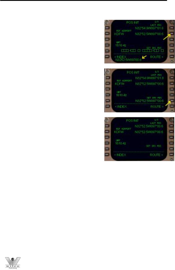
If the IRS is already aligned when you load the panel, the FMC requires no additional setup and its position is already determined from current IRS positions. The important concept to remember here is that the FMC position is the same as the average of the three IRU positions when the aircraft is on the ground. The lat/long listed at the 1R LSK (LAST POS) is the current FMC position when the IRS is fully aligned. If this is the case, you may continue to the ROUTE page by pressing the 6R LSK.
In the picture at right you see a scratchpad message “ENTER IRS POSITION” along with boxes abeam the 5R LSK labeled “SET IRS POS”. This is displayed during alignment of the IRS. During the alignment period, the current lat/long position of the aircraft is entered into the scratch pad and then placed into the boxes at the 5R LSK. This position is transferred to the IRS during alignment.
© Wilco Publishing |
Page 10 of 108 |
767 Pilot in Command
After IRS alignment is completed, the FMC position and the position of all three IRS units will be exactly the same.
The following examples demonstrate how to enter coordinates into the FMC during IRS alignment. These examples assume you understand how to align the IRS as explained in the IRS section.
Starting with the IRS selectors in the OFF position, place all three knobs to the NAV position. Notice that the POS INIT page looks exactly like it does in the picture above. Clear out the ENTER IRS POSITION message in the scratchpad by pressing the CLR key on the FMC keyboard. Now we must enter the aircraft lat/long position into the scratchpad. There are 4 methods to find the coordinates for your current aircraft position. First we will discuss how to find the current aircraft position coordinates. Then we will discuss how to use these coordinates to set the IRS position.
The first method to find your current position is a general method that uses departure airport coordinates. The 2L LSK has a data block listed as REF AIRPORT. This block initially contains “----“ to indicate it is waiting for data input. Notice in the picture at right we have
entered “KDFW” into the data block. You do this by entering “KDFW” into the scratchpad using the FMC keyboard and then pressing the 2L LSK to transfer it into the data block. After entry, lat/long coordinates are listed abeam the 2R LSK. These coordinates represent the airport coordinates for KDFW. These coordinates can be used to set the IRS position to the general vicinity of the aircraft (explained later).
The second method to find your current position is to simply use the LAST POS listed on the POS INIT page at the 1R LSK. Most of the time the LAST POS will be the current aircraft position. If you are sure that this is the case, you can use these coordinates to set the IRS position (explained later).
The third method to find your current position involves using sim charts. If you have sim charts from a third party that list “gate coordinates” for the airport you are departing, you can use these gate coordinates to initialize the IRS position. If you know the exact gate that the aircraft is sitting at, these coordinates (if listed on the chart) may be used. If you do not know your exact gate, any coordinates listed on the chart is sufficient to position the IRS and FMC close to the current aircraft position.
The forth method to find your current position is to use the FS2000 <shift><z> feature. Pressing <shift><z> displays current lat/long position across the top of
© Wilco Publishing |
Page 11 of 108 |

767 Pilot in Command
the screen. You will have to move the overhead display down a bit to reveal the following information (this is an example of what you find):
This gives you the exact position of the aircraft according to the sim. It is important that you enter the coordinates into the FMC in the correct format. Notice the format of the lat/long listed in the REF AIRPORT data block in the previous pictures (abeam 2R LSK). You need to use this exact format for entering the coordinates manually. In our example above, we would translate the FS2000 coordinates to “N3254.9W09701.8” and enter this into the scratchpad. Notice that the “N” coordinate was rounded off and that the “W” coordinate needed to be rounded and interpreted. This is necessary because FS2000 does not list lat/long in the same format as the FMC. To convert the FS2000 coordinates we did the following:
-The “ * “ represents degrees and is dropped from both N and W coordinates.
-The “N” coordinate is rounded off to give you N3254.9
-The “W” coordinate “97*” translates to “097”
-The “W” coordinate “1.79” translates to 01.8 and is combined with the 097 to give you the W09701.8 coordinate.
This last method is the most accurate but perhaps the most difficult and confusing. We recommend this method only to those pilots that are comfortable with lat/long formats.
Any of the four methods discussed above are acceptable for finding coordinates that represent current aircraft position. Once the desired coordinates are found, enter them into the FMC and the SET IRS POS boxes. Entry of the coordinates into the FMC is basically the same for all 4 methods. The general idea is to place the coordinates into the scratchpad and then transfer them into the SET IRS POS boxes. The only variable here is the method used to put the coordinates into the scratchpad. This will be made clear below.
If using methods 3 or 4 to enter coordinates manually, simply use the FMC keyboard to enter the coordinates into the scratchpad. Once this is accomplished, press the 5R LSK to transfer the coordinates to the SET IRS POS boxes. This action clears the scratchpad contents and transfers the coordinates to the 5R LSK data block. After IRS alignment is complete, the SET IRS POS block disappears and the coordinates entered will be listed in the LAST POS data block abeam the 1R LSK.
© Wilco Publishing |
Page 12 of 108 |
767 Pilot in Command
If using methods 1 or 2 to enter coordinates, it is not necessary to enter them using the FMC keyboard.
To use the REF AIRPORT coordinates to initialize the IRS do the following. Press on the 2R LSK to transfer the coordinates listed in the data block into the scratchpad (shown at right). Once the coordinates are in the scratchpad, place the data into the SET IRS POS blocks at 5R by pressing the 5R LSK.
To use the LAST POS coordinates to initialize the IRS, use the same procedure shown above. Except this time press the 1R LSK to transfer the LAST POS coordinates to the scratchpad.
Regardless of which method is used to enter coordinates to the scratchpad, the procedure to enter these coordinates to the SET IRS POS data block is the same. Pressing the 5R LSK transfers the coordinates in the scratchpad to the 5R data block. Upon pressing the 5R LSK, the data blocks change to display the coordinates previously held in the scratchpad. These coordinates are then transferred to the IRS as the current aircraft position.
Once the IRS is fully aligned, the SET IRS POS data blocks disappear and the coordinates
entered are displayed in the LAST POS data block. This is now the current FMC position. This is also the current position of the three IRS units.
With the position initialization completed, leave the POS INIT page and proceed to the next page in the preflight sequence. The ROUTE page is next as indicated by the prompt at the 6R LSK. Pressing the 6R LSK displays the ROUTE page.
There are a few important things to note when initializing your position on the ground. Many times you will find that the EHSI map does not line up exactly with the actual aircraft position (i.e. map shift). For example, when lining up on the runway and seeing that the runway symbol on the EHSI map is not positioned properly. This is not a problem, and can be completely normal, if you did not use the exact aircraft position for IRS initialization. This can also occur if the IRS units are drifting significantly on the ground. In either case, it is important to note that your aircraft is at least “close” to the correct position on the map. Also, during IRS initialization if you try to enter IRS coordinates
© Wilco Publishing |
Page 13 of 108 |
767 Pilot in Command
that are sufficiently different from the FMC LAST POS, the FMC generates a position error message in the scratchpad. Double check the coordinates and try entering them again. The FMC accepts whatever coordinates you enter on the second attempt.
Once you are airborne, the FMC receives a radio update of its exact position. The EHSI map also shifts to reflect the updated aircraft position. Prior to departure, if you find that the IRS positions are just too far off from the actual aircraft position (i.e. runway more than a few miles away from current position), accomplish a quick align of the IRS using the simulators exact position (found by hitting <shift><z>). The quick align procedure is explained in the IRS section of the manual. It is important to start with an accurate IRS position since the IRS cannot be updated in the air, and if your FMC reverts to IRS NAV ONLY, you could get a potentially large map shift.
The “1/3” in the upper right hand corner of the POS INIT page indicates that there are a few more pages available for viewing. These pages do not require data entry and are for reference only. They can be viewed in flight to verify FMC position more accurately.
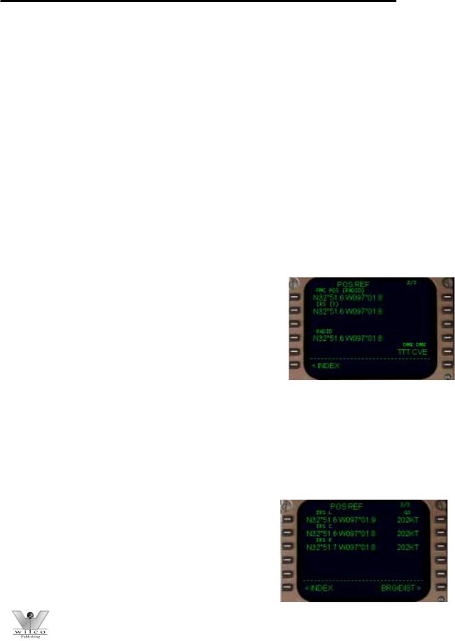
Page 2/3 contains exact position information that the FMC is currently receiving. The 1L data block contains the current FMC position and displays how that position was determined. Notice the “(RADIO)” displayed above the coordinates. This indicates that the FMC is using the currently calculated RADIO position (as determined by cross-checking the automatically tuned VORs). The 4L data block displays this same RADIO position information. These coordinates have been calculated
using the TTT and CVE VOR/DME radials (shown in the 5R data block).
Also listed on page 2/3 is the currently calculated IRS position. The 2L data block contains the IRS position as calculated by the average of the three IRS units. The “IRS (3)” in the 2L data block indicates that the position listed is based on the average of the three IRS positions. If the IRS position were based on less than 3 units, this information would be displayed here. If the FMC reverts to IRS NAV ONLY, a radio position will not be displayed at the 4L data block. If this is the case, the FMC POS data block
annunciates that it is using the IRS position.
Page 3/3 contains 2 pages of data listing exact IRS positions. The first page shows the current lat/long position as well as ground speed for all three IRS units.
© Wilco Publishing |
Page 14 of 108 |
767 Pilot in Command
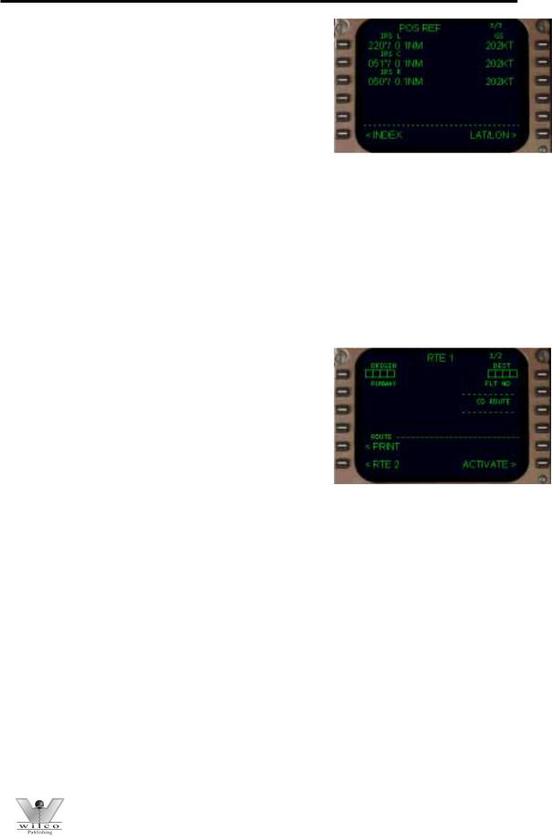
Pressing the 6R LSK displays the BRG/DIST page. This page shows, in bearing and distance, the difference between the presently calculated FMC position and the position calculated by each of the IRS units. From this page you can identify if the IRS units are drifting and how much drift has occurred. Pressing the 6R LSK returns the display to the LAT/LONG format.
ROUTE Page
The ROUTE page can be accessed at any time by pressing the RTE function key on the FMC keyboard. The ROUTE page is used to program the departure airport, departure runway, arrival airport, and route of flight data. The route of flight data consists of “waypoints” that the FMC uses to navigate. A waypoint can be a VOR, an intersection, lat/long coordinates, or a custom made point defined by VOR radials. Custom waypoints are discussed in the LEGS page section.
The FMC is capable of accepting two routes into memory: RTE 1 and RTE 2. Only one route is “active” (or in use) at any given time, with the other route remaining inactive in the FMC memory. Notice that on the top of the ROUTE page it says “RTE 1”. This indicates that these pages are for entry of ROUTE 1. At the bottom of the screen at the 6L LSK is a prompt labeled “<RTE 2”. Pressing the 6L LSK accesses the ROUTE 2 pages for entry of a second route.
Entry of a second route into RTE 2 is optional. One of the uses for RTE 2 includes the programming of an alternate route. This is helpful when planning a diversion routing if arrival at your original destination is not possible. It can also be used for saving the active route prior to executing a change (described later). Our example utilizes RTE 1 for all programming explanations. Keep in mind that programming a route into RTE2 follows the exact same procedure as programming a route into the RTE1 pages.
The first ROUTE page has data boxes for the insertion of the origin (1L LSK) and destination (1R LSK) airports. Also located on this page are data blocks to enter the departure runway (2L LSK), flight number (2R LSK), and the company route name (3R LSK). The company route name is used to load a preprogrammed route into the FMC (explained below). The “ACTIVATE>” prompt at the 6R LSK is used to “activate” the programmed route. It is always displayed at the 6R LSK prior to activation of the displayed route. Only one route can be activated at any one time. Activation of a route is accomplished
© Wilco Publishing |
Page 15 of 108 |

767 Pilot in Command
after programming the route and is explained later in this section. The “<PRINT” prompt at the 5L LSK is for future use and does not work at this time.
There are two ways of entering a route into the FMC; by manually programming the route using the FMC ROUTE page, or by recalling a previously saved route created by the FMC or other flight planning software. Lets begin our discussion of FMC route programming by talking about importing a flight plan from a flight planner. We will discuss how to manually program the route using the ROUTE page of the FMC in just a moment.
Loading Pre-programmed Route Data
The CO ROUTE data block at the 3R LSK is used to load pre-programmed flight data into the FMC. The easiest planner to use is the FS2000 flight planner. After creating a flight plan using the flight planner, save it using a 10-character or less unique file name that contains no spaces or special characters. For example, a flight plan created for a KLGA to KORD flight can be saved as “KLGAKORD01” for easy recall. The use of numbers in the flight plan name permits creating multiple flight plans since you can call subsequent routings “02”, “03”, “04” and so on. After saving the FS2000 flight plan, enter the file name into the FMC scratchpad and press the 3R LSK to enter the name. Please note that it is not necessary to enter the file name extension (i.e. *.pln) since the FMC automatically handles this for you.
Once you have placed the file name into the CO ROUTE data block, the FMC searches the “FS2000\PILOTS” folder for flight plans that have the *.pln extension. If the FMC finds a suitable flight plan, it automatically loads all route data into the ROUTE page. You can view the imported flight plan by looking at each of the route pages using the NEXT/PREV PAGE keys. Refer to the next section called “Activating a route” to find out how to activate the loaded route and how to continue loading FMC data.
The following example demonstrates how to load an FS2000 flight plan into the FMC. The first step is to create a flight plan using the FS2000 flight planner. Staying with our example flight, create a flight from KDFW to KLGA and save it as “KDFWKLGA01”. Make sure that your flight plan is saved to the “FS2000\PILOTS” folder. This is where the FMC looks for stored flight plans.
© Wilco Publishing |
Page 16 of 108 |
767 Pilot in Command
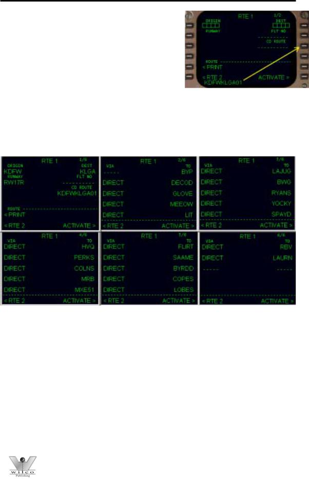
Next, return to the FMC and press the RTE key on the FMC keyboard. This action displays the RTE page. Type “KDFWKLGA01” into the scratchpad using the FMC keyboard. Now press the 3R LSK to transfer the flight plan name to the CO ROUTE data block. This action causes the FMC to search the FS2000/PILOTS folder for a saved flight plan of the same name. If a
properly formatted flight plan is found, the FMC loads all the data into the ROUTE pages automatically. This includes the origin, destination, departure runway, and all waypoints in the route.
Cycling through the route pages using the NEXT/PREV PAGE keys on the FMC keyboard reveals all of the loaded waypoints for the route of flight.
There are now 6 pages of route data loaded into the FMC. Pages 2 through 6 display all of the loaded waypoints. Once activated, these waypoints become the route displayed on the EHSI and are used by the FMC to navigate between KDFW and KLGA.
You are not limited to using only the FS2000 flight planner to create flight plans for import to the FMC. You can create and import flight plans using other third party flight planners provided they use the FS2000 compatible flight plan format. However, you must take the extra step of moving the flight plan created by the third party software into the “FS2000\PILOTS” folder for the FMC to find it. This step is not required if your flight planner already places your flight plans in the “FS2000\Pilots” folder.
© Wilco Publishing |
Page 17 of 108 |

767 Pilot in Command
Manually Programming Route Data
The previous section discussed loading flight plan data created using a flight planner. This section discusses how to program the ROUTE pages manually. To successfully program a route manually you must have a route of flight in mind. A route can be created using any combination of VORs, NDBs, intersections, lat/long points, Victor airways, or Jet airways. The ROUTE page is formatted to accept this data and creates waypoints using the programmed information.
As we previously learned, the FMC can store two routes in memory. We will be working with RTE1 for explanation purposes. When the FMC is initially loaded, there are two ROUTE pages available for RTE1. Page one is programmed with the departure airport, departure runway, and arrival airport. Page two is used to begin manually programming the route.
Pressing the RTE key on the FMC keyboard displays page one of the ROUTE page. Pressing the NEXT PAGE key displays the page shown at right. This page is used to program the route of flight. There are two columns on this page for the entry of route data. The dashed lines in the data boxes abeam the 1L and 1R LSKs indicated where route data can be entered.
Manual route programming always begins with the RIGHT column labeled “TO”. The RIGHT column is used to program individual waypoints. A waypoint is basically a point in the route. Valid waypoints are created from VORs, VOR intersections, NDBs, or latitude/longitude entries. For example, entering “TTT” into the scratchpad and pressing the 1R
LSK makes the TTT VOR the first waypoint in the route. The dashed line now moves down to the 2R LSK for entry of another waypoint. When another waypoint is entered into the 2R
data block, the dashed lines move down to the 3R LSK data block. The FMC continues to accept individual waypoints in this fashion. When the page is filled with waypoints, the FMC automatically adds another ROUTE page that can be accessed by pressing the NEXT PAGE key.
The LEFT column labeled “VIA” is used to program JET and VICTOR airways. The FMC accepts airway names in the LEFT column data boxes. It then automatically adds the waypoints that constitute that airway into the route. For the FMC to accept an airway entry, the airway must be “anchored”. This means you must enter the first waypoint of the airway in the right “TO” column for the FMC to know where the airway begins. For this reason, FMC
© Wilco Publishing |
Page 18 of 108 |
767 Pilot in Command
route programming never starts with an entry in the “VIA” column, it must always start with a waypoint entry in the “TO” column.
The name of the airway is entered into the LEFT column on the line just below the anchoring waypoint entry. The airway must then be “closed” by entering the last waypoint needed in the airway. If you attempt to enter an airway without a valid “anchor” point, the FMC will generate an error message. The same will happen if an invalid “closing” point is entered.
Lets look at an example of airway programming. Using TTT as a starting point, we added some more waypoints in the “TO” column to take us to the TXK VOR. These waypoints were added individually by entering the waypoint name in the scratchpad and pressing the right LSK
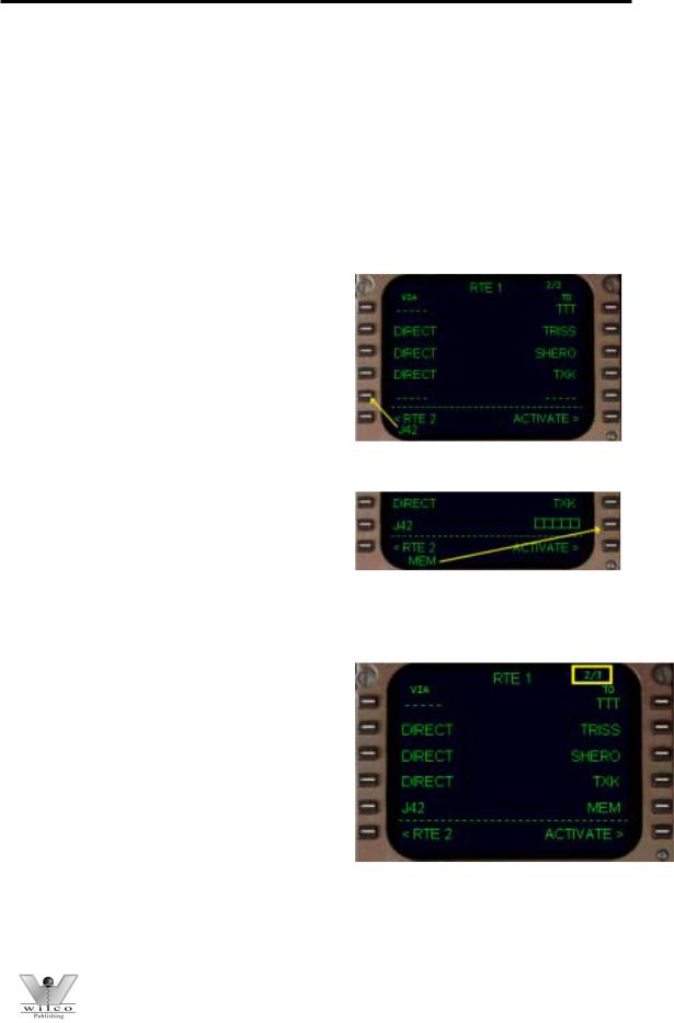
containing the dashed line. From the TXK VOR we want to proceed via J42 to the MEM VOR. Both the TXK VOR and MEM VOR are part of the J42 airway. Therefore, TXK becomes our “anchor” waypoint. Type “J42” into the scratchpad and press the left LSK with the dashed lines (the 5L LSK in our example).
As soon as an airway entry is made in the “VIA” column, the “TO” column automatically displays data entry boxes on the same line. This indicates that a waypoint entry is mandatory for the FMC
to accept the airway in the route. Without a “closing” waypoint entry, the FMC would not know where to stop adding waypoints from the requested airway. To close the airway entry, type “MEM” into the scratchpad and press the LSK abeam the data boxes (the 5R LSK in our example).
The results of our programming are shown at right. The route of flight can be read off exactly as the FMC will draw it. The route starts at the TTT VOR and goes direct to each of the next 3 waypoints. Then after the TXK VOR, the FMC adds to the route all waypoints from J42 up through the MEM VOR.
The waypoints and airways programmed on the route page can be viewed on the LEGS page. The LEGS page lists all waypoints that make up the programmed route, including those from J42. How to access and use the LEGS page is described later in this chapter.
Advanced FMC Route Programming
© Wilco Publishing |
Page 19 of 108 |
767 Pilot in Command
Based on the teachings of the previous section, you should have no problem getting a route programmed into the FMC. However, there are some advanced features of the FMC that can make manually programming the FMC easier. This next example demonstrates these advanced features and also takes you through every step required to properly program the route page manually.
The route programmed in this example is used for the explanation of FMC functions in the next section. Therefore, it is important to run through this example to have the FMC properly setup for future learning. Some of the information provided during this example repeats concepts already described. This is done to reinforce the programming concepts presented earlier.
As previously stated, we shall be programming a flight from KDFW to KLGA. This example demonstrates the use of Standard Instrument Departures (SIDs), Jet airways, waypoints, and Standard Instrument Arrivals (STARs). Our route of flight is as follows:
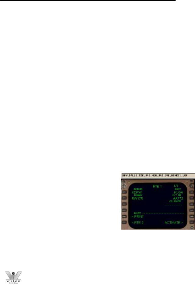
KDFW.DALL6.TXK.J42.MEM.J42.GVE.MINKS1.LGA
To translate: departing the Dallas-Fort Worth International airport via the Dallas6 departure (SID) using the Texarkana transition to the Texarkana VOR, then via Jet 42 to the Memphis VOR, then via Jet 42 to the Gordonsville VOR, then via the MINKS1 arrival (STAR) to the LaGuardia airport.
To begin programming, press the RTE key on the FMC keyboard to access the ROUTE page. All data programmed from previous examples must be removed from the ROUTE page. To do this, press the DEL key on the FMC keyboard followed by the 1L LSK. This removes all route data stored in the FMC.
The data boxes abeam the 1L and 1R LSK indicate that data entry is required in these areas. Therefore, the first information entered on the ROUTE page is the origination and destination airports. The FMC accepts the 4-letter ICAO identifier for each airport. To enter the origin, type “KDFW” into the scratchpad and then press the 1L LSK. To enter the destination, type “KLGA” into the scratchpad and then press the 1R LSK.
The next required entry is the departure RUNWAY in the data block abeam the 2L LSK. In our example we will depart runway 17R. Therefore, type “17R” into the scratch pad and then press the 2L LSK to enter the data. An alternate method to select departure runway using the DEP ARR key will be explained later.
© Wilco Publishing |
Page 20 of 108 |
767 Pilot in Command
The FLT NO data block at the 2R LSK is used to enter the optional flight number. You can enter any combination of letters and numbers to represent your current flight. In our example we are American flight 772, therefore we type “AA772” into the scratchpad and press the 2R LSK to enter the data.
The CO ROUTE data block is not used when manually programming a route. It must remain blank. The RTE 1 page should look exactly as pictured above prior to the moving on to the next step.
Programming of the actual route begins on page 2 of the ROUTE page. Press the NEXT PAGE key to access page 2/2. There are two columns on page 2 labeled “VIA” and “TO”. The right “TO” column
is used to enter individual waypoints in the route. For example, if you wanted to start out going direct to a VOR (or other named waypoint) you would type in the name of the point in the scratchpad and place it in the 1R data box. The dashed line would then move to the 2R position where you can insert the next waypoint in the route. You can continue programming the route
in this fashion until all waypoints have been entered. There are many different valid entries to create waypoints. Please see the “LEGS” page discussion of this manual for details about the valid waypoint formats.
The left “VIA” column is for the entry of Jet and Victor airways. The ROUTE page provides for the insertion of Jet and Victor airways in place of inserting the individual airway waypoints manually. The airway must start with a waypoint entry in the “TO” column. This waypoint must be part of the airway to be entered. Then to complete the airway, the last waypoint of the airway used in the route is entered into the “TO” column. This will be explained later in our example. Please note that the airway database was extracted from the FS2000 database, so there may be some missing airways. This could result in getting an error message when programming an airway. In this case, you would have to enter all of the airway waypoints manually using the “TO” column.
Our route of flight starts with the use of a Standard Instrument Departure (SID). To access the SID page of the FMC you must press the “DEP ARR” key on the FMC keyboard. This calls up the departure/arrival index page. From the DEP/ARR INDEX page you can access the departure and arrival procedures for your origination and destination airports. (Note: For more information about the SID/STAR database, review the “Saving FMC Data” section near the end of the FMC manual).
© Wilco Publishing |
Page 21 of 108 |

767 Pilot in Command
Notice that the index page has prompts for both RTE 1 and RTE 2. Since we are programming with RTE 1, KDFW and KLGA are listed in the RTE 1 index. At this point we want to select a SID for KDFW in RTE 1. Pressing the 1L LSK “<DEP” prompt calls up the departure page for the KDFW airport.
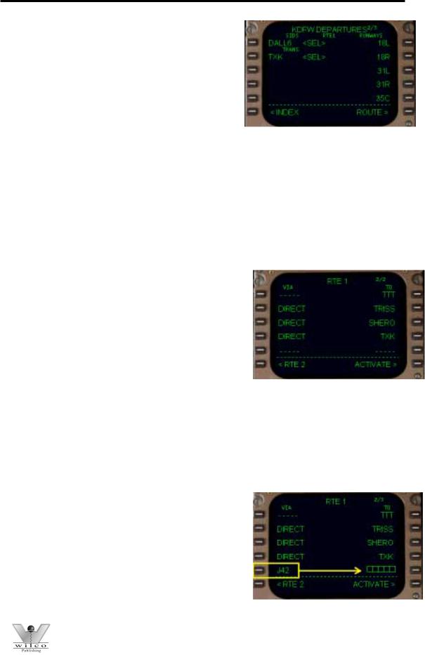
The KDFW departure page is shown here. You can do two things on this page; select a SID, and/or select a departure runway. Notice in the upper right corner that this page is only 1 of 3 pages available. This indicates that there are more pages of SIDs and/or runways available. To access these pages, use the NEXT/PREV PAGE keys on the FMC keyboard.
The available runways are listed on the right side of the page. We previously entered runway 17R using
the ROUTE page, therefore notice the “<SEL>” prompt next to the 17R listing. To change the departure runway from this page, simply press the right LSK abeam the desired runway. For example, press the 3R LSK to select runway 17C for departure. The “<SEL>” prompt would then move up to the 17C data block. The ROUTE page would also change to reflect the new departure runway. Since KDFW has more than just 5 runways, selection of other runways is possible by looking on pages 2 and 3 using the NEXT/PREV PAGE keys on the FMC keyboard.
The available SIDs for KDFW are listed on the left side of the departure page. Notice that there are five available SIDs listed on page 1. More SIDs may be available by looking on pages 2 and 3. Since our route of flight uses the DALL6 departure, press the 1L LSK to select the SID.
Pressing the 1L LSK displays the page shown at right. The selected SID is listed in the 1L data block. Below the selected SID name are the available SID transitions. Not all SIDs have transition procedures. If a SID has no transitions available, the word “<NONE>” is listed in the TRANS column.
Our flight plan calls for the use of the TXK transition. Since we do not see that transition listed on page 1, we must use the NEXT PAGE key to look for it on page 2. Pressing the NEXT PAGE key displays the page shown here. Notice that we are now on page 2/3 and that the TXK TRANS is listed abeam the 3L LSK. To select the TXK transition procedure simply press the 3L LSK.
© Wilco Publishing |
Page 22 of 108 |
767 Pilot in Command
Pressing the 3L LSK results in the remaining TRANS procedures disappearing and a “<SEL>” prompt displayed next to the selected transition.
If a mistake is made in the selected TRANS or even the selected SID, simply start fresh by pressing the “<INDEX” prompt at the 6L LSK.
This redisplays the DEP/ARR INDEX page where you can start the procedure over. If a selected departure is no longer required, or a different departure procedure is desired, selection of a different procedure is possible at any time by returning to the departure page and selecting a new procedure. The FMC will automatically remove the old procedure and place the new procedure into the route. This eliminates the need to manually remove waypoints in the route from the old procedure prior to selecting a new one.
Now that the proper SID and SID TRANS are selected, return to the ROUTE page by pressing the 6R LSK labeled “ROUTE>”. Pressing the 6R LSK takes us to page one of the RTE1 pages. Upon selecting page
2/2 (using the NEXT PAGE key), we find that the waypoints of the selected SID and SID TRANS are now listed in the “TO” column as shown here. This listing differs a bit from the real FMC in that the real FMC would not list all waypoints of the procedure, rather just the name of the procedure and the TRANS fix.
The RTE1 listing shown above is how this page would look if the waypoints had been programmed manually rather than added automatically by selecting a SID. Notice that the dashed lines have moved down to the 5L and 5R LSK positions just below the last waypoint entry. This is where the next airway or waypoint entry would be made. In our example, we are going to join up with J42 from the TXK VOR. Since the TXK VOR is part of J42 it serves as the “anchor” waypoint for the airway. The Jet airway can now be placed in the “VIA” column. Do this by typing “J42” into the scratchpad and pressing the 5L LSK.
Notice in our picture that J42 (highlighted) is now in the VIA column and that a group of boxes has appeared in the TO column. These boxes indicate that the FMC requires a waypoint entry along J42 to complete the insertion of the airway into the route.
© Wilco Publishing |
Page 23 of 108 |
767 Pilot in Command
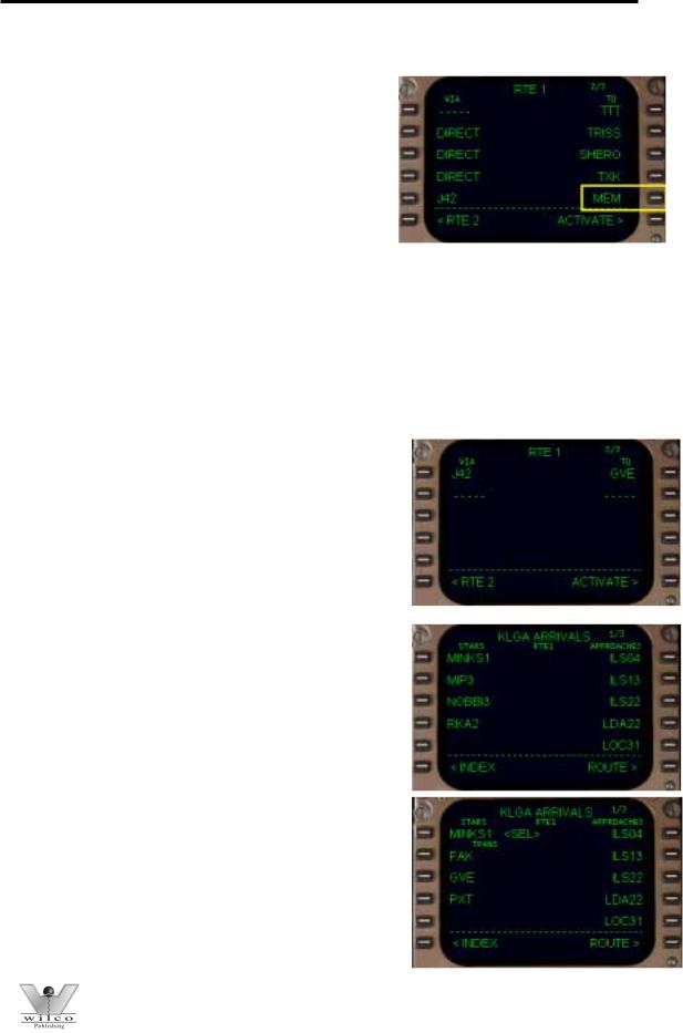
Our flight plan requires that we fly along J42 until reaching the MEM VOR. Type “MEM” into the scratchpad and press the 5R LSK to place it into the data box. Doing so completes the airway entry as
shown here. If an attempt is made to complete an airway entry with a waypoint that is not part of the airway, the FMC will display an INVALID ENTRY message in the scratchpad. If this happens, press the CLR key to remove the error message and then enter the correct waypoint to complete the airway entry.
After the MEM waypoint, the flight plan requires that we continue along J42 until reaching the GVE VOR. Since we have run out of space on page 2, the FMC automatically adds another page to the ROUTE pages. Move to page 3 using the NEXT PAGE key on the FMC keyboard. Page 3 will have the dashed entry lines available abeam the 1L and 1R LSKs for entry of more route data. Use the same procedure as before to enter the next airway in the route page. Type “J42” into the scratchpad and press the 1L LSK. Then type “GVE” into the scratchpad and press the 1R LSK. This completes the Jet route entry.
The resulting page should look exactly as shown at right. The data entry lines have now moved down to the 2L and 2R LSK positions awaiting more data. If more airways (or waypoints) were required in the route, they would be entered here. However, our route calls for a STAR into KLGA. So we need to return to the DEP ARR page using the DEP ARR key on the FMC keyboard.
Press the DEP ARR key to display the DEP/ARR INDEX page. This time select the KLGA “ARR>” prompt at the 2R LSK to display available arrivals. The arrival screen is set up similarly to the departure screen. Available STARs for KLGA are listed along the left side. Available approach procedures and runways are listed on the right side. Approaches and runways will be discussed later in this manual.
Our flight plan calls for the use of the MINKS1 arrival into KLGA. Pressing the 1L LSK selects the MINKS1 arrival and displays available STAR transitions. Since our flight plan uses the GVE VOR, select the GVE TRANS by pressing the 3L LSK. This connects our route to the STAR.
© Wilco Publishing |
Page 24 of 108 |
767 Pilot in Command
If a mistake is made in selecting a STAR or TRANS, return to the INDEX page by pressing the 6L LSK and start again by selecting the KLGA ARR prompt. Also, if at anytime during the flight a different STAR is required, return to the arrival page using the DEP ARR key and make the changes. When changes are made to the STAR, the FMC automatically updates the route to reflect the changed STAR procedure. This eliminates the need to manually remove waypoints added by the previously selected STAR.
Once the STAR is selected, return to the ROUTE page by pressing the 6R LSK labeled “ROUTE>”. Page through the route pages to double check the programmed route using the NEXT/PREV keys. Notice that after the GVE VOR the MINKS1 arrival waypoints have been added as shown at right.
This completes the programming of our example route. When satisfied with the programmed route, the route can be “activated” and the preflight of the FMC can continue.
Activating a Route
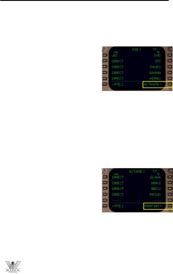
The “ACTIVATE>” prompt at the 6R LSK is used to “activate” a programmed route. Since there are two routes available in the FMC, activation of a route tells the FMC to use the route displayed. After loading or programming a route into RTE 1, press the 6R LSK to activate this route. When the 6R LSK is pressed to activate the route, the EXEC key will subsequently illuminate. Pressing the EXEC key “executes” the requested route activation. In our example, the programmed route in RTE1 is now the active route displayed on the EHSI.
After activating and executing RTE 1, the prompt at the 6R LSK changes to “PERF INIT>”. Pressing the 6R LSK displays the “Performance Initialization” pages. These pages are the next pages that require data entry during the pre-flight programming of the FMC.
Now that route programming is complete and the route has been activated, the route programming can be saved for future recall using the CO ROUTE data block on page one of the ROUTE pages. Information on how to save a programmed route for future recall can be found in the “Saving FMC Data” section later in this manual.
© Wilco Publishing |
Page 25 of 108 |

767 Pilot in Command
Here are some important points to remember when working with routes in the FMC. Since the FMC is capable of accepting two routes into memory (RTE 1 and RTE 2), it is important to remember that only one route can be activated at one time. After activating one of the routes, only the active route is listed on the EHSI. Changes made to the “active” route during flight changes the course followed by the AFDS in LNAV mode. Changes to the “inactive” route do not affect the activated route of flight.
Anytime you are working with the inactive route, the “ACTIVATE>” prompt shall be displayed at the 6R LSK position. Also, when the inactive route is viewed in the FMC, a dotted course is displayed on the EHSI in addition to the currently active “pink” course line. This dotted course line represents the route programmed into the inactive route pages. The AFDS always follows the active (pink) route regardless of the presence of the inactive route course on the EHSI. Changes to the inactive route do not affect the active route.
In our example we activated RTE 1. Pressing the “<RTE 2” prompt at the 6L LSK displays the RTE 2 pages. When viewing the RTE 2 pages, the prompt at 6L changes to “<RTE 1” and when pressed, take you back to the RTE 1 pages. When RTE 1 is the “active” FMC route, an “ACTIVATE>” prompt is displayed at the 6R LSK when viewing RTE 2. This indicates that modifications and additions to the data in the RTE 2 pages can be made without affecting the active RTE 1 pages, or the course followed by the AFDS in LNAV mode.
If at any time in flight you want to use the routing programmed into RTE 2, simply “ACTIVATE” and “EXECUTE” the route as was done with RTE 1. In this case, RTE 1 becomes the inactive route and RTE 2 becomes the active route displayed on the EHSI and followed by the AFDS in LNAV mode.
Here is something else to keep in mind when programming waypoints into a route. There can be many waypoints throughout the world with the same name. Anytime a waypoint is entered into the FMC and is found to have more than one location, the FMC presents you with a
choice of waypoint locations. An example of a waypoint selection screen is shown at right. This screen displays the latitude/longitude of each waypoint option as well as the type waypoint being defined. The first waypoint listed at the 1L LSK is always the waypoint closest to your currently programmed route or aircraft position, and is most likely the waypoint needed for your route.
Pressing the 1L LSK selects the waypoint location shown in the 1L data block for insertion of the waypoint into the route. Pressing any of the other left LSKs selects the waypoint location listed in the corresponding data block.
© Wilco Publishing |
Page 26 of 108 |

767 Pilot in Command
KJFK-KSEA Route Example
Here is a quick example of how to program a different type of route into the ROUTE pages. This example is offered to further solidify your understanding of ROUTE programming. DO NOT DO THIS EXAMPLE NOW! The remaining sections of this manual utilize the KDFW to KLGA route we have already programmed. For now, simply read through these steps to see if you can follow the programming logic. Then, after completing all other sections of this manual, try programming this route into the RTE 1 pages without reference to these instructions. Consider the following route from JFK to SEA:
JFK..GAYEL.J95.BUF..DLH..MOT..GGW..MLP.GLASR3.SEA
-Press the RTE button to display the RTE1 pages.
-Start by filling in the ORIGIN and DEST data blocks. Type KJFK into the scratchpad and press the 1L LSK. Type KSEA into the scratchpad and press the 1R LSK.
-Select a departure runway. In this example we use the DEP/ARR INDEX to do this. Press the DEP ARR key and select the 1L LSK for JFK DEP. Notice there are no departures in the database. Select runway 4R by pressing the 2R LSK. Return to the ROUTE page by pressing the 6R LSK. Notice that RW04R has been entered in the RUNWAY field.
-Enter the optional flight number. Type “AA265” into the scratchpad and press the 2R LSK.
-Press the NEXT PAGE key to start entering the route.
-Type “GAYEL” into the scratchpad and press the 1R LSK. This enters GAYEL intersection as the first waypoint of the route.
-Type “J95” into the scratchpad and press the 2L LSK. This puts Jet 95 in the route starting at GAYEL.
-Type “BUF” into the scratchpad and press the 2R LSK. This completes the J95 airway entry.
-Type “DLH” into the scratchpad and press the 3R LSK. The FMC presents a choice of waypoints. Press the 1L LSK since this is the correct waypoint.
-Type “MOT” into the scratchpad and press the 4R LSK. The FMC presents a choice of waypoints. Press the 1L LSK to choose the correct waypoint.
-Type “GGW” into the scratchpad and press the 5R LSK.
-Press the NEXT PAGE key to move to page 3 of the route page to add more waypoints.
-Type “MLP” into the scratchpad and press the 1R LSK. The FMC presents a choice of waypoints. Press the 1L LSK to choose the correct point.
-Press the DEP ARR key and select the 2R LSK for SEA ARR.
-Press the 3L LSK to select the GLASR3 arrival.
-Press the 2L LSK to select the MLP TRANS procedure.
-Press the 6R LSK to return to the ROUTE page.
-Verify the route by using the NEXT PAGE key to view all pages of the route.
-Press the 6R LSK to “activate” the route.
© Wilco Publishing |
Page 27 of 108 |
767 Pilot in Command
- Press the EXEC key to “execute” the route.
Successful programming of the route results in 4 route pages. The last waypoint in the route page should be the HETHR waypoint (from the GLASR3 arrival). Also the “PERF INIT>” prompt should be displayed at the 6R LSK.
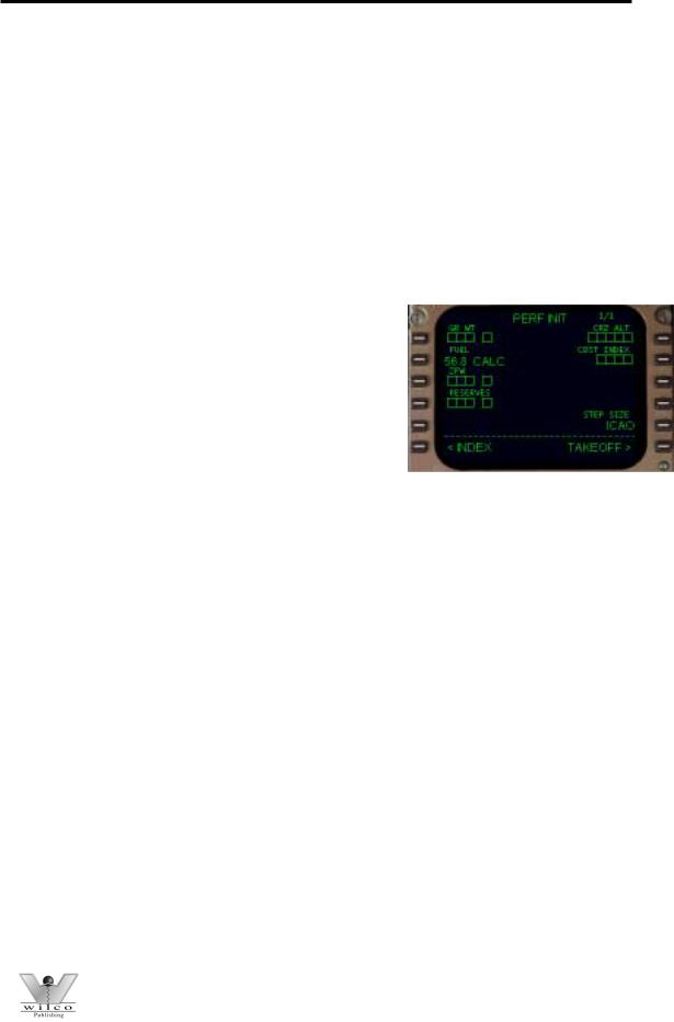
PERF INIT Page
The Performance Initialization (PERF INIT) page is used to enter data required by the FMC to accurately calculate aircraft performance. There is only one PERF INIT page. Most of the data fields contain boxes next to the LSKs. These boxes indicate that data entry is required; otherwise the FMC will not be able to properly calculate performance numbers. The data fields in the PERF INIT page are as follows:
GR WT: Aircraft gross weight (in thousands). This is automatically calculated using the FUEL and ZFW data fields.
FUEL: Aircraft fuel weight (in thousands). The “CALC” indicates that the fuel value in the data block has been “calculated” by the FMC
automatically. The pilot can input a fuel number manually by entering the value into the scratchpad and pressing the 2L LSK. When a manual fuel weight has been entered, “MANUAL” will be displayed in place of “CALC” next to the fuel quantity value. To return the fuel value to an FMC calculated value, press the DEL key (DELETE is displayed in the scratchpad) and press the 3L LSK. This removes the MANUAL fuel value in favor of a new CALC fuel value.
ZFW: Aircraft zero fuel weight (in thousands).
RESERVES: Required reserve fuel (in thousands). This value represents the minimum fuel required before an insufficient fuel warning is generated by the FMC. If the FMC predicts that you will arrive at your destination with less than the fuel quantity entered, an INSUFFICENT FUEL message is generated.
CRZ ALT: Cruise altitude. Enter the desired cruise altitude.
STEP SIZE: For VNAV altitude calculations, ICAO indicates standard “step to” altitudes. An entry of “0” inhibits automatic step altitude programming. This is discussed further in the VNAV section.
COST INDEX: This value is used by the FMC to predict economy performance. A lower cost index means better economy versus a high cost index. A standard cost index for the 767 is 80.
© Wilco Publishing |
Page 28 of 108 |
767 Pilot in Command
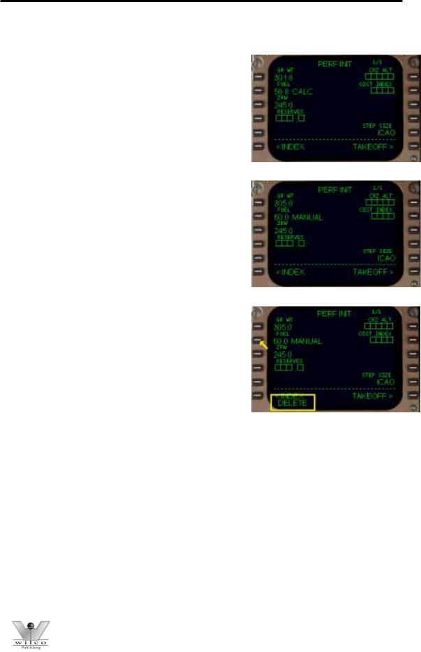
Start programming the PERF INIT page by entering the aircraft’s “zero fuel weight” (or ZFW) into the 3L data block. This is the weight of the aircraft plus payload but without fuel. The ZFW of our
aircraft is always 245,000 lbs. Therefore, type “245” into the scratchpad and press the 3L LSK to enter the data.
With the entry of a ZFW in the 3L data block, the GR WT data block is automatically filled by the FMC. Changing the GR WT field manually would conversely update the ZFW data block.
Making changes to the FUEL value will cause the GR WT to update as well. In the picture at right, notice that a manual fuel value has been entered into the FUEL data block. Also notice the GR WT field has updated as well. To restore the FUEL value to the FMC calculated value, press the DEL key on the FMC keyboard and then press the 2L LSK. This removes the manually entered fuel weight and restores the FMC calculated value.
Depending on how you start the sim, the CALC fuel value may or may not reflect the actual amount of fuel on the aircraft. To correct an incorrect CALC fuel entry, put in a manual fuel value and then delete it as described above. This causes the FMC to update the CALC fuel value to the actual amount of fuel on board.
Program the desired reserve fuel weight into the 4L data block. Our example flight to KLGA requires 9,800 pounds of reserve fuel. Enter “9.8” into the scratchpad and press the 4L LSK to enter the data.
Program the desired cruise altitude into the 1R data block. Our flight will cruise at 37,000 feet. You may enter this in one of three ways: 37000, 370 or FL370. Any of these three entries results in FL370 being listed in the CRZ ALT data block. For our flight type “37000” into the scratchpad, then press the 1R LSK to enter the data.
© Wilco Publishing |
Page 29 of 108 |

767 Pilot in Command
The last item to be programmed on the PERF INIT page is the cost index. Enter the standard value of 80 into the scratchpad and press the 2R LSK to enter the data.
This completes the PERF INIT page data entry. Pressing the 6R LSK displays the TAKEOFF page. The TAKEOFF page is the final page that requires data entry prior to completing FMC pre-flight programming.
Here are some points to consider about the PERF INIT page. It should not be necessary to access the PERF INIT page once airborne. The only time it may be required to visit this page in flight is if a fuel quantity error is received. In flight, the FMC continually compares the calculated fuel value to the actual fuel on the aircraft. If a significant difference exists between the two fuel quantities, an FMC scratchpad message is generated. To eliminate this message you can update the erroneous CALC fuel quantity using the procedure described previously.
TAKEOFF Page
The Takeoff page is a reference page that displays the Vspeeds used for takeoff. This page is also used to select a temperature for calculation of reduced power takeoffs.
The permissible flap settings for takeoff in a 767-300 are 5 and 15 degrees. Putting either 5 or 15 into the 1L data block causes the Vspeed column along the right side of the CDU to update with the takeoff Vspeeds for the current aircraft gross weight.
Once a takeoff flap setting has been entered, the Vspeeds can be automatically set on the airspeed gauge. Pressing on the invisible mouse click area at the bottom left corner of the airspeed gauge updates the airspeed bugs based on FMC data. For more information about this feature, see the “Flight Instrument” section of the systems manual.
To set up the FMC for a reduced power takeoff, enter into the THRUST data block (2L LSK) a temperature value between the current outside temperature and 64°. This is called the assumed temperature. A higher assumed temperature results in a greater reduction in takeoff power. The Vspeeds are also updated with the selection of reduced power thrust. The temperature
© Wilco Publishing |
Page 30 of 108 |
 Loading...