

Page 1
G
REATNAVALBATTLES
User’s Manual
™
V
OLUME
IV:BURNING STEEL
This product has been rated by the Entertainment Software Rating Board. For information about the ESRB
rating, or to commentabout the appropriateness ofthe rating, please contactthe ESRB at 1-800-771-3772
Page 2

CONTENTS
INTRODUCTION ................ i
PLAYER’S GUIDE ............... 1
♦
Selecting Game Options........ 1
Game Options Menu .......... 1
SCENARIOS..................... 3
COMMON DISPLAYFEATURES.... 8
♦
Status Bar .................... 8
♦
Message Bar .................. 8
♦
Buttons, Panels,
Screens and Windows......... 8
♦
Using the Mouse .............. 8
MENU BAR..................... 9
♦
Files Menu .................. 10
Credits (Alt–C) .............. 10
Save Game (Alt–S) ........... 10
Quit (Alt–Q)................. 10
Exit to DOS (Alt–X)........... 10
♦
Controls Menu............... 11
Sound (Alt–V) ............... 11
Messages (Alt–M) ............ 11
Time (Alt–T).................11
Pause Game (Alt–P).......... 11
Memory Use (Alt–Z).......... 11
Options (Alt–O).............. 12
Customizer (Alt–U) .......... 12
View Control (Alt–I).......... 17
♦
Stations Menu ............... 17
♦
Reports Menu................ 17
Statistics (Alt–F1) ............ 17
Victory (Alt–F2).............. 17
Visibility (Alt–F3) ............ 17
Reinforcements (Alt–F4) ...... 17
♦
Briefings Menu............... 18
Ships (Ctrl–F1) .............. 18
Aircraft (Ctrl–F2) ............ 18
Guns (Ctrl–F3) .............. 18
Torpedoes (Ctrl–F4).......... 18
COMMANDING TASK FORCES
AND SHIPS.................... 19
♦
Flagbridge Station ............ 19
Map Panel.................. 20
Flagbridge Control Bar ....... 24
♦
Ship Bridge Station ........... 35
Air Operations Button
and Panel .................. 36
Damage Button and Panel ... 37
Gun Button and
Gunnery Panel .............. 39
Nav Button and
Navigation Panel............ 41
Torp Button and
Torpedo Panel .............. 41
♦
Main Gunnery ControlStation .. 43
Gunnery Basics.............. 43
Director Control Layout ...... 44
Individual Turret Controls.... 50
♦
Secondary Gunnery Control . . . 53
♦
Torpedo Station.............. 53
Torpedo Basics .............. 53
View Bearing Indicator....... 55
Magnification Thumb Control.55
Magnification Level Readout.. 55
Page 3

Mount Selection Controls ..... 55
Compass Dial ............... 55
Auto / Manual Switch ........ 56
Reload Readouts............. 56
Target Readout Control....... 56
Torpedo Activation Switches .. 56
Torpedo Ready Lights ........ 57
Fire Button ................. 57
Spread ..................... 57
Torp Set Knob............... 57
Torpedo Range Readout ...... 58
Speed Readout .............. 58
Fire Angle Readout
and Controls................ 58
Target Speed Readout ........ 58
Target Range Readout........ 58
Target Heading.............. 58
Damage Indicators........... 58
♦
Air Operations Station ........ 59
Air Operations Control Bar.... 59
Summary Panel ............. 60
Aircraft Information ......... 61
Formation Information....... 62
Ready Button and
Ready Aircraft Window....... 62
Unready Button and
Unready Aircraft Window..... 65
Launch Button and
Launch Aircraft Window ..... 65
♦
Damage Control Station....... 66
Damage.................... 66
Damage Station Control Bar .. 67
Damage Control Party Icons .. 68
Pumps ..................... 68
Deck Display................ 69
Compartment DamageReport.. 70
Flooding Button and Panel ... 72
Structure Button and Panel ... 73
Effects of Damage............ 73
♦
Lookout Station .............. 75
♦
Sub Operations Station........ 76
Map Panel.................. 77
Submarine Orders ........... 77
♦
Bases ....................... 77
Base Station ................ 78
♦
The Environment............. 82
Beaufort Scale............... 83
Visiblity .................... 84
GNB4 SCENARIO EDITOR ...... 85
♦
Getting Started............... 85
♦
Menu Bar.................... 86
Buttons and Windows........ 86
Using the Mouse............. 86
♦
Controls Menu............... 87
Description Menu (Alt–D)..... 87
Date / Time Menu (Alt–T)..... 87
Weather Menu (Alt–W) ....... 87
♦
Screens Menu................ 87
Base Screen ................. 88
TF (Task Force) Screen ....... 97
Submarine Operations
Screen .................... 102
♦
Reports Menu............... 104
Visibility .................. 104
Reinforcements ............ 104
Bases ..................... 104
Task Forces ................ 104
Ships ..................... 104
♦
Briefings Menu.............. 104
Page 4

INTRODUCTION
Great Naval Battles IV (GNB4) expands the scope of SSI’s acclaimed line of naval simulators to include
World War II naval actions in many of the theaters that saw the shadow of the battle wagon. From the
frigid Barents Sea to the balmy Mediterranean, the North Atlantic and the English Channel, the Allies
can be pitted against Axis forces in one-day battle scenarios or longer campaigns. The Axis forces
include the German, Italian and French navies, while U.S., British, and Soviet ships are available on
the Allied side.
In addition to increasing the scope of the game, several new features and improvements have been added:
♦
REATNAVALBATTLESVOL
The G
. IV Customizer allows alterations in game variables to reflect the preferences
of the Commander-in-Chief.
♦
A tactical view panel on theFlagbridge,Ship Bridge, and Air Operations stations showsthe action as it happens.
♦
Radar is now available for ships and bases.
♦
The types of ships and planes for both the Allied and Axis sides have been expanded.
♦
Submarine operations have been added.
♦
The addition of a Random Battle Generator, with ten orders of battle for each side, means that over 100
random scenarios for either surface or carrier actions can now be fought.
♦
The level of realism has been increased by adding structural damage ratings for all ships.
i
I
NTRODUCTION
Page 5

PLAYER’S
GUIDE
This section contains the information you need to play G
REATNAVALBATTLESVOL
. IV. It is written for a mouse-
equipped machine, but you can also use keyboard equivalents for most of the game functions.
If this is your first experience with a G
REATNAVALBATTLES
series game, a tutorial scenario has been provided
in a PDF (Portable Document File) and can be viewed through the Adobe Acrobat™ Reader. In order to
become familiar with many of the options and commands, we recommend that you play this scenario at
least once before trying one of the historical scenarios.
S
ELECTINGGAME
O
PTIONS
REATNAVALBATTLESVOL
G
. IV includes a variety of scenarios and game features. As you begin a new game, you
are given the opportunity to select from the available options in a series of menus. Each menu presents one
basic choice, and the menus progress in logical order, reflecting the choices you make.
Game Options Menu
This menu enables you to choose the game that you want to play. G
choice of historical scenarios, scenarios that you create using the GNB4 S
scenario. You may also load a saved game or exit to DOS.
If you decide to change your choices, left-click on the CANCEL button on the current screen to return to the
game options menu.
REATNAVALBATTLESVOL
CENARIOEDITOR
, or a random
. IV offers the
Difficulty Levels
Once you make a scenario selection, you are offered a choice of difficulty levels:BEGINNER, INTERMEDIATE,
ADVANCED, and EXPERT. The harder you set the level, themore the computer opponent receives an advantage
in material, rate of fire, and accuracy.
Beginner
All enemy ships are visible on the map panel, even before your task forces, ships, submarines, or partisans
make contact. They appear as grey task forces or ships. Your side’s spotting ability is at the highest setting.
Play at this setting for a while until you can familiarize yourself with the controls.
1
P
LAYER’SGUIDE:SELECTINGGAMEOPTIONS
Page 6

Intermediate
Enemy ships and planes do not appear on the map panel until contact is made. Spotting ability is equal for
both sides and contact with the enemy is more easily broken. This makes for an even fight.
Advanced
Spotting ranges for your side are decreased and contact is more difficult to maintain once the enemy has
been spotted. The artificial intelligence (AI) for the enemy side is enhanced. This should be challenging.
Expert
Contact range is decreased even more, contact is broken easily, but the enemy’s ability to see your forces is
increased. The enemy’s AI, accuracy, rate of fire, and resupply levels are at their highest levels. Good luck,
you’ll need it.
Select Side
Select the side you want to play, either Allied or Axis.
2
P
LAYER’SGUIDE:SELECTINGGAMEOPTIONS
Page 7

SCENARIOS
Select Scenario
The scenarios that are included G
the European theaters, from the initial successes of the Axis in 1941 to the overwhelming power of Allied
fleets in 1944.
♦Tutorial
TIME
: May 1, 1941
AXIS FORCE
: BB Bismarck, CA Prinz Eugen
LOCATION
This is a straightforward shooing match between the German vessels Bismarck and Prinz Eugen versus the
Hood and Prince of Wales of the Royal Navy. This scenario allows for familiarization with most of the ship
system, particularly navigation and gunnery.
♦Oran
TIME
: July 3, 1940
AXIS FORCE
ALLIED FORCE
: BB Bretagne, Dunkerque, Strasbourg, Richelieu, 4 cruisers, 13 destroyers
LOCATION
: CV Hermes, BBBarham, Malaya, Warspite, RoyalSovereign, Resolution, 7 cruisers, 17 destroyers
After the fall France, the British destroyed the French fleet rather than letting it fall into Axis hands. What if
the French had been ready and waiting?
♦Battle of the Denmark Straights
TIME
: 5:45A.M. May 24, 1941
AXIS FORCE
: BB Bismarck, CA Prinz Eugen
One of the most famous naval engagements of the World War II. The German raiding force attempting to
breakout into the convoy lanes of the North Atlantic is detected by British Cruisers. The German ships
nearly escape from their shadowers, but on the morning of May 24 they are intercepted by a British
battleship group.
REATNAVALBATTLESVOL
. IV give you the full spectrum of naval warfare in
: North Atlantic
ALLIED FORCE
: BB Hood, Prince of Wales
: Algerian coast, Western Mediterranean
LOCATION
: Denmark Straights between Iceland and Greenland.
ALLIED FORCE
: BB Hood, Prince of Wales, CA Norfolk, Suffolk
continues...
3
S
CENARIOS
Page 8

♦Battle of the River Plate
TIME
: 6:14A.M. December 13, 1939
AXIS FORCE
: BB Graf Spee
ALLIED FORCE
LOCATION
: Mouth of the River Plate, west of Montevideo, Uruguay.
: CA Exeter, Ajax, Achilles
The Graf Spee’s voyage across the South Atlantic had been extremely successful; 50,000 tons of shipping had
been captured or sunk. The Graf Spee’s captain has decided to head for home, but on the way he will make
one more attack on Allied shipping in the River Plate area. The British area commander predicts this move
and positions his Cruiser force in the same area.
♦PQ-17
TIME
: July 5, 1942
AXIS FORCE
: BB Tirpitz, CA Hipper, Scheer
LOCATION
: Barents Sea, north of Norway
ALLIED FORCE
: Convoy and destroyer escorts
The battleship Tirpitz was used as a commerce raider on convoys bound for Archangel. Allied convoys that
spotted the Tirpitz usually scattered, which only made the task of their destruction easier for the wolfpacks
and bombers out of Norway. In this hypothetical scenario, convoy PQ-17 has decided to make a run for it in
a group, pursued by the Tirpitz and the cruisers Hipper and Scheer.
♦Gibraltar
TIME
: July, 20 1940
AXIS FORCE
: CV Bearn, BB Provence, Richelieu, Dunkerque, Strasbourg, Conte Di Cavour, Guilio Cesare,
Littorio, Vittorio Veneto, 11 cruisers, 20 destroyers, 5 transports
LOCATION
: Western Mediterranean
ALLIED FORCE
: CV Hermes, Formidable,
BB Barham, Malaya, Warspite, Resolution, Revenge, 9 cruisers, 17 destroyers
The combined forces of the Italian and Vichy French navies hope to make a quick strike and capture the
fortress of Gibraltar. The British have other plans.
♦Atlantic Convoy Run
TIME
: May 1, 1940
AXIS FORCE
: CV Graf Zeppelin, BB Scharnhorst, 4 cruisers, 5 destroyers
LOCATION
: Barents Sea, north of Norway
ALLIED FORCE
: CV Furious, Eagle,
BB Warspite, Nelson, 6 cruisers, 10 destroyers, 6 transports
The supply runs in the Atlantic were vital in keeping the British in the war. The Kriegsmarine sends out a task
force with the Graf Zeppelin to handle one such run.
4
S
CENARIOS
Page 9

♦Battle of Matapan
TIME
: 07:22A.M. March 28, 1941
AXIS FORCE
: BB Vittorio Veneto, 8 cruisers, 13 destroyers
LOCATION
: Mediterranean Sea
ALLIED FORCE
: BB Warspite, Barham, Valiant,
CV Formidable, 4 cruisers, 12 destroyers
The main aim of the British fleet in the Mediterranean had been to engage the Italians in a major surface
action since the entry of Italy into WWII. The Italian fleet sortie at the end of March, 1941 gave the British the
chance they had been seeking.
♦Battle of the North Cape
TIME
: 8:34A.M. December 26, 1943
AXIS FORCE
: BB Scharnhorst, 6 destroyers
LOCATION
ALLIED FORCE
: Barents Sea, north of Norway.
: BB Duke of York, CA Norfolk, Belfast, Jamaica,
8 destroyers
The German Navy attempted to cut the Arctic convoy route with any available ships. By the end of 1943 the
Battleship Scharnhorst was the only major unit ready for action. With an escort of modern destroyers she
sortied into the convoy routes. The Royal Navy had advance knowledge of this attack from Ultra codebreaking and was ready for the Scharnhorst.
♦Leningrad
TIME
: August 8, 1941
AXIS FORCE
: German North Sea Fleet
LOCATION
: Baltic Sea
ALLIED FORCE
: Soviet Baltic Fleet
The Germans have been able to build a sizable attack force in the Baltic, having been spared the heavy losses
in Norway in this hypothetical scenario. The Soviet fleet, based in Riga and Leningrad, are all that stand in
defense of the northern port.
continues...
5
S
CENARIOS
Page 10

♦Battle of the Barents Sea
TIME
: 6:00A.M. December 30, 1942
AXIS FORCE
: BB Lutzow, CA Hipper, 6 destroyers
LOCATION
: Barents Sea, north of Norway
ALLIED FORCE
: CA Sheffield, Jamaica, convoy with 4 destroyers
The Arctic convoys were a major supply route to Russia for supplies from Britain and the US. The German
surface navy in 1942 was mostly positioned to threaten this route, and in this case a force attempted to intercept convoy JW51B, which was only lightly covered by destroyers and two cruisers.
♦Battle of Toulon
TIME
: June 15, 1940
AXIS FORCE
: BB Conti Di Cavour, Giulio Ceasare, Andrea Doria, Cario Duilio, Littorio, Vittorio Veneto,
11 cruisers, 24 destroyers
LOCATION
ALLIED FORCE
: French coast, Western Mediterranean
: BB Courbet, Richelieu, Dunkerque, Strasbourg, 8 cruisers,
28 destroyers
With the fall of France imminent, Italy joins the Axis with its eye on the French fleet. In defiance of orders
from the Vichy government to surrender to the Italians, the French navy intends to put up a fight.
♦Trafalgar II
TIME
: September 10, 1942
AXIS FORCE
: CV Bearn, BB Bretagne, Provence, Lorraine, Dunkerque, Strasbourg, Richelieu, Courbet,
12 cruisers, 31 destroyers
LOCATION
ALLIED FORCE
: Barents Sea, north of Norway.
: CV Courageous, Arc Royal, Illustrious, BB Queen Elizabeth,
Royal Sovereign, Royal Oak, Warspite, Repulse, Nelson, Rodney, King George V, Renown, Valiant,
14 cruisers, 28 destroyers
What if France had fought back and been able to push the Germans out in 1941? Still angered at the British
attempt to destroy her fleet at Oran in 1940, the resurgent French take on the Royal navy.
continues...
6
S
CENARIOS
Page 11

Campaigns:
♦Jutland ‘40
TIME
: October 10, 1940
Unable to achieve air superiority over Britain, the Germans turn to the Kriegsmarine to cripple England.
With help from the Vichy French, the Germans hope to fare better than they did in 1914.
♦Operation Mercury
TIME
: August 12, 1942
The island of Malta served as a major supply port for Allied operations in North Africa. This hypothetical scenario represents an Axis attempt to eliminate this thorn from General Rommel’s side using the Italian navy
with air support from the Luftwaffe. Once done, the Allied war effort in North Africa should grind to a halt.
♦Black Sea
TIME
: June 12, 1942
As the Germans push through southern Russia on land, the Italian and French navies meet the Soviets and
the remainder of the British Mediterranean fleet in the Black Sea. With the Axis in firm control of the
Mediterrainean, the Turks have joined the Axis and provided a base in Istanbul.
♦Operation Sealion
TIME
: September 8, 1940
This hypothetical scenario pits the forces of the German Kreigsmarine against the Royal Navy in a winnertake-all match to decide the fate of the British Isles. Operation Sealion would have been the logical result had
the RAF lost the Battle of Britain to the Luftwaffe; this is why the Germans have air superiority in the form of
air cover flying from bases in France.
LENGTH
LENGTH
LENGTH
LENGTH
: 10 days
: 18 days
: 21 days
: 22 days
LOCATION
LOCATION
LOCATION
LOCATION
: The North Sea
: The Central Mediterranean
: The Black Sea
: The English Channel
7
S
CENARIOS
Page 12

COMMON
DISPLAY
FEATURES
Two display bars are shownatmost stations, one at thetopof the screen and oneatthe bottom. They contain
general purpose information and controlsthatare not specific to anyparticularstation. There is also amenubar
which allows access to manyimportantgame controls (see the menubarsection below). There are avarietyof
displays shown throughout the gamewhichare controlled using a varietyofbuttons and mouse commands.
S
TATUSBAR
M
ESSAGEBAR
B
UTTONS
P
ANELS,SCREENS
AND
W
INDOWS
U
SING THE
M
OUSE
The Status Bar appears at the top of the Flagbridge, Ship Bridge,andAir Ops stations. It shows the name of the
current station, the date, the time of sunrise and sunset, and the wind and visibility conditions.
The Message Bar is at the bottom of the Flagbridge, Ship Bridge, Main Gun Control, Secondary Gun Control, Torpedo, Damage,
Air Operations and Lookout stations. It features displays which show the last message received, the name ofthe
currently selected task force or of the currently selected ship, and the current time. The “x1” button opens a
window for changing the game speed setting. The red STOP button pauses and the green GO button resumes
the game. Messages are controlled by the scroll arrows at the left end of the display area. The next display is
the currently selected task force (TF) which can be changed with the scroll arrows. The speed of play and
pause status can be accessed by left-clicking on them.
Many functions inG
,
REATNAVALBATTLESVOL
. IV and the GNB4 S
CENARIOEDITOR
utilize radio buttons, which
usually toggle items, and larger rectangular buttons, which frequently open up windows. Many windows
have two buttons, OK and CANCEL, which complete the current operation or abort the current operation
and return to the previous screen.
A screen is a full-sized change, apanel is a discrete area within a screen (which may change when a button is
left-clicked), a control is an area within a panel, and awindowis something that pops up in response to a
command or pressing a button.
The mouse buttons can be used three different ways:
Left-Click: This means moving the cursor over something on the screen and pressingthe left mouse button
once. This is how most buttons, both radio and rectangular, are used.
Double Left-Click: This means moving the cursor over something on the screen and pressing the left mouse
button twice quickly. This is how most items on lists are selected.
Right-Click: This toggles the menu bar on and off.
8
C
OMMONDISPLAYFEATURES
Page 13
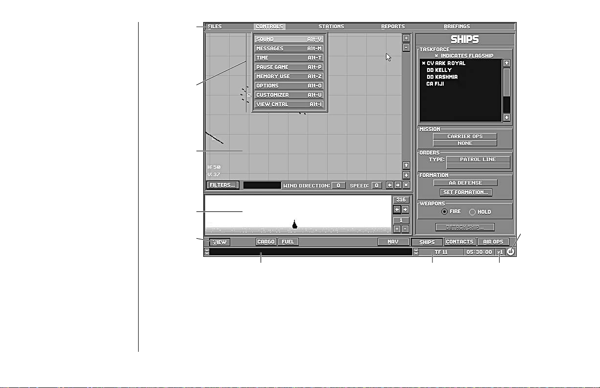
MENU BAR
menu bar
controls
menu
map panel
view panel
pause/resume
game
status bar
game speed buttoncurrent TFmessage bar
The menu bar gives you quick access to a variety of game functions. It appears at the top of the screen when
you right-click or press Esc and can be closed by right-clicking or pressing Esc a second time.Note: While the
menu bar is active, all other game controls are inactive until the menu bar is closed.
9
M
ENUBAR
Page 14

F
ILESMENU
The options on theFILES menu deal mostly with issues that are external to the game such as saving games,
quitting a scenario and exiting to the operating system.
Credits(Alt–C)
This option provides you with the game credits and current version number.
SaveGame(Alt–S)
This option enables you to save a game in progress so that you can quit and resume it later. Each saved game
uses at least 380K of disk space.
Quit (Alt–Q)
This option enables you to leave the current scenario.Note: The game does not return directly to DOS, but
instead gives you a victory report and an opportunity to start another game or load a saved game
if you desire.
Exit to DOS (Alt–X)
This option enables you to leave the game completely and return to the operating system.
10
M
ENUBAR:FILESMENU
Page 15

C
ONTROLSMENU
The CONTROLS menu offers options that affect the overall play of the gamesuch as sound, message delay,
game speed and the Customizer.
Sound (Alt–V)
This option controls the game sound. You can turn the sound, music, or voice controls on or off.
Messages(Alt–M)
This option enables you to select whether messages are accompanied by sounds, and whether the game
automatically pauses or simply delays briefly to give you time to read them. You can set the delay time
from1–9seconds.
Time(Alt–T)
This option enables you to specify the pace at which the action happens, with “1” being real time and the
other values being accelerated time (“2”, “3”, or “A”; “A” being the highest speed your microprocessor can
run the game). Some controls or views may not display any changes at higher time levels. There is a button
in the lower right-hand corner which displays “1” through “A” that can also access this function by
left-clicking on it.
PauseGame(Alt–P)
This option enables you to suspend and restart the game. Its effect is to toggle the game clock on and off.
Note: All game controls continue to function during the pause, so you can pause, input orders, and then
resume. The red STOP and green GO buttons in the lower right-hand corner serve the same purpose.
Memory Use(Alt–Z)
This displays the status of your computer’s random access memory. It is useful to the SSI Technical Support
Staff if you experience difficulties running the game. There are no user selected controls on this screen.
11
M
ENUBAR:CONTROLSMENU
Page 16

Options (Alt–O)
This window contains four different “reality level” settings, which can be toggled on or off by using radio
buttons. The Aground and Collision buttons control whether or not ships can hit submerged portions of
coastline or each other. Auto Combat lets the computer run the battle for you at a greatly accelerated pace.
Base Search automatically readies and launches available aircraft assigned to all bases. The aircraft automatically conduct Search missions, and report all contacts. See the section on Air Ops on page 14 for more
information about search missions.
Customizer (Alt–U)
The Customizer is a powerful tool for controlling the values used by G
variable levels of historical accuracy for either side during an engagement or campaign. Settings for each
side, Axis or Allied, are changed using the Choose Side control. Four different groups of settings can be
changed by the buttons on the Modes control to change values for Air Ops, Campaign, Tactical, and
Weapons customization. These buttons are constant while the Customizer screen is active. Each group of
settings has several panels with five buttons that range from the least effective setting to the most effective.
Settings can be saved by using the SAVE button, and entering a name for that group of settings on the
SAVE CUSTOM menu that appears. There is also a LOAD button which calls up the list of saved settings.
Double left-click, or highlight and press Enter, on the name of the group of settings to be loaded. Once a
group of settings has been chosen or loaded, left-click on the OK button to activate those settings and return
to the game.
REATNAVALBATTLESVOL
. IV to reflect
12
M
ENUBAR:CONTROLSMENU
Page 17
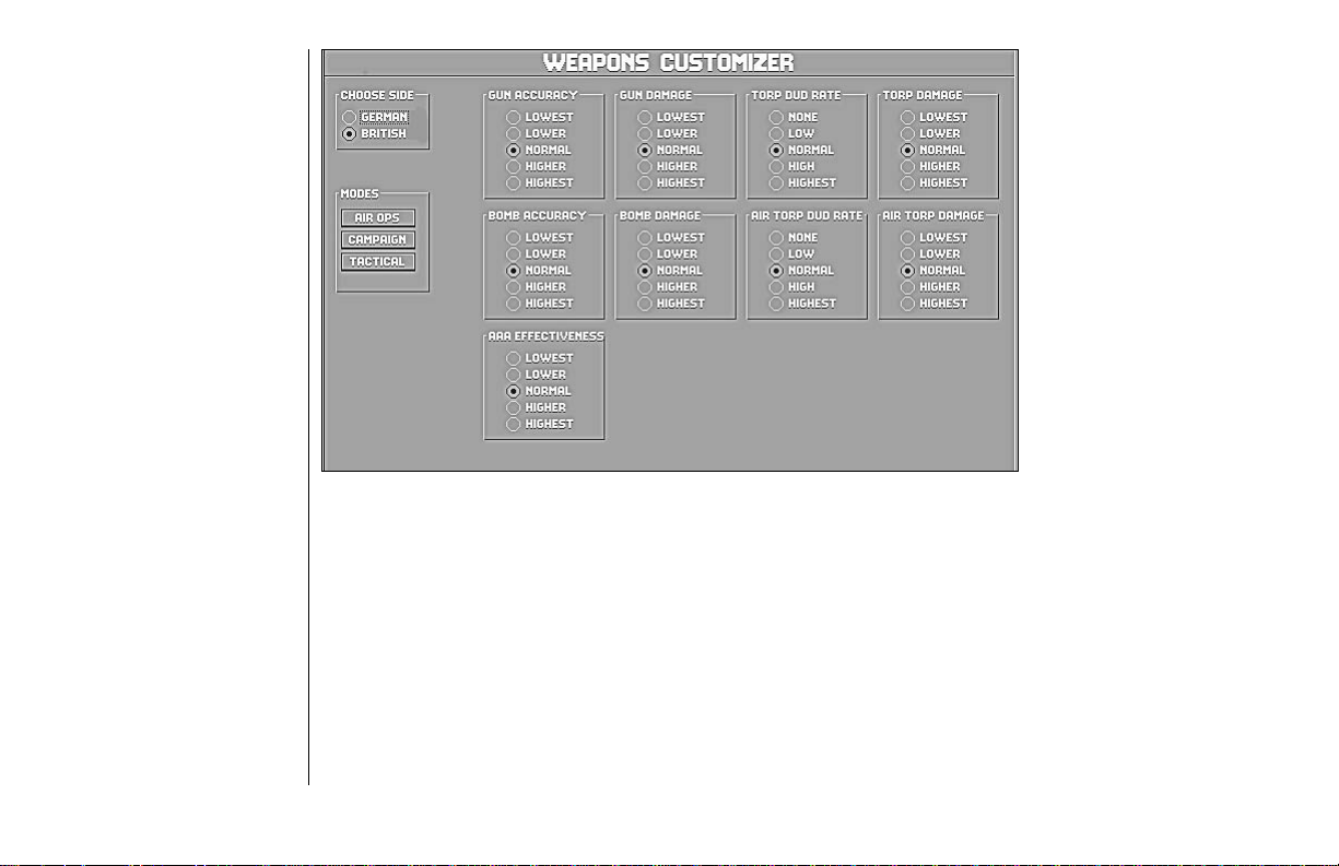
Weapons
The Weapons screen is
the initial screen which
appears when the
Customizer is activated.
The nine panels on this
screen control Gun
Accuracy, Bomb Accuracy,
Anti-Aircraft Artillery
(AAA) Effectiveness, Gun
Damage, Bomb Damage,
Torpedo Damage, Air
Torp Damage, Torp Dud
Rate and Air Torp Dud
Rate. The damage and
accuracy panels have a
range of five steps, from
LOWEST to HIGHEST.
A lower setting means less accurate and effective fire, higher means more accurate and devastating bombs,
torpedoes, and guns.
The torp dud rate panels range from NONE, meaning a 100% explosion rate, to HIGHEST, meaning that
most of the torpedoes fired or dropped by that side fail to explode.Note: Some torpedoes may still failto
explode because they missed or did not actually hit the target, even if they appear to do so.
13
M
ENUBAR:CONTROLSMENU
Page 18
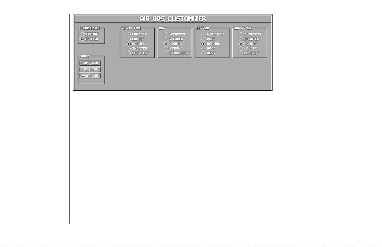
Air Ops
Four panels appear on
the Air Ops Customizer
screen: Ready Time, CAP
(Combat Air Patrol), Search
and CAP Range.
READY TIME: This panel controls theamountof time required to fuel and loadaircraft. The settings range from
LONGEST to SHORTEST.
CAP: Combat Air Patrol is made up of fighters whose mission is to interdict all enemy aircraft. The more
effective the CAP the fewer enemy planes can attack friendly ships and bases. This panel ranges from
WEAKEST, meaning less effective, to STRONGEST, being most effective.
SEARCH: In order to attack, the enemy must first be located. Searching values range fromVERY BAD to BEST.
CAP RANGE: This panel controls the distance from the base or ship that CAP aircraft can intercept enemy
planes, from SHORTEST to LONGEST.
14
M
ENUBAR:CONTROLSMENU
Page 19
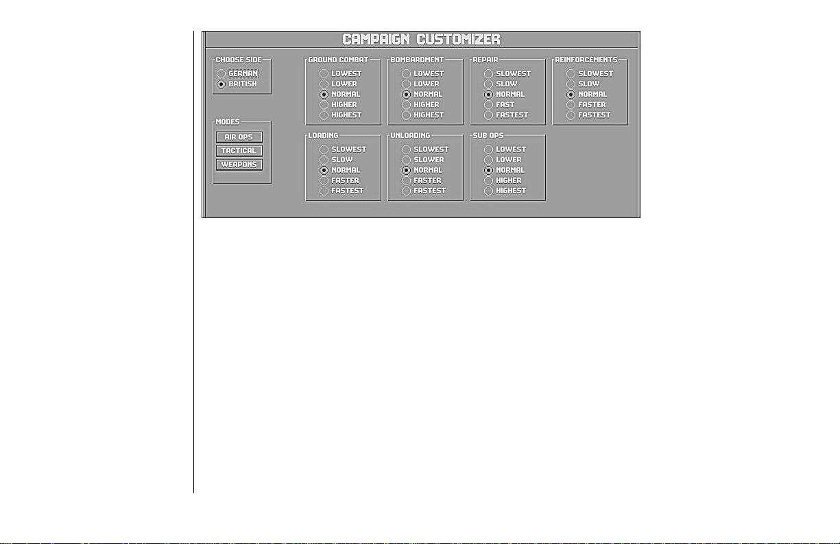
Campaign
The Campaign Customizer
screen has seven panels:
Ground Combat, Bombardment, Repair, Reinforcements, Loading, Unloading
and Sub Ops.
GROUND COMBAT: Settings on thispanelrange from LOWEST to HIGHESTindicatingthe effectiveness of all
non-naval, non-air forces.
BOMBARDMENT: This panel controls the damageandaccuracy of level bombers such as theB-17e and the
G3M3 Nell, as well as navalbombardment.The range is from LOWEST to HIGHEST.
REPAIR: Ships damaged during long scenarios may be repaired atarateranging from SLOWEST to FASTEST.
REINFORCEMENTS: This controls how quickly reinforcements become available during a scenario, from
SLOWEST to FASTEST.
LOADING: This controls how quickly troops and cargo are placed aboard ships, from SLOWEST toFASTEST.
UNLOADING: This setting controls how quickly troops and cargo exit ships, from SLOWEST to FASTEST.
SUB OPS: The effectiveness ofsubmarineinterceptions and attacks can beadjustedfrom LOWEST to HIGHEST.
15
M
ENUBAR:CONTROLSMENU
Page 20
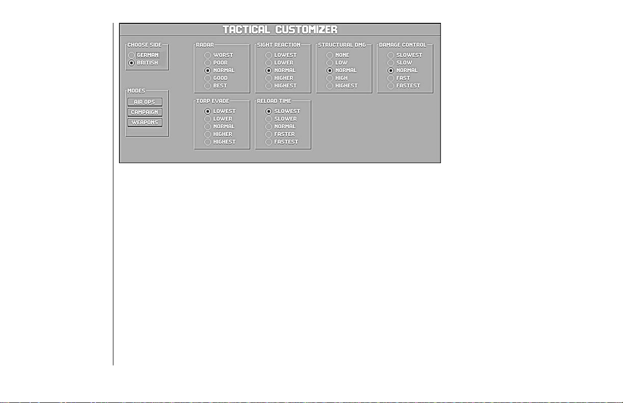
Tactical
On the Tactical Customizer
screen, six panels affect
aspects of surface engagements between ships: Radar,
Sight Reaction, Structural
Damage, Damage Control,
Torp Evade, and
Reload Time.
RADAR: These buttons adjustthe accuracy of radar forranging, rated from WORSTto BEST. Radar must be
present on a shipfor this setting to havean effect.
SIGHT REACTION: This setting controls the probability for visual spotting of enemy ships, planes, and torpedoes. The range is from LOWEST to HIGHEST.
STRUCTURAL DAMAGE: Repeated hits by enemy fire can weaken the structural integrity of a warship. This
control adjusts the severity of the effect of structural damage, ranging from NONE to HIGHEST.
DAMAGE CONTROL: The damage controlcrews’ability to repair damage incombatcan mean the difference
between victory and defeat. Thispanelcontrols the speed at whichthecrews work, from SLOWEST toFASTEST.
TORP EVADE: When incoming torpedoes have been spotted a ship turns into their path in order to minimize
the chance of impact. The effectiveness of this maneuver ranges from LOWEST to HIGHEST.
RELOAD TIME: Most crews were not trained to reload torpedoes in combat. For hypothetical games, crews
can be given the ability to do so by setting this control at any setting except SLOWEST.
16
M
ENUBAR:CONTROLSMENU
Page 21

View Control (Alt–I)
The view control window has two sets of radio buttons labeled Events and Target.
EVENTS: With the Events control on, the View panel on the Flagbridge, Ship bridge, and Air Ops stations
shows the first hit from gunfire, all torpedo hits, and the sinking of target vessels.
TARGET: With the Target control on, the View panel centers on the current target of the active ship.
S
TATIONSMENU
R
EPORTSMENU
The Stations pull-down menu allows movement between the screens where command of the task force or
vessel really happens. The options on this menu can also be selected using function keys F1 to F9. See the
section “Commanding Task Forces and Ships” on page 19 for more detailed information about each station.
This menu enables you to get a variety of summary reports. Left-click on an item in one of these reports to
get more details about it.
Statistics(Alt–F1)
This window shows the number of rounds fired from main and secondary batteries and the number of torpedoes fired. The number of hits and the percentage of hits from rounds fired is also indicated.
Victory (Alt–F2)
This window lists the ships, aircraft, and bases in thecurrentscenario,their status, and victory point value. Each
side’s list can be accessed by left-clicking on the flagorbuttonon the right side, and each side’s total victory points
are calculated at the bottom. At the end of thescenariothelevel of victory is shown on a bar above theCONTINUE
button. This shows a result based on damage inflicted, butnotcasualtiestaken, until the scenario is ended.
Visibility (Alt–F3)
Destroyers, cruisers, and battleshipshave observation towers of differentheights. The ranges atwhich the different sized ships canspot each of the othersizes of ships isshown here. If radar isin use, it isindicated as well.
Reinforcements(Alt–F4)
This window lists upcoming reinforcements if specified as part of the scenario.
17
M
ENUBAR:STATIONSMENU
Page 22

B
RIEFINGSMENU
This menu enables you to get background information on the naval vessels, aircraft, and naval and aerial
weapons systems in use in the Atlantic Theater.
Ships (Ctrl–F1)
This screen shows a waterline view of the selected ship in the top third and an overhead view in the lower
third. The center panel shows statistics pertinent to the class of vessel. The control bar at the very bottom
has buttons that control the selection of what is shown. The NEXT and PREVIOUS buttons cycle through the
list of vessels. The LIST button opens a window with a list of all the ships available to either side. The leftand
right arrow keys rotate the top view around the ship’s axis, while the “+” and “–” keys zoom the view in and
out. CHANGE SKY alters the apparent light level and changes the cloudscape.
Aircraft (Ctrl–F2)
This screen shows a side view of the aircraft at the top of the screen. The panel in the middle shows statistics
pertinent to the class of aircraft. The control bar at the very bottom of the screen has buttons that control the
selection of what is shown. The NEXT and PREVIOUS buttons cycle through the list of aircraft. The LIST
button opens a window with a list of all the aircraft available in the game. The left and right arrow keys rotate
the top view around the aircraft’s axis, while the “+” and “–” keys zoom the view in and out. CHANGE SKY
changes the cloudscape without altering the apparent light level.
Guns (Ctrl–F3)
This screen shows statistical data on the guns that were used during the period portrayed in the game, by the
Allied and Axis forces.
Torpedoes (Ctrl–F4)
This screen shows statistical data on the torpedoes that were used during the period portrayed in the game,
by the Allied and Axis forces.
18
M
ENUBAR:BRIEFINGSMENU
Page 23
COMMANDING
T ASKFORCES
AND SHIPS
Command of task forces or ships is managed through the use of several action stations aboard the flag ship
of a task force or from the bridge of a specific ship. These stations are selected by using the options from the
Stations menu or the function keys F1 through F9.
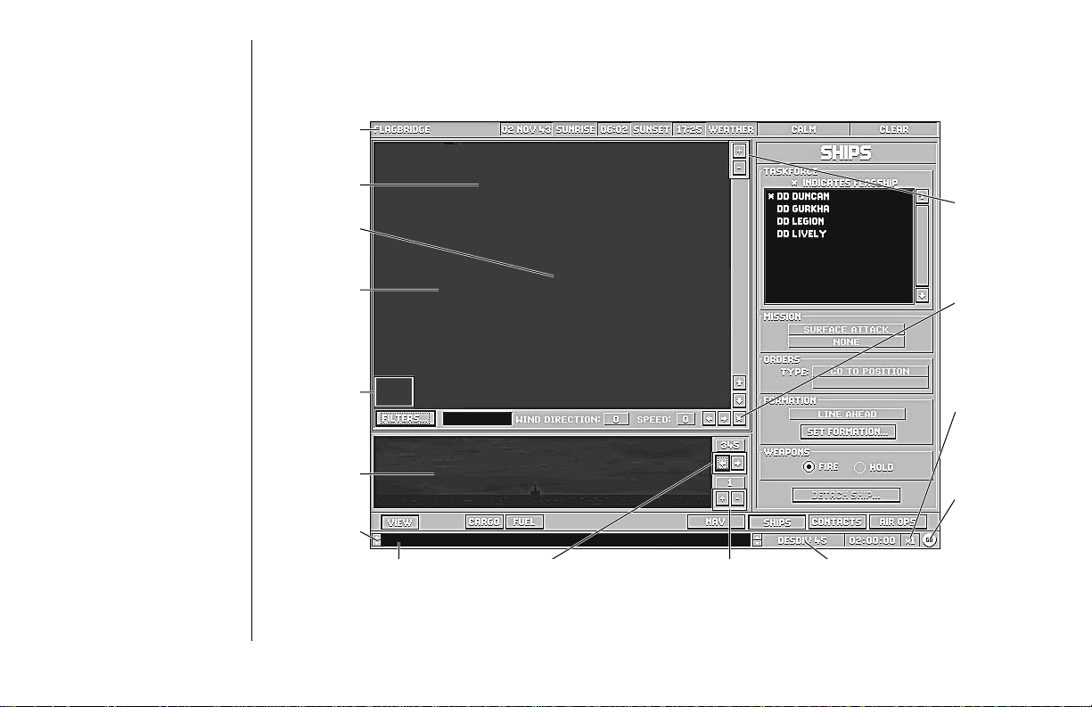
station
F
LAGBRIDGE
S
TATION
base
task force
map panel
map zoom
level
view panel
scroll buttons
message display
view bearing control
view zoom control
active task force
The Flagbridge is the first station you enter when you start a new engagement. TheFLAGBRIDGE station is
selected from the Stations pull-down menu or by pressing F1.
19
C
OMMANDINGTASKFORCES ANDSHIPS:FLAGBRIDGESTATION
map panel
zoom cotrols
center view
button
game speed
control
pause/resume
game
Page 24

MapPanel
The Map panel is displayed as part of the Flagbridge, Ship Bridge, and Air Operations stations. The maps
generally show similar information and use the same controls. There may be minor differences between
map displays due to features not being available on certain ships. The Map panel is both a visual reference
and a means of issuing certain commands. To help you keep track of the battle, it shows the locations of
your own ships, known enemy ships, aircraft, torpedoes, shell splashes, and other features of the battle.
Furthermore, there are a number of “filters” you can use to toggle the display of different kinds of useful
information. For more information, see the “Filters” section on page 22.
To facilitate input of orders, you can issue certain instructions by pointing and left-clicking directly on the
map, most notably picking a ship to give orders to, and designating targets.
MouseCommands on the MapPanel
To center the map at a given location, point at that location with the mouse pointer, then press the “Ctrl” key
and the left mouse button at the same time.
TF Symbols
When the map is zoomed out to the 100x75 resolution or above, it shows the location of task forces rather
than individual ships. The location of each task force (TF) is marked by a stylized rendering of a ship. If the
TF Names filter is on, the identification code of the TF commander is displayed next to the group; if not, the
name is displayed in the text box just below the map next to the FILTERS button whenever the cursor is
moved over the center of the group. If the TFs are very close together, they are displayed as a single TF icon.
Ship Symbols
At levels of zoom of 50x37 and below, the positions of individual ships are shownon the map. Ifthe TF Names
filter is on, the ship positions are marked by flags of the appropriate nationality. Ifnot, the ships’ positionsare
shown by top-down views of the ships themselves, colored blue for Allied ships and redfor Axis ships.
Active Ship / TF Indicator
A white square bracketing a shipsymbolindicates that this is the currently activeship. This is only true if themap
is being displayed at a shipactionstation, or if the currently active TFis being displayed at the Flagbridge station.
20
C
OMMANDINGTASKFORCES ANDSHIPS:FLAGBRIDGESTATION
Page 25

Target Ship Indicator
This small white square indicates the current target of the active ship.
AircraftSymbol
This shows the current location of an airplane or formation of airplanes at higher zoom levels.
Wind Direction
Shows the direction of the prevailing wind. This affects the movement of smoke screens as well as the accuracy of gunnery in high winds.
Wind Speed
Wind speed is an important factor in a battle, not only because it may preclude air operations, but also
because it can tell you where the weather is on the Beaufort Scale. Heavy seas can hinder visibility and the
accuracy of your weapons, and may even make certain actions impossible. For more information on the
Beaufort Scale and weather in general, see “The Environment” section on page 82.
Magnification Controls
The “–” button decreases the magnification of the map (shows a larger area in less detail), while the “+”
button increases the magnification (shows a smaller area in greater detail).
VerticalScrollButtons
These shift the area displayed on the map up and down (north and south).
HorizontalScroll Buttons
These shift the area displayed on the map left and right (west and east).
Center Button
When you click on the asterisk (*) in the lower right corner of the map frame, the map automatically centers
itself on the currently selected ship or task force.
Map T e xtDisplayBox
Information about the area within the cursor appears here. This is generally a ship, TF,aircraft, or base name.
21
C
OMMANDINGTASKFORCES ANDSHIPS:FLAGBRIDGESTATION
Page 26

Filters
The FILTERS button displays the Map Filters
window which enables you
to toggle the display of
certain kinds of information
on the map. The common
filters that can be displayed
on the map at any action
station are described first;
station-specific filters are
described afterwards.
Air Filters
AIR FORMATIONS: This
filter displays icons for air
groups on the map.
FORMATION NAMES:
This filter displays the aircraft type of each active
air group.
FORMATION ORDERS: This filter displays orders for each currently active air group.
FORMATION SEARCH: This filter shows your current search aircraft and their search patterns.
AIRCRAFT: This filter shows icons representing the positions of aircraft.
AIRCRAFT NAMES: This filter displays the names of aircraft next to the icons.
22
C
OMMANDINGTASKFORCES ANDSHIPS:FLAGBRIDGESTATION
Page 27

Ship Filters
FLAGS: This filter displays ships as Allied or Axis flags.
MAIN GUNS: This filter displays a circle showing the maximum range of the current ship’s main guns.
SHIP NAME: This filter displaysshipnames next to their icons.Atzoom level 20x15 and abovetheremay not be
enough room to display shipnames,so this option operates bestwhenused at zoom level 15x11andbelow.
ORDERS: This filter shows the directionofmovement for the selected ship or TFif operating on a plotted course.
SUNK: This filter displays an icon for each ship sunk during the current engagement.
TORPEDOES: This filter shows three circles indicating the range of torpedoes fired by the selected ship when
set at short, medium, or long range.
VISIBILITY: This filter displays three circles around each ship, and shows the maximum range at which a
large, medium, and small ship can be sighted. Carriers and battleships are considered large ships, cruisers
are medium ships, and destroyers are small ships.
Miscellaneous Filters
AUTOCENTER: This filter centers the map on the currently selected ship or TF.
BASE NAME: This filter displays the name of each base on the map. If it is off, you can still find thename of a
base by moving the cursor over that base on the map. The name is displayed in the Map Text Display Box.
TF NAMES: This filter displays the names of task forces when the map is at zoom level 100x75 or above.
CONTACTS: This filter shows the location of all recent enemy ship sightings.
GRID: This filter superimposes a gray grid on the map at zoom levels 100x75 and below. The distance
between the grid lines is 10,000 yards. At very low zoom levels you may not be able to see the grid lines
because the area depicted falls between two lines.
RANGE CIRCLES: This filter superimposes a series of circles on the map panel that show distances of 250,
500, and 750 miles from the active task force.
TF PLOT TIMES: Displays the time in minutes until the task force completes its current plotted movement.
23
C
OMMANDINGTASKFORCES ANDSHIPS:FLAGBRIDGESTATION
Page 28

Flagbridge Control Bar
The Flagbridge contains an additional control bar (just above the Message Bar) that contains six buttons.
These buttons are VIEW, CARGO, FUEL, NAV, SHIPS, CONTACTS, and AIR OPS.
View Panel
The View panel is located on the lower left side of the screen under the Map panel on the Flagbridge, Ship
Bridge and Air Operations stations. This display shows the area around the currently selected ship. The view
can be swung around the points of the compass in ten degree increments and zoomed in and out using the
controls to the right of the panel. The zoom levels of 1, 2, 3 and 4 are equivalent to the Lookout, Turret,and
Torpedo station zoom levels of 1, 2, 4, and 8.
Cargo Panel
You can view the Cargo panel from either the Flagbridge or the Ship Bridge station. It shows information
about the total capacity and current load of troops and supplies of the currently selected task force or ship.
Capacity
The total amount of troops and supplies that the task force or ship can carry.
Supplies
The total amount of supplies that the task force or ship currently carries.
Troops
The total amount of troops the task force or ship currently transports.
FuelPanel
Capacity
The total amount of fuel that the task force or ship can carry.
Remaining
The total amount of fuel that the task force or ship still has.
24
C
OMMANDINGTASKFORCES ANDSHIPS:FLAGBRIDGESTATION
Page 29
Usage
The amount of fuel the task force or ship consumes per hour under way.
Duration
The length of time that the task force or ship can continue under way with its current fuel supplies.
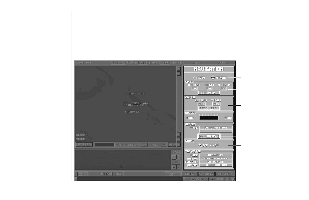
NavigationPanel
The navigation panel gives you control over the orders, speed, and direction of the selected task force.
Auto/Manual Buttons
task force speed control
course control
orders control
smoke screen control
25
C
OMMANDINGTASKFORCES ANDSHIPS:FLAGBRIDGESTATION
Page 30

Auto / Manual Buttons
These buttons set the station to Auto or Manual. The navigation controls are only enabled if the panel is set
to Manual.
Speed
Current
The vessel’s current speed in knots.
Target
The vessel’s desired speed in knots. If this is different than the current speed, it is because the ship is accelerating, decelerating, or is unable to reach the desired speed because of damage.
Maximum
The fastest speed in knots that the vessel can travel in its current condition. A task force can only travel as
fast as the slowest ship in the task force. Task forces move slightly slower than the slowest ship because they
must also maintain formation.
Set Speed
This button displays the Set Speed window in which you can set the Target speed for the vessel. The Current
and Maximum speeds are identical to those displayed on the main panel, but between them is an active box
in which you can set the target speed either by left-clicking on the up (faster) and down (slower) arrows to
the right, or by entering a number directly.
Press OK to enter the new speed, and CANCEL to exit without changing the original Target speed.
Course
The “SET COURSE. . .” button does not become active until the task force or ship’s orders have been
changed to Manual. See the description of Manual orders on page 27 in this section.
Current
The direction in degrees that the vessel is currently heading.
26
C
OMMANDINGTASKFORCES ANDSHIPS:FLAGBRIDGESTATION
Page 31

Target
The direction that the vessel has been set to sail. If this is different than the current direction, it is because
the ship is turning, or is unable to reach the desired course because of damage.
Rudder
This gauge shows the degree to which the ship’s rudder has been turned in order to swing to a new course.
Manual control of the ship’s course is achieved using the Manual orders option. See the description of
Manual orders below.
Orders
You can give a ship a wide variety of orders from the Navigation panel.
Type
The ship’s current orders.
Target (optional)
If the ship’s current orders involvenavigatingrelative to some other ship, this fielddisplays the name of that ship.
Set Orders
This button calls out the Set Orders window, which shows the different types of orders to assign the task
force or ship:
Manual: This button activates the “SET COURSE. . .” button on the COURSE control. Left-clicking on this
button displays the Set Heading window in which you can set the target course for the vessel. The current
heading is identical to the number displayed on the main panel, and it also appears as a grey line on the
compass. The active box beneath the compass is where you can set the target course either by left-clicking
on the up and down arrows to the right, or by entering a number directly. The target course appears on the
compass as a red arrow, and it can be also set by left-clicking directly on the compass itself.
Press OK to enter the new course, and CANCEL to exit without changing the original Target.
27
C
OMMANDINGTASKFORCES ANDSHIPS:FLAGBRIDGESTATION
Page 32

Tactical: Once a task force or ship has completed a plot, if their previous orders are interrupted, orif damage
prevents them from following orders, Tactical is the default setting.
Follow: When you choose this option and left-click OK, the Select Ship window opens andyou can select a
ship from the list of friendly vessels to be the target. Once you left-click OK again, the ship you are controlling maneuvers to get behind the target, and then endeavors to move at the same speed and maintain the
distance that you have selected.
Intercept: When you choose this option and click OK, the Select Shipwindow opens, and you can select a
ship from the list to be the target. Once you left-click OK again, the ship you are controlling moves toward
the closest point at which its path can cross that of the target. If the target changes course, the ship with this
order recalculates its course to reflect the new situation.
Patrol Box: This command is much like Follow Plot, except that you designate four points which form the
four corners of the box that the ship will move around.
Patrol Line: Like Patrol Box, except that the two points you designate are the twopoints the ship will
travel between.
Plot Course: When you choose this option and left-click OK, the Set Plot window appearsand the map
clears. You can use the cursor to enter up to ten way-points. Once you left-click OK on Set Plot, the ship
moves from its present position to the first way-point; from there to the second and so on, until it reaches
the last.
Return to Base: When you select this option and left-click on OK,the Select Base window appears. Double
left-click on a base name in the list and the computer plots a course for the ship to move there.
Shadow: This works like the Follow command, above, except that the Select Ship window contains a list of
enemy ships. When you select one, your ship maneuvers to take up station behind the target, and then
moves on the same course and at the same speed, at the distance you specified.
28
C
OMMANDINGTASKFORCES ANDSHIPS:FLAGBRIDGESTATION
Page 33

Torp Attack: When you select this option and left-click OK, the Select Ship window appears,containing a list
of enemy ships within sight of your ship. Double left-click on one to designate it as the target for the torpedo
attack, and your ship maneuvers into position and launches its weapons. If the button at the top of this
panel is set to AUTO, your torpedoes are automatically fired. If your ship is on MANUAL, you must left-click
on the FIRE button which is found on each individual torpedo mount. See the “Torp Button and Torpedo
Panel” section on page 41 for more information. This option is only available on the Ships Bridge station.
Smoke
This control enables youto have the currently selectedship lay a smokescreen. If you set itto ON, it trailsa
cloud of thick, oilysmoke that obscures vision acrossits track. Remember thatsmoke drifts in the directionthe
wind is blowing, andif the wind is strong,the smoke screen isineffective.Note: Smoke doesn’t actually appear
on the map panelor in the view panel,but the effect isaccounted for by the game’sartificial intelligence.
Task force
Name
The name of the task force that the ship is currently part of.
Mission
The purpose of the ship’s task force.
Flagship
The flagship of the ship’s task force.
Orders
The task force’s current orders.
29
C
OMMANDINGTASKFORCES ANDSHIPS:FLAGBRIDGESTATION
Page 34

formation
option
window
set
formation
button
detach
ship
button
Ships Panel
The Ships panel gives you both summary information and generalized control over the ships in the selected
task force. The Ships panel also allows you to select a particular ship to take command of, and changes to the
Bridge station of that ship. Note: Manual controlof individual ships is only possible after they have been
detached from a task force using the “DETACH SHIP. . .” button.
30
C
OMMANDINGTASKFORCES ANDSHIPS:FLAGBRIDGESTATION
Page 35

Task Force List
This list shows the name and type of each ship in the task force.
A Legend of Ship Types
BB: Battleship
CV: Aircraft Carrier
CVE: Escort Carrier
CVL: Light Carrier
CA: Heavy Cruiser
CS: Seaplane Carrier
CL: Light Cruiser
DD: Destroyer
TR: Transport
Direct Access to Ships
To detach a ship fromatask force, left-click on thatship’sname on the list. Onceaship is selected the “DETACH
SHIP. . .” button atthebottom of the panel becomesactive.Left-clicking on this button detachestheship,
making it available for independentaction;this is useful when shipsareheavily damaged or when ashipneeds
to be detached for amissionsuch as a torpedo attack.Oncea ship has been detacheditsname disappears from
the ship list. Refer tothe“Ship Bridge Station” section onpage35 for details on commandingindividualships.
Once detached, a ship cannotrejoina task force.
You can move directly to the Ship Bridge station of a ship in the currently selected task force by double leftclicking on its name in the list.
31
C
OMMANDINGTASKFORCES ANDSHIPS:FLAGBRIDGESTATION
Page 36

Flagship Indicator
The flagship of the task force is indicated by an asterisk (*) to the left of its name.
Large Task Forces and the List
If the task force contains more ships than can be shown in the list, the remainder are accessible by using the
scroll controls to the right of the list.
Mission Indicator
This area displays the mission of the currently selected task force. If playing a short scenario, this setting is
preset. During a longer scenario, you assign missions to the task forces you create.
Orders Indicator
This area displays the task force’s current orders, as set in the Flagship Bridge.
Formation Controls
This area displays the task force’s current formation. If playing a scenario, this setting is preset.
Formations
A task force’s formation definestherelative positions that the shipsattemptto maintain. Relative position isa
critical factor in battle becauseproperpositioning enables your ships tomaximizetheir effectiveness against the
enemy, while the wrong formationcanminimize their impact or makethemvulnerable to devastating attacks.
When setting formations, remember that the ships cannot magically appear in the positions you have
selected; it takes some time to move to the proper position.
32
C
OMMANDINGTASKFORCES ANDSHIPS:FLAGBRIDGESTATION
Page 37

The possible formations are:
CUSTOM: This option enables you to have the ships take any relative positions you desire. When you choose
it, you see a display with a task force list and a small map view showing the TFs’ current relative positions.
When you select a ship’s name from the list, it is highlighted by an orange box in the formation window.
When you left-click on the map, the ship’s icon moves to that location. Once you have positioned all the
ships where you want them to be, left-click on OK.
Note: If you want to spread theships out beyond the area currently displayed,youcan either scroll using the horizontal and vertical scroll bars, orzoomout by pressing the “–” control tothe upper right of the map. Similarly,if
you want to position two shipsmoreprecisely, you can increase the zoom levelby pressing the “+” button.
LINE AHEAD: The ships steam in a column, one following another, with the flagship in the middle. When
you select this option, you are given an opportunity to specify the distance between ships.
LINE ABREAST: The ships steam in a row, one beside another, with the flagship in the middle. When you
select this option, you are given an opportunity to specify the distance between ships.
AA DEFENSE: The ships form a tight, circular group with the destroyers on the outsidebut close to theheavier
ships to provide an all-around defense that maximizes the effects of the entire group’s anti-aircraftweapons.
Weapons Display and Fire Control
Fire: The ships in the task force fire at will.
Hold: The ships in the task force cannot fire.
Contacts Panel
The Contacts Panel lists all enemy forces that have been spotted by your forces. In general, just a contact I.D.
appears, but as the information becomes more accurate, a list of ship types or even names may be shown.
33
C
OMMANDINGTASKFORCES ANDSHIPS:FLAGBRIDGESTATION
Page 38

Time of Report
The time at which the contact was made.
Bearing
The direction of the contact from the current task force.
Heading
The direction the contact is moving.
Speed
The speed at which the contact is moving.
Range
The distance from this task force to the contact.
Ships Sighted
The classes of the ships sighted for that particular contact.
Air Ops Panel
The Air Ops panel gives you information about and generalized control over the air operations of the CAP
(Combat Air Patrol) and Search aircraft of the currently selected task force or air base.
Aircraft Window
This window shows a list of the types of aircraft available on the selected ship(s) or base. Below the list, the
status of the aircraft highlighted in the window appears on three lines:
ON DECK: The number of aircraft of the selected type that are ready for flight.
IN HANGAR: The number of aircraft remaining in the ship or base hangar.
READYING: The number of aircraft being readied for flight.
34
C
OMMANDINGTASKFORCES ANDSHIPS:FLAGBRIDGESTATION
Page 39

S
HIPBRIDGE
S
TATION
Formations Window
This window shows a list of the formations currently assigned missions. A formation can be as few as one
plane, and frequently is when search missions are assigned. If the formations on missions are more than can
be shown by the list, the remainder are accessible by using the scroll controls to the right of the list.
Below the list, the status of the formation highlighted in the window appears on five lines:
MISSIONS: The selected formation’s current mission.
PLANES: The number of planes in the selected formation.
HEADING: The selected formation’s heading.
RADIUS: The currently selected formation’s range in hours and minutes.
TARGET: The target of the selected formation. If the formation’s mission is Combat Air Patrol, the target is
the ship from which the aircraft were launched.
Combat Air Patrol
The “SET CAP. . .” button opens the window where the percentage of fighters available for Combat Air Patrol
(CAP) is set. Up to 100% of the fighters assigned to the task force can be used as CAP; however, only thefighters left over from CAP can be used to escort bombers.
If ships are detached from a task force, they are controlled from their own Bridgestations rather than fromthe
Flagbridge station. The VIEW, CARGO, and FUEL button operations are identical to those described onpage
24. The NAV button and Navigation panel operate identically to the Navigation panel described onpage 25.
The other four buttons on the control bar: AIR, DAM, GUN, and TORP, allow or deny access to panels
depending on which ship’s bridge is being viewed. For example, destroyers have a Torpedo panel, aircraft
carriers do not; conversely, aircraft carriers have an Air Operations panel, destroyers do not.
35
C
OMMANDINGTASKFORCES ANDSHIPS:SHIPBRIDGESTATION
Page 40

station
lead ship
course plot
active ship
flagship
gunnery
button
navigation
button
torpedo
button
air operations button
damage control button
Air Operations Button and Panel
The Air Ops panel gives you information about the air operations of the currently selected ship or base, such
as loading status and readying time. Toggling the Aircraft and Formation buttons displays information about
what planes are ready and what the mission status is for any formations. The bottom display shows the
Hangar Capacity, Launch Capacity and the number of Planes in Hangar.
36
C
OMMANDINGTASKFORCES ANDSHIPS:SHIPBRIDGESTATION
Page 41

compartment
status display
flood level
indicator
scuttle
control
Damage Button and Panel
The Damage (DAM) panel gives you information about the well-being of the currently selected ship, and the
ability to scuttle it (deliberately sink it to keep it from falling into enemy hands).
37
C
OMMANDINGTASKFORCES ANDSHIPS:SHIPBRIDGESTATION
Page 42

Auto / Manual Buttons
These buttons set the station to Auto or Manual. TheSCUTTLEbuttonis only enabled if the panel is set to Manual.
Compartments
This display shows you the total number of compartments the ship is divided into, and how many have been
damaged, destroyed, flooded, or are currently on fire. You can see more detail about exactly which compartments have been damaged in what way at the Damage Control Screen.
List
This display shows you how much the ship is listing to port or starboard, or forward and aft. If the needle of
either gauge is in the red area, your ship is in serious danger of capsizing.
Pumps
This display shows how many pumpsyouhave total and how many are available.The most obvious use for them
is to pump water out ofcompartments(“bailing”), but they can also be usedto pump water in to correct forlist
(“counterflooding”), as well as putting outfireson lower decks. To manage either bailingor counterflooding issue
orders from the Damage Control station.
Flood Level
This gauge shows you how deep in the water your ship is sitting, and thus how close it is to sinking. Ifthe
flood level is in the red zone, your ship is in real trouble. Keep your eye on this gauge, especially if youare
engaged in counterflooding.
DC Party Status
This display shows you how many Damage Control Parties you have in total and how many are available.
StructuralDamage
Percentage of structural damagethe ship has sustained. Seepage 73 for detailsof the effects on shipoperation.
Scuttle Button
The SCUTTLE button enables you to sink your own ship deliberately. It is generally used as a last resort to
keep the vessel from falling into enemy hands.
38
C
OMMANDINGTASKFORCES ANDSHIPS:SHIPBRIDGESTATION
Page 43

director
and turret
status
set target
buttons
fire/hold
control
Gun Button and Gunnery Panel
The Gunnery panel gives you information about your guns and some control over the guns on the currently
selected ship.
39
C
OMMANDINGTASKFORCES ANDSHIPS:SHIPBRIDGESTATION
Page 44

Auto / Manual Buttons
These set the station toAutoor Manual. The SET TARGETbuttonsare only enabled if thepanelis set to Manual.
AA Guns
This display shows thenumber of anti-aircraft guns onthe ship. They aredivided into four classes arranged
according to size, range,and weight of shot. Largerguns also have bettersighting and fire control mechanisms.
Directors
This display shows how many fire control directors your ship has, and whether they are currently damaged
or destroyed. Directors improve the accuracy of your main guns dramatically. The association between
directors and guns is not set: one director can control all turrets, or one can control the forward turrets while
the other controls the aft turrets.
Turrets
This display shows the number of active gun turrets your ship has (main and secondary), and how many
have been damaged or destroyed.
Ammo
This display shows the percentage of your ammunition you have left for all of your guns.
Target 1
This display shows the name, speed, course, and status of the primary (or only) target being tracked (if your
guns have been ordered to hold fire) or engaged by your main guns.
40
C
OMMANDINGTASKFORCES ANDSHIPS:SHIPBRIDGESTATION
Page 45

Set Target 1 Button
You can set or modify this setting by pressing the SET TARGET 1 button. This calls out the Select Ship
window which lists all enemy ships within range. Double left-click on the one you want to target, or cancel
to exit without changing the current setting.
Target 2
This display shows the name, speed, course, and status of the alternate target (if any). Your ship willnot split
its fire between this target and the primary target unless it cannot engage the primary target with some of its
guns. Normally, it deals with the primary target first with all guns, then switches to the secondary target.
Set Target 2 Button
This button works the same way as the SET TARGET 1 button.
Fire/ Hold Buttons
This orders the guns to fire when ready or hold fire (while tracking their targets). It is especially useful during
night engagements when you may want to have your guns ready to fire as targets present themselves.
NavButton and Navigation Panel
When commanding a single ship, the Ship Bridge station Navigation panel operates identically to Flagbridge
panel. See the “Navigation Panel” section on page 25 for more information.
Torp Button and TorpedoPanel
If a ship is equipped with torpedo tubes, moving the cursor over the TORP button and left-clicking activates
a panel which shows information about the ship’s torpedo mounts. Torpedo tubes on surface ships are generally mounted in groups that are operated together, so the information displayed is given for mounts.
41
C
OMMANDINGTASKFORCES ANDSHIPS:SHIPBRIDGESTATION
Page 46

Auto / Manual Buttons
These set the station to Auto or Manual.Note: If the button is set to Manual, torpedoes canonly be fired
manually from the torpedo mount.
Mount1
Tubes
The number of torpedo tubes on this mount.
Status
Whether the mount is fully operational (normal), damaged, or destroyed.
Loaded
The number of tubes that currently have torpedoes in them, ready to fire. This count decreases when one or
more tubes are fired.
Reloads
This is the number of additional torpedoes available to the tubes in the mount to replace fired torpedoes.
After a tube fires, the crew of the torpedo mount will reload it if a reload is available, but since torpedoes are
large, clumsy objects to manhandle on a heaving deck in the midst of battle, do not expect this reload
process to be quick.
Mount2orMore
If the vessel has more than one torpedo mount (most have either 2 or 4), information appears (in descending
order) for each additional mount.
42
C
OMMANDINGTASKFORCES ANDSHIPS:SHIPBRIDGESTATION
Page 47

M
AINGUNNERY
C
ONTROL
S
TATION
Gunnery Basics
Hitting a target at a range of up to twenty miles is not a trivial task, and requires some understanding of how
gunnery works. Basically, the gunnery director staff makes its best guess (fire control solution) of where to
aim from the bearing of the target, the range indicated by the range-finding equipment (optical and, if available, radar), and observation of the target’s course and speed. The guns then fire spotting rounds, whose
splashes are observed and used to make corrections before firing again. This process continues until the
splashes “bracket” the target, which means some are in front of it, while others are behind it. Once this has
been achieved, the guns can switch to full fire, although a return to spotting fire may be necessary occasionally as the target moves away from the bracketed position.
At long range, even an accurate fire control solution may only yield a few hits. There are many factors affecting accuracy: the sheer range (the longer the range, the more impact even small inaccuracies make), time in
flight (it takes a full minute for a shell to travel 30,000 yards, during which time the target has moved), the
size, speed, and maneuverability of the target ship, the amount of time the target has been tracked, waves,
wind, weather, light conditions, the quality of the firing ship’s crew, range finding equipment and guns,
whether or not the firing ship is itself under fire, and the number of ships firing at the target (more than one
makes it hard to keep track of spotting rounds).
To maximize your chances of hitting the enemy from this station, remember to use the maximum number of
guns you can (broadside if possible), use the spotting fire option initially, and then decide between a normal,
wide, or narrow spread when you go to full fire. Also, remember to fire the right kind of ammunition: star
shell to improve range finding during night combat, armor-piercing against battleships, and high-explosive
against almost everything else.
43
C
OMMANDINGTASKFORCES ANDSHIPS:MAINGUNNERYCONTROLSTATION
Page 48

target bearing indicator director lights ammo selector fire pattern control knobs
target
quality
guage
target
name
turret
icon
target
name
delay
counter
turret
light
readiness
indicator
range
readout
DirectorControl Layout
The Gunnery Control stations, both Main and Secondary, are divided into four horizontal areas in addition
to the standard Message Bar at the bottom of the screen: the Overhead view, the Alternate Director controls,
the Turret Status Display, and along the top the Main Director controls. For the Secondary Gunnery stations
on Battleships and Cruisers, the directors control Port and Starboard turrets.
44
C
OMMANDINGTASKFORCES ANDSHIPS:MAINGUNNERYCONTROLSTATION
Page 49

Overhead View
The Overhead View shows a bird’s-eye view of the active ship. It is used mainly for illustrative purposes,
showing the orientation and firing of the main and secondary guns and torpedo tubes and graphic evidence
of the damage sustained by the ship.
Gunnery Controls
Main and Alternate Directors
The controls associated with the Main and Alternate Directors are identical. This reflects the fact that the two
directors have a fluid relationship to each other and to the guns.
The Alternate Director exists primarily as a redundant system. The instruments used by the directors are
sensitive; they play a crucial role in determining the ship’s effectiveness in battle, and it simply makes sense
to avoid a situation in which one lucky hit destroys a mighty warship.
This said, the alternate director can play a more dynamic role while the main one is still active. It enables the
ship to split its fire effectively, taking on more than one enemy at a time. While captains generally avoid this
approach (it is considered more effective to take out one enemy entirely than to pick away at two), there are
times when it is necessary.
This fluid relationship can exist because the relationship between the directors and the gun turrets is also
fluid. Either director can control any turret or set of turrets, and turrets can operate independently as well.
Because of the greater effectiveness of the directors’ sighting and range-finding equipment, “local control” is
generally reserved for when both directors are out, but its existence highlights the fact that you have considerable leeway about how your ships’ guns are controlled.
Because of the redundancy between the two control sets they will both be discussed together, with a special
section indicating how they can be coordinated and control of turrets transferred between them.
45
C
OMMANDINGTASKFORCES ANDSHIPS:MAINGUNNERYCONTROLSTATION
Page 50

TQ Gauge
This is the dial gauge at the left end of each Director Control area. The “Target Quality” (TQ) indicates the
degree of certainty of the fire control solution on the target. The higher the value, the more likely that the
next salvo will hit home.
Target Bearing Indicator
The compass dial just to the right of the TQ Gauge indicates the bearing of the target (in landlubber terms,
the direction of fire).
Target Name
The display below the Target Bearing Indicator gives the name of the enemy vessel at which that director’s
battery is firing. If the name is unknown, the display reads “Ship Ø.”
Turret Lights
The row of green lights along the upper center portion of the Director Controls is used to indicate which of
the ship’s turrets are currently controlled by this director. The numbers correspond to the numbers in the
Turret Status Display, and if the light is on, that turret is under that director’s control.
Man / Auto Switch
This switch sets whether the director can be controlled by the other controls at this director’s station. If it is
set to Manual, then the cursor switches from an arrow to a cross-hair whenever it is positioned over a place
that a control can be set to.
Range
This display, just to the right of the “Man/Auto” switch, shows the current estimate of the range to the
target vessel.
46
C
OMMANDINGTASKFORCES ANDSHIPS:MAINGUNNERYCONTROLSTATION
Page 51

Track Time
This display, just below the Range readout, shows how long the target vessel has been under observation in
order to obtain a fire control solution. The longer the track time, the more accurate the firing solution is.
Ammo Type Selector
This knob is to the right of the Range and Track Time readouts, and is used to determine what type of shells
the director’s battery fires. The three possible settings are: HE, AP, SS.
HE: High Explosive — generally used against lightly or unarmored targets, or by a lighter vessel against a
heavier one to damage its superstructure.
AP: Armor Piercing — generally reserved for use against heavily armored ships by other, equally heavy ships
(battleship vs. battleship for example).
SS: Star Shell — illumination rounds play a critical role in night battles.
Fire Pattern Control Knob
This knob, located to the right of the Ammo Type Selector, sets the specific fall of shot desired.
FULL: The normal pattern used once the target has been acquired. All guns in the active battery fire, and
continue firing as rapidly as they can be reloaded, with a normal spacing of shells falling on the target.
LOOSE: A pattern used when a hit is needed as soon as possible. The gun tubes are angled so that the shells
fall over a larger area than normal, which increases the probability of a hit on an imperfectly acquired target.
Because the shot pattern is so large, however, the chance of multiple hits is sharply reduced.
NRRW: Narrow, a pattern used when multiple hits are desired. The gun tubes are angled so that the shells
fall over a smaller area than normal, which increases the probability of multiple hits. The chance of a total
miss increases as well, and so is best used against a solidly acquired target.
SPOT: The normal pattern used when first firing on a target. The guns only fire a second time after their
splashes have been observed and their aim corrected.
HOLD: The battery remainstrained on the current target,but will not fireuntil a firing pattern isselected.
47
C
OMMANDINGTASKFORCES ANDSHIPS:MAINGUNNERYCONTROLSTATION
Page 52

Main / Alt Dir
These two lights show whether the director has been damaged or destroyed.
DAM: The director has been damaged.
DEST: The director has been destroyed.
Fwd / Aft Mag
These lights show the damage status of the corresponding magazine.
FIRE: The magazine is on fire. As the severity of the fire increases, there is a greater chance of the magazine
exploding — which is likely to destroy the ship.
FLOODED: The magazine is flooded. The ship’s rate of fire may decrease due to a lack of ammo.
DAM: The magazine has been damaged. Your rate of fire is likely to drop or even stop.
DEST: The magazine has been destroyed. Thank your lucky stars you’re still around to read about it!
Rounds
These readouts show the amount of ammo of each type in the magazine identified in the display just to the
left. For the meaning of the abbreviations, see the “Ammo Type Selector” section on page 47.
Turret Status Display
The turret status display isthearea between the two directorcontrolareas. It contains a numberofsimilar
display areas, each of whichcorrespondsto one of the ship’smaingun turrets. Their layout correspondsroughly
to their actual positions ontheship (i.e., the leftmost oneisthe furthest forward turret; therightmostone the furthest aft turret; side-mounted turretsareplaced above (for starboard) andbelow(for port) the centerline.
48
C
OMMANDINGTASKFORCES ANDSHIPS:MAINGUNNERYCONTROLSTATION
Page 53

Turret Number Light
The green light in the upper corner of each box contains the ID number of the turret. When it is lit, theturret
is active. If it is dark, that turret is damaged or destroyed.
Target Readout
The text area in the center of the turret box shows the name of the current target of that turret’s guns, ifone
has been acquired.
Readiness Status
The text area in the lower left of the box shows if the guns are ready to fire. If the turret isnot controlled
by a director there is no text in this area, even if it is undamaged. The different types of status are READY,
TURN, and LOAD.
READY: The turret’s guns are ready to fire. You will not see this often, except as it flashes by, unless you’ve
instructed the guns to hold their fire.
TURN: The turret is turning to aim at a target.
LOAD: The guns are being loaded. You see this message most frequently.
Delay Countdown
The numeric readout in the lower right of each Turret box shows the amount of time that the turret needs to
turn or load before it is ready to fire again.
Turret Icon
The icon in the upper-left of each Turret Display box shows the number of guns in the turret. When you
move the cursor over it, it lights up, and if you left-click the view changes to the Turret Control station.
49
C
OMMANDINGTASKFORCES ANDSHIPS:MAINGUNNERYCONTROLSTATION
Page 54

view
bearing
indicator
target
bearing
indicator
target
quality
guage
magnification
control
manual/
auto
switch
view left
control
view right
control
cursor
fire/hold controlammo selectordelay countertime-on-target indicator
Individual T urr etControls
This screen enables you to control each turret directly. Many of the controls are similar to those found at
the director, but only affect the guns in this turret, and through the gunner’s binocular you can have an
unmatched view of the battle. Note: You cannotget to this station via the pull-down menus; you must
access it via the Main Gunnery Control station.
50
C
OMMANDINGTASKFORCES ANDSHIPS:MAINGUNNERYCONTROLSTATION
Page 55

Turret ID
At the top center of the screen the turret is identified as Turret #. The number (#) corresponds to the ID
number found in the green light on the director. See the “Main Gunnery Control” section on page 43 for
details of the operation of the TQ Gauge, Compass Dial, Ammo Selector and Delay Readout.
View Bearing Indicator
The 360 degree gauge just below the turret ID indicates the direction in which the binoculars are pointed.
Magnification Control
This control, found to the right and below the binocular view itself, can increase and decrease the level of
magnification. If you put the cursor over the top half of the icon, it becomes a set of up arrows, and each
time you left-click, objects in the binoculars appear larger, while decreasing the field of vision. If you place
the mouse cursor over the lower half of the control, it becomes a set of down arrows, and when you left-click,
objects appear smaller, while the field of vision increases.
Magnification Level Readout
To the left and below the magnification thumb control is a digital readout that gives the level of magnification currently being displayed. In all, there are four levels of magnification: 1 (objects appear their actual
size), 2 (objects appear double size), 4 (four times actual size), and 8 (eight times actual size).
View Left and View Right Controls
If you place thecursor over the handles oneither side of thedirector, it becomes a setof arrows pointing tothe
closest edge of thescreen. If you left-click, theview in the binocularswings in that direction, andif you hold the
button down the viewcontinues to swing automatically. Youcan swing the viewthrough a full 360 degreearc.
Note: These controls only work if the SCOPE/LOCK switch is set to Scope. Otherwise, the view remains
locked on the current target (hence the label, Lock).
Scope / Lock Switch
This button, the leftmost of thethree“light switches” below the binocular view, locksthe view on the designated
target when set to Lock. Whensetto Scope it allows you to swingthe binocular view throughout a 360 degreearc.
51
C
OMMANDINGTASKFORCES ANDSHIPS:MAINGUNNERYCONTROLSTATION
Page 56

Fire/ Hold Switch
The center “light switch” below thebinocularview lets you instruct gun crews tohold their fire or fire when ready.
Man / Auto Switch
This switch must be set to Manual in order for any of the other controls at this station to work.
TQ Gauge
Like the TQ gauge at theMainGunnery Control station, this shows the reliabilityof the fire control range solution.
Compass Dial
Like the Compass Dial at the Director control, this shows the bearing of the current target.
Ammo Selector
Like the Ammo Selector at theDirectorcontrol, this lets you choose the typeof shells that the guns at thisturret
fire. For pros and cons ofeachtype, refer to the Direction section. Unlikethe display at the director, however, the
control here includes the ammo suppliesavailableto the turret in the digital readoutto the right of each setting.
Readiness Status and Delay Countdown
Like the Readiness Status Display and the Delay Readout at the Director control, these inform you of what
the gun crews are doing and how long before the guns are ready to fire.
Damage Indicators
The Dam (Damage) lights light up when the turret is damaged. The status reflects battle conditions; a turret
is considered damaged if it may be returned to functionality before the end of the current engagement.
When the turret is destroyed, you see a graphic representation of the destroyed turret controls.
TOT-Time on Target
TOT stands for Time on Target, or time remaining until shells in the air hit their target. Three numbers can
be displayed, showing the time remaining for the last three sets of shells. Because of the physics involved,
guns never have more than three sets of shells in the air at a time.
52
C
OMMANDINGTASKFORCES ANDSHIPS:MAINGUNNERYCONTROLSTATION
Page 57

S
ECONDARY
G
UNNERY
C
ONTROL
This station is very similar to the Main Gunnery Control station. It is used to direct the secondary armament
of battleships, with the main differences being that the turrets are identified by letters (A, B, C, etc.), and the
magazine information is for the starboard and port secondary magazines rather than the fore and aft main
magazines. For information about how the controls at this station work, see the “Overhead View” and
“Turret Status Display” sections on pages 45 and 48, respectively.
T
ORPEDO
S
TATION
This station contains the instruments that control a ship’s torpedo tubes. You can access it by selecting the
Torpedo option from theSTATIONS pull-down menu or by pressing F5.Note: that not all ships have torpedoes.
Torpedo Basics
The Torpedo Control Area contains the instruments with which you control the ship’s torpedo tubes.
Torpedoes are very powerful weapons, delivering a massive charge below the target’s waterline, but many
factors affect their targeting and therefore make them more difficult to use effectively. Fortunately, you have
analog computers available to help you make the necessary calculations. To launch torpedoes, you first want
to get as close to the target as you can, taking into account the eighty seconds required for a torpedo to arm
itself. At short range, high speed settings are much more accurate than the longer ones. Next, make sure that
the tubes on the target’s side of your ship are active (big ships had two sets of tubes, one per side). Selecta
target by switching the mount to Manual, left-click on the bar below the COMPUTE button, and pick one of
the ships listed in the window that appears. Set the spread to reflect your confidence in your aim, check the
computer’s suggested angle of fire (it should not be toward the enemy, because if you fire at him, he may be
gone when the “fish” arrives), make any corrections you think anticipate the target’s probable maneuvers (he
may turn toward you once he sees the torpedo coming), and then fire. It is a somewhat complicated business, one you will probably have to practice before you get it right.
53
C
OMMANDINGTASKFORCES ANDSHIPS:SECONDARYGUNNERYCONTROL
Page 58

view
bearing
indicator
magnification
control
54
target
selector
target
firing arc
view
bearing
controls
mount
selector
controls
target, speed,
range and
heading indicators
C
OMMANDINGTASKFORCES ANDSHIPS:TORPEDOSTATION
torpedo
speed/range
selector
torpedo
spread
selector
torpedo
activation
switches
torpedo
ready
lights
mount
selector
control
fire
button
Page 59

View Bearing Indicator
The 360 degree gaugejust below the binocular viewindicates the direction inwhich the binoculars are pointed.
MagnificationThumb Control
This control, found to the right of the binocular view itself, can increase and decrease the level of magnification. If you put the cursor over the top half of the icon, it becomes a set of up arrows, and eachtime you
left-click objects in the binoculars appear larger while decreasing the field of vision. If you place the mouse
cursor over the lower half of the control, it becomes a set of down arrows, and when you left-click, objects
appear smaller while the field of vision increases.
MagnificationLevel Readout
To the left and below the Magnification Thumb control is a digital readout that gives the level of magnification currently being displayed. In all, there are four levels of magnification: 1 (objects appear their actual
size), 2 (objects appear double size), 4 (doubled again), and 8 (doubled once more).
MountSelection Controls
When you place thecursor over the handles oneither side of thetorpedo director, it becomes aset of arrows
pointing to the closestedge of the screen. Whenyou left-click on theright control, you jump tocontrol of the
next torpedo mount (inascending numerical order, with a“wrap-around” to the firstwhen you use this control
on the highest-numbered one.Conversely, when you left-click onthe left control, youjump to the next mount
in descending numerical order,with a “wrap-around” from number1 to the highest-numberedmount.
Compass Dial
The compass dial at the torpedo station shows the heading of your ship through theship icon in thecenter.
The red area to the port or starboard of the ship icon indicates the arcof fire of thecurrent torpedo mount,
and the white line shows the exact direction within that arc that it is pointing.The white line alsoindicates the
firing line of the torpedo. You may manually control the firing angle of the torpedoesby adjusting the white
line within the display. The view at the top of the mount changes as thewhite line moves. Thered mark on the
outside of the compass dial shows the bearing of the selected target, or points northif no targets areselected.
55
C
OMMANDINGTASKFORCES ANDSHIPS:TORPEDOSTATION
Page 60

Auto / Manual Switch
This switch sets whether the director can be controlled manually by the other controls at this director’s
station. If it is set to Man (Manual), the cursor switches from an arrow to a cross-hair whenever it is positioned over a control whose selection can be changed.
Reload Readouts
The shorter of these two readouts shows the number of reloads available to this mount. The time readout
shows the countdown of time to reload a single torpedo tube. Torpedo tubes take eighty minutes to reload
on the standard setting. Changes made using the Customizer may increase or decrease this time.
Target Readout Control
The text area below the COMPUTE button shows the target ship for which a solution is currently being computed. Left-clicking on this area opens the Select Ship window which displays the list of potential targets.
Choose one of these by left-clicking on it.
If you left-click on this area and one or more enemy ships are potential targets, the Select Ship window
appears, and a target may be selected from the list by double left-clicking on it.
Left-clicking on the COMPUTE button calculates the computer’s best solution as to where the targeted ship
will be, assuming no changes in course or speed. Note: The compute button does not function at game
speed settings of x3 or x4.
Torpedo Activation Switches
A mount has between two and five switches depending on the number of tubes present in the mount. Each
switch makes one torpedo ready for launch when switched to the on (up, red) position. Only active torpedoes are launched when you press the fire button. Note: All torpedoes are active by default. Deactivating
some tubes allows you to reserve some torpedoes in the mount to be fired later in the battle.
56
C
OMMANDINGTASKFORCES ANDSHIPS:TORPEDOSTATION
Page 61

Torpedo Ready Lights
These lights show whether the corresponding torpedo is loaded and ready for activation. When the lights are
bright green, the torpedoes are ready to fire.
FireButton
This button launches all of this station’s activated torpedoes when it is left-clicked.
Spread
This button sets the distance between the torpedoes as they move toward the target. Possible spreads are:
NORM: Normal distance between torpedoes.
NRRW: Less distance than normal between the torpedoes. Used when aim is particularly reliable, or need for
multiple hits is great.
WIDE: More distance than normal between torpedoes. Used when aim is particularly uncertain, or against
multiple ships with overlapping profiles.
Torp Set Knob
This control shows, and enablesyouto set, the range andspeedof active torpedoes. The computer’schoiceis set
initially, but you can choosefromamong the possible settings foryourselfby left-clicking on the knobsettings.
SHORT: The torpedoes are set to run at maximum speed for a short distance. This setting gives the greatest
probability of a hit.
MEDIUM: The torpedoes are set to run at a somewhat slower speed for a somewhat greater distance. This
setting gives a somewhat lower probability of a hit.
LONG: The torpedoes are set to run at a slow speed for a long distance. This setting gives little likelihood
of a hit. This setting should be used only when firing at nearly stationary targets.
57
C
OMMANDINGTASKFORCES ANDSHIPS:TORPEDOSTATION
Page 62

Torpedo Range Readout
The Range (RNG) number to the right of the Torp Set knob is the maximum distance the torpedoes can run
at the current setting.
SpeedReadout
This is the speed at which the torpedoes run at the current setting.
FireAngle Readout and Controls
The Fire Angle readout (FA) shows the bearing at which the active tubes are pointed. To point them more
to the left, left-click on the black knob to the left; to point them more to the right, left-click on the buttonto
the right. The bearing can be changed more quicly by left-clicking directly on the compass dial. The tubes
should not be aimed directly at the target unless the target is stationary, since torpedoes move quite slowly
relative to the movement of the ships. Instead, they should point to the probable intercept point, the point at
which the torpedo will meet the target if it continues its present course and speed.
Target Speed Readout
This is the computer’s estimate of the target’s speed.
Target Range Readout
This display is under the legend RNG. The number shown is your crew’s estimate of the range to the target at
the projected fire angle.
Target Heading
This display is under thelegendHDG. The number shown isyourcrew’s estimate of the target’scurrentheading.
Damage Indicators
Dam: The damage lights light up when the mount is damaged if it can be repaired before the end of the
current engagement.
Dest: When the mount is destroyed, a graphic representation of the destroyed mount is shown.
58
C
OMMANDINGTASKFORCES ANDSHIPS:TORPEDOSTATION
Page 63

AIRO
PERATIONS
S
TATION
This station contains the instruments that control a ship’s aircraft.Accessitby selecting theAirOpsoptionfrom the
Stations pull-down menu or pressing F6.Note: Many cruisers and most battleships carry scout aircraft, while destroy-
ers don’t. Aircraft carriers, of course, have many aircraft, includingdivebombers,torpedo bombers, and fighters.
flight crew
activity
display
planes
available
capacity
panel
cutton
Air Operations Control Bar
The Air Operations station contains an additional control bar just above the Message Bar that has two
buttons, CAPACITY and VIEW.
59
C
OMMANDINGTASKFORCES ANDSHIPS:AIROPERATIONSSTATION
Page 64

View Button
This button returns to the view panel and controls. See the “Flagbridge Control Bar” section on page 24 for
information about this panel.
Capacity Button
This button displays the Capacity panel; it shows three pieces of information:
Hangar Capacity
This number is the total number of planes of all types that the ship can have on it.
Launch Capacity
This number is the total number of planes of all types that the ship can have ready to launch at a time.
Planes in Hangar
This number is the total number of planes of all types that are currently in the ship’s hangar area.
Summary Panel
The Summary panel contains five buttons which control how aircraft are prepared for flight and what missions they are assigned to. There are two buttons, Aircraft and Formations, above the list of aircraft available,
and three buttons labeled READY, UNREADY, and LAUNCH.
OperationsIndicator
Type
What hangar deck air crews are doing at the moment is indicated here. When you ready a number of planes,
the air crews would then start fueling, arming, and readying the planes for launch. Remember, the most vulnerable time on a aircraft carrier is when you have armed planes on your carrier deck.
60
C
OMMANDINGTASKFORCES ANDSHIPS:AIROPERATIONSSTATION
Page 65

Ready Time
If the current type of operation involves a delay (like “ready”), the amount of time remaining until it is completed is displayed here.Note: It takes about thirty minutes forplanes in the hangar to be readied.
Aircraft/ Formation Buttons
These buttons determine whether the controls affect individual aircraft or groups of aircraft.
Aircraft / Formation List
This text list area shows the types of the ship’s aircraft or the identities of its air formations. Whichever is
highlighted in yellow has information (and in the case of aircraft types, a picture) displayed below.
Aircraft Information
Mission
The activity which the aircraft type or formation has been ordered to do. For a list of possible missions, see
the “Mission Selector” section on page 63 for more information.
On Deck
The number of planes of this type that are on the flight deck or catapults, ready to launch.
In Hangar
The number of planes of this type that are in the hangar area.
Fueling/ Unloading
The number of planes of this type that are preparing for launch or standing down from launch-ready status.
61
C
OMMANDINGTASKFORCES ANDSHIPS:AIROPERATIONSSTATION
Page 66

FormationInformation
Mission
The activity which the aircraft type or formation has been ordered to do. For a list of possible missions, see
the “Mission Selector” section on page 63 for more information.
Planes
The number of planes in the formation.
Heading
The direction the formation is heading.
Radius
The maximum time the formation can remain in the air.
Target
The task force, air formation, or base the planes have been assigned to attack.
Ready Button and Ready Aircraft Window
Left-clicking on the READY button opens the Ready Aircraft window.
AircraftList
This list contains the classes of planes that are on the ship. The highlighted type is the one for which information appears to the right.
In Hangar
The number of planes in the hangar that are available to be readied.
62
C
OMMANDINGTASKFORCES ANDSHIPS:AIROPERATIONSSTATION
Page 67

Capacity
The maximum number of planes that may be readied.
Ready
This control enables you to set the number of planes of the highlighted type in the hangar to be readied.
Press the up arrow to increase the number; the down arrow to decrease it; or simply type in a number less
than or equal to the number in the hangar.
Mission Selector
This control enables you to set the purpose for which the planes are being readied. This decision is crucial,
for a plane well-prepared for one mission may be totally unprepared for another. For example, dive bombers
readied for scouting have more fuel and no bombs, which make them useless should enemy ships suddenly
appear nearby!
IMPORTANT NOTE: Once you set the mission for a type of plane, it appliesto all planes of that type on that
ship, even if you do not assign all available planes to be readied at this time. Thus, for example, you cannot
have half your dive bombers prepare for a land strike while the other half prepares for an attack on ships:
they all must prepare for one or the other. There is no substitute for planning ahead!
Missions that All Aircraft Can Undertake
Transfer: The planes carry no heavy ordinance and much fuel, so they have the longest possible range but
little effectiveness in combat.
Search (all except Fighter): Like transfer, but the planes are slightly more encumbered so that they cannot
travel as far but are somewhat more effective if they encounter enemy planes.
Fighter Missions
Fighter: The planes seek air-to-air combat with enemy aircraft, either to protect friendly strike aircraft, to
attack enemy strike aircraft, or to destroy fighters escorting enemy strike aircraft or protecting enemy ships.
63
C
OMMANDINGTASKFORCES ANDSHIPS:AIROPERATIONSSTATION
Page 68

Dive Bomber Missions
Dive Bomb Ship: The planes are armed with armor-piercing bombs designed to penetrate the protective
armor of major warships.
Dive Bomb Land: The planes are armed with high-explosive bombs designed to cause maximum damage to
enemy assets on the ground.
Torpedo Bomber Missions
Torpedo Bomb: The planes are armed with air-launched torpedoes for use against enemy vessels.
Level Bomber Missions
Level Bomb Ship: The planes are armed with armor-piercing bombs designed to penetrate the protective
armor of major warships.
Level Bomb Land: The planes are armed with high-explosive bombs designed to cause maximum damage to
enemy assets on the ground. Note: These planescan only be launched from bases.
Radius
The farthest point to which the planes can travel in order to carry out their mission. This range may be
affected by weather conditions or by the TF moving farther away.
Ordnance
The type of bombs or torpedoes the planes carry in order to carry out their mission.
OK Button
Left-click this button to indicate that you have finished selecting aircraft to ready.Note: You can, and usually
should, ready all the types of aircraft that you want to have ready. The reason for this is that once you start
readying aircraft, more aircraft cannot be readied until the first group has finished (which takes 30 minutes)!
Left-clicking OK when you have not selected all of each type you want to get ready means inconvenience at
best and disaster at worst.
64
C
OMMANDINGTASKFORCES ANDSHIPS:AIROPERATIONSSTATION
Page 69

Cancel Button
Left-click this button to exit the Ready Aircraft window without readying any aircraft.
Unr eadyButtonand UnreadyAircraftWindow
The button calls out the Unready Aircraft window. This is almost exactly the same as the Ready Aircraft
window, except that instead of listing the number of planes of each type in the hangar, it shows the number
On Deck. The UNREADY button unloads and returns aircraft to the hangar. Avoid using this control if at all
possible, since no planes may be readied until all planes are unreadied. This can cause crucial delays
during combat.
Launch Button and LaunchAircraftWindow
The button displays the Launch Aircraft window. This is almost exactly the same as the Unready Aircraft
window, except that the Launch control enables you to indicate how many of the selected type that are on
deck should be launched. Different types of aircraft can be launched separately in order to send formations
against different targets.
Select Target
When you left-click OK on the Launch Aircraft window, the Select Target window appears. To designate a
target for the strike, just double left-click on the desired task force, base, or formation in the list.
If planes are assigned the Search mission, the Set Position window opens, rather than the Select Target
window, requesting a position. This is the center of the search arc. Once this position has been set, the
Search Width window requests the distance in degrees between the search planes.
65
C
OMMANDINGTASKFORCES ANDSHIPS:AIROPERATIONSSTATION
Page 70

D
AMAGE
C
ONTROL
S
TATION
The Damage Control station shows damage sustained by the ship and any damage control efforts currently
underway. It also gives you control over damage control parties. You can access this station by selecting the
Damage option from the Stations pull-down menu, or pressing F7.
Damage
Ships can be damaged in four ways: shell hits, torpedo hits, bomb hits, and collisions with other ships.
All four types of impact can damage or destroy ship’s equipment and cause flooding (if the damage
occurs below the waterline). It is important to note that even a near miss can damage a ship. Damage to
ships can also start fires which can spread and cause even more destruction. In addition to damage to specific parts of ships, each ship has a Structural Damage value which affects the ship’s ability to make weigh,
turn, and fire accurately.
Flooding and Counterflooding
Flooding compartments causes a ship to list in the direction of the flood; if too much flooding occurs on one
side of the ship, the ship will capsize. Capsizing was the most common cause of ship sinking in WWII.
Flooded compartments are unusable until the leak has been plugged and the water pumped out. Flooded
compartments cannot catch fire. The flooded compartment may be damaged or destroyed by the flooding.
The more the ship lists, the more pronounced the negative effects upon gunnery and steering become; at
lists above 15 degrees the main guns may not fire at all.
In order to counter a dangerous list caused by flooding the player may use counterflooding to bring the ship
back to an even keel. The disadvantage of this is that if enough water is taken on, the ship will sink anyway;
thus this must be used with caution. The area counterflooded suffers the same effects as normal flooding.
Fire
Fires progressively damage and destroy the ship’s equipment. The fire may burn out or grow in strength and
spread to adjacent compartments (including those above and below). The most dangerous aspect of fire is
that if one spreads to a magazine, it will probably blow up the ship. It may even be worth counterflooding a
magazine if fire breaks out in an adjacent area.
66
C
OMMANDINGTASKFORCES ANDSHIPS:DAMAGECONTROLSTATION
Page 71

compartments on firecompartment under repair
structural damage display damage control parties pumps
damage
control
activity box
damage
control
activity
buttons
Damage Station Control Bar
The Damage Control Station contains an additional control bar just above the Message Bar. It contains four
buttons and two sets of icons, one for damage control parties and the other for pumps.
67
C
OMMANDINGTASKFORCES ANDSHIPS:DAMAGECONTROLSTATION
Page 72

Damage Control Party Icons
The wrench symbols on the Damage Station control bar represent the ship’s Damage Control (DC) potential.
All ships do not have the same number of DC parties available; larger ships generally have a larger number.
Each icon represents one damage control party. If the wrench is light gray, the party is currently unassigned;
if it is dark gray, the party is at work somewhere on the ship.
Pumps
The pump symbols on the Damage Station control bar to the right of the damage control party icons represent the ship’s ability to pump water out (or in). All ships do not have the same number of pumps; larger
ships generally have a greater number. Each icon represents one pump. If the pump is light gray, the pump
is currently unassigned; if it is dark gray, the pump is at work somewhere on the ship.
Manual And Auto Buttons
These buttons set whether the damage control station is under manual control. If the MANUAL button is
pressed, you can access all controls and screens. If this station is set to AUTO, you can left-click on compartments to assess damage, but will be unable to assign DC parties or pumps.
Flooding and Structure Buttons
These buttons open and then toggle between two windows showing the level of flooding and the effect of
structural damage.
Flooding Button
This button opens the Flooding gauge window. Three gauges here measure the list to port or starboard, the
list to bow or stern, and the level of flooding, much like the gauges on the damage panel on the Ships Bridge
station. For more information see the “Damage Button and Panel” section on page 37.
68
C
OMMANDINGTASKFORCES ANDSHIPS:DAMAGECONTROLSTATION
Page 73

Deck Display
Deck Levels
Each ship is usually composed of two deck levels, from top to bottom; however, aircraft carriers have a third
level: (1) Hangar Deck (on aircraft carriers), (2) Main Deck, and (3)Below water.
Compartments
Each deck level is subdivided into individual compartments. Some of the compartments contain icons representing a major system of the ship; empty compartments represent areas with other items: living quarters,
storage, miscellaneous machinery space, etc. If a compartment is hit and damaged, it changes color; if a
damage control party or pump is assigned to it, the damage control icon is superimposed. Any repairs represent a “temporary fix.” Damaged ships in long scenarios need to undergo repairs at a port to be returned to
full effectiveness.
Damage Colors, Symbols, and Animations
The following background colors signify the associated damage:
Light Gray: Undamaged
Dark Gray: Damaged (repairable)
Red “X”: Destroyed
Fire Animation: Fire
Flood Animation: Flooded
Damage Control Party at W or korPumpsin Use
A compartment containing an active damage control party is marked with a wrench icon if it is damaged or
an animation of a fire hose spraying water if it is on fire. A compartment with active pumps is marked with a
pump (wheel) icon.
69
C
OMMANDINGTASKFORCES ANDSHIPS:DAMAGECONTROLSTATION
Page 74

Compartment Damage Report
To access detailed information aboutacompartment, simply left-click on it.Theinformation appears in the
Damage Report panel above theDamageControl bar and to therightof the Flooding/Structure Damage panels.
Contents Icon
In the upper left of the panel, a box the size of the compartment in the deck display shows the icon representing the contents of the compartment.
Contents Description
To the right of the Contents Icon is a text description of its contents.
Compartment Status
Below the Contents Icon and Description is a box that contains text describing the current damage status of
the compartment.
Damage Status Text
The top line of text gives the overall status of a compartment: Normal, Damaged, or Destroyed.
Destroyed Icon
If the compartment has been destroyed, the red “X” is shown to the right of the Damage Report box.
Fire/ Flood Status
If the compartment is on fire or flooded, the second line describes the severity of the situation.
Fire/ Flood Icon
If the compartment is on fire or flooded, the appropriate animation is shown to the right of the Damage
Report window.
70
C
OMMANDINGTASKFORCES ANDSHIPS:DAMAGECONTROLSTATION
Page 75

Holes
If the compartment has been punctured, the location of the hole is given. The four possibilities are:
F: Forward (toward the front of the boat)
A: Aft(toward the back of the boat)
P: Port (on the left side, looking forward, toward the bottomof the screen)
S: Starboard (onthe right side, looking forward, toward the top of the screen)
HolePicture
If the compartment has been punctured, a diagram illustrating the location of the damage is displayed to the
right of the box.
Damage Control Activity Box
To the right of the Contents Description is a box that contains information about damage control activity
currently going on in the compartment.
Damage Repair Estimate
If the compartment contains a damage control party, the estimated time for repairs is stated. The completion time is for a temporary repair. Full repairs can only be completed at a port.
Pump Action
If the compartment contains a pump, a message states if it is pumping water out or in.
Damage Control Activity Buttons
In the lower right of the Damage Report window are four buttons that give you control over damage control
and pumping in the compartment.
71
C
OMMANDINGTASKFORCES ANDSHIPS:DAMAGECONTROLSTATION
Page 76

Assign DC
If the compartment is currently damaged, this button is active and you may left-click on it to have a damage
control party begin repairs, if one is available.
Release
If a damage control party is currently at work in the compartment, this button is active. If you want to get the
party out of there so it can be reassigned elsewhere, press this button, and the damage control party returns
to Available status.
Pump Out
If the compartment iscurrently flooded, this button isactive and you mayleft-click on it to havea pump begin
pumping it out, ifone is available.Note: You may only pump a compartment out if ithas no punctured walls.
Pump In
This button is always activeunlessthe compartment is already takingonwater. If you want tocounterflood,leftclick on it, and ifapump is available it beginspumpingwater in. Be sure thattheactive compartment is one you
want to flood. If youwantto sink the ship, usetheSCUTTLE button at the Ship Bridgestation (it’s faster).
Flooding Button and Panel
When you press the FLOODING button, the same title appears in the display panel just above it. It contains
semicircular dial gauges and associated digital readouts that show the degree of list forward and backward
and to either side and a bar gauge showing the level of flooding. These indicators are similar to the List and
Level gauges on the Damage panel at the Ship Bridge station, and a more detailed description of them can
be found in the Damage Button and Panel section, on page 38.
A mild list affects the ship’s speed, steering, and fighting ability; a severe list can cause the vessel to capsize.
Counterflooding
To counteract a dangerous list, you can attempt counterflooding, which is deliberately letting water into
compartments on the high side of the ship. The ship settles deeper into the water, but the danger of capsizing is lessened. Of course, be aware that if the ship settles too far while upright, it founders and sinks!
72
C
OMMANDINGTASKFORCES ANDSHIPS:DAMAGECONTROLSTATION
Page 77

StructureButtonand Panel
This button opens the Structural Damage panel. Four numeric indicators in this window show the percentage of structural damage and the effect that the damage has on the ship’s ability to turn, maintain speed, and
fire accurately. These numbers are the percent of reduction in normal ability for the ship.
Effects of Damage
GeneralEffects
Unless noted below, the following effects apply to all ships’ equipment:
Damage: Damage to ship’s equipment is usually repairable; however, the time taken may be outside the
length of a single engagement.
Destruction: Destruction of ship’s equipment means that the equipment cannot be repaired at sea and that
equipment is not available until the ship has returned to port and repaired.
Damage to Specific Equipment
Bridge: The bridge is the primary control center of the ship. If it is damaged or destroyed, reaction times are
slower thereafter.
Secondary Turrets: Secondary turrets are the ship’s armament for attacking smaller targets. These were often
open to the elements and had very little armor. Mounted on the extremes of the ship rather than on the centerline, these turrets were unusable in rough seas or when the ship listed strongly. Loss of a turret reduces
the firepower on that side of the ship.
Torpedo Mounts: Torpedo mounts are mounted in exposed positions on the ship’s deck and are therefore
unusable during rough weather. If they are destroyed, torpedoes cannot be fired from that mount.
Aircraft: Aircraft carried by battleships and cruisers are used to search for enemy ships and to spot the fall of
shot during gunnery. On deck, a fragile WWII aircraft is very dangerous; if hit, it usually explodes and spreads
flames across the deck.
73
C
OMMANDINGTASKFORCES ANDSHIPS:DAMAGECONTROLSTATION
Page 78

Directors: The ship’s directors are used to direct the ship’s guns. Mounted high on the ship’s superstructure,
they combine the data from range finders and fall of shot reports to calculate the firing data for the ship’s
guns. The directors allow all the ship’s guns to be concentrated on a single target without the mutual interference caused by local control. If one director is lost, the ship can still fire a broadside, but the guns
associated with that director (fore or aft) can only fire under local control if firing by themselves. If both
directors are lost, all turrets revert to local control. Local control is far less accurate than directed fire.
Funnels: The ship’s funnels create the up-draft required for the combustion within the engines and direct
away the exhaust gasses. If damaged or destroyed, the ship’s maximum speed is reduced in proportion to the
number of funnels on the ship.
Magazines: The shells for the ship’s guns are stored in the ship’s magazines. These are usually heavily
armored and buried deep within the depths of the ship. The ship may blow up and sink if a shell explodes
inside a ship’s magazines or if a fire spreads to the magazines.
Engine Room: The ship’s engines provide the motive power for the ship. The ship’s speed depends upon
how many engine rooms are available. Non-diesel powered ships require a functioning boiler room. The
speed reduction for loss of engine rooms is small at first because a great deal of extra power is needed to gain
the last few knots of speed, while cruising speeds can be achieved with as little as one third of the engines.
Boiler Room: On non-diesel powered ships, the boiler rooms provide the steam required to power the turbines in the engine rooms. The number of operational engine rooms is limited to the number of operational
boiler rooms. Loss of a boiler room is equivalent to loss of the associated engine.
Steering Gear: These are the internal mechanisms required to change the ship’s course. Loss of the steering
gear increases the ship’s turn radius significantly because of the inefficiencies of steering by changing the
speed of the propellers.
Shaft: The motive power provided by the engines is transmitted by the shafts to the propellers. Loss of a shaft
reduces the maximum speed of the ship in the same way as engine room damage.
Propeller: The motive power provided by the engines is transmitted by the shafts to the propellers. Loss of a
propeller reduces the maximum speed of the ship in the same way as engine room damage.
Rudder: Steering is controlled by the rudder(s). Loss of therudder(s)hasthe same effect as steering geardamage.
74
C
OMMANDINGTASKFORCES ANDSHIPS:DAMAGECONTROLSTATION
Page 79

L
OOKOUT
S
TATION
view bearing
indicator
view bearing
control
magnification
control
view bearing
control
This station gives a full outside view of the ocean from the observation tower of the current ship. When the
cursor is over the arrow icons to the right or left side of the screen, it changes to the View Left orView Right
arrows for changing the direction of the view. The Increase and Decrease arrows that appear over the Zoom
thumb wheel change the magnification level.
75
C
OMMANDINGTASKFORCES ANDSHIPS:LOOKOUTSTATION
Page 80

O
PERATIONS
S
TATION
S
UB
available
submarines
patrol area
patrol area
bases
control
The Submarine Operations station, or Sub Ops, is used to simulate the effects of submarine patrols in the
area of a battle. Submarines do not actually appear in G
REATNAVALBATTLESVOL
. IV, but their effects can be
felt by either side. Submarines have little tactical effect during a battle, but can provide invaluable information by reporting sightings of the enemy.
76
C
OMMANDINGTASKFORCES ANDSHIPS:SUBOPERATIONSSTATION
Page 81

B
ASES
MapPanel
The map shows the maximum zoom of the area of operations, divided into twelve patrol areas. Each patrol
area has an identifying number, with the legend “SUBS:” below. The number following the legend is for the
number of submarines assigned to that patrol area.
Submarine Orders
To the right of the Map panel is a list of submarines, if they are part of the current scenario. Below thatis the
Set Patrol Area control, as well as Patrol Area and Status displays.
To give submarines orders, select the first submarine on the list by left-clicking on it. The current orders of
the selected sub are indicated by a selected button, a number in the Patrol Area and the words On Patrol or
In Transit in the Status display. New patrol areas can be assigned to all submarines, but they do take time to
reach their new assignments. Submarines can be lost to enemy action but do not count against Victory Point
totals or Victory Conditions.
Left-clicking on the CANCEL button cancels all changes and returns to the previous screen. Left-clicking on
the OK button implements all changes and returns to the previous screen.
Most scenarios do not concern themselves with bases. The focus of attention is on groups of ships and
planes which are contesting the waters of the Pacific. Campaign games and scenarios created with the GNB4
S
CENARIOEDITOR
Bases function as ports, airfields, seaplane bases or some combination. Ships must return to them periodically to refuel, or for repair and refit. Aircraft operate from them, carrying out reconnaissance patrols and
launching strikes against enemy ships and bases. To review or issue orders to a base, simply left-click on its
icon on the map or scroll to it using the display on the Message Bar when at the Flagbridge station.
, however, require familiarity with base operations.
77
C
OMMANDINGTASKFORCES ANDSHIPS:BASES
Page 82

ships
control
air
operation
control
active base
Base Station
You issue orders to forces located at a base through the Base station. The Base station enables you to organize task forces, air strikes, and air patrols; to load and unload cargo and fuel; and to move ships into and out
of dry-dock, where they undergo refit and repair. It is here that you conduct many of the necessary day-today operations in a campaign game.
78
C
OMMANDINGTASKFORCES ANDSHIPS:BASES
Page 83

Accessing a Base
To access a base, simply left-click on the base icon on the map or scroll to it using the display on the
Message Bar when at the Flagbridge station.
Base Control Bar
Like the Flag and Ship Bridges and the Air Ops station, the Base station contains an additional control bar
just above the Message Bar. The Base station control bar contains six buttons, five of which are the same as
the Flag Bridge’s, and one that is unique: the BASE button.
The Base station makes use of the Map panel, described on page 20. The filters available for use at this
station are the same as those described on page 22.
Cargo Button
The CARGO Button displays the Cargo panel for bases. This panel is similar to the Cargo panel for ships, and
displays the amount of fuel, quantity of supplies, and number of ground troops. It also displays the number
of troops and amount of supplies for enemy ground forces attacking the base during a scenario.
Contacts Button
The CONTACTS button is identical to the one displayed at the Flagbridge, see the “Contacts Panel” section
on page 33 for more information.
Air Ops Button
The Air Ops panel gives you information about and generalized control over the air operations of the CAP
(Combat Air Patrol) and Search aircraft of the currently selected task force or base.
79
C
OMMANDINGTASKFORCES ANDSHIPS:BASES
Page 84

Ships Button
The Ships Button calls out the Base’s Ships panel. This contains the controls you use to control the activities
of ships at the base. This panel is a necessary first stop during any campaign scenario because ships do not
start out assigned to task forces.
Ship List
The list box in the Ships panel contains some or all of the ships currently at the base. Left-clicking on the
name of a ship and left-clicking on one of the buttons below assigns that ship to that activity.
Ship Filters
The ship filters enable you to display only ships engaged in a particular activity in the Ship List. The possible
activities are:
Docked
Ships that are simply located at the base.
Refueling
Ships that are taking on more fuel at the base.
Repairing
Ships that are undergoing repairs at the base.
Loading
Ships that are taking on men or supplies from the stores located at the base.
Unloading
Ships that are letting off men or supplies at the base.
80
C
OMMANDINGTASKFORCES ANDSHIPS:BASES
Page 85

Ship Activity Buttons
The ship activity buttons enable you to order the ships at a base to engage in a base activity. Each button
opens a window showing two lists; one of available ships and the second a list of ships undergoing one of
the activities. Double left-clicking on each ship name assigns it to an activity and moves it to the other list.
The possible activities are:
LOAD
When you push this button, the Load Ship window appears. Use it to order some of the men and/or supplies
from the base to be transferred onto the ship. Note: This operationtakes some time to be completed.
UNLOAD
Similar to Load, except that the Unload Ship window enables you to transfer men and supplies from the ship
to the base.
REPAIR
A damaged ship is scheduled to enter repairs as soon as appropriate facilities are available.
FUEL
The ship takes on fuel.
FORM TASK FORCE Button
Some scenarios start with ships in port. It is necessary to assign these ships to task forces (TFs) before they
can undertake missions.
TF Missions
Left-clicking on the FORM TASK FORCE button opens the TF Mission window, making the following options
for task force missions available:
BOMBARDMENT: Orders selected ships to bombard the targeted enemy base. Battleships (BBs) or heavy
cruisers (CAs) must be part of a group assigned to a bombardment mission.
81
C
OMMANDINGTASKFORCES ANDSHIPS:BASES
Page 86

E
NVIRONMENT
TRANSPORT: Orders ships to move loaded supplies to a targeted base. You must have some loaded ships
before you can assign this mission.
SURFACE ACTION: Orders selected ships to conduct a surface action near a targeted base or spotted enemy
task force.
DEFEND BASE: Orders selected ships to defend targeted bases from enemy forces near that base. Once the
task force has been assembled, a window opens offering a list of bases that can be defended. Left-clicking on
the name or base icon of the base to be defended assigns that task force to that mission.
CARRIER OPS: Orders selected ships to conduct carrier operations at a targeted base or spotted enemy
task force.
New Task Force Creation
After a mission has been chosen, the New Task Force window opens with a list of available ships and an
empty list. At the bottom is the Task Force Name display. Double left-clicking on the name of a ship assigns
it to the task force in the display. Left-clicking on the CANCEL button returns to the base screen, the OK
button completes the selection and opens the Flagship window, where one of the ships must be chosen as a
flagship. Then the Set Position window opens and the starting position for the task force is selected by leftclicking on the map panel. Note: The map panel may needto be zoomed out in order to place the task force
at another base or strategic position.
Air Ops Button
The Air Ops panel gives you information about and generalized control over the air operations of the CAP
(Combat Air Patrol) and Search aircraft of the currently selected task force or base. See the “Air Ops Panel”
section on page 34 for details about this panel.
T
HE
Even the steel-clad steamships and metal airplanes of the twentieth century are very much at the mercy of
the weather, and the primal distinction between day and night has a profound impact on naval operations.
The weather affects ships’ combat capabilities and their ability to carry out patrols and searches.
Furthermore, you should keep in mind the importance of the amount of daylight and nighttime, and that it
can vary enormously according to the season.
82
C
OMMANDINGTASKFORCES ANDSHIPS:THEENVIRONMENT
Page 87

Beaufort Scale
The prevailing weather conditions are usually described in terms of the Beaufort scale, a numbering system
rising in terms of severity from 0 (calm flat seas with little or no breeze) to 12 (hurricane force winds accompanied by 30 foot plus waves). In the game you will not see any Beaufort scale greater than 10 because in
these conditions combat is impossible; all effort is being devoted to keeping the ships from capsizing. The
game effects of the various Beaufort scale numbers are described in the table below:
BEAUFORT NUMBER WIND SPEED DESCRIPTION GAME EFFECT
0 0-0.9 knots Calm None
1 1-3 knots Light air None
2 4-6 knots Light breeze None
3 7-10 knots Gentle breeze None
4 11-16 knots Moderate breeze None
5 17-21 knots Fresh breeze None
6 22-27 knots Strong breeze Sec.guns reload x1.5
7 28-33 knots Moderate gale Main guns reload x1.5
8 34-40 knots Fresh gale Main guns reload x2
9 41-47 knots Strong gale Main guns reload x2.5
10 48-55 knots Storm Main guns reload x3
Unless specified,all previous effects froma lower Beaufort scaleapply to higher scales.
DD gunnery penalty
Sec. guns reload x2
CA gunnery penalty
BB gunnery penalty
Sec. guns cannot fire
No aircraft operations
No torpedo firing
No smoke
No aircraft operations
No torpedo firing
No smoke
83
C
OMMANDINGTASKFORCES ANDSHIPS:THEENVIRONMENT
Page 88

Visiblity
Maximum Spotting Ranges
In order to have combat you must be able to see the enemy ships; unlike land warfare, there is no terrain to
impede your line-of-sight in naval combat. The curvature of the earth and the size of the ships limit the distance at which ships can spot each other. The basic spotting distances in clear, calm weather are:
BB/CV CA DD
BB/CV 40,000 yds 38,000 yds 34,200 yds
CA 38,000 yds 36,000 yds 31,400yds
DD 34,200 yds 31,400 yds 21,200yds
Battleships can see farther because theirsuperstructuresare taller and allow sighting farther overthe horizon than
cruisers and destroyers. Conversely, this samesuperstructurecan also be spotted by enemy shipsat longer ranges.
WeatherandVisibility
Visibility is affected by both cloud conditions and at the higher Beaufort levels, the surface conditions on
the sea. The average distance of visibility in each weather area appears on the Strategic Map as a range in
yards (the ranges are the distances at which one battleship can spot another).
Land
Waters close to land are likely to be subject to local fogs not present farther out at sea.
Aircraft Operations
Aircraft cannot take off if the Beaufort scale reading is nine or greater.
Night and Day
Although radar was used during this time period, most battles were fought with visually sighted weapons
(since radar can be detected farther than it can reliably “see,” both navies were very wary about using it).
Twilight conditions also apply during sunrise/sunset.While the difference between night and dayhas its most
marked impact during engagements, it doeshavean important, yet subtle, impact on strategicoperations.
Specifically, visibility at night is farmorelimited than during the day regardless ofcloud and sea conditions. Thus,
even in extremely good weather, unlessradaris available, spotting is a chancy proposition,since two ships may
pass quite closely in the nightwithoutseeing each other.
84
C
OMMANDINGTASKFORCES ANDSHIPS:THEENVIRONMENT
Page 89

GNB4
S
CENARIO
E
DITOR
The GNB4 S
CENARIOEDITOR
allows the creation of truly custom scenarios, allowing the player complete
control over the deployment of ships, aircraft, and management of bases. Existing scenarios can also be
edited, to allow an almost infinite potential for “What If?” scenarios.
The GNB4 S
CENARIOEDITOR’S
controls operate in the same manner as G
REATNAVALBATTLESVOL
. IV, using a
menu bar, and various maps, panels, and windows.
Designing a scenario is very similar to playing a G
nario, the player is presented with a set of bases and the forces that are assigned to them. The GNB4 S
E
DITOR
takes this one step further by allowing the player to decide which bases are to be used, who controls
REATNAVALBATTLESVOL
. IV campaign. In the campaign sce-
CENARIO
them, and what forces are assigned to those bases; from small surface engagements between squadrons of
destroyers to mighty carrier groups with hundreds of airplanes.
G
ETTING
S
TARTED
From the C:\GNB4 prompt, type SCEDITOR.EXE. When the GNB4 S
CENARIOEDITOR
is first started, the screen
consists of three panels. The Map panel bears the legendBritain/France, and the Options panel appears just
below it. The long panel down the right side is the Display panel. This is theBASE screen. Scenario design is
performed in a series of steps which establish:
1) Which map the scenario uses.
2) Which bases are active in the scenario, their aircraft complement and logistics.
3) Which ships are deployed.
4) The content, starting position, orders, and formation of all task forces that take part in the scenario.
5) The number of submarines that are active, if any.
85
GNB4 S
CENARIOEDITOR:GETTINGSTARTED
Page 90

M
ENUBAR
The menu bar is activated by right-clicking or pressing Esc, and contains five pull-down menus. Many of
these menu options are the same as those in the game, and you are referred to where instructions on those
can be found. Note: As long as the menu bar is active, no other controls can be used until some menu option
is used or the menu bar is closed by right-clicking or pressing Esc.
Using the menus that are contained on the menu bar, primarily those found on theSCREENS menu, the scenario begins to take shape as each building block falls into place.
Buttons and Windows
Many functions in the GNB4 S
tangular buttons, which frequently open up windows. Many windows have two buttons, OK and CANCEL,
which complete the current operation or abort the current operation and return to the previous screen.
CENARIOEDITOR
utilize radio buttons, which usually toggle items, and larger rec-
Usingthe Mouse
The mouse buttons can be used three different ways:
LEFT-CLICK: This means moving the cursor over something on the screen and pressing the left mouse
button once. This is how most buttons, both radio and rectangular, are used.
DOUBLE LEFT-CLICK: This means moving the cursor over something on the screen and pressing the left
mouse button twice quickly. This is how most items on lists are selected.
RIGHT-CLICK: This toggles the menu bar on and off.
86
GNB4 S
CENARIOEDITOR:MENUBAR
Page 91

C
ONTROLSMENU
The CONTROLS menu offers options that define the scenario such as weather, thebeginning and ending dates,
and a description.
Description Menu (Alt–D)
The first step in designing a scenario is to write a description for it sothat it can bedifferentiated from other,
similar scenarios. Activate the menu bar and CONTROLS pull-down menu. Select the DESCRIPTION option (Alt-D),
which opens the Description window. Enter a description of up to 224 characters by left-clickingon each line
as the line above is filled.
Date / Time Menu (Alt–T)
A scenario must have specific beginning and ending times. Open the Dates and Times window by selecting
the DATE/TIME option from the CONTROLS menu or pressing Alt-T. Setthe starting time and date and ending
time and date using the scroll arrows on each display. Take care to set the ending date later than the beginning date! The GNB4 S
CENARIOEDITOR
does not restrict use of ships or planes according to when they became
available. Any ship or plane system can be used in any scenario.
WeatherMenu(Alt–W)
The Weather window allows the setting of weather conditions based on the Beaufort Scale, visibility, wind
direction and wind speed. Please see “The Environment” section on page 82 for a description of the effects of
weather on combat.
S
CREENSMENU
The ships selected for a scenario, forces assigned to bases, the composition of task forces, and submarine
operations are determined using the selections from theSCREENSmenu.
87
GNB4 S
CENARIOEDITOR:CONTROLSMENU
Page 92

base
active
bases
change
side
buttons
activation
control
Base Screen
Map Panel
The Map Panel shows the bases that existed historically, and what their historical roles were.Moving the
cursor over a base shows the base name in the display at the bottom ofthe map. Map filters,zoom controls
and cursor controls are the same as in the regular game. Please refer to page20 for more detailedinformation.
88
GNB4 S
CENARIOEDITOR:SCREENSMENU
Page 93

Region Maps
The next step in designinganew scenario is to decidewhichregion map to use andwhichbases are active.
Activate the menu bar byright-clickingor pressing Esc, go totheFiles menu and left-click onNEW,or simply
press Alt-N. The New Scenariowindowopens, giving an option touseone of four maps:Britain/France, Mediterrainean,
the North Cape,orNorth Atlantic. A button nextto each region selects that region,and left-clicking on the OK or
CANCEL buttons confirms the choiceorcloses the window. The Blankoptioncontains two bases and milesand
miles of open sea, justperfectfor carrier engagements. On themapsan Allied base is shownasa grey rectangle
with a blue “X” init,while an Axis base isagrey rectangle with a red“X”.Moving the cursor over abaseshows
the base name in thedisplayat the bottom of themap.“X” indicates unloading points foreachbase.
Base Selection
Once a region hasbeen chosen the active basesmust be selected foreach side, Allied and Axis.At least one
base on each sidemust be switched to Activefor the scenario tobe complete. At the topof the Display panel
are radio buttons labeledActive and Inactive. All basesare Inactive when theGNB4 Scenario Editor is started.
Scroll to the nameof the base to beactivated or left-click onthe map icon to selectit, then left-click onthe
Active radio button. Themap icon changes to aflag of the appropriateside, either Allied or Axis.
Options Panel
The buttons on the Options panel access the windows which allow certain functions of eachbase to be setup.
The CHANGE SIDE, RADAR, NEXT BASE, and PREV BASE buttons are active when the GNB4Scenario Editor
is started. Once a base has been made Active, the BASE, AIRCRAFT and LOGISTICS buttonsbecome available.
Change Side Buttons
A set of radio buttons in a box marked Change Side bear the legendsALLIED and AXIS. The radio buttons alter
which side is being set up; in other words, to activate Allied bases and select Allied planes, theALLIED button
must be selected. Each side needs to be set up before a scenario is complete.
The CHANGE SIDE button toggles the ownership of the currentlyselectedbasefrom ALLIEDtoAXISand back again.
89
GNB4 S
CENARIOEDITOR:SCREENSMENU
Page 94

Radar Button and Window
The RADAR button opens a window which allows control of the options for surface and aerial radar. If radar
is active, the range circles appear on the map, black for surface radar, white for aerial radar.
Base Button and Window
Left-clicking on the BASE button opens the Base Data window. Controls in this window set the victory point
value of the base, the number of anti-aircraft (AA) guns and whether the runway is damaged or undamaged.
If there is no runway at a particular base, this control’s radio buttons are not highlighted. The number and
type of AA guns and the victory point value can be entered using the scroll buttons next to each display, or by
clicking in the display and entering the numbers directly.
Anti-Aircraft Guns (AA)
The sizes of AA guns represent four types of weapon:
VERY LARGE: These represent guns that have a caliber of 3-inch or larger.
LARGE: These represent 40mm guns.
MEDIUM: These represent 20mm guns.
SMALL: These represent .50 caliber guns and below.
Aircraft Button and Window
The AIRCRAFT button opens a window which allows up to eight types of aircraft to be stationed at an active
base. All the displays in this window are changed using the scroll arrows to their right. The longer display on
the left shows the type of aircraft, the shorter display on the right is the quantity. If more than 99 of aparticular aircraft are required, use a second display. The type of aircraft that may be stationed at a base is regulated
by the length of the runway. Larger planes such as the B-17 or the Ju-88 cannot be placed at bases with short
or medium runways.
90
GNB4 S
CENARIOEDITOR:SCREENSMENU
Page 95

Logistics Button and Window
The Logistics window is where the initial levels and replacement rate of ground troops, supplies, and fuel
are set for a base. There are three sets of displays; On Base, Replacements Per Day, and Enemy Forces.
Depending on the capabilities of each base, values can be changed in each of these displays using the
scroll arrows or by entering the number directly. The Enemy Forces control is lighted only if ground attack
of the base is possible. If a base is subject to ground attack, the Display panel shows a “Yes” next to the
legend Invasion.
Some bases are not
subject to invasion
because G
B
ATTLESVOL
REATNAVAL
.IV
requires that each
scenario have two
active bases for ships
to return to, one for
each side.
91
GNB4 S
CENARIOEDITOR:SCREENSMENU
Page 96

Next Base and Prev Base Buttons
These buttons move the map cursorfrombase to base among the bases controlledby the currently selected side.
Display Panel
This panel has no identifying legend, but displays important information about the currently selected base.
There are 5 displays on this panel labeled Base, Aircraft, AA Guns, On Base, and Replacements Per Day.
Base Display
Important details about the currently selected base are listed on this display, however only one of the seven
lines can be affected by changes made using the options panel. The lines on the Base display are:
INVASION: This line reads “Yes” or “No” depending on whether or not the base is subject to invasion.
TYPE: This line shows what kind of base this is. The possible types are Port, Port/Airfield, Airfield, Seaplane
Base and None.
RUNWAY: The available types of runway are Long, Medium, Short, and None. Short runways cannot accom-
modate larger aircraft such as level bombers.Note: In G
between the Short and Medium runway types. They are included for historical information only.
STATUS: The display can read either Undamaged or Damaged. This is the one item thatcan be affected using
the Options panel. The scenario may be started with the runway in either Undamaged orDamaged condition.
REPAIR: This shows the repair capacity of the selected base. The values are Advanced, Average, Primitive,
and None.
HANGAR: This is the hangar capacity of an airfield or seaplane base. The possible capacities are 0, 20, 40,
100, 200, and 250.
RUNWAY: This is the launch capacityofthe currently selected base. The launch capacitiesare 10, 20, 50, and 100.
REATNAVALBATTLESVOL
. IV there is no difference
92
GNB4 S
CENARIOEDITOR:SCREENSMENU
Page 97

Aircraft Display
This display shows the aircraft selected using the AIRCRAFT button.
AA Guns
This display shows the results of the AA Guns selected in the Base window. It lists the number of Very Large,
Large, Medium, and Small AA guns.
On Base
These three displays show the number of troops, amount of supplies, and fuel at the currently selected base.
Replacements Per Day
These three displays show the number of troops, amount of supplies, and fuel arriving each day to replace
casualties and replenish stores.
Ships Screen
After deciding which bases are to be used, the next step in scenario construction is to select the ships which
will fight this scenario. Pressing F3 or selecting theSHIPS option from theSCREENS pull-down menu displays a
Map panel, Options panel and Ship Data panel.
Map Panel
The Map panel is largely inactive on this screen. No bases may be selected on this screen, but it does show
the active bases for each side. Selection of bases for placement of ships should be done using Map panel on
the BASE screen or by using the Add or Setup windows described below. Until a ship is selected thetop of the
Map panel bears the legend NONE. After any ship is chosen,the currently selected ship name will appear here.
Options Panel
Change Side Buttons
These radio buttons serve the same function that they do on theBASE screen. Changing the active sidefrom
Allied to Axis is achieved by means of the ALLIED and AXISbuttons.
93
GNB4 S
CENARIOEDITOR:SCREENSMENU
Page 98

Add Ship Window
Left-clicking on the ADD button opens the Add Ship window. Every ship available to the currently selected
side is listed here, and can be chosen by double left-clicking on it.
Ship List
The first column is theshiptype and class, the secondcolumnis the ship name, andthethird column is the
month and year that theshipbecame available.Note:Anyshipcanbe selected regardless of thescenario’sstarting and ending date. Thesedateshave been included for yourreferenceonly. Once a ship hasbeenselected, its
class and name appears atthetop of the Map panel.Thename of the currently selectedshipis listed here.
Arrival Day
This is the number of days before a ship becomes available within the scenario. Ships can be assigned to
arrive up to 199 days from the scenario’s beginning. Be careful not to assign an arrival date beyond the end
of the scenario!
Port
This display allows scrolling through the available bases where ships can begin the scenario.
Remove Ship Window
Left-clicking on the REMOVE button opens a screen which allows the removal of the currently selected ship.
Left-clicking or pressing “Y” for yes removes that ship; the next ship in the queue is then listed as the currently selected ship.
Next Ship and Prev Ship Buttons
These buttons cycle forwards and backwards through the ships that have been selected. The name of the
currently selected ship appears at the top of the Map panel.
94
GNB4 S
CENARIOEDITOR:SCREENSMENU
Page 99

Setup Button and Window
The Setup window allows the initial status of each ship to be set or changed if editing an existing scenario.
LOCATION: These radio buttons allow the selection of starting positions: At Sea, In Port, and In Transit.
PORT: The starting position of ships can be changed using the scroll arrow at the end of this display.
ARRIVAL DAY: This is the number of days before a ship becomes available within the scenario.
TF: This allows the assignment of ships to existing task forces.
Ships Display
This display shows the total number of ships currently selected for a scenario. While you may have up to 100
ships for each side, bear in mind that scenarios with large numbers of ships will play more slowly.
Aircraft Button and Window
This button is active if the selected ship can carry planes, and opens a window which has eight displays.
Each display can feature one type of plane which can be changed using the scroll arrows at the end. Unlike
bases, ships are limited in the types and number of planes they can carry. When selection is complete or the
ship’s capacity is reached, left-clicking on the DONE button returns to the Ship screen, and the number of
planes appears on the Aircraft display on the Ship Data panel.
Cargo Button and Window
The Cargo window has three displays; Troops, Supplies, and Fuel. The ship’s capacity in troops and supplies
is also shown. Each ship starts out fully fueled, but this can be adjusted for the purpose of the scenario using
the scroll arrows at the end of the display. The number of troops and supplies are also controlled using the
arrow keys or by entering the number directly. After these settings are made, the amounts appear in the
Cargo display on the Ship Data panel.
95
GNB4 S
CENARIOEDITOR:SCREENSMENU
Page 100

Radar Button and Window
The Radar window allows the selection of a different radar capability for each ship. Threesets of radio buttons
allow the rating of the radar to be set to either None, Primitive, or Advanced.Primitive radar has alower
chance to pick up aircraft and ships, therefore giving less warning time. The three typesof radar available are
Surface, Air, and Fire Control. Once selected, the rating appears on the Radar display onthe Ship Data panel.
Ship Data Panel
The Ship Data panel displays information about settings chosen for the currently selected ship using the
Options panel controls. The five displays are General, Aircraft, Radar, Cargo, and Navigation.
General Display
PORT: This line shows the name of a port if the settings In Port or In Transit were chosen in the Setup
window. Otherwise this reads “At Sea.”
ARRIVAL: This line shows the number of days before a ship arrives in port if it is In Transit or At Sea.
TF: If a ship has been assigned to a task force (TF), then its TF identification is displayed here. Otherwise this
line reads NONE.
Aircraft Display
The aircraft selected for this ship using the Aircraft window are shown here. The ship’s hangar and deck
capacity are shown here also.
Radar Display
The ratings of radar chosen for the selected ship are shown here.
Cargo Display
The selected ship’s current load of fuel, troops and supplies are displayed on this line.
Navigation Display
This display shows the basic speed and course of the currently selected ship.
96
GNB4 S
CENARIOEDITOR:SCREENSMENU
 Loading...