

Page 1

INSTRUCTION MANUAL
1M23N20721
Page 2

2
Thank you for purchasing a Futaba 4PK SuperR-2.4GHz system.
Before using your 4PK SuperR-2.4GHz system, read this manual carefully in order
to use your R/C set safely.
After reading this manual, store it in a safe place.
Application, Export, and Modification
1. This product may be used for models only. It is not intended for use in any application
other than the control of models for hobby and recreational purposes.
2. Exportation precautions:
(a) When this product is exported from the country of manufacture, its use is to be
approved by the laws governing the country of destination for devices that emit radio
frequencies. If this product is then re-exported to other countries, it may be subject to
restrictions on such export. Prior approval of the appropriate government authorities
may be required. If you have purchased this product from an exporter outside your
country, and not the authorized Futaba distributor in your country, please contact the
seller immediately to determine if such export regulations have been met.
(b) Use of this product with other than models may be restricted by Export and Trade
Control Regulations, and an application for export approval must be submitted.
3. Modication, adjustment, and replacement of parts: Futaba is not responsible for unauthorized modication, adjustment, and replacement of parts on this product. Any such
changes may void the warranty.
Compliance Information Statement (for U.S.A.)
This device, trade name Futaba Corporation of America, model number R614FF, complies with part 15 of the FCC Rules. Operation is subject to the following two conditions:
(1) This device may not cause harmful interference.
(2) This device must accept any interference received, including interference that may
cause undesired operation.
The responsible party for the compliance of this device is:
Futaba Service Center
3002 N Apollo Drive Suite 1, Champaign, IL 61822 U.S.A.
TEL (217)398-8970 or E-mail: support@futaba-rc.com (Support)
TEL (217)398-0007 or E-mail: service@futaba-rc.com (Service)
Page 3

3
• No part of this manual may be reproduced in any form without prior permission.
• The contents of this manual are subject to change without prior notice.
• This manual has been carefully written. Please write to Futaba if you feel that any corrections or clarica-
tions should be made.
• Futaba is not responsible for the use of this product.
Battery Recycling (for U.S.A.)
The RBRC™ SEAL on the (easily removable) nickel-cadmium battery
and nickel-metal-hydride battery contained in Futaba products indicates
that Futaba Corporation of America is voluntarily participating in an industry program to collect and recycle these batteries at the end of their
useful lives, when taken out of service within the United States. The
RBRC™ program provides a convenient alternative to placing used nickel-cadmium
batteries and nickel-metal-hydride batteries into the trash or municipal waste system,
which is illegal in some areas.
You may contact your local recycling center for information on where to return the
spent battery. Please call 1-800-8-BATTERY for information on NiCd/NiMH battery
recycling in your area. Futaba Corporation of America's involvement in this program
is part of its commitment to protecting our environment and conserving natural resources.
NOTE: Our instruction manuals encourage our customers to return spent batteries
to a local recycling center in order to keep a healthy environment.
RBRC™ is a trademark of the Rechargeable Battery Recycling Corporation.
Page 4

4
Table Of Contents
For Your Safety As Well As That Of Others .........................8
Explanation of Symbols ................................................................8
2.4GHz System Precautions .........................................................8
High Speed Mode Precautions .....................................................8
Operation Precautions ..................................................................9
Ni-MH/Ni-Cd Battery Handling Precautions ..............................10
Storage and Disposal Precautions ............................................11
Other Precautions .......................................................................11
Before Using ......................................................................12
Features ......................................................................................12
Set Contents ...............................................................................14
TransmitterT4PKSR .....................................................................15
T4PKSR Nomenclature ............................................................ 15
Power & Display Switch ............................................................16
Power Off Forgotten Alarm ....................................................... 16
High Voltage Alarm ................................................................... 16
Low Battery Alarm .................................................................... 16
Digital Trim Operation ............................................................... 17
Grip Dial Operation ..................................................................17
Mechanical ATL Adjustment ..................................................... 18
Wheel & Trigger Tension Adjustment ........................................18
Trigger Slide Adjustment .......................................................... 19
Ni-MH Battery Replacement ....................................................19
Charging The HT5F1700B Battery ...........................................20
Grip Vibrator ............................................................................. 21
Display when power switch turned on ...................................... 21
Edit button lock and trim/dial lock .............................................22
Total Timer ................................................................................ 22
LCD Screen Contrast ..............................................................22
Changing wheel position and modifying for left-hand use ........23
Installing the accessoryneck strap hook ..................................27
About Transmitter Antenna and Receiver .................................28
About Transmitter Antenna ....................................................... 28
Receiver Nomenclature ............................................................29
How to link the transmitter and the receiver .............................29
Receiver Installation .................................................................30
Page 5

5
Before
Using
Function
Map
Functions
For Your Safety
As Well As
That Of Others
Installation
Reference
Initial
Set-Up
Installation ..........................................................................31
Receiver and Servo Connections .............................................31
Installation Safety Precautions ..................................................32
Initial Set-Up .......................................................................35
Preparations (Transmitter) ..........................................................35
Function Map .....................................................................38
Menu Selection ...........................................................................38
Function Menu Screen .............................................................38
Menu Screen ............................................................................ 39
Custom Menu ........................................................................... 40
Direct Selection ...........................................................................42
List of functions by menu type ..................................................44
Functions List ........................................................................... 45
Functions ...........................................................................46
Receiver Type/Servo Response Mode "RXSYS"......................46
Receiver type (C1/C2), Servo response (HIGH/NORMAL) select
Servo Reverse "REV" ..................................................................47
Servo operation reversing
Subtrim "SUBTR" .......................................................................48
Servo center position fine adjustment
End Point Adjuster "EPA" ..........................................................49
End point adjustment
Throttle Acceleration "ACCEL" .................................................52
Function which adjusts the movement characteristic from the throttle neutral position
Fail Safe/Battery Fail Safe Function "F/S" ...............................54
Fail safe, battery fail safe
Steering Exponential "STEXP" .................................................56
Steering operation curve adjustment
Throttle Exponential "THEXP" ..................................................57
Throttle curve adjustment
Steering Speed "STSPD" ...........................................................61
Steering servo delay
Throttle Speed "THSPD" ............................................................63
Throttle servo delay
Page 6

6
Start Function / Engine Cut "START" .......................................66
Throttle preset at start function/ engine cut off by switch
A.B.S. Function "A.B.S" .............................................................69
Pulse brake
Brake Mixing "BRAKE" ..............................................................74
Front and rear independent brake control for 1/5GP car, etc.
Boat Mode "BOAT" .....................................................................78
Boat, etc. brake operation stop/outboard engine tilt mixing
Throttle Mode "THMOD" ............................................................80
Neutral brake function
Throttle servo forward and brake operation proportion setting
Idle-Up "IDLUP" ..........................................................................82
Idle up at engine start
Programmable Mixes 1/2 "P-MIX" .............................................83
Programmable mixes between arbitrary channels
Special Mixing "S-MIX" ...............................................................86
4WS Mixing "AWS MIX" ..........................................................88
Dual ESC Mixing
"
DUAL ESC" .............................................90
Gyro Mixing "RYRO MIX" ........................................................ 92
COS-1 Mixing "CPS MIX" .......................................................94
Function Select Switch "SWTCH" ............................................96
Selection of functions operated by push switches
Function Select Dial "DIAL" ......................................................98
Selection of functions operated by digital dial and digital trim
Timer Function "TIMER" ..........................................................100
Up, Fuel down, lap, or lap navigation timer
Lap List "LAP-L" .......................................................................107
Lap timer data (lap time, average lap time) check
Model Select "M-SEL" ..............................................................108
Model memory call
Model Name "NAME" ...............................................................109
Model memory name set/modify, username set/modify
Model Copy "M-COP" ................................................................110
Model memory copy
Model Reset "M-RES" ..............................................................112
Model memory reset
Menu Type Select ......................................................................113
Function menu type selection
ESC Link Function "MCLNK" ..................................................114
Special function, Futaba ESC (MC960CR, MC851C, MC602C, MC402CR...etc.)
Page 7

7
Before
Using
Function
Map
Functions
For Your Safety
As Well As
That Of Others
Installation
Reference
Initial
Set-Up
Reference .........................................................................135
Specifications ............................................................................135
Optional Parts ...........................................................................136
Warning Displays .....................................................................138
When requesting repair (For U.S.A.) ........................................140
System Functions "SYSTM" ....................................................122
Battery type setting
Liquid crystal screen backlighting display mode setup
Setting of ON time
Liquid crystal screen contrast adjustment
Buzzer sound tone adjustment
Pilot lamp display color setup
Initial screen display mode setting
Second condition setting
The power off forgotten alarm setting
2.4GHz band setting
Quick EPA
About Second condition function
Data Transfer "DTTRN" ............................................................126
The T4PKSR model memory data to another T4PKSR
Adjuster "ADJST" ......................................................................128
Steering wheel and throttle trigger correction
Vibrator Function "VIBRA" ......................................................130
Vibrator setting
Steering Dual Rate "D/R" .........................................................131
Steering angle adjustment while running (dual rate)
ATL Function "ATL"..................................................................132
Brake side adjustment
Channel 3/4 Position "CH3","CH4" .........................................133
Channel 3/4 servo operation position set/check
Servo View "SERVO" ................................................................134
Displays servo operation on a bar graph
Page 8
Warning
Caution
When using the T4PKSR in the high speed (HIGH SPEED) mode, always use it under the follow-
ing conditions:
Servos :Futaba digital servo (including BLS Series brushless servos)
Receiver’s battery :Matched to the ratings of the receiver and connected digital servo (dry cell battery cannot be used).
Transmitter mode :HIGH SPEED mode (See p.46 for setting method.
)
Under other conditions, the set will not operate, or the specified performance will not be displayed even if it operates.
In addition, it may cause servo trouble. Futaba will not be responsible for damage, etc. caused by combination with the
products of other companies.
In addition, the FSU Fail Safe Unit cannot be used because the system is different. Use the fail safe function of the transmitter.
When using analog servos, always switch the T4PKSR servo response to the NORMAL mode.
Transmitter mode :
NORMAL mode (See p.46 for setting method.)
Receiver’s battery :
Matched to the ratings of the receiver and connected servo.
The set cannot operate in the HIGH SPEED mode. Operation in this mode will cause trouble with the servo and other equipment.
Digital servos (including BLS Series brushless servos) can also be used in the NORMAL mode.
8
For Your Safety As Well As That Of Others
For Your Safety As Well As That Of Others
Use this product in a safe manner. Please observe the following safety precautions at all
times.
Explanation of Symbols
The parts of this manual indicated by the following symbols are extremely important
and must be observed.
Danger
Indicates procedures which may lead to dangerous situations and could
cause death or serious injury as well as superficial injury and physical
damage.
Indicates procedures that may not cause serious injury, but could lead to
physical damage.
Symbols:
: Prohibited
: Mandatory
Indicates a procedure which could lead to a dangerous situation and may
cause death or serious injury if ignored and not performed properly.
Warning
Caution
Symbols Explanation
2.4GHz System Precautions
Special attention should be paid before turning on the system while other cars are running or
other airplanes are flying because the 2.4GHz RC system could potentially affect them.
Be sure to set the Fail Safe function.
High Speed Mode Precautions
Page 9
Warning
9
For Your Safety As Well As That Of Others
Do not operate outdoors on rainy days, run through puddles of water or use when visibility is limited.
Should any type of moisture (water or snow) enter any component of the system, erratic operation and loss of control
may occur.
Do not operate in the following places.
-Near other sites where other radio control activity may occur.
-Near people or roads.
-On any pond when passenger boats are present.
-Near high tension power lines or communication broadcasting antennas.
Interference could cause loss of control. Improper installation of your Radio Control System in your model could result in
serious injury.
Operation Precautions
Do not operate this R/C system when you are tired, not feeling well or under the influence of
alcohol or drugs.
Your judgment is impaired and could result in a dangerous situation that may cause serious injury to yourself as well as
others.
Do not touch the engine, motor, speed control or any part of the model that will generate heat
while the model is operating or immediately after its use.
These parts may be very hot and can cause serious burns.
Extend the transmitter antenna to its full length.
If the transmitter antenna is not fully extended, the operating range of the radio will be reduced.
Always perform an operating range check prior to use.
Problems with the radio control system as well as improper installation in a model could cause loss of control.
(Simple range test method)
Have a friend hold the model, or clamp it down or place it where the wheels or prop cannot come in contact with
any object. Walk away and check to see if the servos follow the movement of the controls on the transmitter. Should
you notice any abnormal operation, do not operate the model. Also check to be sure the model memory matches the
model in use.
Turning on the power switches.
Always check the throttle trigger on the transmitter to be sure it is at the neutral position.
1. Turn on the transmitter power switch.
2. Turn on the receiver or speed control power switch.
Turning off the power switches
Always be sure the engine is not running or the motor is stopped.
1. Turn off the receiver or speed control power switch.
2. Then turn off the transmitter power switch.
If the power switches are turned off in the opposite order, the model may unexpectedly run out of control and cause a
very dangerous situation.
Check the transmitter antenna to be sure it is not loose.
If the transmitter antenna works loose, or is disconnected while the model is running, signal transmission will be lost.
This will cause you to lose control of the model. Rotate the antenna softly with your fingers when checking whether it is
loosely or firmly fixed. Do not screw the antenna forcibly. Otherwise its antenna-holding part can be damaged.
When making adjustments to the model, do so with the engine not running or the motor discon-
nected.
You may unexpectedly lose control and create a dangerous situation.
Page 10
Caution
Warning
Caution
10
For Your Safety As Well As That Of Others
(Only when Ni-MH/Ni-Cd batteries are used)
Ni-MH / Ni-Cd Battery Handling Precautions
Never plug the charger into an outlet of other than the indicated voltage.
Plugging the charger into the wrong outlet could result in an explosion or fire.
Never insert or remove the charger while your hands are wet.
You may get an electric shock.
Do not use the transmitter's battery, HT5F1700B, as the receiver's battery.
Since the transmitter's battery has an overload protection circuit, the output power will be shut down when the high current load is applied. This may result in runaway or fatal crash.
Do not use commercial AA size Ni-Cd and Ni-MH batteries.
Quick charging may cause the battery contacts to overheat and damage the battery holder.
Do not short circuit the battery terminals.
A short circuit across the battery terminals may cause abnormal heating, fire and burns.
Do not drop the battery or expose it to strong shocks or vibrations.
The battery may short circuit and overheat; electrolyte may leak out and cause burns or chemical damage.
When the model is not being used, always remove or disconnect the battery.
Leaving the battery connected could create a dangerous situation if someone accidentally turns on the receiver power
switch. Loss of control could occur.
(Fail safe function)
Before running (cruising), check the fail safe function.
Check Method; Before starting the engine, check the fail safe function as follows:
1) Turn on the transmitter and receiver power switches.
2) Wait at least one minute, then turn off the transmitter power switch. (The transmitter automatically transfers the fail
safe data to the receiver every minute.)
3) Check if the fail safe function moves the servos to the preset position when reception fails.
The fail safe function is a safety feature that minimizes set damage by moving the servos to a preset position when
reception fails. However, if set to a dangerous position, it has the opposite effect. When the reverse function was
used to change the operating direction of a servo, the fail safe function must be reset.
Setting example: Throttle idle or brake position
Always check to be sure your batteries have been charged prior to operating the model.
Should the battery go dead while the model is operating, loss of control will occur and create a very dangerous situation.
To recharge the transmitter battery, use the special charger made for this purpose.
Overcharging could cause the battery to overheat, leak or explode. This may lead to fire, burns, loss of sight and many
other types of injuries.
Page 11
Warning
Warning
Caution
11
For Your Safety As Well As That Of Others
Storage and Disposal Precautions
Do not leave the radio system or models within the reach of small children.
A small child may accidentally operate the system. This could cause a dangerous situation and injuries. Ni-Cd batteries
can be very dangerous when mishandled and cause chemical damage.
Do not throw Ni-MH/Ni-Cd batteries into a fire. Do not expose batteries to extreme heat. Also do
not disassemble or modify a battery pack.
Overheating and breakage will cause the electrolyte to leak from the cells and cause skin burns, loss of sight, and other
injuries.
When the system will not be used for any length of time, store the system with HT5F1700B batteries
in a discharged state. Be sure to recharge the batteries prior to the next time the system is used.
If the batteries are repeatedly recharged in a slightly discharged state, the memory effect of the Ni-Cd battery may considerably reduce the capacity . A reduction in operating time will occur even when the batteries are charged for the recommended time. (After discharge to 1cell E.V.=1V)
<Ni-MH/Ni-Cd Battery Electrolyte>
The electrolyte in Ni-MH/Ni-Cd batteries is a strong alkali. Should you get even the smallest amount of the electrolyte in
your eyes, DO NOT RUB. Wash immediately with water, and seek medical attention at once. The electrolyte can cause
blindness. If electrolyte comes in contact with your skin or clothes, wash with water immediately.
Do not store your R/C system in the following places.
- Where it is extremely hot or cold.
- Where the system will be exposed to direct sunlight.
- Where the humidity is high.
-Where vibration is prevalent.
-Where dust is prevalent.
-Where the system would be exposed to steam and condensation.
Storing your R/C system under adverse conditions could cause deformation and numerous problems with operation.
If the system will not be used
for a long period of time, remove the batteries from the
transmitter and model and
store in a cool, dry place.
If the batteries are left in the transmitter, electrolyte may leak and damage
the transmitter. This applies to the
model also. Remove the batteries
from it also to prevent damage.
Do not expose plastic parts to fuel, motor spray, waste oil or exhaust.
The fuel, motor spray, waste oil and exhaust will penetrate and damage the plastic.
Always use only genuine Futaba transmitters, receivers, servos, ESCs (electronic speed con-
trols), Ni-MH/Ni-Cd batteries and other optional accessories.
Futaba will not be responsible for problems caused by the use of other than Futaba genuine parts. Use the parts specified in the instruction manual and catalog.
Other Precautions
<Ni-MH/Ni-Cd Battery Recycling>
A used battery is a valuable resource. Insulate the battery terminals and dispose of the battery by taking it to a battery recycling center.
Always keep the charger disconnected from the outlet while it is not in use.
Page 12

12
Before Using
-2.4GHzSS (Spread Spectrum) radio communication system
Frequency channel setting is unnecessary: Channel shifting takes place within the 2.4GHz
band automatically. This system minimizes the interference from other 2.4GHz systems.
-Model memory for 40 models
Model names can use up to 10 letters, numbers, and symbols, so that logical names may be
used. A model memory with different setups can be created by using the model copy function.
-Two function selection modes: Menu Selection and Direct Selection
The setup screens are called from menu screens. The menu screen can be selected from
among 4 levels (LEVEL1/LEVEL2/LEVEL3/BIGCAR).
Frequently used (high degree of urgency) functions can be assigned to direct selection buttons which quickly call the assigned function. (8 functions)
-Menu customizing
Function menus can be customized as desired. The menu order, display function and other
functions used by individual models only can be displayed.
-Brake mixing for large cars (BRAKE)
Brake mixing of the front and rear wheels of 1/5GP and other large cars can be adjusted
independently.
-4WS mixing for crawlers and other 4WS type (4WS MIX)
This function can be used with crawlers and other 4WS type vehicles.
-Dual ESCs mixing for crawlers cars (DUAL ESC)
ESC at the front and rear are controlled independently.
-Gyro mixing (GYRO MIX)
The sensitivity of Futaba car rate gyros can be adjusted from the T4PKSR.
-CPS-1 mixing (CPS MIX)
LED lighting and ashing control using our CPS-1 channel power switch can be matched to
steering and throttle operation by switch only.
-Anti-skid braking system (A.B.S)
This function applies the brakes so that the tires of gasoline engine cars, etc. do not lose
their grip on the road even when braking at corners.
-Throttle acceleration (ACCEL)
Gasoline engine cars have a time lag before the clutch and brakes become effective.
The TH-ACCEL function reduces this time lag.
-Throttle speed (THSPD)
Sudden trigger operation on a slippery road surface will only cause the tires to spin and the
model to not accelerate smoothly. By setting the throttle speed function, operation can be
performed smoothly and easily. It also suppresses battery consumption.
-Start function (START)
A pre-set throttle position, less than full throttle, to be used for the initial acceleration off
the line without having wheel spin. When the trigger is released, auto-start is turned off and
Before Using
Features
Page 13

13
Before Using
throttle operates normally again.
-Steering speed (STSPD)
When you sense that the steering servo is too fast, etc., the servo operating speed (direction
that suppresses the maximum speed) can be adjusted.
-Racing timer (TIMER)
The lap timer can record 99 lap times, total time, and average lap time. The timer can also
be started automatically by trigger operation. The race time and audible alarm can be set.
The 4PK also has a navigation timer effective during practice runs. The target lap and re-/
fueling time are indicated by an audible alarm. An up timer and down timer are also provided.
-Digital trim w/reset function
The current trim position is displayed on the LCD screen. The operating amount of 1 step
can also be adjusted.
Trim operation has no effect on the maximum travel of the steering and throttle servos.
-Function select dial function (DIAL)
This function assigns functions to dials (digital trim, grip dial, knob). The step amount and
operating direction can also be adjusted. Trim positioning at each model call is unnecessary
because all the dials are digital.
-Function select switch function (SWTCH)
This function assigns functions to 3 switches. The operating direction can also be set.
-MC-Link
This is a dedicated function which allows setting of the contents of the Link software which
makes possible Futaba speed controller (ESC), MC960CR, MC950CR, MC850C, MC851C,
MC602C, MC402CR, etc. variable frequency and other data changes by PC at the T4PKSR.
-Edit button lock & trim/dial lock functions
Lock functions which prohibit setting and operation by transmitter edit buttons, trim, and
dials are provided.
-Wheel & Trigger position can be changed
The wheel position can be offset by using an accessory APA wheel position offset adapter.
The wheel angle can also be adjusted.
The position of the throttle trigger can be moved forward and backward.
-Left-handed support
The left and right installation direction of the wheel section can be reversed.
-Tension adjustment function
The tension of the steering wheel & throttle trigger springs can be adjusted from the outside.
-Mechanical ATL Adjustment
Make this adjustment when you want to decrease the total travel of the brake (push) side of
the throttle trigger.
-Display switch
Display switch allows function setup without transmitting.
-Vibrator built into the grip
The vibrator can be operated at racing timer lap navigation, time-up, and low battery alarm.
-7-color LED pilot lamp
Your favorite color can be selected.
Page 14
14
Before Using
After opening the box, rst check if the contents conform to the following. The contents
depend on the set as shown below.
Set Contents
Transmitter
T4PKSR
Receiver R614FS or R614FF-E
Miscellaneous
Transmitter Ni-MH battery pack HT5F1700B
*Installed in transmitter.
Receiver switch
Wheel offset adapter(APA)
Wheel adapter 32deg
Hook
Instruction manual
- If any of the set contents are missing, or you have any questions, please contact
your dealer.
Caution
When using the T4PKSRR in the high speed (HIGH SPEED) mode, always use it under the fol-
lowing conditions:
Servos :Futaba digital servo (including BLS Series brushless servos)
Receiver’s battery :
Matched to the ratings of the receiver and connected digital servo (dry cell battery cannot be used).
Transmitter mode :HIGH SPEED mode (See page 46 for setting method.)
Under other conditions, the set will not operate, or the specified performance will not be displayed even if it operates.
In addition, it may cause servo trouble. Futaba will not be responsible for damage, etc. caused by combination with the
products of other companies.
In addition, the FSU Fail Safe Unit cannot be used because the system is different. Use the fail safe function of the transmitter.
When using analog servos, always switch the T4PKSR servo response to the NORMAL mode.
Transmitter mode :NORMAL mode (See page 46 for setting method.)
Receiver’s battery :
Matched to the ratings of the receiver and connected digital servo.
The set cannot operate in the HIGH SPEED mode. Operation in this mode will cause trouble with the servos and other equipment.
Digital servos (including BLS Series brushless servos) can also be used in the NORMAL mode.
Always use only genuine Futaba transmitters, receivers, servos, ESCs (electronic speed con-
trols), Ni-MH(Ni-Cd) batteries and other optional accessories.
Futaba will not be responsible for problems caused by the use of other than Futaba genuine parts. Use the parts specified in the instruction manual and catalog.
Page 15
15
Before Using
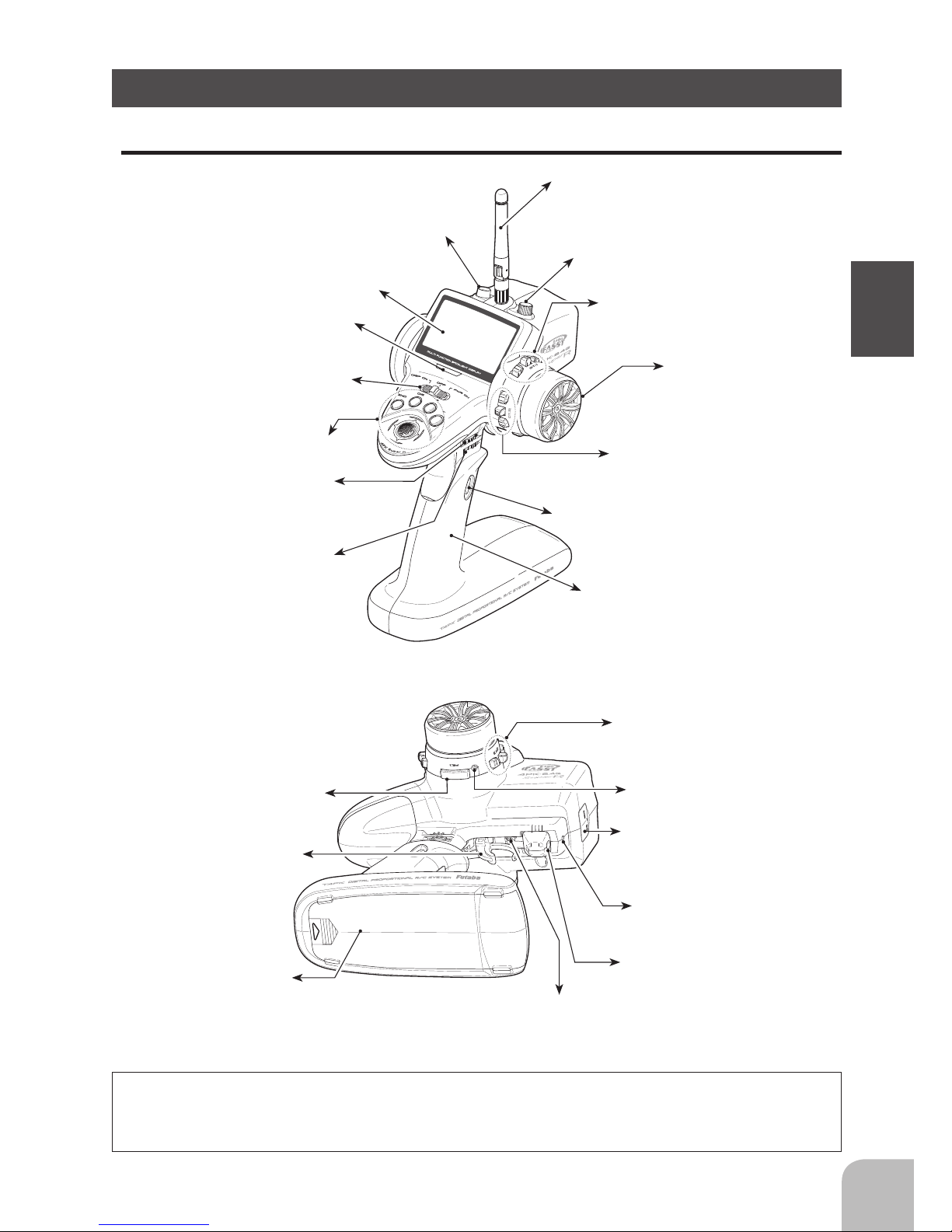
*The switches, dial, and trimmers in the gure are shown in the initial setting position.
Antenna
Precautions when turning the power switch on and off.
When the data is changed using the edit keys or trim levers, wait at least two seconds before turning off the power. If the power is
turned off within two seconds after the data is changed, the new data will not be written to memory.
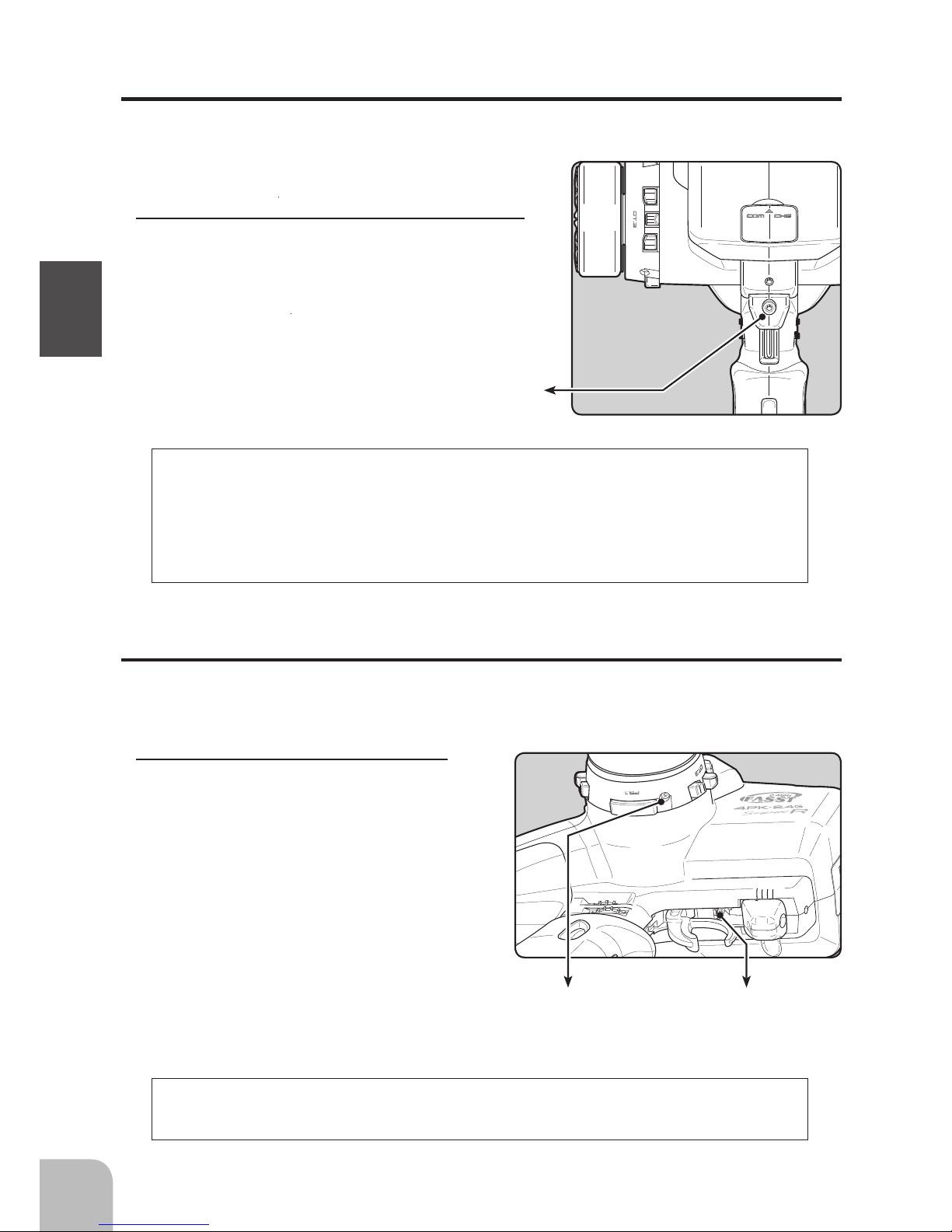
Digital Dial 3 (DL3)
Mechanical ATL
adjusting screw
Throttle trigger
Power&Display
switch
Digital Trim 2 (DT2)
(default throttle trim)
Grip Handle
Digital Trim1 (DT1)
(default steering trim)
Digital Trim 3 (DT3)
Digital Dial 1 (DL1)
(default dual rate)
Steering wheel
Push switch 2 (PS2)
Push switch 1 (PS1)
Push switch 3 (PS3)
LED
LCD screen
Edit buttons
Nomenclature
Transmitter T4PKSR
Digital Dial 2 (DL2)
(default ATL)
Wheel tension
adjusting screw
Trigger tension
adjusting screw
Battery cover
Cover
Trigger slide
adjusting screw
Page 16
"RF" is displayed
OFF
PWR ON
Radio waves are being
transmitted
DISP ON
Radio waves are not being
transmitted
"DISP" is displayed
16
Before Using
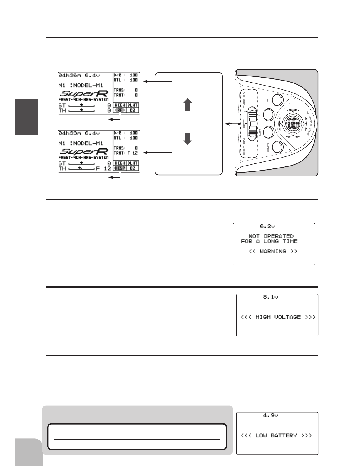
Power & Display Switch
The power switch and display switch of the T4PKSR are integrated. In the PWR ON
mode, radio waves are transmitted and in the DISP ON mode, model data, settings can
be checked without transmitting radio waves.
Power Off Forgotten Alarm
When the steering wheel, throttle trigger, push switch, or edit button are not operated
for 10 minutes default, an alarm sounds and "NOT OPERATED FOR A LONG TIME"
is displayed on the LCD screen.
When the steering wheel, throttle trigger, push switch, or
edit button are operated, the alarm is reset. If the system is
not to be used, turn off the power.
The function can be deactivated at the system menu (p.122).
High Voltage Alarm
If a battery exceeding 8V is used with the T4PKSR, an audible alarm will sound and "HIGH VOLTAGE" will be displayed on the LCD screen.
Immediately remove the battery because it may cause damage
to the T4PKSR.
Low Battery Alarm
If the transmitter battery voltage drops to 5.0V(when using dry cell battery: 4.2V) or
less, an audible alarm will sound and "LOW BATTERY" will be displayed on the LCD
screen.
Since Ni-MH and LiFe batteries have a different usable range than dry cell batteries, the
power source used must be selected at system setting (p.122).
Warning
When a low battery alarm is generated, cease operation imme-
diately and retrieve the model.
If the battery goes dead while in operation, you will lose control of the model.
Page 17
Steering trim display
Throttle trim display
Steering D/R DL1
ATL DL2
ATL display
Steering D/R
display
DT2 DT3
DT1
17
Before Using
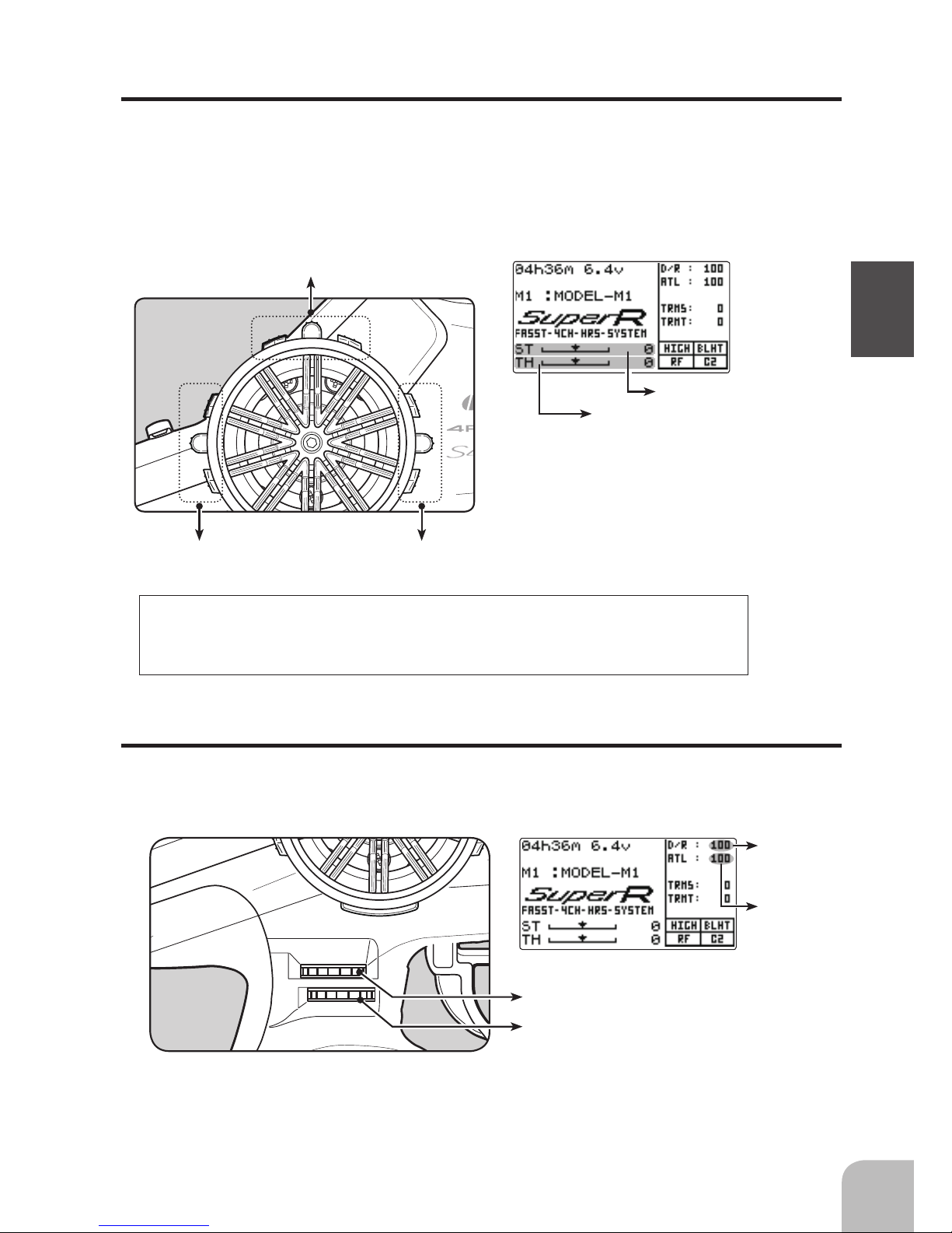
Trim Operation
Digital Trim Operation
(Initial settings: DT1: Steering trim, DT2: Throttle trim, DT3: -------)
Digital trims can be used in 2 ways:
Operating by the lever: Push the lever to the left or right (up or down) Operating by push
button switch: Press the push button switch in the desired direction. The current position
is displayed on the LCD screen in the bottom three rows of the list. However, this operation cannot be performed when the trim/dial lock (p.22) function is set.
• Each step is indicated by a tone.
• When the trim exceeds the maximum trim adjust-
ment range, the beep will change and the servo
will not move any farther. Return to the neutral
position (center) by pressing both the push button
switches simultaneously for about one second.
• Trim lever adjustments have no effect on the maximum servo travel.This prevents the linkages from
binding when adjustments are made.
Grip Dial Operation
(Initial setting: DL1; Steering D/R, DL2; ATL)
Operate the dials by turning them. The current set value is displayed on the LCD screen.
However, this operation cannot be performed when the trim/dial lock (p.22) function is set.
• Each step is indicated by a tone.
• When the trim exceeds the maximum trim adjustment range, the tone will change pitch and the servo will not
move any farther.
With the center trim feature, trim adjustments have no effect on the maximum servo travel. This prevents the linkages from binding when adjustments are made.
Page 18
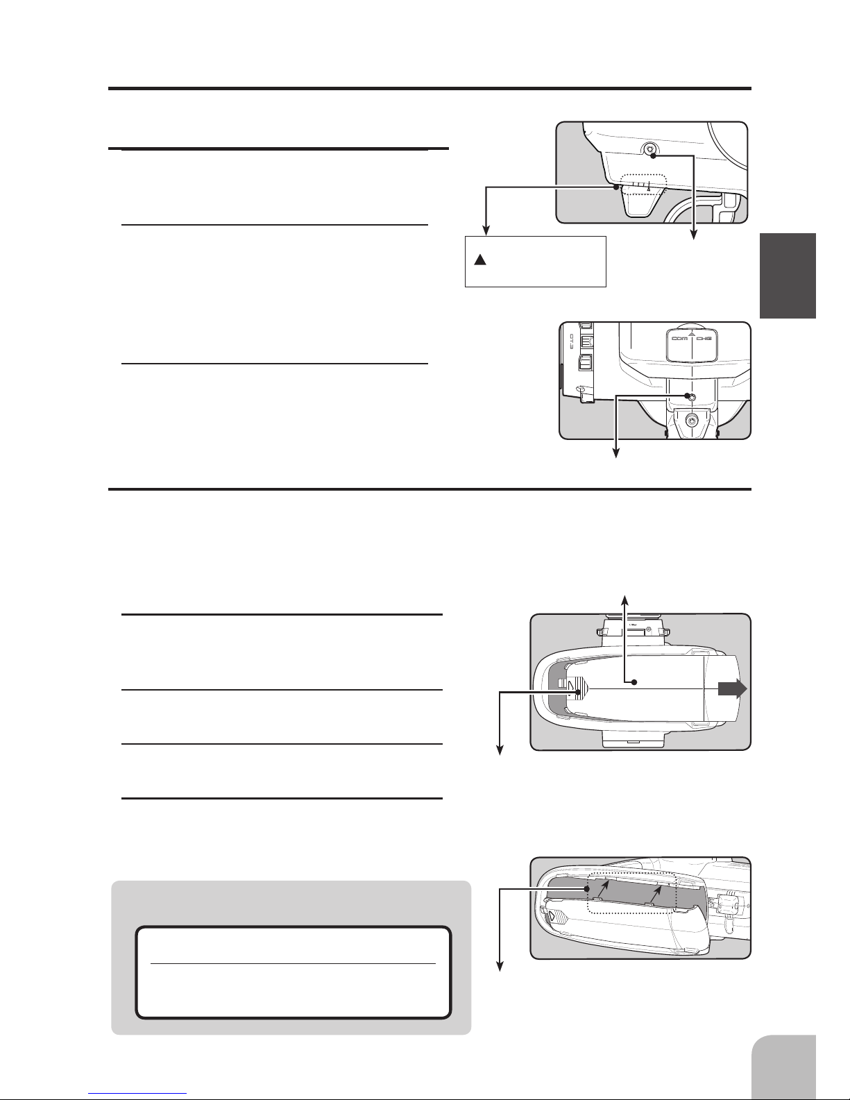
Mechanical ATL
adjusting screw
18
Before Using
Adjustment
1
Using a 2.5mm hex wrench, adjust the trigger
brake (reverse) stroke. (The screw moves the
throttle trigger stopper.)
• When the screw is turned clockwise, the stroke becomes
narrower. Adjust the stroke while watching the screw.
Note:
Mechanical ATL Adjustment
Make this adjustment when you want to decrease the stroke of the brake (back) side of
the throttle trigger for operation feel.
Wheel & Trigger Tension Adjustment
Make this adjustment when you want to change the wheel or trigger spring’s tension.
Adjustment
1
Using a 1.5mm hex wrench, adjust
the wheel spring tension by turning
the screw inside the adjusting hole in
the arrow direction.
• The spring is set to the weakest tension at the
factory.
• When the adjusting screw is turned clockwise,
the spring tension increases.
Note:
Wheel tension
adjusting screw
Once you have changed the mechanical stroke on the brake side, be sure to adjust
the scale of the throttle channel accordingly by using the "Adjuster Function"
(page 116).
Due to this change, you also need to adjust in most cases the travel of the throttle
servo by using "Data Setting."
The adjustment range is up to 7 to 8 turns from the fully tightened (strongest) position. If turned farther than this, the adjusting screw may fall out.
Trigger tension
adjusting screw
Page 19
Caution
Battery cover
Slide battery cover while pressing here.
19
Before Using
Ni-MH Battery Replacement
The Ni-MH battery is connected by a Futaba J connector so that it can be removed when
you will not be using the transmitter for a long time, or when replacing a dead battery
with a spare battery.
• Always use an HT5F1700B battery.
Removal
1
Slide the transmitter battery cover in the ar-
row direction while pressing the part shown
in the figure.
2
Remove the Ni-MH battery and disconnect
the connector.
3
Insert the connector of the new battery and
load the battery into the transmitter.
4
Finish by installing the battery cover.
Pay full attention so that the battery cover
does not pinch the cable of the Ni-MH battery.
Pinching the cable by the battery cover can lead to an
electrical shortage, fire and abnormal heat generation,
which may cause burns and fire disaster.
Trigger Slide Adjustment
The throttle trigger position can be moved forward and backward.
Adjustment
1
Using a 2.0mm hex wrench, loosen the
trigger slide mounting screw by turning it
slightly counterclockwise.
2
Using a 2.0mm hex wrench, turn the trig-
ger slide adjusting screw, and adjust the
trigger slide position within the marked
range. When the adjusting screw is turned
clockwise, the trigger slide moves away
from the grip handle.
3
Retighten the mounting screw loosened at
step 1 and fasten the trigger slide.
Trigger slide adjusting screw
Adjust so that the bottom
mark does not exceed
the top marking line.
Trigger slide
mounting screw
Install the cover by aligning the claws at both sides
of the battery cover with the grooves in the trans-
mitter shown in the gure and sliding on the battery
cover.
Page 20
Caution
Warning
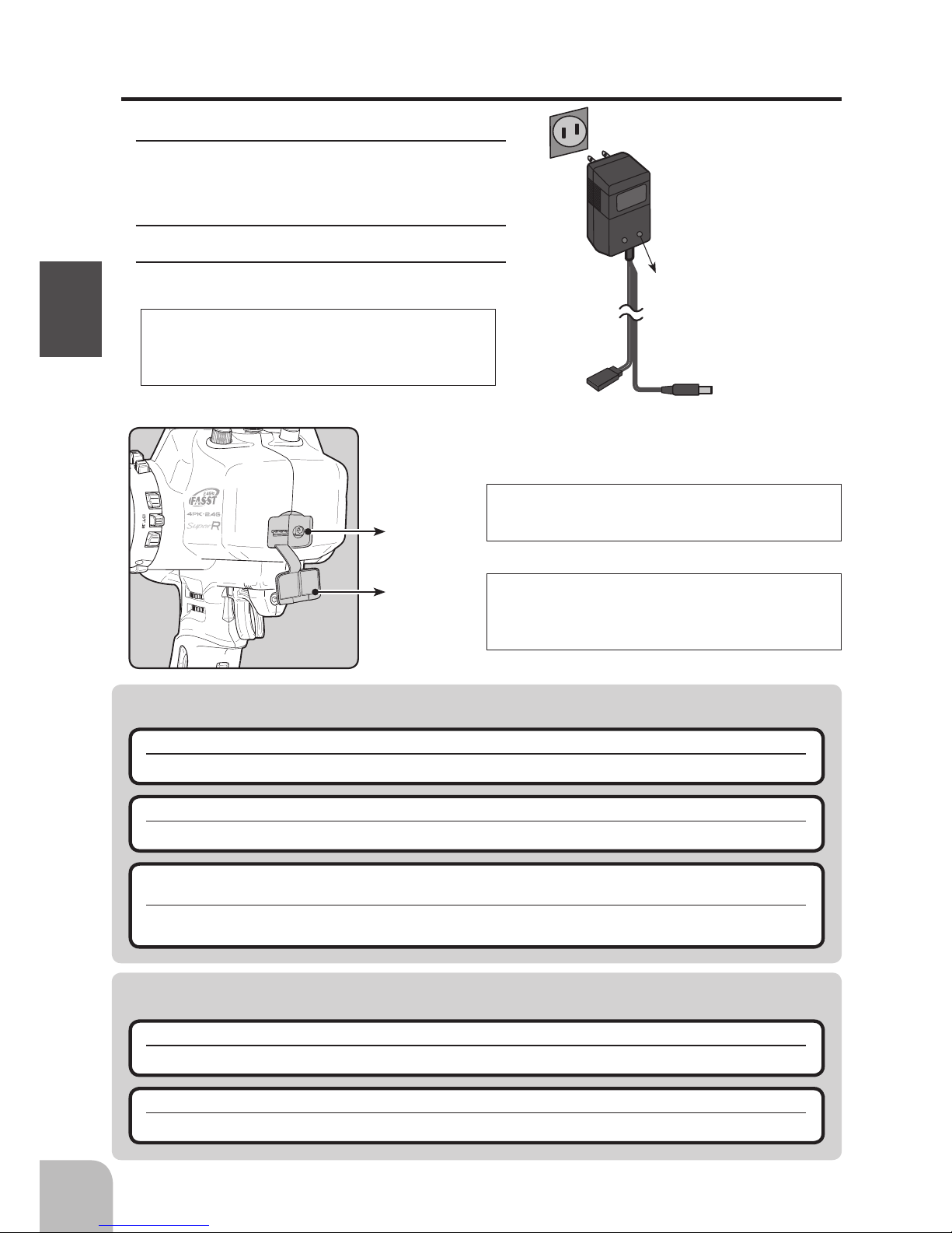
AC outlet
Charger
Transmitter charging
LED
To transmitter
charging jack
To receiver
Ni-Cd battery
20
Before Using
Over current protection
Charging
jack
Cover
The transmitter charging circuit is equipped with an over current protection circuit (1.7A). If the battery is charged with a
quick charger for other than digital proportional R/C sets, it
may not be fully charged.
When charging the HT5F1700B battery with the special charger, allow about 15 hours for charging. If the transmitter has
not been used for some time, cycle the battery by charging
and discharging it two or three times.
Never plug it into an outlet of other than the indicated voltage.
Plugging the charger into the wrong outlet could result in an explosion or re.
Do not insert and remove the charger when your hands are wet.
It may cause an electric shock.
Always use the special charger or a quick charger for digital proportional R/C sets to charge a
digital proportional R/C set Ni-MH battery.
Overcharging a Ni-MH battery can result in burns, re, injuries, or loss of sight due to overheating, breakage, or electrolyte leakage.
Never try to recharge a dry cell battery.
The transmitter may be damaged or the battery electrolyte may leak or the battery may break.
When the charger is not in use, disconnect it from the AC outlet.
Do this to prevent accidents and to avoid overheating.
Charging
1
Plug the transmitter cord of the special char-
ger into the charging jack on the rear of the
transmitter.
2
Plug the charger into an AC outlet.
3
Check that the charging LED lights.
Charging The HT5F1700B Battery
The HT5F1700B is 5-cells, so, when charging the
HT5F1700B battery with Futaba CR-2000 charger, you have
to use the RX output side.
When using Futaba CR-2000
Page 21
DL1
DL2
DL3
DT1
DT2
DT3
21
Before Using
Grip Vibrator
A vibrator is built into the grip of the T4PKSR. The vibrator vibrates at racing timer lap
navigation, time-up, and low battery alarm. (p.130)
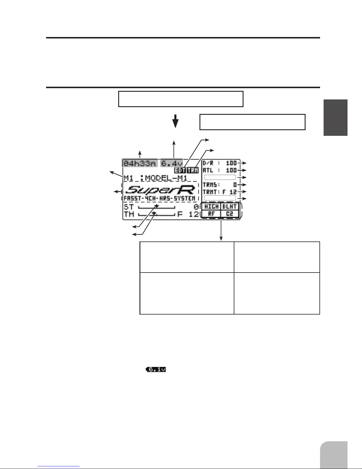
Total timer display (H:M)
Battery voltage display
Steering trim display
Throttle trim display
User name display
When the (END) button is held down for 1 second or longer at the initial screen, the
Futaba logo and user name are displayed for about 2 seconds.
Edit button lock display
Trim/dial lock display
Power switch turned on
Beep conrmation sound is generated and the
initial screen shown below appears.
Display when power switch is turned on
Function names and rate assigned to dials are displayed.
Display mode can be
changed by using the SYS-
TEM function. (See pge 108)
Model name (10 characters)
*The current servo mode (servo
response) is displayed.
The mode currently operating is
displayed. ("HIGH"/"NOR")
"BLHT" is displayed when
backlighting is ON.
When radio waves are being emitted, "RF" is displayed. When radio
waves are not being emitted when
turned on by display switch and
when the DSC function is used,
"DISP" is displayed.
*The current receiver type is
displayed.
The type currently operating is
displayed.
("C1"/"C2")
Power supply and voltage display
Dry cell batteries (alkali batteries are recommended) can be used with the optional battery box. However, when using dry cell batteries, set BATT-TYPE in the system menu
to DRY 4CELL. When BATT-TYPE is set to DRY 4CELL, the voltage display of the
initial screen will change to the
symbol.
When using the T4PKSR standard HT5F1700B battery, always set BATT-TYP to
NiMH5 LiFe2. (See page 110, for a detailed description of the battery types.)
Page 22
22
Before Using
Total Timer
The total timer shows the accumulated time from last reset.
The total time does not change even when the model changes.
Reset method
1
In the initial screen state, hold down the (+) and (-) buttons simultaneously for 1 second.
* The total timer display counts up from 1 minute to 99hours 59 minutes.
In the following cases, the LCD may become difcult to read due to a temperature
change.
- On hot summer days and cold winter days, the LCD may be easy to read indoors, but difcult to read outdoors.
- If the contrast is too bright or too dark, temperature changes and lighting conditions may cause the screen to
become difcult to read.
LCD Screen Temperature Change
LCD Screen Contrast
The LCD screen contrast can be adjusted. (For more information, see page 122.)
Caution
Do not adjust the contrast so that the LCD is too bright or too dark.
When the display cannot be read due to a temperature change, data cannot be set.
Contrast adjustment from main screen
1
Turn on the transmitter.
2
If the screen is too dark, adjust the contrast by pressing the (-) button while
pressing the (JOG) button. If the screen is too light, adjust the contrast by press-
ing the (+) button while pressing the (JOG) button.
Edit button lock and trim/dial lock
T4PKSR setup and operation by edit button (p.15) and digital trim DT1, DT2, and DT3
and dials DL1, DL2, and DL3 can be prohibited.
Setting
1
Edit button lock: When the (+) button is pressed for about 1 second at the initial screen,
a confirmation beep is generated and the edit button lock display appears on the
screen.
Trim/dial lock: When the (-) button is pressed for about 1 second at the initial screen,
a confirmation beep is generated and the trim/dial lock display appears on the
screen.
Clearing
1
Edit button lock and trim/dial lock can be cleared in the initial screen state by the same
method as the setting described above. (The edit button lock display or trim/dial
lock display disappears from the screen.)
Page 23
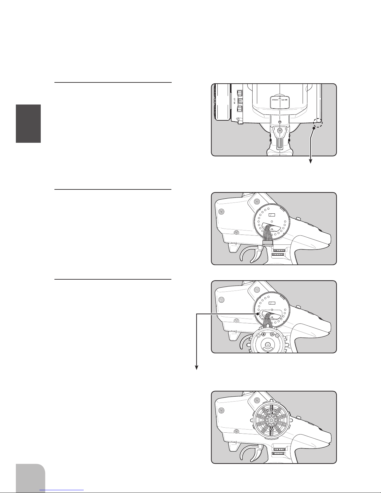
Changing wheel position and modifying for left-hand use
23
Before Using
Changing the wheel position
The wheel position can be offset by using the
accessory APA wheel position offset adapter.
(See page 24 for the modication method.)
Angle can be adjusted
The angle can be nely adjusted by adjusting the steering wheel unit installation. (See
the modication method on the next page for the adjustment details.)
The operating angle of the wheel can be adjusted.
The operating angle of the wheel can be changed from 34 deg to 32 deg by installing
the 32 deg wheel adjuster. (See "Removing the steering wheel unit" below for the replacement procedure.
If you install the 32 deg wheel adapter, be sure to adjust the scale of the steering
channel accordingly by using the "Adjuster Function"
(p.128).
Modifying for left-hand use
The wheel section left and right installation direction can be reversed.
(See page 26 for the modication method.)
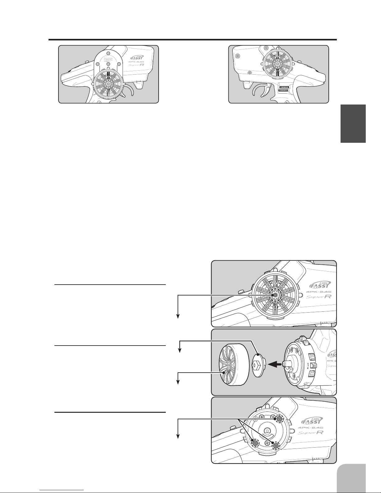
Removing the steering wheel unit
• Obtain 2.0 and 2.5mm hex wrenchs.
1
Hold the wheel and remove the
screw.
(Using a 2.5 mm hex wrench.)
Steering wheel
mounting screw
Unit mounting screws
2
Pull off the wheel and wheel
adapter.
Since the wheel adapter is 34 deg
as standard, install the 32 deg
wheel adapter at final installation.
3
Remove the 3 steering wheel unit
mounting screws.
(Using a 2.0 mm hex wrench.)
Wheel
Wheel adapter
Page 24
Unit mounting screws
24
Before Using
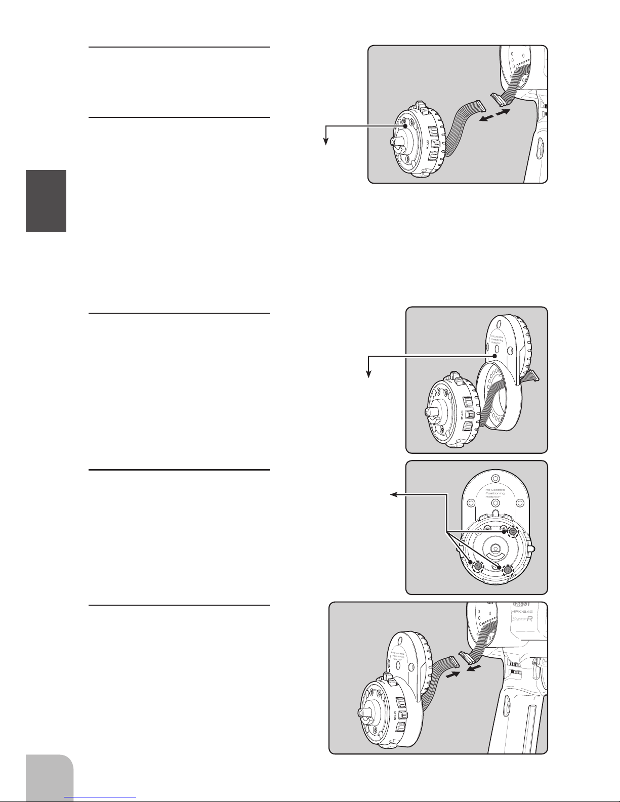
4
Remove the steering wheel unit.
•Be careful not to stretch the wiring.
5
Disconnect the steering wheel
unit connector.
Installing the accessory APA steering wheel offset adapter
1
The steering wheel unit connector
through the adapter.
• Obtain 2.0 and 2.5mm hex wrenchs..
• Install the steering wheel unit, removed as described on the preceding page, as follows:
• The length of the screws used at each part differs .When reassembling the steering wheel unit, always use the
original screws.
Wheel unit
2
Install the steering wheel unit us-
ing the 3 mounting screws.
(Using a 2.0 mm hex wrench.)
Adapter APA
3
Connect the steering wheel unit
connector.
(Pay close attention to the direction of the connector.)
Page 25
25
Before Using
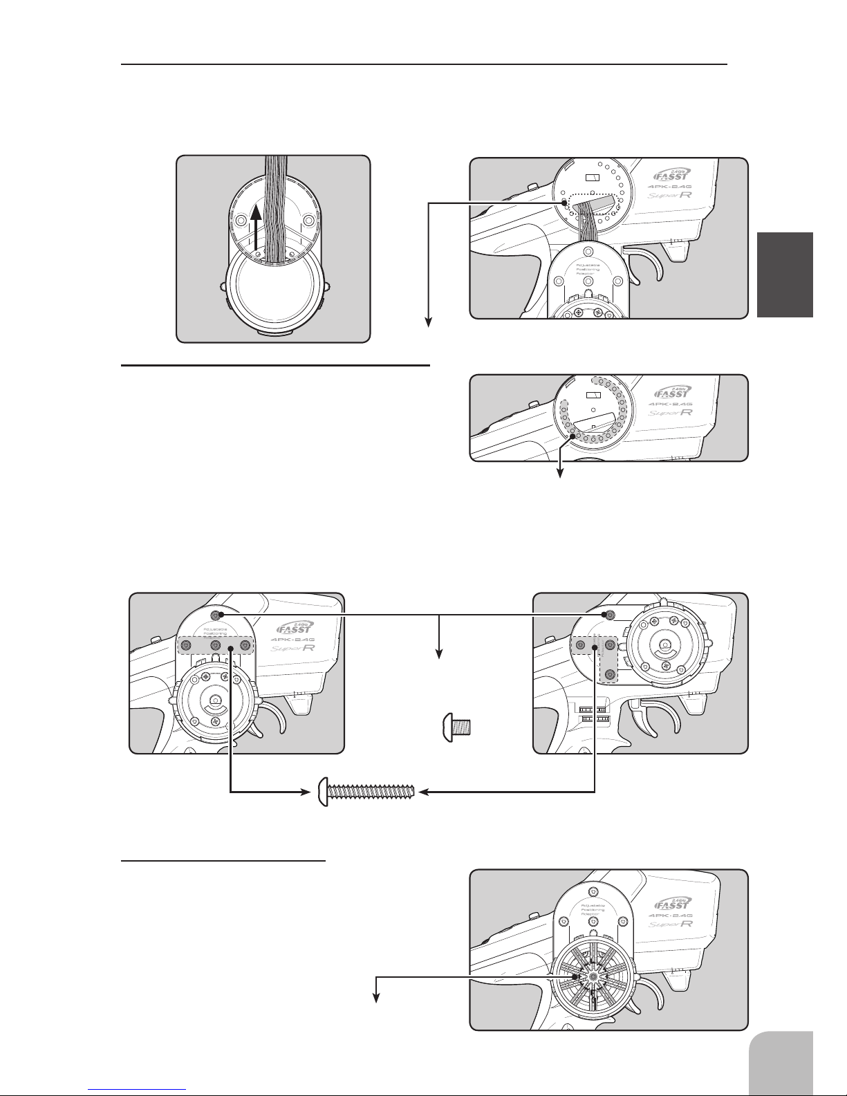
3
Pull out the wiring as far as possible from between the wheel unit and APA. Stow the
surplus pulled out wiring in the transmitter.
•Be careful not to stretch the wiring.
4
Install the assembled wheel unit and APA
to the transmitter using the screw supplied.
The APA mounting screws are in the hook
and APA mounting screws bag.
Verify the position of the transmitter bottom
holes by mounting angle. The screw used
depends on the position of the bottom hole.
(Using a 2.0 mm hex wrench.)
Stow the surplus wiring here.
Transmitter bottom hole
*The gure below is an installation example.
Dummy screw
Du m my sc r ews (4 x 4 scre w)
hide the APA hole where there is
no bottom hole in the transmitter.
Use (3 x 20 tapping screw) to install the APA at the 3
bottom holes in the transmitter
Steering wheel mounting screw
5
Install the steering wheel
using the screw.
(Using a 2.5 mm hex wrench.)
Page 26
26
Before Using
Modifying for left-hand use
1
Remove the wheel section rear
cover .
• The rear cover can be easily removed by inserting a coin, etc. into the slot at the bottom
of the rear cover.
• Obtain 2.0 and 2.5mm hex wrenchs.
• Install the steering wheel unit removed as described on the preceding page as follows:
2
Push in the disconnected connector
so that it can be connected at the
opposite side.
3
At the opposite side, connect the
steering wheel unit connector and
Install the steering wheel unit,
steering wheel cover, and wheel to
their original positions.
• At this time, be sure that the wiring is not
pinched between the wheel unit and transmitter.
Stow the surplus wiring here.
Page 27
27
Before Using
Grip rubber
Hook
Hook mounting screw
Hook
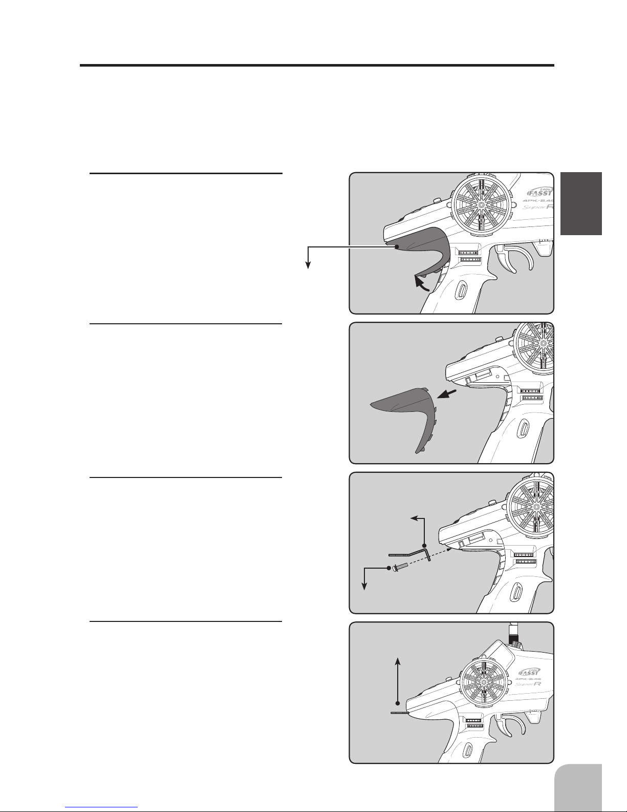
A hook can be installed to the T4PKSR, as required.
The hook is in the hook and APA mounting screws bag supplied with the set.
• Obtain a 2.5mm hex wrenchs.
• Pull up the grip rubber.
2
Pull out the grip rubber in the arrow
direction.
3
There is a mounting nut inside the
transmitter. Install the hook at the
position shown in the figure using
the accessory screw w/washer.
(Using a 2.5 mm hex wrench.)
1
Pull up the bottom of the grip rub-
ber as shown in the figure.
4
Return the grip rubber to its original
position.
Installing the accessory neck strap hook
Page 28
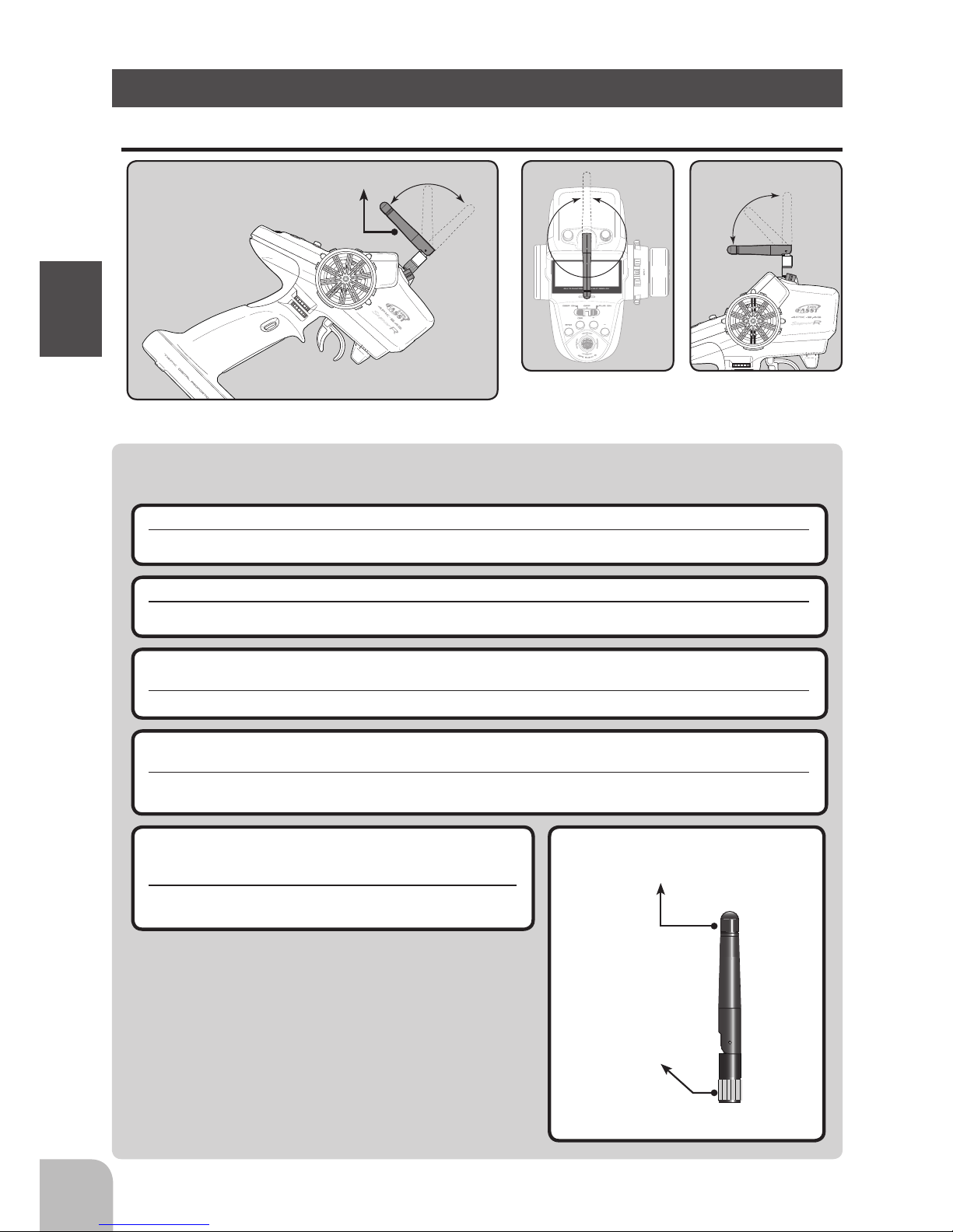
Warning
Antenna Moving Range
Adjust the antenna ver tically to the ground.
Antenna
A B
When the antenna is
changed, it requires the
me tal par t o f the antenna to b e held firmly
while putting it on.
Antenna
28
Before Using
About The Transmitter Antenna
Adjust the antenna vertically to the ground.
Otherwise, the operating range may become shorter.
The antenna position can be changed in the range as shown in figures A and B. However, please
do not apply unnecessary force or shock.
The internal cable may be damaged; thus transmitting distance decreases and it may cause malfunction.
Never hold only the antenna.
Hold the grip handle. Otherwise, the antenna may be damaged.
About Transmitter Antenna and Receiver
The antenna is a screw-on type and can be removed. However, do not remove the antenna ex-
cept when it must be replaced.
If the transmitter antenna terminals get dirty, the radio wave output will become weak and there is the danger that the
receiving range will be substantially shortened.
When the antenna is changed, it requires the metal
part of the antenna to be held firmly while putting it
on.
The antenna cannot be mounted to T4PKSR (by rotating the
middle part of the antenna).
There might be small glitch when the antenna
of the transmitter is brought close to servos,
ESCs or other peripheral devices.
This is not an issue but please keep this symptom in mind, especially when setting-up.
Page 29
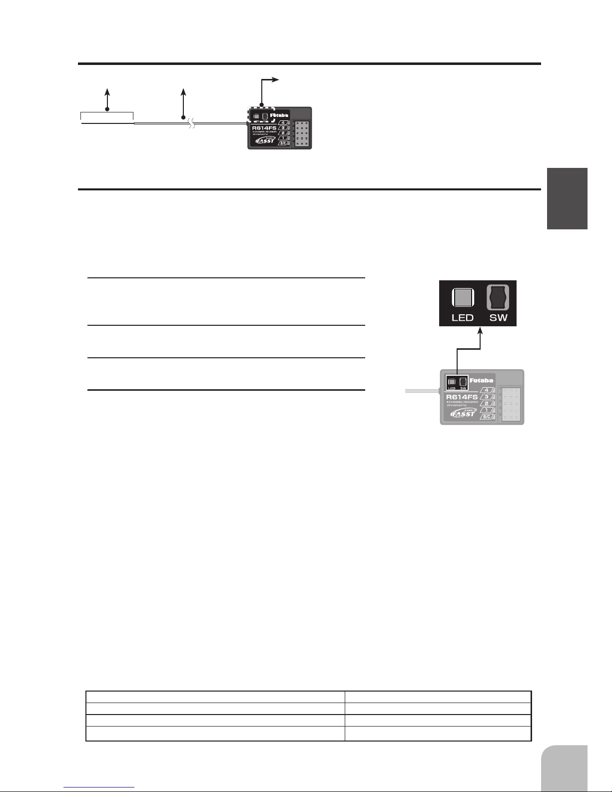
Antenna Coaxial cable
Tactile switch/ LED
29
Before Using
Receiver Terminology
How to link the transmitter and the receiver
Each transmitter has an individually assigned, unique ID code. In order to start operation, the receiver must be linked with the ID code of the transmitter to which it is being
paired. Once the link is made, the ID code is stored in the receiver and no further linking is necessary unless the receiver needs to be used with another transmitter.
Link procedure
1
Bring the transmitter and the receiver close to each
other, within 20 inches (half meter).
2
Turn on the transmitter.
3
Turn on the receiver.
4
Push the tactile switch of the receiver.
When the link is complete, the LED in the receiver
changes to solid green.
When the ID cannot be read due to the surrounding
environment, try reading it with the transmitter and receiver antennas touching.
Connectors
4 :CH4 servo(CH4)
3 :CH3 servo(CH3)
2 :Throttle servo(CH2)
1 :Steering servo(CH1)
B/C :Power connector/DSC connector
No signal reception Red : On
Receiving signals Green: On
Receiving signals, but ID is unmatched. Green: Blink
Unrecoverable failure (EEPROM, etc.) Red and Green turn on alternately
LED status vs receiver's condition:
Precaution:
If there are many FASST systems turned on in close proximity to the R603FS/R603FF/R604FS(E)/
R614FF, your receiver might not link to your transmitter. In this case, even if the receiver's LED stays sol-
id green, unfortunately the receiver might have established a link to one of other transmitters. This is very
dangerous if you do not notice this situation. In order to avoid the problem, we strongly recommend you
to double-check whether your receiver is really under control by your transmitter by giving the stick input
and then checking the servo response.
Warning
After the linking is done, please cycle receiver power and check if the receiver to be linked is really
under the control of your transmitter.
Do not perform the linking procedure with motor's main wire connected or the engine operating as
it may result in serious injury.
*Please refer to the table below for LED status vs receiver's condition.
Page 30
WARNING
Caution
Antenna
tube
Antenna
Coaxial
cable
R614FS
30
Before Using
Always use R614FS / R614FF-E under the following conditions:
Battery :Power requirement Rated voltage 3.7V~7.4V
Matched to the ratings of the receiver and connected servo (digital servo cannot use the dry battery).
RX Type :FASST-C2(See p.46 for setting method.)
Transmitter mode-HIGH SPEED mode :Futaba digital servo(See page 46 for setting method.)
Transmitter mode-NORMAL mode :Futaba all servo(See page 46 for setting method.)
Under other conditions, the set will not operate, or the specified performance will not be displayed even if it operates. In
addition, it may cause trouble with servos and other equipment. Futaba will not be responsible for damage, etc. caused
by combination with the products of other companies.
Receiver Installation
Install the R614FS receiver on the car as follows:
The operating range may become shorter, depending on where the receiver and the antenna are mounted.
Do not cut or bundle the receiver antenna wire.
Do not bend the coaxial cable. It causes damage.
Install the antenna in the higher place as shown in the figure.
Put the antenna in the antenna tube to protect it.
Note:
Since the receiver generates a certain amount of heat, change the mounting method to improve the ventilation
at the receiver. If the receiver is too tight, it may malfunction when the ambient temperature is high.
Transmitter mode setting
Set the transmitter to the HIGH SPEED mode or NORMAL mode. See page 46 for a description of
the setting method.
Note:
However, digital servos (including BLS Series brushless servo) can only be used in the HIGH SPEED mode.
When the power is turned on, whether the receiver is in the HIGH SPEED or NORMAL mode is judged and the R604FS operates in that mode until the power is turned off. When the transmitter mode is changed, operation becomes possible when the
receiver power is turned on again. When the frequency band is changed, reception on the new frequency band becomes possible
when the receiver power is turned on again.
For the receiver, servos, and other connections, see page 31 for the DSC cord (option)
connections, see page 137.
Keep the antenna as far away from the motor, ESC and other
noise sources as you possibly can.
Wrap the receiver with something soft, such as foam rubber, to
avoid vibration. If there is a chance of getting wet, put the receiver
in a waterproof bag or balloon.
Page 31

B/C
CH3
CH2
CH1
CH4
Receiver
Switch
To Battery
Steering servo
Throttle servo
CH3 servo
CH4 servo
#%$
31
Installation
Connect the receiver and servos as shown below. Connect and install the receiver and
servos in accordance with "Installation Safety Precautions" on the next page.
The gure shown below is an example. The method of connecting the motor controller
to the motor and battery depends on the motor controller used. Purchase the motor con-
troller and servos separately. The receiver also depends on the set.
When using the DSC cord with a gasoline engine car, connect the optional double extension cord to B/C of the receiver and the DSC cord and receiver switch to the opposite
side connector.
Installation When An Electronic Speed Control Is Used
Installation For Gas Powered Models
Installation
Receiver and Servo Connections
Page 32

Installation Safety Precautions
Warning
32
Installation
Receiver (receiver antenna)
Receiver Vibration-proofing / Waterproofing
Do not cut or bundle the receiver antenna wire.
Do not bundle the receiver antenna wire together with the motor controller lead wire.
Keep the receiver antenna wire at least 1cm away from motor, battery, and other wiring carrying heavy current.
Do not use a metal receiver antenna holder on a plate made of metal, carbon, or other conductive material.
Install the receiver antenna holder as closely as possible to the receiver.
If the antenna wire is cut, bundled, or routed near a noise source, the receiving sensitivity will drop, the running (sailing)
range will decrease, and you may lose control of the model.
*Noise is transmitted through metal, carbon, and other conductive material, so keep the receiver antenna wire away from such parts.
(Car)
Vibration-proof the receiver by wrapping it in foam rubber or other vibration-absorbing material
and mount it with thick double-sided tape.
When using the receiver holder supplied with the model kit, mount the holder to the chassis
through a rubber grommet.
(Boat)
Vibration-proof the receiver by wrapping it in foam rubber or other vibration-absorbing material.
Also waterproof the receiver by sealing it in a plastic bag.
If the receiver is exposed to strong vibration and shock, it will operate erroneously due to the invasion of water drops and
you may lose control of the model.
Screw
Mechanical plate
Nut (as required)
Receiver holder
Damper
When using the receiver holder sup-
plied with the kit, install the receiver
through a rubber grommet.
Foam rubber, etc.
Wrap the receiver in foam rubber or other
vibration-absorbing material. Do not use
hard material. Hard material does not
have a vibration-proong effect.
Mechanical plate
Thick doublesided tape
When mounting the receiver with double-sided tape,
do not use a stiff tape. Stiff tape does not have a vibra-
tion-proong effect.
#%$
Antenna
Install the receiver as far away as possible from the battery, motor controller, motor, silicon cord and other noise
sources. Keep it away from the antenna wire, in particular.
Antenna holder
Install the antenna holder as close as possible to the
receiver. The surplus antenna wire from the receiver
to the antenna holder is affected by noise. Do not use
a metal antenna holder on a plate made of metal, carbon, or other conductive material.
Antenna wire does
not touch the plate.
Battery
Page 33

Warning
33
Installation
Connector Connections
Servo Installation
Be sure the receiver, servo, battery and connectors are fully and firmly connected.
If vibration from the model causes a connector to work loose while the model is in operation, you may lose control .
When you install the servos, always use the rubber grommets provided in servo hardware bags.
Mount the servos so they do not directly come in contact with the mount.
If the servo case comes in direct contact with the mount, vibration will be directly transmitted to the servo.
If this condition continues for a long time, the servo may be damaged and control will be lost.
Servo Throw
Operate each servo over its full stroke and be sure the linkage does not bind or is loose.
The continuous application of unreasonable force to a servo may cause damage and excessive battery drain.
Screw
Mechanical plate
Nut (as required)
Eyelet
Damper
(or)
When installing the servo, always install the accessory
rubber grommet and grommet ush against the servo.
A vibration-damping effect is not obtained even
if the rubber grommet and grommet are not in-
stalled correctly.
Adjust the throttle servo so that unreasonable force is
not applied when the engine carburetor is fully open,
fully closed, and the brakes are applied fully.
If the brakes overheat while running, their ability to
function properly decreases. Before running, adjust the
suitable maximum servo travel so that unreasonable
force is not applied even when the servo travel is increased while running.
Adjust the steering servo so that unreasonable force is not applied to the servo by the
chassis at maximum servo travel.
Decide the EPA value at the
contact point.
Caution!
A howling noise indicates that the
steering servo is improperly set.
Page 34

Warning
34
Installation
Electronic Speed Control
Motor Noise Suppression
Install the heat sinks where they will not come in contact with aluminum, carbon fiber or other
parts that conduct electricity.
If the FET Amp (Electronic speed control) heat sinks touch other materials that conduct electricity a short circuit could
occur. This could result in loss of control and damage to the system.
Always install capacitors to suppress noise when electric motors are used.
If capacitors are not properly installed you could experience erratic operation and reduced range as well as loss of control.
Other Noise Suppression Methods
Be sure there are no metal parts in your model which under vibration can come in contact with
other metal parts.
Metal to metal contacts under vibration will emit a high frequency noise that will affect the receiver's performance. You
could experience erratic operation and reduced range as well as loss of control.
Motors with no suppressor capacitors, or inadequate suppression, may cause the receiver to malfunction. Always solder the capacitors supplied to
your motor.
The Schottky diode improves the efciency of the
speed control / motor combination and provides
extra protection to the brake FETs. The white ring
must always face the positive side.
Schottky diode
"-" side
"+" side
1 2 3
Page 35

When radio waves are not being emitted when
turned on by display switch and when the
DSC function is used, "DISP" is displayed.
"RF"
When FASST-C2
"C2"
35
Initial Set-Up
Before setting the Transmitter functions, check and set items 1 to 5 below.
Initial Set-Up
Preparations (Transmitter)
(Display when power switch turned on)
When the power switch is turned on, the currently selected model number is displayed.
Check if this number is the model number you want to set-up. To change the model
number, use the Model Select function (See page 108).
(Start screen)
Turn on the transmitter power.
The model number is displayed.
1.RF Output Check
If signals are output normally, RF output monitor "RF" will be displayed on the screen.
If "RF" is not displayed, contact your Futaba dealer.
When radio waves are not being emitted when turned on
by display switch and when the DSC function is used,
"DISP" is displayed.
2.Rx Type Check
The T4PKSR transmitter can use the Futaba 2.4GHZ R603FS/FF. However, there
are two types of Futaba 2.4GHz receivers for vehicles: "C1" type and "C2" type. The
R603FS and 603FF are "C1" type. The R614FF supplied with
the 4PKS set as standard is the "C2" type. Check that the setting matches the receiver being used. For example, when using
the R614FF, the receiver type must be set to FASST-C2 and
when using an R603FS or R603FF, the receiver type must be
set to FASST-C1. If the setting is wrong, change it using the
RX/SX type select function (See page 46).
Page 36

When HIGH SPEED
"HIGH"
Throttle trim (DT2)
Steering trim (DT1)
Steering trim
Throttle trim
36
Initial Set-Up
5. Trims Initial Set-Up
- Steering trim (DT1) check
On the initial set-up, steering trim is assigned to the DT1
trim lever above the steering wheel. Operate the lever and
make sure the marker moves on the ST graph. If default
has been changed, test steering trim in its new location.
After checking the trim, set the trim display to the center
(N) position.
3. Servo Response Mode Check
Check that the servo response setting matches the servo being used. When using a digital servo (including BLS Series
brushless servo), both HIGH SPEED and NORMAL can be
used. When an analog servo is used, HIGH SPEED cannot be
used; therefore, servo response must be set to NORMAL. If
the setting is wrong, change it using the RX/SX type select
function (page 46).
- Throttle trim (DT2) check
On the initial set-up, throttle trim is assigned to the DT2
trim lever on the left side of the steering wheel. Operate the lever and make sure the marker moves on the TH
graph. If the default has been changed, test the throttle
trim in its new location. After checking the trim, set the
trim display to the center (N) position.
4. Throttle Mode Check
-When using the T4PKSR transmitter with a boat, throttle
brake operation can be shut down by setting the BOAT function (p.78) *TRG-BRK item to "Cut-OFF".
-The throttle servo travel can be set to 50:50 or 70:30 for throttle trigger operation as required by the throttle mode function
(page 80).
Page 37

Throttle ATL
Steering dual rate
37
Initial Set-Up
(Set-Up Procedure When Installed In a Car)
When installing the servos in a car, performing function set-up in the following order is
recommended.
1
Perform step 1 to 5. Trims Initial Set-Up of Preparations on the preceding
page.
2
Set the servo direction of operation using the Reverse function. (p.47)
- The servo installation method and linkage direction depend on the kit. Therefore, the servo
operation direction may have to be reversed relative to transmitter operation. Before installing the servo, check the operating direction and set it using the Reverse function.
3
Set the subtrim and adjust the servo neutral point. (p.48)
4
Set the trigger travel by adjusting the throttle trigger mechanical ATL to
your liking. (p.18)
- When the stroke was adjusted, compensate the throttle by adjuster function (See page116).
5
Set EPA of each channel and adjust the servo throw (travel). (
p.49
)
Steering dual rate dial DL1
Throttle ATL dial DL2
- Steering dual rate (DL1) check
At initial set-up, steering dual rate (D/R) is assigned to DL1
dial, at the grip of the transmitter. Operate the DL1 and
check if the D/R value displayed on the screen changes. After
checking ST.D/R, set the steering dual rate to 100%.
- Throttle ATL (DL2) check
At initial setting, throttle ATL (ATL) is assigned to DL2 dial,
below DL1. Operate the DL2 and check if the ATL value displayed on the screen changes. After checking TH.ATL, set
throttle ATL to 100%.
Page 38

38
Function Map
Function Map
Menu Selection
The function set-up screen can be easily selected from the function menu displayed on
the LCD screen.
The function menu can be selected from among the following 4 types to match the level
of use. To select the type, use the Menu type select function (page 113).
-Level 1 (LEVEL1) : Basic functions only
-Level 2 (LEVEL2) : For middle class driver
-Big car(BIGCAR) : Displays the main functions for large cars (1/5).
-Level 3 (LEVEL3) : All functions can be selected. (For expert driver)
* In addition to the menu types shown above, there is ALLOFF. It is convenient when customizing all menus.
This menu consists of 3 xed functions; *M-SEL (model select), *M-RES (model reset), and * MENU-T (menu type select),
and cannot be moved or deleted.
Function Menu Screen
Pus
h
Push
Push
Push
LEVEL1
LEVEL2
BIGCAR
LEVEL3
(Opening Screen)
Switch MENU1 and MENU2 by
pressing the
button.
Push
Call the menu screen by
button up, down, left,
or right operation.
Press the button to re-
turn to the Start Screen
Edit Buttons
In this instruction manual,
Edit Buttons are represented
by the symbols shown at
right.
Page 39

Push
Push
Menu No. of the function indicated
by the cursor is displayed.
When the cursor is in a position without
a function assigned, "OF" is displayed.
The screen above is an example
of the LEVEL2 MENU1 menu.
39
Function Map
(Function Set-up Screen)
Example of menu LEVEL2
Call the menu screen by
button up, down, left, or
right operation.
press the button to re-
turn to the Start Screen
Push
(Opening Screen)
press the
button to re-
turn to the Start Screen
Th e s creen o n the rig h t
shows an example of setting
EPA function.
Call the setup screen by
pressing the
button.
Menu Screen
The menu screen displays 18 items on 3 rows and 6 lines on one page and displays up to
36 items on 2 pages designated MENU1 and MENU2.
A menu screen matched to the
purpose can also be created by
using the menu customize functions described on page 40. The
menu No. of the function indicated by the cursor is displayed
at the top right-hand corner of
the screen. When a function is
not assigned, "OF "is displayed
at the top right-hand corner of
the screen.
Calling the setup screen
On the menu screen, select the
function by moving the cursor by
button up, down, left, or right
operation.
The highlighted item is the currently selected function.
Push
Switch MENU1 and MENU2 by
pressing the
button.
Page 40

Push
(CUSTOMIZE MENU screen)
(MENU1 screen)
(MENU2 screen)
PushPush
The highlighted item is the currently selected function.
(Opening Screen)
(approx. 1sec)
40
Function Map
Custom Menu
A menu matched to the purpose (custom menu) can be created by using the menu customize function.
A different menu can be created for each model memory.
In addition, custom menus can be copied to other models by using
menu copy of the model copy function (p.110). There is a method
which modies the arrangement or adds (other than LEVEL3) or
removes menus locally from the LEVEL1, LEVEL2, BIGCAR,
and LEVEL3 basic menus and a method which changes all the
menus to personal use only.
1
Call the menu screen from the initial screen by (JOG) button
up, down, left, or right operation.
2
Use the (+) button to Select the MENU1 or MENU2 screen
to be edited.
3
Press the (-) button for about 1 second. A confirmation beep
is generated and the menu customize screen is displayed.
4
Select the location where the function is to be assigned or
modified by moving the cursor by (JOG) up, down, left, or
right operation.
5
Use the (+) or (-) button to select the function to be assigned.
6
When assignment is complete, end by returning to the menu
screen by pressing the (END) button.
Menu assignment
One point
This function allows modication of the menu list and
addition (except LEVEL3) or removal of functions. All
the functions can also be grouped at MENU1 only depending on the purpose.
PushPush
Example of setting BRAKE (brake mixing) where nothing
was set at LEVEL2 MENU1.
or
Page 41

PushPush
Push
Push
Push
Push
Push
Push
Push
(MENU1 screen)
(MENU2 screen)
(CUSTOMIZE MENU screen)
or
and
(Opening Screen)
(MENU1 screen)
(MENU TYPE screen)
(approx. 1sec)
41
Function Map
Note:
This function consists of 3 xed functions; *M-SEL (model select), *M-RES
(model reset), and * MENU-T (menu type select), and cannot be moved or de-
leted.
When the menu type is changed from the created customize menu to another
menu type by * MENU-T, the customize menu is reset and the menu is initialized to the original menu.
The set values of a function deleted from the menu remain valid. When an unused function is turned OFF or rate adjustment, etc. related to other functions is
performed, check the set values before deleting the function.
In addition to the menu types shown page 38, there is ALLOFF. It is convenient when customizing all functions.
1
Call the menu screen from the initial screen by (JOG) button
up, down, left, or right operation.
2
On the MENU1 screen, move the cursor to "*MENU-T" by
(JOG) button up, down, left, or right operation and press the
button.
3
(Menu type selection)
After the MENU TYPE screen is displayed, select the setting
item "TYPE" with blinking cursor by (JOG) button up or down
operation. Change "TYPE" by pressing (+) or (-) buttons.
Example-select "ALLOFF".
4
(Menu type modification)
Select "EXEC" with blinking cursor by (JOG) button up or
down operation. Press the (+) and (-) buttons simultaneously
for 1 second.
- Operation is completed when "COMPLETE!" blinks on the screen.
5
Return to the menu screen by pressing the (END) button.
Use the (+) button to select the MENU1 or MENU2 menu
screen to be edited.
6
Press the (-) button for about 1 second. A confirmation peep-
ing sound is generated and the menu customize screen is
displayed.
See steps 4 and 5 on page 40 for a description of the menu
assignment method.
Customizing all functions.
Page 42

1 7
8
2,3,4,5,6
42
Function Map
Direct Selection
The Direct Selection allows instant access to the six functions most frequently used.
The function set-up screen can be directly and quickly called with the special buttons
for each of the eight functions. They can be freely selected by pressing "Direct Selection
Button" (DIR) function.
(Opening Screen)
(Direct Selection Screen)
(Function Set-up Screen)
Call the direct Selection
screen by pressing the
button.
press the button to return
to the Direct Selection Screen
press the button to re-
turn to the Start Screen
Upon your needs, select one of the
8 functions and then click its button
to call the Function Set-up Screen.
Direct
No
Button
Function ab-
breviation
Function
1.
Press
EPA
Chanel End
Point Adjuster
2.
STSPD
Steering Speed
3.
STEXP
Steering EXP
4.
Press
SUBTR
Subtrim
5.
THEXP
Throttle EXP
6.
THSPD
Throttle Speed
7.
Press
M-SEL
Model Select
8.
Press
A.B.S
A.B.S
Initial Setting
The screen on the
le f t s hows a n exam p le of
Throttle
EXP
function.
Press the but-
ton to return to the
Opening Screen
Page 43

PushPush
Push
3 seconds or longer
1 7
8
2,3,4,5,6
43
Function Map
Setup items
1: Function assigned to button No. 1
2: Function assigned to button No. 2
3: Function assigned to button No. 3
4: Function assigned to button No. 4
5: Function assigned to button No. 5
6: Function assigned to button No. 6
7: Function assigned to button No. 7
8: Function assigned to button No. 8
Direct selection function assignment
1
The setup screen of this function is called by pressing the
(DIR) button for 3 seconds or longer from the initial screen.
2
(Direct button selection)
Select the function you wish to customize (No.1~8) by (JOG)
button up or down operation.
3
(Assignment function selection)
Change the function by pressing the (+) or (-) button.
4
When ending setting, return to the initial screen by pressing
the (END) button and (DIR) button one time each, in that order.
Direct Customize
With the T4PKSR, your favorite direct call matched to the purpose can be assigned to
the edit buttons by using the direct customize function.
Direct call lets you create a different menu for each model memory.
Direct call assigned to each edit button can also be copied to other models by using
menu copy of the model copy function (p.110).
(Opening Screen)
(Direct Customize Screen)
Page 44

44
Function Map
Function
No
Function abbreviation
LEVEL1 LEVEL2 BIGCAR LEVEL3
1
EPA
2
STEXP
3
STSPD
4
THEXP
5
THSPD
6
A.B.S
7
ACCEL
8
START
9
BRAKE
10
IDLUP
11
TIMER
12
LAP-L
13
P-MIX
14
S-MIX
15
BOAT
16
SUBTR
17
REV
18
F/S
19
*
M-SEL
20
*
M-RES
21
M-COP
22
NAME
23
DIAL
24
SWTCH
25
D/R
26
ATL
27
CH3/4
28
RXSYS
29
*
MENU-T
30
SYSTM
31
DTTRN
32
SERVO
33
MCLNK
34
ADJST
35
VIBRA
36
THMOD
List of functions by menu type
(Initial setting)
Page 45

45
Function Map
Function
No
Function
abbreviation
Description of function
Page
No
1
EPA
End point adjustment
P-49
2
STEXP
Steering curve adjustment
P-56
3
STSPD
Steering servo delay
P-61
4
THEXP
Throttle curve adjustment
P-57
5
THSPD
Throttle servo delay
P-63
6
A.B.S
Pumping brake
P-69
7
ACCEL
Function which adjusts the rise characteristic from the throttle neutral position
P-52
8
START
Throttle preset at start function/ engine cut off by switch
P-66
9
BRAKE
Front and rear independent brake control for 1/5GP car, etc.
P-74
10
IDLUP
Idle up at engine start
P-82
11
TIMER
Up, down, lap, or lap navigation timer
P-100
12
LAP-L
Lap timer data (lap time, average lap time) check
P-107
13
P-MIX
Programmable mixing between arbitrary channels
P-83
14
S-MIX
4WS mixing, DUAL ESC mixing, GYRO mixing, CPS-1 mixing
P-86
15
BOAT
Boat, etc. brake operation stop/outboard engine tilt mixing
P-78
16
SUBTR
Servo center position ne adjustment
P-48
17
REV
Servo operation reversing
P-47
18
F/S
Fail safe, battery fail safe
P-54
19
*
M-SEL
Model memory call
P-108
20
*
M-RES
Model memory reset (ALL, DATA, MENU)
P-112
21
M-COP
Model memory copy (SINGLE, GROUP) (MENU, SW/DIAL)
P-110
22
NAME
Model memory name set/modify, username set/modify
P-109
23
DIAL
Selection of functions operated by digital dial and digital trim
P-98
24
SWTCH
Selection of functions operated by push switches
P-96
25
D/R
Steering angle adjustment while running
P-131
26
ATL
Brake side adjustment
P-132
27
CH3/4
Channel 3&4 servos operation position set/check
P-133
28
RXSYS
Servo response mode and receiver type selection
P-46
29
*
MENU-T
Function menu type selection
P-113
30
SYSTM
Battery type/backlight/LCD contrast/buzzer/LED display color/initial screen display
mode/power off forgotten alarm/2ND condition/2.4GHz band adjustment and setting
P-122
31
DTTRN
Data copy from T4PKSR to another T4PKSR
P-126
32
SERVO
Displays servo operation on a bar graph
P-134
33
MCLNK
MC851C/602C/402CR/MC950CR/MC960CR...etc Link software setting function
P-114
34
ADJST
Steering wheel and throttle trigger correction
P-128
35
VIBRA
Vibrator setting
P-130
36
THMOD
Neutral brake and throttle servo forward side and brake side operation rate setting
P-80
Function list
Page 46

46
Fun ction
(Opening Screen)
MENU 1
Press t
he button
Calling the setup screen
(Opening Screen)
MENU 2
DIRECT SEL
*Calling from menu screen
Press the button set
at this function.
MENU1/2 selection
by
button
Me n u scr e en cal l
by
button
Select the function
by
button
Press t
he button
* Wh e n the dir ect call b utton
is set, the setu p screen is also
called by the following method:
•Select the setting item by
button
*
bl inks at t he cur rent
setup item.
Function
Receiver Type / Servo Response Mode "RXSYS"
Receiver Type/Servo Response Mode RXSYS
Receiver
There are two types of Futaba 2.4GHz FASST receivers for cars depending on the system differences: C1 type and C2 type. The R603FS/FF are C1 type and the R614FS /
FF-E supplied with the 4PKSR set as standard is C2 type. For the R603FS/FF set RX
TYPE to "FASST-C1". For the R614FS/FF-E,604FS/FSE set RX TYPE to "FASST-C2".
-
When the receiver type and servo response are changed
and when is model of a different receiver type and servo
response was selected, turn the transmitter power off
and on. Radio waves are output by the type set at that
point.
RX TYPE
FASST-C1, FASST-C2
RESPONSE
HIGH SPEED (BLS DIGI)
NORMAL (GENERAL)
(Preparation)
Select the item to be set by (JOG) button up or down operation.
1
(Writing to memory)
Press the (+) or (-) button and set the RX TYPE or RESPONSE.
2
In order for the change to occur you need to cycle the power
switch (off/on) to make the change complete.
Rx type / Servo response mode selection
RX TYPE / RESPONSE selecrion
- Select by (JOG) button left or
right operation.
Select button
- Select with the (+) or (-) buttons.
HIGH SPEED or NORMAL servo response mode can be selected. However, the HIGH
SPEED mode is for Futaba digital servos (including BLS Series brushless servos) use
only. When using other servos, select the NORMAL mode. All servos, including digital servos, can be used in the NORMAL mode.
Servos
Mode currently operating.
Mode currently set in memory.
Page 47

47
Fun ction
(Opening Screen)
MENU 1
Press t
he button
Calling the setup screen
(Opening Screen)
MENU 2
DIRECT SEL
*Calling from menu screen
Press the button set
at this function.
MENU1/2 selection
by
button
Me n u scr e en cal l
by
button
Select the function
by
button
Press t
he button
* Wh e n the dir ect call b utton
is set, the setu p screen is also
called by the following method:
•Select the setting item by
button
*
bl inks at t he cur rent
setup item.
Servo Reverse "REV"
However, when the position set by trim or subtrim shifts from
the center, the center becomes the opposite side.
Normal side
Reverse side
Servo Reverse "REV"
(All channel)
This function reverses the direction of operation of the servos related to transmitter
steering, throttle, channel 3, and channel 4 operation.
(Preparation)
Select the channel to be set by (JOG) button left or right op-
eration. ST, TH, CH3 and CH4 on the screen blink.
1
(Servo reverse setting)
Use the (+) or (-) button to reverse the servo operation direc-
tion.
(Each channel can be set similarly.)
2
When ending setting, return to the initial screen by pressing
the (END) button twice (for function menu screen, press the
(END) button once).
Servo Reverse Function Setting
Channel
ST :Steering
TH :Throttle
CH3 :Channel3
CH4 :Channel4
* blinks at the current setup
channel.
Select button
- Select with the (+) or (-) buttons.
Channel selection
- Select by (JOG) button left or
right operation.
Page 48

48
Fun ction
(Opening Screen)
MENU 1
Press t
he button
Calling the setup screen
(Opening Screen)
MENU 2
DIRECT SEL
*Calling from menu screen
Press the button set
at this function.
MENU1/2 selection
by
button
Me n u scr e en cal l
by
button
Select the function
by
button
Press t
he button
* Wh e n the dir ect call b utton
is set, the setu p screen is also
called by the following method:
•Select the setting item by
button
*
bl inks at t he cur rent
setup item.
90deg
Subtrim "SUBTR"
Use this function to adjust the neutral position of the steering, throttle, channel 3
and channel 4 servos.
(Preparation)
- Set the steering and throttle digital trims to the neutral "0" position. Set CH3 to the center "0" position.
- Select the channel to be set by (JOG) button up or down operation.
1
(Subtrim adjustment)
Use the (+) or (-) button to adjust the center.
(Each channel can be set similarly.)
2
When ending setting, return to the initial screen by pressing
the (END) button twice (for function menu screen, press the
(END) button once).
Subtrim adjustment
Set the steering and throttle digi-
tal trims to the neutral "0" position.
Use to adjust the neutral position
*Subtrim adjusts the entire range of
the servo in the set direction.
Subtrim "SUBTR"
(All channel)
Channel
ST :Steering
TH :Throttle
CH3 :Channel 3
CH4 :Channel 4
Adjust button
- Adjust with the (+) and (-) buttons.
- Return to the initial value "0" by
pressing the (+) and (-) buttons
simultaneously for about 1 second.
Channel selection
- Select by (JOG) button up or
down operation.
Subtrim
ST :L100~R100
TH :B100~F100
CH3 :-100~+100
CH4 :-100~+100
Initial value : 0
Page 49

Warning
49
Fun ction
End Point Adjuster "EPA"
(All channel)
Use this when performing left and right end point adjustments, throttle high side/
brake side operation amount adjustment, channel 3 and channel 4 servo up side/
down side operation amount adjustment during linkage.
- Correct the maximum steering angle for left and right steering angles when there
is a difference in the turning radius due to the characteristics, etc. of the vehicle.
The EPA function basically determines the maximum steering angle of each channel.
The functions shown below may have been adjusted or the operating range set by EPA
function may be exceeded. Check the linkage each time the following functions are
adjusted.
- Sub trim (all channels)
- Program mixing slave side (all channels)
- Tilt mixing (steering, channel 3)
- Idle up (throttle)
- Start Function, Engine Cut (throttle)
- Throttle acceration (throttle)
Maximum steering angle
ATL trim allows adjustment of the brake side operation amount during operation.
Therefore, when the operating angle is adjusted with throttle EPA, ATL trim must also
be taken into account.
ATL trim
When the steering angle is insufcient even though EPA is increased to maximum
(120%), the steering angle can be increased somewhat by using program mixing.
(Setup example: See page 85.)
Remark
End Point Adjuster "EPA"
Operate each servo over its full stroke and be sure
the linkage does not bind or is not loose.
The continuous application of unreasonable force to a servo may
cause damage and excessive battery drain.
Adjust the throttle servo so that unreasonable force is not applied when the engine carburetoris fully open, fully closed,
and the brakes are applied fully.
If the brakes overheat while running, their ability to function properly decreases. Before running, adjust the suitable
maximum servo travel so that unreasonable force is not applied even when the servo travel is increased while running.
Adjust the steering servo so that unreasonable force is not applied to the servo by the
chassis at maximum servo travel.
Decide the EPA value
at the contact point.
Caution!
A howling noise indicates that the
steering servo is improperly set.
Page 50

DT-1
50
Fun ction
(Opening Screen)
MENU 1
Press t
he button
Calling the setup screen
(Opening Screen)
MENU 2
DIRECT SEL
*Calling from menu screen
Press the button set
at this function.
MENU1/2 selection
by
button
Me n u scr e en cal l
by
button
Select the function
by
button
Press t
he button
* Wh e n the dir ect call b utton
is set, the setu p screen is also
called by the following method:
•Select the setting item by
button
*
bl inks at t he cur rent
setup item.
End Point Adjuster "EPA"
Setting item (channel and direction)
ST-LFT :Steering (left side)
ST-RGT :Steering (right side)
TH-FWD :Throttle (foward side)
TH-BRK :Throttle (brake side)
3C-UP :3rd channel (up side)
3C-DWN :3rd channel (down side)
4C-UP :4th channel (up side)
4C-DWN :4th channel (down side)
100%
Setting item selection
(channel and direction)
- Select by (JOG) button left or right
operation.
- The direction (ST-LFT and ST-RGT)
linked with the steering wheel is
switched.
- The direction (TH-FWD and TH-
BRK) linked with the throttle trigger
is switched.
(Preparation)
- Before setup of the steering end point adjustment (EPA), set
the steering D/R dial (initial setup: DL1) to the maximum steering angle position 100%.
- Select the setting item "ST-LFT" by (JOG) button up or down
operation and make the following adjustments:
1
Steering (left side) adjustment
Turn the steering wheel fully to the left and use
the (+) or (-) buttons to adjust the steering angle.
2
Steering (right side) adjustment
Turn the steering wheel fully to the right and use
the (+) or (-) buttons to adjust the steering angle.
3
When ending setting, return to the initial screen by pressing the (END)
button twice (for function menu screen, press the (END) button once).
Steering (EPA) adjustment
Adjust button
Adjust with the (+) and (-) but-
tons.
- Return to the initial value "100"
by pressing the (+) and (-) buttons simultaneously for about 1
second.
Note
Step #1 & #2 are done when
the receiver is in the on posi-
tion installed on the chassis.
You're watching the wheel
reach their maximum end point.
Steering EPA
ST-LFT :0~120
ST-RGT :0~120
Initial value :100
Steering left side adjustment
With the steering wheel turned fully
to the left, steering is adjusted by
steering trim. Temporarily displayed
at this part of the initial screen as
shown in the gure below.
Steering right side adjustment
With the steering wheel turned fully
to the right, steering is adjusted by
steering trim. Temporarily displayed
at this part of the initial screen as
shown in the gure below.
Quick EPA
When EPA TRIM is set to ACT at system setting (p.122) steering end point adjustment (EPA) can be performed
by steering trim set digital trim or dial. (Steering trim initial setup DT1).
Page 51

51
Fun ction
End Point Adjuster "EPA"
100%
(Preparation)
- Before setting the throttle end point adjustment (EPA), set the
throttle ATL dial (initial setup: DL2) to the maximum throttle
angle position 100%.
- Select the setting item "TH-FWD" by (JOG) button up or
down operation and make the following adjustments:
1
Throttle (forward side) adjustment
Pull the throttle trigger fully to the high side and use
the (+) or (-) buttons to adjust the throttle angle.
However, when using an FET amp, set to 100%.
2
Throttle (brake side/reverse side) adjustment
Move the throttle trigger fully to the brake side and
use the (+) or (-) buttons to adjust the throttle angle.
However, when using an ESC, set to 100%.
3
When adjusting the throttle angle of another channel imme-
diately after this, see the adjustment method for that channel.
When ending setting, return to the initial screen by pressing
the (END) button twice (for function menu screen, press the
(END) button once).
Throttle (EPA) adjustment
(Preparation)
- Select the setting item "3C-UP" or "4C-UP" by (JOG) button up
or down operation and make the following adjustments:
1
3rd/4th channel servo (up side) adjustment
Set the 3rd or 4th channel dial fully to the up side (+ side)
and use the (+) or (-) buttons to adjust the servo angle.
2
3rd/4th channel servo (down side) adjustment
Select the setting item "3C-DWN" or "4C-DWN" by (JOG)
button up or down operation and set the 3rd or 4th channel
dial fully to the down side (-) and use the (+) or (-) buttons to
adjust the servo angle.
3
When adjusting the servo angle of another channel immedi-
ately after this, see the adjustment method for that channel.
When ending setting, return to the initial screen by pressing
the (END) button twice (for function menu screen, press the
(END) button once).
3rd & 4th channel servo (EPA) adjustment
If "CUT OFF", (which prohibits trigger brake side operation in the boat mode (p.78) ), is
set, throttle
"
TH-BRK" (brake side) cannot be adjusted.
Adjust button
- Use the (+) and (-) buttons to
make adjustments.
- Return to the initial value "100"
by pressing the (+) and (-) buttons simultaneously for about 1
second.
- Please see previous note on
page 50.
Throttle EPA
TH-FWD :0~120
TH-BRK :0~120
Initial value :100
Adjust button
Adjust with the (+) and (-) but-
tons.
- Return to the initial value "100"
by pressing the (+) and (-) buttons simultaneously for about 1
second.
- Please see previous note on
page 50.
3rd & 4th channel EPA
3/4C-UP :0~120
3/4C-DWN :0~120
Initial value :100
Direction selection
- Select by (JOG) button up or
down operation.
Page 52

Caburetor
Brake side
Servo horn
Clearance
52
Fun ction
(Opening Screen)
MENU 1
Press t
he button
Calling the setup screen
(Opening Screen)
MENU 2
DIRECT SEL
*Calling from menu screen
Press the button set
at this function.
MENU1/2 selection
by
button
Me n u scr e en cal l
by
button
Select the function
by
button
Press t
he button
* Wh e n the dir ect call b utton
is set, the setu p screen is also
called by the following method:
•Select the setting item by
button
*
bl inks at t he cur rent
setup item.
FWRD
Servo travel
BRAKE
0%
50%
100%
0%
50%
100%
Setup item
FWRD :
Forward side
acceleration amount
BRAK :
Brake side
acceleration amount
- Operation near the throttle trigger neutral position
becomes a sharp rise.
- The forward and brake
sides can be set separately.
- When the brake mixing
function (p.74) is set, the
CH3/CH4 brake can also
be set.
Operation
Throttle Acceleration "ACCEL"
(Throttle system)
The servo will jump to the input position at its maximum possible speed. Unlike exponential, which adjusts the whole throttle movement into a curve, throttle acceleration
simply "jumps" away from neutral and then leaves the remaining response linear.
Throttle Acceleration "ACCEL"
The standard value (100% point) of this setup affects the operation amount set by
throttle EPA function.
Set value
For gasoline engine cars, the linkage must have a
clearance because one servo controls the engine
carburetor and brake. Thus, there is a noticeable
time delay at both the forward and brake sides.
Sharp response comparable to that of electric motor cars is obtained by reducing this clearance at
the transmitter side.
Convenient usage method
Setting item
selection
- Select by (JOG) button up
or down operation.
Page 53

53
Fun ction
3rd channel Brake
Throttle Acceleration "ACCEL"
(Preparation)
- Select the setting item "FWRD" by (JOG) button up or down
operation and make the following adjustments:
1
(Forward acceleration amount adjustment)
Use the (+) and (-) buttons to adjust the acceleration amount.
"0" :No acceleration
"100" :Maximum acceleration (Approximately 1/2 of the forward side
throttle angle)
2
(Brake side acceleration amount adjustment)
Select the setting item "BRAK" by (JOG) button up or down
operation and use the (+) and (-) buttons to adjust the acceleration amount.
"0" :No acceleration
"100" :Maximum acceleration (Brake side maximum throttle angle)
3
(3rd & 4th channel brake side acceleration amount adjustment)
If the "Brake Mixing Function" (see page 74) is being set, the
3rd or 4th channel brake side acceleration will become adjustable.
Select the setting item"BRAK (3CH)" or "BRAK (4CH)" by
(JOG) button up or down operation and adjust acceleration
amount by (+) or (-) button.
"0" :No acceleration
"100" :Maximum acceleration (Brake side maximum throttleangle)
4
When ending setting, return to the initial screen by pressing
the (END) button twice (for function menu screen, press the
(END) button once).
Throttle acceleration adjustment
The throttle acceleration adjustment amount (FOWRD), (BRAKE), 3rd channel
(BRAKE 3CH) and 4th channel (BRAKE 4CH) can be controlled with digital dial
DL1, DL2, DL3 or digital trim DT3 etc. with the function select dial function. (p.98)
Dial / Trim Setting
Adjust button
Adjust with the (+) and (-) but-
tons.
- Return to the initial value "0" by
pressing the (+) and (-) buttons
simultaneously for about 1 second.
Forward acceleration amount
(FWRD)
0~100
Initial value: 0
Brake side acceleration amount
(BRAK)
0~100
Initial value: 0
3rd/4th channel
brake side
acceleration
amount
(BRAK 3CH),(BRAK 4CH)
0~100
Initial value: 0
When "TRG-BRK" is set to "CUT OFF" by boat mode function (p.78), the brake side
function is not activated.
Caution
4th channel Brake 3rd & 4th channel Brake
Page 54

*"AUTO TRANSFER" blinks during
data transfer.
When set to "FASST-C1"
54
Fun ction
(Opening Screen)
MENU 1
Press t
he button
Calling the setup screen
(Opening Screen)
MENU 2
DIRECT SEL
*Calling from menu screen
Press the button set
at this function.
MENU1/2 selection
by
button
Me n u scr e en cal l
by
button
Select the function
by
button
Press t
he button
* Wh e n the dir ect call b utton
is set, the setu p screen is also
called by the following method:
•Select the setting item by
button
*
bl inks at t he cur rent
setup item.
* When fail safe is set, that servo
position is displayed.
* When fail safe is set at throttle
(TH), the battery fail safe
(BATT-F/S) setting items are
displayed.
Fail Safe/Battery Fail Safe Function "F/S"
Setup item
ST :Steering
TH :Throttle
CH3 :Channel3
CH4 :Channel4
MODE :Battery fail safe function
ON/OFF
Fail Safe/Battery Fail Safe Function "F/S"
(All channel)
Fail Safe Mode (F/S)
This function moves each servo to a preset position when the receiver cannot receive the
signals from the transmitter for some reason.
-When "Rx Type"(p.46) is set "FASST-C1" and "Servo Response"(p.46) is "NORMAL", the setting fail safe (F/S) is only
throttle (TH). Other channels are in "OFF" mode.
-The fail safe data is transferred from the transmitter to the receiver 10 seconds after
the transmitter power is turned on and every minute thereafter. Usually the power is
turned on in transmitter and then receiver order. Therefore, data is not transferred for
about 1 minute after the receiver power is turned on.
-For gasoline engine cars, for safety we recommend that this fail safe function be used
to set the throttle channel in the direction in which the brakes are applied.
Hold mode (HOLD)
This function holds the receiver in its position immediately before reception was lost.
It is an R604FS and other C2 type receiver only function. When the receiver used is
the R603FF/FF C1 type, this function cannot be used because the receiver type is set to
"
FASST- C1" by receiver type setting (p.46).
Off mode (OFF)
This function stops output of signals to the servos and places the servos into the free
state when the receiver cannot receive.
The F/S, HOLD, and OFF modes are automatically reset when signals from the transmitter can be received again.
Battery fail safe function (BATT-F/S)
If the receiver battery voltage drops below a certain value when this function is enabled,
the throttle servo moves to the position set by fail safe function. When the battery voltage recovers, the battery fail safe function is automatically reset.
-This function cannot be used when the throttle (TH) is not set to fail safe (F/S).
-For an R603FS/FF with RX TYPE (page 46) set to C1 types "FASST-C1", when throttle (TH) is set to fail safe (F/S), the
battery fail safe function is executed automatically. It cannot be set at the transmitter.
Page 55

When RX TYPE is set to
"FASST-C1", the BATT-F/S func-
tion automatically becomes
"ACT"(active).
BATT-F/S Voltage
3.5v, 3.8v, 4.4v, 4.75v, 5.5v
Initial value 3.8v
5.5v : Only R614FF
Example:
Ni-Cd /Ni-MH 4cell---3.8V
Ni-Cd /Ni-MH 6cell---4.4V
LiFe 2cell---4.75V
Li-Po 2cell---5.5V
Battery fail safe function
OFF, ON
Initial value: OFF
55
Fun ction
When the receiver power supply of an electric car uses a common power supply from an ESC, we recommend that this function be
set to OFF because the voltage supplied to the receiver may drop momentarily and the battery fail safe function may be activated.
Fail Safe/Battery Fail Safe Function "F/S"
(Preparation)
- Select the channel to be set by (JOG) button operation.
1
(Mode selection)
Select the mode by (+) or (-) button.
(Each channel can be individually
set.)
2
When ending hold or off mode setting, return to the initial
screen by pressing the (END) button twice (for function menu
screen, press the (END) button once). When setting fail safe,
set the servo position by the following method.
Fail safe mode selection
(Preparation)
- Select the setting item by (JOG) button operation. For BATT-F/
S function ON/OF, select "OFF" or "ACT" of "BATT-F/S(TH)".
For voltage setting, select RX**v (3.5v, 3.8v, 4.4v, 4.75v, 5.5v).
1
(Battery fail safe function ACT/OFF)
BATT-F/S function ACT/OFF and
voltage setting which activates the
BATT-F/S function can be switched
by (+) or (-) button.
2
When ending setting, return to the initial screen by pressing
the (END) button twice (for function menu screen, press the
(END) button once).
Battery fail safe function ON/OFF & BATT-F/S voltage setting
1
(Servo position setup)
When the fail safe function operates, the steering wheel,
the throttle trigger or 3rd channel dial remains in the desired
operation position. When the (+) and (-) buttons are pressed
simultaneously for about 1 second, the servo position is displayed and you can conrm that the function was set.
When you want to release the setting, press the (+) or (-)
button for 1 second. "HOLD" is displayed.
(Each channel can be set similarly.)
2
When ending setting, return to the initial screen by pressing
the (END) button twice (for function menu screen, press the
(END) button once).
Fail safe function setup
Setup item selection
- Select by (JOG) button up or
down operation.
F/S position setup button
- The (+) and (-) buttons are
pressed simultaneously for
about 1 second.
F/S mode selection
- Select with the (+) or (-) buttons.
F/S mode
OFF, HOLD, F/S
Page 56

56
Fun ction
(Opening Screen)
MENU 1
Press t
he button
Calling the setup screen
(Opening Screen)
MENU 2
DIRECT SEL
*Calling from menu screen
Press the button set
at this function.
MENU1/2 selection
by
button
Me n u scr e en cal l
by
button
Select the function
by
button
Press t
he button
* Wh e n the dir ect call b utton
is set, the setu p screen is also
called by the following method:
•Select the setting item by
button
*
bl inks at t he cur rent
setup item.
+1% ~ +100%
-1% ~ -100%
Wheel operation
Mild
(Negative side)
Quick
(Positive side)
Wheel operation
Servo travel
Vertical cursor moves in step
with steering wheel operation.
Steering EXP "STEXP"
Steering EXP "STEXP"
(Steering system)
This function is used to change the sensitivity of the steering servo around the neutral
position. It has no effect on the maximum servo travel.
1
When you want to quicken steering operation, use the (+)
button to adjust the + side. When you want to make steering
operation milder, use the (-) button to adjust the - side.
2
When ending setting, return to the initial screen by pressing
the (END) button twice (for function menu screen, press the
(END) button once).
Steering EXP adjustment
When the setting is not determined, or the characteristics of the model are unknown,
start with 0%. (When EXP is set to 0%, servo movement is linear.)
Racers Tip
The steering EXP adjustment (RATE)
can be controlled with digital dial
DL1, DL2, DL3 or digital trim DT3
etc. with the function select dial function. (See page 90)
Dial / Trim Setting
Adjustment range
-100~0~+100%
Adjust button
Adjust with the (+) and (-) but-
tons.
- Return to the initial value "0" by
pressing the (+) and (-) buttons
simultaneously for about 1 second.
Setup item
RATE: Steering EXP rate
Page 57

57
Fun ction
(Opening Screen)
MENU 1
Press t
he button
Calling the setup screen
(Opening Screen)
MENU 2
DIRECT SEL
*Calling from menu screen
Press the button set
at this function.
MENU1/2 selection
by
button
Me n u scr e en cal l
by
button
Select the function
by
button
Press t
he button
* Wh e n the dir ect call b utton
is set, the setu p screen is also
called by the following method:
•Select the setting item by
button
*
bl inks at t he cur rent
setup item.
(EXP curve screen) (VTR curve screen) (CRV curve screen)
Throttle EXP "THEXP"
(Throttle system)
This function makes the throttle high side and brake side direction servo operation
quicker or milder. It has no effect on the servo maximum operation amount.
For the high side, selection from among three kinds of curves (EXP/VTR/CRV) is also
possible.
When the course conditions are good and the surface has good grip, set each curve to
the + side (quick side). When the road surface is slippery and the drive wheels do not
grip it, set each curve to the - minus (mild) side.
Advice
Throttle EXP "THEXP"
Curve selection
First, select the type of forward side curve at the "FWD-TYP"
item. The setup item (screen) varies with the type of curve.
The gure at the above is the EXP curve setup screen.
The throttle EXP curve and VTR curve adjustment (Foward side RATE) and(Brake
side RATE) can be controlled with digital dial DL1, DL2, DL3 or digital trim DT3 etc.
with the function select dial function. (See page 98)
Dial / Trim Setting
When "TRG-BRK" is set to "CUT OFF" by boat mode function (See page 78), the
brake side function is not activated.
Caution
Curve selection
Curve type which operates the
throttle from the neutral point to
the high point on a curved curve.
Curve type which sets the switching
point between the throttle neutral
point and high point and operates
the throttle on a linear curve.
Curve type which sets 5 points
between the throttle neutral point
and high point and operates the
throttle.
•Select the setting item by button
*
blinks at the current setup item.
Page 58

Setup items
RATE :Forward side rate
FWD-TYP :Forward side curve
selection
BRK-EXP :Brake side rate
Setup item selection
- Select by (JOG) button up or down operation.
0%
Normal
+1% ~ +100%
Trigger operation
Quick
-1% ~ -100%
Mild
Servo travel
0%
Normal
+1% ~ +100%
Trigger operation
Quick
-1% ~ -100%
Mild
Servo travel
58
Fun ction
(Preparation)
- With the jog dial, move the blinking cursor up or down to select "FWDTYP".
With the plus (+) or minus (-) buttons, select EXP.
- With the jog dial, move the blinking cursor up or down to select "RATE"
and make the following preferred settings.
1
Forward Exponential Adjustment
Use the plus (+) button to adjust
for a faster throttle response or use
the minus (-) button for a slower or
milder throttle response.
2
Brake Exponential Adjustment
With the jog dial, move the blinking
cursor up or down to select "BRKEXP".
Use the plus (+) button to adjust
for a faster brake response or use
the minus (-) button for a slower or
milder brake response.
3
When ending setting, return to the initial screen by pressing the (END)
button twice (for function menu screen, press the (END) button once).
Adjustment method for EXP curve
Throttle EXP "THEXP"
Curve type Select button
- Select with the (+) or (-) buttons.
Adjustment range
RATE :-100 ~ 0 ~ +100%
FWD-TYP :EXP, VTR, CRV
BRK-EXP :-100 ~ 0 ~ +100%
Adjust button
Adjust with the (+) and (-) but-
tons.
- Return to the initial value "0" by
pressing the (+) and (-) buttons
simultaneously for about 1 second.
Page 59

Setup items
RATE :Forward side rate
TG.P :Curve switching
point
FWD-TYP :Forward side curve
selection
BRK-EXP :Brake side rate
Setup item selection
- Select by (JOG) button up or down operation.
Switching point
A vertical cursor line that
shows the curve switching
point is displayed on the setup
screen graph.
59
Fun ction
(Preparation)
- With the jog dial, move the blinking cursor up or down to select "FWDTYP". Use the plus (+) or minus (-) keys to select "VTR".
- With the jog dial, move the blinking cursor up or down to select "RATE"
and make the following adjustments:
1
Forward side adjustment
Use the plus (+) button to adjust for a faster response. Use the minus (-)
button for a slower or mild response.
-Plus (+) button- the higher the number goes on the positive side, the
faster the response will be at center of throttle response.
-Minus (-) button- the higher the number goes on the negative side, the
milder or softer it is in the center of the throttle response.
2
Curve switching point adjustment
With the jog dial, move the blinking cursor up or down to select "TG.P".
Use the plus (+) or minus (-) buttons to move the point you prefer. This
gives you the opportunity of switching the curve point in relation to the
throttle trigger position.
3
Brake side adjustment
With the jog dial, move the blinking cursor up or down to select "BRKEXP". Use the plus (+) button to adjust for a faster brake response or
use the minus (-) button for a slower or milder brake response.
4
When ending setting, return to the initial screen by pressing the (END)
button twice (for function menu screen, press the (END) button once).
Adjustment method for VTR curve
Throttle EXP "THEXP"
Adjustment range
RATE :-100 ~ 0 ~ +100%
FWD-TYP :EXP, VTR, CRV
TG.P :20 ~ 80%
BRK-EXP :-100 ~ 0 ~ +100%
For the VTR curve, only the
high side can be set. The
brake becomes the EXP
curve.
Curve type Select button
- Select with the (+) or (-) buttons.
Adjust buttons
Adjust with the (+) and (-) but-
tons.
- Return to the initial value by
pressing the (+) and (-) buttons
simultaneously (approx. 1 sec).
Initial value:
RATE and BRK-EXP "0"
TG.P "50"
Page 60

Setup items
1:~5 :Curve points 1~5
C:RES :Curve reset
FWD-TYP :Forward side curve
selection
BRK-EXP :Brake side rate
Setup item selection
- Select by (JOG) button up, down, left or right operation.
60
Fun ction
Throttle curve
(Preparation)
- Select "CRV" at setup item "FWD-TYP".
1
Curve setup
- Select the setting item "1:" (1st point), by (JOG) button up,
down, left, or right operation, and use the (+) and (-) buttons
to set the 1st point.
Set the throttle curve by sequentially setting "2:" (2nd point)
~ "5:" (5th point).
2
Brake side adjustment
Select the setting item "BRAKE" by (JOG) button up or down
operation. When you want to quicken the rise, use the (+)
button to adjust the + side and when you want to make the
rise milder, use the (-) button to adjust the - side.
3
When ending setting, return to the initial screen by pressing
the (END) button twice (for function menu screen, press the
(END) button once).
Adjustment method for VTR curve
Throttle EXP "THEXP"
Initial value
P1:17%
P2:33%
P3:50%
P4:67%
P5:83%
Example
P1:8%
P2:20%
P3:35%
P4:35%
P5:50%
Adjustment range
1: ~ 5 : 0 ~ 100%
F-TYP : EXP, VTR, CRV
BRAKE : -100 ~ 0 ~ +100%
Adjust buttons
Adjust with the (+) and (-) but-
tons.
- Return to the initial value by
pressing the (+) and (-) buttons
simultaneously (approx. 1 sec).
Point in current setup
A vertical cursor line that
shows the point in the current
setup is displayed on the setup
screen graph.
Returning entire curve to initial value
- Select setup item "C:RES" and
return the set value of each
point to the initial value by si-
multaneously pressing (approx.
1 sec) the (+) and (-) buttons.
Curve type Select button
- Select with the (+) or (-) buttons.
Initial value:
Point.1:17, 2:33, 3:50, 4:67, 5:83
BRK-EXP "0"
For the CRV curve, only the
high side can be set. The
brake becomes the EXP
curve.
Page 61

T
U
R
N
T
U
R
N
R
E
T
U
R
N
R
E
T
U
R
N
61
Fun ction
(Opening Screen)
MENU 1
Press t
he button
Calling the setup screen
(Opening Screen)
MENU 2
DIRECT SEL
*Calling from menu screen
Press the button set
at this function.
MENU1/2 selection
by
button
Me n u scr e en cal l
by
button
Select the function
by
button
Press t
he button
* Wh e n the dir ect call b utton
is set, the setu p screen is also
called by the following method:
•Select the setting item by
button
*
bl inks at t he cur rent
setup item.
Without "STSPD" With "STSPD"
Understeering
Smooth corneringSpin
Steering Speed "STSPD"
- This function limits the maximum speed of the steering servo. (Delay function)
- The steering speed when
the steering wheel is operated
(TURN direction) and returned
(RETURN direction) can be independently set.
- If the steering wheel is turned
slower than the set speed, the
steering servo is not affected.
Operation
Steering Speed "STSPD"
(Steering system)
Quick steering operation will cause momentary understeering, loss of speed, or
spinning. This function is effective in such cases.
Setup item
TURN :TURN direction
RETURN :RETURN direction
Page 62

T
U
R
N
T
U
R
N
R
E
T
U
R
N
R
E
T
U
R
N
62
Fun ction
Steering Speed "STSPD"
(Preparation)
- Select the setting item "TURN" by (JOG) button up or down
operation, and make the following adjustments:
1
"TURN" direction adjustment
Use the (+) or (-) buttons to adjust the delay
amount.
2
"RETURN" direction adjustment
Select the setting item "RETURN" by (JOG)
button up or down operation, and use the (+)
or (-) buttons to adjust the delay amount.
3
When ending setting, return to the initial screen by pressing
the (END) button twice (for function menu screen, press the
(END) button once).
Steering Speed adjustment
100%1%
Servo operation is delayed.
- Onroad TURN side: Approx. 50~80% RETURN side: Approx. 60~100%
- Offroad TURN side: Approx. 70~100% RETURN side: Approx. 80~100%
Setting example (Steering servo: BLS451 / BLS351) . . . (Setting criteria)
Adjust button
- Adjust with the (+) and (-) buttons.
- Return to the initial value "0" by
pressing the (+) and (-) buttons
simultaneously for about 1 second.
The steering speed adjustment "TURN" and "RETURN" can be controlled with digital
dial DL1, DL2, DL3 or digital trim DT3 etc. with the function select dial function. (See
page 98)
Dial / Trim Setting
Adjustment range
1~100% (each direction)
At 100%, there is no delay.
Setup item selection
- Select by (JOG) button up or
down operation.
Page 63

1 SPEED
A delay is set over the entire
throttle range.
2 SPEED
A delay can be set in 2 ranges
with TGP1 as the boundary.
3 SPEED
A delay can be set in 3 ranges with
TGP1 and TGP2 as the boundaries.
TGP1
high
neutral
high
neutral
high
neutral
TGP2
TGP1
ALL
LOW
HIGH
LOW
HIGH
MID
63
Fun ction
(Opening Screen)
MENU 1
Press t
he button
Calling the setup screen
(Opening Screen)
MENU 2
DIRECT SEL
*Calling from menu screen
Press the button set
at this function.
MENU1/2 selection
by
button
Me n u scr e en cal l
by
button
Select the function
by
button
Press t
he button
* Wh e n the dir ect call b utton
is set, the setu p screen is also
called by the following method:
•Select the setting item by
button
*
bl inks at t he cur rent
setup item.
With "THSPD": Quick start without skidding
Without "THSPD": Slow start due to skidding
-Throttle servo (ESC) operation is delayed so that the drive wheels will not spin even
if the trottle trigger is operated more than necessary. This delay function is not performed when the throttle trigger is returned and at brake operation.
-1 speed, 2 speed, or 3 speed can be selected.
Operation
Throttle Speed "THSPD"
Mode selection
One speed, 2 speed, or 3 speed can be selected at the "MODE"
item. The setting item (screen) depends on the mode. The gure at
the above is the 3 speed setup screen.
Throttle Speed "THSPD"
(Throttle system)
Sudden throttle trigger operation on a slippery
road only causes the wheels to spin and the vehicle cannot accelerate smoothly. Setting the
throttle speed function reduces wasteful battery
consumption while at the same time permitting
smooth, enjoyable operation.
Page 64

Setting item
MODE :Speed type selection
ALL :Speed adjustment
Setup item selection
- Select by (JOG) button up or
down operation.
Setting item
MODE :Speed type selection
LOW :Low side range speed
adjustment
HIGH :High side range speed
adjustment
TGP1 :Low and medium speed
switching point
Setup item selection
- Select by (JOG) button up or down operation.
When a value of 99 or less is set
at either LOW or HIGH, the dis-
play is switched from OFF to ON
by trigger operation.
Throttle trigger position
The LOW and HIGH ranges
are linked to the TGP1 set
point and displayed.
64
Fun ction
Throttle Speed "THSPD"
(Preparation)
- Select the setting item "MODE" by (JOG) button up or down
operation. Press the (+) or (-) button and select "1 SPEED".
1
("ALL" delay adjustment)
Select "ALL" by (JOG) button up or down operation.
Use the (+) or (-) button to adjust the delay of the entire
throttle forward side range.
2
When ending setting, return to the initial screen by pressing
the (END) button twice (for direct selection, press the (END)
button once).
Adjustment method for 1 SPEED
When a value of 99 or less is
set at ALL setting, the display
is switched from OFF to ON by
trigger operation.
Adjustment range
LOW :1~100
HIGH :1~100
At 100%, there is no delay.
TGP1 :1~100
(Preparation)
- Select the setting item "MODE" by (JOG) button up or down
operation. Press the (+) or (-) button and select "2 SPEED".
1
("LOW" and "HIGH" delay adjustment)
Select "LOW" or HIGH" by (JOG) button up or down operation.
Use the (+) or (-) button to adjust the delay of the entire
throttle forward side range.
2
(Speed switching point adjustment)
When you want to change the "LOW" and "HIGH" switching
point, select the setting "TGP1" by (JOG) button up or down
operation.
3
When ending setting, return to the initial screen by pressing
the (END) button twice (for function menu screen, press the
(END) button once).
Adjustment method for 2 SPEED
Adjust button
- Adjust with the (+) and (-) buttons.
- Return to the initial value by
pressing the (+) and (-) buttons
simultaneously (approx. 1 sec).
Initial value
LOW, HIGH :"100"
TGP1 :30
Speed type Select button
- Select with the (+) or (-) buttons.
Adjust button
- Adjust with the (+) and (-) buttons.
- Return to the initial value "100"
by pressing the (+) and (-) buttons simultaneously for about 1
second.
Adjustment range
1~100% (each direction)
At 100%, there is no delay.
Speed type Select button
- Select with the (+) or (-) buttons.
Page 65

Setting item
MODE :Speed type selection
LOW :Low side range speed
adjustment
MID :Medium speed range
speed adjustment
HIGH :High side range speed
adjustment
TGP1 :Low and medium speed
switching point
TGP2 :Medium speed and high
switching point
Setup item selection
- Select by (JOG) button up or
down operation.
65
Fun ction
Throttle Speed "THSPD"
Adjustment method for 3 SPEED
Adjust button
- Adjust with the (+) and (-) buttons.
- Return to the initial value by
pressing the (+) and (-) buttons
simultaneously (approx. 1 sec).
Initial value
LOW, MID, HIGH :"100"
TGP1 :30
TGP2 :60
Speed type Select button
- Select with the (+) or (-) buttons.
When a value of 99 or less is set
at either LOW or HIGH, the dis-
play is switched from OFF to ON
by trigger operation.
The LOW and HIGH ranges
are linked with the TGP1 set
point and displayed.
Throttle trigger position
Adjustment range
LOW :1~100
MID :1~100
HIGH :1~100
At 100%, there is no delay.
TGP1 :1~100
(Preparation)
- Select the setting item "MODE" by (JOG) button up or down
operation. Press the (+) or (-) button and select "3 SPEED".
1
("LOW", "MID", and "HIGH" delay adjustment)
Select the setting item "LOW", "MID", or "HIGH" by (JOG)
button up or down operation.
2
(Speed switching point adjustment)
When you want to change the "LOW", "MID", and "HIGH"
switching point, select setting item "TGP1" or "TGP2" by
(JOG) button up or down operation.
3
When ending setting, return to the initial screen by pressing
the (END) button twice (for function menu screen, press the
(END) button once).
The throttle speed adjustment "LOW", "MID", "HIGH" can be controlled with digital dial DL1, DL2, DL3 or digital trim DT3 etc. with the function select dial function. (p.98)
Dial / Trim Setting
Page 66

Warning display
66
Fun ction
(Opening Screen)
MENU 1
Press t
he button
Calling the setup screen
(Opening Screen)
MENU 2
DIRECT SEL
*Calling from menu screen
Press the button set
at this function.
MENU1/2 selection
by
button
Me n u scr e en cal l
by
button
Select the function
by
button
Press t
he button
* Wh e n the dir ect call b utton
is set, the setu p screen is also
called by the following method:
•Select the setting item by
button
*
bl inks at t he cur rent
setup item.
Tires grip the track rmly- Car accelerates
Wheels spin- Car does not accelerate
Without Start function
With Start function
Start Function Operation
- When the throttle trigger is moved to the preset position (trigger position: TG.P), the
throttle servo moves to the preset position.
- When the throttle trigger is operated slowly so that the wheels will not spin, the car
automatically accelerates to the set speed.
- This function is effective only for the rst throttle trigger operation at starting. This
function has to be activated before every start.
- When the throttle trigger is returned slightly, the Start function is automatically deactivated and the set returns to normal throttle trigger operation.
Start Function, Engine Cut "START"
Function selection
First, select the function at
the "MODE" item.
"AT&SW" :Start function
"SW" :
Engine Cut function
Start Function, Engine Cut "START"
(Throttle system)
When the throttle trigger is set to full throttle simultaneously with starting when the
track is slippery, the car wheels will spin and the car will not accelerate smoothly. When
the Start function is activated, merely operating the throttle trigger slowly causes the
throttle servo to automatically switch from the set throttle position to a preset point so
that the tires do not lose their grip and the car accelerates smoothly.
When the switch is pressed, the throttle servo will move to the preset position without
regard to the throttle trigger position. This is convenient when used to cut the engine of
boats, etc. (The function select switch function. See page 96)
Engine Cut Function
If the power switch is turned on while
the preset (engine cut) switch is on, an
audible alarm will be heard. Immediately set the preset switch to OFF.
Page 67

Setup item selection
- Select by (JOG) button up or down operation.
Setup items
ATS : READY setting
TG.P : Throttle position
PRST : Preset position
MODE : Function selection
67
Fun ction
-If the throttle trigger is moved to the set position while "READY" is flashing, the
throttle servo will move to the set position. The throttle operation wait state is reset
when the throttle trigger is returned.
-When using the Start function, always set the function by performing step 3 above
each time.
Start Function, Engine Cut "START"
(Preparation)
- Select the setting item "MODE" by (JOG) button up or down
operation. Press the (+) or (-) button and select "AT&SW".
- Select setup item "TG.P" and make the following adjustments.
1
(Throttle position setup)
Set the throttle position by pressing the (+) or (-) button.
2
(Preset position setup)
Select the setting item "PRST" by (JOG) button up or down
operation, and use the (+) and (-) buttons to set the preset
position of the throttlle servo.
"B100" ~ "B1" :Brake side
"0" :Neutral
"F1" ~ "F100" :Forward side
Setting Example: (When ESC used with an electric car)
Set the preset position to F75% at EPA100%.
3
("READY" setting)
Select the setting item "ATS" by (JOG) button up or down operation, and press the (+) and (-) buttons simultaneously for
about 1 second. "READY" blinks on the screen and the system enters the READY state. Throttle trigger operation starts
the function.
4
When ending setting, return to the initial screen by pressing
the (END) button twice (for function menu screen, press the
(END) button once).
Start function adjustment
Adjust button
- Adjust with the (+) and (-) buttons.
- Return to the initial value by
pressing the (+) and (-) buttons
simultaneously (approx. 1 sec).
Setup item selection
- Select by (JOG) button up or
down operation.
READY setting (ATS)
OFF : off state
READY : Ready state
ACT : on state
Preset position (PRST)
B100 ~ B1, 0, F1 ~ F100
Initial value: 0
Trigger position (TG.P)
5 ~ 95
Initial value: 5
When the trigger is moved to the
HI side, and the trigger position
is exceeded, "
" is displayed in
front of the number.
Page 68

Setup items
PRST : Preset position
MODE : Function selection
Setup item selection
- Select by (JOG) button up or
down operation.
68
Fun ction
(Preparation)
- Use the function select switch to select the switch.
- Select the setting item "MODE" by (JOG) button up or down
operation. Press the (+) or (-) button and select "SW".
1
(Preset position setup)
Select the setting item "PRST" by (JOG) button up or down
operation, and use the (+) and (-) buttons to set the preset
position of the throttlle servo.
"B100" ~ "B1" :Brake side
"0" :Neutral
"F1" ~ "F100" :Forward side
2
When ending setting, return to the initial screen by pressing
the (END) button twice (for function menu screen, press the
(END) button once).
Engine Cut function adjustment
The throttle servo operating position (preset position) set by this setting is unrelated to
the setting of other functions. Maximum to minimum servo travel can be set. However,
the reverse function setting is enabled.
Servo Throw
When "CUT OFF", which prohibits trigger brake side operation, is set in the boat mode
(p.78), "TH-BRK" (brake side) of the EPA functions (p.49) cannot be adjusted. The
preset position set here becomes the linkage standard. Connect the linkage so that the
carburetor is fully closed and the engine is cut off in the preset adjustment range and
set the full throttle position by EPA function "TH-FWD". Adjust the idling position by
throttle trim.
When "TRG-BRK" was set to "CUT OFF" by boat mode function
Start Function, Engine Cut "START"
Caution
Always operate carefully before using this function.
While push switch SW1, SW2, or SW3 with preset function set is in the ON
state, the servo (motor controller) is locked in the preset position and does not
operate even if the throttle trigger is operated. If the servo was operated at the
wrong setting, you may lose control of the car (boat).
Adjust button
- Adjust with the (+) and (-) buttons.
- Return to the initial value by
pressing the (+) and (-) buttons
simultaneously (approx. 1 sec).
Preset position (PRST)
B100 ~ B1, 0, F1 ~ F100
Initial value: 0
Setup item selection
- Select by (JOG) button up or
down operation.
Page 69

69
Fun ction
(Opening Screen)
MENU 1
Press t
he button
Calling the setup screen
(Opening Screen)
MENU 2
DIRECT SEL
*Calling from menu screen
Press the button set
at this function.
MENU1/2 selection
by
button
Me n u scr e en cal l
by
button
Select the function
by
button
Press t
he button
* Wh e n the dir ect call b utton
is set, the setu p screen is also
called by the following method:
•Select the setting item by
button
*
bl inks at t he cur rent
setup item.
With A.B.S.
Without A.B.S.
A.B.S Function "A.B.S"
- When the brakes are applied, the throttle servo will pulse
intermittently. This will have the same effect as pumping
the brakes in a full size car.
- The brake return amount, pulse cycle, and brake duty can
be adjusted.
- The region over which the ABS is effective can be set according to the steering operation. (Mixing function)
Operation
During ABS operation, the LED blinks (if LED color is not selected as off).
display also appears on the initial screen and menu screen.
Operation display
Setup items
ABP : Brake return amount
DLY : Delay amount
CYC : Cycle speed
MODE : Function ON/Off
TGP : Trigger point
DTY : Cycle duty ratio
STM : Steering mixing
A bar graph that shows the operating
position of the throttle appears. During setup, A.B.S function operation
can be checked at this bar graph.
When brake operation enters
the set range, " " is displayed in
front of the number.
ATL (brake) rate can be conrmed
on the A.B.S function screen.
When "CUT OFF", which prohibits trigger brake side operation, was set in the boat
mode (p.78), the ABS function will not actually operate even if set.
When "TRG-BRK" was set to "CUT OFF" by boat mode function
A.B.S. Function "A.B.S"
(Throttle system)
When the brakes are applied while cornering with a 4 Wheel
Drive or other type of vehicle, understeer may occur. The generation of understeer can be eliminated and corners can be
smoothly cleared by using this function.
Page 70

L 50% 50%NRL 50% 50%NR
Steering operationSteering operation
A.B.S. operation range
indicated by " "
A.B.S. operation range
indicated by " "
A.B.S. operation range
indicated by " "
N50% E50%
Servo travel
Trigger operation
ABP
(Amount of
brake return)
TGP (Trigger point)
CYC (Cycle)
DTY (duty): X and Y ratio
X: (Brake application time)
Y: (Brake return time)
A.B.S
70
Fun ction
A.B.S Function "A.B.S"
- ABP : Amount of brake return
Sets the rate at which the servo returns versus trigger operation for brake release. When
set to 0%, the ABS function
is not performed. When set to
50%, the servo returns 50%
(1/2) of the trigger operation amount and when set to
100%, the servo returns to the
neutral position.
- DLY : Delay
Sets the delay from brake operation to ABS operation. When set to 0%, the ABS function is activated without any
delay. At 50%, the ABS function is activated after a delay of approximately 0.7 second
and at 100%, the ABS function is activated after a delay of approximately 1.4 seconds.
- CYC : Cycle speed
Sets the pulse speed (cycle). The smaller the set value, the faster the pulse cycle.
- MODE : Function ON/OFF
ABS function ON/OFF setting. When using the ABS function, set to "ACT(ON)".
- TGP : Trigger point
Sets the trigger point at which the ABS function begins to operate at brake operation.
- DTY : Cycle duty ratio
Sets the proportion of the time the brakes are applied and the time the brakes are released by pulse operation. The ratio can be set to +3 ~ 0 ~ -3 in 7 steps.
- STM : Steering mixing
Sets ABS operation ON/OFF according to the steering operation range.
Page 71

ABP
(Amount of brake return)
ABP
Servo travel
CYC
Servo travel
CYC (Cycle)
TGP
Servo travel
TGP
(Trigger point)
TGP
Brake side
Neutral
71
Fun ction
A.B.S Function "A.B.S"
1
(Function ON/OFF)
Select the setting item "MODE" by (JOG) button up, down,
left or right operation. Set the function to the active state by
pressing the (+) or (-) button.
"INH(OFF)" :Function OFF
"ACT(ON)" :Function ON
"ACT(OFF)" :Switch OFF when setting switches
2
(Brake return amount adjustment)
Select the setting item "ABP"
by (JOG) button up, down,
left or right operation. Use
the (+) or (-) button to adjust
the return amount.
"0" :No return
"50" :Return to the 50% position of the brake operation amount
"100" :Return to the neutral position.
3
(Delay amount setup)
Select the setting item "DLY" by (JOG) button up, down, left
or right operation. Use the (+) or (-) button to adjust the delay
amount.
"0" :A.B.S. function performed without any delay
"50" :A.B.S function performed after an approximate 0.7 sec delay.
"100" :A.B.S. function performed after an approximate 1.7 secs delay.
4
(Cycle speed adjustment)
Select setting item "CYC" by
(JOG) button up, down, left
or right operation. Use the
(+) or (-) button to adjust the
pulse speed (cycle).
- The smaller the set value, the faster the pulse speed.
5
(Trigger point setup)
Select setting item "TGP" by
(JOG) button up, down, left
or right operation. Use the
(+) or (-) button to adjust the
operation point.
- Sets the throttle trigger position
at which the A.B.S. function is
performed. The number is the %
display with the full brake position made 100.
A.B.S function adjustment
A.B.S Function "A.B.S"
- Brake return amount (ABP) is
influenced by the "EXP" rate
on the brake side.
Delay amount (DLY)
0 ~ 100
Initial value: 0
Adjustment buttons
- Use the (+) and (-) buttons to
make adjustments.
- Return to the initial value by
pressing the (+) and (-) buttons
simultaneously (approx. 1 sec).
Brake return amount (ABP)
0 ~ 50 ~ 100
Initial value: 50
Function ON/OFF (MODE)
INH(OFF), ACT(ON), ACT(OFF)
Setup item selection
- Select by (JOG) button up,
down, left or right operation.
Cycle speed (CYC)
1 ~ 30
Initial value: 10
Trigger point (TGP)
10 ~ 100
Initial value: 30
Page 72

N
N
DTY
Servo travel
DTY (duty): X and Y ratio
X: (Brake
application time)
Y: (Brake return time
Steering operation
E
E
72
Fun ction
A.B.S Function "A.B.S"
When steering mixing is set and
steering operation enters the set
range, "
" is displayed in front of
the number. When mixing is OFF,
the A.B.S function can operate
over the entire steering range.
6
(Cycle duty ratio setup)
Select setting item "DTY" by
(JOG) button up, down, left
or right operation. Use the
(+) or (-) button to adjust the
duty ratio.
"-3" :Brake application time becomes shortest. (Brakes lock with difculty)
"+3" :Brake application time becomes longest (Brakes lock easily)
(Remark) For low grip, set at the - side and for high grip, set at the + side.
7
(Steering mixing setup)
Select setting item "STM" by (JOG) button up, down, left or
right operation. Use the (+) or (-) button to adjust the steering
mixing range.
- Sets the range within which the A.B.S. function is performed relative to
steering wheel operation.
Duty ratio (DTY)
-3 ~ 0 ~ +3
Initial value: 0
Steering mixing (STM)
OFF, N10 ~ N100, E10 ~ E100
Initial value: OFF
Use PS1, PS2, PS3 to switch the A.B.S. function ON/OFF.
See the function select switch function (See page 96).
Switch setting
The brake return amount (ABP), delay amount (DLY) and cycle (CYC) can be controlled with digital dial DL1, DL2, DL3 or digital trim DT3 etc. with the function select dial function. (See page 98)
Dial / Trim Setting
8
When ending setting, return to the initial screen by pressing
the (END) button twice (for function menu screen, press the
(END) button once).
Page 73

73
Fun ction
A.B.S Function "A.B.S"
When the T4PKSR is used with the Futaba fail safe unit (FSU-1), it will operate as described below.
- When the FSU-1 is connected to the throttle channel, and the A.B.S. function has
been activated, the FSU-1 LED will ash each time the servo operates. The reason
for this is that the FSU-1 responds to sudden data changes caused by A.B.S. function
pumping operation. It does not mean that the fail safe function is activated. The servo
will not be affected.
Fail Safe Unit
- Basic setting
ABP : Approx. 30% (If this value is too high, the braking distance will increase.)
CYC : 5~7
DTY : 0 (When grip is low: - side, when grip is high: + side)
DLY : 10~15%
TGP : Approx. 70%
STM : OFF
- When the wheels lock, or the car spins, when the brakes are applied fully
ABP : Increase from 30%
DTY : Shift from 0 to - side (-1, -2, -3)
DLY : Reduce the delay
- When the braking effect is poor and the braking distance is long when the brakes are
applied fully
ABP : Decrease from 30%
DTY : Shift from 0 to + side (+1, +2, +3)
DLY : Increase the delay
Example of A.B.S. function setting when BLS351 / BLS352 used
(There will be a slight difference depending on the state of the linkage.)
ABS can be independently set for the brakes which are controlled by the 3rd CH and
4th CH by using the brake mixing (BRAKE) function described on page 74. For more
information, read the brake mixing (BRAKE) item.
1/5 scale car and other independent brakes and ABS
Page 74

3CH
3CH 4CH
2CH
2CH
or
4CH
74
Fun ction
Brake Mixing "BRAKE"
(Throttle, 3rd channel system)
This function is used when the front and rear brakes must be adjusted independently
such as a 1/5 scale GP car. This mixing uses the 2nd CH for the rear brakes and the 3rd
or 4th CH for the front brakes, or controls the front brakes with the 3rd CH and 4th CH
servos, or controls the 2nd CH by independent throttle and controls the rear and front
brakes with the 3rd CH and 4th CH. In addition, mixing which varies the 3rd CH and
4th CH brake rate in proportion to steering operation is also possible.
-When braking, mixing is applied to 2nd CH
3rd CH, 4th CH.
-3rd CH and 4th CH brake amount, 2nd CH, 3rd CH, and 4th CH brake delay, and 3rd
CH and 4th CH brake EXP and ABS can be set.
-Steering mixing which varies front brakes 3rd CH and 4th CH matched to the steering
operation can be set. Front brakes 3rd CH and 4th CH can be individually weakened
according to the steering left or right operation amount.
Operation
Front Brake
Rear Brake
It is possible to adjust the Brake Return Amount (ABP), Delay Amount (DLY) and
Cycle period (CYC) exclusively for the front brake (the 3rd or 4th CH). In doing so,
you can use the A.B.S. Function at the front side even if the A.B.S Function is off for
the rear brake (2nd CH). You can use the same procedure as the 2nd CH A.B.S Function for setting the Cycle Period (CYC), Duty Ratio (DTY) and Steering Mixing (STM).
Use PS1, PS2, PS3 to switch the 3rd and 4th channel A.B.S. function ON/OFF.
3rd, 4th chnnels A.B.S.
Brake Mixing "BRAKE"
When "CUT OFF", which prohibits trigger brake side operation, was set in the boat
mode (p.78), the brake mixing function will not actually operate even if set.
When "TRG-BRK" was set to "CUT OFF" by boat mode function
When "4WS MIX" (p.88) or "GYRO MIX" (p.92) was set to ON by special mixing the
3rd CH of this brake mixing function cannot be used and when "DUAL ESC" (p.90) or
"CPS MIX" (p.94) was set to ON, 4th CH brake cannot be used.
Setting Special mixings
Page 75

CH3 active only CH4 active only CH3/CH4 both active
BRK-MODE :"ACT"
Setup item
BRK MODE : Function ON/OFF
(CH3/4 can be independently set)
BRK-RATE : 3rd channel brake rate
(CH3/4 can be independently set)
B34-RATE : 3rd channel brake rate
(CH3/4 common setting)
BRK-EXP : Brake EXP
(CH3/4 can be independently set)
BRK-DLY : Delay amount
(CH3/4 can be independently set)
MENU-1
STM-LFT : Steering mixing left
(CH3/4 can be independently set)
STM-RGT : Steering mixing right
(CH3/4 can be independently set)
MENU-2
ABS-MODE : ABS. function ON/OFF
(CH3/4 can be independently set)
ABS-ABP : ABS. brake return amount
(CH3/4 can be independently set)
ABS-DLY : ABS. delay amount
(CH3/4 can be independently set)
MENU-3
From BRK-DLY of MENU-1
From STM-RGT of MENU-2
From BRK-MODE of MENU-1
From ABS-DLY of MENU-3
From STM-LFT of MENU-2
From ABS-MODE of MENU-3
(Steering left/rjght)
75
Fun ction
(Opening Screen)
MENU 1
Press t
he button
Calling the setup screen
(Opening Screen)
MENU 2
DIRECT SEL
*Calling from menu screen
Press the button set
at this function.
MENU1/2 selection
by
button
Me n u scr e en cal l
by
button
Select the function
by
button
Press t
he button
* Wh e n the dir ect call b utton
is set, the setu p screen is also
called by the following method:
•Select the setting item by
button
*
bl inks at t he cur rent
setup item.
* When set to BRK-MODE "ACT"
the brake mixing function is ex-
ecuted and the screen display
shown below appears.
The screen which is displayed
is different when CH3 and CH4
are independently ACT and
when both CH3 and CH4 are
both ACT.
Brake Mixing "BRAKE"
Page 76

76
Fun ction
1
(Function ON/OFF)
Select the setting items "BRK-MODE(CH3)" or "(CH4)" by
(JOG) button up, down, left or right operation. Set the function to the active state by pressing the (+) or (-) button.
"INH(OFF)" :Function OFF
"ACT(ON)" :Function ON
2
(3rd channel brake rate)
Select setup items "BRKRATE(CH3)" or "(CH4)" by
(JOG) button up, down, left or
right operation, and use the (+)
and (-) buttons to adjust the
Brake rate amount.
- When adjusting the brake amount of both brakes after individually adjusting the CH3 and CH4 brakes, select “B34-RATE”.
3
(3rd & 4th channel brake-EXP)
With the jog dial, move the blinking cursor up/down, left or
right to select "BRK-EXP (CH3) or (CH4)". Use the plus (+)
button to adjust for a faster brake response or use the minus
(-) button for a slower or milder brake response.
-When using CH3 and CH4 servos as front brakes and using EXP, set the
(CH3) EXP amount and (CH4) EXP amount separately.
4
(Delay amount setup)
Select setup items "BRK-DLY(CH3)" or "(CH4)" by (JOG)
button up, down, left or right operation, and use the (+) and (-)
buttons to adjust the delay amount.
"0" : No delay
(CH3)"F100" : CH3 (front) maximum delay amount
(CH3)"R100" : CH2 (rear) maximum delay amount
(CH4)"100" : CH4 maximum delay amount
Brake mixing adjustment
Adjustment buttons
- Use the (+) and (-) buttons to
make adjustments.
- Return to the initial value by
pressing the (+) and (-) buttons
simultaneously (approx. 1 sec).
Brake rate (RATE)
0 ~ 100
Initial value:100
Brake EXP rate
(EXP)
-100 ~ 0 ~ +100%
Initial value:0
Delay amount (DLY)
(CH3)F100~F1, 0 ,R1~R100
(CH4)100 ~ 0
Initial value:0
Setup item selection
- Select by (JOG) button up,
down, left or right operation.
Function ON/OFF (MDE)
INH(OFF), ACT(ON), ACT(OFF)
- When using the CH3 and CH4 servos for the front brakes
and applying a delay to the front brakes set the (CH3)F
delay amount and (CH4) delay amount separately.
- When the CH2 servo is used for the rear brakes and the
CH3 servo is used for the front brakes, delay is applied
to either the F (front) or R (rear) side.
Brake Mixing "BRAKE"
Page 77

77
Fun ction
Brake rate (STM-LFT/STM-RGT)
0 ~ 100
Initial value:100
Brake return amount (ABS-ABP)
0 ~ 50 ~ 100
Initial value; 50
Delay amount (ABS-DLY)
0 ~ 100
Initial value; 0
Function ON/OFF (ABS-MODE)
INH(OFF), ACT(ON), ACT(OFF)
5
(Steering mixing)
Use this function when you want to weaken the front brakes
when steering was operated.
Select the setting item "STMLFT" or "STM-RGT" by (JOG)
button up, down, left, or right
operation. Use the (+) or (-)
button to adjust the brake
amount.
Use "STM-RGT" (CH3)(CH4) to adjust the brake amount
relative to the steering right operation amount. The smaller
the value, the weaker the front brakes. Set value "100" is the
state in which steering mixing is not performed.
- The mixing amount can be adjusted from 0 to 100 range.
6
(3rd & 4th channels brake-A.B.S ON/OFF)
Select setup item "ABS-MODE(CH3)"or "(CH4)" by (JOG)
button up, down, left or right operation. Set the function to the
"ACT" state by pressing the (+) or (-) button.
7
(
3rd & 4th channels
brake-A.B.S return amount adjustment)
Select setup item "ABS-ABP(CH3)"or "(CH4)" by (JOG) button up, down, left or right operation, and use the (+) and (-)
buttons to adjust the return amount.
"0" :No return
"50" :
Return to the 50% position of the brake operation amount
"100" :
Return to the neutral position.
8
(3rd & 4th channels brake-A.B.S delay amount setup)
Select setup item "ABS-DLY(CH3)"or "(CH4)" by (JOG) button up, down, left or right operation, and use the (+) and (-)
buttons to adjust the delay amount.
"0" :A.B.S. function performed without any delay
"50" :A.B.S function performed after an approximate 0.7 sec delay.
"100" :A.B.S. function performed after an approximate 1.7 secs delay.
9
When ending setting, return to the initial screen by pressing
the (END) button twice (for function menu screen, press the
(END) button once).
The function select dial function can control the 3rd/4th channels brake rate (RATE),
delay amount (DLY), and 3rd channel brake-A.B.S return amount (ABP) ...etc setting
using button trim DL1, DL2, DL3 or digital trim DT3 etc. (See page 98)
When BIGCAR is selected on the "
MENU-T" function (See page 38, 113),
3rd chan-
nel
brake rate (RATE) adjustment is automatically assigned to dial DL3.
Dial / Trim Setting
Brake Mixing "BRAKE"
Page 78

78
Fun ction
(Opening Screen)
MENU 1
Press t
he button
Calling the setup screen
(Opening Screen)
MENU 2
DIRECT SEL
*Calling from menu screen
Press the button set
at this function.
MENU1/2 selection
by
button
Me n u scr e en cal l
by
button
Select the function
by
button
Press t
he button
* Wh e n the dir ect call b utton
is set, the setu p screen is also
called by the following method:
Boat Mode "BOAT"
Steering side EPA function, STEXP function, STSPD function, or D/R function setting
also affects channel 3 side operation. However, the channel 3 servo is not reversed by
setting the steering side reverse function.
Effect of set value of other functions on tilt mixing
Shutting off brake side operation
When brake side operation is unnecessary with a boat, etc., it can be shut off.
Tilt mixing
Tilt mixing uses an outboard engine and applies bidirectional mixing from rudder
(steering) to channel 3 and from channel 3 to rudder so that with a boat, rudder operation and tilt mixing operation can be performed by 2 servos.
Tilt mixing can be performed by rudder operation, by steering wheel and 3rd channel.
Brake side operation (TRG-BRK)
NORMAL, CUT OFF
Brake side operation shutdown function
Tilt mixing function
1
(Shutting down brake side operation)
Select the setting item "TRG-BRK" by (JOG) button up or
down operation. Use the (+) or (-) button to select "CUT
OFF".
"NORMAL" :Normal trigger operation
"CUT OFF" :Trigger brake side operation shut down
2
When ending setting, return to the initial screen by pressing
the (END) button twice (for function menu screen, press the
(END) button once).
Prohibiting brake side operation
Boat Mode "BOAT"
(Steering, Throttle system)
Adjustment buttons
- Use the (+) and (-) buttons to
make adjustments.
Setup item selection
- Select by (JOG) button up or
down operation.
•Select the setting item by
button
*
bl inks at t he cur rent
setup item.
Page 79

79
Fun ction
Boat Mode "BOAT"
(Preparation)
- Use the function select dial function to select the 3rd channel
operation dial. (page 98)
1
(Function ON/OFF)
Select the setting item "MODE" by (JOG) button up or down
operation. Set the function to the "ON" state by pressing the
(+) or (-) button.
"INH" :Function OFF
"ON" :Function ON
2
(CH1>CH3 mixing amount adjustment)
Select setup item "CH1>3" by (JOG) button up or down operation, and use the (+) and (-) buttons to adjust the mixing
amount.
"+" :Operate in same direction as steering
"-" :Operate in opposite direction of steering
3
(CH1>CH1 mixing amount adjustment)
Select setup item "CH3>1" by (JOG) button up or down operation, and use the (+) and (-) buttons to adjust the mixing
amount.
"+" :Operate in same direction as channel 3
"-" :Operate in opposite direction of channel 3
4
When ending setting, return to the initial screen by pressing
the (END) button twice (for function menu screen, press the
(END) button once).
Tilt mixing adjustment
The mixing rate amount can be controlled with digital dial DL1, DL2, DL3 or digital
trim DT3, etc. with the function select dial function. (p.98)
Dial / Trim Setting
Steering > 3rd channel side : +100%
3rd channel > Steering side : -100%
Slave channel output (Initial value)
Adjustment buttons
- Use the (+) and (-) buttons to
make adjustments.
- Return to the initial value by
pressing the (+) and (-) buttons
simultaneously (approx. 1 sec).
Mixing amount (CH1>3)
-100~+100
Initial value: +100
Mixing amount (CH3>1)
-100~+100
Initial value: -100
Function ON/OFF (MODE)
INH(OFF), ACT(ON), ACT(OFF)
Page 80

5 : 5
7 : 3
Warning display
80
Fun ction
(Opening Screen)
MENU 1
Press t
he button
Calling the setup screen
(Opening Screen)
MENU 2
DIRECT SEL
*Calling from menu screen
Press the button set
at this function.
MENU1/2 selection
by
button
Me n u scr e en cal l
by
button
Select the function
by
button
Press t
he button
* Wh e n the dir ect call b utton
is set, the setu p screen is also
called by the following method:
•Select the setting item by
button
*
bl inks at t he cur rent
setup item.
-The neutral brake function is a function switch function (p.96), and setting the neutral
brake function ON/OFF switch is necessary.
Neutral brake, which applies the brakes at the throttle trigger neutral position, can be set.
However, for Futaba speed controller (ESC) MC960CR, MC950CR, MC851C, MC602C,
MC402CR, etc, considering safety, when the neutral position is not conrmed, the set
will not enter the operation mode to prevent the motor from rotating instantly when
the power is turned on. When using the MC960CR, MC950CR, MC851C, MC602C,
MC402CR, etc., check that the ESC is in the neutral position and set the neutral brake
function switch to ON after the set enters the operation mode.
An LED blinks while the neutral brake function is active (when LED is enabled). In
addition,
appears on the initial screen and menu screen.
Operation display
If the power switch is t urned on
while the neutral brake switch is
on, an audible alarm will be heard.
Immediately set the neutral brake
switch to OFF.
F50/B50 F70/B30
Throttle Mode "THMOD"
-This function allows selection of the forward side and brake (reverse) side operation ratio from 70:30 or 50:50 by changing the neutral position of the throttle servo.
When "CUT OFF", which provides trigger brake side operation in the boat mode
(page 78), is set, the neutral brake function cannot be used because brake operation is
stopped. In addition, the neutral position does not change even though the throttle mode
is changed.
When "TRG-BRK" was set to "CUT OFF" by boat mode function
Setup items
NT-BRK : Neutral Brake
MODE : Foward side / Brake side
Forward side Brake side
Throttle Mode "THMOD"
(Throttle system)
Forward side Brake side
Page 81

81
Fun ction
(Preparation)
- Use the function select switch function to select the switch.
(page96)
1
(Neutral brake rate)
Select the setting item "NT-BRK" by (JOG) button up or down
operation. Use the (+) and (-) buttons to set the neutral brake
rate.
2
When ending setting, return to the initial screen by pressing
the (END) button twice (for function menu screen, press the
(END) button once).
Neutral Brake function adjustment
The ESC neutral brake function and T4PKSR neutral brake function can be used si-
multaneously. However, when setting is difcult to understand, we recommend that
only one neutral brake function be used.
Reference
1
(Throttle mode selection)
Select the setting item "MODE" by (JOG) button up or down
operation. Select "F50/B50" or "F70/B30" by (+) or (-) button.
"F50/B50" =Forward 50% : Back50%
"F70/B30" =Forward 70% : Back30%
2
When ending setting, return to the initial screen by pressing
the (END) button twice (for function menu screen, press the
(END) button once).
Selecting the throttle mode
Throttle mode (MODE)
F50/B50, F70/B30
Adjustment buttons
- Use the (+) and (-) buttons to
make adjustments.
Throttle Mode "THMOD"
When the neutral brake function is "ON", the
neutral
brake rate (RATE) adjustment
is automatically assigned to the throttle trim (DT1/2/3 or DL1/2/3).
Dial / Trim Setting
Throttle side EPA function, or ATL function setting also affects neutral brake side operation.
The Idle-up (p.82) or preset (Engine Cut) (p.66) function has priority.
Effect of set value of other functions on neutral brake
Page 82

Warning display
82
Fun ction
(Opening Screen)
MENU 1
Press t
he button
Calling the setup screen
(Opening Screen)
MENU 2
DIRECT SEL
*Calling from menu screen
Press the button set
at this function.
MENU1/2 selection
by
button
Me n u scr e en cal l
by
button
Select the function
by
button
Press t
he button
* Wh e n the dir ect call b utton
is set, the setu p screen is also
called by the following method:
This is a function select switch function. The idle-up function ON/OFF switch must be
set. (Page 96)
It is used to improve engine starting performance by raising the idling speed when the
engine of a gasoline car (boat) is started.
This function is also effective when you want to prevent braking when the power was
turned off during running due to the effect of gear ratio setting and the motor used
with a motor car. However, when using the MC960CR, MC950CR, MC851C, MC602C,
MC402CR, etc., check the ESC neutral position and set the idling function switch to ON
after the set enters the operation mode, the same as the neutral brake function (page 80).
The throttle neutral position is offset to the forward side or brake side. There is no linkage locking, etc. because there is no change near the maximum operation angle even
when the neutral position is offset by this function.
Operation
Idle-Up "IDLUP"
Idle-Up on/off state.
(Preparation)
- Use the function select switch function to select the switch. (page 88)
1
(Idle-Up rate)
Use the (+) and (-) buttons to set the Idle-Up rate.
2
When ending setting, return to the initial screen by pressing
the (END) button twice (for function menu screen, press the
(END) button once).
Idle-Up function adjustment
The LED blinks while the Idle-Up
function is on.
Displayed when the Idle -up
function switch is not set.
Idle-Up "IDLUP"
(Throttle system)
Adjust button
- Adjust with the (+) and (-) buttons.
- Return to the initial value "0" by
pressing the (+) and (-) buttons
simultaneously for about 1 second.
Idle-Up rate (RATE)
D50% ~ D1%, 0%, U1% ~ U50%
Initial value: 0%
"D": Brake side
"U": Forward side
If the power switch is turned on
while the idle-up switch is on, an
audible alarm will be heard. Immediately set the Idle-Up switch
to OFF.
While this function is ON, the LED blinks. (When LED
is active)
also appears on the initial screen and menu
screen.
Operation Display
Page 83

83
Fun ction
(Opening Screen)
MENU 1
Press t
he button
Calling the setup screen
(Opening Screen)
MENU 2
DIRECT SEL
*Calling from menu screen
Press the button set
at this function.
MENU1/2 selection
by
button
Me n u scr e en cal l
by
button
Select the function
by
button
Press t
he button
* Wh e n the dir ect call b utton
is set, the setu p screen is also
called by the following method:
•Select the setting item by
button
*
bl inks at t he cur rent
setup item.
These setup items are different
depending on the master channel.
Upper side : LEFT/FWRD/UP
Lower side : RGHT/BRAK/DOWN
Programmable Mixes1, 2 "PMIX1, 2"
These functions allow you to apply mixing between the steering, throttle, channel 3 and
channel 4.
Two programmable mixing systems can be used. The programmable mixing 1 and programmable mixing 2 set-up screens are independent.
-When the steering or throttle channel is the master channel (channel that applies mixing), trim data can be added. (Trim mode)
- The mixing mode selection. (Master mixing mode)
- The master channel mixing center point (point at which the direction changes) can be
offset. (Offset function)
Additional Functions
The movement of the master channel side will be added to the movement of the slave
channel side.
Movement of the slave channel side
When "CUT OFF", which prohibits trigger brake side operation, was set in the boat
mode (p.78), since brake side operation is shut off, when the master channel (MST) is
set to throttle, only "FWRD" side mixing is activated. "BRAK" side mixing is not activated.
When "TRG-BRK" was set to "CUT OFF" by boat mode function
Programmable Mixes (1, 2 ) "P-MIX"
(All channels)
Setup items
1.2 : PROG MIX 1 or 2
LEFT :
Mixing rate (Left side)
RGHT :
Mixing rate (Right side)
MST : Master channel
SLV : Slave channel
MODE : Function ON/OFF
OFST : Offset
MXMD : Mix mode
TRIM : Trim mode
Adjust button
- Adjust with the (+) and (-) but-
tons.
- Return to the initial value "100"
by pressing the (+) and (-) buttons simultaneously for about 1
second.
•S elect the MIX1 or MIX 2 by
button
*Selected MIX is reverse displayed.
Page 84

84
Fun ction
Programmable Mixes1, 2 "PMIX1, 2"
(Preparation)
- Use the function select switch function (page 96) to select the
switch. (as desired)
- Select the "PROG MIX" by (JOG) button up or down operation,
and select the MIX1 or MIX2 by pressing the (JOG) button.
Program mixing adjustment
Mixing amount
-100~0~+100
Initial value: +50
Function ON/OFF (MODE)
INH, ACT
Channel selection (MST)
ST, TH, CH3, CH4
Initial value :PMIX1(ST)
PMIX2(TH)
Switch
PRG MIX1 : Program mixing 1
PRG MIX2 : Program mixing 2
Channel selection (SLV)
ST, TH, CH3, CH4
Initial value :PMIX1(TH)
PMIX2(CH3)
Mixing amount
-100~0~+100
Initial value: +50
Offset amount (OFS)
-100~0~+100
Initial value: 0
Setup item selection
- Select by (JOG) button up or
down operation.
1
(Mixing function ON/OFF)
Select the setting item "MODE" by (JOG) button up, down,
left, or right operation. Press the (+) or (-) button and set the
function to the "ACT" state.
"INH" :Function OFF
"ACT" :Function ON
2
(Master channel)
Select setup item "MST" by (JOG) button up, down, left, or
right operation, and select the master channel by pressing
the (+) or (-) button.
3
(Slave channel)
Select setup item "SLV" by (JOG) button up, down, left, or
right operation, and select the slave channel by pressing the
(+) or (-) button.
4
(Left, forward or up side mixing amount adjustment)
Select the setting item "LEFT", "FWRD", or "UP" by (JOG)
button up, down, left, or right operation. Use the (+) or (-) button and adjust the right, brake, or down side mixing amount.
5
(Right, brake or down side mixing amount adjustment)
Select the setting item "RGHT", "BRAK", or "DOWN" by (JOG)
button up, down, left, or right operation. Use the (+) or (-) button and adjust the right, brake, or down side mixing amount.
6
(Offset amount setup)
Select setup item "OFS" by (JOG) button up, down, left, or
right operation, and use the (+) and (-) button to adjust the
offset amount.
7
(Mixing mode setup)
Select setup item "MXD" by (JOG) button up, down, left, or
Page 85

Full rightFull left
A :Zone over which servo
does not operate
A
A
85
Fun ction
Mixing mode (MXD)
OFF, MIX
Initial value: OFF
Programmable Mixes1, 2 "PMIX1, 2"
When the steering servo travel is insufficient even when D/R is 100% and EPA is
120%, programmable mixing can be used to increase the travel somewhat.
(Reference data)
- PROG NIX1->ON
- MST (master channel) -> ST Mixing is applied from steering
- SLV (slave channel) ->ST Mixing is applied to steering and the travel is increased.
- RGHT -> 10% [When subtrim is centered (0%)]
- LEFT -> 10% [When subtrim is centered (0%)]
- OFST -> 0% / - MXMD -> MIX / - TRIM -> OFF
However, the operating range of the servo is exceeded even
if a large value is input at RIGHT and LEFT and a zone
over which the servo does not operate even when the stick is
moved to the left or right is created. A zone over which the
servo does not operate is also generated at the moving side
when the subtrim is moved to the left and right. Therefore,
set the RIGHT and LEFT value by checking servo operation.
When the throttle servo travel is insufcient at ATL 100% and EPA120%, the same action can be performed by making TH (throttle) both the MST and SLV when steering.
When both steering and throttle operations are performed, use both PROG MIX1 and
PROG MIX2 program mixing.
When Steering and Throttle Travel is Insufficient
The mixing amount can be adjusted by using the function dial function (p.98).
Dial / Trim Setting
Trim mode (TRM)
OFF, ON
Initial value: OFF
Select the program mixing 1,2 function ON/OFF switch with the function select switch
function. ( p.96)
Switch Setting
right operation, and use the (+) or (-) button to select the
mixing mode.
"OFF" :Mixing proportional to master channel operation.
"MIX" :Mixing by master channel another function considered.
8
(Trim mode setup)
Select setup item "TRM" by (JOG) button up, down, left, or
right operation, and use the (+) or (-) button to select the
mixing mode.
"OFF" :Trim is added.
"ON" :Trim is removed.
9
When ending setting, return to the initial screen by pressing
the (END) button twice (for function menu screen, press the
(END) button once).
Page 86

86
Fun ction
Four wheel steering 4WS mixing used with Corolla, etc., dual ESC mixing that controls
the front and rear motor controllers independently, gyros which allow adjustment of the
sensitivity of the Futaba car rate gyro from the transmitter, CPS-1 mixing that controls
the Futaba CPS-1 power switch, and other special mixing functions can set by special
mixing (S-MIX) function.
Special Mixes "S-MIX"
(Steering,Throttle,3rd,4th channel system)
Special Mixes "S-MIX"
4WS Mixing (4WS MIXING)
This function can be used with Corolla and other 4WS
type vehicles. It is mixing that uses the 1st CH to control
the front side steering and the 3rd CH to control the rear
side steering. OFF (front side only), reverse phase, same
phase, rear side only and other 4WS types are switched by
switch.
Dual ESC Mixing (DUAL ESC)
This function is mixing that uses the 2nd CH to control the
front side motor controller and the 4th CH to control the
rear side motor controller of a Corolla or other 4WD type
vehicle. Drive is switched among front side only, rear side
only, and both front side and rear side (4WD) by switch.
Gyro Mixing (GYRO MIX)
This function is a remote gain function that uses the 3rd
CH of the transmitter to adjust the sensitivity of a Futaba
car rate gyro. It can also be used by switching the normal
mode and AVCS mode by switch. Normal mode and AVCS
mode are explained at gyro mixing (GYRO MIX).
CPS-1 Mixing (CPS MIX)
This function controls the Futaba CPS-1 channel power
switch.
Normally, when a CPS-1 unit is used to light the chassis
dress-up and other illumination (LED) the LED is connected to a vacant switch channel of the connected CPS1 unit and the LED is turned on and off by switch while
the vehicle is running. However, when this CPS-1 mixing
(CPS-1 MIX) function is used the LED can be turned on
and off and also ashed in step with steering and throttle
operation, as well as being turned on and off by switch.
Page 87

87
Fun ction
(Opening Screen)
MENU 1
Press t
he button
Calling the setup screen
(Opening Screen)
MENU 2
DIRECT SEL
*Calling from menu screen
Press the button set
at this function.
MENU1/2 selection
by
button
Me n u scr e en cal l
by
button
Select the function
by
button
Press t
he button
* Wh e n the dir ect call b utton
is set, the setu p screen is also
called by the following method:
•Select the setting item by
button
*
bl inks at t he cur rent
setup item.
Special Mixes "S-MIX"
•MIX selected by (JOG) button.
*Selected MIX is reverse displayed.
Press t
he button
4WS Mixes (4WS MIXING) p.88
Press t
he button
Dual ESC Mixes (DUAL ESC) p.90
Press t
he button
Gyro Mixes (GYRO MIX) p.92
Press t
he button
CPS-1 Mixes (CPS MIX) p.94
Page 88

Front side only
(
4WS OFF
)
Same phase Reverse phase Rear side only
88
Fun ction
4WS Mixing "4WS MIX"
This function can be used with crawlers and other 4WS type vehicles. It is mixing that
uses the 1st CH to control front side steering and the 3rd CH to control rear side steering.
OFF (front side only), reverse phase, same phase, rear side only, and other 4WS type
switching is used by selecting PS1 or PS2 with the function select function (p.96).
Special Mixes "S-MIX" (4WS MIX)
When the set SW is operated
in the opening screen state,
the 4WS mode is displayed
here for about 2 seconds.
Setup items
MODE : 4WS Type
RATE :
3ch rate (Rear side)
MXMD : Mix mode
The display is different depending on
the type selected with MODE. The
gure shown below is for the 4TYP.
Press t
he button
•Select the setting item by
button
*
bl inks at t he cur rent
setup item.
When the 3rd CH was set to ACT at Brake Mixing (p.74) or when Gyro Mixing (P92)
is used, 4WS mixing cannot be used.
Setting Special mixings
Display when 4WS type switching
switch is not set.
Page 89

89
Fun ction
Special Mixes "S-MIX" (4WS MIX)
(Preparation)
Since this function is used by switching the type of 4WS with
a switch, the switch used by the function select switch function (p.96) is set.
1
(4WS type selection)
Operate the (JOG) button up and down and select the setting item "MODE". Select the type by pressing the (+) or (-)
button.
"OFF" :Function OFF (front only)
"2TYP" :Front side only, reverse phase switching
"3TYP" :Front side only, reverse phase and same phase switching
"4TYP" :Front side only, reverse phase, same phase, and rear side only switching
4WS mixing adjustment
Switched in the order shown in the gure below by set SW
2
(Rear side travel adjustment)
Operate the (JOG) button up and down and select setting
item "RATE". Adjust the rear side travel with the (+) or (-) button.
3
(Mix mode setting)
Operate the (JOG) button up and down and select the setting
item "MXMD". Set the mix mode with the (+) or (-) button.
"OFF" :The EXP function of the 1st CH and other settings are not mixed.
"MIX" :The EXP function o the 1st CH and other settings are mixed.
4
To end setting, return to the opening screen by pressing the
(END) button three times (for direct selection, press the (END)
button once)
Function ON/OFF (MODE)
OFF, 2TYP, 3TYP, 4TYP
Mixing mode (MXMD)
OFF, MIX
Initial value: OFF
Rear rate (RATE)
0 ~ 100
Initial value:100
"2TYP":Front side only and reverse phase switching
"3TYP":Front side only, reverse phase, and same phase switching
"4TYP":Front side only, reverse phase, same phase, and rear side only switching
The mixing amount can be adjusted by using the function dial function (p.98).
Dial / Trim Setting
Page 90

90
Fun ction
Dual ESC Mixing "DUAL ESC"
This function is mixing used with crawlers and other 4WD type vehicles and uses the
2nd CH to control the front motor controller and the 4th CH to control the rear motor
controller.
The switch which switches drive among front side only, rear side only, and both front
side and rear side (4WD) is set from among DT1, 2, 3, 4, DL1, 2, 3 by the function dial
function (p.98).
When 4th CH was set at ACT at Brake Mixing (p.74) or when CPS-1 Mixing (p.94) is
used, Dual ESC Mixing cannot be used.
Setting Special mixings
(Preparation)
This function is used to switch between front drive/4WD/ rear
drive with a dial or digital trim, the switch used by the function select dial function (p.98) is set.
1
(Dual ESC setting)
Operate the (JOG) button up and down and select the setting item "MODE". Set the function by pressing the (+) or (-)
button.
"INH" :Function OFF
"ON" :Function ON
Dual ESC mixing adjustment
Special Mixes "S-MIX" (DUAL ESC)
Function ON/OFF (MODE)
INH, ON
When the dial set at the initial
screen is operated, the mode (F/
R, F, R) is displayed at the ESC
part.
The row that is displayed depends on the set dial.
The gure is an example of setting to DL3.
Setup items
MODE : Function ON/OFF
FRNT :
2ch rate (Front side)
REAR :
4ch rate (Rear side)
MXMD : Mix mode
TRIM : Trim mode
Press t
he button
•Select the setting item by
button
*
bl inks at t he cur rent
setup item.
Display when ESC type switch-
ing dial is not set.
Page 91

91
Fun ction
Special Mixes "S-MIX" (DUAL ESC)
The
dial (digital trim)
is used to select the drive type as shown in
the gure below.
2
(Front side travel adjustment)
Operate the (JOG) button up and down and select the setting item "FRNT". Adjust the front side (2CH) travel with the (+)
or (-) button.
3
(Rear side travel adjustment)
Operate the (JOG) button up and down and select the setting item "REAR". Adjust the rear side (4CH) travel with the (+)
or (-) button.
4
(Mix mode setting)
Operate the (JOG) button up and down and select the setting
item "MXMD". Set the mix mode with the (+) or (-) button.
"OFF" :The EXP function of the 2nd CH and other settings are not mixed.
"MIX" :The EXP function o the 2nd CH and other settings are mixed.
5
(Trim mode setup)
Select setup item "TRM" by (JOG) button up, down, left, or
right operation, and use the (+) or (-) button to select the
mixing mode.
"OFF" :Trim of the 2nd CH is added.
"ON" :Trim of the 2nd CH is removed.
6
To end setting, return to the opening screen by pressing the
(END) button three times (for direct selection, press the (END)
button once)
Mixing mode (MXD)
OFF, MIX
Initial value: OFF
Trim mode (TRM)
OFF, ON
Initial value: OFF
Front (ERNT) / Rear (REAR)
20 ~ 100
Initial value:100
The function select dial function can control the 2nd CH ESC (Front side) rate (FRNT)
4th CH ESC (Rear side) rate (REAR) with digital dial or digital trim, using the function select dial function (p.98).
Dial / Trim Setting
As this function drives 2 separate motor controllers simultaneously, a mutual load is
applied. Use this function carefully so that the motor controllers are not damaged.
Futaba will not be responsible for motor controller, motor, and other vehicle trouble
due to use of this function.
Note:
Page 92

92
Fun ction
Gyro Mixing "GYRO MIX"
This function is a remote gain function which adjusts the sensitivity of the Futaba car
rate gyro at the T4PKSR side, and is mixing that uses the 3rd CH to adjust the gyro sensitivity.
When using the 4PKRS by switching the AVCS and normal modes use PS1, PS2 or PS3
with the function select switch function (p.96).
For a description of the car rate gyro mounting method and handling, refer to the rate
gyro instruction manual.
When the 3rd CH was set to ACT at Brake Mixing (p.74) or when 4WS Mixing (p.88)
is used, Gyro Mixing cannot be used.
Setting Special mixings
AVCS / NORMAL Modes
The gyro has 2 operating modes: NORMAL mode and AVCS mode. In the AVCS mode, the angle
is controlled simultaneously with NORMAL mode rate control (swing speed). The AVCS mode increases straight running stability more than that of the NORMAL mode. Because the feel of operation is different, choose your favorite mode.
NORMAL
Countersteers against outside
force, but cannot correct the
skid direction.
AVCS
Corrects the skidding direc-
tion and forcefully maintains
the heading.
Outside
force
Outside
force
Press t
he button
Special Mixes "S-MIX" (GYRO MIX)
The display is different depending on
the type selected with MODE. The gure shown below is for the SW SEL.
When the set SW is operated
in the opening screen state,
the Gyro mode is displayed
here for about 1 seconds.
Displayed when the Gyro Mode
SW is not used.
Page 93

93
Fun ction
Special Mixes "S-MIX" (GYRO MIX)
(Preparation)
・
Refer to the gyro instruction manual and connect the gyro
to the receiver. When using remote gain, connect gyro sensitivity adjustment to the 3rd CH of the receiver.
・
When using gyro mixing by switching between the NORM
(normal) and AVCS modes, use the function select switch
function (p.96) to set the switch to be used.
Gyro mixing adjustment
1
(Gyro mixing type selection)
Operate the (JOG) button up and down and select the setting item "MODE". Select the type by pressing the (+) or (-)
button.
"INH" :Function OFF
"GYC NORM" :NORMAL mode only
"GYC AVCS" :AVCS mode only
"SW SEL" :Switching Normal mode and AVCS mode
Switched in the order shown in the gure below by set SW
2
(NORMAL side gain adjustment)
Operate the (JOG) button up and down and select setting
item "NORM". Adjust the NORMAL side gain with the (+) or (-)
button.
(AVCS side gain adjustment)
Operate the (JOG) button up and down and select setting
item "AVCS". Adjust the AVCS side gain with the (+) or (-)
button.
3
To end setting, return to the opening screen by pressing the
(END) button three times (for direct selection, press the (END)
button once)
NORMAL / AVCS gain
(NORM / AVCS)
0 ~ 120
Initial value:30
The gain amount can be adjusted by using the function dial function (p.98).
Dial / Trim Setting
Shows the gyro mode select
switch mode.
SW SELScreen
GYC NORM Screen
GYC AVCS Screen
Switch setting
When using push switch PS1
or PS2 set the switch operation
mode to "ALT".
Setup items
MODE :Function ON/OFF
NORM
:
NORMAL mode gain
AVCS :AVCS mode gain
•Select the setting item by but-
ton
*
blinks at the current setup item.
Function selection (MODE)
INH, GYC NORM
GYC NORM, SW SEL
Page 94

94
Fun ction
Special Mixes "S-MIX" (CPS MIX)
CPS-1 Mixing "CPS MIX"
This function controls the Futaba CPS-1 channel power switch.
Normally, when using the CPS-1 unit to light the vehicle dress-up and other illumination
(LED) the CPS-1 unit with LED connected is connected to a vacant switch channel and
the LED are turned on and off by switch while the vehicle is running. However, when
the CPS-1 mixing (CPS MIX) function is used the LED can be turned on and off and
ashed in step with steering and throttle operation, as well as being turned on and off
by switch. The ashing speed (cycle) can also be set.
For instance, the LED can be ashed as a brake light by throttle brake side operation.
When 4th CH was set to ACT at Brake Mixing (p.74) or Dual ESC Mixing (p.90) is
used, CPS-1 Mixing cannot be used.
Setting Special mixings
Press t
he button
The display is different depending on
the type selected with MODE. The gure shown below is for the SW SEL.
(Preparation)
・
Connect the CPS-1 to the 4th CH of the receiver.
・
When the LED are turned on and off by switch use the
function select switch function (P96) to set the switch to be
used.
CPS-1 mixing adjustment
•Select the setting item by
button
*
blinks at the current setup
item.
Page 95

95
Fun ction
Special Mixes "S-MIX" (CPS MIX)
1
Control system setup)
Operate the (JOG) button up and down and select the setting item "CTRL".
Press the (+) or (-) button and select the function.
"INH" : Function OFF
"CH4 FUNC" : ON/OFF by switch set at the 4th CH
"STRNT" : ON at steering neutral
"STREND" : ON at both sides of steering
"THRNT" : ON at throttle neutral
"THR FWD" : ON at throttle forward side
"THRBRK" : ON at throttle back (brake) side
"THNT+BK" : ON at throttle neutral and back (brake) sides
2
(ON/OFF switching position selection)
Operate the (JOG) button up and down and select the setting item "POSI".
Press the (+) or (-) button and select the ON/OFF position.
Since the ON/OFF state is dis-
played at the right side of the
setting item "CTRL", setting can
be confirmed while operating
the function to be controlled (for
example, throttle).
3
(ON/OFF type setup)
Operate the (JOG) button up and down and select the setting item "TYPE".
Press the (+) or (-) button and select the type of LED lighting.
Normal ON/Off type or ashing can be selected.
"NORMAL" : Normal ON/OFF type
“FLASH" : Flashing display
4
(Flashing cycle setting)
When ashing type "FLASH" was selected at the setting item
"TYPE" the ashing speed (cycle) can be set.
Operate the (JOG) button up and down and select the setting item "CYCL".
Press the (+) or (-) button and select the ashing speed (cycle).
5
To end setting, return to the opening screen by pressing the
(END) button three times (for direct selection, press the (END)
button once)
*Shows the ON/OFF state
ON/OFF Position (POSI)
5 ~ 95
Initial value: 50
Page 96

96
Fun ction
(Opening Screen)
MENU 1
Press t
he button
Calling the setup screen
(Opening Screen)
MENU 2
DIRECT SEL
*Calling from menu screen
Press the button set
at this function.
MENU1/2 selection
by
button
Me n u scr e en cal l
by
button
Select the function
by
button
Press t
he button
* Wh e n the dir ect call b utton
is set, the setu p screen is also
called by the following method:
•Select the setting item by
button
*
bl inks at t he cur rent
setup item.
Function Select Switch "SWTCH"
Function Select Switch "SWTCH"
Function selection
Direction of operation setting
(NOR/ALT)
1
(Setting SW selection)
Select the item you want to set by (JOG) button up, down,
left, or right operation.
2
(To select or change a function for SW)
Select one of the functions for "SW" by pressing (+) or (-) button.
(To change the operation mode)
Select othe operation mode for "SW" by pressing (+) or (-) button.
3
When ending setting, return to the initial screen by pressing
the (END) button twice (for function menu screen, press the
(END) button once).
Function select switch setup
This function allows selection of the function to be performed by the switches
(PS1/PS2/PS3) and setting of the direction, etc. of operation.
-The table to the right shows the functions that can be assigned to each push switch.
-PS1 and PS2 can be made alternate operation (ON/OFF switched each time SW pressed).
(NOR /A LT)
-The direction of operation of PS3 can be reversed. (NOR/REV)
•Select the setting item by button
*
blinks at the current setup item.
Setup buttons
- Use the (+) and (-) buttons to
make adjustments.
- Press the (+) and (-) buttons
simultaneously (approx. 1 sec)
to return to the initial screen.
Initial value:
PS1,PS2,PS3 :"OFF", "NOR"
Setup item selection
- Select by (JOG) button up,
down, left or right operation.
Page 97

97
Fun ction
Abbreviation used on setup screen
Function name, etc
PRESET Start function /Preset (Engine cut)
NT-BRAKE Neutral brake function ON/OFF
A.B.S.CH2 A.B.S function (2CH)ON/OFF
A.B.S.CH3,CH4 A.B.S function (3CH,4CH)ON/OFF
2ND COND 2nd condition function ON/OFF
IDLE-UP Idle up function ON/OFF
PROG MIX1 Program mixing1 function ON/OFF
PROG MIX2 Program mixing2 functionON/OFF
GYRO TYPE Switching GYRO mode
CH3 channel 3
CH4 channel 4
LAP STAR
Timer function start (SW3 not possible)
LAP RESET
Timer function reset (SW3 not possible)
4WS MIX 4WS mixing type select
OFF Not used
Set table functions
(SW1/SW2/SW3)
PS3
PS1
PS2
Function Select Switch "SWTCH"
When the set SW is operated in
the opening screen state, the 4WS
mode is displayed here for about 2
seconds.
When push switch (PS1,PS2,PS3) is operated in the opening screen state, the state of the
function is displayed in the upper-right corner for about one or two seconds.
Example :4WS Mixes
Page 98

98
Fun ction
(Opening Screen)
MENU 1
Press t
he button
Calling the setup screen
(Opening Screen)
MENU 2
DIRECT SEL
*Calling from menu screen
Press the button set
at this function.
MENU1/2 selection
by
button
Me n u scr e en cal l
by
button
Select the function
by
button
Press t
he button
* Wh e n the dir ect call b utton
is set, the setu p screen is also
called by the following method:
Function Select Dial "DIAL"
1
(Setting Dial selection)
Select the item you want to set by (JOG) button up, down,
left, or right operation.
2
(To select or change a function for Dial)
Select one of the functions for "DIAL" by pressing (+) or (-) button.
(To change the step amount)
Use the (+) or (-) button to set the step amount.
(When changing the direction of operation)
Use the (+) or (-) button to dial the direction.
3
When ending setting, return to the initial screen by pressing
the (END) button twice (for function menu screen, press the
(END) button once).
Function select dial setup
Adjustment buttons
- Use the (+) and (-) buttons to
make adjustments.
- Press the (+) and (-) buttons
simultaneously (approx. 1 sec)
to return to the initial screen.
Initial value:
DL1 :"D/R", "2", "NOR"
DL2 :"ATL", "2", "NOR"
DL3 :"OFF"
DT1 :"ST-TR", "2", "NOR"
DT2 :"TH-TR", "2", "NOR"
DT3 :"OFF"
Function selection
Direction of operation setting
Step amount setting
Setup item selection
- Select by (JOG) button up,
down, left or right operation.
Function Select Dial "DIAL"
This function allows selection of the function performed by the digital dial (DL1/DL2/
DL3) and digital trimmers (DT1/DT2/DT3), step amount adjustment, and operating direction reversal.
- The table below lists the functions that can be assigned to each dial and digital trimmer.
The assigned function is also displayed on the opening screen together with the current adjustment value. They are displayed in DL1, DL2, DL3, DT1, DT2, and DT3 order, from top
to bottom.
- The step amount can be adjusted. The table below shows the relationship between set value
and step amount.
- The operation direction can be reversed. (NOR/REV)
•Select the setting item by button
*
blinks at the current setup item.
Page 99

Abbreviation displayed
on start screen
DL1
DL2
DL3
DT1
DT2
DT3
Abbrevia-
tion used on
setup screen
Abbreviation
displayed on
opening screen
Function name, etc
D/R (D/R) Dual rate function
AT L (ATL) ATL function
EXP-S (EXPS) Steering EXP
EXP-F (EXPF) Throttle EXP (Forward side)
EXP-B (EXPB) Throttle EXP (Brake side)
EXP-3 (EXP3) 3rd Channel brake EXP
EXP-4 (EXP4) 4th Channel brake EXP
SP-TN (SPTn) Steering speed (Turn side)
SP-RN (SPRn) Steering speed (Return side)
AB.P (AB.P) A.B.S. function (Return amount)
ABS.D (ABSD) A.B.S. function (Delay)
CYCLE (CYCL) A.B.S. function (cycle speed)
ACC-F (ACCF) Throttle acceleration (Forward side)
ACC-B (ACCB) Throttle acceleration (Brake side)
ACC-3 (ACC3)
3rd Channel brake acceration
(BRAKE function-ON)
ACC-4 (ACC4)
4th Channel brake acceration
(BRAKE function-ON)
THSP1 (THS1) Throttle speed (ALL/LOW)
THSP2 (THS2) Throttle speed (MID)
THSP3 (THS3) Throttle speed (HIGH)
ST-TR (TRMS) Steering trim
TH-TR (TRMT) Throttle trim
CH3 (3CH) Channel 3
CH4 (4CH) Channel 4
SUBT1 (SBT1) Sub trim (CH1)
SUBT2 (SBT2) Sub trim (CH2)
SUBT3 (SBT3) Sub trim (CH3)
SUBT4 (SBT4) Sub trim (CH4)
IIDLE (IDLE) Idle up function
TLT13 (TL13) Tilt mixing (1>3)
TLT31 (TL31) Tilt mixing (3>1)
PM1-A (PM1A)
Program mixing 1
(RGHT/BRAK/DOWN sides)
PM1-B (PM1B) Program mixing 1 (LEFT/FWRD/UP sides)
PM2-A (PM2A)
Program mixing 2
(RGHT/BRAK/DOWN sides)
PM2-B (PM2B) Program mixing 2 (LEFT/FWRD/UP sides)
B3-RT (B3RT) Brake mixing (3ch brake rate)
B3-DL (B3DL) Brake mixing (3ch delay)
B3ABP (B3AP)
3rd Channel A.B.S -Return amount
(BRAKE function-ON)
B3ABD (B3AD)
3rd Channel A.B.S -Delay
(BRAKE function-ON)
B4-RT (B4RT) Brake mixing (4th brake rate)
B4-DL (B4DL) Brake mixing (4ch delay)
B4ABP (B4AP)
4th Channel A.B.S -Return amount
(BRAKE function-ON)
B4ABD (B4AD)
4th Channel A.B.S -Delay
(BRAKE function-ON)
B34RT (B4AD) Brake mixing (3ch & 4th brake rate)
4WSRT (4WS) 4WS mixing (3ch steering rate)
ESC-F (ESCF) Dual ESC mixing (2ch/Front ESC rate)
ESC-R (ESCR) Dual ESC mixing (4ch/Rear ESC rate)
ESC (ESC) Dual ESC mixing
(Drive mode select)
GYRO
(GYRO)
Gyro mixing
(Gain rate)
OFF Not used
Set table functions (DL1/DL2/DL3, DT1/DT2/DT3)
DT2
DT3
DT1
DL1
DL2
DL3
99
Fun ction
Function Select Dial "DIAL"
(Setting range: 1, 2, 5, 10, 20, 30, 40,
50, 100, 2PS)
-Steering trim/throttle trim
When set to the minimum "1", the total
trim operating width is 200 clicks. For
"100", the total operating width is 2 clicks
and for 2PS, the total operating width is
1 click.
-Rate, etc. setting
This is the % value which is operated by
1 click relative to the set value of each
rate. Since the total operating width of
functions having a rate of -100~0~+100
is 200%, when set to "100", the total operating width is 2 clicks. Since the total
operating width of functions with a 0~100
rate is 100%, "100" and 2PS are operated by 1 click.
-Channel 3/4
When set to the minimum "1", the to-
tal operating width of channel 3 is 200
clicks. For "100", the total operating with
is 2 clicks and 2PS is operated by 1 click.
Relationship between set value
and step amount
Page 100

100
Fun ction
Timer Function "TIMER"
Use the timer by selecting one of the four timers UP TIMER, DOWN TIMER, LAP
TIMER and LAP NAVIGATE timer.
UP TIMER function
- The UP TIMER can be used to count the time between start and stop, etc.
- The timer repeatedly starts and stops each time the switch
is operated and accumulates the time between each start
and stop. (When the count reaches 99 minutes 59 seconds,
it returns to 00 minutes 00 seconds and repeats the count.)
- The rst start operation can be linked to the throttle trigger.
- An alarm sound can be set. The passage of time is announced by sounding of a buzzer
(beeps) each minute after starting.
- Alarm :Generates a beep at the set time (minutes).
- Prealarm :Alarm advance announcement sound. Sounding starts the set time (seconds) before the
alarm. (beeps)
- After starting, the timer is enabled and can be stopped by switch even when the display
switches to another screen.
Timer Function "TIMER"
FUEL DOWN TIMER function
The fuel down timer is used primarily to check the refueling time of gasoline engine
cars. (The remaining time is displayed.)
- Each time the switch is pressed, the timer is restarted and
the set time is counted down. The start time becomes the
alarm set time. (When counted down to 00 minutes 00 seconds, the timer becomes an up timer.)
- The fuel down timer can be initially started by throttle trigger.
- An audible alarm can be set. In addition, the passing of time is indicated by sounding
of a buzzer each minute after starting.
- Alarm :Buzzer sounds at the set time (minute).
- Prealarm :Alarm advance notice sound. Beeping begins the set time (seconds) before the alarm.
- After starting, the timer continues to count even if the LCD switches to another screen.
 Loading...