

Page 1

Thank you for purchasing a Futaba 4GWD.
Before using your 4GWD, read this manual carefully and use your R/C set safely.
After reading this manual, store it in a safe place.
Application, Export, and Modification
1. This product may be used for models only. It is not intended for use in any application other than
the control of models for hobby and recreational purposes. The product is subject to regulations of
the Ministry of Radio/Telecommunications and is restricted under Japanese law to such purposes.
2. Exportation precautions:
(a) When this product is exported from the country of manufacture, its use is to be approved by the laws governing the country of destination which govern devices that emit radio frequencies. If this product is then reexported to other countries, it may be subject to restrictions on such export. Prior approval of the appropriate
goverment authorities may be required. If you have purchased this product from an exporter outside your
country, and not the authorized Futaba distributor in your country, please contact the seller immediately to
determine if such export regulations have been met.
(b) Use of this product with other than models may be restricted by Export and Trade Control Regulations,
and an application for export approval must be submitted. In the US, use of 72MHz (aircraft only), 75MHz
(ground models only) and 27MHz (both) frequency bands are strictly regulated by the FCC. This equipment
must not be utilized to operate equipment other than radio controlled models. Similarly, other frequencies (except 50MHz, for HAM operators) must not be used to operate models.
0RGL¿FDWLRQDGMXVWPHQW DQGUHSODFHPHQW RI SDUWV )XWDED LV QRW UHVSRQVLEOH IRU XQDXWKRUL]HG
PRGL¿FDWLRQDGMXVWPHQWDQGUHSODFHPHQWRISDUWVRQWKLVSURGXFW$Q\VXFKFKDQJHVPD\YRLGWKH
warranty.
Compliance Information Statement (for U.S.A.)
This device, trade name Futaba Corporation of America, model number R124H complies with part
15 of the FCC Rules. Operation is subject to the following two conditions:
(1) This device may not cause harmful interference, and
(2) This device must accept any interference received, including interference that may cause undesired operation.
The responsible party of this device compliance is;
Futaba Service Center
3002 N Apollo Drive Suite 1, Champaign, IL 61822 U.S.A.
TEL (217)398-8970 or E-mail: support@futaba-rc.com (Support)
TEL (217)398-0007 or E-mail: service@futaba-rc.com (Service)
Battery Recycling (for U.S.A.)
The RBRCTM SEAL on the (easily removable) nickel-cadmium battery contained in Futaba products indicates that Futaba Corporation of America is voluntarily participating
in an industry program to collect and recycle these batteries at the end of their useful
lives, when taken out of service within the United States. The RBRCTM program provides a convenient alternative to placing used nickel-cadmium batteries into the trash or
municipal waste system, which is illegal in some areas.
You may contact your local recycling center for information on where to return the spent battery.
Please call 1-800-8-BATTERY for information on Ni-Cd battery recycling in your area. Futaba Corporation of America's involvement in this program is part of its commitment to protecting our environment and conserving natural resources.
RBRCTM is a trademark of the Rechargeable Battery Recycling Corporation.
Page 2

Warning: This product contains a chemical known to cause cancer and birth defects (or other
reproductive harm).
• No part of this manual may be reproduced in any form without prior permission.
• The contents of this manual are subject to change without prior notice.
• This manual has been carefully written. Please write to Futaba if you feel that any corrections or clarifications
should be made.
• Futaba is not responsible for the use of this product.
Page 3

Table Of Contents
For Your Safety As Well As That Of Others ...........6
Explanation of Symbols................................................................................. 6
Operation Precautions...................................................................................6
NiCd Battery Handling Precautions.............................................................. 8
Storage and Disposal Precautions ............................................................... 9
Other Precautions ........................................................................................ 10
Before Using .........................................................11
Set Contents ................................................................................................ 11
Transmitter ................................................................................................... 12
Digital Trim Operation (DT1/DT2/DT3/DT4) ................................................ 13
Stick Lever Head Adjustment ...................................................................... 14
Modification To Ratchet System .................................................................. 14
Battery Replacement (for dry cell battery system) ......................................15
Charging The Battery (for NiCd battery system) ......................................... 16
Set Data Backup .........................................................................................17
Receiver ........................................................................................................18
Servo .............................................................................................................18
E.S.C. ............................................................................................................. 18
Installation ............................................................19
Receiver and Servo Connections .............................................................. 19
Installation Safety Precautions ................................................................... 20
Initial Set-Up .........................................................21
Preparations ................................................................................................ 21
Display when power switch is turned on...................................................... 21
Digital Trims Initial Set-Up ...........................................................................21
Set-Up Procedure When Installed In a Car................................................. 21
MC230CR Set-Up Procedure...................................................................... 22
Function Map ........................................................23
(Function Selection) .................................................................................... 23
Functions ..............................................................24
End Point Adjuster / EPA ............................................................................ 24
Subtrim / SBT ............................................................................................... 26
4
Page 4

5
Servo Reverse / REV ................................................................................... 27
Model Select / SEL .......................................................................................28
Model Copy / CPY ........................................................................................ 29
Model Reset / CLR .......................................................................................30
Model Name / NAM ...................................................................................... 31
MC230CR Function ......................................................................................32
Reference ..............................................................33
For Your Safety
As Well As
That Of Others
Ratings .........................................................................................................33
Optional Parts ..............................................................................................34
Troubleshooting ........................................................................................... 35
Error Displays ..............................................................................................36
When requesting repair ............................................................................... 37
Before
Using
Installation
Initial
Set-Up
Function
Map
Functions
Reference
Page 5
For Your Safety As Well As That Of Others
Use this product in a safe manner. Please observe the following safety precautions
at all times.
Explanation of Symbols
For Your Safety As Well As That Of Others
The parts of this manual indicated by the following symbols are extremely
important and must be observed.
Symbols Explanation
Indicates a procedure which could lead to a dangerous situa-
Danger
n
Warning
n
Caution
n
Symbols:
l
tion and may cause death or serious injury if ignored and not
performed properly.
Indicates procedures which may lead to dangerous situations
and could cause death or serious injury as well as superficial
injury and physical damage.
Indicates procedures that may not cause serious injury, but
could lead to physical damage.
; Prohibited,
; Mandatory
j
Operation Precautions
Warning
n
––––––––––––––– Prohibited Procedures –––––––––––––––
Do not operate two or more models on
l
the same frequency at the same time.
Operating two or more models at same time on the same
frequency will cause interference and loss of control of
both models.
AM, FM (PPM) PCM and HRS are different methods of
modulation. Nonetheless the same frequency can not be
used at the same point in time, regardless of the signal
format.
Do not operate outdoors on rainy days
l
, run through puddles of water or when
visibility is limited.
Should any type of moisture (water or snow) enter any
component of the system, erratic opreation and loss of
control may occur.
Do not operate in the following places.
l
-Near other sites where other radio control activity
may occur.
-Near people or roads.
-On any pond when boats are present.
-Near high tension power lines or communication
broadcasting antennas.
Interference could cause loss of control. Improper
installation of your Radio Control System in your model
could result in serious injury.
Do not operate this R/C system when
l
you are tired, not feeling well or under
the influence of alcohol or drugs.
Your judgment is impaired and could result in a
dangerous situation that may cause serious injury to
yourself as well as others.
6
Page 6

7
For Your Safety As Well As That Of Others
––––––––––––––– Mandatory Procedures –––––––––––––––
Extend the transmitter antenna to its
j
full length.
If the transmitter antenna is not fully extended the
operating range of the radio will be reduced.
Check the transmitter antenna to be
j
sure it is not loose.
If the transmitter antenna works loose, or is disconnected
while the model is running signal transmission will be
lost. This will cause you to lose control of the model.
Caution
n
Always perform an operating range
j
check prior to use.
Problems with the radio control system as well as
improper installation in a model could cause loss of
control.
Simple range test method:
Have a friend hold the model, or clamp it down or place
it where the wheels or prop can not come in contact with
any object. Walk away and check to see if the servos
follow the movement of the controls on the transmitter.
Should you notice any abnormal operation, do not
operate the model. Also check to be sure the model
memory matches the model in use.
––––––––––––––– Prohibited Procedures –––––––––––––––
Do not touch the engine, motor, speed control or any part
l
of the model that will generate heat while the model is
operating or immediately after its use.
These parts may be very hot and can cause serious burns.
––––––––––––––– Mandatory Procedures –––––––––––––––
(Turning on the power switches)
Always check the throttle stick on the
j
transmitter to be sure it is at the neutral
position.
1. Turn on the transmitter power switch.
2. Turn on the receiver or speed control power switch.
(Turning off the power switches)
Always be sure the engine is not
j
running or the motor is stopped.
1. Turn off the receiver or speed control power switch.
2. Then turn off the transmitter power switch.
If the power switches are turned off in the opposite order
the model may unexpectedly run out of control and
cause a very dangerous situation.
When making adjustments to the model
j
do so with the engine not running or
the motor disconnected.
You may unexpectedly lose control and create a
dangerous situation.
When operating your model always
j
display a frequency flag on your
transmitter antenna.
When placing the transmitter on the
j
ground during flight preparations, be
sure that the wind cannot knock it over.
If it is knocked over, the throttle stick may be pushed to
full high and the engine will race and create a dangerous
situation.
Page 7
NiCd Battery Handling Precautions
Special
Chager
Shock
Prohibited
(Only when NiCd batteries are used)
Warning
n
––––––––––––––– Mandatory Procedures –––––––––––––––
For Your Safety As Well As That Of Others
Always check to be sure your batteries
j
have been charged prior to operating
the model.
Should the battery go dead while the model is operating,
loss of control will occur and create a very dangerous
situation.
When the model is not being used,
j
always remove or disconnect the NiCd
battery.
Should the battery be left connected this could create a
dangerous situation if someone accidentally turns on the
receiver power switch. Loss of control would occur.
Caution
n
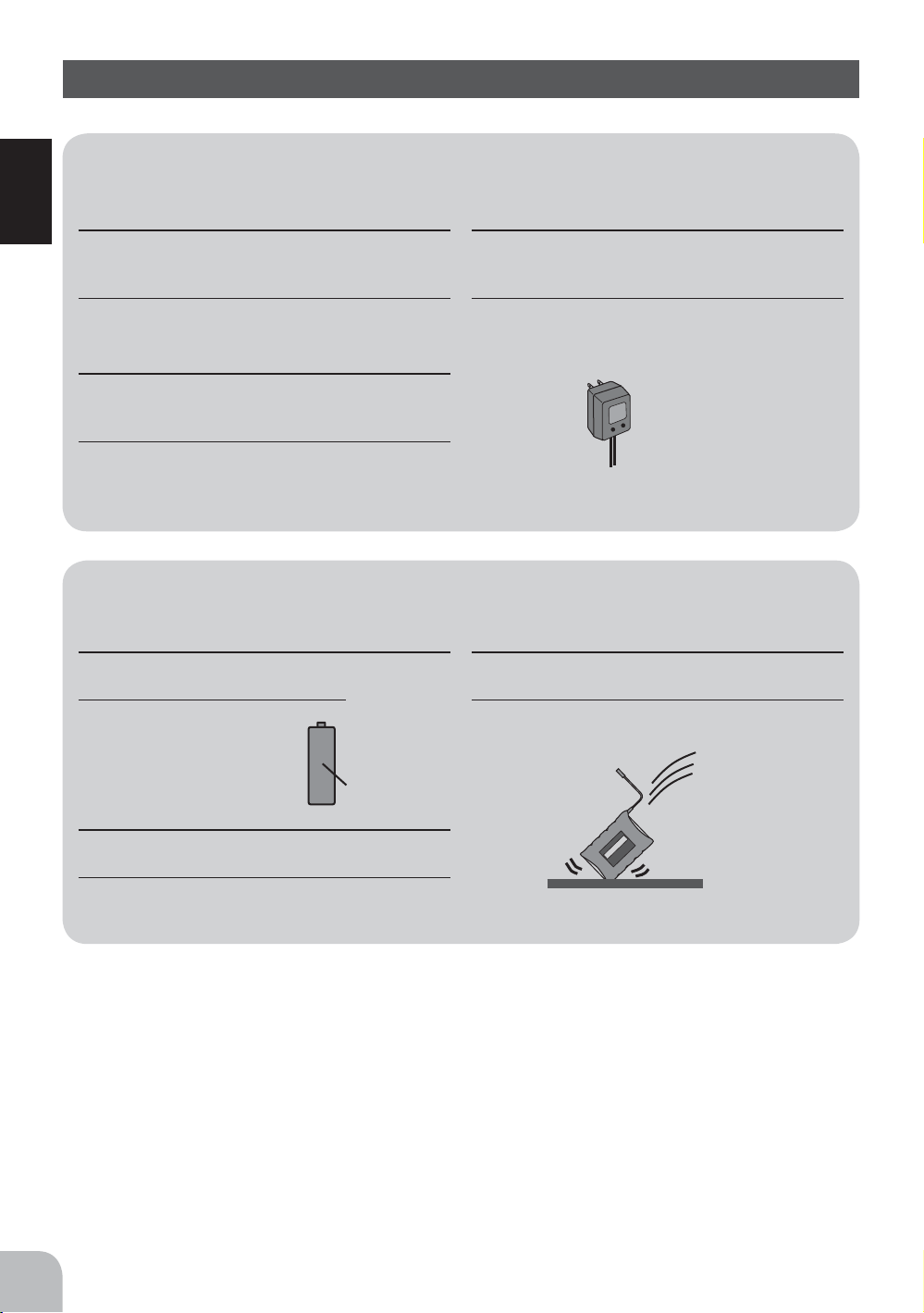
To recharge the transmitter NiCd,
j
use the special charger made for this
purpose.
Overcharging could cause the NiCd battery to overheat,
leak or explode. This may lead to fire, burns, loss of
sight and many other types of injuries.
j
––––––––––––––– Prohibited Procedures –––––––––––––––
Do not use commercial AA
l
size NiCd batteries.
Quick charging may cause the
battery contacts to overheat and
damage the battery holder.
l
Use
prohibited
Do not drop the NiCd battery or expose
l
it to strong shocks or vibrations.
The battery may short circuit and overheat, electrolyte
may leak out and cause burns or chemical damage.
Do not short circuit the NiCd battery
l
terminals.
Causing a short circuit across the battery terminals may
cause abnormal heating, fire and burns.
8
NiCd AA size
batteries.
l
Page 8
9
For Your Safety As Well As That Of Others
Warning
n
Storage and Disposal Precautions
–– Prohibited Procedures ––
Do not leave the radio system or
l
models within the reach of small
children.
A small child may accidentally operate the system. This
could cause a dangerous situation and injuries. NiCd
batteries can be very dangerous when mishandled and
cause chemical damage.
Do not throw NiCd batteries into a
l
fire. Do not expose NiCd batteries to
extreme heat. Also do not disassemble or
modify a NiCd battery pack.
Overheating and breakage will cause the electrolyte to
leak from the cells and cause skin burns, loss of sight as
well as other injuries.
<NiCd Battery Electrolyte>
The electrolyte in NiCd batteries is a strong alkali. Should you get even
the smallest amount of the electrolyte in your eyes, DO NOT RUB. Wash
immediately with water and seek medical attention at once. The electrolyte can
cause blindness. If electrolyte comes in contact with your skin or clothes, wash
with water immediately.
–– Mandatory Procedures ––
When the system will not be used for
j
any length of time store the system
with batteries in a discharged state. Be sure
to recharge the batteries prior to the next
time the system is used.
If the batteries are repeatedly recharged in a slightly
discharged state the memory effect of the NiCd battery
may considerably reduce the capacity. A reduction in
operating time will occur even when the batteries are
charged for the recommended time.
Caution
n
–– Prohibited Procedures ––
Do not store your R/C system in the
l
following places.
- Where it is extremely hot or cold.
- Where the system will be exposed to direct sunlight.
- Where the humidity is high.
-Where vibration is prevalent.
-Where dust is prevalent.
-Where the system would be exposed to steam and
condensation.
Storing your R/C system under adverse conditions
could cause deformation and numerous problems with
operations.
<NiCd Battery Recycling>
A used NiCd battery is valuable resource. Insulate the battery terminals and
dispose the battery by taking it to a battery recycling center.
–– Mandatory Procedures ––
If the system will not be used for a long
j
period of time remove the batteries
from the transmitter and model and store in a
cool dry place.
If the batteries are left in the transmitter electrolyte may
leak and damage the transmitter. This applies to the
model also. Remove the batteries from it also to prevent
damage.
Page 9

Caution
n
Other Precautions
–– Prohibited Procedures ––
Do not expose plastic parts to fuel,
l
For Your Safety As Well As That Of Others
motor spray, waste oil or exhaust.
The fuel, motor spray, waste oil and exhaust will
penetrate and damage the plastic.
–– Mandatory Procedures ––
Always use only genuine Futaba
j
transmitters, receivers, servos, FET
amps (electronic speed controls),NiCd
batteries and other optional accessories.
Futaba will not be responsible for problems caused by
the use of other than Futaba genuine parts. Use the
parts specified in the instruction manual and catalog.
10
Page 10

Before Using
Set Contents
$IWHU RSHQLQJ WKH ER[ ¿UVW FKHFN LI WKH FRQWHQWV FRQIRUP WR WKH IROORZLQJ 7KH
contents depend on the set as shown below.
Transmitter
Receiver
Servo
ESC
Receiver battery holder w/switch
Miscellaneous
If any of the set contents are missing, or you have any questions, please contact the
dealer where the unit was purchased.
S3003 (x3) S3003 (x2)
––––– MC230CR
T4GWD
R124H
–––––
Shift gate
Throttle ratchet plate
Instruction manual
Before Using
Caution
n
Always use only genuine Futaba transmitter, receiver, servo, NiCd battery and other
j
optional parts.
Futaba will not be responsible for damage caused by other than genuine Futaba parts and components. Use only the
genuine Futaba parts and components listed in the instruction manual and catalog.
11
Page 11
Before Using
Shift gate
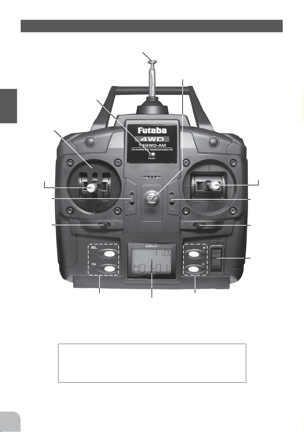
Transmitter T4GWD
Antenna
Neck strap hook
Pilot lamp
Throttle
/Shift
stick
Throttle
trim
(DT2)
Shift
trim
(DT4)
Edit keys
LCD screen
Edit keys
Aux. ch
/
Steering
stick
Aux. ch
trim
(DT3)
Steering
trim
(DT1)
Power
switch
12
Precautions when turning the power switch on and off.
When the data was changed using the edit keys or trim levers,
wait at least two seconds before turning off the power. If the
power is turned off within two seconds after the data was
changed, the new data will not be written to memory.
Page 12

13
Before Using
Digital Trim Operation (DT1/DT2/DT3/DT4)
Push the lever to the left or right (up or down).
The current position is displayed on the LCD screen for about three seconds when
each digital trim is operated.
DT2
DT4
Steering trim
position
- Each step is indicated by a tone.
- When the trim exceeds the maximum trim adjustment range, the tone will change
pitch and the lever will not move any farther.
Throttle trim
position
DT3
DT1
Aux. ch trim
position
Shift trim
position
Trim Operation
With the digital trim feature, trim adjustments have no effect on the maximum
servo travel. This prevents the linkages from binding when adjustments are made.
Page 13

Stick Lever Head Adjustment
The length of the lever head of the steering and throttle sticks can be adjusted.
Adjustment
1
2
lever head “A” clockwise and lever head “B”
counterclockwise.
Before Using
Modification To Ratchet System
When modifying the throttle stick from self-neutral system (factory installation) to
ratchet system, use the accessory parts to change the system.
Modification
Unlock lever head “A” by turning it
counterclockwise.
Adjust the head to the length best for
you, then lock the heads by turning
Lever head
“A”
Lever head
“B”
Turn off the power to the transmitter.
1
Remove the four transmitter rear case
2
screws and remove the rear case.
Disconnect the battery connector.
3
Remove the swing arm and spring. This
4
frees the throttle stick.
Install the accessory ratchet plate with
5
the screw.
At the end of modification, connect the
6
battery connector and close the rear
case.
Swing arm
and spring
Ratchet plate
and screw
Ratchet
plate
14
Swing
arm
Page 14

15
Before Using
Battery Replacement (for dry cell battery system)
Load the eight batteries in accordance with the polarity markings on the battery
holder. (8 AA Size Batteries)
Battery Replacement
Caution
n
Remove the battery cover
1
from the transmitter by
sliding it in the direction of the
arrow in the figure.
Always be sure you reinsert the bat-
j
teries in the correct polarity order.
If the batteries are loaded incorrectly, the transmitter
may be damaged.
Remove the used batteries.
2
Load the new AA size
3
batteries. Pay very close
attention to the polarity markings
and reinsert accordingly.
Slide the battery cover back
4
onto the case.
When the transmitter will not be used
j
for any short or long period of time,
always remove the batteries.
If the batteries do happen to leak, clean the battery
case and contacts thoroughly. Make sure the contacts
are free of corrosion.
Check:
Turn the power switch on the
transmitter to the ON position. Check
the battery voltage display on the LCD
screen.
If the voltage is low, check the
EDWWHULHVIRULQVXI¿FLHQWFRQWDFWLQ WKH
case or incorrect battery polarity.
Low Battery Alarm:
If the transmitter battery voltage drops
below 8.5V an alarm will sound and
"LOW BT" will be displayed on the
LCD screen.
The low battery alarm is meant to be
a safety feature only. Do NOT operate your radio below 9V. Always shut
your radio off as soon as possible after
the low battery warning tone to avoid
loss of control.
Page 15

Charging The Battery (for NiCd battery system)
Special
Chager
NiCd battery
NT8F700B
- Always use an NT8F700B NiCd battery.
Before Using
Charging the NiCd Battery
1
charging jack on the side of the
transmitter.
2
3
When charging the NT8F700B NiCd battery with the special charger, allow about
15 hours for charging. If the transmitter has not been used for some time, cycle the
battery by charging and discharging it two or three times.
Charging
jack
Plug the transmitter cord of
the special charger into the
Plug the charger into an AC
outlet.
Check that the charging LED
lights.
AC outlet
Charger
Transmitter charging
LED
Cord to transmitter
charging jack
16
Warning
n
Never plug it into an outlet other than
l
indicated voltage.
Plugging the charger into the wrong outlet may result in
an explosion, sparking, or fire.
Always use the special charger or a
j
quick charger for digital proportional
R/C sets to charge a digital proportional R/C
set NiCd battery.
Overcharging a NiCd battery can result in burns, fire,
injuries, or loss of sight due to overheating, breakage, or
electrolyte leakage.
Do not insert and remove the charger
l
when your hands are wet.
It may cause an electric shock.
j
Page 16

17
Before Using
Caution
n
Never try to recharge a dry cell battery.
l
The transmitter may be damaged or the battery
electrolyte may leak or the battery may break.
When the charger is not in use, discon-
j
nect it from the AC outlet.
Do this to prevent accidents and to avoid overheating.
Set Data Backup
The set data of each function of the T4GWD transmitter is stored in a memory
element that does not require a backup battery. Therefore, the T4GWD transmitter
can be used without paying attention to the backup battery life.
Page 17

For the receiver, servos, and other connections, see page 19.
For the installation precautions, see page 20.
Before Using
Servo lead
Antenna
Receiver
R124H receiver
Servo
Servo horn
Crystal
When changing the frequency, use the
specified Futaba crystal set.
Connectors
4: Shift servo (CH4)
3: Aux. Ch (CH3)
2: Throttle servo (CH2)
1: Steering servo (CH1)
B: Power connector
Mounting flange
For the receiver, servos, and other connections, see page 19.
For the installation precautions, see page 20.
E.S.C.
Applicable motors (Number of turns is criteria.)
•Use the MC230CR with a motor with 20T or more turns.
*If a motor with a number of turns smaller than the above is used, the heat
protector and overcurrent protection circuit may operate. The number of turns
of the motor is a criteria only. Depending on the running conditions, the
protection circuit may operate even if the condition above is satisfied.
Checker LED
Pushbutton
switch
(Orange)
(Blue)
(Black)
(Red)
MC230CR
Receiver connector
Connects to the receiver throttle channel.
Motor connector
Connects to the motor.
(Orange) is positive. (Blue) is negative.
If the motor rotates in the wrong
direction, interchange the connections of
this connector.
Nicd battery connector
Connects to the running Nicd battery.
(Red) is positive. (Black) is negative.
NiCd battery 6~7 cells (7.2~8.4V)
18
Power switch
Miniature screwdriver
Accessory. Use to press the
pushbutton switch.
Page 18

Installation
Receiver and Servo Connections
When connecting and installing the receiver and servos, read the "Installation
Safety Precautions" on the next page.
Installation For Gas Powered Models
Receiver
Power
*Rubber band
switch
Battery holder
Installation When MC230CR Is Used
(B)
(CH4)
(CH2)
(CH1)
Shift servo
Throttle servo
Steering servo
Installation
To motor connectors
To battery connector
MC230CR
Receiver
(CH2)
Power switch
(CH4)
(CH1)
Shift
servo
Steering servo
19
Page 19

Warning
n
Installation Safety Precautions
Connector Connections
Be sure the receiver, servo, crystal and
j
connectors are fully and firmly con-
nected.
If vibration from the model causes a connector to work
loose while the model is in operation, you may lose
control .
Receiver Vibration Damping and
Waterproofing
(Car): Dampen the vibration to the
j
receiver by mounting to the chassis or
mounting plate with thick double sided tape
in electric powered models. In gas powered
models wrap the receiver in foam and mount
it where the vibration is the least prevalent.
Installation
(Boat): Dampen the vibration to the
j
receiver by wrapping it in foam. Waterproof by placing it in a plastic bag or watertight the radio box in your model.
If the receiver is subjected to strong vibration or shock
erratic or loss of control may occur. If any moisture
comes in contact the receiver and servos you may
experience the same result as well as damage to the
system.
Receiver Antenna
Do not cut or bundle the receiver an-
l
tenna.
Do not bundle the receiver antenna to-
l
gether with the servo lead wires.
Keep the receiver antenna at least 1
j
inch away from the motor and battery
and wires that handle heavy current loads.
Cutting, bundling or routing the receiver antenna near
any device that produces noise will reduce the operating
range of the system and result in loss of control.
Also route the receiver antenna away from metal, carbon
¿EHUDQG RWKHUSDUWVWKDWFRQGXFWHOHFWULFLW\7KHVHSDUWV
can transmit high frequency noise.
Servo Throw
Operate each servo over its full stroke
j
and be sure the linkage does not bind
or is loose.
The continuous application of unreasonable force to a
servo may cause damage and excessive battery drain.
Servo Installation
When you install the servos always use
j
the rubber grommets provided in servo
hardware bags. Mount the servos so they do
not directly come in contact with the mount.
If the servo case comes in direct contact with the mount,
vibration will be directly transmitted to the servo. If this
condition continues for a long time the servo may be
damaged and control will be lost.
Motor Noise Suppression
Always install capacitors to suppress
j
noise when electric motors are used.
If capacitors are not properly installed you could
experience erratic operation and reduced range as well
as loss of control.
Other Noise Suppression Methods
Be sure there are no metal parts in
j
your model which under vibration could
come in contact with other metal parts.
Metal to metal contacts under vibration will emit a
high frequency noise that will affect the receiver's
performance. You could experience erratic operation and
reduced range as well as loss of control.
20
Electronic speed control
Install the heat sinks where they will not
j
come in contact with aluminum, carbon
fiber or other parts that conduct electricity.
If the E.S.C. (Electronic speed control) heat sinks touch
other materials that conduct electricity a short circuit
could occur. This could result in loss of control and
damage to the system.
Page 20

Initial Set-Up
Preparations
Before setting the transmitter functions, check and set items below:
Display when power switch is turned on
Turn on the transmitter power.
Battery voltage
Model numberModel name
Digital Trims Initial Set-Up
Operate the DT1-DT4 levers and check if each trim value on the screen changes.
After checking each trim, set the trim value to the center (0) position.
Steering trim
position
Throttle trim
position
Aux. ch trim
position
Shift trim
position
Set-Up Procedure When Installed In a Car
When installing the servos in a car, performing function set-up in the following
order is recommended.
Set up the servo trims: see the above mentioned "Digital Trims Initial
1
Set-Up".
Set the servo direction of operation using the Reverse function: see p.
2
27.
*The servo installation method and linkage direction depend on the kit. Therefore, the servo operation
direction may have to be reversed relative to transmitter operation. Before installing the servo, check the
operating direction and set it using the Reverse function.
Set the subtrim and adjust the servo neutral point: see p. 26.
3
Initial Set-Up
Set EPA of each channel and adjust the servo throw (travel): see p. 24.
4
21
Page 21

MC230CR Set-Up Procedure
NEUTRAL, HIGH, AND BRAKE MAX POINTS SETTINGS
Set the steering angle adjustment function (EPA) to
100% and the ABS function and acceleration function
to OFF using the transmitter throttle channel function.
If the steering angle is too large or the ABS and acceleration
functions are on, erroneous operation may occur.
*When using the ABS function, after setting up
the MC230CR, stop the reverse function, then
turn on the ABS function. If the ABS function is
on, the MC230CR cannot be set up correctly.
Before setting each point, set the transmitter throttle channel trim to neutral.
Turn on the power in transmitter -> amp order.
1
Transmitter throttle operation
(Pushbutton switch operation) (Checker LED)
MC230CR
2
Neutral point
setting
・Neutral state
㨯Press the pushbutton switch.
(0.5 secs or longer)
(Confirmation beep sounds)
㨯Continuous single blink
3
High point
setting
・Full high state
㨯Press the pushbutton switch.
(Confirmation beep sounds)
㨯Continuous double blink
4
Brake MAX
Initial Set-Up
point setting
* Since the data is read at the end of setting of all points, the points cannot be set independently.
* If the amp power was turned off during setting, the setting points cannot be memorized. (The previous settings are retained.)
* The confirmation beep sounds only when the motor was connected.
・Full brake state
㨯Press the pushbutton switch.
(Confirmation beep sounds.)
㨯If the LED goes out,
setting is complete.
If the LED does not go off
but blinks rapidly, setting
was not performed
normally. Repeat setting
from "Neutral point
setting".
㨯Continuous rapid blink
22
Page 22

Function Map
Power switch turned on
Press "SEL" key to select the desired
function screen.
Press it for one second or more to
scroll to the opposite direction.
(Initial Screen)
Press "CH" key to select the
next set-up screen.
End Point Adjuster
Subtrim
Channel Reverse
Model Select
Model Copy
Model Reset
Model Name
Function Map
23
Page 23

Functions
End point adjuster/EPA
Use this when performing left and right steering angle adjustments, throttle high
side/brake side operation amount adjustment, channel 3 servo up side/down side
operation amount adjustment, and shift servo left side/right side operation amount
adjustments during linkage.
- Corrects the maximum steering angle and left and right steering angles when there is a difference in the turning
radius due to the characteristics, etc. of the vehicle.
Maximum steering angle
The EPA function basically determines the maximum steering angle of each
channel. The Sub trim function may have been adjusted, or the operating range
set by EPA function may be exceeded. Check the linkage each time the Sub trim
function is adjusted.
Warning
n
Calling the setup screen
(Initial screen)
Functions
Press "SEL" key to select the
desired function screen.
Make sure that unreasonable force is not applied to the
j
servo horn during each channel operation.
If unreasonable force is applied to the servo horn, the servo may malfunction
and the model may run out of control.
Press "CH" key to select the next set-
(Setup screen)
[Setup items]
C1-L.F.U : Steering (left side)
C1-R.B.D : Steering (right side)
C2-L.F.U : Throttle (forward side)
C2-R.B.D : Throttle (brake side)
C3-L.F.U : 3rd channel (up side)
C3-R.B.D : 3rd channel (down side)
C4-L.F.U : Shift (left side)
C4-R.B.D : Shift (right side)
up screen.
[Adjustment range]
0~120% (each channel, each direction)
Initial value: 100%
[Adjustment buttons]
- Use the (+) and (-) keys to make
adjustments.
- Return to the initial value by pressing
the (+) and (-) buttons simultaneously
(approx. 1 sec).
24
Page 24

25
Functions
Steering (EPA) adjustment
(Preparation)
- Select setup item "C1" and make the following adjustments:
Steering (left side) adjustment
1
Turn the steering stick fully to the left and use the (+) and (-) buttons to
adjust the steering angle.
Steering (right side) adjustment
2
Turn the steering stick fully to the right and use the (+) and (-) buttons to
adjust the steering angle.
When adjusting the EPA of another channel immediately after this, select
3
the setup item ("C2", "C3" or "C4") and then adjust the operation amount.
When ending adjustment, return to the initial screen by pressing the (SEL)
button.
Throttle (EPA) adjustment
(Preparation)
- Select setup item "C2" and make the following adjustments:
Throttle (forward side) adjustment
1
Push the throttle stick fully to the high side and use the (+) and (-) buttons
to adjust the operation amount. However, when using an ESC, set to
100%.
Throttle (brake side/reverse side) adjustment
2
Pull the throttle stick fully to the brake side and use the (+) and (-) buttons
to adjust the operation amount. However, when using an ESC, set to
100%.
When adjusting the EPA of another channel immediately after this, select
3
the setup item ("C1", "C3" or "C4") and then adjust the operation amount.
When ending adjustment, return to the initial screen by pressing the (SEL)
button.
Repeat this procedure for the end point settings on the other channel
remaining ("C3" and "C4".)
Page 25

Subtrim / SBT
Use this function to adjust the neutral position of the
steering, throttle, channel 3 and shift servos.
Subtrim shifts the entire servo travel range in the set direction.
Calling the setup screen
(Initial screen)
Press "SEL" key to select the
desired function screen.
(Setup screen)
[Setup Item]
SBT-C1 : Steering
SBT-C2 : Throttle
SBT-C3 : Channel 3
SBT-C4 : Shift
ࡦ࠲ࠍߔߚa
ߦ↪ߔࠆa
Use to adjust the neutral position
Press "CH" key to select the next setup screen.
[Subtrim position]
-100%(L.F.U)~0~+100%(R.B.D)
Initial value: 0%
[Adjustment buttons]
- Use the (+) and (-) buttons to make
adjustments.
- Press the (+) and (-) buttons
simultaneously (approx. 1 sec) to
return to the initial screen.
Subtrim adjustment
(Preparation)
-Set the steering, throttle, channel 3, and shift digital trims to the neutral "0"
position.
- Preselect setup channel "C1", "C2", "C3" or "C4".
(Subtrim adjustment)
1
Functions
Use the (+) or (-) button to adjust the center.
(Each channel can be set similarly.)
When ending adjustment, return to the initial screen by pressing the (SEL)
2
button.
26
Page 26

27
Functions
Servo Reverse / REV
This function reverses the direction of operation of the servos related to transmitter
steering, throttle, channel 3 and shift operation.
However, when the position set by trim or subtrim shifts from the center, the center
becomes the opposite side.
Calling the setup screen
(Initial screen)
Press "SEL" key to select the
desired function screen.
(Setup screen)
[Setup Item]
REV-C1 : Steering
REV-C2 :Throttle
REV-C3 : Channel 3
REV-C4 : Shift
Press "CH" key to select the next setup screen.
[Servo direction]
OFF: Normal side
ON: Reverse side
Servo Reverse Function Setting
(Preparation)
- Preselect setup channel "C1", "C2", "C3" or "C4".
(Servo reverse setting)
1
Use the (+) or (-) button to reverse the servo operation direction.
(Each channel can be set similarly.)
When ending adjustment, return to the initial screen by pressing the (SEL)
2
button.
Page 27

Model Select / SEL
Use this function to call a new model number, or to change a set model number, to
set new model data. The T4GWD transmitter can store the model data for three R/C
cars.
Calling the setup screen
(Initial screen)
Press "SEL" key to select the
desired function screen.
(Setup screen)
Model number
Model name
Press "CH" key to select the next setup screen.
Model Select
Model No. selection
1
Use the (CH) button to select the model No.
Select execution
2
Press the (+) and (-) buttons simultaneously for about 1 second.
When ending adjustment, return to the initial screen by pressing the (SEL)
3
button.
Functions
28
Page 28

Model Copy / CPY
This function copies the entire contents of the currently called model memory to
another model memory.
Calling the setup screen
(Initial screen)
Press "SEL" key to select the
desired function screen.
(Setup screen)
Current model No.
Press "CH" key to select the next setup screen.
Copy destination model No.
Model Copy
Copy destination selection
1
Use the (CH) button to select the copy destination model No.
Copy execution
2
Press the (+) and (-) buttons simultaneously for about 1 second.
When ending model copy, return to the initial screen by pressing the (SEL)
3
button.
Functions
29
Page 29

Model Reset / CLR
This functions resets the contents of the currently called model memory to the
initial value.
Calling the setup screen
(Initial screen)
Press "SEL" key to select the
desired function screen.
(Setup screen)
Current model No.
Model Reset
Reset execution
1
Press the (+) and (-) buttons simultaneously for about 1 second.
When ending model reset, return to the initial screen by pressing the (SEL)
2
button.
Functions
30
Page 30

31
Functions
Model Name / NAM
This function allows you to assign a three character name to each model memory.
(Number and alphabet can be used.)
Calling the setup screen
(Initial screen)
Press "SEL" key to select the
desired function screen.
(Setup screen)
Model name
Press "CH" key to select the next setup screen.
Model Name
Move the cursor (blinking) to the column you want to change using the
1
(CH) button.
Change the character using the (+) or (-) button.
2
(Set the model name by repeating steps 1 and 2 above. )
When ending model name setting, return to the initial screen by pressing
3
the (SEL) button.
Page 31

MC230CR Function
CANCELLING THE REVERSE FUNCTION
The amp reverse function can be cancelled by the following method so that the model can be used even in races
that prohibit reverse running. (Brake operation only)
(Pushbutton switch operation) (Power switch)
1
Reverse
function
cancellation
While pressing
the pushbutton switch,
BRAKE/REVERSE OPERATING INSTRUCTIONS
Operation can be switched to reverse operation by returning the throttle stick from the brake position to the neutral
position.
PROTECTION CIRCUIT OPERATION
The following protection circuits are built into the MC230CR. When a protection circuit operates, remove the
cause before operating the model again.
Overcurrent
protection
Heat protector
Low voltage
operation
MC230CR
*When desired, you can enable the cancelled reverse
function by repeating the operation shown at the left.
ON
set the power switch to ON.
When an overcurrent flows due to an output short circuit, etc., the overcurrent protection circuit automatically
limits the current to protect the FET.
Remove the cause of the short circuit, etc. before operating the model again.
When abnormal heating of the FET due to an overload, etc. is detected, the heat protector operates so that
the speed is gradually reduced.
When the FET temperature drops, the heat protector automatically resets. However, remove the cause
of the overheating before operating the model again.
When the Nicd battery voltage drops, this function limits the motor output current and ensures steering operation.
After the speed drops, immediately recover the vehicle.
(The reverse function is switched alternately.)
CHECKER LED DISPLAY
The amp operates linearly in proportion to the amount of forward, reverse, and brake operation. The amp operating
state can be checked with the checker LED as shown below.
Operation
Amp power ON
High point
Functions
Forward
Neutral point
Reverse
/brake
Brake MAX point
(Amp power left on alarm)
When the transmitter power
was turned off first.
* Confirmation beep only sounds when the motor was connected.
(Reverse operation set)
Single blink
(Single confirmation beep)
(Only brake operation set)
Double blink
(Two confirmation beeps)
Blinks. (Confirmation
beep also sounds.)
Checker LED display
Off
*Becomes brighter nearer the high
On
point.
Off
On
*Becomes brighter nearer the brake
MAX point.
Off
*Not used with PCM receivers.
*When the transmitter is OFF, this function is
not performed in environments such that the
servo operates erroneously. Not sure what
this is supposed to mean in yellow.
32
Page 32

Reference
Ratings
*Specifications and ratings are subject to change without prior notice.
Transmitter T4GWD
(2 Stick system, 4 channels)
- Transmitting frequencies: 27, 29,
40, 41 or 75MHz band
- Modulation: AM
- Power requirement:
(Dry cell battery)
Penlight x 8 (12V)
(NiCd battery)
NT8F700B NiCd battery (9.6V)
- Current drain: 250mA or less
Receiver R124H
(4 channels, AM receiver)
- Receiving frequencies: 27, 29, 40,
41 or 75MHz band
- Intermediate frequency: 455kHz
- Power requirement:
4.8 or 6.0V (shared with servos)
- Current drain: 5mA (at 4.8V)
- Size: 25.6x37.7x15.3mm
(1.00x1.48x0.60in.)
- Weight: 14.8g (0.52oz.)
E.S.C. MC230CR
(Electronic speed control)
- Operating system: Forward, reverse,
and brake operations are all linear.
- Power requirement: Nicd battery
6-7 cells (7.2 to 8.4V)
3:0IUHTXHQF\N+]¿[HG
- Setting: One-touch input by
pushbutton switch. Set data is
saved to built-in EEPROM.
- Current capacity (FET rating):
Forward=90A, reverse=45A
- Size: 27.1x33.3x12.8mm
(1.07x1.31x0.50in.)
(excluding protruding parts)
- Silicon cord gauge size:
AWG16 equivalent
- Weight: 44g (1.55oz.)
(including connectors and switches)
- BEC voltage: 6.0V
Servo S3003
(standard servo)
- Power requirement: 6V
(common with receiver)
- Current drain: 8mA (at 6V / Idle)
- Output torque: 4.1kg-cm (57in.-oz.)
at 6V
- Operating speed: 0.19sec/60 degree
at 6V
- Size: 40.4x19.8x36mm
(1.59x0.78x1.42in.)
- Weight: 37.2g (1.31oz.)
Reference
33
Page 33

Optional Parts
The following parts are available as 3GR options. Purchase them to match your
application. For other optional parts, refer to our catalog.
Crystal
<Type of Crystal>
There are crystals for FM and AM, depending on the modulation mode, and
crystals for single conversion and dual conversion, depending on the receiver
circuitry. Use AM crystal sets with R124H.
Warning
n
Use only genuine Futaba crystal.
j
The use of other than Futaba crystal will result in decrease of range
as well as loss of control.
Transmitter NiCd Battery
When purchasing a transmitter NiCd battery as a spare, etc., use the following:
Part name: NT8F700B
Reference
(9.6V/700mAh)
34
Page 34

35
Reference
Troubleshooting
If your system fails to operate or you experience a short range problem or erratic
control, check the table below for possible causes. If after you have followed the
suggestions listed, the problem is not corrected, return the system to our service
department for inspection, and repair.
(Item Check)
Transmitter
Battery
Dead battery -> Change the batteries. Charge the NiCd
Batteries inserted incorrectly. -> Reload the batteries in accordance with the polarity markings
Faulty contact -> Check to see if the contacts are bent and not making good contact
Dirty contacts -> Clean the contacts and check for corrosion.
Antenna
Loose -> Be sure the antenna is screwed in tightly
Not fully extended -> Fully extend the antenna
Receiver
Battery
Dead battery -> Replace or recharge
Wrong polarity -> Check connections
Antenna
Near other wiring -> Move away from wiring
Was antenna cut -> Request repair
Is the antenna bundled or coiled -> Keep the antenna straight and as much in the air as possible
Crystal
Loose -> Push in firmly
Wrong brand -> Be sure the frequencies match in transmitter and receiver
Connector connections
Wiring incorrect -> Insert all connectors firmly
Loose connections -> Push the connector in firmly
Linkage
Binding or loose -> Adjust the linkage in model
Is movement stiff -> Adjust linkage in model
Motor (Electric powered)
Noise problems -> Install capacitors on motor
Page 35

Error Displays
Low Battery Alarm
If the transmitter battery voltage drops to 8.5V or less, an audible alarm will sound
and "LOW BT" will be displayed on the LCD screen.
LCD screen:
Warning
n
When a low battery alarm is gener-
j
ated, cease operation immediately
and retrieve the model.
If the battery goes dead while in operation, you will
Audible alarm:
Continuous tone.
Backup Error
lose control.
If the data is lost for an unknown reason, an audible alarm will sound and "BCK UP
" will be displayed on the LCD screen.
LCD screen:
Reference
Audible alarm:
Tone will sound (9 times), then
repeat.
Warning
n
When a backup error is generated,
j
immediately stop using the system
and request repair from the Futaba Service
Center.
If you continue to use the system, the transmitter may
malfunction and cause loss of control.
36
Page 36

37
Reference
When requesting repair
Before requesting repair read this instruction again recheck your system. Should the
problems continue request as follows.
(Information needed for repair)
Describe the problem in as much detail as possible and send the letter along with
the system in question.
- Symptom (Including the conditions and when the problem occurred)
- R/C System (Send transmitter, receiver and servos)
- Model (Type of model, brand name and model number or kit name)
- Detailed packing list (Make a list of all items sent in for repair)
- Your name, address and telephone number.
(Warranty)
Read the Warranty card.
- When requesting warranty service, send the card or some type of dated proof
purchase.
Hobby Services (U.S. only)
3002 N. Apollo Drive, Suite 1
Champaign, IL 61822 U.S.A.
Phone: (217) 398-0007
service@futaba-rc.com
Makuhari Techno Garden Bldg., B6F 1-3 Nakase, Mihama-ku, Chiba 261-8555, Japan
Phone: (043) 296-5119 Facsimile: (043) 296-5124
FUTABA CORPORATION
©FUTABA CORPORATION 2007, 8 (1)
 Loading...