

Page 1
15" MULTI-COLOR HIGH-PERFORMANCE
Back
SHIPBORNE RADAR AND ARPA
FR-1500 MARK-3 SERIES
Page 2

Thepaperusedinthismanual
9-52 Ashihara-cho,9-52 Ashihara-cho,
A
A
*
0
*
0
*
0
*
0
*
O
*
O
*
O
*
O
Nishinomiya 662-8580, JAPANNishinomiya 662-8580, JAPAN
Telephone :Telephone : 0798-65-21110798-65-2111
FaxFax 0798-65-42000798-65-4200
ll rights reserved.
ll rights reserved.
(( TATATATA ))
::
Pub. No.Pub. No. OME-34500OME-34500
FR-1500 MARK-3 SER.FR-1500 MARK-3 SER.
Printed in JapanPrinted in Japan
Your Local Agent/Dealer Your Local Agent/Dealer
IRST EDITION :
IRST EDITION :OCTOCT.. 19981998
V7V7 :: APRAPR.. 21, 200521, 2005
0080840401*
0080840401*
0080840401*
0080840401*
* 0 0 0 8 0 8 4 0 4 0 1 ** 0 0 0 8 0 8 4 0 4 0 1 *
iselementalchlorinefree.
ME34500V70*
ME34500V70*
ME34500V70*
ME34500V70*
* O M E 3 4 5 0 0 V 7 0 ** O M E 3 4 5 0 0 V 7 0 *
Page 3
SAFETY INSTRUCTIONS
DANGER
Before turning on the radar/ARPA, make sure that there is not one near the
antenna unit. Serious injury or even death may result if a rotating antenna strikes
someone standing nearby.
WARNING
Radio frequency Radiation Hazard
The radar antenna emits electromagnetic radio frequency (RF) energy, which can
be harmful, particularly to your eyes. Never look directly into the antenna aperture
from a close distance while the radar is in operation or expose yourself to the
transmitting antenna at a close distance.
SOFTWARE PROGRAM NO.
Model Software (Prog No.) Date
0359152109 March 00
FR-1500 MARK-3
ATA
RP-17 0359155103 March 00
0359152110 Dec. 01
0359152111 June 04
1859041102 June 99
1859042101 June 99
RP-180
0359219-01
0359220-01
June 04
i
Page 4
For your safety:
WARNING
Do not open the equipment
Hazardous voltage which can cause electrical shock exists inside the equipment.
Only qualified personnel should work inside the equipment.
Turn off the radar power switch before servicing the antenna unit. Post a
warning sign near the switch indicating it should not be turned on while the
antaean unit is being serviced.
Prevent the potential risk of being struck by the rotating antenna and exposure to
RF radiation hazard.
Wear a safety belt and hard hat when working on the antenna unit.
Severe injury or death can result if someone falls from the radar antenna mast.
Do not disassemble or modify the equipment.
Fire, electrical shock or serious injury can result.
Turn off the power immediately if water leaks into the equipment or the
equipment is emitting smoke or fire.
Continued use of the equipment can cause fire or electrical shock.
WARNING
Do not place liquid-filled containers on the top of the equipment.
Fire or electrical shock can result if a liquid spills into the equipment.
Do not operate the equipment with wet hands.
Electrical shock can result.
Keep heater away from equipment
Heat can alter equipment shape and melt the power cord, which can cause fire or
electrical shock.
CAUTION
Do not use the equipment for other than its intended purpose.
Use of the equipment as a stepping stool, for example, can result in personal
injury or equipment damage.
Replace the monitor when the picture becomes difficult to see.
The average life of the monitor screen is about 10 years. Replace it when the
picture becomes difficult to see.
A warning label is attached to the equipment. Do not remove the label. If the
label becomes soiled or illegible, contact a Furuno agent or dealer.
No one navigation device should be solely relied on for navigation of a ship.
Always confirm position against all available aids to navigation, for safety of ship
and crew.
ii
Page 5

Compliance with MED and R&TT E Directive
This radar compiles with MED 96/98/EC and its amendment 2002/75/EC of September 2, 2002
and also complies with the R&TTE Directive 1999/5/EC. In accordance with Article 6-3 of the
above-mentioned R&TTE directive, FURUNO intends to put this radar on the market of the
following countries in EU as well other markets.
Austria, Belgium, Cyprus, Denmark, Estonia, Finland, France, Germany, Greece, Hungary, Ireland,
Italy, Latvia, Lithuania, Malta, Poland, Portugal, Slovenia, Spain, Sweden, The Netherlands, United
Kingdom, Iceland, Norway
iii
Page 6

TABLE OF CONTENTS
INTRODUCTION .........................................................................................................................................vi
Specificati on s of FR-1500 M ark- 3 S eries shipborne radar.......................................................................ix
1 OPERATIONAL OVERVIEW................................................................................................................1.1
1.1 Turning on the Power ...........................................................................................................................1
1.2 Transmitter ON.....................................................................................................................................1
1.3 Control Description...............................................................................................................................2
1.4 CRT Brilliance ......................................................................................................................................3
1.5 Control Panel Backlighting....................................................................................................................3
1.6 Tuning the Receiver..............................................................................................................................3
1.7 Degaussing the Screen ........................................................................................................................4
1.8 Initializing the Compass Readout..........................................................................................................4
1.9 Entering Own Ship’s Speed ..................................................................................................................5
1.10 On-screen Legends and Markers........................................................................................................6
1.11 Presentation Modes............................................................................................................................7
1.12 Selecting the Range Scale................................................................................................................10
1.13 Selecting the Pulselength .................................................................................................................10
1.14 Adjusting the Sensitivity....................................................................................................................11
1.15 Suppressing Sea Clutter ...................................................................................................................11
1.16 Suppressing Precipitation Clutter ......................................................................................................12
1.17 Interference Rejector ........................................................................................................................12
1.18 Measuring the Range .......................................................................................................................13
1.19 Measuring Bearing............................................................................................................................14
1.20 Collision Assessment by the Offset EBL ...........................................................................................14
1.21 Measuring Range and Bearing Between Two Targets.......................................................................16
1.22 Setting a Target Alarm Zone.............................................................................................................17
1.23 Off-centering (shift)...........................................................................................................................18
1.24 Echo Averaging................................................................................................................................19
1.25 Electronic Plotting Aid (EPA).............................................................................................................21
1.26 Target Trails (Echo Trails).................................................................................................................24
1.27 Parallel Index Lines ..........................................................................................................................27
1.28 Reference Mark (not available with Video Plotter RP-17 or RP-180)..................................................27
1.29 Zoom (R-type only)...........................................................................................................................28
1.30 Markers............................................................................................................................................29
1.31 Suppressing Second-trace Echoes ...................................................................................................30
1.32 [F1] Key............................................................................................................................................30
1.33 [F2] Key............................................................................................................................................31
1.34 FUNCTION Key................................................................................................................................32
1.35 Adjusting Brilliance of Screen Data ...................................................................................................34
1.36 Echo Stretch, Contrast, Enhanced Video ..........................................................................................35
1.37 Watch Timer.....................................................................................................................................36
1.38 Noise Rejector..................................................................................................................................37
1.39 Navigation Data................................................................................................................................37
1.40 Alarm Output (R-type only) ...............................................................................................................37
1.41 Outputting Target Position (R-type only) ...........................................................................................37
1.42 Degaussing Interval ..........................................................................................................................38
1.43 Background Color.............................................................................................................................38
1.44 Clutter Sweep...................................................................................................................................38
1.45 Day, Night Brilliance .........................................................................................................................39
1.46 Contrast............................................................................................................................................39
1.47 Radar Map (RP-17 or RP-180 required)............................................................................................40
1.48 Alarms..............................................................................................................................................44
1.49 Enlarging Close-in Targets (R-type only)...........................................................................................46
1.50 A/D Converter Curve Setting (R-type only)........................................................................................46
1.51 Echo Area (R-type only)....................................................................................................................47
iv
Page 7

1.52 Real Time Heading Up (R-type only).................................................................................................47
2 OPERATION OF AUTOMATIC TRACKING AID (ATA) ARP-17..........................................................2.1
2.1 Introduction ..........................................................................................................................................1
2.2 Criteria of Tracking ...............................................................................................................................2
2.3 Activating, Deactivating the ATA...........................................................................................................4
2.4 Entering Own Ship’s Speed ................................................................................................................5
2.5 Acquiring Targets .................................................................................................................................6
2.6 Terminating Tracking of Targets ...........................................................................................................8
2.7 Vectors True or Relative.......................................................................................................................9
2.8 Displaying Target Data .........................................................................................................................9
2.9 Past Position Display..........................................................................................................................10
2.10 Set and Drift .....................................................................................................................................10
2.11 Alarms..............................................................................................................................................11
2.12 Track Test (Simulation Display) ........................................................................................................13
2.13 Outputting Target Data .....................................................................................................................13
2.14 Diagnostic Sequence........................................................................................................................14
2.15 Factors Affecting ARPA Functions ....................................................................................................15
3 RADAR OBSERVATION......................................................................................................................3.1
3.1 General ................................................................................................................................................1
3.2 False Echoes........................................................................................................................................2
3.3 SART (Search and Rescue Transponder).............................................................................................4
3.4 RACON (Radar Beacon).......................................................................................................................6
4 OPERATION OF VIDEO PLOTTER RP-17 (OPTION).......................................................................... 4.1
5 MAINTENANCE...................................................................................................................................5.1
5.1 Periodic Maintenance Schedule............................................................................................................1
5.2 Life Expectancy of Major Parts .............................................................................................................2
5.3 Replacement of Batteries......................................................................................................................2
6 TROUBLESHOOTING.........................................................................................................................6.1
6.1 Easy Troubleshooting...........................................................................................................................1
6.2 Advanced-level Troubleshooting...........................................................................................................2
6.3 Diagnostic Test.....................................................................................................................................6
6.4 Menu Hierarchy....................................................................................................................................8
7 OPTIONAL EQUIPMENT.....................................................................................................................7.1
7.1 Performance Monitor (Option)...............................................................................................................1
8 DIGITAL INTERFACE (IEC 61162-1 E di t ion 1 and 2))........................................................................8.1
Description of Sentences......................................................................................................................3
9 PARTS LOCATION and PARTS LIST.................................................................................................9.1
9.1 ANTENNA UNIT, SCANNER OUTLINE and RF MODULE....................................................................1
9.2 Circuit diagrams....................................................................................................................................5
9.3 Parts list ...............................................................................................................................................8
Declaration o f conformity to type
v
Page 8

INTRODUCTION
Word to the Owner of FURUNO Radar
Thank you for purchasing this FURUNO radar. We are confident you will discover why FURUNO
has become synonymous with quality and reliability.
Dedicated in the design and manufacture of marine electronics equipment for half a century,
FURUNO Electric Company has gained an unrivaled reputation as a world leader in the industry.
This is the result of our technical excellence as well as our worldwide distribution and service
network.
Please carefully read and follow the safety information and operating and maintenance instructions
set forth in this manual before attempting to operate the equipment and conduct any maintenance.
Your radar set will perform to the utmost of its ability only if it is operated and maintained in
accordance with the correct procedures.
Features of Thi s Serie s of Radars
• Daylight-bright rasterscan 15-inch multi-color, high-resolution display
• New microprocessing technology with high-speed high-density gate array and software
expertise
• New cast aluminum scanner gearbox and new series of radiators
• Easy operation by combination of discrete keys, rotary controls, and menu operation, all
logically arranged and configured
• Electronic Plotting Aid (EPA) fitted standard, Automatic Tracking Aid (ATA) option exceeding
IMO and IEC standards
• Reliable CPA and TCPA warning in any plotting mode, accurate target data
• Stand-alone or integrated configuration
• Meets the current and future IMO and IEC standards as a shipborne radar. New radar standard
MSC.64(67) Annex 4 must be met for new installation on and after January 1, 1999
FR-1500 Mark-3 Series of Radars
This Series of FURUNO radars are designed to meet various customers’ needs and the exacting
requirements of international and national standards and regulations including:
- IMO A.477(XII): Performance Standards for Radar Equipment (up to 31.12.1998)
- IMO MSC.64(67) Annex 4: Performance Standards for Radar Equipment (1.1.1999 and after)
- IEC 60936-1: Shipborne Radar Operational and Performance Requirement
(1.1.1999 and after)
- IEC 60872-2: Automatic Tracking Aids (ATA)
rd
- IEC 60945: 1996-11(3
Ed) Marine Navigational Equipment General Requirements
vi
Page 9

Models
This series of radar and ARPA is available in the following models:
FR-1505 MARK-3 X-band 6 kW
FR-1510 MARK-3 X-band 12 kW
FR-1525 MARK-3 X-band 25 kW
All come with the EPA (Electronic Plotting Aid) fitted standard. An option is available to provide the
full functionality of ATA (Automatic Tracking Aid). A Video Plotter (Chart Plotter), which provides
Radar Map functions, and Performance Monitor are also optionally available.
The FR-1500 MARK-3 Series is available in the Regular type (R-type) and IMO type . The R-type
satisfies the IMO and IEC standards but includes more flexibility of functionality. These radars
comply with the carriage requirements on the relevant type of ships of the 1974 SOLAS
Convention.
The table below shows the differences between R-type and IMO-type radars. Other functions and
specifications are common. The operator cannot navigate between the two types.
Function IMO type Regular type (R-type)
Range scales 0.125, 0.25, 0.5, 0.75, 1.5, 3, 6, 12,
24, 48, 96 nm
Target Alarm
zones
ATA: One Guard Zone:
x2 Zoom Not available Available on menu
Echo colors Monochrome yellow or green in 16
Speed mode Manual, Log Manual, Log, and NAV (GPS, DGPS)
Target trail
intensity
Close-in range
enhancement
A/D curve Not available A, B, C, D
Radar:
2 Target Alarm Zones. NO. 1 TAZ:
between 3 and 6 nm in 0.5 nm depth,
NO. 2: anywhere when NO. 1 is valid.
Default GZ covers 3.5-4 nm,
adjustable between 3 and 6 nm, in 0.5
nm range depth.
tones
Not available 1, 2, 3, 4
Not available CENter ENHANCE on menu
0.125, 0.25, 0.5, 0.75, 1.5, 3, 6, 12,
24, 48, 72, 96 nm (sm, km on menu)
Radar: Target Alarm Zone:
st
1
and 2nd TAZs anywhere. Alarm can
be selected for inside (as TAZ) or
outside (as off-zone Anchor Watch).
ATA: One Guard Zone:
Anywhere
Choice of monochrome in 16 tones or
3 colors depending on echo strengths
vii
Page 10

When the gyrocompass or magnetic compass is not connected to IMO type radar, the functions
mentioned below are inoperative.
In this case, the HDG SNSR on the SET UP 2 menu of the Installation menu should be set to OFF.
(See page 5-7 in the installation manual.)
1. Alert and indication for heading sensor do not appear on the screen and also the indication
of HDG does not appear on the screen.
2. The PLOT on the main menu is not accessible. Therefore, the menus of EPA and ATA are
not accessible.
3. On the menu of "FUNC1 SET", "FUNC2 SET" and "FUNC3 SET", the ECHO AVG is not
available. However, echo averaging can be turned on without gyrocompass connection by
setting ECHO AVG ON on the OTHER menu of the Installation menu.
4. On the F
•2 MENU, the following are inoperative.
2. TRAIL MODE
15. PLOT MENU
16. MARK MODE
18.DRIFT MENU
26. EXT WP
30. EBL/+/PI
5. MODE on the TGT TRAIL menu is not accessible. The mode of target trail is always
relative.
6. SET & DRIFT on the OTHER menu is not accessible.
7. DEGS DEG on the DEGAUSS menu is not accessible.
8. EXT WPT on the NAV DATA menu is not accessible.
9. The MODE key is not accessible. The display mode is fixed to heading-up mode.
10.EBL/+/PI on the EBL/VRM/+ menu is not accessible.
11.HDG SET on the OTHERS menu is not accessible.
12.The cursor position (Lat./Long.) is not displayed but range and bearing from own ship to the
cursor are displayed.
13.VECTOR T/R and ECHO AVG on the F
•1 menu are not accessible.
14.MODE on the MARK menu is not accessible. The mark mode is always relative.
15.RP-17 and ARP-17 are not available.
viii
Page 11

Specifications of FR-1500 Mark-3 Series shipborne radar
ANTENNA RADIATORS
1. Type: Slotted waveguide array
2. Beamwidth:
Radiator type: XN12AF XN20AF XN24AF
Length: 4 ft 6.5 ft 8 ft
Beamwidth(H): 1.8° 1.23° 0.95°
Beamwidth(V): 20° 20° 20°
Sidelobe ±10°: -28 dB (all radiators)
Polarization: Horizontal (all radiators)
3. Rotation: 24 rpm or 42 rpm
Note: 42 rpm is not available in 12 VDC system
RF TRAN S C EIVER
1. Frequency: 9410 MHz ±30 MHz (X-band)
2. Output power:
FR-1505M3: 6 kW
FR-1510M3: 12 kW
FR-1525M3: 25 kW
3. Range, Pulselength (PL) & PRF
Range scales P/L (µs) PRF (Hz)
0.125, 0.25 0.07 3000
0.5 0.07/0.15 3000
0.75, 1.5 2 from 0.07/0.15/0.3 3000/1500
3
6, 12 2 from 0.3/0.5/0.7/1.2 1500/1000
24 2 from 0.5/0.7/1.2 1000/600
48, 96 1.2 600
4. IF: 60 MHz, Logarithmic.
5. Noise figure: 6 dB
6. Duplexer: Ferrite circulator with diode limiter
2 from 0.07.15/0.3/0.5/0.7
BW 28/3 MHz
3000/1500
DISPLAY UNIT
1. Picture tube: 15” color CRT, effective diameter:
185 mm. Yellow or green echoes in
16 levels. Rasterscan non-interlace
at 48.3 kHz hor, 60 Hz vert. R-type
has yellow or green monochrome
plus 3 color display with echo
strengths.
2. Minimum range and range discrimination:
35 m
3. Range scales: 0.125, 0.25, 0.5, 0.75, 1.5, 3, 6, 12,
24, 48, 96 nm
4. Range accuracy: 1 % of the maximum range of the
scale in use, or 30 m, whichever is the greater.
5. Bearing discrimination: Better than 2.5°
6. Bearing accuracy: ±1°
7. Presentation: Head-up, Head-up TB, North-up,
Course-up, TM sea or ground
stabilization
8. Plotting facilities:
EPA: 10 targets manual plot, automatic
follow-up. Warning if not plotted
within 10 min. Disabled when ATA
board ARP-17 is accommodated.
ATA: Automatic tracking for up to 20
targets (10 manually acquired plus
10 auto acquired, or 20 manually
acquired). Complies with IMO
MSC.64(67) Annex 4 and IEC
60872-2. Needs ARP-17 optionally.
Common feature: Sea and ground stabilized Vectors
and target trails
9. Radar map: Nav lines, coastlines, buoys, etc.
produced by operator. 3000 pts in
Radar mode, 6000 pts on IC card in
Chart mode. Needs RP-17 Board to
meet MSC.64(67) Annex 4.
10. Target Alarm Zone: TAZ: Two Target Alarm Zones
One GZ (ATA): Default 3.5-4.0 nm,
±45° of heading line (bow)
11. Parallel Index Line: Choice of 2 or 6 lines
INTERFACE
1. IEC 61162-1: RSD, TTM, etc.
2. Gyrocompass: Built-in interface (option) for sync
signal (20-135 V, 50-400 Hz), or
stepper signal (20-135 VDC), any
polarity
3. Speed log: IEC 61162-1, contact closure or
200/400/500 pulses/nm
POWER SUPPLY
DC power
FR-1505 MARK-3: 24 rpm: 12/24-32 VDC, 15.4/7.1-5.3
A (19.6/9.2-6.9 A)
42 rpm: 24-32 VDC, 7.5-5.6 A
(10.4-7.8 A)
FR-1510 MARK-3: 24 rpm: 12/24-32 VDC, 17.5/8.3-6.3
A (22.0/10.2-7.7 A)
42 rpm: 24-32 VDC, 8.8-6.6 A
(11.5-8.6A)
FR-1525 MARK-3: 24 rpm: 24-32 VDC,
9.2-6.9/11.0-8.3 A)
42 rpm: 24-32 VDC, 9.6-7.2 A
(12.3-9.2 A)
AC power
FR-1505 MARK-3: : (24/42 rpm): 2.7/2.9 (3.5/3.9) A at
FR-1515 MARK-3: : (24/42 rpm):3.1/3.3 (3.9/4.4) A at
FR-1525 MARK-3: : (24/42 rpm):3.4/3.6 (4.2/4.7) A at
( ): at wind speed 100 kt
(100/110/115 or 220/230 VAC, 1φ, 50-60 Hz)
100 V
100 V
100 V
ix
Page 12
ENVIRONMENTAL CONDITIONS
1. Ambient temperature (Complies with IEC 60945)
Display unit: -15 to +55°C
Antenna unit: -25 to +70°C (Storage)
2. Relative humidity: 93% at 40°C
EQUIPMENT LIST
Standard
.1 Display unit RDP-119 (AC or DC)
.2 Scanner unit RSB-0074 (24 rpm), -0075 (42 rpm) with
RF transceiver unit RTR-067 (6 kW), -062 (12 kW),
-063 (25 kW)
.3 Antenna radiator
XN-12AF (4 ft), -20AF (6.5 ft), -24AF (8 ft)
.4 Antenna cable 15/20/25/30m (Specify)
Electromagnetic radiofrequency radiation
COATING COLOR
Display Unit: Panel: N3.0 (Dark grey)
Cover: 2.5GY5/1.5 (Light grey)
Antenna Unit: N9.5 (White)
Option
.1 Power cable CVV-S8x2C 15 m (for DC set)
Stepdown transformer RU-1803 (440 V, 1ø)
.2
.3 Rectifier RU-1746B-2 (115/230 V to 24 VDC)
.4 Rectifier RU-3424 (115/230 V to 24 VDC for 25 kW, 42
rpm)
.5 42 rpm scanner motor
.6 ARPA board ARP-17
.7 Video plotter board RP-17 or RP-180 (Mandatory on
IMO-type)
.8 ROM card (for digital charts), RAM card (for custom
data) for RP-17 expanded radar map
.9 Sub display FMD-8001 (R-type)
2
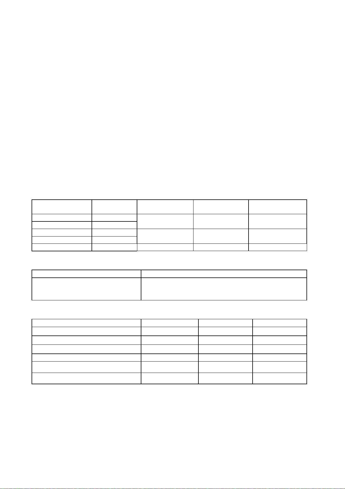
MODEL RADIATOR TYPE Distance to 100 W/cm
FR-1505 M3 (X, 6 kW) XN12AF (4’) none 2.1 m 75 W/cm2
XN20AF (6.5’)
FR-1510 M3 (X, 12 kW) XN12AF (4’) 1.1 m worst case 10.0 m worst case 200 W/cm2 worst case
XN20AF (6.5’)
FR-1525 M3 (X, 25 kW) XN20AF (6.5’) 1.1 m worst case 10.0 m worst case 200 W/cm2 worst case
Distance to 10 W/cm2
RF power density on
antenna aperture
Category of Equipment Units
Equipment for Protected Area Equipment for Exposed Area
Display unit
Power supply unit
Antenna unit (Scanner unit, RF Transceiver unit)
Performance monitor
Interswitch unit
Compass safe distance
Equipment unit Standard compass Steering compass Remarks
Display unit RDP-119 0.80 (0.50) m 0.50 (0.30) m
Antenna unit RTR-067 (6 kW) 1.40 (0.85) m 0.70 (0.45) m For all radiators
Antenna unit RTR-062 (12 kW) 1.70 (1.05) m 0.90 (0.55) m For all radiators
Antenna unit RTR-063 (25 kW) 2.10 (1.30) m 1.20 (0.75) m For all radiators
RF Transceiver unit
Performance monitor PM-30 (X-band) 0.4 m 0.3 m
Measurements by the BSH, Germany, Cert Nr. 287/2. Figures in ( ) apply to the coastal boats
under German Regulations.
x
Page 13
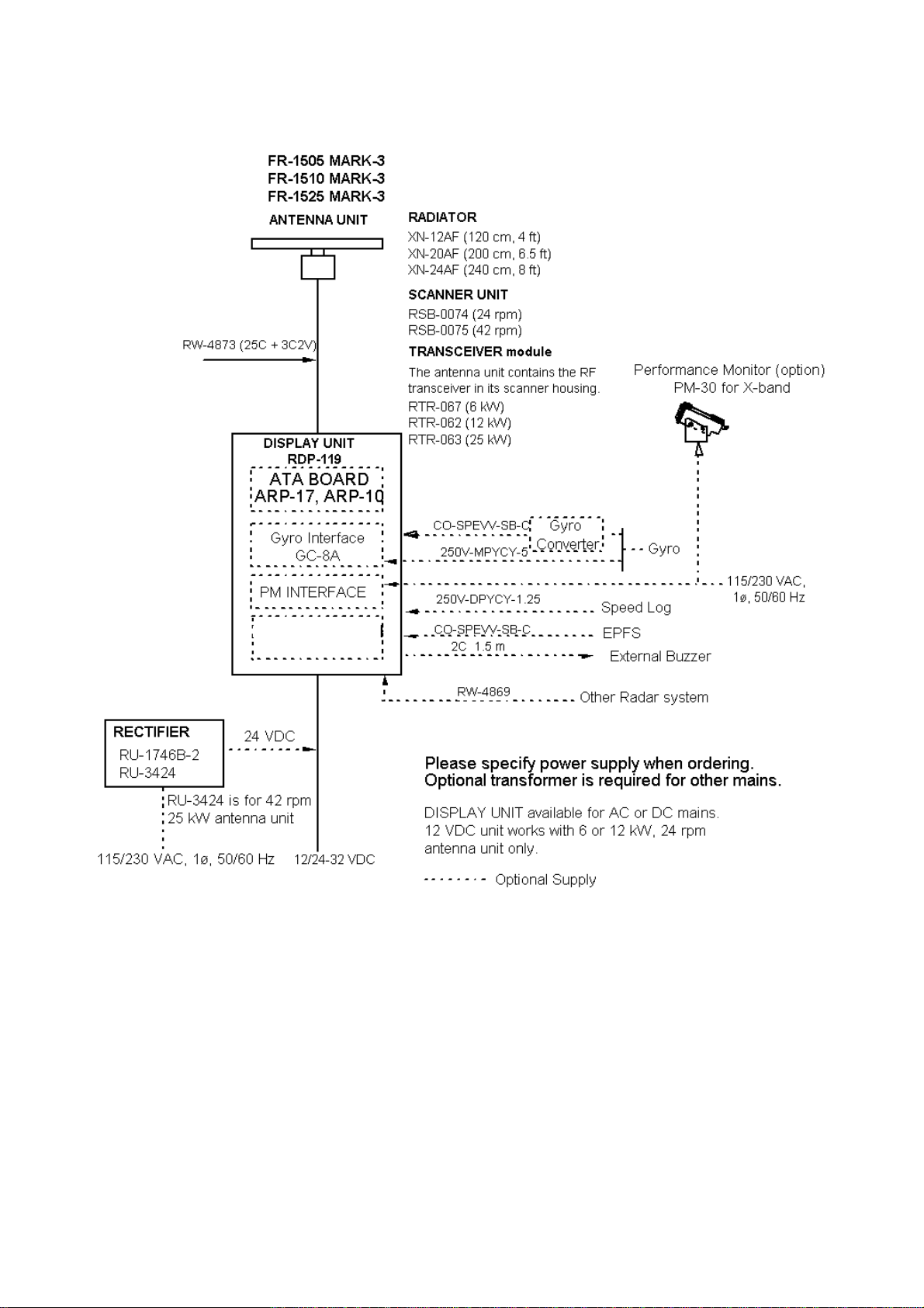
CONFIGURATION OF FR-1500 MARK-3 SERIES RADARS
VIDEO PLOTTER
RP-17 or RP-180
xi
Page 14

This page is intentionally left blank.
xii
Page 15
1 OPERATIONAL OVERVIEW
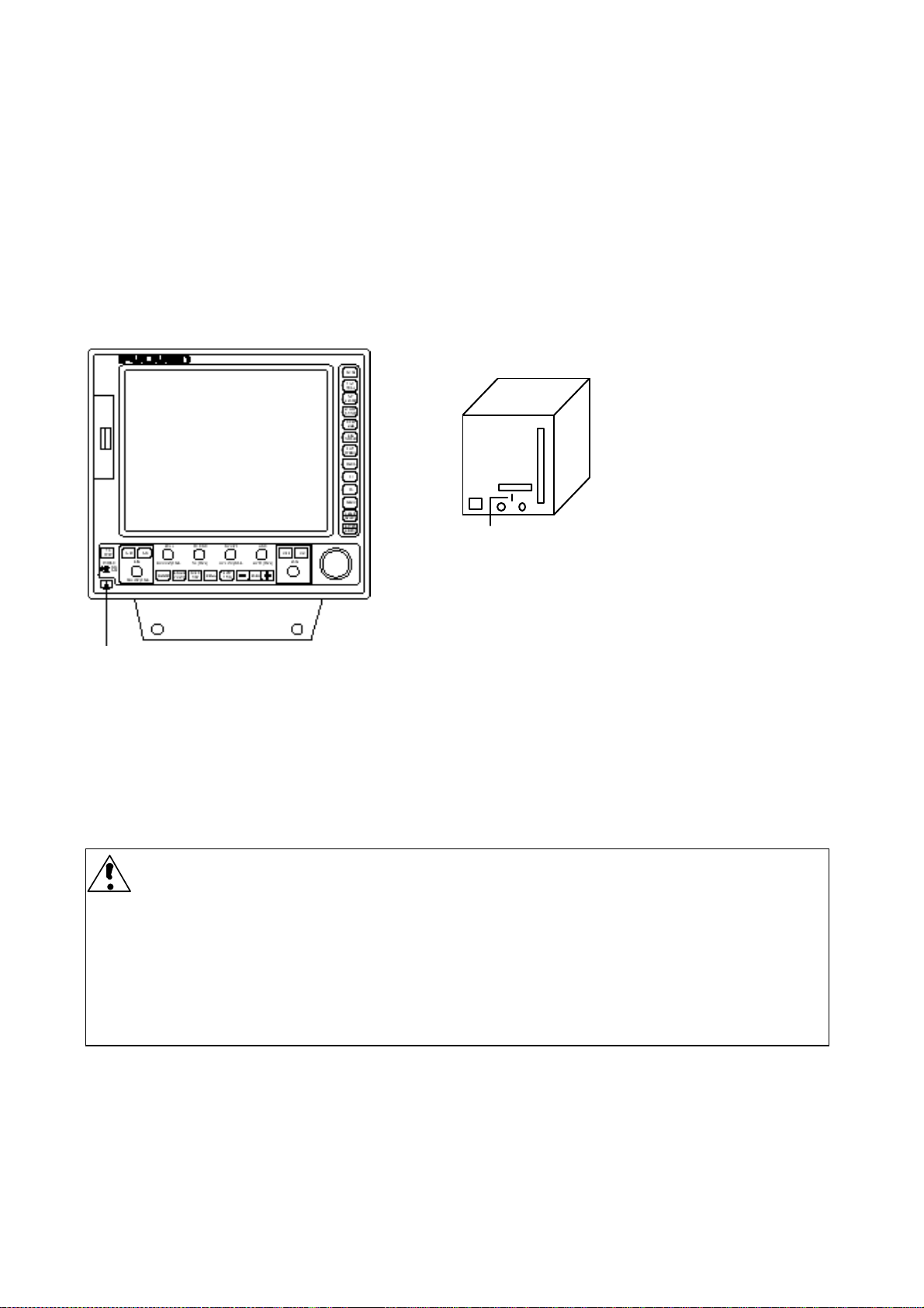
1.1 Turning on the Power
The [POWER] switch is located at the left corner of the display unit. Push it to switch on the radar
set. To turn off the radar, push it again. The screen shows the bearing scale and digital timer
approximately 15 seconds after power-on. The timer counts down three minutes of warm-up time.
During this period the magnetron, that is, the transmitter tube, is warmed for transmission. When
the timer has reached 0:00, the indication STBY appears, indicating that the radar is now ready to
transmit pulses.
POWER
switch
Switch S2
Notice for technicians
The display unit designed to run on AC voltage
has a switch (S2) at its rear to cut off 115/230 V
supply from internal circuits. Thus, the radar will
not operate when this switch is turned off. Keep it
in the ON position.
1.2 Transmitter ON
After the power is turned on and the magnetron has warmed up, STBY appears at the screen
center, indicating the radar is ready to transmit radar pulses. Press the [STBY/TX] key to transmit.
When you won’t be using the radar for an extended period, but you want to keep it in a state of
readiness, place it in standby by pressing the [STBY/TX] key. The display shows STBY.
Video Freeze-up Recovery
Video freeze-up or lock-up can occur unexpectedly on any digital rasterscan radars. This is
mainly caused by heavy spike noise in the power line and can be noticed by carefully watching
the nearly visible sweep line. If you suspect that the picture is not updated every scan of the
antenna or no key entry is accepted notwithstanding the apparently normal pictures, do Quick
Start to restore normal operation.
.1 Turn off the Power Switch and within 10 seconds turn it on again.
.2 Press the Transmit switch labeled STBY/TX for transmit condition.
-1.1-
Page 16
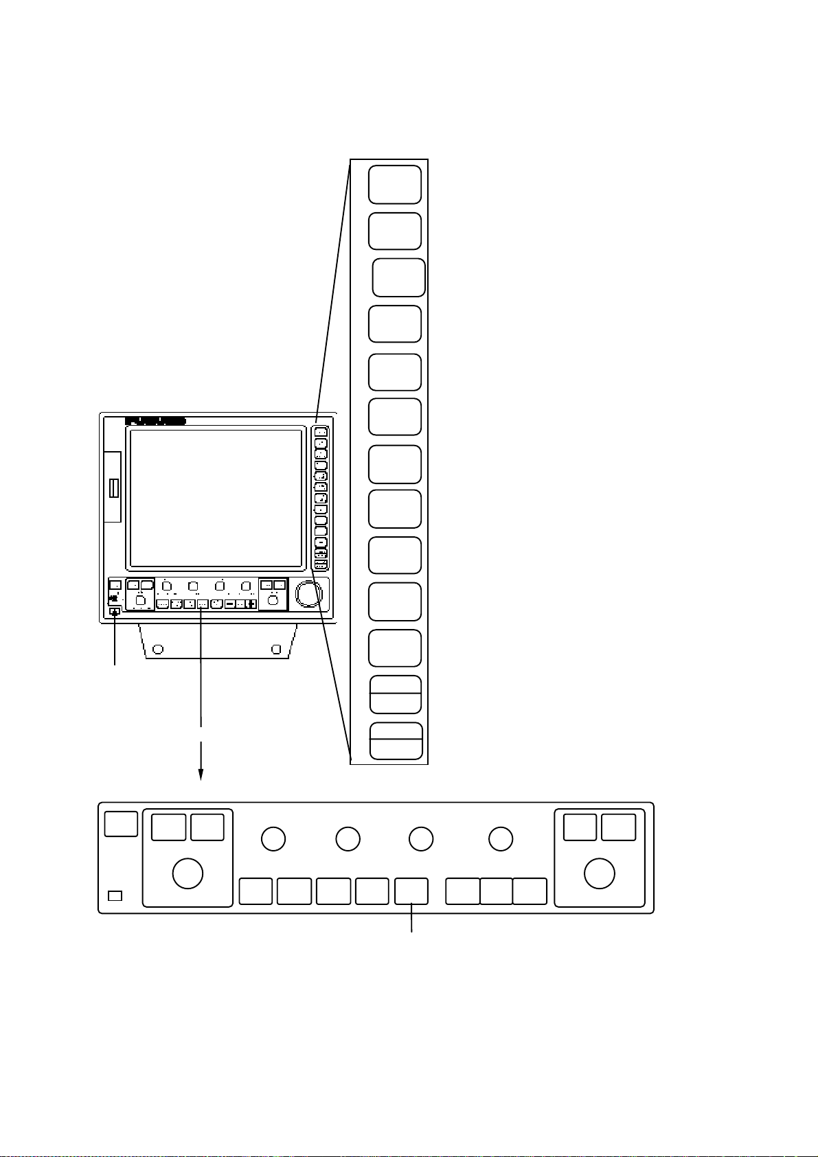
1.3 Control Description
USS (PUSH)
)
DAY/NIGHT (PUSH)
yp
(RM)
p
(RM)
(
r
g
g
MENU ACCESS CONTROL
PANEL
Function keys are also used as
numeral ke
ads for 0-9.
POWER
switch
DIRECT ACCESS CONTROL
TX
STBY
OFF
DEGA
EBL
ON
BRILL A/C RAIN A/C SEA
BKGND
DIMMER
COLOR
TLL: Target Latitude/Longitude outputted in IEC 61162-1 format.
TLL(PUSH
OFF
MODE
1
TGT
2
TRAIL
3
ALARM
SHIFT
4
ZOOM
INDEX
5
LINE
EBL
6
OFFSET
PLOT
7
SYMBOL
8
MARK
9
0
MENU
CANCEL
CLEAR
ENTER
SELECT
RINGS
resentation mode - Head-up
TGT
Press to select
, Head-up True Bearing (RM), Course-up
,North-up (RM), North-up (TM). Ref.
Target trails over selected time. Ref. 1.26.
Sets two target alarm zones. Ref. 1.22.
Off-centers the radar picture, turns on/off
R-type) or manual-resets the TM
Zoom
display. Ref. 1.23.
Controls Parallel Index Lines. Ref. 1.27.
Offset 1st EBL together with Cursor. Ref. 1.20.
Enters EPA mark. Ref. 1.25.
Inscribes reference marks (Ref. 1.28) o
marks in Radar map (Ref. 1.47).
F1
Selects functions of primary controls. Ref. 1.32.
F2
Selects setting of one of parameters visible on
STBY. Ref. 1.33.
Primary menu containing: Video Plot, Target
Trail, Tar
Function, Plot, Mark, Brill, Others. Ref. 1.6, etc.
Cancels entry, stops tracking.
et Alarm, Watch Time, Echo
Concludes entry of data, displays target data.
GAIN
RANGE
+
ION
Select FUNC 1, 2 or 3 which is a
settin
Ref. 1.34.
-
of picture effecting parameters.
OFF
VRM
ON
-1.2-
Page 17

1.4 CRT Brilliance
Operate the BRILL control on the control panel of the display unit to adjust the entire screen
brightness. Note that the optimum point of adjustment varies with ambient lighting conditions,
especially between daytime and nighttime.
1.5 Control Panel Backlighting
Operate the [DIMMER] key to adjust control panel backlighting.
1.6 Tuning the Receiver
1.6.1 Automatic tuning
The radar is set for automatic tuning at the factory. The radar receiver is tuned automatically each
time the power is turned on. The tuning indicator and the label AUTO at the top right corner of the
display unit show the tuning circuit is working. The receiver may become detuned, in automatic
tuning, if own ship’s radar receives the radar signal of another shipborne radar. To return, press
the [STBY/TX] key twice.
1.6.2 Manual tuning
Press the GAIN control (Push for HL OFF) and adjust the VRM control after setting as below:
1. Press the [MENU] key.
MENU
1. VIDEO PLOT*/ AIS
2. TGT TRAIL
3. TGT ALARM
4. WATCH TIME
5. ECHO SIG
6. FUNC
7. PLOT
8. MARK
9. BRILL
0. OTHERS
OTHERS
1. HDG SET
2. SPD MODE MAN LOG
LOG (S-BT)
LOG (S-WT)
3. MAN SPD
4. SET & DRIFT
5. DISPLAY
6. MARK/LINE
7. TUNE
8. NAV DATA
9. EBL/+/PI
0. ↓
TUNE
1. ↑
2. MODE AUTO MAN
* Requires RP-17 or RP-180. AIS not shown on RP-17.
(a) Main menu (b) OTHERS menu (c) TUNE menu
2. Press the [0] key twice to display the OTHERS menu. (b)
3. Press the [7] key to display the TUNE menu. (c)
4. Press the [2] key to select the option MAN from the MODE field.
5. Press the [ENTER/SELECT] key. While observing the picture on the 48-mile scale, slowly
adjust the VRM rotary control while holding down the GAIN control to find the best tuning
point. Make sure that the radar has been set to the best tuning point. This condition is
where the tuning indicator lights to about 80% of its total length. Note that the tuning
indication will never extend to full length.
6. Press the [MENU] key to close the menu.
-1.3-
Page 18

1.7 Degaussing the Screen
Each time the radar is turned on, the degaussing circuit automatically demagnetizes the CRT
screen to eliminate color contamination caused by earth’s magnetism or magnetized ship structure.
The screen is also degaussed automatically at certain time intervals, which may be selected on the
menu. While being degaussed, the screen may be disturbed momentarily with vertical lines. If you
wish to degauss by manual operation, push the EBL rotary control.
1.8 Initializing the Compass Readout
With a compass interfaced with the radar, ship’s heading is displayed at the top of the screen.
Upon turning on the radar, match the on-screen HDG readout with the compass reading by the
procedure shown below. Once you have set the initial heading correctly, resetting is not usually
required. However, if the HDG readout goes wrong for some reason, repeat the procedure to
correct it.
1. Press the [MENU] key to display the main menu.
2. Press the [0] key twice to display the OTHERS menu.
OTHERS
1. HDG SET
2. SPD MODE MAN LOG
LOG (S-BT)
LOG (S-WT)
3. MAN SPD
4. SET & DRIFT
5. DISPLAY
6. MARK/LINE
7. TUNE
8. NAV DATA
9. EBL/+/PI
↓
0.
NAV is additionally available in
R-type. If accuracy is doubtful,
do not use the speed data
obtained from GPS or DGPS.
3. Press the [1] key to select HDG SET.
4. Operate the VRM rotary control to duplicate the compass readout on the radar menu display.
5. Press the [ENTER/SELECT] key.
6. Press the [MENU] key to close the menu.
-1.4-
Page 19

1.9 Entering Own Ship’s Speed
EPA requires an own ship speed input and compass signal. The speed can be entered from a
speed log (automatic) or through the plotting keypad (manual).
1.9.1 Automatic speed input
1. Press the [MENU] key and the [0] key twice to show the OTHERS menu.
OTHERS
1. HDG SET
2. SPD MODE MAN LOG
LOG (S-BT)
LOG (S-WT)
3. MAN SPD
4. SET & DRIFT
5. DISPLAY
6. MARK/LINE
7. TUNE
8. NAV DATA
9. EBL/+/PI
0. ↓
NAV is additionally available
in R-type. If accuracy is
doubtful, do not use the speed
data obtained from GPS or
DGPS.
2. Press the [2] key to select the menu item SPD MODE.
3. Press the [2] key again to select the LOG option.
4. Press the [ENTER/SELECT] key to confirm your selection followed by the [MENU] key to close
the menu. The ship’s speed readout at the right-hand side of the screen shows own ship’s
speed fed from the speed log with the label LOG, BT or WT.
Notes:
1) IMO Resolution A.823(19) for ARPA recommends that a speed log to be interfaced with an
ARPA should be capable of providing through-the-water speed. The same concept applies to
the ATA and the EPA.
2) Be sure not to select LOG when a speed log is not connected. If the log signal is not provided,
the ship’s speed readout at the screen top will be blank.
1.9.2 Manual speed input
If the radar is not interfaced with a speed log, or the speed log does not feed correct speed enter
the ship’s speed as follows:
1. Press the [MENU] key and the [0] key twice to show the OTHERS menu.
2. Press the [2] key several times to select MAN from the SPD MODE field.
3. Press the [3] key to select the MAN SPD.
4. Enter speed with the numeric keys.
5. Press the [ENTER/SELECT] key to confirm your selection followed by the [MENU] key to close
the menu. The ship’s speed readout at the right-hand side of the screen shows own ship’s
speed fed from the speed log with the label MAN.
-1.5-
Page 20
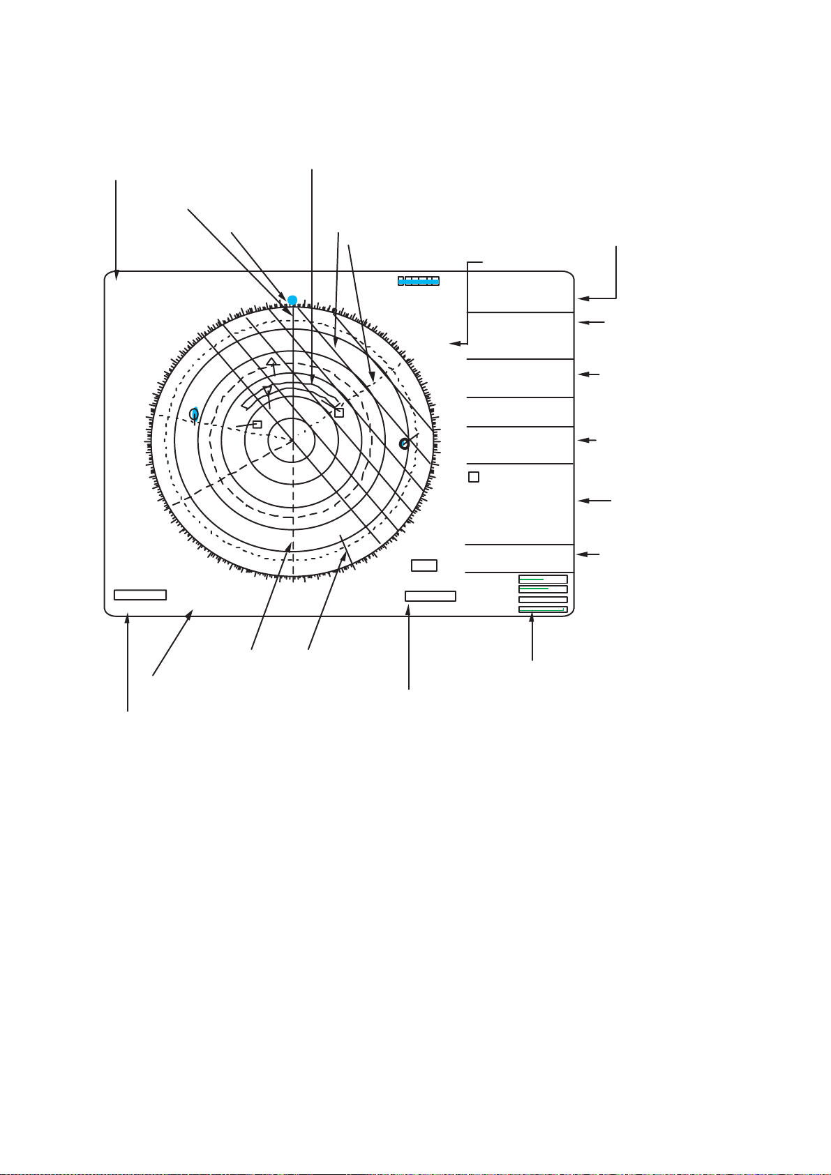
1.10 On-screen Legends and Markers
Range scale
Range ring interval
Pulselength
HU/HU TB/CU/NU/TM
Heading line
Heading marker
12
2NM
PULSE 1 M1
H U RM
FUNC1
COAST
IR1
ES1
NR
EAV0.5
A/C AUTO
CONTRAST1
2nd Echo
SART MAP ALIGN
320
310
300
290
280
270
260
250
240
230
220
EBL
287.2
°
R
°
R
240.0
340
330
+
210
200
PI
°
R
50
350
190
Target Alarm Zone (Radar) or Guard Zone (ATA),
1st zone between 3 and 6 nm, 2nd zone anywhere.
Own ship data
Parallel index lines
Parallel index line reference
Heading, Speed value
and sensor type
Geodetic datum
000
010
1
170
180
020
2
160
AUTO
030
150
WATCH TIM
00:00
040
140
SET DRIFT
REL TRAIL
12:34 30SEC
X-BAND
050
W84
060
120
130
TA1 TA2
IN IN
VRM
10.75NM
7.00 NM
MAIN
HDG 155.0° T GYRO
SPD 12.0KT WT
LOG 00.00KT F
00.00KT SB
+
OWN SHIP (GPS)
070
CSE 150.0T
WPT01
080
090
100
110
DEPTH 075.2m
TEMP 18.0°C
30-SEPT-1998
(LOCAL) 00:00
MAN 00:01
1 TRUE VECT
3Min WT
RNG 4.7NM
BRG 78.5°T
CSE 264.0°T WT
SPD 10.3K WT
CPA 2.9NM
TCPA 15:20
EPFS SIGNAL MISSING
TRIG. AZIMUTH
VIDEO GYRO LOG
GAIN
A/C SEA
A/C RAIN
BRILL
305.6° R
9.02NM
38 29 .562°N
138 18.562°E
TTG 45:50
38 32 .222°N
138 11.212°E
77.0°T
0.123NM
TTG 00:00
Cursor position
from OS, Time-To-Go
Own ship data
L/L, CMG
(Course Made Good
by GPS/DGPS)
Depth and Temperature
if sensors are used
ATA data
Warning of signal loss
Trigger/Azimuth/
Video/Gyro/Log
Stern marker
North marker
Control settings
Parallel index line reference 50°R
VRM. NO. 1 and NO. 2
EBL. NO. 1 and NO. 2
Active EBL is circumferenced
Active VRM is circumferenced
-1.6-
Page 21
1.11 Presentation Modes
This radar has the following presentation modes: Head-up, Head-up/TB, Course-up, North-up, and
True Motion.
1.11.1 Selecting presentation mode
Press the [MODE] key on the panel at the right side of the display unit. Each time the [MODE] key
is pressed, the presentation mode and mode indication at the upper-left corner of the screen
change cyclically.
Note: When a failure occurs in the gyrocompass, the radar will automatically be switched to
unstabilized presentation mode.
Loss of Gyrocompass signal
When the compass signal is lost, the presentation mode automatically becomes head-up and the
HDG (heading) readout at the top of the text area reads xxx.x°. Also GYRO SIGNAL MISSING
appears in red at the lower right corner on the screen. Press the MODE key, and the x’s go off.
Then, match the on-screen HDG readout with the heading value.
All compass related data will read Relative values.
-1.7-
Page 22
Presentation mode, representative display
Description
Heading Marker
North marker
320
310
300
290
280
270
260
250
240
230
220
000
010
350
340
330
+
210
200
170
190
180
Heading Line
020
030
040
140
150
160
050
060
070
080
090
100
110
120
130
Heading Marker
North marker
320
310
300
290
280
270
260
250
240
230
220
000
010
350
340
330
+
210
200
170
190
180
Heading Line
020
030
040
140
150
160
050
060
070
080
090
100
110
120
130
Bearing scale rotates with a compass signal
Heading Marker
330 340 350
320
310
300
290
280
270
260
250
240
230
220
210
200
190
180
170
000
010
North marker
020
030
040
050
060
+
130
140
150
160
070
080
090
100
110
120
Head-up mode
A display without azimuth stabilization in which the
line connecting the center with the top of the display
indicates own ship’s heading.
The target pips are painted at their measured
distances and in their directions relative to own ship’s
heading.
A shoreline on the bearing scale is the north marker
indicating compass north. A failure of the compass
input will cause the north marker to disappear and the
readout to show xxx.x° and the message GYRO
SIGNAL MISSING appears in red at the lower-right
corner of the screen.
Course-up mode
An azimuth stabilized display in which a line
connecting the center with the top of the display
indicates own ship’s intended course (namely, own
ship’s previous heading just before this mode has
been selected).
Target pips are painted at their measured distances
and in their directions relative to the intended course
which is maintained at the 0-degree position while the
heading line moves in accordance with ship’s yawing
and course change. This mode is useful to avoid
smearing of picture during course change. After a
course change, press the [SHIFT] key to reset the
picture orientation if you wish to continue using the
course-up mode. The heading line gets back to scale
zero.
Head-up TB (True Bearing) mode
Radar echoes are shown in the same way as in the
head-up mode. The difference from normal head-up
presentation lies in the orientation of the bearing
scale. The bearing scale is compass stabilized. That
is, it rotates in accordance with the compass signal,
enabling you to know own ship’s heading at a glance.
This mode is available only when the radar is
interfaced with a gyrocompass.
If the compass fails, the bearing scale returns to the
state of head-up mode.
-1.8-
Page 23
Presentation mode, representative display
North
350
340
330
320
310
300
290
280
270
260
250
240
230
220
210
200
190
North
350
340
330
320
310
300
290
280
270
260
250
240
230
220
210
200
190
000
010
+
170
180
000
010
+
170
180
Heading Line
020
030
040
050
060
070
110
120
130
140
150
160
Heading Line
020
160
Heading
030
040
Marker
050
060
070
110
120
130
140
150
Heading
Marker
080
090
100
080
090
100
Description
North-up modeIn the north-up mode, target pips
are painted at their measured distances and in their
true (compass) directions from own ship, north
bearing maintained up of the screen. The heading line
changes its direction according to the ship’s
heading.If the gyrocompass fails, the presentation
mode changes to head-up and the north marker
disappears. Also, the HDG readout shows xxx.x°. And
the message GYRO SIG MISSING appears in red at
the lower-right corner of the screen.
True motion mode
Own ship and other moving objects move in
accordance with their true courses and speed. In
ground stabilized TM, all fixed targets, such as
landmasses, appear as stationary echoes. In the sea
stabilized TM without set and drift inputs, the
landmass can move on the screen.
When own ship reaches a point corresponding to
75% of the radius of the display, it is automatically
reset to a point of 75% radius opposite to the
extension of the heading marker passing through the
display center. Resetting can be made at any moment
before the ship reaches the limit by pressing the
[SHIFT]. Automatic resetting is preceded by a beep
sound.
If the compass fails, the mode is changed to the
head-up and the north marker disappears. The HDG
readout shows xxx.x° and the message GYRO SIG
MISSING appears in red at the lower-right corner of
the screen.
000
010
350
340
330
320
310
300
290
280
270
260
250
240
230
220
210
200
020
030
040
050
060
070
080
+
160
170
190
180
090
100
110
120
130
140
150
320
310
300
290
280
270
260
250
240
230
220
000
010
350
340
330
210
200
020
030
Target trail
040
050
060
070
080
280
090
+
140
150
160
170
190
180
270
100
260
110
120
130
(a) True motion Is selected (b) Own ship has reached a
point 75% of display radius
000
010
350
340
330
320
310
300
290
250
240
230
220
210
200
020
030
040
050
060
070
080
+
160
170
190
180
090
100
110
120
130
140
150
(c) Own ship is automatically reset
to 75% of radius
-1.9-
Page 24
1.12 Selecting the Range Scale
The display range scale is changed by pressing the [+] and [-] keys. The selected range scale and
range ring interval are shown at the upper left corner on the screen. When a target of interest
comes closer, reduce the range scale so that it appears in 50-90% of the display radius. The range
scales are 0.125-0.25-0.5-0.75-1.5-3-6-12-24-48-96 nm.
Press the [RANGE] key to select range. The range, range ring interval and pulselength appear at
the top left corner of the display.
1.13 Selecting the Pulselength
The pulselength in use is displayed at the upper-left position. Appropriate pulselengths are preset
to individual range scales and function keys. Therefore, you are not usually required to select them.
If you are not satisfied with the current pulselength settings, however, it is possible to change them
by the ECHO SIG menu as below. The pulselength is selectable on the ranges 0.5 to 24 nm.
1.13.1 Selecting pulselength 1 or 2
1. Press the [MENU] key to display the Main menu.
2. Press the [5] key twice to select ECHO SIG.
3. Press the [6] key or [7] key to select PULSE 1 or PULSE 2 as appropriate.
4. Press the [ENTER/SELECT] key.
5. Press the [MENU] key.
The indication of PULSE 1 or PULSE 2 alternately appears at the upper left corner of the display.
PULSE 1
1. ↑
2. 0. 5NM S1 S2
3. 0.75-1.5NM S1 S2 M1
4. 3NM S1 S2 M1 M2 M3
5. 6-12NM M1 M2 M3 L 6.
24NM M2 M3 L
Underlined is the default value on each range.
0.07
0.15 µs
0.07 0.15
0.07 0.15
0.3 0.5
0.5 µs 0.7
0.7 1.2 µs
0.3 µs
0.3 0.5 0.7 µs
1.2 µs
1.13.2 Presetting pulselengths 1 and 2
Pulselength 1 and 2 can be preset on the PULSE 1 and PULSE 2 in the ECHO SIG menu. A
longer pulse provides an increased detection range, but with reduced discrimination. If you need
discrimination in preference to detection, choose a shorter pulse. However short the radar satisfies
the detecting requirements of the IMO.
1. Press the [MENU] key.
2. Press the [5] key twice to display the ECHO SIG menu.
3. Press the [6] or [7] key as appropriate to select PULSE 1 or PULSE 2.
4. Press appropriate numeric key among 2-7 to select pulselength and range.
5. Press the [ENTER/SELECT] key.
6. Press the [MENU] key.
-1.10-
Page 25
1.14 Adjusting the Sensitivity
The GAIN control adjusts the sensitivity of the receiver. It works in precisely the same manner as
the volume control of a broadcast receiver, amplifying the signals received.
The proper setting is such that the background noise is just visible on the screen. If you set up for
too little sensitivity, weak echoes may be missed. On the other hand excessive sensitivity yields
too much background noise; strong targets may be missed because of the poor contrast between
desired echoes and the background noise on the display.
To adjust receiver sensitivity, transmit on long range, and adjust the GAIN control so background
noise is just visible on the screen.
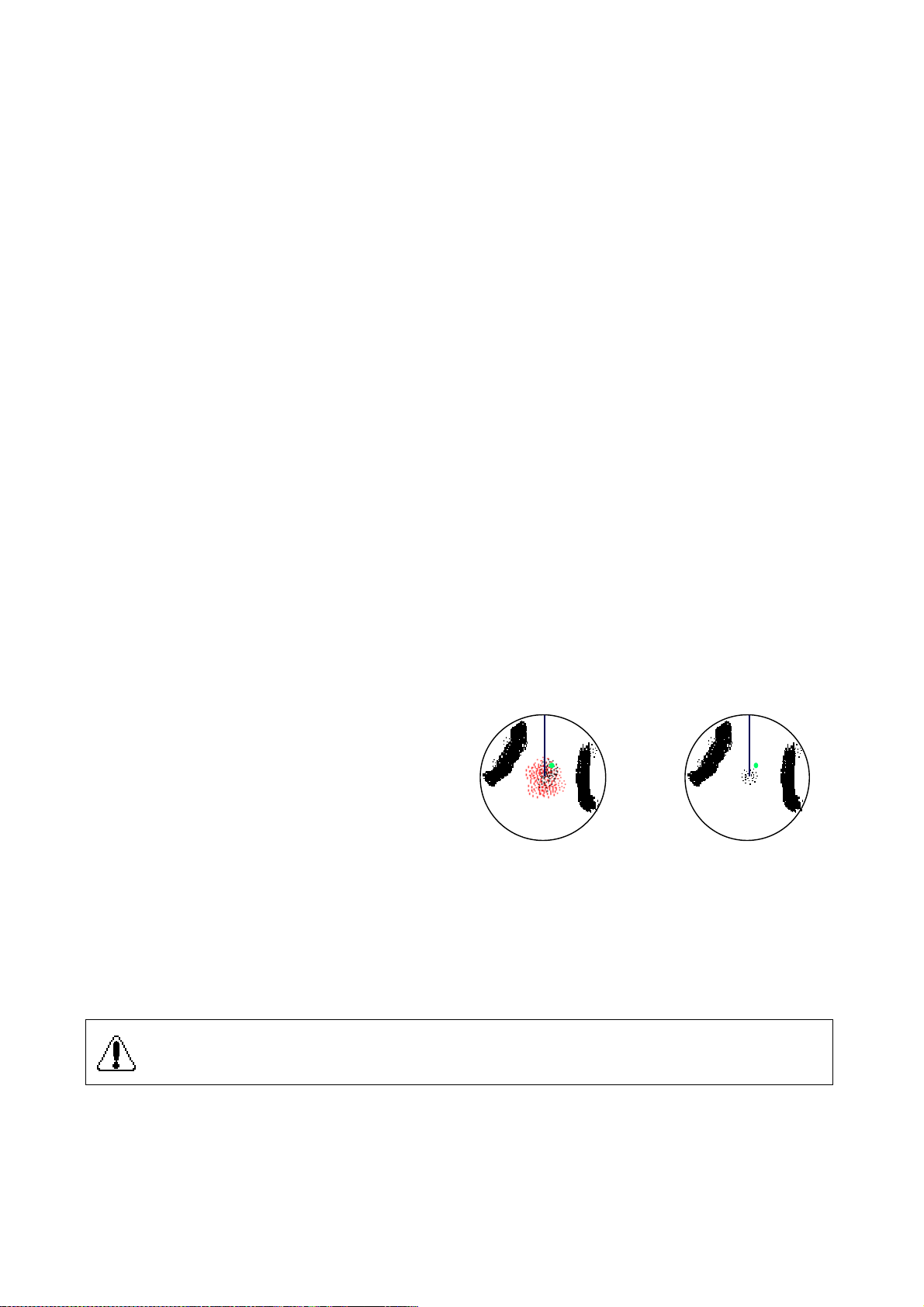
1.15 Suppressing Sea Clutter
Echoes from waves cover the central part of the display with random signals known as sea clutter.
The higher the waves, and the higher the scanner above the water, the further the clutter will
extend. When sea clutter masks the picture, suppress it by the A/C SEA control, rotate for manual
adjustment, push for automatic adjustment.
1.15.1 Manual adjustment by the A/C SEA control
The A/C SEA control reduces the amplification of echoes at short ranges (where clutter is the
greatest) and progressively increases amplification as the range increases, so amplification will be
normal at those ranges where there is no sea clutter.
The proper setting of the A/C SEA control should be such that the clutter is broken up into small
dots, and small targets become distinguishable.
If the control is set too low, targets will be hidden in the clutter, while if it is set too high, both sea
clutter and targets will disappear from the display. In most cases adjust the control until clutter has
disappeared to leeward, but a little is still visible windward.
1. Confirm that the sensitivity is properly
adjusted, and then transmit on short range.
2. Adjust the A/C SEA control so small targets
are distinguishable but some clutter remains
on the display.
A/C SEA OFF A/C SEA adjusted
1.15.2 Automatic adjustment by the A/C AUTO control
The A/C AUTO control automatically suppresses sea clutter as well as rain clutter. Push the A/C
SEA control to turn on the automatic A/C circuit. A/C AUTO appears at the bottom left corner when
the A/C circuit is on.
CAUTION
The auto A/C function can erase weak target echoes. Adjust the control carefully
watching the display.
-1.11-
Page 26
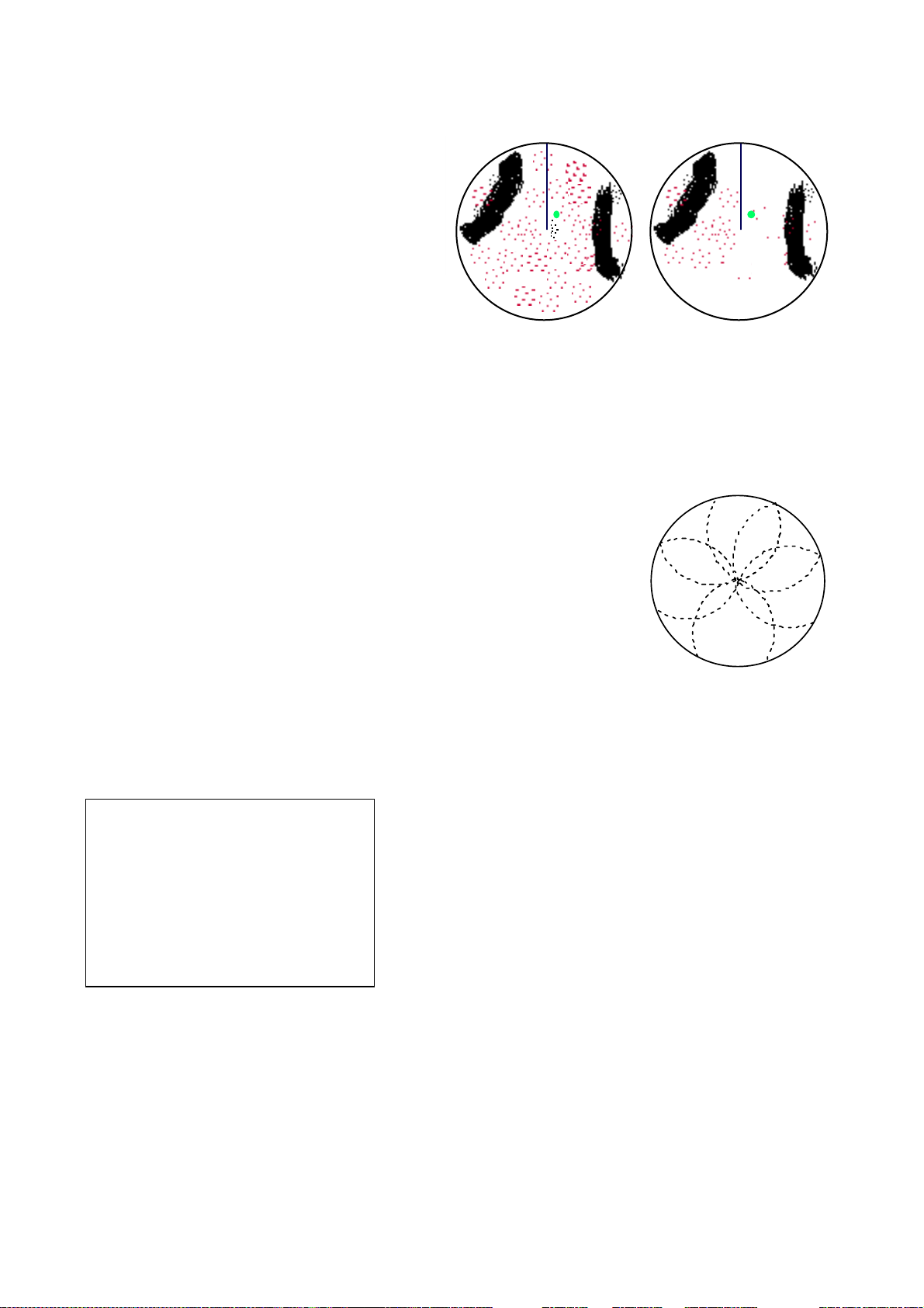
1.16 Suppressing Precipitation Clutter
The vertical beamwidth of the scanner is
designed to see surface targets even when the
ship is rolling. However, by this design the unit
will also detect rain clutter (rain, snow, or hail)
in the same manner as normal targets. Figure
at right shows the appearance of rain clutter
on the display.
The A/C RAIN control adjusts the receiver
sensitivity as the A/C SEA control does but
rather in a longer time period (longer range).
A/C RAIN OFF A/C RAIN ON – Thin clouds
Clockwise rotation of this control increases the
anti-clutter effect.
can be cleared
1.17 Interference Rejector
Mutual radar interference may occur in the vicinity of another shipborne
radar operating in the same frequency band (9 GHz). It is seen on the
screen as a number of bright spikes either in irregular patterns or in the
form of usually curved spoke-like dotted lines extending from the center
to the edge of the picture. Activating the interference rejector circuit can
reduce this type of interference.
The interference rejector is a kind of signal correlation circuit. It
compares the received signals over successive transmissions and
suppresses randomly occurring signals. There are three levels of
interference rejection depending on the number of transmissions that
are correlated. These are indicated by the legends IR1, IR2 and IR3 at
the upper-left position of the screen.
To activate the interference rejector;
1. Press the [F1] key. The following display appears.
1. VECTOR T/R
2. PULSE
3. INT REJ
4. STRETCH
5. ECHO AVG
6. CONTRAST
7. N REJ
8. DISP SEL
9. PM
0. SART
2. Press the [3] key to select interference rejection level (OFF, 1, 2, or 3) from the INT REJ field.
Selected level is shown as IR1, IR2 or IR3 at the bottom left-hand corner on the display.
-1.12-
Page 27

1.18 Measuring the Range
Use the fixed range rings to obtain a rough estimate of the range to a target. They are the
concentric solid circles about own ship, or the sweep origin. The number of rings is automatically
determined by the selected range scale and their interval is displayed at the upper-left position of
the screen.
1.18.1 Measuring range by the variable range marker (VRM)
Use the Variable Range Markers (VRMs) for more accurate measurement of the range to a target.
There are two VRMs, No.1 and No.2, which appear as dashed rings so that you can discriminate
them from the fixed range rings. The two VRMs can be distinguished from each other by different
lengths of dashes.
1. Press the [VRM ON] key to display either of the VRMs. Successive presses of the [VRM ON]
key toggles the active VRM between No.1 and No.2 and the currently active VRM readout is
circumscribed.
2. Rotate the VRM rotary control clockwise or counterclockwise to align the active VRM with the
inner edge of the target of interest and read its distance (unit: nm) at the lower-right corner of
the screen. Each VRM remains at the same geographical distance when you operate the
[RANGE+] or [RANGE-] key. This means that the apparent radius of the VRM ring changes in
proportion to the selected range scale.
3. Press the [VRM OFF] key to erase each VRM.
-1.13-
Page 28

1.19 Measuring Bearing
Use the Electronic Bearing Lines (EBLs) to find bearing of a target. There are two EBLs, No.1 and
No.2, which are toggled by successive presses of the [EBL ON] key. Each EBL is a straight
dashed line extending out from the own ship position up to the circumference of the radar picture.
The fine dashed line is the No.1 EBL and the coarse dashed one is the No.2 EBL.
1. Press the [EBL ON] key to display either of the EBLs. Successive presses of the [EBL ON]
key toggles the active EBL between No.1, No.2 and index lines (if displayed) and the
currently active EBL readout is circumscribed.
2. Rotate the EBL rotary control clockwise or counterclockwise until the active EBL bisects the
target of interest, and read its bearing at the lower-left corner of the screen.
3. Press the [EBL OFF] key to erase each EBL.
The EBL readout is affixed by R (relative) if it is relative to own ship’s heading, or T (true) if it is
referenced to the North, as determined by the item EBL/VRM/+ on the OTHERS menu.
Note 1: Bearing reference cannot be selected for IMO type (no menu selection). For the IMO
type, relative bearing is selected in the HU mode, and true bearing in HUTB, CU, NU and TM
modes.
Note 2: The cursor may be returned to OS position by pressing the VRM control (R-type only).
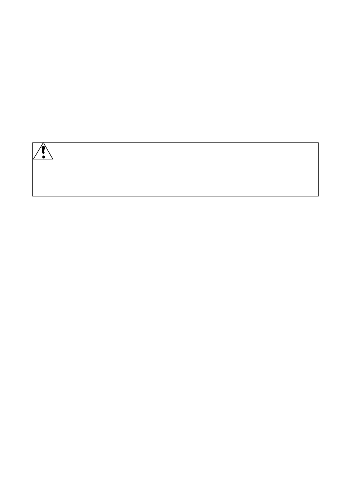
1.20 Collision Assessment by the Offset EBL
The origin of the EBL can be placed anywhere with the trackball to enable measurement of range
and bearing between any targets. This function is also useful for assessment of the potential risk of
collision.
To assess possibility of collision:
1. Press the [EBL ON] key to display or activate the No.1 EBL.
2. Place the cursor (+) on a target appearing as threatening (A in the illustrated example) by
operating the trackball.
3. Press the [EBL OFFSET] key, and the origin of the active EBL shifts to the cursor position.
Press the [EBL OFFSET] key again to anchor the EBL origin.
4. After waiting for a few minutes (at least 3 minutes), operate the EBL rotary control until the
EBL bisects the target at the new position (A'). The EBL readout shows the target ship’s
course, which may be true or relative depending on the settings on the OTHERS menu.
-1.14-
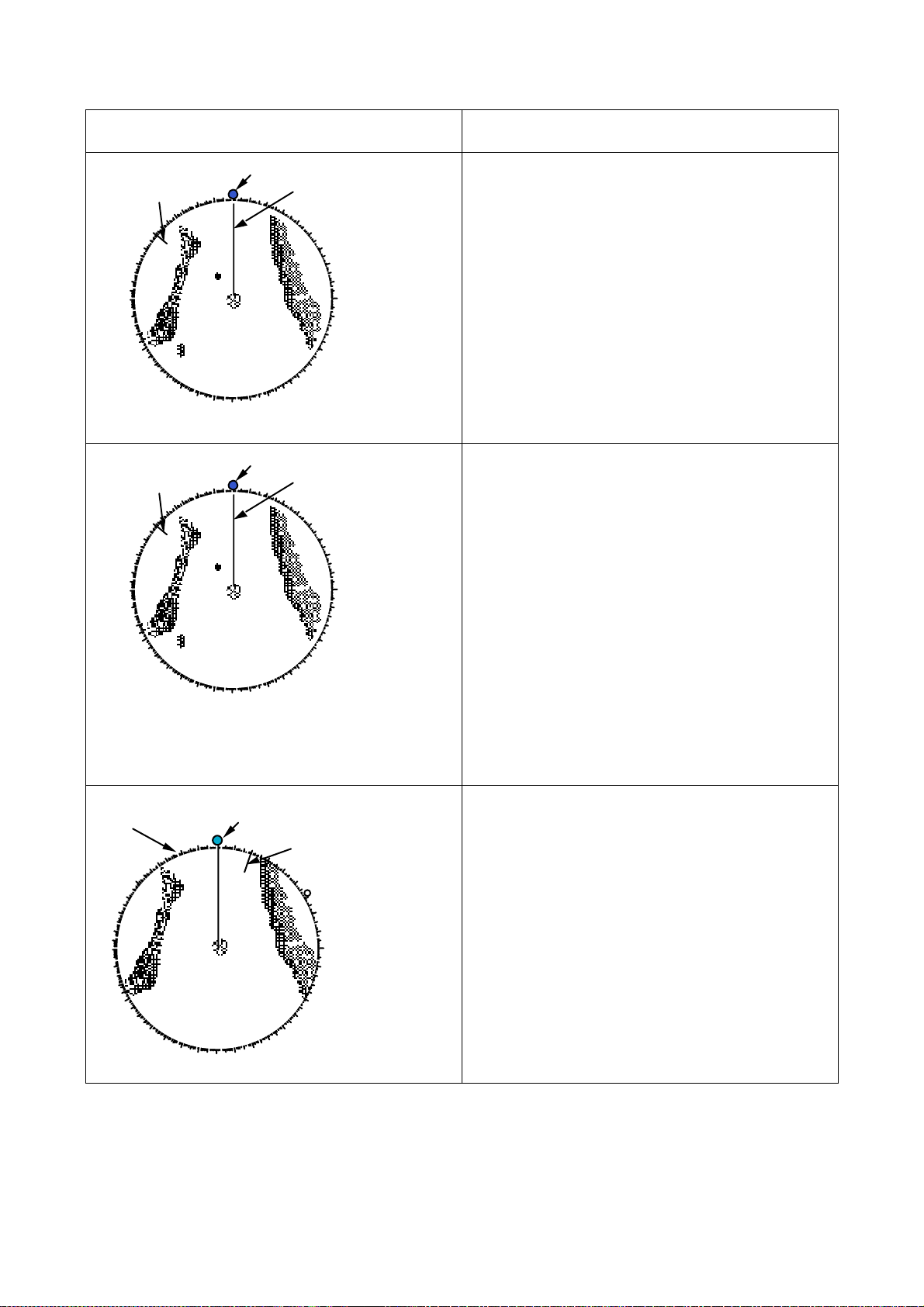
Page 29
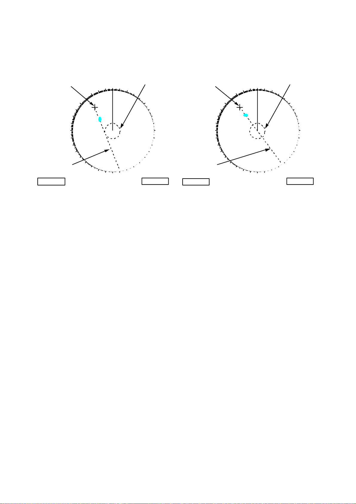
If relative motion is selected, it is also possible to read CPA (Closest Point of Approach) by
using a VRM as shown below (Figure (a)). If the EBL passes through the sweep origin
(own ship) as illustrated (Figure (b)), the target ship is on a collision course.
5. To return the EBL origin to the own ship position, press the [EBL OFFSET] key again.
CURSOR
EBL
150.3°R
290
280
270
260
250
EBL 1
300
240
230
310
320
220
330
210
340
350
020
A
A'
200
180
160
170190
030
150
040
050
130
140
3.85 NM
VRM 1
060
070
080
090
100
110
120
VRM
CURSOR
EBL
100.3°R
290
280
270
260
250
EBL 1
300
240
230
310
320
220
330
A
210
010
340
200
000
010
350
020
A'
160
170190
180
030
150
VRM 1
040
050
060
070
080
100
110
120
130
140
VRM
3.85 NM
000
(a) Evaluating the target ship course in RM (b) Target ship on collision course
090
-1.15-
Page 30
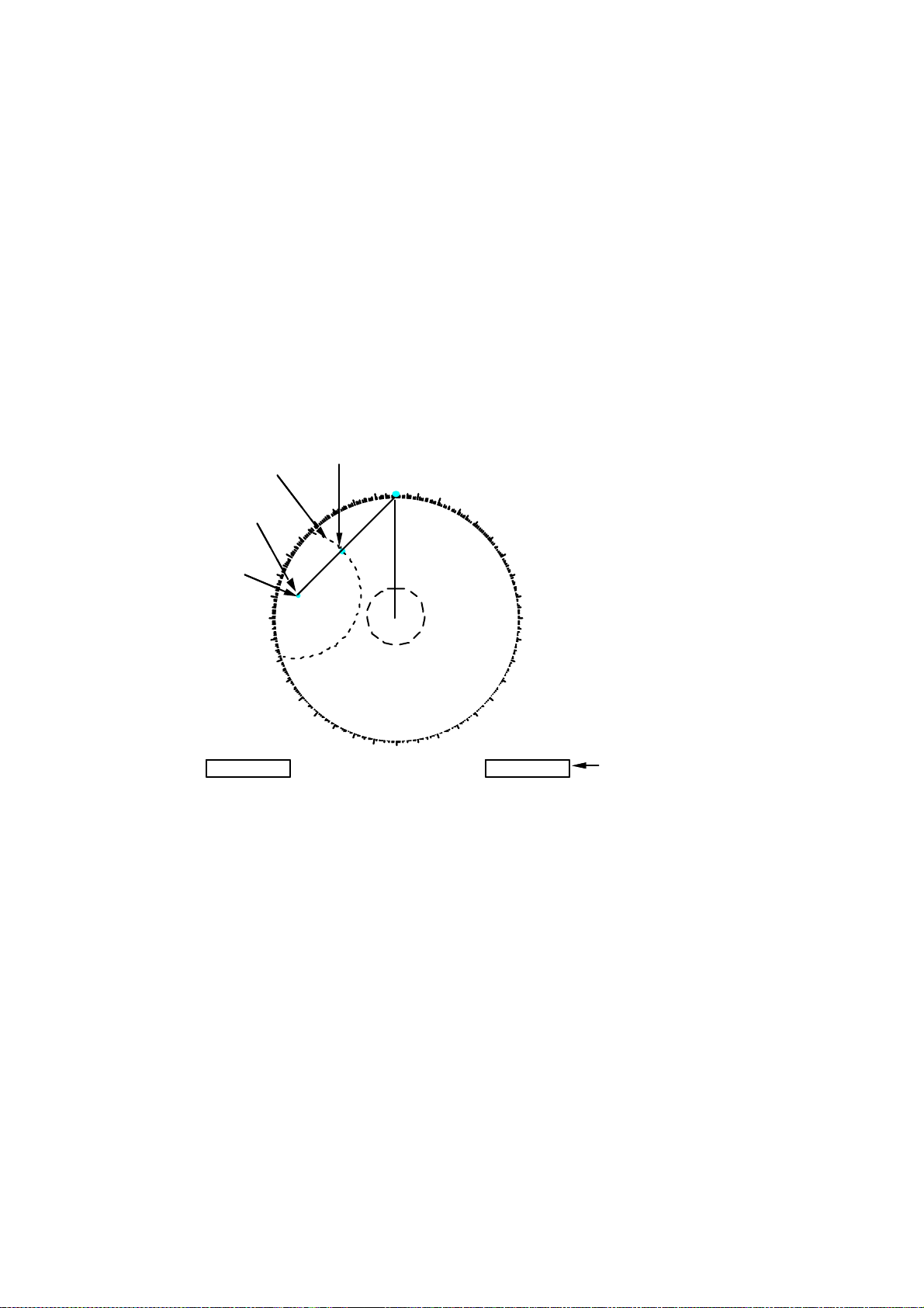
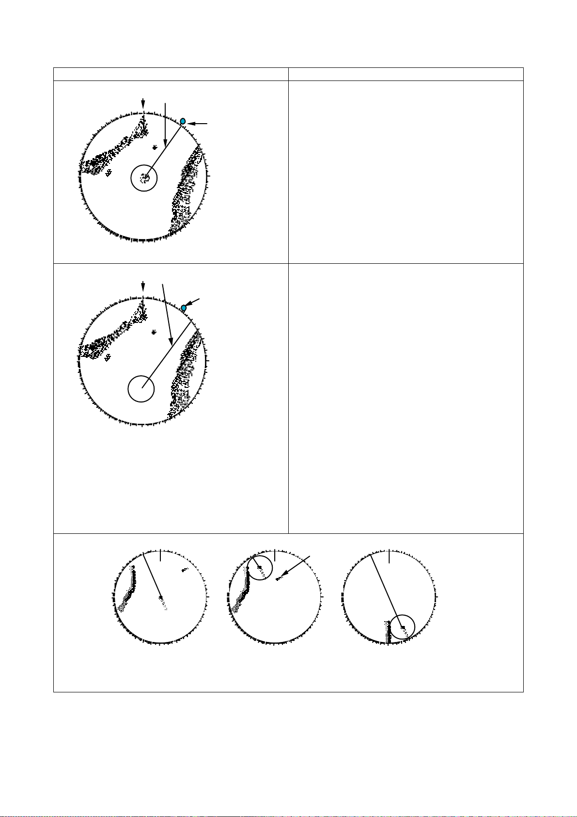
1.21 Measuring Range and Bearing Between Two Targets
1. Press the [EBL OFFSET] key, and place the origin of the No.1 EBL on a target of interest
(target 1 in the illustrated example) by operating the trackball. Note: Only No. 1 EBL can be
offset.
2. Turn the EBL rotary control until the EBL passes through another target of interest (target
2).
3. Turn the VRM rotary control until the range marker on the No. 1 EBL aligns with target 2.
The NO. 1 VRM readout at the lower-right corner of the screen indicates the distance
between the two targets.
4. To return the EBL origin to the own ship position, press the [EBL OFFSET] key again.
Bearing is shown relative to own ship with suffix “R” or as a true bearing with suffix “T” depending
on EBL relative/true settings on the OTHERS menu.
Target 2
220
220
320
320
Target 2
330
330
210
210
200
200
340
340
350
350
190
190
000
000
180
180
010
010
170
170
020
020
160
160
030
030
150
150
040
040
140
140
050
050
060
060
070
070
080
080
090
090
100
100
110
110
120
120
130
130
VRM
VRM
0.505NM
0.505NM
0.205NM
0.205NM
Distance between
Distance between
Targets 1 and 2
Targets 1 and 2
NO. 1 VRM
NO. 1 VRM
Target 1
Target 1
Origin of NO. 1 EBL
Origin of NO. 1 EBL
290
290
280
280
270
270
260
260
250
250
EBL
EBL
90.5°R
90.5°R
335.2°R
335.2°R
300
300
240
240
310
310
230
230
R: Bearing relative os heading viewed from Target 1 to 2
R: Bearing relative os heading viewed from Target 1 to 2
T: Bearing relative to north viewed from Target 1 to 2
T: Bearing relative to north viewed from Target 1 to 2
-1.16-
Page 31

1.22 Setting a Target Alarm Zone
CAUTION
The target alarm feature should never be relied upon as the sole means for detecting the risk of
potential collision. The operator of a ship is not relieved of the responsibility to keep lookout for
avoiding collisions, whether or not the radar is in use.
1.22.1 Introduction
There are two independent Target Alarm Zones. NO. 1 zone has a default coverage of 3.5-4 nm
and is adjustable within 3.0 to 6.0 nm. NO. 2 zone may be adjusted anywhere when the NO. 1 TAZ
is valid. On the R-type, the outer and inner boundaries can be set at any distance. In any radar
type, the sector of the zones can be set anywhere between 0 and 360 degrees in any direction.
When the radar is equipped with Automatic Tracking Aid (ATA) or ARPA, a Guard Zone alarm is
also available.
To set target alarm zones:
1. Press the [MENU] key and press the [3] key twice to show the TGT ALARM menu.
TGT ALARM
1. AREA NO. NO 1 NO 2
2. MODE 1 IN OUT
3. MODE 2 IN OUT
2. Press the [1] key to select guard zone to use NO 1 or NO 2.
3. Press the [ENTER/SELECT] key.
4. Press the [MENU] key.
5. Place the cursor (+) at point “A” (see figure below) using the trackball. Press the [TGT
ALARM ] key. SET TA1(2) appears at the lower-right corner on the screen. When both
alarms are prepared the active alarm is circumscribed.
6. Move the cursor (+) to point “B” and press the [TGT ALARM] key again. Then, an echo
watch zone as illustrated is created and the label TA1 (or 2) appears instead of SET TA1
(or 2) at the lower-right corner of the screen.
In R-type, you can use NO. 1 as TAZ by selecting IN
and NO. 2 as an Anchor Watch by selecting OUT. In
IMO type, only IN is available.
000
280
270
260
290
250
300
240
230
310
320
220
330
210
010
350
340
A
200
180
020
B
160
170190
030
150
040
140
TAZ
050
130
060
120
070
110
080
100
090
Target alarm zone (TAZ) can be set in any sector
between 3 and 6 nm on IMO-type, and anywhere on
the R-type.
When the radar has the ATA board ARP-17, a total of
3 alarm zones (two TAZs and one GZ) may be set.
The 2nd TAZ is available only when the 1st TAZ is
valid.
-1.17-
Page 32

Note: To create a target alarm zone having a 360-degree coverage around own ship, set
point B in almost the same direction (approx. ±3°) as point A and press the [TGT ALARM] key.
Two alarm zones can be set as described above. To change the active alarm zones, do steps 1
through 4 in the above procedure. (When both alarms are prepared the active alarm indication is
circumscribed.)
1.22.2 Acknowledging alarm
A target entering the ALARM zone produces both visual (flashing) and audible (beeping) alarms.
To silence the audible alarm, press the [AUDIO OFF] key shortly. ACK replaces IN (or OUT).
This will deactivate the audible alarm but will not stop the flashing of the target in the target alarm
zone. To reactivate the audible alarm, press the [AUDIO OFF] key again.
To silence the audible alarm, you may press the [AUDIO OFF] key. However, in this case, the label
ACKN does not appear.
Hold the [AUDIO OFF] key depressed for at least 5 seconds to disable the target alarm.
Note: The target alarm is given to targets having a certain level of echo strength. This level does
not always imply a landmass, reef, ships or other surface objects but can mean returns from the
sea surface or precipitation. Properly adjust the GAIN, A/C SEA, and A/C RAIN controls to reduce
noise to avoid generation of the guard alarm against false targets.
On the R-type, an inward or outward target alarm can be selected on the TGT ALARM menu. On
the IMO type, only the inward guard alarm is available. The inward guard alarm generates visual
and audible warnings when a target enters the target alarm zone from any direction. The outward
target alarm is produced when a target leaves the target alarm zone. (This is not a target alarm by
definition but an anchor watch, which some users find valuable.)
Inward alarm (IMO-type and R-type)
The radar causes an alarm when a
target violates the TAZ.
Outward alarm (R-type radar only)
The radar causes an alarm when a target
leaves the TAZ (Anchor watch).
1.23 Off-centering (shift)
Own ship position, or sweep origin, can be displaced to expand the view field without switching to a
larger range scale. The sweep origin can be off-centered to a point specified by the cursor, up to
75% of the range in use in any direction.
This feature is not available on the longest range scale or in the true motion mode. The number of
range rings increases keeping the original range intervals unchanged. To off center the radar
picture:
1. Place the cursor at a position where you wish to move the sweep origin by operating the
trackball.
2. Press the [SHIFT/ZOOM] key with a touch-and-release action. Then, the sweep origin is
off-centered to the cursor position. However, the heading line is left in the same position.
3. To cancel off-centering, press the [SHIFT/ZOOM] key again.
-1.18-
Page 33

+
CURSOR
+
CURSOR
(a) Select location with cursor (b) Press SHIFT key to offcenter
Note: The display is automatically reset to 75% of the range in use whenever the cursor is placed
at an edge of the effective display area. Note also that the heading marker (small circle on the
bearing scale) leaves the heading line on off-centered display, always indicating the correct
direction of the own ship heading.
1.24 Echo Averaging
The echo average feature effectively suppresses sea clutter. Echoes received from stable targets
such as ships appear on the screen at almost the same position every rotation of the scanner. On
the other hand, unstable echoes such as sea clutter appear at random positions.
To distinguish real target echoes from sea clutter, echo average performs scan-to-scan correlation.
Correlation is made by storing and averaging echo signals over successive picture frames. If an
echo is solid and stable, it is presented in its normal intensity. Sea clutter is averaged over
successive scans resulting in the reduced brilliance, making it easier to discriminate real targets
from sea clutter.
To properly use the echo average function, it is recommended to first suppress sea clutter with the
A/C SEA control and then do the following:
1. Press the [F1] key.
2. Press the [5] key twice to select ECHO AVG.
ECHO AVG
1. VECTOR T/R
2. PULSE
3. INT REJ
4. STRETCH
5. ECHO AVG
6. CONTRAST
7. N REJ
8. DISP SEL
9. PM
0. SART
3. Press the [5] key to select echo averaging level desired from the ECHO AVG field.
OFF: No averaging effect
0.5: Distinguishes small targets from sea clutter.
1: Helps distinguish targets from sea clutter and suppresses brilliance of unstable echoes.
2: Distinguishes small stationary targets such as navigation buoys.
3: Stably displays distant targets.
-1.19-
Page 34

(a) Echo average OFF (b) Echo average ON
Echo averaging uses scan-to-scan signal correlation technique based on the true motion over the
ground of each target. Thus, small stationary targets such as buoys will be shown while
suppressing random echoes such as sea clutter. True echo average is not however effective for
picking up small targets running at high speeds over the ground.
Echo average is inoperable when a compass signal is not available. If you wish to use this feature
without a compass signal, consult a FURUNO representative.
Do not use the Echo Average function under heavy pitching and rolling; loss of
target detection can result.
-1.20-
Page 35

1.25 Electronic Plotting Aid (EPA)
10 targets can be plotted electronically to assess their motion trend. Five past positions can be
displayed for each target. Working range of EPA is 0-48 nm irrespective of range scale. Note that
EPA is disabled when the ATA (ARP-17) is accommodated.
000 010
270
280
260
290
250
300
240
310
230
320
220
330
210
340
TAZ
200
350
190
180
170
020
030
040
1
050
2
140
130
120
060
070
080
090
100
110
MAN 00:01
3 TRUE VECT
3Min WT
RNG 4.7NM
BRG 41.5°T
CSE 198.0°T WT
SPD 10.3K WT
CPA 0.9NM
TCPA 15:20
3
1
150
160
Target data is shown in the data display area including range, bearing, course, speed, CPA and
TCPA of the last-plotted or selected target.
EPA SYMBOLS
○ Target plotted
□ Plotted target and the data being read
Flashing: Targets in Target Alarm Zone
Target 2 is on a collision course as the extension of its
vector goes through the own ship position. Placing the
offset EBL will help for assessment. TCPA is counted
up to 99.59 min and beyond that it is indicated as
TCPA > 99.99 min.
△ Target on a collision course
Note: Plots will be lost when the compass or speed log fails.
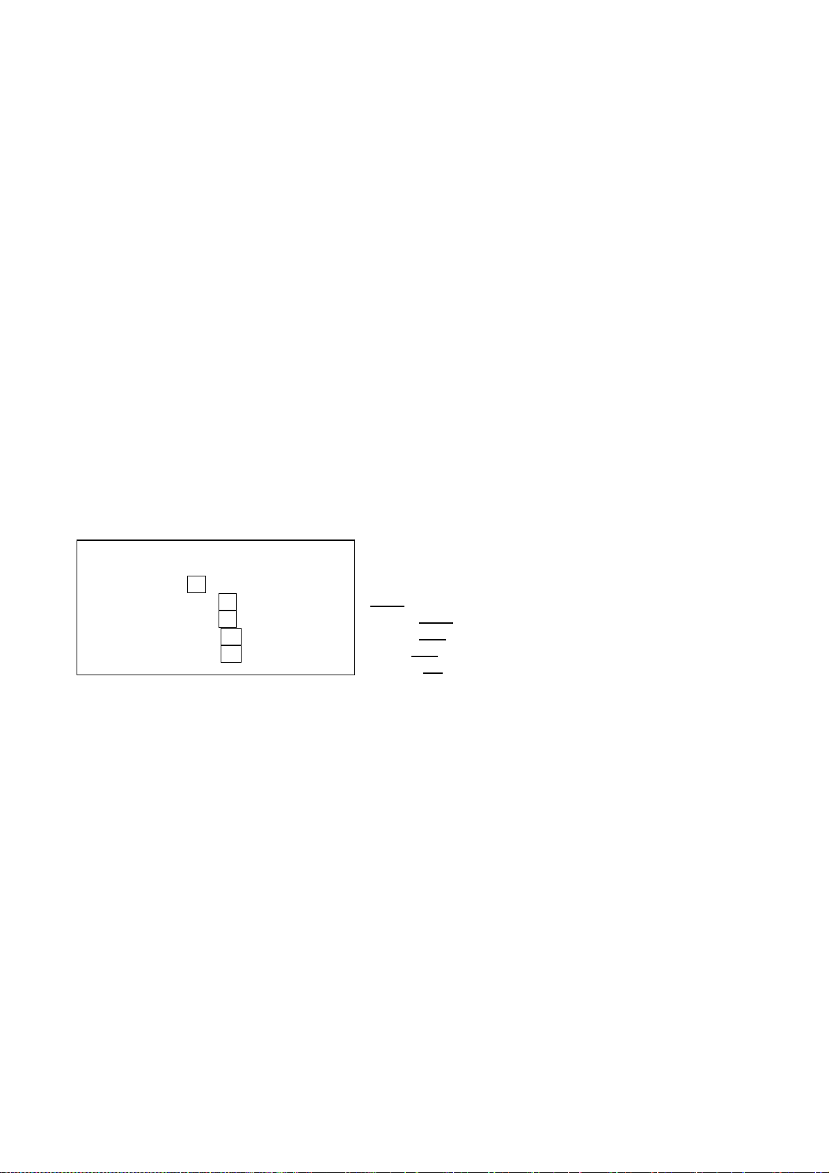
1.25.1 Plotting a target
1. Place a cursor on a target of interest and press the
[PLOT SYMBOL] key. The target position changes
with a calculated speed and course every 1-2 seconds
by the auto follow-up feature, maintaining the
calculation origin at point (a). If option (7) TRACK is
(c') Re-entry for correction
+
(a) First plot position
+
(b) Latest calculated
position
(c) 2nd plot position
ON, tracked positions are indicated by dots.
2. In more than 30 seconds but within 10 minutes, place the cursor on the latest calculated
position (b) and press the [ENTER/SELECT] key. The plot symbol changes from ○ to □. This
step is to identify the target on which you want the plotting data.
3. Place the cursor on the target within 5 seconds, maybe at a different location due to leeway at
(c), and press [PLOT SYMBOL] key. The vector will be drawn based on a trip between (a) and
(c). The target data is indicated in the text area to the right. Correction of plot position (c’), if
necessary, is possible within 5 seconds, to show the course made good and speed made good
(a-c’).
4. Do the same for other targets (maximum 10). For targets already in auto follow-up, do steps 2
and 3.
-1.21-
Page 36

Note: If a target once plotted is not plotted again within 10 minutes, the warning “UPDATE PLOT”
and plot number will appear on the lower right margin of the screen and the plot symbol of the
target flashes. Plotting of a target will be ceased if the time between consecutive plots exceeds 10
minutes. If you want to continue plotting this target, reacquire it within 5 minutes. Otherwise, the
target will be regarded as a “lost target” and its plot symbol and target data will be erased. The
larger the plotting interval, the less accurate the plotted target data. Plotting of each target should
normally be made every 3 or 6 minutes as far as possible. You can use the Watch Alarm to warn
yourself every 3 or 6 minutes.
1.25.2 Cancelling
Place the cursor on the plot symbol and press the [CANCEL/CLEAR] key.
1.25.3 Vectors
Vectors can be displayed relative to own ship’s heading (Relative) or with reference to the North
(True). This feature is available in all presentation modes (compass must be working correctly).
The current vector mode is indicated at the right of the screen.
Vector time (or the length of vectors) can be set to 30 seconds, 1, 3, 6, 15 or 30 minutes and the
selected vector time is indicated at the upper-right corner of the screen.
1. Press the [MENU] key followed by the [7] key twice to select PLOT.
2. Press the [3] key select REL or TRUE from the VECT REF field as
appropriate and press the [ENTER/SELECT] key.
3. Press the [4] to select appropriate vector time from the VECT TIME
field.
4. Press the [ENTER/SELECT] key to conclude your selection.
5. Press the [MENU] key to close the menu.
The vector tip shows an estimated position of the target after the selected
vector time elapses. It can be valuable to extend the vector length to
evaluate the risk of collision with any target.
The radar calculates motion trends (range, bearing, course, speed, CPA
and TCPA) of all plotted targets.
In the head-up and head-up true bearing modes, target bearing, course
and speed shown in the upper-right target data field become true (T)
relative to north or relative (R) relative to own ship in accordance with
true/relative vector setting. In the North-Up, Course-Up, and True Motion
modes, the target data field always displays true bearing, true course and
speed over the ground.
PLOT MENU 1
1. MARK DISP
OFF ON
2. ERASE
3. VECT REF
REL TRUE
4. VECT TIME
(min)
30sec 1 3 6
15 30
5. CPA SET
OFF 0.5NM 1NM
1.5NM 2NM 3NM
4NM 5NM 6NM
6. TCPA SET
(min)
30sec 1 2 3 4
5 6 12 15
7. TRACK
OFF ON
1.25.4 Reading the target data
8. AUDIO ALARM
OFF ON
9. PLOT No. DISP
OFF ON
Place cursor on the target and press the [ENTER/SELECT] key. The selected target is marked
with . The following target data is displayed at the right side of the CRT.
RNG/BRG (Range/Bearing): Range and bearing from own ship to last-plotted target with suffix T
(True).
CSE/SPD (Course/Speed): Course and speed are displayed for the last-plotted target with suffix T
(True).
CPA/TCPA: CPA (Closest Point of Approach) is the closest range the target will approach to own
ship. TCPA is the time to CPA. Both CPA and TCPA are automatically calculated. TCPA is
counted up to 99.59 min and beyond that it is indicated as TCPA > *99.59 MIN.
-1.22-
Page 37

1.25.5 Terminating target plotting
With EPA you can plot up to 10 targets. You may wish to terminate plotting of less important
targets to newly plot other threatening targets.
With Trackball: Place the cursor (+) on a target which you do not want to be tracked any longer by
operating the trackball and press the [CANCEL/CLEAR] key.
All Targets: To terminate plotting of all targets at once:
1. Press the [MENU] key followed by the [7] key.
2. Press the [2] key twice to select OFF from the ERASE field.
3. Press the [ENTER/SELECT] key followed by the [MENU] key.
1.25.6 Setting CPA/TCPA alarm ranges
When the predicted CPA of any target becomes smaller than a preset CPA alarm range and its
predicted TCPA less than a preset TCPA alarm limit, the EPA releases an audible alarm and
displays the warning indication COLLISION on the screen. In addition, the EPA symbol changes to
a triangle and flashes together with its vector.
Provided that this feature is used correctly, it will help prevent the risk of collision by alerting you to
threatening targets. It is important that GAIN, A/C SEA, A/C RAIN and other radar controls are
properly adjusted.
CPA/TCPA alarm ranges must be set up properly taking into consideration the size, tonnage,
speed, turning performance and other characteristics of own ship.
CAUTION
CPA/TCPA
The CPA/TCPA alarm feature should never be relied upon as the sole means for detecting the
risk of collision. The navigator is not relieved of the responsibility to keep visual lookout for
avoiding collisions, whether or not the radar or other plotting aid is in use.
To set the CPA/TCPA alarm ranges:
1. Press the [MENU] key.
2. Press the [7] key twice to display the PLOT 1 menu.
3. Press the [5] key for CPA SET or [6] key for TCPA set.
4. Press the [5] key or [6] key again to select CPA or TCPA range desired.
5. Press the [ENTER/SELECT] key to register your selection.
6. Press the [MENU] key to close the menu.
1.25.7 Silencing CPA/TCPA audible alarm
Press the [AUDIO OFF] key to acknowledge and silence the CPA/TCPA audible alarm.
The warning label COLLISION and the flashing of the triangle plot symbol and vector remain on
the screen until the dangerous situation is gone or you intentionally terminate tracking of the target
by using the trackball.
-1.23-
Page 38

1.25.8 Past plot points
Past plot points may be marked on the display by dots. Up to nine dots can be displayed as
follows:
1. Press the [MENU] key.
2. Press the [7] key twice to reach the PLOT MENU 1.
3. Press the [7] key to select OFF or ON from the TRACK field as appropriate.
4. Press the [ENTER/SELECT] key to register your selection followed by the [MENU] key to
close the menu.
1.25.9 Displaying plot No.
Plot numbers can be turned on/off as follows.
1. Press the [MENU] key followed by [7] key twice to show PLOT MENU 1.
2. Press the [9] key to select PLOT No. DISP ON or OFF as appropriate.
3. Press the [ENTER/SELECT] key to register your selection followed by the [MENU] key to
close the menu.
1.26 Target Trails (Echo Trails)
It is possible to display the trails of the radar echoes of targets in the form of synthetic afterglow.
Target trails are selected either relative or true and may be sea or ground stabilized. The simulated
afterglow can be selected in a single tone or gradual shading depending on a setting on the TGT
TRAIL menu.
1.26.1 True or relative trails
Target trails may be displayed relative to north or own ship’s heading on Relative Motion, and only
relative to north on True Motion. True motion trails require a compass signal and own ship speed
input.
(a) True target trails – no smearing of
stationary targets
(b) Relative target trails – all targets
moving relative to own ship
Note: When true trail is selected on the RM mode, the legend TRUE TRAIL appears in red.
To select true or relative target trail presentation:
1. Press the [MENU] key.
2. Press the [2] key twice to show the TGT TRAIL menu.
-1.24-
Page 39

TGT TRAIL
1. TIME (min) 15sec 30sec 1 3 6
15 30 CONT
2. MODE REL TRUE
3. SHADE MONO MULTI
4. LEVEL 1 2 3
5. TRAIL COPY OFF ON
6. THIN TRAIL OFF ON
7. THIN MODE 1 2 3 4
(7. R-type only)
3. Press the [2] key several times to select REL or TRUE from the MODE field as appropriate.
4. Press the [ENTER/SELECT] key to confirm your selection, then the [MENU] key to close
the menu.
1.26.2 Trail gradation
Target trails may be shown in monotone or multitone. Gradual shading paints the trails getting
thinner with time just like the afterglow on an analog PPI radar.
Monotone Multitone
1. Press the [MENU] key.
2. Press the [2] key twice to select TGT TRAIL.
3. Press the [3] key to select MONO or MULTI from the SHADE field as appropriate.
4. Press the [ENTER/SELECT] key and the [MENU] key in order.
1.26.3 Displaying and erasing target trails
Press the [TGT TRAIL] key to activate or deactivate the target trails feature. The current target trail
setting is displayed at the upper right-and corner of the screen.
Note: Holding the [TGT TRAIL] key depressed for about 3 seconds will cause a loss of target
trail data so far stored in memory.
1.26.4 Thin trails
Target trails may be painted in thinner trails. This is useful when there are a lot targets and
their trails would create congestion on the screen.
1. Press the [MENU] key.
2. Press the [2] key twice to select TGT TRAIL.
3. Press the [6] key to select ON or OFF from the THIN TRAIL field as appropriate.
4. For the R-type radar, you may select the degree of thinness from the THIN MODE field.
The higher the number the thinner the trail. Press the [7] key to select degree of thinness
desired.
5. Press the [ENTER/SELECT] key and the [MENU] key in order.
-1.25-
Page 40

1.26.5 Restoring trails
Trails are cancelled and restarted whenever the range is changed. However, you can continue
trails on the same range, without restarting, when the range is changed to a next larger or smaller
range scale. Note however that when the range is changed, only those target trails within the
previous range are continued; no trails are generated for targets outside of the previous range.
1. Press the [MENU] key.
No trail generated for targets
not within previous range
2. Press the [2] key twice to select
TGT TRAIL.
3. Press the [5] key to select ON from
the TRAIL COPY field.
4. Press the [ENTER/SELECT] key
and [MENU] key in order.
1.26.6 Resetting target trails
(a) Previous range (b) New range
To reset (or clear) the target trail memory, hold the [TGT TRAIL] key depressed for about 3
seconds. Target trails are cleared and the trailing process restarts from time count zero at current
target trail plot interval.
1.26.7 Trail brilliance
The brilliance of target trails can be adjusted on the BRILL menu as follows:
1. Press the [MENU] key.
2. Press the [9] key twice to display the BRILL menu.
BRILL
1. TGT TRAIL
2. CHARACTER
3. HDG LINE
4. EBL/VRM
5. CURSOR
6. MARK
7. PLOT
8. OS SYMB
9. ↓
Menu item No. 9 requires RP-17 board.
3. Press the [1] key to select TGT TRAIL.
4. Operate the VRM rotary control to adjust brilliance. Current brilliance is shown by the bar
graph.
5. Press the [ENTER/SELECT] key to conclude your selection followed by the [MENU] key to
close the menu.
-1.26-
Page 41

1.27 Parallel Index Lines
Parallel index lines are useful for keeping a constant distance between own ship and a coastline or
a partner ship when navigating. The orientation of the index lines is controlled with the EBL rotary
control and the intervals between the lines is adjustable with the VRM rotary control (provided that
No.2 VRM is active).
1.27.1 Displaying/erasing the index lines
Press the [INDEX LINE] key to disconnect the VRM. Press the
[INDEX LINE] key to display/erase the index lines.
1.27.2 Selecting number of index lines to display
Maximum number of the index lines can be set for 2 or 6 on the
MARK/LINE sub menu in the OTHERS menu.
Bearing of PI Lines
1.28 Reference Mark (not available with Video Plotter RP-17 or RP-180)
You can mark any reference points, prominent target or a point of particular interest using the
reference mark feature. This mark is geographically fixed, namely, ground stabilized. Twenty such
reference marks can be entered. Note this feature is inoperative when the RP-17 or RP-180 is
installed.
To use the reference mark:
1. Place the cursor (+) at a point where you want to place a reference mark by operating the
trackball.
2. Press the [MARK] key. The reference mark appears at the cursor position. The cursor
location is indicated on the screen.
1.28.1 Inscribing mark reference
The reference mark can be set relative to own ship, or referenced to land (sea or ground
stabilized).
1. Press the [MENU] key.
2. Press the [8] key twice to select MARK.
MARK
1. ERASE
2. MODE REL TRUE
3. Press the [2] to select the REL or TRUE as required.
4. Press the [ENTER/SELECT] key, then [MENU].
1.28.2 Erasing reference marks
Erasing i ndividual ref eren ce marks
Select the Reference mark with the cursor and then press the [CANCEL/CLEAR] key.
-1.27-
Page 42

1.28.3 Erasing all reference marks
1. Press the [MENU] key.
2. Press the [8] key twice to select MARK.
3. Press the [1] key twice.
4. Press the [MENU] key.
1.29 Zoom (R-type only)
The zoom function is available on the R-type radar only, and it enlarges an area of interest as large
as twice the normal viewing.
1. Place the cursor (+) close to the point of interest by operating the trackball.
2. Press and hold down the [SHIFT/ZOOM] key for about two seconds. The area around the
cursor and own ship is enlarged twice as large as the original size.
3. To cancel zoom, press and hold down the [SHIFT/ZOOM] key about two seconds.
Note: The zoom feature is inoperative when the display is off centered.
Place the cursor at a
position of interest
+
Cursor
ZOOM in
(Regular type only)
-1.28-
Page 43

1.30 Markers
Heading line, north marker, stern marker, own ship symbol
The heading line indicates the ship’s heading in all presentation modes. It is a line from the own
ship position to the outer edge of the radar display area and appears at zero degrees on the
bearing scale in head-up mode, it changes the orientation depending on the ship orientation in the
north-up and true motion modes. The heading marker appears as a small circle on the bearing
scale to indicate the heading when the display is shifted or is in the north-up or TM mode.
Temporarily erasing heading line, north marker, stern marker, own ship symbol
To temporarily extinguish the heading line to look at targets existing dead ahead of own ship, press
the GAIN control. The heading line reappears when the control is released.
Note that the Video Plotter screen (requires RP-17) is also temporarily erased when the GAIN
control is pressed.
North marker
The north marker appears as a short dashed line. In the head-up mode, the north marker moves
around the bearing scale in accordance with the compass signal.
Stern marker
The stern marker (a dot-and-dash line) appears opposite to the heading line. It can be
displayed/erased on the MARK/LINE sub menu in the OTHERS menu ([MENU], [0], [0]).
Own ship symbol
The own ship symbol ( ) can be displayed/erased on the MARK/LINE sub menu in the OTHERS
menu. The symbol is scaled to indicate the length and beam of the vessel. If the largest dimension
of the symbol gets smaller than 6 mm, the symbol will disappear and own ship will be represented
with a small dot or circle depending on the range in use. NOTE: Details should be entered during
installation.
-1.29-
Page 44

1.31 Suppressing Second-trace Echoes
In certain situations, echoes from very distant targets may appear as false echoes (second-trace
echoes) on the screen. This occurs when the return echo is received one transmission cycle later,
that is, after a next radar pulse has been transmitted.
To activate or deactivate the second-trace echo rejector:
1. Press the [MENU] key followed by the [5] key twice to display the ECHO SIG menu.
ECHO SIG
1. COLOR YEL GRN *
2. CLTR SWEEP OFF ON (LINK) ON(FIX)
3. SWEEP LEVEL 1 2 3
4. ENHANCE OFF ON
ND
5. 2
6. PULSE 1
7. PULSE 2
8. A/D CURVE A B C D
9. CNTR ENHANCE OFF ON
0. REALTIME HU OFF ON
ECHO OFF ON
2. Press the [5] key to select OFF or ON.
* COLOR additional to R-type
(8. R-type only)
(9. R-type only)
(0. R-type only)
3. Press the [ENTER/SELECT] key to conclude your selection followed by the [MENU] key to
close the menu.
1.32 [F1] Key
The [F1] key allows instant access to the primary function controls.
1. Press the [F1] key. The following menu appears.
1. VECTOR T/R
2. PULSE
3. INT REJ
4. STRETCH
5. ECHO AVG
6. CONTRAST
7. N REJ
8. DISP SEL
9. PM
0. SART
2. Press appropriate numeric key. For example, press the [4] key to select desired echo
stretch level. Each press of the [4] key selects echo stretch level.
Vector mode: True or Relative. Press [F1], [1].
Pulselength selection
Interference rejector; Ref. 1.17.
Echo stretch; Ref. 1.36.
Echo average; Ref. 1.24.
Contrast of video; Ref. 1.36.
Noise rejector; Ref. 1.38.
[ENTER/SELECT] toggles display between Main and Sub.
Activates Performance Monitor. Refer to Chapter 7.
Optimum setting for detecting SART; Refer to 3.3.
-1.30-
Page 45

1.33 [F2] Key
The [F2] key selects the level or setting for one of the parameters as selected at step 3 below on
the STBY screen.
1.33.1 Presetting the [F2] key
1. In the STANDBY condition, press the [MENU] key.
2. Press the [6] key twice to display the FUNC menu.
FUNC
1. FUNC 1 OFF ON
2. FUNC 2 OFF ON
3. FUNC 3 OFF ON
4. FUNC 1 SET
5. FUNC 2 SET
6. FUNC 3 SET
7. F⋅2 SET
F2 SET option not valid in TX mode; valid on STBY only.
3. Press the [7] key twice to select F•2 SET. The following display appears:
[F2 MENU]
Select by VRM knob
and press ENTER key.
1. TRAIL TIME
2. TRAIL MODE
3. TRAIL SHADE
4. TRAIL LEVEL
5. ALARM AREA
6. ALARM MODE
7. TGT COLOR
8. ECHO AVG
9. INT REJ
10. ECHO STRETCH
11. NOISE REJ
12. ECHO ENHANCE
13. 2ND ECHO
14. CONTRAST
15. PLOT MENU
16. MARK MODE
17. BRILL MENU
18. DRIFT MENU
NAV DATA
19.
20. DISPLAY
21. SART
22. WATCH TIME
23. STERN MARK
24. OS MARK
25. TUNE A/M
26. EXT WPT
27. OS POSN
28. CLTR SWEEP
29. P.MONITOR
30. EBL/+/PI
31. VRM/+ RNG*1
32. AIS(1) MENU*2
33. AIS DATA*2
*1: R-type only
*2: on IMO-type radar,
31 is AIS(1) MENU and
32 is AIS DATA. These
are not shown on RP-17.
(This screen appears only in the STBY condition.)
4. Select function desired with the VRM rotary control.
5. Press the [ENTER/SELECT] key to register your selection, and then press the [MENU] key
to finish.
Then, a single press of [F2] turns on the function preprogrammed in the procedure above.
-1.31-
Page 46

1.34 FUNCTION Key
The FUNCTION key works similar to the automatic dialing feature on a telephone, playing back
control settings just as they were registered. Instead of manually adjusting controls to set up for a
particular condition, for example, navigation in a harbor, you can have the [FUNCTION] key to do it
for you.
1.34.1 Presetting the FUNCTION key
The radar’s internal computer offers several navigation condition setups as outlined in the table
below. For instance, you might want to preset the level of parameters as HBR (Harbor) in FUNC
which you can later select among FUNC 1, 2 or 3 by pressing the [FUNCTION] key.
Each setup option defines a combination of several radar settings for achieving optimum setup for
a particular navigating situation. Those involved are echo average, interference rejector, echo
stretch, noise rejector, enhanced video, video contrast, automatic anti-clutter.
Adjusting these features on a function key menu changes the original function key settings. To
restore the original settings for a particular function key, it is necessary to display the relevant
function key menu and select appropriate menu options.
1. Press the [MENU] key (Ref. 1.33/1 – 2).
2. Press the [6] key twice to display the FUNC menu.
3. Press [4], [5] or [6] twice to select which function number to preset. For example, press the
[4] key to select FUNC 1.
FUNC 1
1.
↑
2. FUNC SEL CST OCEAN
R-SEA FLT BY
HBR L RAIN
3. ECHO AVG OFF 0.5 1 2 3
4. INT REJ OFF 1 2 3
5. STRETCH OFF 1 2
6. N REJ OFF ON
7. ENHANCE OFF ON
8. CONTRAST 1 2 3
9. A/C AUTO OFF ON
0. PULSE
1.
↑
2. FUNC SEL CST OCEAN
R-SEA FLT BY
HBR L RAIN
3. ECHO AVG OFF 0.5 1 2 3
4. INT REJ OFF 1 2 3
5. STRETCH OFF 1 2
6. N REJ OFF ON
7. ENHANCE OFF ON
8. CONTRAST 1 2 3
9. A/C AUTO OFF ON
0. PULSE
FUNC 2
FUNC 3
1.
↑
2. FUNC SEL CST OCEAN
R-SEA FLT BY
HBR L RAIN
3. ECHO AVG OFF 0.5 1 2 3
4. INT REJ OFF 1 2 3
5. STRETCH OFF 1 2
6. N REJ OFF ON
7. ENHANCE OFF ON
8. CONTRAST 1 2 3
9. A/C AUTO OFF ON
0. PULSE
Above does not mean the optimum setting, but just for explanation.
4. Press the [2] key several times to select function desired.
5. Press the [ENTER/SELECT] key. The settings of items 3-9 automatically change according
to selection made at step 4.
6. Press the [MENU] key.
-1.32-
Page 47

1.34.2 Activating/deactivating a function
Press the [FUNCTION] key. Each time the key is pressed a preset function the preset functions
enabled on the FUNC menu are turned on or off cyclically.
You may enable/disable preset functions from the menu as follows:
1. Press the [MENU] key followed by the [6] key twice to display the FUNC menu.
2. Press the [1], [2] or [3] key to enable or disable a preset function as appropriate.
3. Press the [ENTER/SELECT] key to register your selection and the [MENU] key to close the
menu.
The picture setup options assignable to any of the function keys are shown in the table below:
LABEL DESCRIPTION LABEL DESCRIPTION
BUOY Optimum setting for detecting
navigation buoys, small vessels
and other small surface objects
OCEAN Transoceanic voyage using a
range scale of 12 nm or larger
COAST For coastal navigation using a
range of 12 nm or less
ROUGH
SEA
Optimum setting for rough
weather or heavy rain
RAIN Setting for radar operation in
rainy condition
LONG Optimum setting for long range
detection using a range scale of
6 nm or larger
HARBOR Optimum setting for short range
navigation in a harbor area
using a range scale of 1.5 nm or
less
FLOAT Optimum setting for detecting
the floating buoys of seine net
Function keys default settings are as below:
LABEL 3 ECHO
AVG
Echo
Average
COAST 0.5 1 OFF OFF OFF 2 OFF
OCEAN 0.5 1 OFF OFF OFF 2 OFF
R-SEA 1 1 OFF OFF OFF 2 OFF
FLT 1 1 OFF OFF OFF 2 ON
BY 3 1 2 ON OFF 3 OFF
HBR 0.5 1 OFF OFF OFF 2 OFF
L 3 1 1 ON OFF 3 OFF
RAIN 0.5 1 OFF OFF OFF 2 OFF
4 INT REJ
Interference
rejector
5 ECHO
STRETCH
Echo Stretch
6 NOISE
REJ
Noise
Rejector
7
ENHANCE
Enhance
Video
8
CONTRAST
Video
Contrast
9 A/C AUTO
A/C Auto
-1.33-
Page 48

1.35 Adjusting Brilliance of Screen Data
You can adjust relative brilliance levels of various
marks and alphanumeric readouts displayed on the
screen as follows:
1. Press the [MENU] key.
2. Press the [9] key twice to show the BRILL
BRILL
1. TGT TRAIL
2. CHARACTER
3. HDG LINE
menu.
3. Select a desired menu item by pressing the
corresponding numeric key. As an example,
4. EBL/VRM
5. CURSOR
press the [1] key if you want to change the
brilliance of target trails.
6. MARK
7. PLOT
8. OS SYMB
9. ↓
Menu item No. 9 requires RP-17 board
4. Operate the VRM rotary control to adjust brilliance. Current brilliance level is displayed by
the bar-graph beneath each menu item.
5. Press the [ENTER /SELECT] key conclude your selection followed by the [MENU] key to
close the menu.
-1.34-
Page 49

1.36 Echo Stretch, Contrast, Enhanced Video
On long ranges target echoes tend to shrink in the bearing direction, making them difficult to see.
On short and medium ranges such as 1.5, 3 and 6 nm scales, the same size targets get smaller on
screen as they approach the own ship. These are due to the inherent property of the radiation
pattern of the antenna. To enhance target video, use the echo stretch function. There are two
types: echo stretch 1 (ES1) to enlarge in bearing direction for long range detection, and echo
stretch 2 (ES2) to enlarge in range direction on 1.5-6 nm scales.
1.36.1 Echo stretch
1. Press the [F1] key.
2 Press the [4] key twice to display the ECHO SIG menu.
3. Press the [4] key to select echo stretch function desired. A selected
level appears at the lower left-hand position. Each selection works
as in the figure below.
ES2 – Enlarged in range
direction. Invalid at P/L S1
ES OFF
ES1 – Enlarged in bearing
direction
Use on range 1.5-12 nm
1. VECTOR T/R
2. PULSE
3. INT REJ
4. STRETCH
5. ECHO AVG
6. CONTRAST
7. N REJ
8. DISP SEL
9. PM
0. SART
and S2
Use on range 1.5-6 nm
Notes:
1) If the 1.5 nm range is preset for pulselength of S1 or S2, and the 3 nm scale for S2, the
echo stretch is not available on those range scales.
2) The echo stretch magnifies not only small target pips but also returns (clutter) from sea
surface, rain and radar interference. For this reason make sure these types of interference
have been sufficiently suppressed before activating this function.
1.36.2 Contrast
Contrast is adjustable in 3 levels according to the radar video sampling level. Press [F1], [6] and
select the level so that the picture shows up most clearly from the background.
-1.35-
Page 50

1.36.3 Enhanced video
The enhanced video function works similar to the echo stretch function, enlarging target echoes in
bearing and range direction on 1.5-6 nm scales.
ECHO SIG
1. COLOR YEL GRN *
2. CLTR SWEEP OFF ON (LINK) ON(FIX)
3. SWEEP LEVEL 1 2 3
4. ENHANCE OFF ON
5. 2ND ECHO OFF ON
6. PULSE 1
7. PULSE 2
8. A/D CURVE A B C D
9. CNTR ENHANCE OFF ON
0. REALTIME HU OFF ON
* Color available on R-type.
8., 9., 0. R-type only.
1. Press the [MENU] key followed by the [5] key
twice to show the ECHO SIG menu.
Echo enlarged in bearing
and range directions
2. Press the [4] key to select OFF or ON from the
ENHANCE field as appropriate.
3. Press the [ENTER/SELECT] key, and then press
the [MENU] key.
1.37 Watch Timer
The watch timer works like an alarm clock, sounding visual WATCH and audible alarms at a
predetermined interval.
To silence the alarm, press the [AUDIO OFF] key. The label WATCH turns to normal color and the
alarm timer is reset to the initial and starts the count-down sequence again.
To activate the timer:
1. Press the [MENU] key followed by the [4] key twice to select WATCH TIME.
WATCH TIME
1. ALM INTVL OFF 3min 6min 12min
15min 20min
2. Press the [1] key to select desired interval (3, 6, 12, 15, 20 min) from the ALM INTVL field.
3. Press the [ENTER/SELECT] key to conclude your selection followed by the [MENU] key to
close the menu.
-1.36-
Page 51

1.38 Noise Rejector
The noise rejector suppresses white noise, which appears on the screen as many dots scattered
randomly over the display.
To suppress white noise:
1. Press the [F1] key.
2. Press the [7] key to turn the noise rejector on or off as appropriate. NR appears at lower
left-hand position when the noise rejector is on.
1.39 Navigation Data
Various navigation data can be displayed (and their format selected) with connection of appropriate
external sensors. You can select which navigation data to display as follows:
1. Press the [MENU] key, and then the [0] key twice to show the OTHERS menu.
8. Press the [8] key twice to select display the NAV DATA menu.
9. Press appropriate numeric key to turn data on/off, select format. You may select navigator
(GPS, Loran C), position display format (L/L, TD, none), unit of depth measurement
(meters, feet, fathoms), unit of water temperature measurement (°C, °F), display local time,
and turn external waypoint on/off. Note that TDs are input from a Loran C navigator and
are for display only.
4. Press the [ENTER/SELECT] key, and then press the [MENU] key.
1.40 Alarm Output (R-type only)
Alarm signal can be output on the R-type radars.. Select the alarm(s) to output as follows.
Requires connection of external buzzer (OP03-21) to J212 on the SPD Board.
1. Press the [MENU] key.
2. Press the [0] key twice.
3.
Press the [0] key twice again to select the sub
menu OTHER.
1.
↑
2. TIMER OFF ON
3. TGT ALM OFF ON
4. ATA/EPA OFF ON
5. PLOTTER OFF ON
OUTPUT ALM
4. Press the [4] key twice to select OUTPUT ALM.
5. Press appropriate numeric key to select the alarm you want to output.
6. Press the [ENTER/SELECT] key followed by the [MENU] key.
1.41 Outputting Target Position (R-type only)
Target position can be output (in IEC 61162-1 format) to a video plotter and marked on its screen
with a symbol. Select target with the trackball and push the A/C RAIN control. Target position is
output to the video plotter connected to the NAV connector on the SPU Board inside the radar
display unit. This function requires position data and compass signal.
-1.37-
Page 52

1.42 Degaussing Interval
The screen is degaussed automatically at certain time intervals, as well as each time the radar is
turned on, to eliminate color contamination caused by earth’s magnetism or magnetized ship
structure. You can select the degaussing interval and the degaussing degree as follows:
1. Press the [MENU] key followed by the [0] key four times to select OTHERS.
10. Press the [3] key to display the DEGAUSS menu.
11. Press the [2] key to select desired degaussing interval (OFF, 30 seconds, 1, 2 minutes) in
the DEGS INTVL field.
12. Press the [3] key to select desired degaussing degree (45°, 90°, 135°) in the DEGS DEG
field. For example, selecting 45° will automatically degauss the screen when the ship
makes a turn which is between 45° and 89°.
5. Press the [ENTER/SELECT] key followed by
the [MENU] key.
1.
↑
2. DEGS INTVL
3. DEGS DEG OFF 45° 90° 135°
DEGAUSS
OFF 30 sec 1 2 min
1.43 Background Color
The [BKGND COLOR] key selects the color of the background, characters, menu, markers and
indications as below. Each press of the key selects one of five color combinations.
Marks
Setting
1 2 3 4 5
Radar display area BLK (black) L-BLU (light
blue)
Outside radar display
area
Characters GRN (green) GRN (green) GRN (green) WHT (white) RED
Menu YEL (yellow) YEL (yellow) YEL (yellow) YEL (yellow) YEL (yellow)
Menu highlight YEL YEL YEL YEL RED
EBL/VRM BLU (blue) GRN (green) GRN (green) GRN (green) L-BLU (blue)
Range rings GRN (green) WHT (white) WHT (white) WHT (white) GRN (green)
Cursor WHT (white) GRN (green) GRN (green) GRN (green) WHT (white)
Heading line GRN (green) WHT (white) WHT (white) WHT (white) GRN (green)
Target alarm zone WHT (white) L-BLU (blue) L-BLU (blue) L-BLU (blue) WHT (white)
North mark GRN (white) WHT (blue) WHT (blue) WHT (blue) GRN (white)
Stern marker GRN (white) WHT (blue) WHT (blue) WHT (blue) GRN (white)
BLK (black) BLK (black) BLK (black) L-BLK BLK (black)
L-BLU (light
blue)
L-BLU (light
blue)
BLK (black)
1.44 Clutter Sweep
The clutter sweep feature suppresses sea and rain clutters within the trackball-selected area, to
discriminate specific targets from noise. The user may select the area to process and the level of
suppression to apply as follows:
1. Press the [MENU] key.
2. Press the [5] key twice to select the ECHO SIG menu.
-1.38-
Page 53

3. Press the [2] key to turn on/off the clutter sweep function:
OFF: Turns off clutter wiper feature.
ON(LINK): Sweep area moves with trackball operation. Sweep cursor shown by dashed
lines.
ON(FIX): Sweep area is fixed on the screen. Sweep cursor shown by solid lines.
4. Press the [3] key (SWEEP LVL) several times to select level of suppression to use; “3”
provides the highest level of noise suppression.
5. Press the [ENTER/SELECT] key to register your selection and the [MENU] key to finish.
6. Operate the trackball to select area to process.
Select area to reduce
clutter.
The clutter sweep feature may also be activated by the [F2] key.
1.45 Day, Night Brilliance
Press the BRILL control for day or night use; the whole screen is brightened or dimmed. This
function has no effect on panel illumination.
1.46 Contrast
The contrast of video is adjustable in three levels according to the radar video sampling level.
Select the level so that the radar picture shows up most clearly from the background.
1. Press [F1].
2. Press the [6] key to select desired contrast level from the CONTRAST field. Selected level is
indicated as CONTRAST1, CONTRAST2 or CONTRAST3 at the lower-left corner on the
screen.
3. Press the [MENU] key to finish.
-1.39-
Page 54

1.47 Radar Map (RP-17 or RP-180 required)
A radar map is a combination of map lines and symbols whereby the user can define and input the
navigation data, route planning and monitoring data. Map lines (also called nav lines) are
navigational facility whereby the observer can define lines to indicate channels or traffic separation
schemes. These lines can be ground stabilized to stop them from drifting. (Definition in IEC
60936-1 and IEC 60872-1)
In this series of radar, the standard radar map has the capacity of 3,000 points of mark and line.
The map data can be memorized to facilitate the repeated use on the routine navigation area.
The user can create a radar map on-real time while using the radar for navigation or at leisure time
at anchor or while the radar is not being used. Place of a map can be made for any waterways
apart from the actual own ship location. The map data is stored in the memory. When the optional
RP-17 card is installed in the display unit, much more data can be created and copied to another
card.
1.47.1 Preparation
Selecting navaid
1. Press the [MENU] key.
2. Press the [0] key twice.
3. Press the [8] key twice again to display the NAV DATA menu.
4. Press [2] key to select navigation data input device.
5. Press the [ENTER/SELECT] key to register your selection and the [MENU] key to close the
menu.
Notes:
1) Own ship position display requires an input from radionavigational equipment such as a
GPS receiver in accordance with the data format as defined by IEC 61162-1.
2) Wind, ocean current, depth, water temperature are displayed when the relevant sensors
are fitted and the data from these may be used to influence other data such as set/drift.
Displaying external waypoint
Waypoint defined on another navaid can be displayed by setting EXT WP to ON on the NAV DATA
menu. This can be done by the keying sequence of MENU, [0], [0], [8], [8], [3].
Note: When the waypoint is more than 5000 nm away from own ship, the data shows > 5000
nm.
-1.40-
Page 55

1.47.2 Making a r adar map
Mark en try
Marks can be entered in three different ways.
1. Press the [MENU] key and the [8] key twice to display
the MARK menu.
2. Press the [4] key to select the entry mode: Cursor, L/L
or OS Position. For L/L, key in position with the numeral
keys. Use + or – to specify N/E or S/W. Marks can be
entered at OS position only when menu is displayed.
3. Press the [ENTER/SELECT] key.
4. Press the [1] key and key in mark to enter with the ten
keys.
5. Press the [ENTER/SELECT] key.
6. Press the [MARK] key to enter mark.
7. Repeat step 6 to continue entering the same mark with
the same entry method. To enter a different mark or
change mark entry method, repeat above procedure.
The map is automatically stored in the radar’s memory.
Example: How to draw a coastline by cursor
1. Press the [MENU] key and the [8] key twice to display
the MARK menu.
1.Mark Selection
01
03
05
07
09
11
13
15
16 Nav Line
17 Coastline
18 Depth Contour
19 Prohibited Area
20 Cable
21 Erase
2.Display
On Off
3.Erase
No
Erase Display
Erase All
02
04
06
08
10
12
14
2. Press [1] [1] [7] (for coastline mark) and press the
[ENTER/SELECT] key.
3. Press the [4] key to select Cursor and press the
[ENTER/SELECT] key.
4. Press the [MENU] key.
5. Place the cursor mark on a required position and press
the [MARK] key.
6. Place the cursor at a next position and press the
[MARK] key. One line appears connecting designated
two points.
7. Repeat step 6 to establish the coastline.
4.Entry method
Cursor
L/L
OS Position
00°00.000'N
000°00.000'E
5.Posiiton Correction
Mark in use
0/3000
-1.41-
Page 56

1.47.3 Position and bearing correction
There may be some instances where the map latitude and longitude are out of radar pictures for
several seconds. You can compensate this error as follows:
1. Press the [MENU] key.
2. Press the [8] key twice to display the MARK menu.
3. Press the [5] key to display the Position Correction menu.
Position Correction
1. ↑
2. Position Corr.
No Yes
3. Delta L/L Entry
4. Variation Corr.
Off Manu. Auto
5. Manual Entry
Delta L/L
000. 0’S
000. 0’W
Manual ∆θ
000. 0°W
Auto ∆θ
000. 0°W
Note: Variation Corr. and correction values appear only when a magnetic compass is
connected.
4. For position correction, press the [2] key to select Yes from the Position Corr field and press
the [ENTER/SELECT] key.
5. Press the [3] key to select Delta L/L Entry and press the [ENTER/SELECT] key.
6. Use the trackball to shift chart data.
7. Press the [ENTER/SELECT] key.
8. For bearing correction, press the [4] key to select Manu. from the Position Corr field, and then
press the [ENTER/SELECT] key.
9. Press the [5] key to select Manual Entry and press the [ENTER/SELECT] key.
10. Use the EBL or VRM control to rotate chart data.
11. Press the [ENTER/SELECT] key followed by the [MENU] key.
-1.42-
Page 57

Separation zone
320
330
340
350
000
010
020
North marker
030
040
Heading marker
Target being tracked
280
270
260
310
300
290
250
240
230
220
Dangerous side of own ship
safe contour may be
marked like this.
210
200
050
Navline
Own ship safe contour
060
Heading line
070
080
090
100
110
Approximate coastline
120
130
140
150
160
180
170
190
Past position
ATA: Equally time-spaced positions of any
targets being tracked.
EPA: Past plot positons may not be equally timespaced, up to the operator. Targets not plotted
over 10 min will be dropped.
Planned route
Own ship vector
1.47.4 Displaying the radar map
1. Press the [MENU] key to display the Main menu.
2. Press the [8] key twice to display the MARK menu.
3. Press the [2] key to select ON from the DISP field.
4. Press the [ENTER/SELECT] key followed by the [MENU] key.
1.47.5 Erasing contents of the radar map
1. Press the [MENU] key.
2. Press the [8] key twice to display the MARK menu.
3. Press the [3] key 2-3 times to select the method of erasure: NO (individual marks), DISPLAY
(marks currently displayed), or ALL (all marks).
4. Press the [ENTER/SELECT] key followed by the [MENU] key.
-1.43-
Page 58

1.48 Alarms
The table below summarizes alarms which may occur at various warning conditions.
Warning Audible
alarm
HEADING
failure
Target alarm
(TAZ)
WATCH alarm Beeps WATCH 0:00
Own ship
lat/lon
Cursor lat/lon
System failure None Message AZIMUTH SIGNAL
Incorrect
keystroke
Log failure 2 beeps LOG xx.x and LOG SIGNAL
EPFS failure Continuous
TRUE VECTOR
indication
UPDATE PLOT None If you have failed to enter a
COLLISION Continuous
2 beeps HDG label reads xxx.x° and the
Beeps Target flashes. Press [TARGET ALARM] key.
None xxx.x° In own ship position field
Double
beep tone
beep
None TRUE VECTOR (red) appears in
beep
Visual alarm To quit alarm status
Match the on-screen HDG
message GYRO SIG MISSING
appears in red.
Display is automatically switched
to head-up mode within 1 min.
When the heading signal from
the gyrocompass restores
normal, the indication HDG SET
appears in red.
(Label WATCH TIM turns red
and time count freezes at 0:00).
xxx.x° In cursor position field
MISSING appears. No radar
echoes.
None Correct keystroke creates a
MISSING appear, if a log signal
is absent for 30 sec while an os
speed has been > 5.0 kt.
EPFS in red (EPFS: electronic
position-finding system)
The indication also appears
when the GPS mode is
switched between GPS and
DGPS.
the second data cell when the
presentation mode is RM, goes
off in the North-up TM.
next EPA plot within 10 min,
this indication flashes. Plot
symbol of the target also
flashes.
COLLISION comes on when
EPA- or ATA-tracked target is
on collision course.
readout with the actual compass
reading, if necessary. To stop
the audible alarm press the
AUDIO OFF key.
Press the MODE key to erase
HDG SET and correct the
heading readout.
Press the [AUDIO OFF] key.
The label WATCH turns to
normal video and the timer is
reset.
Make sure that own ship
position data is fed from
external radionav equipment.
single beep provided that KEY
BEEP ON is selected in initial
settings.
If the SDME has failed, use the
Manual Speed mode or other
appropriate sensor.
To silence the beep, press the
[AUDIO OFF] key.
Re-acquire the flashing target
within 5 min. Leave it if it is not
important.
Take evasive action or
terminate tracking of target.
Then, visual indication goes off.
-1.44-
Page 59

General
Warning
CPU None LEDs light on the processor
Beep or
may not
beep
Corresponding labels turn red
on the SIGNAL MISSING cell.
TRIG: no trigger signal from the
scanner unit.
AZIMUTH: no azimuth signal
(turning signal). See SYSTEM
FAILURE column.
VIDEO: no video signal from
the RF transceiver.
GYRO: no gyrocompass signal
due to disconnected lines(s).
LOG: see LOG FAILURE
column.
board 03P9230.
Call a service representative.
Note: US Regulation prohibits
unqualified person to open the
covers.
-1.45-
Page 60

1.49 Enlarging Close-in Targets (R-type only)
All targets within the first range ring can be enlarged as follows:
1. Press the [MENU] key to open the menu.
2. Press the [5] key twice to display the ECHO SIG menu.
ECHO SIG
1. COLOR YEL GRN *
2. CLTR SWEEP OFF ON (LINK) ON(FIX)
3. SWEEP LEVEL 1 2 3
4. ENHANCE OFF ON
ND
5. 2
6. PULSE 1
7. PULSE 2
8. A/D CURVE A B C D
9. CNTR ENHANCE OFF ON
0. REALTIME HU OFF ON
ECHO OFF ON
*Color available on R-type
8., 9., 0. R-type only
3. Press the [9] key to select OFF or ON from the CNTR (Center) ENHANCE field as
appropriate.
4. Press the [ENTER/SELECT] key followed by the [MENU] key.
1.50 A/D Converter Curve Setting (R-type only)
You may select an A/D curve according to objective, referring to the table below. The default
setting is A.
1. Press the [MENU] key to open the menu.
2. Press the [5] key twice to display the ECHO SIG menu.
3. Press the [8] to select desired curve referring to the table below.
4. Press the [ENTER/SELECT] key followed by the [MENU] key.
A A lot of green but little red.
Noise is green in color.
Float detection.
Reduce sea reflections.
General navigation.
B Between A and C. Normal use: Useful for target
discrimination.
C Little green but lot of red.
Fine noise.
Long range detection.
Buoy detection.
Noise in yellow and red.
D Little green but lot of red.
Fine noise.
Noise in red.
Long range detection.
Buoy detection.
Longer range detection than C
-1.46-
Page 61

1.51 Echo Area (R-type only)
You may select the size of the area in which echoes are displayed as follows:
1. Press [MENU], [0], [0], [5], [5] to show the DISPLAY menu.
DISPLAY
1. ↑
2. NAV DATA
OFF ON
3. ECHO AREA
CIRCLE
WIDE
2. Press the [3] key to select CIRCLE or WIDE referring to the illustration below.
NAV
DATA
NAV
DATA
CIRCLE WIDE
3. Press the [ENTER/SELECT] key followed by the [MENU] key.
1.52 Real Time Heading Up (R-type only)
The real time picture on the head-up mode can be displayed (default setting). If you prefer
traditional picture to the real time picture, select it as follows.
1. Press the [MENU] key to open the menu.
2. Press the [5] key twice to display the ECHO SIG menu.
3. Press the [0] key to select OFF or ON from the REALTIME HU field as appropriate.
4. Press the [ENTER/SELECT] key followed by the [MENU] key.
-1.47-
Page 62

This page is intentionally left blank.
Page 63

2 OPERATION OF AUTOMATIC TRACKING AID (ATA) ARP-17
2.1 Introduction
The FR-1500 MARK-3 series radar can accommodate an optional ATA (Automatic Tracking Aid)
module complying with IMO MSC.64(67) Annex 4 and IEC 60872-2. With the optional ATA circuit
board (ARP -17) fitted in the display unit, the radar will automatically acquire 10 targets coming into
the acquisition area. Once a target is acquired automatically or manually it is automatically tracked
within 0.2 to 32 nm, whether inside or outside the acquisition area.
Principal specifications
Auto tracking range: 0.1 - 32 nm, irrespective of range scale and acquisition range
Vector length: 0.5 sec., 1, 2, 3, 6, 12, 15, 30 min.
Orientation: True velocity or relative velocity
Stabilization: Sea or Ground stabilization
Motion trend: Displayed within 20 scans, full accuracy within 60 scans after acquisition.
Past positions: 10 past positions at intervals of 30 sec, 1, 2, 3 or 6 min.
Alarms: Visual and audible alarms against targets violating CPA/TCPA limits, lost
targets, targets crossing guard zone, system failure and target full status.
ATA Menu tree
MENU key --------------- 1. VIDEO PLOT/AIS* Requires RP-17 or RP-180. AIS not shown on RP-17
------- 2. TGT TRAIL
------- 3. TGT ALARM
------- 4. WATCH TIME
------- 5. ECHO SIG
------- 6. FUNC
------- 7. PLOT-------------------1. MARK DISP (OFF/ON)
------- 8. MARK ----- 2. ERASE
------- 9. BRILL ----- 3. VECT REF (REL/TRUE)
------- 0. OTHERS ----- 4. VECT TIME (30SEC/1/3/6/15/30MIN)
----- 5. CPA SET (OFF/0.5/1/1.5/2/3/4/5/6NM)
----- 6. TCPA SET (30SEC/1/2/3/4/5/6/12/15NM)
----- 7. TRACK (ON/OFF)
----- 8. AUDIO ALARM (OFF/ON)
----- 9. INTVAL (30SEC/1/2/3/6 min)
----- 0. ↓----------------1. ↑
-----2. AUTO ACQ (OFF/ON/SET)
-----3. GUARD ZONE (OFF/ON/SET)
-----4. TRACK TEST
-----5. LAND DISCRIM (0/1/2/3/4)
-----6. TTM (OFF/REL/TRUE)
-----7. VECTOR START (1 min/20 scans)
-----8. REF TGT VECTOR (OFF/ON)
-----9. TARGET BASED SPEED
-2.1-
Page 64

2.2 Criteria of Tracking
A target measuring 800 m or more in the radial or circumferential direction is regarded as a
landmass and not acquired or tracked. Echoes smaller than 800 m are regarded as targets to
be tracked.
The FURUNO ARPA ATA video processor detects targets in the midst of noise and
discriminates radar echoes on the basis of their size. Target whose echo measurements are
greater than those of the largest ship in range or tangential extent are usually land and are
displayed only as normal radar video. All smaller ship-sized echoes which are less than this
dimension are further analyzed and regarded as ships and displayed as small circles
superimposed over the video echo.
When a target is first displayed, it is shown as having zero true speed but develops a course
vector as more information is collected. In accordance with the International Marine
Organization Automatic Radar Plotting Aid (IMO ARPA) requirements, an indication of the
motion trend should be available within 20 scans of antenna and full vector accuracy within 60
scans. The FURUNO ARPAs/ATAs comply with these requirements.
Acquisition and tracking
A target which is hit by 5 consecutive radar pulses is detected as a radar echo. Auto acquisition is
not defined in paints but in time, which should be less than 3 seconds of initial stage.
Manual acquisition is done by designating a detected echo with the trackball. Automatic acquisition
is done in the acquisition areas when a target is detected 5-7 times continuously depending upon
the congestion. Tracking is achieved when the target is clearly distinguishable on the display for 5
consecutive or alternate paints out of 10 consecutive scans whether acquired automatically or
manually. Required tracking facilities are available within 0.1-32 nm on range scales including 3, 6,
12 nm; full plotting information is available within one scan when the range scale has been
changed. Targets not detected in 5 consecutive scans become “lost targets”.
Quantization
The entire picture is converted to a digital from called “Quantified Video”. A sweep range is divided
into small segments and each range element is “1” if there is radar echo return above a threshold
level, or “0” if there is no return.
The digital radar signal is then analyzed by a ship-sized echo discriminator. As the antenna scans,
if there are 5 consecutive radar pulses with 1’s indicating an echo presence at the exact same
range, a target “start” is initiated. Since receiver noise is random, it is not three bang correlated,
and it is filtered out and not classified as an echo.
The same is true of radar interference. Electronic circuits track both the closet and most distant
edges of the echo. At the end of the scanning of the echo, the discriminator indicates the
measured maximum range extent and total angular extent subtended by the echo. If the echo is
larger than a ship-sized echo in range extent and/or angular width, adjusted as a function of range,
it is declared to be a coastline and the closet edge is put into memory as a map of the area.
This land outline is used to inhibit further acquisition and tracking of ship sized echoes beyond the
closest coast outline. 5 consecutive scans of coastal outline are retained in memory to allow for
signal variation. All smaller echoes are declared to be ship sized and the middle of the leading
edge is used to provide precise range and bearing coordinates of each echo on every scan. This
range/bearing data is matched to previous data and analyzed from scan-to-scan for consistency.
When it is determined to be as consistent as a real target, automatic acquisition occurs and
tracking is initiated.
-2.2-
Page 65

Continued tracking and subsequent calculation develop the relative course and speed of the target
just as a man would do when plotting the relative course and speed of the target on the scope with
a grease pencil.
The true course and speed of own ship are computed from own ship’s gyro and speed inputs, and
the resulting course and speed of each tracked target is easily computed by vector summing of the
relative motion with own ship’s course and speed. The resulting true or relative vector is displayed
for each of the tracked targets. This process is updated continually for each target on every scan of
the radar.
Automatic acquisition areas and suppression lines
Performance of auto-acquisition is enhanced by controlling the limit lines (suppression lines) in the
former series of FURUNO ARPAs. In the ATA, the automatic acquisition rings are used instead of
the limit lines.
Auto acquisition rings work as suppression lines when viewed from the opposite direction. They
should be placed clear of a landmass or shoreline. The acquisition areas may be a full 360 degree
circle or sector of any angles. They are gyro stabilized.
Qualitative description of tracking error
The FURUNO ARPA or ATA accuracy complies with or exceed IMO standards.
Own ship maneuvers
For slow turns there is no effect. For very high turning rates (greater than 150°/ minute, depending
on gyro), there is some influence on all tracked targets which last for a minute or two and then all
tracked targets revert to full accuracy.
Other ship maneuvers
Target ship courses, lag 15 to 30 seconds at high relative speed, or 3 to 6 seconds at low (near 0)
relative speed. It is less accurate during a turn due to lag, but accuracy recovers quickly.
-2.3-
Page 66

2.3 Activating, Deactivating the ATA
The ATA is activated/deactivated through the menu. Acquired targets are tracked internally when
the ATA is deactivated.
1. Adjust the A/C RAIN, A/C SEA and GAIN controls for proper radar picture.
2. Press [MENU], [7] to show the PLOT MENU 1
PLOT MENU 1
1. MARK DISP
OFF ON
2. ERASE
3. VECT REF
REL TRUE
4. VECT TIME
(min)
30sec 1 3 6
15 30
5. CPA SET
OFF 0.5NM 1NM
1.5NM 2NM 3NM
4NM 5NM 6NM
6. TCPA SET
(min)
30sec 1 2 3 4
5 6 12 15
7. TRACK
OFF ON
8. AUDIO ALARM
OFF ON
9. INTVAL (min)
30sec 1 2
3 6
3. Press the [1] key to select ON or OFF from the MARK DISP field.
4. Press the [ENTER/SELECT] key.
5. Press the [MENU] key to close the menu.
-2.4-
Page 67

2.4 Entering Own Ship’s Speed
The ATA requires own ship’s speed and heading data. Of these, the speed data can be entered
automatically from a speed log, navaid or manually through the menu.
Note: It is customary to use a speed relative to water for collision avoidance and a speed over the
ground for navigation purpose.
2.4.1 Automatic speed input
1. Press [MENU], [0], [0] to display the OTHERS menu.
OTHERS
1. HDG SET
2. SPD MODE MAN LOG
LOG (S-BT)
LOG (S-WT)
3. MAN SPD
4. SET & DRIFT
5. DISPLAY
6. MARK/LINE
7. TUNE
8. NAV DATA
9. EBL/+/PI
0. ↓
2. Press the [2] key to select LOG or NAV (R-type only) from the SPD MODE field.
3. Press the [ENTER/SELECT] key.
4. Press the [MENU] key to close the menu.
Notes:
1) IMO Resolution A.823(19) for ARPA recommends that a speed log to be interfaced with an
ARPA should be capable of providing through-the-water speed. This applies to the ATA as
well.
2) Be sure not to select LOG when a speed log is not connected. If the log signal is not provided,
the ship’s speed readout at the screen top will be blank.
3) SPEED xx.x and SIGNAL MISSING “ LOG” appears if no log signal is present for 30 seconds
while the ship speed has been more than 5.0 kt.
-2.5-
Page 68

2.4.2 Manual speed input
Select MAN at step 2 in preceeding procedure, press the [3] key twice, and enter a speed with
numeral keypads.
Target-based speed input
This mode is used when the ship’s SDME (log) is not operating properly or the vessel has no
device which detects ship’s leeward movement (Doppler sonar 2-axis speed log, etc.) and leeward
movement is not disregarded.
If you select target-based speed, the radar calculates own ship's speed relative to fixed reference
targets. The number of targets may be 1, 2 or 3. They appear as tracked targets, each shown in a
small circle, but without a vector. When a plural of reference targets are selected, the mean value
is used for stabilization and speed. A vector can be displayed for the reference target. This can be
done with REF TGT VECTOR on the PLOT menu 2.
1. Select a small ground mass target (small island, lighthouse) 0.2 to 24
nautical miles from own ship.
2. Place the cursor on the target.
3. Press [MENU], [7], [7], [0], [0], [9], [9].
4. Press the [MENU] key. The reference target mark (see below) appears at
the cursor position and the own ship data label changes from "LOG,"
"NAV" or "MENU" to "REF." Note that it takes 60 scans before a new
speed is displayed. If tracking has failed for a reference target, the target
is marked with a lost target mark (symbol formed with two triangles).
changes to R in 60 scans
Reference targets are marked with a circle having a reference number
(R1, R2, R3).
Note: Targets under automatic tracking condition should not be
selected as reference Targets.
PLOT MENU 2
1.
↑
2. AUTO ACQ
OFF ON SET
3. GUARD ZONE
OFF ON SET
4. TRACK TEST
OFF ON
5. LAND
DISCRIM
0 1 2 3 4
6. TTM
OFF
REL TRUE
7. VECT START
1min
20SCAN
8. REF TGT
VECTOR
OFF ON
9. TARGET
BASED SPEED
2.5 Acquiring Targets
The ATA permits automatic acquisition (10 targets) plus manual acquisition (10 targets), or fully
manual acquisition (20 targets) within a range of 0.2 to 32 miles. The targets are automatically
numbered and the same numbers are not used more than once until the maximum capacity is
reached.
Before starting the ATA, check that heading and speed readouts at the top of the screen are
correct.
2.5.1 Manual acquisition
1. Place the cursor (+) on a target of interest by operating the trackball.
2. Press the [PLOT SYMBOL] key.
-2.6-
Page 69

The plot symbol changes its shape according to the status as below. A vector appears in about
one minute after acquisition, indicating the target’s motion trend. If the target is consistently
detected for three minutes, the plot symbol changes to a solid mark. If acquisition fails, the target
symbol blinks and disappears shortly.
List of plot symbols
○○○○
R1
1
Reference target under steady tracking condition
20 scans of initial tracking
60 scans of initial tracking (Steady tracking)
Target selected for data readout
CPA alarm
Target in guard zone
Lost target is indicated by flashing diamond symbol. The diamond is formed
from two equal triangles. The lost target disappears after a while.
CAUTION
When a target being tracked nears another target being tracked, the targets may be
swapped. When two targets acquired either automatically or manually come close
to each other, one of the two may become a Lost Target. Should this happen,
manual re-acquisition of the Lost Target may be required after the two have
separated.
- TARGET SWAP
2.5.2 Automatic acquisition
1. Press [MENU], [7], [7] to display the PLOT menu.
2. Press the [0] key twice.
3. Press the [2] key to select SET from the AUTO ACQ field.
4. Press the [ENTER/SELECT] key.
5. Place the cursor at upper (lower) left edge of area and press the [ENTER/SELECT] key.
6. Place the cursor at the lower (upper) right edge of the area and press the
[ENTER/SELECT] key.
0.5 nm
A
B
-2.7-
Page 70

2.5.3 Changing plot symbol mark
The plot symbol for a target may be changed after acquiring the target. This feature is available on
the R-type radar.
1. Place the cursor on the plot symbol mark you wish to change.
2. Press the [ENTER/SELECT] key successively while pressing and holding down the [HL
OFF] control to select plot symbol mark desired.
Plot symbols
Note: Changing the plot symbol mark while a target is under acquisition (target marked
with dashed square) will cause all plot symbol marks above to be shown with dashed lines.
3. To inscribe a smaller plot symbol mark, place the cursor on any plot symbol, then press the
[ENTER/SELECT] key. Mark size can be alternately selected to large or small by repeating
this step.
2.6 Terminating Tracking of Targets
When the ATA has acquired 20 targets, no more acquisition occurs unless targets are lost. Should
this happen, cancel tracking of individual targets or all targets by the procedure described below.
2.6.1 Individual targets
Place the cursor (+) on a target which you do not want to be tracked any longer by operating the
trackball and press the [CANCEL/CLEAR] key.
2.6.2 All targets
All targets can be canceled from the PLOT menu as follows.
1. Press [MENU], [7], [7] to show the PLOT menu.
2. Press the [2] key twice to select ERASE.
3. Press the [ENTER/SELECT] key.
4. Press the [MENU] key.
-2.8-
Page 71

2.7 Vectors True or Relative
Target vectors are displayed in relative or true mode. Own ship does not have a vector in relative
mode. You may select true or relative vector with VECT REF on the PLOT MENU 1.
2.7.1 Vector time
From the PLOT MENU 1, VECT TIME (or the length of vectors) can be set to 30 seconds, 1, 3, 6,
15 or 30 minutes and the selected vector time is indicated on the screen.
The vector tip shows an estimated position of the target after the selected vector time elapses. It
can be valuable to extend the vector length to evaluate the risk of collision with any target.
2.7.2 Vector start time
Whenever the range is changed the vectors for tracked targets is reestablished. You can select
when to start re-establishment of the vectors with VECT START on the PLOT MENU 2. The
operator has the choices of 1 min or 20 scans.
2.8 Displaying Target Data
The ATA calculates motion trends (range, bearing, course, speed, CPA and TCPA) of all targets
under tracking, and displays data of selected target at the top right corner of the screen.
At a speed under 5 kt the target data is displayed with a delay due to filtration
Note:
processing.
Displaying data
Place the cursor on a wanted target and press the [ENTER/SELECT] key. Data on the selected
target is displayed on the screen. The data includes the follows;
BRG/RNG (Bearing/Range): RNG/BRG (Range/Bearing): Range and bearing from own ship to the
selected target with suffix T (True).
CSE/SPD (Course/Speed): Course and speed are displayed for the selected target with suffix T
(True).
CPA (Closest Point of Approach) is the closest range a target will approach to own ship. Do not
confuse it with the operator preset CPA alarm limit.
TCPA is the time to CPA measured with present speeds of own ship and the targets. Both CPA
and TCPA are automatically calculated. When a target ship has passed clear of own ship, the CPA
is displayed and the TCPA appears as “**.*” TCPA is counted up to 99.59 min. and beyond this it is
indicated as TCPA>99.9 min.
Note 1:
Note 2:
MARK DISP on the PLOT menu must be turned on to display target data.
Target data may be displayed with reference to North (True) or own ship heading
(Relative). The desired reference may be selected with TARGET DATA on the PLOT menu.
-2.9-
Page 72

2.9 Past Position Display
The ATA displays equally time-spaced dots (maximum 10 dots at intervals of 30 seconds, 1, 2, 3 or
6 minutes) marking the past positions of any targets being tracked.
If a target changes its speed, the spacing will be uneven. If it changes the course, its plotted
course will not be a straight line in TM mode. In True Motion, the past position display is produced
relative to North (True Trails). In Relative Motion, it is relative to North or Heading as selected.
To turn the past position display on/off:
1. Press [MENU], [7], [7] to display the PLOT menu.
2. Press the [7] key to select ON or OFF from the TRACK field as appropriate.
Selecting plotting interval
On the PLOT MENU 1, select desired past position display plotting interval from the 9. INTVAL
field.
2.10 Set and Drift
Set, the direction of ocean current, can be manually entered in the nearest degree. Drift, the speed
of current, can also be entered manually, in 0.1 knot increments. Set and drift corrections are
beneficial for increasing the accuracy of the vector data. The correction is best made on relative
motion with true vector, watching landmasses, buoys, or stationary targets. Thus, the speed and
course of own ship over the ground are reciprocally calculated and compared with the relative
bearing and range to the reference target to produce a Set and Drift. These values are applied to
all targets. If stationary objects have vectors, the set and drift should be corrected until they lose
their vectors.
If own ship is equipped with a device to indicate ocean current movements, the values shown on it
may be used.
1. Press [MENU], [0], [0] to display the OTHERS menu.
2. Press the [4] key twice to select SET & DRIFT.
SET & DRIFT
↓↑
1.
2. SET & DRIFT OFF ON
3. SET 000.0°
4. DRIFT 00.0kt
3. Press the [2] key to select ON from the SET & DRIFT field, and then press the
[ENTER/SELECT] key.
4. Press the [3] key, enter SET value, and then press the [ENTER/SELECT] key.
5. Press the [4] key, enter DRIFT value, and then press the [ENTER/SELECT] key.
6. Press the [MENU] key.
-2.10-
Page 73

2.11 Alarms
2.11.1 CPA/TCPA alarm
Visual and audible alarms are generated when the predicted CPA and TCPA of any target become
less than their preset limits.
The ATA continuously monitors the predicted range at the Closest Point of Approach (CPA) and
predicted time to CPA (TCPA) of each tracked target to own ship.
When the predicted CPA of any target becomes smaller than a preset CPA alarm range and its
predicted TCPA less than a preset TCPA alarm limit, the ATA releases an audible alarm. In
addition, the target plot symbol changes to a triangle and flashes together with its vector.
Provided that this feature is used correctly, it will help prevent the risk of collision by alerting you to
threatening targets. It is important that GAIN, A/C SEA, A/C RAIN and other radar controls are
properly adjusted and the ATA is set up so that it can track targets effectively.
CPA/TCPA alarm ranges must be set up properly taking into consideration the size, tonnage,
speed, turning performance and other characteristics of own ship.
The CPA/TCPA alarm feature should never be relied upon as a sole means for detecting the risk of
collision. The navigator is not relieved of the responsibility to keep visual lookout for avoiding
collisions, whether or not the radar or other plotting aid is in use.
Follow the steps shown below to set the CPA/TCPA alarm ranges:
1. Press [MENU], [7], [7] to display the PLOT menu.
2. Press [5] (CPA SET) to select CPA limit desired from the CPA SET line.
3. Press the [ENTER/SELECT] key.
4. Press [6] (TCPA SET) to select a TCPA limit desired.
5. Press the [ENTER/SELECT] key.
6. Press the [MENU] key to close the menu.
Silencing CPA/TCPA audible alarm
Press the [AUDIO OFF] key to acknowledge and silence the CPA/TCPA audible alarm.
The flashing of the triangle plot symbol and vector remain on the screen until the dangerous
situation is no longer present or you intentionally terminate tracking of the target by using the
[CANCEL/CLEAR] key.
2.11.2 Lost target alarm
When the system detects a lost target, tracking on the target is discontinued and the target symbol
becomes a flashing diamond, finally disappearing from the display. The normal plotting symbol is
restored to the target when the target is manually acquired.
Confirming lost target
1. Place cursor on target.
2. Press the [CANCEL/CLEAR] key.
-2.11-
Page 74

2.11.3 Guard zone alarm
When a target comes in a guard zone, the audible alarm comes on with the visual indication
GUARD ZONE. The intruding target is denoted by an inverted triangle mark. If the target leaves
the zone, it changes to a normal tracking symbol (O).
You can set the guard zone as follows:
1. Press the [MENU], [7], [7] to display the PLOT menu.
2. Press the [0] key twice.
3. Press the [3] key to select GUARD ZONE.
4. Press the [3] key again to select SET and press the [ENTER/SELECT] key.
5. Set the cursor on one boundary of the guard ring and press the [ENTER/SELECT] key. Set
the cursor on the other boundary and press the [ENTER/SELECT] key.
The default (setting at switching on) Guard Zone covers 3.5-4 nm in a sector ±45° of the heading.
The range and sector of the GZ may be adjustable to cover full 360° as selected by the operator.
To disable the guard zone, select OFF at step 4 in the above procedure and press the
[ENTER/SELECT] key.
-2.12-
Page 75

2.12 Track Test (Simulation Display)
Do this test when the radar is not being used.
The simulation display tests the ATA processor for proper operation. The figure below shows
the starting picture of the simulation display. Each mark moves as time passes. Check that
each target’s data is reasonable.
1. Press [MENU], [7], [7], [0], [0], [4], [4].
2. Press the [ENTER/SELECT] key to start the test.
3. It takes approximately three minutes for all vectors to be displayed completely on the
screen. The simulation display does not need radar, gyrocompass nor speed log input;
seven targets on various courses and speeds are provided.
000
Target Course Speed CPA TCPA
(kt) (nm) (min)
Target A 90.0°T 10.0 1.0 10.4
Target B 0.0°T 0.0 4.0 Target C 180.0°T 10.0 1.7 28.2
Target D 216.5°T 23.8 0.9 15.0
Target E 273.5°T 14.2 6.0 22.5
Target F 180.0°T 20.0 0.0 30.0
Target G 24.6°T 15.6 4.0 43.6
320
310
300
290
280
270
260
250
240
230
220
210
330
200
340
B
350
C
G
190
010
020
030
160
D
E
150
040
050
060
070
080
090
100
110
120
130
140
F
A
XX
170
180
4. The simulation continues for five minutes and then repeats. To quit the test sequence,
repeat step 1.
2.13 Outputting Target Data
Target data may be output to external equipment as follows:
1. Press [MENU], [7], [7], [0], [0].
2. Press the [6] key to select OFF, REL, TRUE from the TTM field as appropriate.
1. Press the [ENTER/SELECT] key followed by the [MENU] key.
-2.13-
Page 76

2.14 Diagnostic Sequence
You can check the ATA Board for proper operation as follows. The self test does not require
operator intervention. It runs automatically when the power is placed on at regular intervals or on
operator demand.
1. Press [MENU], [0], [0], [0], [0].
2. Press the [2] key twice to start the diagnosis sequence. The results of the test appear as
shown below.
FR-1500 M-3 TEST
1. Program No. 03591521** Press MENU key to escape.
2. ROM Check OK Press ENTER to check CRT.
3. RAM Check OK ** = Program Version No.
4. Antenna Rotation 24rpm
5. TX Trigger Frequency 3000Hz
6. Video Level 000
7. Video Signal OK
ARP TEST
1. Program No. 18590411** 18590421**
2. ROM Check OK OK
3. RAM Check OK
4. Speed Log OK 0.0KT
5. Course OK
6. Trigger OK
7. Video Signal OK
8. Bearing Pulse OK
9. Heading Pulse OK
10. Minimum Hit OK
11. Scan Time 0274
12. Manual Acq 00
13. Auto Acq 00
14. FE-Data 1 0000
15. FE-Data 2 0000
If NG appears for any ATA-related item, call for service.
-2.14-
Page 77

2.15 Factors Affecting ARPA Functions
Sea returns
If the radar anti-clutter control is adjusted properly, there is no serious effect because distant wave
clutter, not eliminated by this control, is filtered out by more than one bang correlation and
scan-to-scan matching of data.
Rain and snow
Clutter can be acquired and tracked as targets. Adjust the A/C RAIN control. If it is heavy rain,
switch to S-band if provided, or switch on the interference rejector on the radar. If heavy clutter still
exists, switch to manual acquisition. Accuracy can be affected.
Low clouds
Non-synchronous emissions
Usually no effect. If necessary, adjust the A/C RAIN control.
No effect.
Low gain
Insufficient or low radar receiver gain will result in some targets not being acquired at long distance.
ARPA display will be missing on one or more targets that could only be visible if the radar
sensitivity control (GAIN control) were increased.
The setting of the correct radar receiver gain is not critical but the target should be on the radar
display area and be clearly visible and well defined.
Manual acquisition is done if a target is positively displayed more than once. Automatic acquisition
is done when the target is detected 5-7 times continuously. Tracking is achieved when the target is
detected 5 times (not necessarily continuously) out of 10 scans. If not detected 6 times out of 10
scans, the target will become a "lost target." The ARPA or ATA will acquire a radar echo that is
present once in every six antenna scans and continue tracking if 1 in 10.
Second trace echoes
When the radar beam is super refracted, strong echoes may be received at such long ranges that
they appear on a different timebase sweep than the transmitted pulse. This gives an incorrect
range indication. Second and third trace echoes can be tracked if they are consistent enough to
meet acquisition and tracking criteria but target course and speed data will be in error.
Blind and shadow sectors
Radar shadow or blind areas caused by obstructions aboard ship, for example, funnels and masts,
in the path of the radar beam can result in reduction of radar beam intensity in that particular
direction. This may eliminate the detection of some targets. The ARPA or ATA system will lose
track of targets shortly after they are lost on the radar picture and if they remain in a blind zone.
These targets will however be acquired and tracked when they pass out of the blind zone and
again present normal radar echo. The angular width and bearing of any shadow sector should be
determined for their influence on the radar. In certain cases false echoes in the shadow sector
cause the ARPA or ATA system to acquire, track, and vector them. Shadow sectors should be
avoided.
-2.15-
Page 78

Indirect echoes
A target at close range is usually picked up directly, but it can also be received as reflection from a
large, flat surface. This will result in the radar presenting two or more echoes on the display, each
at a different range. The ARPA or ATA can acquire and track the false echo if it is detected by five
consecutive scans. Reduction in radar GAIN can eliminate the multiple echoing but care should be
taken as range detection also will be reduced.
Radar interference
If interference is extreme due to another radar operating at close range, spiral "dotting" and/or false
targets may appear momentarily. The interference rejector can clear the display.
To receive radar beacon or SART signals, turn off the radar interference rejection and echo
average which operate on the correlation technique.
-2.16-
Page 79

3 RADAR OBSERVATION
x
)
x
3.1 General
Minimum range
The minimum range is defined by the shortest distance at which, using a scale of 1.5 or 0.75 nm, a
2
target having an echoing area of 10 m
is still shown separate from the point representing the
scanner position.
It is mainly dependent on the pulselength, scanner height, and signal processing such as main
bang suppression and digital quantization. It is a good practice to use a shorter range scale as far
as it gives favorable definition or clarity of picture. The IMO Resolution A. 477 (XII) and IEC 936
require the minimum range to be less than 50 m. All FURUNO radars satisfy this requirement.
Maximum range
The maximum detecting range of the radar, Rmax, varies considerably depending on several
factors such as the height of the scanner above the waterline, the height of the target above the
sea, the size, shape and material of the target, and the atmospheric conditions.
Under normal atmospheric conditions, the maximum range is equal to the radar horizon or a little
shorter. The radar horizon is longer than the optical one by about 6% because of the diffraction
property of the radar signal. The Rmax is given in the following equation.
R
= 2.2 x (h1 + h2
ma
where Rmax: radar horizon (nautical miles)
h1: scanner height (m)
h2: target height (m)
Radar horizon
Optical horizon
For example, if the height of the scanner above the waterline is 9 meters and the height of the
target is 16 meters, the maximum radar range is;
R
= 2.2 x (9 + 16 ) = 2.2 x (3 + 4) = 15.4 nm
ma
It should be noted that the detection range is reduced by precipitation (which absorbs the radar
signal).
X-band and S-band
In fair weather, the above equation does not give a significant difference between X- and S-band
radars. However, in heavy precipitation condition, an S-band radar would have better detection
than an X-band radar.
Radar resolution
There are two important factors in radar resolution (discrimination): bearing resolution and range
resolution.
-3.1-
Page 80

Bearing resolution
Bearing resolution is the ability of the radar to display as separate pips the echoes received from
two targets which are at the same range and close together. It is proportional to the scanner length
and reciprocally proportional to the wavelength. The length of the scanner radiator should be
chosen for a bearing resolution better than 2.5° (IMO Resolution). This condition is normally
satisfied with a radiator of 1.2 m (4 ft) or longer in the X-band. The S-band radar requires a radiator
of nominal 12 feet (3.6 m) in our product range.
Range resolution
Range resolution is the ability to display as separate pips the echoes received from two targets
which are on the same bearing and close to each other. This is determined by pulselength only.
Practically, a 0.08 microsecond pulse offers the discrimination better than 35 m as do so with all
FURUNO radars.
Test targets for determining the range and bearing resolution are radar reflectors having an
echoing area of 10 m
2
.
Bearing accuracy
One of the most important features of the radar is how accurately the bearing of a target can be
measured. The accuracy of bearing measurement basically depends on the narrowness of the
radar beam. However, the bearing is usually taken relative to the ship’s heading, and thus, proper
adjustment of the heading line at installation is an important factor in ensuring bearing accuracy.
To minimize error when measuring the bearing of a target, put the target echo at the extreme
position on the screen by selecting a suitable range.
Range measurement
Measurement of the range to a target is also a very important function of the radar. Generally,
there are two means of measuring range: the fixed range rings and the variable range marker
(VRM). The fixed range rings appear on the screen with a predetermined interval and provide a
rough estimate of the range to a target. The variable range marker’s diameter is increased or
decreased so that the marker touches the inner edge of the target, allowing the operator to obtain
more accurate range measurements.
3.2 False Echoes
Occasionally echo signals appear on the screen at positions where there is no target or disappear
even if there are targets. They are, however, recognized if you understand the reason why they are
displayed. Typical false echoes are shown below.
Multiple echoes
Multiple echoes occur when a transmitted pulse returns from a solid object like a large ship, bridge,
or breakwater. A second, a third or more echoes may be observed on the display at double, triple
or other multiples of the actual range of the target as shown below. Multiple reflection echoes can
be reduced and often removed by decreasing the gain (sensitivity) or properly adjusting the A/C
SEA control.
-3.2-
Page 81

Side lobe echoes
Every time the radar pulse is transmitted, some radiation escapes on each side of the beam, called
“side lobes.” If a target exists where it can be detected by the side lobes as well as the main lobe,
the side echoes may be represented on both sides of the true echo at the same range. Side lobes
show usually only on short ranges and from strong targets. They can be reduced through careful
reduction of the gain or proper adjustment of the A/C SEA control.
Virtual image
A relatively large target close to your ship may be represented at two positions on the screen. One
of them is the true echo directly reflected by the target and the other is a false echo which is
caused by the mirror effect of a large object on or close to your ship as shown in the figure below.
If your ship comes close to a large metal bridge, for example, such a false echo may temporarily
be seen on the screen.
Target ship
Own
ship
Radar Radiator
True
echo
Radar mast
Mirror image
of target ship
False
echo
Virtual image by mirror effect Shadow sector by stern block
Shadow sectors (see above right)
Funnels, stacks, masts, or derricks in the path of the scanner block the radar beam. If the angle
subtended at the scanner is more than a few degrees, a non-detecting sector may be produced.
Within this sector targets can not be detected.
-3.3-
Page 82

3.3 SART (Search and Rescue Transponder)
A Search and Rescue Transponder (SART) is generally carried on the SOLAS Convention ships
under the GMDSS scheme. It serves as a homing device for the rescue party to reach the survival
craft in distress. It is triggered by any X-Band (3 cm) radar within a range of approximately 5 nm
(IMO Resolution A.802 (19)). Each radar pulse received causes it to transmit a response which is
swept repetitively across the complete radar frequency band. When interrogated, it first sweeps
rapidly (0.4 µs) through the band before beginning a relatively slow sweep (7.5 µs) through the
band back to the starting frequency. This process is repeated for a total of twelve complete cycles.
At some point in each sweep, the SART frequency will match that of the interrogating radar and be
within the pass band of the radar receiver. When the SART is within about 1 nm, the radar display
may show 12 responses equally spaced by 0.64 nautical miles.
Screen B: When SART
is close
Lines of 12 dots
are displayed in
concentric arcs.
1.5 NM
Echo of
SART
Echo of SART
Position of
SART
Screen A: When SART
is distant
Radar antenna
beamwidth
24 NM
Own ship's
position
9500 MHz
9200 MHz
Sweep start
SART mark
length
Sweep time
7.5 µs
95 µs
Low speed sweep signal
High speed sweep signal
Own ship's
position
Radar receiver
bandwidth
Position of
SART
Summary to detect SART response
No particular facilities are required to detect the SART responses; however, the following
precautions are necessary.
1. Use range scale of 6 or 12 nm as the spacing between the SART responses is about 0.6
nm (1125 m) to distinguish the SART.
2. To avoid a chance of regarding SART signals as noise, do the following:
- Turn off the automatic clutter suppression.
- Turn off the Interference Rejector.
- Turn off the signal processor such as Echo Average.
The FR-1500 Mark-3 series radars have a macro feature for easy detection of SART.
Press [F1], 0], [ENTER/SELECT]. The following setting is factory provided.
IR (Interference Rejector): OFF ECHO AVG: OFF
A/C AUTO: OFF N REJ: OFF
Signal processor: OFF ES: OFF
Range: 12 nm
-3.4-
Page 83

General remarks on receiving SART
Radar range scale
When looking for a SART it is preferable to use either the 6 or 12 nautical mile range scale. This is
because the total displayed length of the SART response of 12 (or 24) dots may extend
approximately 9.5 nautical miles beyond the position of the SART and it is necessary to see a
number of response dots to distinguish the SART from other responses.
SART range errors
When responses from only the 12 low frequency sweeps are visible (when the SART is at a range
greater than about 1 nm), the position at which the first dot is displayed may be as mush as 0.64
nm beyond the true position of the SART. When the range closes so that the fast sweep responses
are seen also, the first of these will be no more than 150 meters beyond the true position.
Radar bandwidth
This is normally matched to the radar pulselength and is usually switched with the range scale and
the associated pulselength. Narrow bandwidths of 3-5 MHz are used with long pulses on long
range scales and wide bandwidths of 10-25 MHz with short pulses on short ranges.
A radar bandwidth of less than 5 MHz will attenuate the SART signal slightly, so it is preferable to
use a medium bandwidth to ensure optimum detection of the SART.
Radar side lobes
As the SART is approached, side lobes from the radar antenna may show the SART responses as
a series of arcs or concentric rings. These can be removed by the use of the anti-clutter sea control
although it may be operationally useful to observe the side lobes as they may be easier to detect in
clutter conditions and also they will confirm that the SART is near to own ship.
Detuning the radar
To increase the visibility of the SART in clutter conditions, the radar may be detuned to reduce the
clutter without reducing the SART response. Radar with automatic frequency control may not
permit manual detune of the equipment. Care should be taken in operating the radar in the
detuned condition as other wanted navigational and anti-collision information may be removed.
The tuning should be returned to normal operation as soon as possible.
Gain
For maximum range SART detection the normal gain setting for long range detection should be
used, i.e., with a light background noise speckle visible.
A/C SEA control
For optimum range SART detection, this control should be set to the minimum. Care should be
exercised as wanted targets in sea clutter may be obscured. Note also that in clutter conditions the
first few dots of the SART response may not be detectable, irrespective of the setting of the
anti-clutter sea control. In this case, the position of the SART may be estimated by measuring 9.5
nautical miles from the furthest dot back towards own ship.
Some sets have automatic/manual anti-clutter sea control facilities in which case the operator is
advised to use manual control initially until the SART has been detected. The effect of the auto sea
control on the SART response can then be compared with manual control.
-3.5-
Page 84

A/C RAIN control
This should be used normally (i.e. to break up areas of rain) when trying to detect a SART
response which, being a series of dots, is not affected by the action of the anti-clutter rain circuitry.
Note that RACON responses, which are often in the form of a long flash, will be affected by the use
of this control.
Some sets have automatic/manual anti-clutter rain control facilities in which case the operator is
advised to use manual control initially until the SART has been detected. The effect of the auto sea
control on the SART response can then be compared with manual control.
This information is excerpted from IMO SN/Circ 197 OPERATION OF MARINE RADAR FOR
SART DETECTION.
3.4 RACON (Radar Beacon)
A RACON is a radar beacon which emits pulses in the radar frequency spectrum (X or S band).
There are several signal formats; in general, the RACON signal appears on the radar screen as a
rectangular echo originating at a point just beyond the position of the radar beacon. It has a Morse
coded pattern. Sometimes, the echo may appear solid, sometimes separated, depending on the
code and radar range scale in use.
Racon
-3.6-
Page 85

4 OPERATION OF VIDEO PLOTTER RP-17 (OPTION)
(Needed for Radar Mapping)
The Video Plotter RP-17 is an optional circuit board which is accommodated in the
display unit of the FR-1500 MARK-3 series radars. It permits use of two memory cards:
a memory card(RAM) for storing the operator-created radar maps, and the other is a
chart card(ROM) storing FURUNO made digital charts.
The memory card enables the operator to create radar maps more precisely than the
standard supplied radar map card. The radar map can hold a maximum of 6,000 points.
The card permanently retains the data you have entered from the radar display or by
Lat/Long positions. Own ship and other ship tracks may be stored at a selected
interval.
Charts are superimposed on the radar picture without disturbing the radar observation.
The chart area is dependent on the radar range in use.
The drive for the ROM card can also drive the Electronic Reference Chart (ERC). The
ERC is a digital chart published by the Japanese Hydrographic Bureau. Note it is not
an ENC used for ECDIS.
For details, refer to the separate manual for the Video Plotter RP-17.
Note: The RP-17 may be used with the IMO specification radar, however the video
plotter display is not available.
-4.1-
Page 86

This page is intentionally left blank.
Page 87

5 MAINTENANCE
WARNING
Do not open the equipment
Notice for technicians
The display unit designed to run on AC voltage has a
switch (S2) at its rear to cut off 115/230 V supply from
internal circuits. Turn off the switch when accessing
inside the display unit.
Hazardous voltage which can cause electrical shock exists inside the equipment.
Only qualified personnel should work inside the equipment.
Turn off the radar power switch before servicing the antenna unit. Post a
warning sign near the switch indicating it should not be turned on while the
antenna unit is being serviced.
Prevent the potential risk of being struck by the rotating antenna and exposure to
RF radiation hazard.
Wear a safety belt and hard hat when working on the antenna unit.
Severe injury or death can result if someone falls from the radar antenna mast.
Switch S2
5.1 Periodic Maintenance Schedule
Periodic checks and maintenance are important for proper operation of any electronic systems.
This chapter contains maintenance instructions to be followed to obtain optimum performance and
the longest
Interval Check point Check and measures Remarks
3 to 6
months
Antenna radiator Check for dirt and cracks on
possible life of the equipment.
Exposed nuts
and bolts on
antenna unit
Check for corroded or
loosened nuts and bolts. If
necessary, clean and repaint
them thickly. Replace them if
heavily corroded.
radiator surface. Thick dirt
should be wiped off with a
soft cloth dampened with
fresh water. If a crack is
found, apply a slight amount
of sealing compound or
adhesive as a temporary
remedy, then call for repair.
Sealing compound may be
used instead of paint. Apply a
small amount of grease
between nuts and bolts for
easy removal in future.
Do not use plastic solvent
(acetone) for cleaning. If you
need to remove ice from
antenna unit, use a wooden
hammer or plastic head
hammer. Crack on the unit
may cause water ingress,
causing serious damages to
internal circuits.
-5.1-
Page 88

Terminal strips
and plugs in
antenna unit
6 months
to one
year
Terminal strips,
CRT and
surrounding
components
sockets, earth
terminal
Open antenna cover to
check terminal strip and plug
connections inside. Also
check the rubber gasket of
antenna covers for
deterioration.
High voltage at CRT and
surrounding components
attract dust in environment
which will cause poor
insulation. Ask your nearest
FURUNO representative or
dealer to clean internal
high-voltage components.
Check for loose
connections. Check contacts
and plugs for proper seating,
etc.
5.2 Life Expe ctancy of Major Parts
When closing antenna covers
in position, be careful not to
catch loose wires between
covers and unit.
If CRT anode rubber cap or
wire sheath is cracked, ask
your dealer to replace it. Wait
for at least 3 minutes until high
voltage components (CRT and
HV capacitors) discharge their
residual charges before
accessing them.
Parts Type Life expectancy Remarks
Antenna motor D8G-571 (X-band) 42 rpm
D8G-571 (X-band) 24 rpm
Magnetron MG5389, X-band, 6 kW
MAF1422B, X-band, 6 kW
MG4006, X-band, 6 kW
MAF1425B, X-band, 12 kW
MG4010, X-band, 12 kW
MG5436, X-band, 25 kW
Gears more than 10,000 h Wind load 100 kt
2,000 - 3,000 h
5.3 Replacement of Batteries
The GYRO CONVERTER Board (option) and the RP Board have a battery. The battery for the RP
Board preserves data when the power is turned off, and its life is about five years. When the
battery voltage of the battery on the RD Board is low, NG (No Good) appears at the diagnostic test
for the RP board. When this happens, contact your dealer to request replacement of the battery.
-5.2-
Page 89

6 TROUBLESHOOTING
6.1 Easy Troubleshooting
This paragraph describes how to cure operational problems, which can be made by observing the
radar picture and using operator controls and keys without opening the display unit, antenna unit or
other equipment units.
Problem Remedy
Power turned on but radar does
not operate at all.
Control panel is not illuminated.
Marks, legends and noise appear
but no echo.
Picture not updated or picture
freeze up.
TUNE control adjusted but poor
sensitivity.
Range changed but radar picture
does not change.
Only 2 parallel index lines when 6
lines are wanted.
Poor discrimination in range. Adjust A/C SEA control.
True motion presentation not
working properly.
Target not tracked correctly. Adjust A/C SEA and A/C RAIN controls.
Check fuse. If it is blown, replace it.
Check Tx fuse. If it is blown, replace it.
•
Check connection of signal cables.
•
For video freeze up turn off and on the radar
•
Clean the radiator surface.
•
Remove water from the feeder line.
•
Second trace rejection is on. Turn it off. (See paragraph 1.31.)
•
Try to hit the [+] and [-] keys several times.
•
Turn off and on the radar.
Set index line interval correctly on the OTHER menu.
Try to press MODE key a little harder.
.
Range rings are not displayed. Adjust brilliance of range rings on BRILL menu.
No own ship marker On R-type check setting of OS MRK on OTHER menu.
-6.1-
Page 90

6.2 Advanced-level Troubleshooting
This paragraph describes how to cure hardware and software troubles which should be carried out
by qualified service personnel.
Note: This radar equipment contains complex modules in which fault diagnosis and repair
down to component level are not practicable by users.
Serviceman qualification
All adjustments of radio transmitter during or coinciding with the installation, servicing, or
maintenance which may affect the proper operation must be performed by or under the immediate
supervision and responsibility of a person holding an operator certificate containing a ship radar
endorsement.
This is what the U.S. Codes of Federal Regulations part 80.169 implies (not exact extract).
As such, every administration sets forth its own rule; service personnel must be aware of this kind
of competency requirements.
Service call
When making a service call to your service agent, check S/N and symptom beforehand.
Problem Probable causes or check
points
Power turned on but radar does
not operate at all.
Control panel is not illuminated.
CRT brilliance adjusted but no
picture.
1 Blown fuse F1 and F2.
2 Mains voltage/polarity
3 Power supply board
4 Illumination lamps
1 CRT high tension
voltage
2 SPU board
Remedy
1 Replace blown fuse.
2 Correct wiring and input voltage.
3 Replace power supply board.
4 Replace defective lamps.
1 Check high tension voltage supply with
utmost care. DANGER.
2 Replace SPU board.
(Continued on next page)
-6.2-
Page 91

Problem Probable causes or check
points
Remedy
Antenna not rotating 1 Antenna drive
mechanism (note that
the message BRG SIG
MISSING appears in
standby).
2 Defective antenna
drive motor relay
(thermal relay K2,
200/220/380, 440/100
VAC)
Data and marks not displayed
in Transmit status
Adjust GAIN control with A/C
SEA control set at minimum.
Marks and legends appear but
no noise or echo.
1 SPU board 1 Replace SPU board.
1 IF amplifier
2 Signal cable between
antenna and display
3 Video amplifier board
1 Make sure that there is no short circuit
across #1 and #2 of J482 on HV 9017
board.
2 Press relay reset button.
1 Replace IF amplifier.
2 Check continuously and isolation of
coaxial cable. Note: Disconnect the plug
and lugs at both ends of coaxial cable
before checking it by ohmmeter.
3 Check video coax line for secure
connection. If connection is good,
replace SPU board.
Marks, legends and noise
appear but no echo:
(Transmission leak representing
own ship position is absent.)
Picture not updated or picture
freeze-up.
Incorrect orientation of picture 1 SPU board
1 TX fuse F801
(Transmitter unit)
2 Magnetron
3 Modulator board
4 SPU board
1 Bearing signal generator
board (in antenna unit)
2 SPU board
3 Video freeze-up
2 Gyro interface
1 If fuse is blown, replace it. If it blows
again, the modulator or associated circuit
may be defective.
2 Check magnetron current with the
check meter in the sub panel. Replace
magnetron.
3 Replace modulator board.
4 Replace SPU board.
1 Check the connection of signal cables.
2 Replace SPU board.
3 Turn off and on the radar.
1 HD SIG MISSING appears when the
heading pulse is not received during
standby.
2 Replace the gyro interface.
(Continued on next page)
-6.3-
Page 92

Problem Probable causes or check
points
Remedy
TUNE control adjusted but poor
sensitivity.
Range changed but radar
picture not changing.
1 Deteriorated magnetron
1 Detuned MIC
3 Dirt on radiator face
4 Water ingress to the
waveguide or other
feeder line
5 Second trace rejection is
ON
1 Defective range key
1 With radar transmitting on 48 nm range,
check magnetron current. If current is below
normal, magnetron may be defective.
Replace it.
2 Check MIC detecting current. If it is
below normal value, MIC may have
become detuned. MIC must be tuned.
3 Clean the radiator surface.
4 Remove water from the feeder line.
5 Disable the second-trace rejector
referring to section 1.31.
1 Try to hit [+] and [-] range keys several
times. If unsuccessful, replacement of
keypad may be required.
2 SPU board
3 Mother board
4 Video freeze-up
Interference rejector inoperable
(interference rejection level not
displayed)
Echo stretch ineffective (Neither
ES1 nor ES2 is displayed)
Only 2 parallel index lines when
6 lines are wanted.
Range rings are not displayed. 1 Adjust the brilliance of
1 Bad contact of key
2 SPU board
3 Mother board
1 SPU board 1 Replace SPU board.
1 Incorrect setting of index
line intervals
range rings at the BRILL
menu to see if intensity
is increased.
2 SPU board
2 Replace SPU board.
3 Replace mother board.
4 Turn off and on radar.
1 Repair contact of key.
2 Replace SPU board.
3 Replace mother board.
1 Set index line interval adequately
1 Replace associated circuit board if
unsuccessful.
2 Replace SPU board.
(Continued on next page)
-6.4-
Page 93

Problem Probable causes or check
points
Remedy
Poor discrimination in range 1 Sea clutter control not
functioning properly
True motion presentation not
working correctly
Target nottracked correctly 1 Poor definition of targets
1 Poor contact of MODE
key
2 Selection not accessed
3 Speed entry incorrect
4 TM display inaccurate
in sea clutter
1 Improper setting of A/C SEA control. If
A/C SEA is seen only at very close
range, suspect inaccurate frequency of
reference oscillator.
1 Try to press MODE key a little harder.
2 Press MODE key until TM appears.
3 Enter correct own ship speed adequately
4 Make sure that speed and compass
inputs are accurate.
1 Adjust A/C SEA and A/C RAIN controls
adequately.
-6.5-
Page 94

6.3 Diagnostic Test
A diagnostic test program is provided to enable testing of major circuit boards in the radar display
unit. Note that the normal radar picture is lost during this test.
Proceed as follows to execute the diagnostic test:
1. Press [MENU] [0] [0] to show the OTHERS main.
2. Press the [0] key twice to select the OTHERS sub menu.
3. Press the [2] key twice to select TEST.
The diagnostic test is executed and the screen shows test results as shown on the next
page. OKs appear for normal operation. ARP TEST results appear only when optional ARP
Board is mounted. If NG (No Good) appears, corresponding components may be defective.
Consult your dealer.
4. Small squares displayed on the test results screen are for testing the controls and keys
(except POWER and [ENTER/SELECT] keys). As you operate these controls and keys,
corresponding squares are highlighted, indicating that your control/key operations are
properly recognized.
5. Press the [ENTER/SELECT] key to check the display circuit. See the illustration page 6-7.
6. To terminate the diagnostic test, press the [MENU] key.
Sequence for diagnostic test
[MENU] KEY
↓ ↓ [0] key twice. ↓ [0] key twice.
MENU
1. VIDEO PLOT *
2. TGT TRAIL
3. TGT ALARM
4. WATCH TIME
5. ECHO SIG
6. FUNC
7. PLOT
8. MARK
9. BRILL
0. OTHERS
1. HDG SET
2. SPD MODE MAN LOG
LOG (S-BT)
LOG (S-WT)
3. MAN SPD
4. SET & DRIFT
5. DISPLAY
6. MARK/LINE
7. TUNE
8. NAV DATA
9. EBL/VRM/+
↓
0.
OTHERS
→
Press the [2] key twice to start test. The following appears.
→
↑
1.
2. TEST
3. DEGAUSS
4. OUTPUT ALARM
5. INSTALL
OTHERS
-6.6-
Page 95

FR-1500 M-3 SERIES TEST
1. Program No. 0359152107
2. ROM Check OK EPA OK
3. RAM Check OK
4. Antenna Rotation rpm
5. TX Trigger F requency 3000Hz
6. Video Level 000
7. Video Signal OK
ARP TEST
1. Program No. 1859041102 1859042101
2. ROM Check OK OK
3. RAM Check OK
4. Speed Log OK 0.0KT
5. Course OK
6. Trigger OK
7. Video Signal OK
8. Bearing Pulse OK
9. Heading Pulse OK
10. Minimum Hit 0003
11. Scan Time 0804
12. Manual Acq. 00
13. Auto Acq. 00
14. FE-Data 1 0000
15. FE-Data 2 0000
Control check: Bar increases in
Press MENU key to escape
Press ENTER key to check CRT.
(Color Pallet
From left: Red, Green,
Yellow, Blue, Pink, Light
Blue, White)
length with clockwise
rotation.
000
EBL control
check
This test pattern appears when you punch [MENU], [0], [0], [2].
CRT ADJ
1.
2.H SIZE
3. H POSITION
4. V SIZE
5. V POSITION
6. PIN CUSHION
7. BRIGHTNESS
000
X: 000
Y: 000
VRM control
check
This test pattern appears when you punch [MENU], [0], [0], [2], [ENTER/SELECT].
-6.7-
Page 96

6.4 Menu Hierarchy
[MENU] key
1. VIDEO PLOT/AIS
2. TGT TRAIL
3. TGT ALARM
4. WATCH TIME
5. ECHO SIG
6. FUNC
7. PLOT
8. MARK
9. BRILL
0. OTHERS
[2]
1. TIME(Min)
2. MODE REL TRUE
3. SHADE MONO MULTI
4. LEVEL 1 2 3
5. TRAIL COPY OFF ON
6. THIN TRAIL OFF/ON
7. THIN MODE 1 2 3 4
[3]
1. AREA NO1 NO2
2. MODE1 IN OUT
3. MODE2 IN OUT
[TGT TRAIL MENU]
15sec 30sec 1 3 6 15
30CONT
[TGT ALARM MENU]
Requires Video Plotter RP-17 or RP-180 (option).
AIS not shown on RP-17.
7: R-type only
* Target alarm fixed at "IN" on
IMO-type radars.
R-type has options of "IN" and
"OUT" for MODE 1 and 2.
[4]
[WATCH TIME MENU]
1. ALM INTVL OFF 3 6 12 15 20min
[5]
1. COLOR YEL GRN *
2.
[ECHO SIG MENU]
* COLOR on R-type only.
CLTR SWEEP OFF ON(LINK) ON(FIX)
3. SWEEP LVL 1 2 3
4. ENHANCE OFF ON
5. 2ND ECHO OFF ON
6. PULSE 1
7. PULSE 2
8. A/D CURVE A B C D
9. CEN ENHANCE OFF ON
0. REALTIME OFF ON
(Continued on next page)
8, 9, 0: R-type only
[6], [7]
1. ↑
2. 0.5NM (S1/S2)
3. 0.75-1.5NM (S1/S2/M1)
4. 3NM (S1/S2/M1/M2/M3)
5. 6-12NM (M1/M2/M3/L)
6. 24NM (M2/M3/L)
: When the heading sensor is not connected, these functions are inoperative.
-6.8-
Page 97

[MENU] key +
[6]
[FUNC MENU]
1. FUNC1 OFF ON
2. FUNC2 OFF ON
3. FUNC3 OFF ON
4. FUNC1 SET
5. FUNC2 SET
6. FUNC3 SET
7. F.2 SET
[4],
[5],
[6]
1. ↑
2.
FUNC SEL CST OCEAN R-SEA FLT BY
3. ECHO AVG OFF 0.5 1 2 3
4. INT REJ OFF 1 2 3
5. STRETCH OFF 1 2 3
6. N REJ OFF ON
7. ENHANCE OFF ON
8. CONTRAST 1 2 3
9. A/C AUTO OFF ON
0. PULSE
HBR L RAIN
1. ↑
[0]
2. 0.5NM S1 S2
3. 0.75-1.5NM S1 S2 M1
4. 3NM S1 S2 M1 M2 M3
5. 6-12NM M1 M2 M3 L
6. 24NM M2 M3 L
[7]
1. TRAIL TIME 21. SART
2. TRAIL MODE 22. WATCH TIME
3. TRAIL SHADE 23. STERN MARK
4. TRAIL LEVEL 24. OS MARK
5. ALARM AREA 25. TUNE A/M
6. ALARM MODE 26. EXT WP
7. TGT COLOR 27. OS POSN
8. ECHO AVG 28. CLTR SWEEP
9. INT REJ 29. P MONITOR
10. ECHO STRETCH 30. EBL/+/PI
11. NOISE REJ 31. VRM/+ RNG*
12. ECHO ENHANCE 32. AIS(1) MENU**
13. 2ND ECHO
14. CONTRAST
15. PLOT MENU
16. MARK MODE
17. BRILL MENU
18. DRIFT MENU
19. NAV DATA
20. DISPLAY
Displayed only in stand-by. * R-type only.
** Not shown on RP-17.
[F.2 MENU]
Select by VRM knob
and press ENTER key.
33. AIS DATA**
[PLOT MENU 1]
B
[7]
1. MARK DISP OFF ON
2. ERASE
3. VECT REF RELTRUE
4. VECT TIME 30sec 1 3 6 15 30min
5. CPA SET
6. TCPA SET
7. TRACK OFF ON
8. AUDIO ALARMOFF ON
9. INTVAL 30sec 1 2 3 6min*
0. ↓*
* Requires Auto Tracking Aid ARP-17 (Option).
If not, "PLOT No. DISP" appears.
[8]
C
1. ERASE
2. MODE REL TRUE
Without RP-17 or RP-180
RADAR MAP menu
With RP-17 or RP-180
(Continued on next page)
OFF 0.5 1 1.5 2 3 4 5 6NM
30sec 1 2 3 4 5 6 12 15min
[MARK MENU]
[0]
1. ↑
2. AUTO ACQ OFF ON SET
3. GUARD ZONE OFF ON SET
4. TRACK TEST OFF ON
5. LAND DISCRIM 0 1 2 3 4
6. TTM OFF REL TRUE
7. VECT START 1min 20SCAN
8. REF TGT VECTOR OFF ON
9. TARGET BASED SPEDD
Requires Video Plotter RP-17 or RP-180.
1. Mark Selection
2. MOB
3. Display On Off
4. Mark Color RED CYN PPL WHT
5. Position Correction
[PLOT MENU 2]*
[5]
1. ↑
2. Position Corr. No Yes
3. Delta L/L Entry
4. Variation Corr. Off Manu. Auto
5. Manual Entry
When pressing [8] key for chart overlay
RP-17 or RP-180.
-6.9-
Page 98

[MENU] key +
[9]
1. TGT TRAIL
2. CHARACTER
3. HDG LINE
4. EBL/VRM
5. CURSOR
6. MARK
7. PLOT
8. OS SYMB
9. ↓*
[OTHER MENU]
[BRILL MENU]
1. HDG SET (0.0-359.9˚)
[0]
2. SPD MODE MAN LOG NAV*
LOG (S-BT) LOG (S-WT)
3. MAN SPD
4. SET & DRIFT
5. DISPLAY
6. MARK/LINE
7. TUNE
8. NAV DATA
9. EBL/VRM/+#
0. ↓
#9. EBL/+/PI
shown on IMO type.
[9]
[PLOTTER BRILL MENU]*
1. ↑
2. LAND
3. GRID
4. MARK
5. OS TRACK
6. TGT TRA CK
7. COLOR
* Requires RP-17 Board.
* NAV shown on R-type only.
[4]
[5]
[6]
1. ↑
2. SET/DRIFT OFF ON
3. SET 000.0˚
4. DRIFT 0-19.9kt
1. ↑
2. NAV DATA OFF ON
3. ECHO AREA CIRCLE WIDE
1. ↑
2. INDEX LINE 2 6
3. STERN MRK OFF ON
4. OS MRK OFF ON
[7]
[8]
[9]
* 3. VRM/+ shown
on R-type only.
[0]
[3]
[4]
1. ↑
2. MODE AUTO MAN
1. ↑
2. NAV SEL GPS LC
3. EXT WP OFF ON
4. OS POSN OFF L/L TD
5. DEPTH M FA ft
6. TEMP ˚C ˚F
7. TIME DIF UTC LOCAL
8. LOCAL TIME
1. ↑
2. EBL/+/PI REL TRUE
3. VRM/+ NM KM SM*
1. ↑
2. TEST
3. DEGAUSS
4. OUTPUT ALARM*
5. INSTALL (for technicians)
* 4. OUTPUT ALARM displayed
on R-type only.
1. ↑
DEGS INTV OFF 30sec 1 2min
2.
3.
DEGS DEG OFF 45˚ 90˚ 135˚
-6.10-
1. ↑
2. TIMER OFF ON
3. TGT ALM OFF ON
4. ATA/EPA OFF ON
5. PLOTTER OFF ON
* R-type only.
Page 99

7 OPTIONAL EQUIPMENT
7.1 Performance Monitor (Option)
A performance monitor is required for a radar installed on certain type of ship as determined by the
Administrations. The FURUNO PM-30 (for X-band radars) covers 9410 ± 50 MHz.
It works on the transponder principle. It sends response back to the radar antenna upon receiving
the pulse from the radar antenna and determines if transmitter or receiver or both are deteriorated
in comparison with the state of the precious calibration.
Operating the performance monitor
1. When Radar Interswitch is connected (depending on the type), set it to the "straight" mode.
2. Press [F1], [9] keys in this order. Monitoring arcs do not harm the radar performance but if
they disturb to radar observation, turn it off by pressing [F1] [9]. ([F1] [9] toggles Performance
Monitor ON and OFF.)
3. When the Performance Monitor is on by [F1], [9] the following condition results:
PM power: ON, IR: OFF, ECHO AVG: OFF, ES: OFF, A/C AUTO: OFF, N REJ: OFF,
RANGE: 24 nm
Wait for 10 minutes and the radar screen will show several arcs, opposite to the heading marker
(provided that the performance monitor is installed behind the radar antenna as is normally the
case). If the radar transmitter and receiver are in good working conditions in as much as the
original state when the monitor was tuned up, the innermost are should appear at 12 nm and there
should be a total of 4 arcs.
The range of the innermost arc reduces 3 nm with every 3 dB loss of transmitted power. Receiver
sensitivity can be evaluated from the number of visible arcs; one arc is lost every 3 dB deterioration
of the sensitivity.
Transmitter performance Receiver performance
Range to innermost arc Loss Number of arcs Loss
12 nm 0 dB 4 0 dB
9 nm 3 dB 3 3 dB
6 nm 6 dB 2 6 dB
3 nm or less or none > 10 dB 1 > 9 dB
0 > 12 dB
-7.1-
Page 100

12 nm
9 nm
9 nm
4 arcs starting at 12 nm
Transmitter: normal
Receiver: normal
Transmitter: 3 dB loss
(Transmitter system has lost a
half of initial power. Suspect
magnetron.)
Receiver: normal
Transmitter: 3 dB loss
(Transmitter system has lost a
half of initial power. Suspect
magnetron.)
Receiver: 3 dB loss (Receiver
has lost a half of initial
sensitivity. Suspect receiver
front end, water ingress in
feeder system, etc.)
-7.2-
 Loading...