


HD-A2685
SERVICE MANUAL
HDD & DVD RECORDER
HD-A2685/HD-A2885/
HD-B2785/HD-D2885
Downloaded from www.Manualslib.com manuals search engine

TABLE OF CONTENTS
Specifications . . . . . . . . . . . . . . . . . . . . . . . . . . . . . . . . . . . . . . . . . . . . . . . . . . . . . . . . . . . . . . . . . . . . . . . . . . 1-1-1
Laser Beam Safety Precautions . . . . . . . . . . . . . . . . . . . . . . . . . . . . . . . . . . . . . . . . . . . . . . . . . . . . . . . . . . . . 1-2-1
Important Safety Precautions . . . . . . . . . . . . . . . . . . . . . . . . . . . . . . . . . . . . . . . . . . . . . . . . . . . . . . . . . . . . . . 1-3-1
Standard Notes for Servicing . . . . . . . . . . . . . . . . . . . . . . . . . . . . . . . . . . . . . . . . . . . . . . . . . . . . . . . . . . . . . . 1-4-1
Handling Precautions for HDD . . . . . . . . . . . . . . . . . . . . . . . . . . . . . . . . . . . . . . . . . . . . . . . . . . . . . . . . . . . . . 1-5-1
Cabinet Disassembly Instructions. . . . . . . . . . . . . . . . . . . . . . . . . . . . . . . . . . . . . . . . . . . . . . . . . . . . . . . . . . . 1-6-1
How to Self-Check and Initialize the HDD & DVD. . . . . . . . . . . . . . . . . . . . . . . . . . . . . . . . . . . . . . . . . . . . . . . 1-7-1
Firmware Renewal Mode . . . . . . . . . . . . . . . . . . . . . . . . . . . . . . . . . . . . . . . . . . . . . . . . . . . . . . . . . . . . . . . . . 1-8-1
Function Indicator Symbols. . . . . . . . . . . . . . . . . . . . . . . . . . . . . . . . . . . . . . . . . . . . . . . . . . . . . . . . . . . . . . . . 1-9-1
Block Diagrams . . . . . . . . . . . . . . . . . . . . . . . . . . . . . . . . . . . . . . . . . . . . . . . . . . . . . . . . . . . . . . . . . . . . . . . . 1-10-1
Schematic Diagrams / CBA’s and Test Points. . . . . . . . . . . . . . . . . . . . . . . . . . . . . . . . . . . . . . . . . . . . . . . . . 1-11-1
Waveforms . . . . . . . . . . . . . . . . . . . . . . . . . . . . . . . . . . . . . . . . . . . . . . . . . . . . . . . . . . . . . . . . . . . . . . . . . . . 1-12-1
Wiring Diagram . . . . . . . . . . . . . . . . . . . . . . . . . . . . . . . . . . . . . . . . . . . . . . . . . . . . . . . . . . . . . . . . . . . . . . . .1-13-1
IC Pin Function Descriptions. . . . . . . . . . . . . . . . . . . . . . . . . . . . . . . . . . . . . . . . . . . . . . . . . . . . . . . . . . . . . . 1-14-1
Lead Identifications . . . . . . . . . . . . . . . . . . . . . . . . . . . . . . . . . . . . . . . . . . . . . . . . . . . . . . . . . . . . . . . . . . . . . 1-15-1
Exploded Views. . . . . . . . . . . . . . . . . . . . . . . . . . . . . . . . . . . . . . . . . . . . . . . . . . . . . . . . . . . . . . . . . . . . . . . . 1-16-1
Mechanical Parts List . . . . . . . . . . . . . . . . . . . . . . . . . . . . . . . . . . . . . . . . . . . . . . . . . . . . . . . . . . . . . . . . . . . 1-17-1
Electrical Parts List . . . . . . . . . . . . . . . . . . . . . . . . . . . . . . . . . . . . . . . . . . . . . . . . . . . . . . . . . . . . . . . . . . . . . 1-18-1
Manufactured under license from Dolby Laboratories.
“Dolby” and the double-D symbol are trademarks of Dolby Laboratories.
Downloaded from www.Manualslib.com manuals search engine
1-1-1 E2B25SP
SPECIFICATIONS
NOTES:
1. All Items are measured without pre-emphasis unless otherwise specified.
2. Power supply : 220 - 240 V ~ 50 Hz
3. Ambient temperature : 5
°C ~ 40 °C
ITEM Specifications
General
HDD Internal 3.5 inch HDD 250 GB
Power consumption 35W (standby: 6.0W)
Recording
Recording format Video Recording format (DVD-RW only)
Video format (DVD-RW, DVD-R)
Recordable discs DVD-ReWritable
DVD-Recordable
Video recording format
Sampling frequency
Compression format
13.5MHz
MPEG
Audio recording format
Sampling frequency
Compression format
48kHz
Dolby Digital
Tuner
Receivable channels E21-E69 (HD-A2685/HD-A2885/HD-B2785)
IRA-E69 (HD-D2885)
Input/Output
Video input
Input level
Jacks
AV3 (front)
1 Vp-p (75Ω)
RCA jack
S-Video input
Y (Iuminance) - Input level
C (color) - Input level
Jacks
AV3 (front)
1 Vp-p (75Ω)
300 mVp-p (75Ω)
4 pin mini DIN
Audio input
During audio input
Jacks
AV3 (front) L/R
2V rms (10kΩ)
RCA jacks
Audio input/output
Jacks 21 pin scart jack
Video input/output
Input/Output level
Jacks
1 Vp-p (75Ω)
21 pin scart jack
S-Video output
Y (Iuminance) - Input/Output level
C (color) - Input/Output level
Jack
1 Vp-p (75Ω)
300 mVp-p (75Ω)
4 pin mini DIN
Component-Video output
Y - Output level
P
B / CB , PR / CR - Output level
Jack
1.0 Vp-p (75Ω)
0.7 Vp-p (75Ω)
RCA jacks
Audio output
During audio output
Jacks
2V rms (680Ω)
RCA jacks
Digital audio output
Output level
Jack
500 mVp-p (75Ω)
Coaxial pin jack
Optical connector
VHF/UHF antenna
input/output terminal VHF/UHF set 75Ω
Downloaded from www.Manualslib.com manuals search engine
1-2-1 R3PLSP
LASER BEAM SAFETY PRECAUTIONS
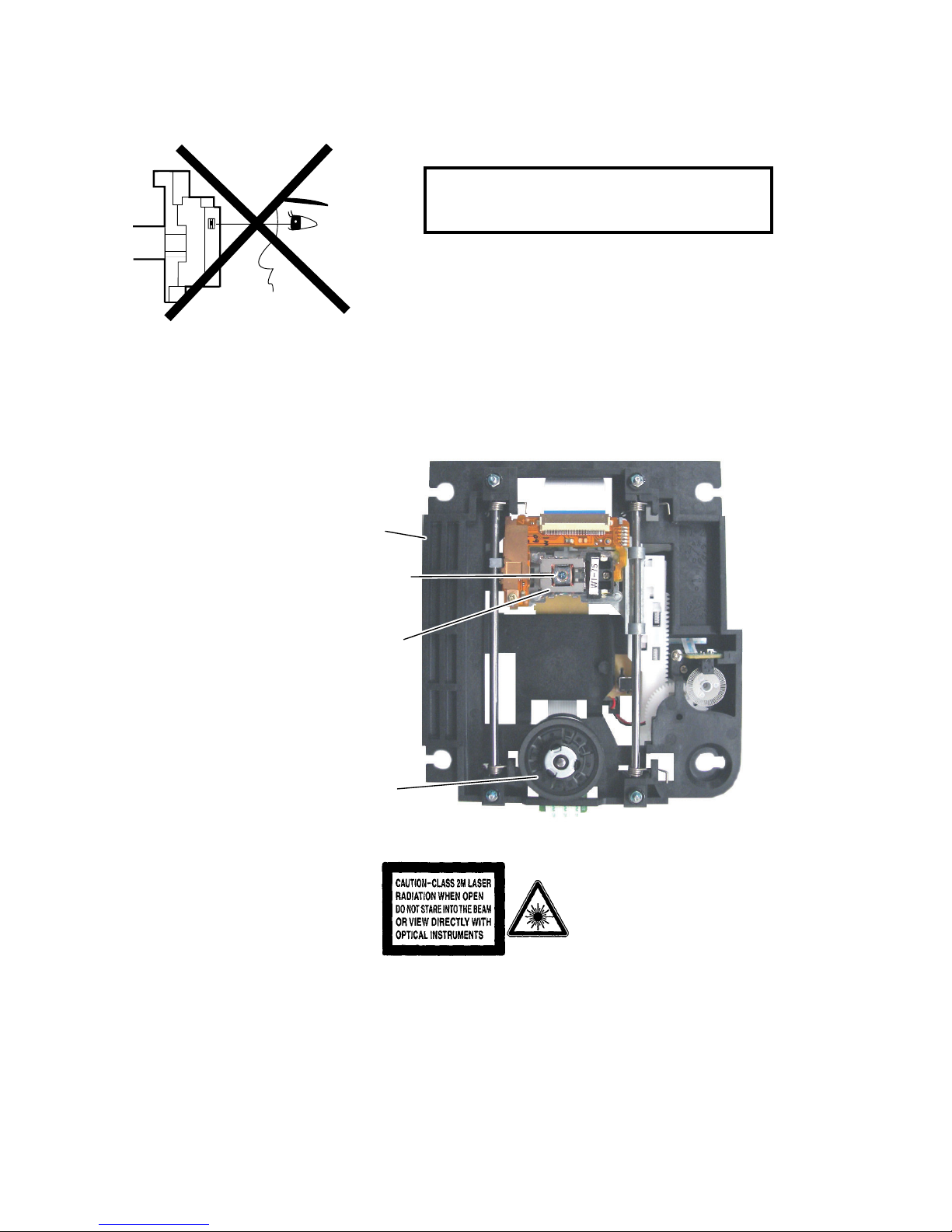
This DVD player uses a pickup that emits a laser beam.
The laser beam is emitted from the location shown in the figure. When checking the laser diode, be sure to keep
your eyes at least 30 cm away from the pickup lens when the diode is turned on. Do not look directly at the laser
beam.
CAUTION: Use of controls and adjustments, or doing procedures other than those specified herein, may result in
hazardous radiation exposure.
Location: Inside Top of DVD mechanism.
Do not look directly at the laser beam coming
from the pickup or allow it to strike against your
skin.
Drive Mechanism Assembly
Laser Beam Radiation
Laser Pickup
Turntable
Downloaded from www.Manualslib.com manuals search engine

1-3-1 DVD_SFNP
IMPORTANT SAFETY PRECAUTIONS
Product Safety Notice
Some electrical and mechanical parts have special
safety-related characteristics which are often not evi-
dent from visual inspection, nor can the protection
they give necessarily be obtained by replacing them
with components rated for higher voltage, wattage,
etc. Parts that have special safety characteristics are
identified by a ! on schematics and in parts lists. Use
of a substitute replacement that does not have the
same safety characteristics as the recommended
replacement part might create shock, fire, and/or other
hazards. The Product’s Safety is under review continu-
ously and new instructions are issued whenever
appropriate. Prior to shipment from the factory, our
products are carefully inspected to confirm with the
recognized product safety and electrical codes of the
countries in which they are to be sold. However, in
order to maintain such compliance, it is equally impor-
tant to implement the following precautions when a set
is being serviced.
Precautions during Servicing
A. Parts identified by the ! symbol are critical for
safety. Replace only with part number specified.
B. In addition to safety, other parts and assemblies
are specified for conformance with regulations
applying to spurious radiation. These must also be
replaced only with specified replacements.
Examples: RF converters, RF cables, noise block-
ing capacitors, and noise blocking filters, etc.
C. Use specified internal wiring. Note especially:
1)Wires covered with PVC tubing
2)Double insulated wires
3)High voltage leads
D. Use specified insulating materials for hazardous
live parts. Note especially:
1)Insulation tape
2)PVC tubing
3)Spacers
4)Insulators for transistors
E. When replacing AC primary side components
(transformers, power cord, etc.), wrap ends of
wires securely about the terminals before solder-
ing.
F. Observe that the wires do not contact heat produc-
ing parts (heatsinks, oxide metal film resistors, fus-
ible resistors, etc.).
G. Check that replaced wires do not contact sharp
edges or pointed parts.
H. When a power cord has been replaced, check that
5 - 6 kg of force in any direction will not loosen it.
I. Also check areas surrounding repaired locations.
J. Be careful that foreign objects (screws, solder
droplets, etc.) do not remain inside the set.
K. Crimp type wire connector
The power transformer uses crimp type connectors
which connect the power cord and the primary side
of the transformer. When replacing the transformer,
follow these steps carefully and precisely to pre-
vent shock hazards.
Replacement procedure
1)Remove the old connector by cutting the wires at a
point close to the connector.
Important: Do not re-use a connector. (Discard it.)
2)Strip about 15 mm of the insulation from the ends
of the wires. If the wires are stranded, twist the
strands to avoid frayed conductors.
3)Align the lengths of the wires to be connected.
Insert the wires fully into the connector.
4)Use a crimping tool to crimp the metal sleeve at its
center. Be sure to crimp fully to the complete clo-
sure of the tool.
L. When connecting or disconnecting the internal
connectors, first, disconnect the AC plug from the
AC outlet.
Downloaded from www.Manualslib.com manuals search engine
1-3-2 DVD_SFNP
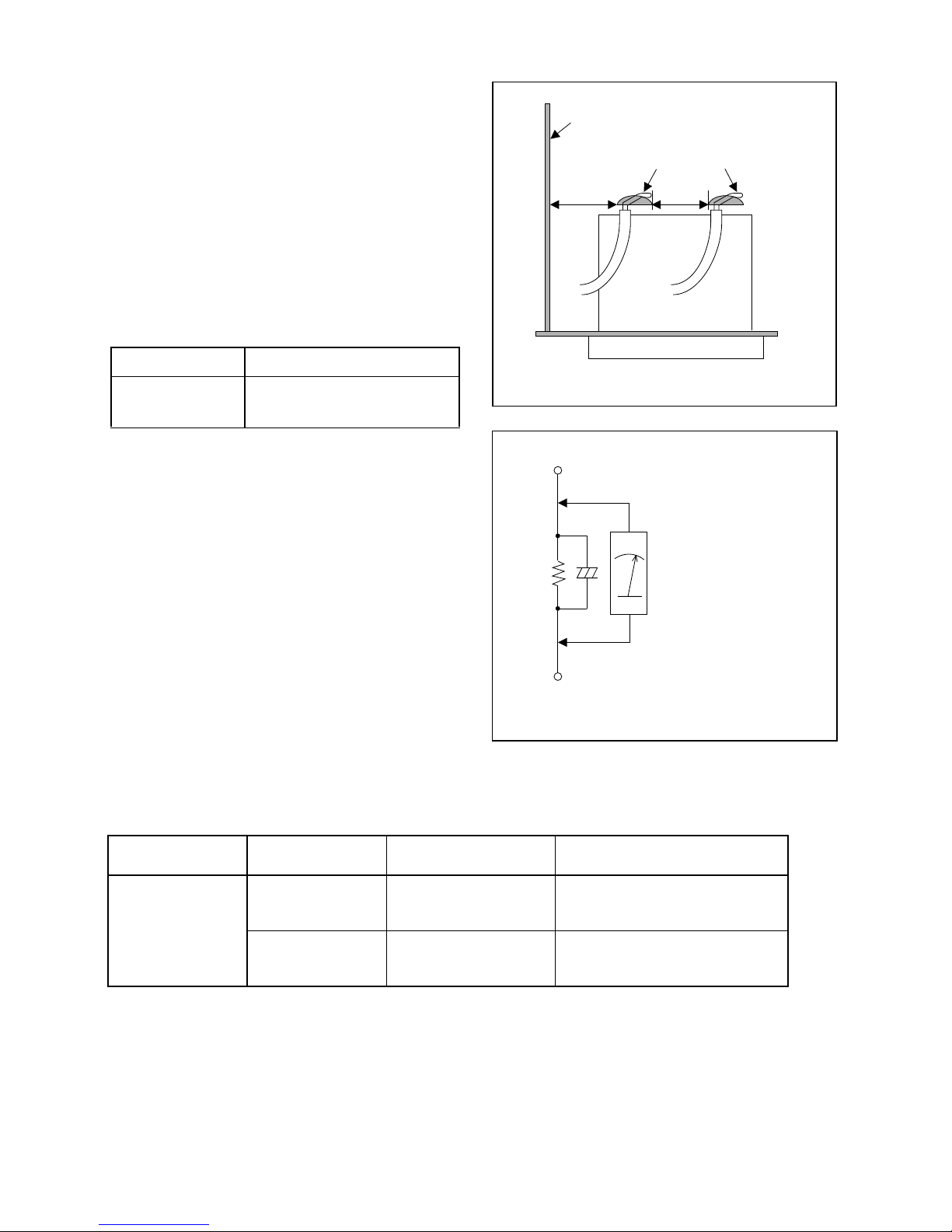
Fig. 1
Chassis or Secondary Conductor
Primary Circuit
d' d
AC Voltmeter
(High Impedance)
Exposed Accessible Part
B
One side of
Power Cord Plug Prongs
Z
Fig. 2
Safety Check after Servicing
Examine the area surrounding the repaired location
for damage or deterioration. Observe that screws,
parts, and wires have been returned to their original
positions. Afterwards, do the following tests and con-
firm the specified values to verify compliance with
safety standards.
1. Clearance Distance
When replacing primary circuit components, confirm
specified clearance distance (d) and (d’) between sol-
dered terminals, and between terminals and surround-
ing metallic parts. (See Fig. 1)
Table 1 : Ratings for selected area
Note: This table is unofficial and for reference only.
Be sure to confirm the precise values.
2. Leakage Current Test
Confirm the specified (or lower) leakage current
between B (earth ground, power cord plug prongs)
and externally exposed accessible parts (RF termi-
nals, antenna terminals, video and audio input and
output terminals, microphone jacks, earphone jacks,
etc.) is lower than or equal to the specified value in the
table below.
Measuring Method (Power ON) :
Insert load Z between B (earth ground, power cord
plug prongs) and exposed accessible parts. Use an
AC voltmeter to measure across the terminals of load
Z. See Fig. 2 and the following table.
AC Line Voltage Clearance Distance (d), (d’)
220 to 240 V
≥ 3 mm(d)
≥ 6 mm(d’)
Table 2: Leakage current ratings for selected areas
Note: This table is unofficial and for reference only. Be sure to confirm the precise values.
AC Line Voltage Load Z Leakage Current (i)
One side of power cord plug
prongs (B) to:
220 to 240 V
2kΩ RES.
Connected in
parallel
i≤0.7mA AC Peak
i≤2mA DC
RF or
Antenna terminals
50kΩ RES.
Connected in
parallel
i≤0.7mA AC Peak
i≤2mA DC
A/V Input, Output
Downloaded from www.Manualslib.com manuals search engine
1-4-1 DVDP_SN
STANDARD NOTES FOR SERVICING
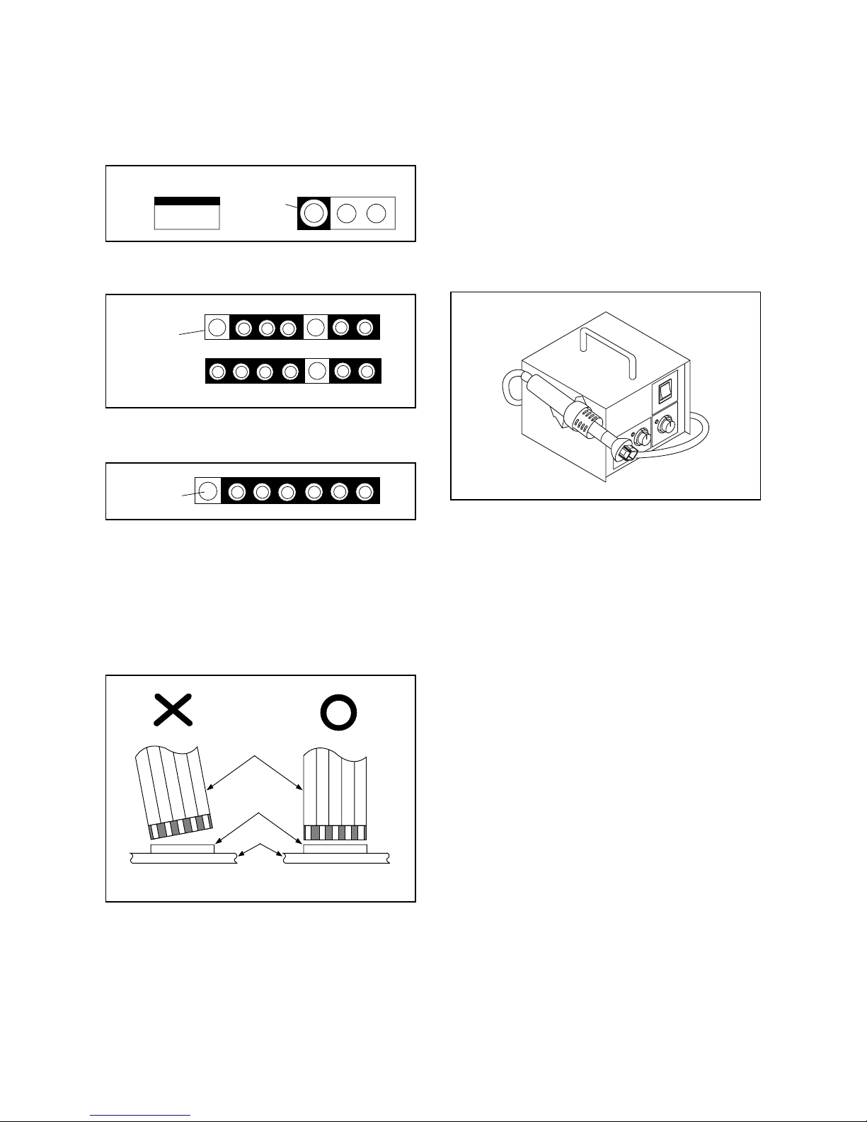
Circuit Board Indications
1. The output pin of the 3 pin Regulator ICs is
indicated as shown.
2. For other ICs, pin 1 and every fifth pin are
indicated as shown.
3. The 1st pin of every male connector is indicated as
shown.
Instructions for Connectors
1. When you connect or disconnect the FFC (Flexible
Foil Connector) cable, be sure to first disconnect
the AC cord.
2. FFC (Flexible Foil Connector) cable should be
inserted parallel into the connector, not at an
angle.
Pb (Lead) Free Solder
When soldering, be sure to use the Pb free solder.
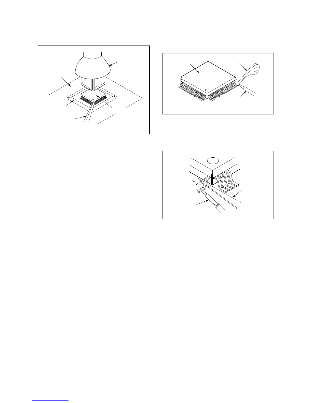
How to Remove / Install Flat Pack-IC
1. Removal
With Hot-Air Flat Pack-IC Desoldering Machine:
1. Prepare the hot-air flat pack-IC desoldering
machine, then apply hot air to the Flat Pack-IC
(about 5 to 6 seconds). (Fig. S-1-1)
2. Remove the flat pack-IC with tweezers while
applying the hot air.
3. Bottom of the flat pack-IC is fixed with glue to the
CBA; when removing entire flat pack-IC, first apply
soldering iron to center of the flat pack-IC and heat
up. Then remove (glue will be melted). (Fig. S-1-6)
4. Release the flat pack-IC from the CBA using
tweezers. (Fig. S-1-6)
CAUTION:
1. The Flat Pack-IC shape may differ by models. Use
an appropriate hot-air flat pack-IC desoldering
machine, whose shape matches that of the Flat
Pack-IC.
2. Do not supply hot air to the chip parts around the
flat pack-IC for over 6 seconds because damage
to the chip parts may occur. Put masking tape
around the flat pack-IC to protect other parts from
damage. (Fig. S-1-2)
Top View
Out
In
Bottom View
Input
5
10
Pin 1
Pin 1
FFC Cable
Connector
CBA
* Be careful to avoid a short circuit.
Fig. S-1-1
Downloaded from www.Manualslib.com manuals search engine
1-4-2 DVDP_SN
3. The flat pack-IC on the CBA is affixed with glue, so
be careful not to break or damage the foil of each
pin or the solder lands under the IC when
removing it.
With Soldering Iron:
1. Using desoldering braid, remove the solder from
all pins of the flat pack-IC. When you use solder
flux which is applied to all pins of the flat pack-IC,
you can remove it easily. (Fig. S-1-3)
2. Lift each lead of the flat pack-IC upward one by
one, using a sharp pin or wire to which solder will
not adhere (iron wire). When heating the pins, use
a fine tip soldering iron or a hot air desoldering
machine. (Fig. S-1-4)
3. Bottom of the flat pack-IC is fixed with glue to the
CBA; when removing entire flat pack-IC, first apply
soldering iron to center of the flat pack-IC and heat
up. Then remove (glue will be melted). (Fig. S-1-6)
4. Release the flat pack-IC from the CBA using
tweezers. (Fig. S-1-6)
Hot-air
Flat Pack-IC
Desoldering
Machine
CBA
Flat Pack-IC
Tweezers
Masking
Tape
Fig. S-1-2
Flat Pack-IC
Desoldering Braid
Soldering Iron
Fig. S-1-3
Fine Tip
Soldering Iron
Sharp
Pin
Fig. S-1-4
Downloaded from www.Manualslib.com manuals search engine
1-4-3 DVDP_SN
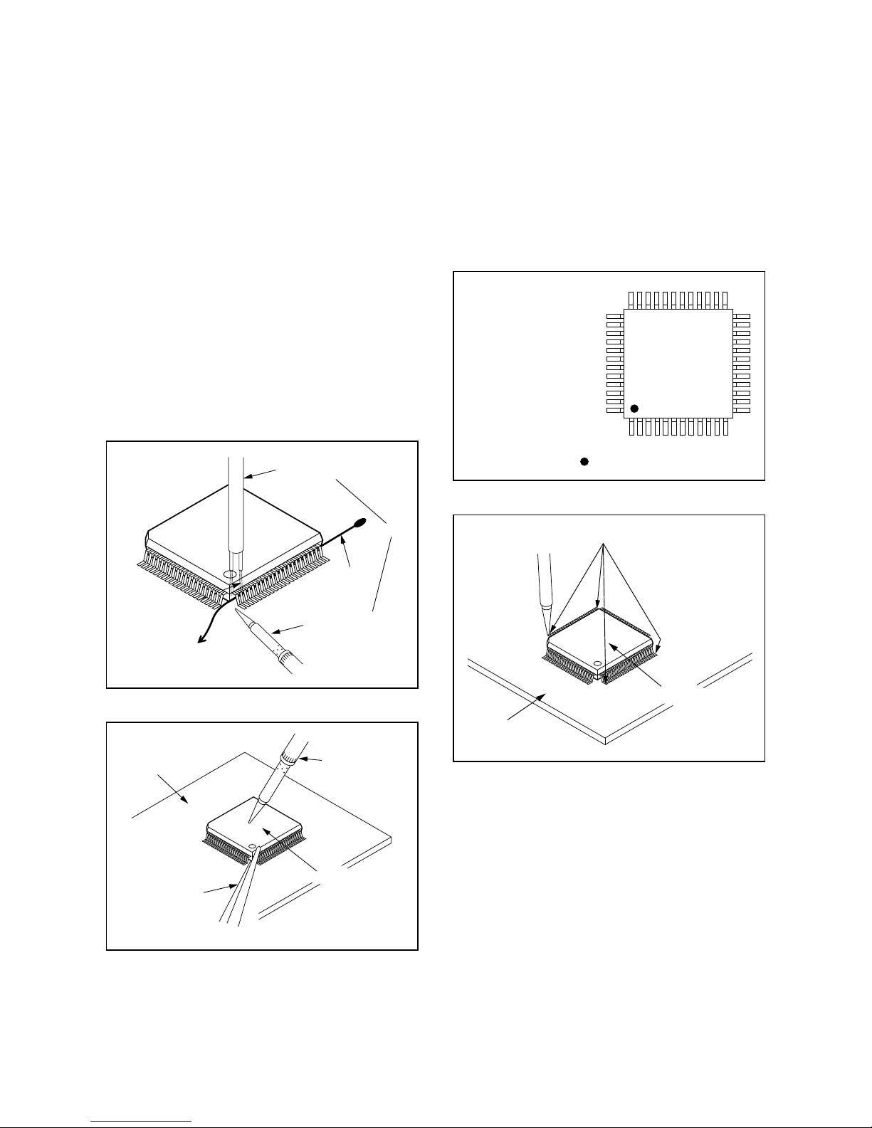
With Iron Wire:
1. Using desoldering braid, remove the solder from
all pins of the flat pack-IC. When you use solder
flux which is applied to all pins of the flat pack-IC,
you can remove it easily. (Fig. S-1-3)
2. Affix the wire to a workbench or solid mounting
point, as shown in Fig. S-1-5.
3. While heating the pins using a fine tip soldering
iron or hot air blower, pull up the wire as the solder
melts so as to lift the IC leads from the CBA
contact pads as shown in Fig. S-1-5.
4. Bottom of the flat pack-IC is fixed with glue to the
CBA; when removing entire flat pack-IC, first apply
soldering iron to center of the flat pack-IC and heat
up. Then remove (glue will be melted). (Fig. S-1-6)
5. Release the flat pack-IC from the CBA using
tweezers. (Fig. S-1-6)
Note: When using a soldering iron, care must be
taken to ensure that the flat pack-IC is not
being held by glue. When the flat pack-IC is
removed from the CBA, handle it gently
because it may be damaged if force is applied.
2. Installation
1. Using desoldering braid, remove the solder from
the foil of each pin of the flat pack-IC on the CBA
so you can install a replacement flat pack-IC more
easily.
2. The “●” mark on the flat pack-IC indicates pin 1.
(See Fig. S-1-7.) Be sure this mark matches the 1
on the PCB when positioning for installation. Then
presolder the four corners of the flat pack-IC. (See
Fig. S-1-8.)
3. Solder all pins of the flat pack-IC. Be sure that
none of the pins have solder bridges.
To Solid
Mounting Point
Soldering Iron
Iron Wire
or
Hot Air Blower
Fig. S-1-5
Fine Tip
Soldering Iron
CBA
Flat Pack-IC
Tweezers
Fig. S-1-6
Example :
Pin 1 of the Flat Pack-IC
is indicated by a " " mark.
Fig. S-1-7
Presolder
CBA
Flat Pack-IC
Fig. S-1-8
Downloaded from www.Manualslib.com manuals search engine
1-4-4 DVDP_SN
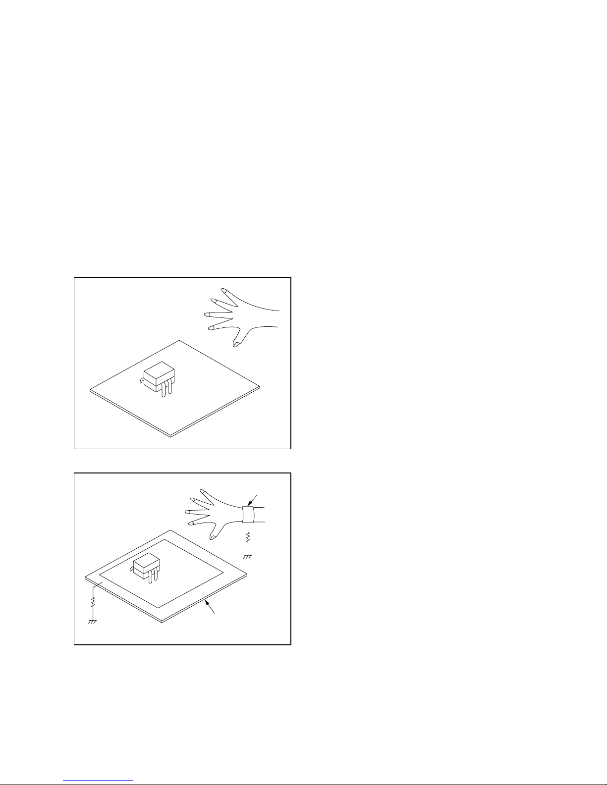
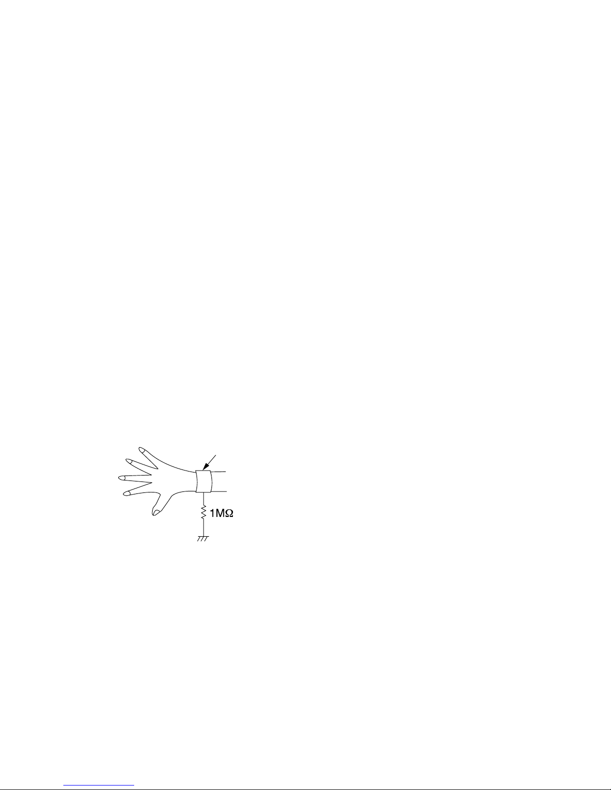
Instructions for Handling Semi-
conductors
Electrostatic breakdown of the semi-conductors may
occur due to a potential difference caused by
electrostatic charge during unpacking or repair work.
1. Ground for Human Body
Be sure to wear a grounding band (1 MΩ) that is
properly grounded to remove any static electricity that
may be charged on the body.
2. Ground for Workbench
Be sure to place a conductive sheet or copper plate
with proper grounding (1 MΩ) on the workbench or
other surface, where the semi-conductors are to be
placed. Because the static electricity charge on
clothing will not escape through the body grounding
band, be careful to avoid contacting semi-conductors
with your clothing.
<Incorrect>
CBA
Grounding Band
Conductive Sheet or
Copper Plate
1MΩ
1MΩ
<Correct>
CBA
Downloaded from www.Manualslib.com manuals search engine
1-5-1 DHD_SN
HANDLING PRECAUTIONS FOR HDD
CAUTION:
1. SHOCK
a. Exposing HDD to shock may be the biggest
damaging factor. Please note that HDD is easily
damaged even if dropped from any height. Be sure
to place HDD on a shock-absorbent mat. Also, be
careful when transporting HDD.
b. Be careful not to subject HDD to any shock when
tightening screws for HDD replacement.
(Tighten screws manually, not with an electric
driver.)
2. MOISTURE
a. Moisture may also be a damaging factor. HDD is
semiclosed style. Sudden changes in ambient
temperature may cause moisture to form. Monitor
temperature and do not allow moisture to form on
the media surface. Also, when opening HDD
package, do so only after package is at ambient
temperature.
b. After replacing HDD, leave it to reach room
temperature (about 2 hours) for preventing dew
internal condensation, and then work necessary
task such as operation check.
3. STATIC ELECTRICITY
a. After removing HDD or taking replacement HDD
out of the protective bag (the replacement HDD is
packed in a protective bag), place HDD on a
conductive surface. A grounding band should be
worn when handling.
Both the conductive surface and grounding band
should be grounded.
b. Make sure that HDD is placed on main unit
completely and then let go of it, when assembling.
c. Do not put HDD on a packing bag. (for preventing
electrostatic damage)
4. OTHERS
a. Be careful so as not to do the followings.
Otherwise, HDD might be damaged.
- DO NOT disassemble HDD.
- When handling HDD, be sure to hold both sides
securely.
b. HDD should be stored, packed in the protective
bag, in suitable surroundings (i.e., no extreme
changes in temperature to avoid condensation).
c. When transporting HDD, be sure to use the
exclusive packing case (the replacement HDD
carton).
d. Do not stack HDDs.
e. Do not place vertically because HDD is unstable
and easy to fall.
Grounding Band
Downloaded from www.Manualslib.com manuals search engine
1-6-1 E2B21DC
CABINET DISASSEMBLY INSTRUCTIONS
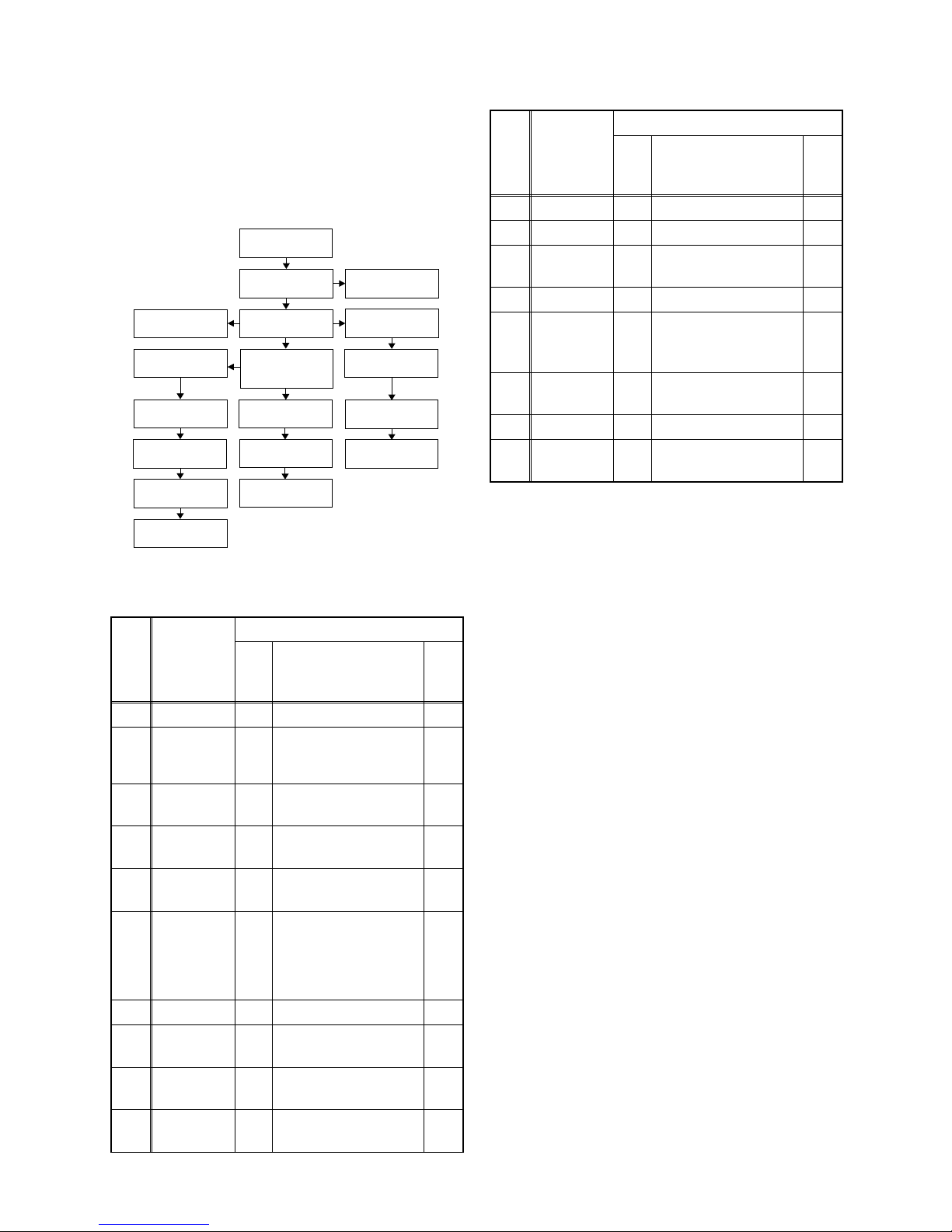
1. Disassembly Flowchart
This flowchart indicates the disassembly steps to gain
access to item(s) to be serviced. When reassembling,
follow the steps in reverse order. Bend, route, and
dress the cables as they were originally.
2. Disassembly Method
Note:
(1): Identification (location) No. of parts in the figures
(2): Name of the part
(3): Figure Number for reference
(4): Identification of parts to be removed, unhooked,
unlocked, released, unplugged, unclamped, or
desoldered.
P=Spring, L=Locking Tab, S=Screw,
CN=Connector
*=Unhook, Unlock, Release, Unplug, or Desolder
e.g. 6(S-1) = six Screws (S-1),
5(L-1) = five Locking Tabs (L-1)
(5): Refer to “Reference Notes.”
ID/
LOC.
No.
PART
REMOVAL
Fig.
No.
REMOVE/*UNHOOK/
UNLOCK/RELEASE/
UNPLUG/DESOLDER
Note
[1] Top Cover D1 8(S-1) ---
[2] Front Unit D2
CN1641, *5(L-1),
*3(L-2)
1
1-1
1-2
[3]
Front
Assembly
D3 ---------- ---
[4]
CONTROL
CBA
D3 *3(L-3) 1-3
[5]
HDD
Assembly
D4
*CN651, *CN1015,
4(S-2)
---
[6]
DVD
Mechanism
&
DVD/HDD
MAIN CBA
Assembly
D4
2(S-3), 4(S-4),
*CN101, *CN701,
Locking Card Spacer,
Attachment Holder
2
[7] ATA CBA D5 CN3001 ---
[8]
HDD
Bracket
D5 4(S-5) ---
[9] HDD D5
(S-6), HDD Plate
Earth
---
[10]
Rear Panel
Unit
D6
*CN1601, 5(S-7),
2(S-8)
---
[1] Top Cover
[2] Front Unit
[3] Front Assembly
[4] CONTROL
CBA
[18] Front
Bracket R
[5] HDD Assembly
[9] HDD
[8] HDD Bracket
[6] DVD Mechanism
& DVD/HDD MAIN
CBA Assembly
[15] POWER
SUPPLY CBA
[16] Power Holder
[12] Fan Cover
[13] DC Fan Motor
[14] Rear Panel
[10] Rear Panel
Unit
[11] JACK CBA
[17] AV CBA
[7] ATA CBA
[11] JACK CBA D6 *CN1802, Desolder ---
[12] Fan Cover D7 2(S-9) ---
[13]
DC Fan
Motor
D7 Fan Earth ---
[14] Rear Panel D7 ---------- ---
[15]
POWER
SUPPLY
CBA
D8 *CN1151, 4(S-10) ---
[16]
Power
Holder
D8 ---------- ---
[17] AV CBA D8 2(S-11) ---
[18]
Front
Bracket R
D8 (S-12) ---
↓
(1)
↓
(2)
↓
(3)
↓
(4)
↓
(5)
ID/
LOC.
No.
PART
REMOVAL
Fig.
No.
REMOVE/*UNHOOK/
UNLOCK/RELEASE/
UNPLUG/DESOLDER
Note
Downloaded from www.Manualslib.com manuals search engine
1-6-2 E2B21DC
Reference Notes
1. Locking Tabs (L-1) ,(L-2) and (L-3) are fragile. Be
careful not to break them.
1-1. Release five Locking Tabs (L-1).
1-2. Release three Locking Tabs (L-2) and
remove the Front Assembly.
1-3. Release three Locking Tabs (L-3).
2. Do not replace the DVD Mechanism or the DVD/
HDD MAIN CBA Assembly separately, when
replacing the DVD Mechanism & DVD/HDD MAIN
CBA Assembly. Order the new DVD Mechanism &
DVD/HDD MAIN CBA Assembly.
2-1. Whenever you have replaced the HDD unit,
initialize the HDD unit. To initialize the HDD
unit, perform the following.To put the HDD &
DVD into the HDD mode, press the [HDD]
button on the remote control unit.
2-2. To put the HDD & DVD into the self-check
mode, after pressing [VARIABLE SKIP]
button, press the [3], [6], and [9] buttons on
the remote control in that order within three
seconds.
2-3. Press [ENTER] button. The HDD & DVD is
initialized and the power is turned off
automatically after two seconds.
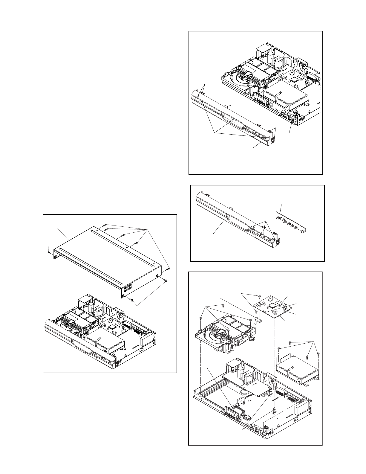
(S-1)
(S-1)
(S-1)
[1] Top Cover
Fig. D1
Fig. D2
[2] Front Unit
(L-1)
CN1641
(L-1)
(L-1)
(L-2)
Fig. D3
[3] Front Assembly
[4] CONTROL CBA
(L-3)
(S-2)
CN651
CN701
CN101
CN1015
(S-3)
(S-4)
Fig. D4
[5] HDD
Assembly
[6] DVD Mechanism
& DVD/HDD MAIN
CBA Assembly
Locking Card Spacer
Attachment
Holder
Downloaded from www.Manualslib.com manuals search engine
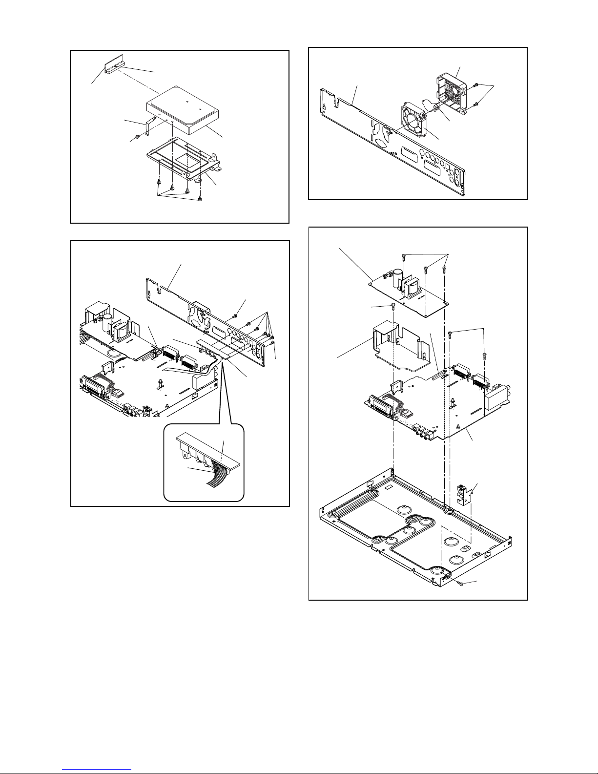
1-6-3 E2B21DC
Fig. D5
[9] HDD
[7] ATA CBA
[8] HDD Bracket
(S-5)
(S-6)
CN3001
HDD Plate Earth
CN1802
Fig. D6
[10] Rear Panel Unit
[11] JACK
CBA
Desolder
Lead
with
blue
stripe
CN1601
(S-7)
(S-8)
(S-8)
Fig. D7
[14] Rear Panel
[12] Fan Cover
[13] DC Fan Motor
(S-9)
Fan Earth
Fig. D8
[15] POWER SUPPLY CBA
[16] Power
Holder
[17] AV CBA
[18] Front
Bracket R
(S-10)
(S-10)
(S-12)
(S-11)
CN1151
Downloaded from www.Manualslib.com manuals search engine
1-7-1 E2B21INT
HOW TO SELF-CHECK AND INITIALIZE THE HDD & DVD
1. Turn on the HDD & DVD.
2. To put the HDD & DVD into the HDD mode, press [HDD] on the remote control unit.
3. To put the HDD & DVD into the self-check mode, after pressing [VARIABLE SKIP] button, press the [3], [6],
and [9] buttons on the remote control in that order within three seconds.
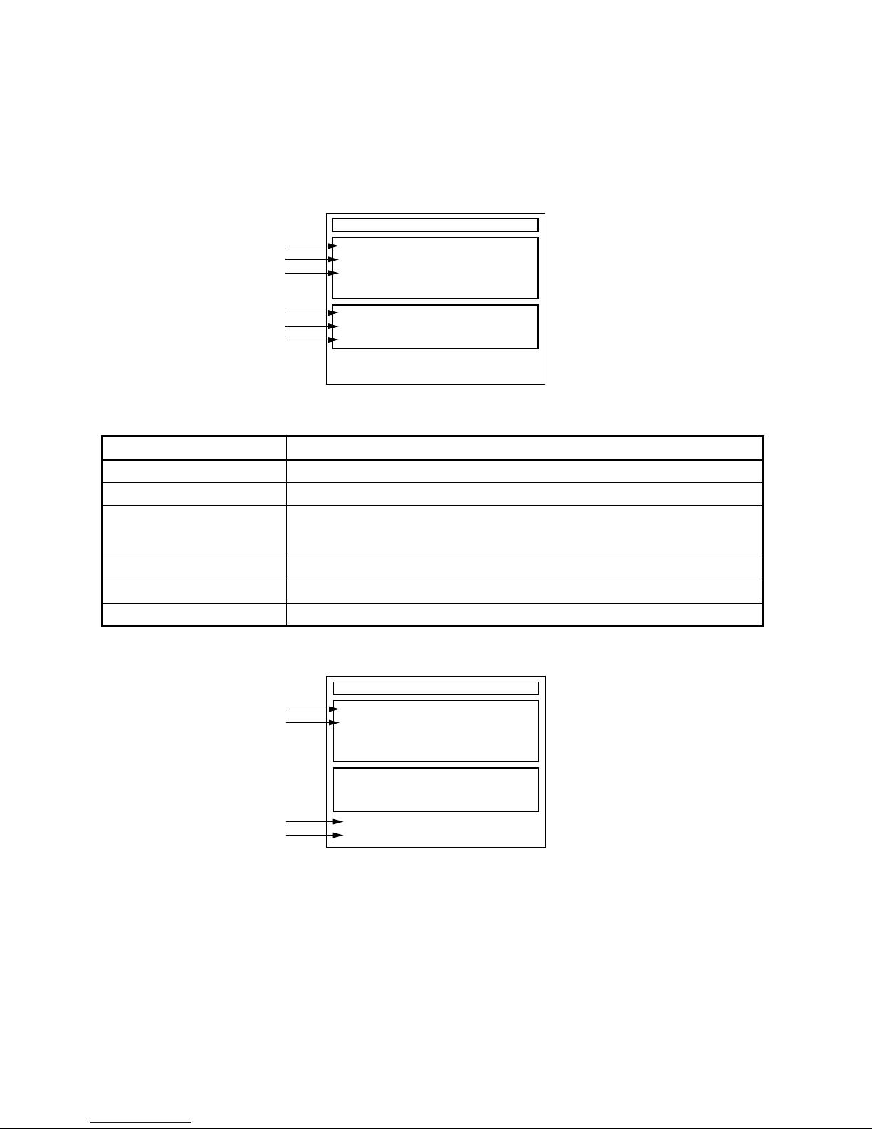
Fig. a appears on the screen and all LEDs light.
Fig. a: Self-Check Mode Screen
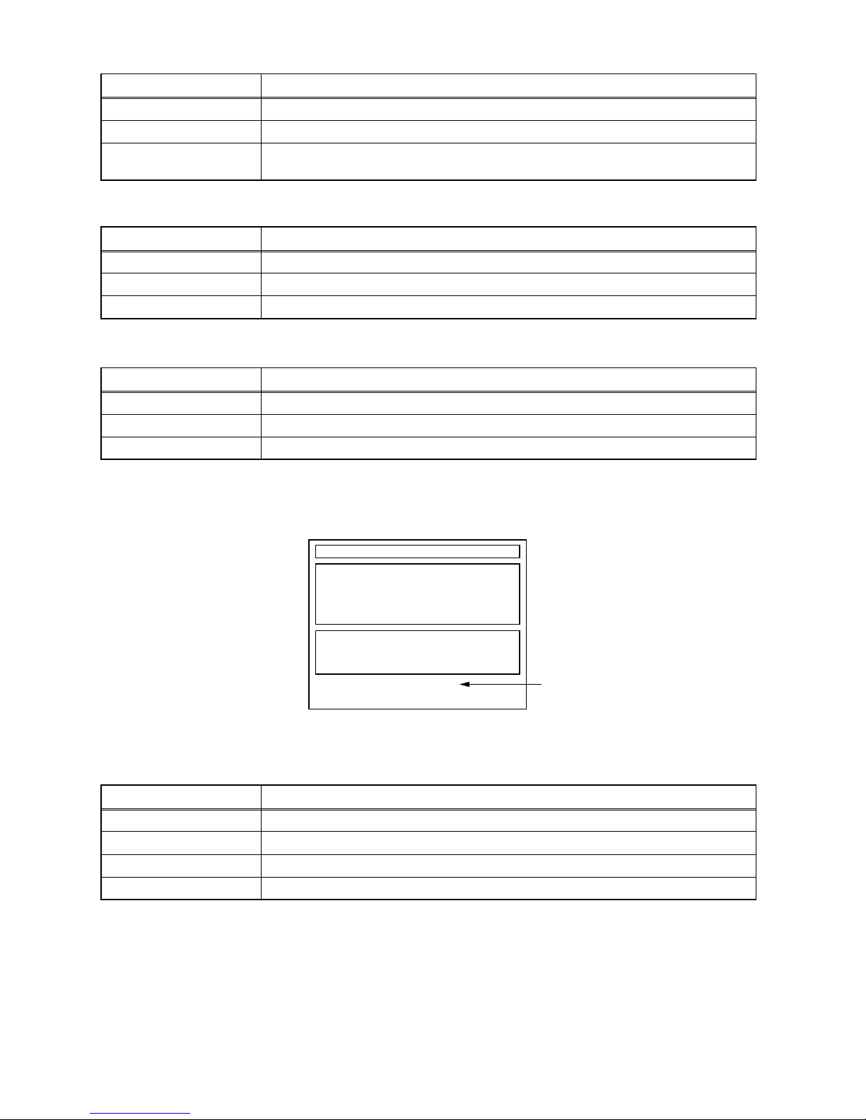
4. Upon the self-check completion, Fig. b appears on the screen.
Fig. b: Screen of Finishing Self-Check Mode
Table 1: Description of Fig. a
INDICATION DESCRIPTION
DVD CONNECT STATUS (*1) Connecting Condition of DVD(F/E)
HDD CONNECT STATUS (*2) Connecting Condition of HDD
HDD POWER ON HOURS (*3)
Value of HDD power on hours obtained from S.M.A.R.T. command. (If not obtainable,
value of HDD power on hours is “0”.)
Value in parentheses is the factory setting value. (If no setting, the value is “0”.)
BE Ver. (*4) B/E version
FE Ver. (*5) F/E version
Sub Micon Ver. (*6) Sub micro controller version
Self-Analysys and Report
DVD CONNECT STATUS :
HDD CONNECT STATUS :
HDD POWER ON HOURS :
BE Ver. :
FE Ver. :
Sub Micon Ver. :
T2*******Q2J
R20_0**_***h
NFQ2***T1-3N11
*1
*2
*3
*4
*5
*6
"
*******
" differs depending on the models.
Self-Analysys and Report
DVD CONNECT STATUS : OK
HDD CONNECT STATUS : OK
HDD POWER ON HOURS : 100(40)
*7
*8
*9
*10
BE Ver. :
FE Ver. :
Sub Micon Ver. :
FACTORY DEFAULT :
POWER OFF :
ENTER
POWER
T2*******Q2J
R20_0**_***h
NFQ2***T1-3N11
"
*******
" differs depending on the models.
Downloaded from www.Manualslib.com manuals search engine
1-7-2 E2B21INT
5. When the self-check mode is complete, press [STANDBY-ON] button to turn the power off.
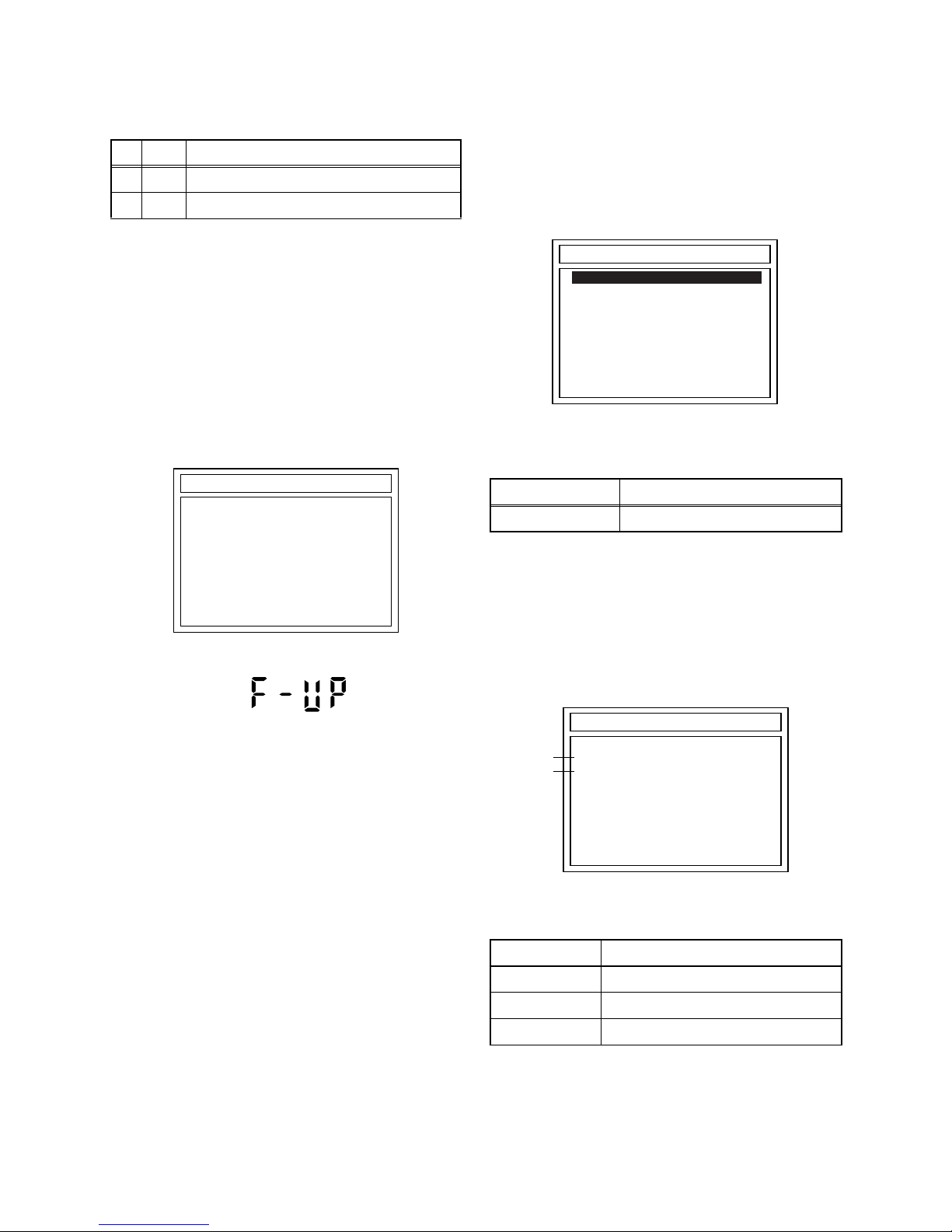
When initializing the HDD & DVD, press [ENTER] button. Fig. c appears on the screen. After two seconds, the
power is turned off automatically.
Fig. c: Initialize Mode Screen
NOTE: When initializing, “Current Clock”, “Setup Changing Item”, “Channel Setup”, “Area Setup”, “Program” and
“HDD Contents” are initialized.
Table 2: Indication of DVD self-check (*7)
INDICATION DESCRIPTION
OK Connection of DVD is normal.
NOT FOUND DVD drive cannot be found.
CABLE ERROR
FFC cable (connecting to CN401) between the DVD drive and the DVD/HDD MAIN CBA is
not connected correctly.
Table 3: Indication of HDD self-check (*8)
INDICATION DESCRIPTION
OK Connection of HDD is normal.
NOT FOUND HDD drive cannot be found.
CABLE ERROR FFC cable between the ATA CBA and the HDD drive is not connected correctly.
Table 4: Available button in self-check mode
BUTTON DESCRIPTION
ENTER (*9) Initialize (only when the self-check mode is complete)
STANDBY-ON (*10) Turn the power off (when the self-check mode is complete)
OTHER Not available
Table 5: Description of *11 in Fig. c
INDICATION DESCRIPTION
ENTER Initialization preparation is complete.
WRITING Initializing
OK Initializing is finished normally.
NG Initializing is not finished normally.
"
*******
" differs depending on the models.
Self-Analysys and Report
DVD CONNECT STATUS : OK
HDD CONNECT STATUS : OK
HDD POWER ON HOURS : 100(40)
BE Ver. :
FE Ver. :
Sub Micon Ver. :
T2*******Q2J
R20_0**_***h
NFQ2***T1-3N11
FACTORY DEFAULT : *11WRITING
Downloaded from www.Manualslib.com manuals search engine
1-8-1 E2B21FW
FIRMWARE RENEWAL MODE
1. Update Contents
2. Update
1. Turn the power on and remove the disc in the tray.
2. To switch the HDD & DVD into the HDD mode,
press [HDD] on the remote control unit.
3. To put the HDD & DVD into version up mode,
press [VARIABLE SKIP] and [6], [5], [4] buttons on
the remote control unit in that order within 3
seconds. The tray will open automatically.
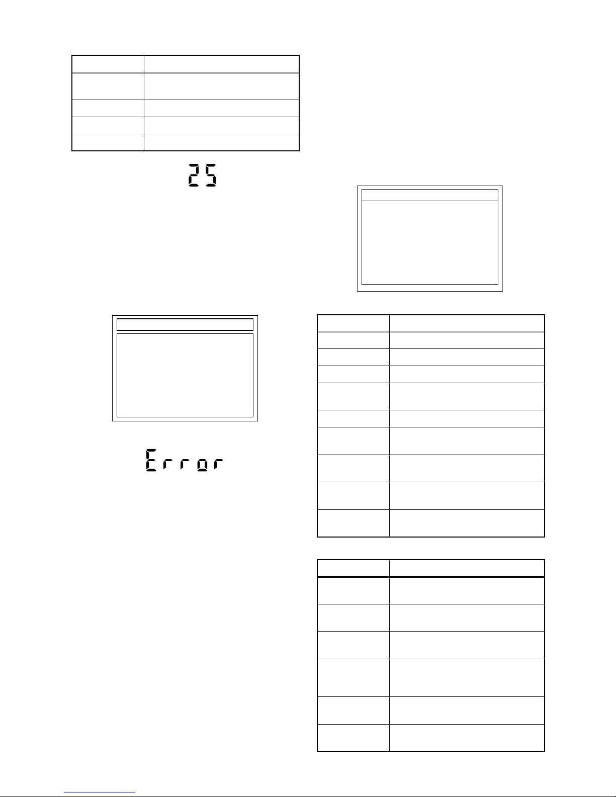
Fig. a appears on the TV screen and Fig. b
appears on the VFD.
Fig. a: Update Mode TV Screen
Fig. b: VFD Display in Update Mode
4. Load the update disc.
The TV screen will display Fig. c.
- If the update disc contains only a single file, the
update will initiate automatically when the disc is
inserted.
Fig. c: Update Disc TV Screen
Effective FIRMWARE update files will have the file
extensions shown below.
5. Select the desired FIRMWARE to be updated with
the arrow button and press the [ENTER] or [PLAY]
button.
The tray will open automatically; close the tray by
pressing [OPEN/CLOSE] button or by hand.
6. Fig. d appears on the TV screen and Fig. e
appears on the VFD, and the update will start.
Fig. d: TV Display during update
The status displayed in *1 is as shown below.
Item Status
1 B/E Update B/E FIRMWARE
2 F/E Update F/E FIRMWARE
DISC UPDATE
Please Insert F/W Disc
*FIRMWARE version will differ depending on the
model. Fig. a is an example.
File extension Status
MOT F/E FIRMWARE file
Display Status
B/E FIRMWARE B/E
F/E FIRMWARE F/E
UNKNOWN Not FIRMWARE B/E or F/E
DISC UPDATE
<DIR> BE
<DIR> FE
H3T00141B2C.MOT
*FIRMWARE version will differ depending on the
model. Fig. c is an example.
*1
*2
DISC UPDATE
DISC UPDATING
TARGET: B/E
STATUS: EXECUTING
*FIRMWARE version will differ depending on the
model. Fig. d is an example.
Downloaded from www.Manualslib.com manuals search engine
1-8-2 E2B21FW
The status displayed in *2 is as shown below.
Fig. e: VFD Display during update
When the TV screen displays "Firmware
Updating... XX% Complete," the VFD will indicate
"XX"%.
7. When update is complete, the unit will shut off
automatically.
8. If an error occured during updating, the TV screen
will display Fig. f.
Fig. f: TV Display when completing update with error
Fig. h: VFD Display when completing update with error
In this case, all button operations will be invalid
except [STANDBY-ON] button.
9. Press [STANDBY-ON] button to turn the power off
and press [STANDBY-ON] button again to turn the
power back on and finish updating.
3. How to Verify the Firmware
Version
1. Turn the power on and remove the disc in the tray.
2. To switch the HDD & DVD into HDD mode, press
[HDD] on the remote control unit.
3. To put the HDD & DVD into version display mode,
press [VARIABLE SKIP] and [1], [2], [3] buttons on
the remote control unit in that order within 3
seconds. Fig. i appears on the TV screen.
Fig. i: Firmware version display
Effective buttons in this mode are the following...
Display Status
EXECUTING
Loading F/W from Update Disc or
writing to Flash memory
ERROR Error during Flash memory writing
FILE ERROR Check SAM error in F/W file
READ ERROR Error during F/W file reading
DISC UPDATE
PLEASE PUSH POWER BUTTON
TARGET: B/E
STATUS: ERROR
*FIRMWARE version will differ depending on the
model. Fig. f is an example.
Display Contents
MODEL NAME Product number
BE Ver. Firmware B/E version
FE Ver. Application F/E version
Sub Micon Ver.
Sub Microcontroller firmware
version
REGION Region code of playable DVD disc
CPRM KEY
NO.
CPRM key number
HDD MODEL
HDD serial number and capacity
(GByte)
LD
ADJUSTMENT
LD adjustment progress (done: OK/
not done: --)
DISC
ADJUSTMENT
Factory adjustment progress (done:
OK/not done: --)
Buttons Operations
POWER
Power off to release from this
mode.
SETUP
Version display disappears and
SETUP screen appears.
TOP MENU
Version display disappears and
TOP MENU screen appears.
TIMER PROG.
Version display disappears and
TIMER PROGRAMMING screen
appears.
DUBBING
MENU
Version display disappears and
DUBBING screen appears.
Others
While displaying version and
normal operation.
******* part will differ depending on the model.
Fig. i is an example.
VERSION INFORMATION
E2B10ED
H3T*****B2C
R34_***_**
T3007THP
2
(0x***)
***********(***GByte)
***
OK
OK
Model Name :
BE Ver. :
FE Ver :
Sub Micon Ver. :
REGION:
CPRM KEY NO:
HDD MODEL:
DivX Ver.:
LD ADJUSTMENT:
DISC ADJUSTMENT:
Downloaded from www.Manualslib.com manuals search engine
1-10-1
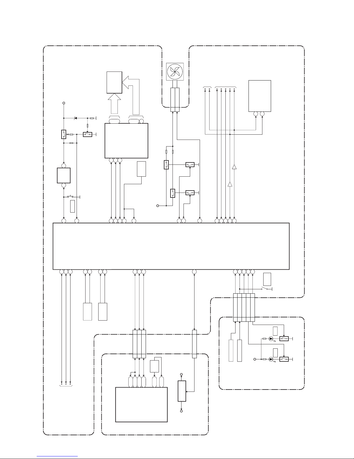
BLOCK DIAGRAMS
System Control Block Diagram
IC101
(MAIN MICRO CONTROLLER)
IC1501
(SUB MICRO CONTROLLER)
REMOTE
SENSOR
RM1501
1G
7G
~
23
17
~
a
h
i
~
7
14
~
GRID
RESET
VFD
SEGMENT
FL1501
IC1503
IC1502
(VFD DRIVER)
KEY SWITCH
KEY SWITCH
CN1641
CN1650
Q1653
D1653
DVD
16
28
1
2
1
2
100
82
83
70
69
68
22
77
21
20
26
25
23
36
35
N23
J25
T4
N24
13
15
11
12
74
1 2
10
27MHz
X'TAL
X802
CLK 27 IN
CLK 27 OUT
SYS-RESET
SYS-RESET
SUB-RXD
SUB-TXD
CN701
SYS-RESET
SUB-RXD
SUB-TXD
CN1201
REG-CONT
PWR-SW
AUDIO-MUTE
DVD/HDD-AUDIO-MUTE
DVD/HDD-AUDIO-MUTE
SCART-AUDIO-MUTE
SCART-AUDIO-MUTE
I2C-SDA
I2C-SCL
XOUT
XIN
XCOUT
XCIN
RESET
P-DOWN
FL-DIN
FL-CLK
FL-STB
REMOTE
REMOTE2
KEY-1
KEY-2
POWER-LED(NU)
HDD-LED
DVD-LED
REG-CONT
PWR-SW
SDA
SCL
AUDIO-MUTE
29
TO POWER SUPPLY
BLOCK DIAGRAM
TO AUDIO
BLOCK DIAGRAM
10MHz
X'TAL
X1502
32.768KHz
X'TAL
X1501
Q1111
Q1112
DIN
CLK
STB
2 FAN-LOCK
1 FAN
CN1601
FAN
N1
LOW-POW80
LOW-POW
SCL
SDA
TU1701(TUNER UNIT)
9
10
SYS+5V
RESET
SW1501
79
3
75
FAN-CONT1
Q1604
Q1603
EV+12V
Q1601
Q1506
Q1507
78
FAN-CONT2
87
FAN-LOCK
N2
44SYS-RESET
11SUB-RXD
33SUB-TXD
IC106
CN101 CN1151
24 1V2-CONT
VI+1.2VP-ON+1.2V
30 301V2-CONT
+1.2V
REGULATOR
Q1602
SDA
SCL
TO VIDEO
BLOCK DIAGRAM
KEY-2 55
POWER-LED(NU)
22
HDD-LED 66
DVD-LED 77
KEY-1 33
Q1652
D1652
HDD
SYS+5V
SW1643
OPEN
/CLOSE
AV CBA
DVD/HDD MAIN CBA
CONTROL CBA
E2B25BLS
Downloaded from www.Manualslib.com manuals search engine
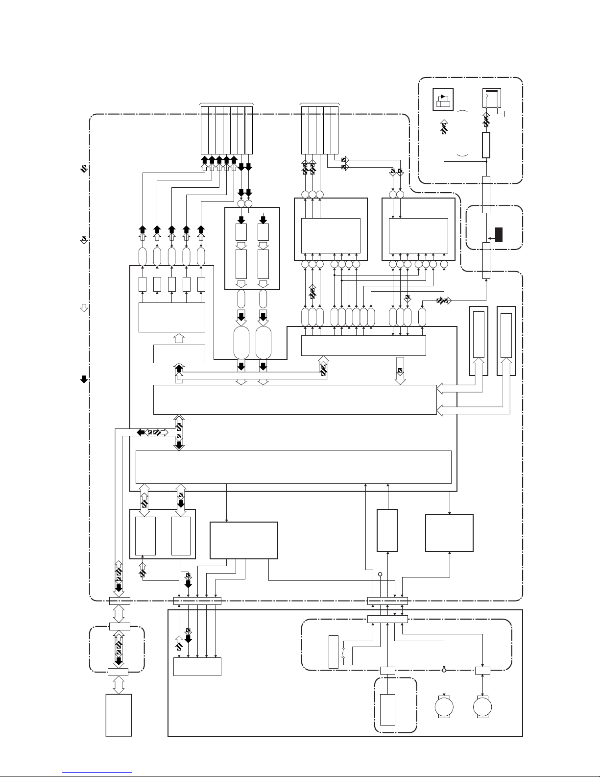
1-10-2
Digital Signal Process Block Diagram
IC101
FRONT-END
DIGITAL
SIGNAL
PROCESS
IC201
RF/
ERROR AMP
IC301
MOTOR
DRIVER
MOTOR
DRIVER
IC202
OP AMP
IC302
IC104 (FLASH MEMORY)
TO VIDEO
BLOCK
DIAGRAM
CN1201
TO AUDIO
BLOCK
DIAGRAM
CN1201
T2
M4
G4
L4
K1
G3
U1
R3
U2
P26
N26
M26
T3
P2
R1
P3
R2
R26
D/A
D/A
D/A
D/A
AUDIO
I/F
VIDEO
ENCODER
BACK-END
DIGITAL
SIGNAL
PROCESS
VIDEO
I/F
FLASH MEMORY
FE
ENCODER
TRAY OPEN
IC102,IC103 (DDR SDRAM)
DDR SDRAM
CN201
DVD MECHANISM
HARD DISK
DRIVE
TILT
TRACKING
FOCUS
PICK
-UP
SLED
MOTOR
M
REC VIDEO SIGNAL PB VIDEO SIGNAL REC AUDIO SIGNAL PB AUDIO SIGNAL
D/A
LPC
CN1001
CN701
CN1003
SPINDLE
MOTOR
M
CN1002
CN301
+3.3V
IC701 (VIDEO DECODER)
DECODER A/D45-50
Y2, AA4,
AB1-AB4
DECODER A/D39-44
V3, Y3, W1,
Y4, W2, AA3
10
13
VIDEO-Y(I/P)-OUT
24
VIDEO-Y(I)-OUT
30
VIDEO-C-OUT
22
VIDEO-C-IN 8
VIDEO-Cb/Pb-OUT
28
VIDEO-Cr/Pr-OUT
26
VIDEO-Y/CVBS-IN
10
IC801
(AUDIO D/A CONVERTER)
AUDIO D/A
CONVERTER
7
6
8
15
14
16
4
3
5
IC802
(AUDIO A/D CONVERTER)
AUDIO A/D
CONVERTER
7
8
9
13
14
6
2
L-CH
R-CH
MUTE
R-CH
L-CH
10
11
12
CN701
AUDIO(L)-OUT
14
AUDIO(R)-OUT
16
DVD/HDD-AUDIO-MUTE
12
AUDIO(L)-IN
20
AUDIO(R)-IN
18
28 28SPDIF
CN101 CN1151
CN1801
99SPDIF
CN1802
DIGITAL
AUDIO OUT
(COAXIAL)
JK1209
(REAR)
BUFFER
Q1803
WF7
CN3002 CN3001 CN651
DVD/HDD MAIN CBA
ATA CBA
RELAY CBA
JACK CBA
AV CBA
ENCODER CBA
JK1207
(REAR)
FIBER OPTIC
TRANS MODULE
DIGITAL
AUDIO OUT
(OPTICAL)
E2B25BLD
Downloaded from www.Manualslib.com manuals search engine
 Loading...