


 Loading...
Instruction Manual
Multi-function Keypad "TP-G1"
Thank you for purchasing our Multi-function Keypad TP-G1.
•This product is designed to remotely control the FRENIC-Eco series of inverters. Read through this instruction manual and be familiar with the handling procedure for correct use.
•Improper handling blocks correct operation or causes a short life or failure.
•Deliver this manual to the end user of the product. Keep this manual in a safe place until the Multi-function Keypad is discarded.
•For the usage of inverters and optional equipment, refer to the instruction manuals prepared for the FRENIC-Eco series of inverters and its optional equipment.
Fuji Electric FA Components & Systems Co., Ltd. |
INR-SI47-0890-E |

Copyright © 2004 Fuji Electric FA Components & Systems Co., Ltd. All rights reserved.
No part of this publication may be reproduced or copied without prior written permission from Fuji Electric FA Components & Systems Co., Ltd.
All products and company names mentioned in this manual are trademarks or registered trademarks of their respective holders.
The information contained herein is subject to change without prior notice for improvement.

Preface
Thank you for purchasing our Multi-function Keypad "TP-G1."
By installing a TP-G1 Multi-function Keypad directly on a FRENIC-Eco series inverter as an attached keypad or connecting them together using an optional Remote Operation Extension Cable (CB-5S, CB-3S, or CB-1S, depending on the distance), you can operate the inverter locally or remotely. In either mode, you can, in the same way as with a standard built-in keypad, run and stop the motor, monitor the running status, and set the function codes. In addition, you can perform "data copying": You can read function code data from an inverter, copy (write) it into another inverter, or verify it.
Before installing and using the Multi-function Keypad, read through this manual in conjunction with the FRENIC-Eco Instruction Manual and familiarize yourself with its proper use. Improper use may prevent normal operation or cause a failure or reduced life of the inverter.
Related Publications
Listed below are other publications on the FRENIC-Eco to be consulted in conjunction with this manual as necessary.
• FRENIC-Eco User's Manual |
(MEH456) |
• RS485 Communication User's Manual |
(MEH448a) |
• Catalog |
(MEH442) |
• FRENIC-Eco Instruction Manual |
(INR-SI47-0882-E) |
• RS485 Communications Card "OPC-F1-RS" Installation Manual |
(INR-SI47-0872) |
• Relay Output Card "OPC-F1-RY" Instruction Manual |
(INR-SI47-0873) |
• Mounting Adapter for External Cooling "PB-F1" Installation Manual |
(INR-SI47-0880) |
• Panel-mount Adapter "MA-F1" Installation Manual |
(INR-SI47-0881) |
• FRENIC Loader Instruction Manual |
(INR-SI47-0903-E) |
The materials are subject to change without notice. Be sure to obtain the latest editions for use.
Safety precautions
Read this manual thoroughly before proceeding with installation, connections (wiring), operation, or maintenance and inspection. Ensure you have sound knowledge of the device and familiarize yourself with all safety information and precautions before proceeding to operate the inverter.
Safety precautions are classified into the following two categories in this manual.
Failure to heed the information indicated by this symbol may lead to dangerous conditions, possibly resulting in death or serious bodily injuries.
Failure to heed the information indicated by this symbol may lead to dangerous conditions, possibly resulting in minor or light bodily injuries and/or substantial property damage.
Failure to heed the information contained under the CAUTION title can also result in serious consequences. These safety precautions are of utmost importance and must be observed at all times.
i

Operation
•Be sure to install the terminal block cover and the front cover before turning the power on. Do not remove the covers while power is applied.
Otherwise electric shock could occur.
•Do not operate switches/buttons with wet hands.
Doing so could cause electric shock.
•If the retry function has been selected, the inverter may automatically restart and drive the motor depending on the cause of tripping.
(Design the machinery or equipment so that human safety is ensured after restarting.)
•If the stall prevention function has been selected, the inverter may operate at an acceleration/deceleration time or frequency different from the set ones. Design the machine so that safety is ensured even in such cases.
Otherwise an accident could occur.
•The STOP key is effective only when function setting (Function code F02) has been established to enable the STOP key. Prepare an emergency stop switch separately. If you disable the STOP key priority function and enable operation by external commands, you cannot emergency-stop the inverter using the STOP key on the keypad.
•If an alarm reset is made with the operation signal turned on, a sudden start will occur. Ensure that the operation signal is turned off in advance.
Otherwise an accident could occur.
•If you enable the "restart mode after instantaneous power failure" (Function code F14 = 3, 4, or 5), then the inverter automatically restarts running the motor when the power is recovered.
(Design the machinery or equipment so that human safety is ensured after restarting.)
•If you set the function codes wrongly or without completely understanding this instruction manual and the FRENIC-Eco User's Manual (MEH456), the motor may rotate with a torque or at a speed not permitted for the machine.
An accident or injuries could occur.
•Do not touch the inverter terminals while the power is applied to the inverter even if the inverter stops.
Doing so could cause electric shock.
Wiring
•Do not operate the switch with wet hands.
Doing so could cause electric shock.
•Before opening the cover of the inverter to install the multi-functional keypad, turn off the inverter and wait for at least five minutes for models of 30 kW or below, or ten minutes for models of 37 kW or above. Further, make sure that the LED monitor is turned off, the charger indicator is off, and the DC link circuit voltage between the terminals P (+) and N (-) has dropped below the safe voltage level (+25 VDC), using a circuit tester or another appropriate instrument.
Otherwise electric shock could occur.
•In general, the insulation property of the sleeve of the signal wire and that of the sheath of the signal cable are not sufficient for high voltages. Therefore, if a signal wire or cable comes into direct contact with a live part of the main circuit, the insulation may be broken, causing the signal wire to be exposed to the high voltage of the main circuit. Be sure to keep all signal wires and cables away from live parts of the main circuit.
Otherwise, an accident or electric shock could occur.
ii

Disposal
•For disposal, treat the Multi-functional Keypad as industrial waste.
Otherwise injuries could occur.
Others
•Never attempt to modify the Multi-function Keypad or inverter.
Doing so could cause electric shock or injuries.
GENERAL PRECAUTIONS
Drawings in this manual may be illustrated without covers or safety shields for explanation of detail parts. Restore the covers and shields in the original state and observe the description in the manual before starting operation.
How this manual is organized
This manual is made up of chapters 1 through 4
Chapter 1 BEFORE USING THE MULTI-FUNCTION KEYPAD "TP-G1"
This chapter describes the points to check upon delivery and lists the inverters the Multi-function Keypad is designed to interface with.
Chapter 2 INSTALLATION AND INTERCONNECTION
This chapter describes how to install the Multi-function Keypad and how to interconnect it with an inverter.
Chapter 3 OPERATION USING THE MULTI-FUNCTION KEYPAD "TP-G1"
This chapter describes the operation of the inverter using the Multi-function Keypad. More specifically, this chapter gives an overview of the inverter’s three operation modes (Running, Programming, and Alarm modes) and describes how to run and stop the inverter/motor, set function code data, monitor running status, view maintenance information and alarm data, and perform data copying.
Chapter 4 SPECIFICATIONS
This chapter lists the general specifications such as operating environments, communication specifications and transmission specifications.
Icons
The following icons are used throughout this manual.
This icon indicates information which, if not heeded, can result in the product not operating to full efficiency, as well as information concerning incorrect operations and settings which can result in accidents.
This icon indicates a reference to more detailed information.
iii

Table of Contents
Preface |
........................................................................ |
i |
Chapter 4 SPECIFICATIONS.......................................... |
4-1 |
||
Safety precautions.............................................................. |
i |
4.1 |
General Specifications ........................................... |
4-1 |
||
How this manual is organized .............................................. |
iii |
4.2 |
Communication Specifications............................... |
4-2 |
||
Chapter 1 BEFORE USING THE MULTI-FUNCTION |
|
4.3 |
Transmission Specifications................................... |
4-2 |
||
|
|
|
|
|||
|
|
KEYPAD "TP-G1"........................................... |
1-1 |
|
|
|
1.1 |
Acceptance Inspection........................................... |
1-1 |
|
|
|
|
1.2 Inverters with which the Multi-function Keypad |
|
|
|
|
||
|
Interfaces............................................................... |
1-1 |
|
|
|
|
Chapter 2 |
INSTALLATION AND INTERCONNECTION .. |
2-1 |
|
|
|
|
2.1 Accessories and Parts Required for |
|
|
|
|
||
|
Interconnection ...................................................... |
2-1 |
|
|
|
|
2.2 Installing the TP-G1 Multi-function Keypad............ |
2-2 |
|
|
|
||
|
2.2.1 |
Three ways of installation/use....................... |
2-2 |
|
|
|
|
2.2.2 |
Installing the TP-G1 multi-function keypad.... |
2-3 |
|
|
|
Chapter 3 OPERATION USING THE |
|
|
|
|
||
|
|
MULTI-FUNCTION KEYPAD.......................... |
3-1 |
|
|
|
3.1 Keys, LED, and LCD Monitors on the Keypad....... |
3-1 |
|
|
|
||
3.2 Overview of Operation Modes ............................... |
3-4 |
|
|
|
||
3.3 |
Running Mode ....................................................... |
3-5 |
|
|
|
|
|
3.3.1 |
Running/stopping the motor .......................... |
3-5 |
|
|
|
|
3.3.2 |
Setting up the frequency and PID process |
|
|
|
|
|
|
commands .................................................... |
3-8 |
|
|
|
|
3.3.3 |
LED monitor |
|
|
|
|
|
|
(Monitoring the running status).................... |
3-12 |
|
|
|
3.4 |
Programming Mode ............................................. |
3-13 |
|
|
|
|
|
3.4.1 |
Setting function codes |
|
|
|
|
|
|
– "1. Data Setting"....................................... |
3-14 |
|
|
|
|
3.4.2 |
Setting up function codes quickly |
|
|
|
|
|
|
using Quick setup |
|
|
|
|
|
|
– "0. QUICK SET" ....................................... |
3-17 |
|
|
|
|
3.4.3 |
Checking changed function codes |
|
|
|
|
|
|
– "2. DATA CHECK" .................................... |
3-17 |
|
|
|
|
3.4.4 |
Monitoring the running status |
|
|
|
|
|
|
– "3. OPR MNTR" ....................................... |
3-18 |
|
|
|
|
3.4.5 |
Checking I/O signal status |
|
|
|
|
|
|
– "4. I/O CHECK" ........................................ |
3-20 |
|
|
|
|
3.4.6 |
Reading maintenance information |
|
|
|
|
|
|
– "5. MAINTENANC"................................... |
3-23 |
|
|
|
|
3.4.7 |
Reading alarm information |
|
|
|
|
|
|
– "6. ALM INF"............................................. |
3-26 |
|
|
|
|
3.4.8 |
Viewing cause of alarm |
|
|
|
|
|
|
– "7. ALM CAUSE" ...................................... |
3-29 |
|
|
|
|
3.4.9 |
Data copying |
|
|
|
|
|
|
– "8. DATA COPY"....................................... |
3-31 |
|
|
|
|
3.4.10 Measuring load factor |
|
|
|
|
|
|
|
– "9. LOAD FCTR" ...................................... |
3-38 |
|
|
|
|
3.4.11 |
Changing function codes covered |
|
|
|
|
|
|
by Quick setup |
|
|
|
|
|
|
– "10. USER SET"....................................... |
3-41 |
|
|
|
|
3.4.12 Performing communication debugging |
|
|
|
|
|
|
|
– "11. COMM DEBUG"................................ |
3-42 |
|
|
|
3.5 |
Alarm Mode ......................................................... |
3-43 |
|
|
|
|
3.6 |
Other Precautions................................................ |
3-45 |
|
|
|
|
|
3.6.1 |
Function code setting for F02 |
|
|
|
|
|
|
(Run and operation) .................................... |
3-45 |
|
|
|
|
3.6.2 |
Remote/local operation ............................... |
3-45 |
|
|
|
|
3.6.3 |
Tuning motor parameters ............................ |
3-46 |
|
|
|
iv

Chapter 1 BEFORE USING THE MULTI-FUNCTION KEYPAD "TP-G1"
1.1 Acceptance Inspection
Unpack the package and check the following:
(1)The package contains a Multi-function Keypad and its instruction manual (this book).
(2)There have been no problems during transportation. In particular, no parts are damaged or have fallen out of place nor are there any dents on the body.
(3)The model name "TP-G1" is inscribed on the back of the Multi-function Keypad as shown in Figure 1.1.
If you suspect the product is not working properly or if you have any questions about your product, contact your Fuji Electric representative.
Figure 1.1 Back of Multi-function Keypad
TP-G1
1.2 Inverters with which the Multi-function Keypad Interfaces
The Multi-function Keypad "TP-G1" interfaces with the following Fuji inverters:
Series |
Type of inverter* |
Remarks |
FRENIC-Eco |
FRN F1S- |
The Multi-function Keypad is fully supported by inverters with a ROM |
|
FRN F1E- |
version of F1S10300 or later. (You can check the inverter’s ROM |
|
version by entering menu #5, "5_14 " in "Maintenance Information" in |
|
|
FRN F1H- |
|
|
Programming Mode.) |
|
|
|
|
|
(Each has its meaning |
There are restrictions on the support for the Multi-function Keypad by |
|
as shown below, |
inverters with a ROM version of F1S10300 or earlier. For details, |
|
represented by an |
consult your Fuji Electric representative. |
|
alphanumeric character.) |
|
|
|
|
* Type of inverter
For the details of the Inverter type identification, refer to the FRENIC-Eco Instruction Manual (INR-SI47-0882-E), Chapter 1, Section 1.1 "Acceptance Inspection."
1-1

Chapter 2 INSTALLATION AND INTERCONNECTION
2.1 Accessories and Parts Required for Interconnection
To install your TP-G1 Multi-function Keypad on the enclosure’s panel instead of the inverter, you need the following accessories and parts:
Accessories/Parts |
Type or Specifications |
Remarks |
|
|
|
Remote Operation Extension Cable |
CB-5S, CB-3S, or CB-1S |
You have a choice of three lengths: 5 m, 3 |
(Note 1) |
|
m, and 1 m. |
Screws |
M3 x (Note 2) |
Provide 2 screws (to be provided by the |
(for mounting the Multi-function Keypad) |
|
customer) beforehand. |
|
|
|
Note 1: Alternatively, you can use an off-the-shelf 10BASE-T/100BASE-TX LAN cable (straight type) that meets the ANSI/TIA/EIA-568A Category 5 standard (maximum length: 20 m).
Recommended LAN Cable:
Manufacturer: Sanwa Supply, Co. Ltd. Model: KB-10T5-01K (for 1 m)
KB-STP-01K (for 1 m) (shielded cable, EMC-compliant)
Note 2: Use the screws of the length just right for the panel. (See Figure 2.7.)
2-1

2.2 Installing the TP-G1 Multi-function Keypad
2.2.1Three ways of installation/use
You can install and/or use your TP-G1 in one of the following three ways:
Install it directly on the inverter (see Figure 2.1).
Install it on the front panel of enclosure (see Figure 2.2).
Use it remotely in your hand (see Figure 2.3).
(a) FRN15F1S-2J (b) FRN37F1S-2J Figure 2.1 Installing Multi-function Keypad Directly on Inverter
Figure 2.2 Installing Multi-function Keypad on Enclosure |
Figure 2.3 Using Multi-function Keypad |
|
remotely in Your Hand |
2-2

2.2.2Installing the TP-G1 multi-function keypad
After completion of interconnection, follow the next steps to install the multi-function keypad in place. Be sure to turn off the power of the inverter beforehand.
Installing the TP-G1 directly on the inverter
Remove the standard keypad mounted on the inverter.
Pull the standard keypad toward you while holding down the hook (as directed by the arrows in Figure 2.4 below).
Figure 2.4 Removing the Standard Keypad
Mount the TP-G1 Multi-function Keypad onto the inverter.
Put your TP-G1 Multi-function Keypad in the original slot while engaging its bottom latches with the holes (as shown below), and push it onto the case of the inverter (arrow  ) while holding it downward (against the terminal block cover) (arrow
  ).
).
Figure 2.5 Mounting the Multi-function Keypad
2-3
<Protection from abnormal vibration: for inverters with capacity of 30 kW or less>
In an environment with large ambient vibrations, the inverter may be exposed to them, causing abnormal vibrations on the Multi-function Keypad. If this happens, remove the terminal block cover and the front cover and fix, using the keypad fixing screws attached to the inverter, the Multi-function Keypad.
For the procedures for removing the covers, refer to the FRENIC-Eco Instruction Manual (INR-SI47-0882-E), Chapter 2, Section 2.3.1 " Removing and mounting the terminal block (TB) cover and the front cover."
Figure 2.6 Fixing the Multi-function Keypad
2-4

Installing the multi-function keypad on the enclosure panel
Cut the panel out for a single square area and perforate two screw holes on the panel of the enclosure as shown in Figure 2.7.
Figure 2.7 Dimensions of Square Cut-out and Screw Holes
2-5

Mount the Multi-function Keypad onto the enclosure with 2 screws as shown in Figure 2.8. (Recommended tightening torque: 0.7 N•m)
Figure 2.8 Mounting Multi-function Keypad
Remove the standard keypad mounted on the inverter (see Figure 2.4) and, using a Remote Operation Extension Cable or a LAN cable, interconnect the Multi-function Keypad and the Inverter (insert one end of the cable into the RS485 port with RJ-45 connector on the Multi-function Keypad and the other end into that on the inverter) (See Figure 2.9.).
Figure 2.9 Connecting Multi-function Keypad to the Inverter with Remote
Operation Extension Cable or an off-the-shelf LAN Cable
Using the multi-function keypad in hand
Follow step  of "Installing the multi-function keypad on the enclosure panel" above.
2-6

Chapter 3 OPERATION USING THE MULTI-FUNCTION KEYPAD
3.1 Key, LED, and LCD Monitors on the Keypad
The keypad allows you to start and stop the motor, view various data including maintenance information and alarm information, set function codes, monitor I/O signal status, copy data, and calculate the load factor.
7-segment LED monitor
LCD Monitor |
LED indicator |
|
indexes |
||
|
RUN key
(forward)
Program key
|
|
LED indicator |
Shift key |
|
RUN key |
|
|
(reverse) |
Reset key |
|
STOP key |
UP key |
Remote/Local |
Function/Data key |
DOWN key |
key |
|
|
|
3-1

|
|
Table 3.1 Overview of Keypad Functions |
|
|
|
|
|
Item |
Monitor, LED |
|
Functions |
indicator or Key |
|
||
|
|
|
|
|
|
|
|
|
|
Five-digit, 7-segment LED monitor which displays the following according to the |
|
|
|
operation modes: |
|
|
|
In Running Mode: |
Running status information (e.g., output frequency, |
|
|
|
current, and voltage) |
|
|
In Programming Mode: |
same as above |
|
|
In Alarm Mode: |
Alarm code, which identifies the cause of alarm if the |
|
|
|
protective function is activated. |
LED/LCD |
|
|
|
|
LCD monitor which displays the following according to the operation modes: |
||
Monitor |
|
||
|
In Running Mode: |
Running status information |
|
|
|
||
|
|
In Programming Mode: |
Menus, function codes and their data |
|
|
In Alarm Mode: |
Alarm code, which identifies the cause of alarm if the |
|
|
|
protective function is activated. |
|
|
|
|
|
LED indicator |
In running mode, display the unit of the number displayed on the LED monitor and |
|
|
the running status information shown on the LCD monitor. For details, see next |
||
|
indexes |
||
|
page. |
|
|
|
|
|
|
Switches the operation modes of the inverter.
Shifts the cursor to the right when entering a number.
|
|
Pressing this key after removing the cause of an alarm will switch the inverter to |
||
|
|
Running Mode. |
|
|
|
|
Used to reset a setting or screen transition. |
||
|
|
|
||
Keypad |
and |
UP and DOWN keys. Used to select the setting items or change the function code |
||
data displayed on the LED monitor. |
||||
Operation |
|
|||
|
|
|
||
|
|
|
||
Key |
|
Function/Data key. Switches the operation as follows: |
||
|
|
In Running Mode: |
Pressing this key switches the information to be |
|
|
|
|
displayed concerning the status of the inverter |
|
|
|
|
(output frequency (Hz), output current (A), output |
|
|
|
|
voltage (V), etc.). |
|
|
|
In Programming Mode: |
Pressing this key displays the function code and |
|
|
|
|
confirms the data you have entered. |
|
|
|
In Alarm Mode: |
Pressing this key displays the details of the problem |
|
|
|
|
indicated by the alarm code that has come up on the |
|
|
|
|
LED monitor. |
|
|
|
|
||
|
|
Starts running the motor (forward rotation). |
||
|
|
|
||
|
|
Starts running the motor (reverse rotation). |
||
Run |
|
|
|
|
|
|
|
||
Operation |
|
Stops the motor. |
|
|
Key |
|
|
||
|
|
|
||
|
|
|
||
|
|
Pressing this toggle key for more than 1 second switches between Local and |
||
|
|
Remote modes. |
|
|
|
|
|
|
|
LED |
|
Lights while a run command is supplied to the inverter. |
||
Indicator |
|
|||
|
|
|
||
3-2
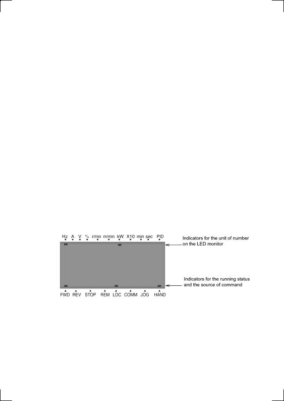
Items Displayed on LED Indicators
Type |
Item |
Description (information, condition, status) |
|
|
|
|
|
|
Hz |
Output frequency, frequency command |
|
|
|
|
|
|
A |
Output current |
|
|
|
|
|
|
V |
Output voltage |
|
|
|
|
|
|
% |
Calculated torque, load factor, speed |
|
|
|
|
|
|
r/min |
Motor speed, set motor speed, load shaft speed, set load shaft speed |
|
Unit of Number |
|
|
|
m/min |
Line speed, set line speed (Not applicable to FRENIC-Eco) |
||
Displayed on |
|||
|
|
||
LED Monitor |
kW |
Input power, motor output |
|
|
|||
|
|
|
|
|
X10 |
Data greater than 99,999 |
|
|
|
|
|
|
min |
Constant feeding rate time, constant feeding rate time setting (Not applicable |
|
|
|
to FRENIC-Eco) |
|
|
|
|
|
|
sec |
Timer |
|
|
|
|
|
|
PID |
PID process value |
|
|
|
|
|
|
FWD |
Running (forward rotation) |
|
Operating |
|
|
|
REV |
Running (reverse rotation) |
||
Status |
|||
|
|
||
|
STOP |
No output frequency |
|
|
|
|
|
|
REM |
Remote mode |
|
|
|
|
|
|
LOC |
Local mode |
|
Source of |
|
|
|
COMM |
Communication enabled (RS485 (standard, optional), field bus option) |
||
Operation |
|||
|
|
||
|
JOG |
Jogging mode (Not applicable to FRENIC-Eco) |
|
|
|
|
|
|
HAND |
Keypad effective (lights also in local mode) |
|
|
|
|
3-3

3.2 Overview of Operation Modes
FRENIC-Eco features the following three operation modes:
■ Running Mode: |
This mode allows you to enter run/stop commands in regular operation. You can also |
|
monitor the running status in real time. |
■ Programming Mode: This mode allows you to set function code data and check a variety of information relating to the inverter status and maintenance.
■ Alarm Mode: |
If an alarm condition occurs, the inverter automatically enters the Alarm Mode. In this |
|
mode, you can view the corresponding alarm code* and its related information on the |
LED and LCD Monitors.
* Alarm code: Indicates the cause of the alarm condition that has triggered a protective function. For details, refer to the FRENIC-Eco Instruction Manual (INR-SI47-0882-E), Chapter 8, Section 8.5 "Protection Features."
Figure 3.1 shows the status transition of the inverter between these three operation modes.
Figure 3.1 Status Transition between Operation Modes
3-4

3.3 Running Mode
When the inverter is turned on, it automatically enters Running Mode. In Running Mode, you can: [ 1 ] Run or stop the motor;
[ 2 ] Set the frequency command and others;
[ 3 ] Monitor the running status (e.g., output frequency, output current)
3.3.1Running/stopping the motor
By factory default, pressing the  key starts running the motor in the forward direction and pressing the
  key decelerates the motor to stop. The
  key is disabled. You can run or stop the motor using the keypad only in Running mode and Programming mode.
To run the motor in reverse direction, or to run the motor in reversible mode, change the setting of function code F02.
For details of function code F02, refer to the FRENIC-Eco Instruction Manual (INR-SI47-0882-E), Chapter 5.
Figure 3.2 Rotational Direction of Motor
Note) The rotational direction of IEC-compliant motor is opposite to the one shown here.
■ Display of running status (on LCD monitor)
(1)When function code E45 (LCD Monitor (optional)) is set to "0," the LCD Monitor displays the running status, the rotational direction, and the operation guide.
(The indicators above the LCD Monitor indicate the unit of the number displayed on the LED Monitor; the indicators underneath the LCD Monitor indicate the running status and the source of Run command.)
Figure 3.3 Display of Running Status
The running status and the rotational direction are displayed as shown in Table 3.2.
Table 3.2 Running Status and Rotational Direction
Status/Direction |
Description |
Running status
RUN: The Run command is present, or the inverter is driving the motor.
STOP: The Run command is not present, or the inverter is in stopped state.
FWD: Forward
Rotational direction REV: Reverse
Blank: Stopped
3-5

(2)When function code E45 (LCD Monitor (optional)) is set to "1," the LCD Monitor displays the output frequency, output current, and calculated torque in a bar chart.
(The indicators above the LCD Monitor indicate the unit of the number displayed on the LED Monitor; the indicators underneath the LCD Monitor indicate the running status and the source of Run command.)
The full scale (maximum value) for each parameter is as follows:
Output frequency: |
Maximum frequency |
Output current: |
200% of inverter’s rated current |
Calculated torque: |
200% of rated torque generated by motor |
|
Figure 3.4 Bar Chart |
■ Switching the operation mode between remote and local
The inverter can be operated either in remote mode or in local mode. In remote mode, which applies to normal operation, the inverter is driven under the control of the data settings held in it, whereas in local mode, which applies to maintenance operation, it is separated from the system and is driven manually under the control of the keypad.
Remote mode: |
The sources for setting run and frequency commands is determined by various |
|
setting means switching signals such as function codes, switching of run command |
|
1/2, and link priority function. |
Local mode: |
The sources for setting run and frequency commands is the keypad, regardless of the |
|
settings specified by function codes. The keypad takes precedence over the setting |
|
means specified by the run command 1/2 or the link priority function. |
What follows shows the setting means of run command using the keypad in the local operation mode.
3-6

Table 3.3 Run Commands from the Keypad in the Local Operation Mode
If function code F02 is set |
Setting means of the run command |
|||
to: |
|
|
|
|
|
|
|
|
|
0: Keypad |
You can run/stop the motor using the |
/ |
/ |
key on the keypad. |
1: External signal |
|
|
|
|
|
|
|
|
|
2: Keypad (forward) |
You can run/stop the motor using the |
/ |
key on the keypad. |
|
|
You can run the motor in forward direction only. (The |
key has been disabled.) |
||
|
|
|
|
|
3: Keypad (reverse) |
You can run/stop the motor using the |
/ |
key on the keypad. |
|
|
You can run the motor in reverse direction only. (The |
key has been disabled.) |
||
|
|
|
|
|
The source for setting run and frequency commands can be switched between Remote and Local modes by the  key on the keypad. (This key is a toggle switch: Each time you press it for more than 1 second, the mode switches from Romote to Local or vice versa.)
The mode can be switched also by an external digital input signal. To enable the switching you need to assign (LOC) to one of the digital input terminals, which means that the commands from the keypad are given precedence (one of function codes E01 to E05, E98, or E99 must be set to "35"). By factory default, (LOC) is assigned to [X5].
You can confirm the current mode on the indicators (REM: Remote mode; LOC: Local mode).
When the mode is switched from Remote to Local, the frequency settings in the Remote mode are automatically inherited. Further, if the inverter is in Running mode at the time of the switching from Remote to Local, the Run command is automatically turned ON so that all the necessary data settings will be carried over. If, however, there is a discrepancy between the settings on the keypad and those on the inverter itself (e.g., switching from reverse rotation in the Remote mode to forward rotation in the Local mode using the keypad that is for forward rotation only), the inverter automatically stops.
The paths of transition between Remote and Local modes depend on the current mode and the value (ON/OFF) of (LOC), the signal giving precedence to the commands from the keypad, as shown in the state transition diagram (Figure 3.5) given below.
For further details on how to set operation commands and frequencies in Remote and Local modes, refer to the FRENIC-Eco User’s Manual (MEH456), Chapter 4 "BLOCK DIAGRAMS FOR CONTROL LOGIC" (especially Section 4.3 “Drive Command Generator” block diagram).
Figure 3.5 Transition between Remote and Local Modes
3-7
Loading...