


 Loading...
Instruction Manual
MICROJET RECORDER E
TYPE: PHE–2
INP-TN2PHEVb-E

PREFACE
Congratulations on your purchase of Fuji Microjet Recorder (Type: PHE)
•Read this instruction manual carefully to ensure correct installation, operation and preparation. Incorrect handling may lead to accidnt or injury.
•Specifications of this unit is subject to change without prior notice for improvement.
•Modification of this unit without permission is strictly prohibited.
Fuji will not bear any responsibility for a trouble caused by such a modification.
•This instruction manual should be kept by the person who is actually using the unit.
•After reading the manual, be sure to keep it at a place easy to access.
•This instruction manual should be delivered to the end user without fail.
Manufacturer |
: Fuji Electric Instrumentation Co., Ltd. |
Type |
: Shown on nameplate of Microjet recorder |
Date of manufacture |
: Shown on nameplate of Microjet recorder |
Product nationality |
: Japan |
Request
•It is prohibited to transfer part or all of the manual without Fuji's permission.
•Description in this manual will be changed without prior notice.
Fuji Electric Systems Co., Ltd. 1999
Issued in November, 1999 Rev. 1st edition April, 2000 Rev. 2nd edition April, 2005
INP-TN2PHEV-E |
- i - |

CAUTION ON SAFETY
First of all, read this “Caution on safety” before using the unit.
•The cautionary descriptions listed here contain important information about safety, so they should always be observed. Those safety precautions are ranked 2 levels, DANGER and CAUTION.
DANGER |
Wrong handling may cause a dangerous situation, in which |
there is a risk of death or heavy injury. |
Wrong handling may invite a dangerous situation, in which
CAUTION there is a possibility of medium level trouble or slight injury or only physical damage is predictable.
PROHIBITION Items which must not be done are noted.
Caution on Installation
• This unit is not an explosion-proof type. Do not use it in a place DANGER with explosive gases to prevent explosion, fire or other serious
accident.
• For installation, select a place observing the operating condi-
CAUTION tions noted in the instruction manual. Installation at an unsuited place may cause fall, trouble or malfunction.
•The unit must be installed correctly as shown in the instruction manual. Incorrect installation may cause fall, trouble or malfunction.
•During installation work, keep the inside of the unit free from entry of cable chips or other foreign objects as it may cause fire, trouble or malfunction.
This unit is a component device used for instrumentation. It is CAUTION mounted on a panel or in a rack.
•The unit conforms to IEC1010-1 (1990) Safety Standards, and is designed for protection class I, overvoltage Category II and pollution degree 2, except the alarm output terminal (overvoltage category I).
•EMC conforms to EN50081-1 (1992) and EN50082-1 (1992), (both used for housing areas), except that the noise level of the power terminal is rated for Class A (used for commercial and industrial areas).
•Input signals and communication interface should be of SELV (safety separated from hazardous voltage).
- ii - |
INP-TN2PHEV-E |

Caution of Wiring
DANGER |
• Wiring work must be performed as specified. If the unit is not |
|
earthed, it would result in electric shocks or malfunction. |
|
|
|
• Be sure to connect power source that matches the rating. Con- |
|
|
nection of incorrect rating of power source may lead to fire. |
|
|
• Before starting wiring work, be sure to turn OFF the main power |
|
|
to prevent electric shocks. |
|
|
• Wiring materials to be used must meet the rating. Use of mate- |
|
|
rials which do not withstand the rating may cause a fire accident. |
|
|
|
|
|
|
|
Caution on Maintenance |
|
|
|
|
|
DANGER |
• When disposing of the recording head, put it in a vinyl bag |
|
and seal it to prevent the diffusion of ink. It should be handled |
|
|
|
as an imcombustible object when disposing of it. |
|
|
• Ink is harmful to human body. Observe the following emer- |
|
|
gency treatments. |
|
|
. When ink gets in eyes, wash out for at least 5 minutes |
|
|
immediately with much clean water, and ask your doctor |
|
|
for treatment at once. |
|
|
. When ink gets on skin, wash out and clean skins with |
|
|
soap and water. |
|
|
. When ink is breathed in, move to a clean place immedi- |
|
|
ately. If necessary, ask your doctor for treatment at once. |
|
|
• Do not touch the connector at the rear of the carriage mount- |
|
|
ing the recording head to avoid the risk of electric shocks. |
|
|
|
|
|
|
|
Caution on Use |
|
|
|
|
|
DANGER |
• If the fault or anomaly of the device may cause serious acci- |
|
dent or troubles to other devices, externally install appropri- |
|
|
|
ate protective circuit to avoid accidents. |
|
|
• The instrument has no power switch nor fuse. Install them if |
|
|
necessary. |
|
|
• When fuse is blown out, check and remove the cause of it, |
|
|
and replace it with new one specified in the instruction manual. |
|
|
Do not use any other fuse or short it, as it may cause electric |
|
|
shocks or fire. |
|
|
|
|
INP-TN2PHEV-E |
- iii - |

CONTENTS
PREFACE .................................................................................................................................. |
i |
||
CAUTION ON SAFETY .............................................................................................................. |
ii |
||
1. |
INTRODUCTION ............................................................................................................. |
1-1 |
|
|
1.1 |
Microjet recorder ...................................................................................................................... |
1-1 |
|
1.2 |
Product check ........................................................................................................................... |
1-1 |
|
1.3 |
Check on type and specification ............................................................................................... |
1-2 |
2. |
NAMES AND FUNCTIONS OF PARTS ........................................................................... |
2-1 |
|
3. |
MOUNTING METHOD ..................................................................................................... |
3-1 |
|
|
3.1 |
Mounting location .................................................................................................................... |
3-1 |
|
3.2 |
External dimensions and panel cut out dimensions ................................................................. |
3-1 |
|
3.3 |
Method of mounting onto panel ............................................................................................... |
3-2 |
4. |
WIRING ........................................................................................................................... |
4-1 |
|
|
4.1 |
Before wiring ........................................................................................................................... |
4-1 |
|
4.2 |
Caution on power source wiring .............................................................................................. |
4-1 |
|
4.3 |
Connection to terminals ........................................................................................................... |
4-2 |
5. |
SET-UP ............................................................................................................................ |
5-1 |
|
|
5.1 |
Loading chart paper .................................................................................................................. |
5-1 |
|
5.2 |
Recording head installation (replacement) ............................................................................... |
5-5 |
6. |
OPERATION AND ACTIONS .......................................................................................... |
6-1 |
|
|
6.1 |
Before running the equipment: ................................................................................................. |
6-1 |
|
6.2 |
Turning on power and status .................................................................................................... |
6-2 |
|
6.3 |
Printing the test pattern ............................................................................................................ |
6-2 |
|
6.4 |
Operation in normal mode ....................................................................................................... |
6-3 |
|
6.5 |
Displays and print-outs on detection (cancellation) of alarms ................................................. |
6-4 |
|
6.6 |
Displays and print-outs on occurrent of burnt-out ................................................................... |
6-4 |
|
6.7 |
Indication of over-range, under-range display and abnormal input display ............................. |
6-5 |
|
6.8 |
Display of fault in recording head carriage .............................................................................. |
6-5 |
|
6.9 |
Display of skipped parameter ................................................................................................... |
6-5 |
 Chapter 3,4 and chapter 8 should be observed for installation and mainte- CAUTION nance of the unit. So, it must be performed by qualified engineers.
- iv - |
INP-TN2PHEV-E |

7. SETTING AND CHECKING PARAMETERS ................................................................... |
7-1 |
||
|
7.1 |
Setting and Checking ............................................................................................................... |
7-1 |
|
7.2 |
Outline of procedure for setting parameters ............................................................................. |
7-2 |
|
7.3 |
Key lock setting/release ............................................................................................................ |
7-3 |
|
7.4 |
Setting the Chart Speed (main chart speed) ............................................................................. |
7-4 |
|
7.5 |
How to list ................................................................................................................................ |
7-5 |
|
7.6 |
How to print the scale (manually) ............................................................................................ |
7-6 |
|
7.7 |
How to set ON/OFF of periodic print-out ................................................................................ |
7-7 |
|
7.8 |
How to set ON/OFF of scale print-out ..................................................................................... |
7-8 |
|
7.9 |
How to set the input filter ....................................................................................................... |
7-10 |
|
7.10 |
How to set the alarm ............................................................................................................... |
7-11 |
|
7.11 |
Selecting whether to start recording when turning on ........................................................... |
7-13 |
|
7.12 |
Setting of date and time .......................................................................................................... |
7-14 |
8. |
MAINTENANCE - INSPECTION ..................................................................................... |
8-1 |
|
|
8.1 |
Maintenance/inspection items .................................................................................................. |
8-1 |
|
8.2 |
Battery replacement procedure ................................................................................................. |
8-2 |
9. |
ADJUSTMENT MODE ..................................................................................................... |
9-1 |
|
|
9.1 |
How to adjust the printing and recording (adjust the backlash) ............................................... |
9-1 |
|
9.2 |
How to position the analog trend recording (position the head zero/span) .............................. |
9-2 |
|
9.3 |
How to set the PV shift ............................................................................................................ |
9-3 |
|
9.4 |
How to set the sub chart speed ................................................................................................. |
9-5 |
|
9.5 |
How to set the skip ................................................................................................................... |
9-6 |
|
9.6 |
Head selection .......................................................................................................................... |
9-7 |
|
9.7 |
How to calibrate measured value (ADJUST) ........................................................................... |
9-8 |
10. TROUBLESHOOTING ................................................................................................. |
10-1 |
||
11. EXAMPLES OF RECORDING AND PRINTING .......................................................... |
11-1 |
||
|
11.1 |
Periodic print-out and scale print-out ..................................................................................... |
11-1 |
|
11.2 |
Digital print-out (Instantaneous values) ................................................................................. |
11-2 |
|
11.3 |
Parameter listing ..................................................................................................................... |
11-2 |
|
11.4 |
Test pattern ............................................................................................................................. |
11-3 |
|
11.5 |
Scale print-outs (manual print-outs) ....................................................................................... |
11-3 |
|
11.6 |
Alarm print-outs ..................................................................................................................... |
11-4 |
|
11.7 |
Burn-out print-out .................................................................................................................. |
11-4 |
|
11.8 |
Record start mark ................................................................................................................... |
11-4 |
|
11.9 |
Chart speed change mark ....................................................................................................... |
11-4 |
12. SPECIFICATION .......................................................................................................... |
12-1 |
||
APPENDIX 1. MOUNTING OF PHE OPTIONAL UNITS ...................................................... |
A-1 |
||
APPENDIX 2. SYSTEM PARAMETER SETTING ................................................................. |
B-1 |
||
APPENDIX 3. CHANGE OF HARDWARE ........................................................................... |
C-1 |
||
INP-TN2PHEV-E |
- v - |
1. INTRODUCTION
We thank you for purchasing Microjet Recorder PHE.
The instruction manual describes installation, operation, maintenance, etc. of Microjet Recorder. Read
it carefully before use.
1.1Microjet recorder
This recorder (100mm wide) is used to record up to 6 points of input signals from a thermocouple, resistance bulb and DC voltage.
Analog trend data and digital print data are color recorded clearly and quickly.
Analog trend data can be recorded continuously or intermittently (see Item 1.3 “Check on type and specification”).
Besides recording measured values, chart paper feed speed, measurement range, etc. can be printed as standard functions.
1.2Product check
Upon receiving the unit, check the appearance and accessories to make sure that they are not damages. Also, check that the accessories are supplied correctly.
Check on accessories
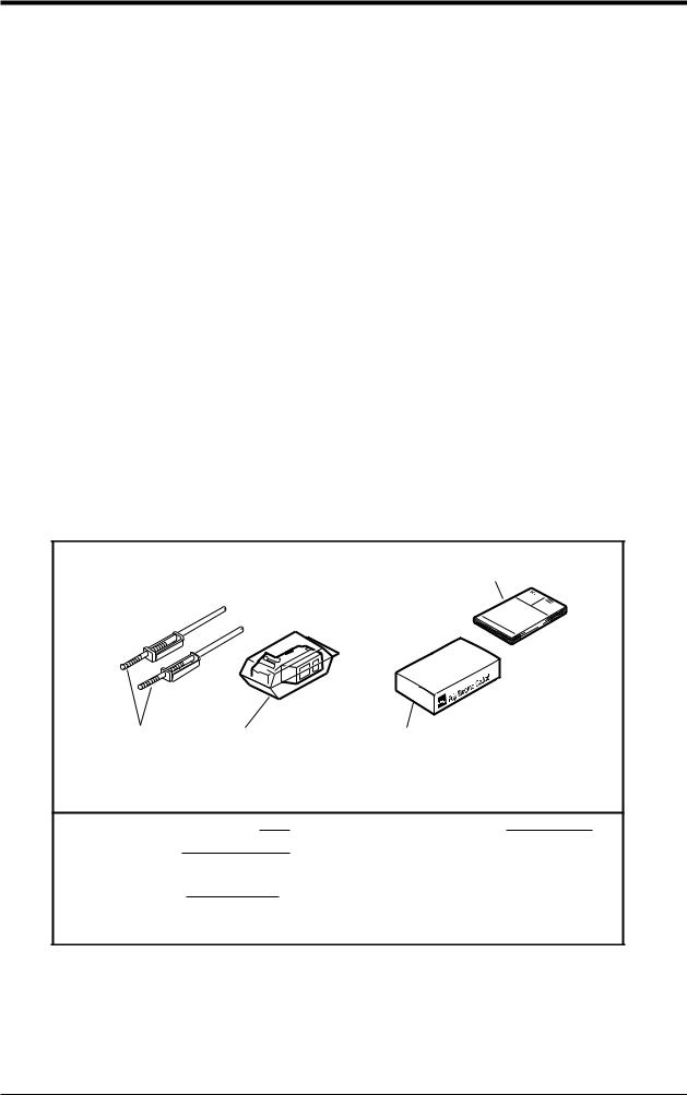
The unit comes with the accessories shown in Fig. 1-1. Please check that they are all there.
Instruction Manual
Panel-mounting |
Recording head, with Recording paper |
attachments |
cloth for absorbing ink |
(Keep the ink blotting cloth so as not to be lost.)
Panel-mounting attachments |
2 |
Instruction Manual |
1 |
Recording head |
1 |
|
|
with cloth for absorbing ink |
|
|
|
Recording paper |
1 pack |
|
|
(The standard recording paper No. is |
|
|
|
PEX00DL1-5000B) |
|
|
|
Fig. 1-1 Accessories
INP-TN2PHEV-E |
1 - 1 |

1.3Check on type and specification
|
|
|
|
10 11 12 13 |
|
||||||||||||
|
|
|
|
0 |
0 |
|
2 |
|
|
|
V |
V |
|
E |
V |
|
|
|
|
|
|
|
|
|
|
||||||||||
|
|
|
|
|
|
|
|
|
|
|
|
|
|
|
|
|
|
|
|
|
|
|
|
|
|
|
|
|
|
|
|
|
|
Recording points |
Description |
|
|
|
|
|
|
|
|
|
|
|
|
|
|
|
|
||
|
|
|
|
|
|
|
|
|
|
|
|
|
|
|
1 continuous recording |
||
|
|
|
|
|
|
|
|
|
|
|
|
|
|
|
|
2 continuous recording |
|
|
|
|
9 |
|
|
|
|
|
|
|
|
|
|
|
|
6 intermittent recording |
|
|
|
|
|
|
|
|
|
|
|
|
|
|
|
|
|
|
|
|
|
|
|
|
|
|
|
|
|
|
|
|
|
|
|
Power supply · Temperature Unit |
|
|
|
|
|
|
|
|
|
|
|
|
|
|
|
|
|
100 to 120VAC 50/60Hz °C |
|
|
|
|
|
|
|
|
|
|
|
|
|
|
|
|
|
200 to 240VAC 50/60Hz °C |
|
|
|
|
|
|
|
3 |
|
|
|
|
|
|
|
|
|
100 to 120VAC 50/60Hz °F |
|
|
|
|
|
|
|
4 |
|
|
|
|
|
|
|
|
|
200 to 240VAC 50/60Hz °F |
|
|
|
|
|
|
|
|
|
|
|
|
|
|
|
|
|
Alarm output/external control input (1 point) |
|
|
|
|
|
|
|
|
|
|
|
|
|
|
|
|
|
Without |
|
|
|
|
|
|
|
|
|
|
|
|
|
|
|
|
|
2 points alarm output (1 continuous only) |
|
|
|
|
|
|
|
|
|
|
|
|
|
|
|
|
|
4 points alarm output (2 continuous only) |
|
|
|
|
|
|
|
|
|
|
|
|
|
|
|
|
|
6 points alarm output (6-intermittent only) |
|
|
|
|
|
|
|
|
|
|
|
|
|
|
A |
|
|
2 points alarm output/External control |
|
|
|
|
|
|
|
|
|
|
|
|
|
|
|
|
|
|
(1 continuous only) |
|
|
|
|
|
|
|
|
|
|
|
|
|
B |
|
|
4 points alarm output/External control |
|
|
|
|
|
|
|
|
|
|
|
|
|
|
|
|
|
|
(2 continuous only) |
|
|
|
|
|
|
|
|
|
|
|
|
|
C |
|
|
6 points alarm output/External control |
|
|
|
|
|
|
|
|
|
|
|
|
|
|
|
|
|
|
(6-intermittent only) |
|
|
|
|
|
|
|
|
|
|
|
|
|
|
|
|
|
|
|
|
|
|
|
|
|
|
Input |
: Universal (Programmable) |
|
|||||||
|
|
|
|
|
|
|
|
Range |
: Field settable (Programmable) |
|
|||||||
Note) 1. Initial set before delivery is ;
• Thermocouple K type 0 to 1200°C
2.Shunt resistor (10Ω±0.1%) should be ordered separately for current input.
Shunt Resistor : Ordering code PHZT1101
Note) Items to specify when ordering except model : PHE □00
1.Code symbols (according to above table)
2.Recording range (scale) and unit in case of DC voltage and DC current input.
For 2 continuous type, recording range and unit should be specified for each channel 1 and channel 2.
3.Recording range should be specified with 3 or more effective figures.
exp. 0 to 100, 0.0 to 10.0, 0.00 to 1.00
Note) Change of kinds of input signal
When changing the kinds of input signal, some adjustments may become necessary. For adjustments, refer to Appendix, page B-6.
1 - 2 |
INP-TN2PHEV-E |

2. NAMES AND FUNCTIONS OF PARTS
Recording head
Paper feed unit drawout lever
Display unit Function key board
(1)Display unit
Time, measurement data, set values and comments are displayed.

 Under recording Lamp (LED) ON

 Measured value and set value are displayed. Channel is displayed.
(2)Recording head
Used for analog trend recording and digital printing. (Recording head is not mounted in the recorder prior delivery. It should be mounted referring to Item 5.2)
(3)Paper feed unit drawout lever
When setting (replacing) chart papaer, press down the drawout lever and the paper feed unit will be drawn out. If it is not drawn out automatically, pull out the paper feed unit by hand while pressing down the lever.
INP-TN2PHEV-E |
2 - 1 |

(4)Function key board
Used for setting or confirming parameters and for operating the recorder.
Reset switch
|
|
|
Normal mode |
DSP |
FEED |
REC |
|
|
|
|
|
|
|
|
|
|
|
|
Setting mode |
SEL |
|
ENT |
|
Normal mode |
: |
Measured value or the states of alarm of each channel is displayed. This |
|||||
|
|
mode is started at power ON. |
|
|
|
||
Setting mode |
: |
This mode is used for setting chart speed or alarm. |
|||||
|
Name of key |
Function |
|||
|
REC |
Recording start/stop function key. Recording is started at the first press of the key |
|||
|
(record) |
and stops at the second press. |
|||
|
|
|
|
|
|
mode |
FEED |
Chart paper fast feed key |
|||
(feed) |
Feed speed becomes fast by pressing the key for more than 3 seconds. |
||||
|
|
|
|
||
|
|
|
|
||
Normal |
DSP |
1. Used for changing display data . The following 2 functions are selected at |
|||
(display) |
each press of the key. |
||||
|
|
|
(1) Data of all channels are displayed in order, except for the skip channel. |
||
|
|
|
|
||
|
|
|
|
(2) Display only of the data of specific channels. |
|
|
|
|
|
2. Used when shifting from normal mode to setting mode (press the key for more |
|
|
|
|
|
than 3 seconds) |
|
|
|
|
|
|
|
|
ENT |
Used to register set data and to start or stop list printing. |
|||
|
(entry) |
|
|||
|
|
|
|
|
|
mode |
|
|
|
Used to change set data. Chart paper fast feed is effected during list printing. |
|
|
|
|
|||
|
|
|
|
||
|
(up) |
|
|||
Setting |
|
|
|
|
|
SEL |
1. Used to read parameters in order in setting mode. This key can not be used |
||||
during list printing. |
|||||
|
|||||
|
(select) |
||||
|
|
||||
|
|
|
|
2. Used when shifting from setting mode to normal mode (press the key for more |
|
|
|
|
|
than 3 seconds) |
|
|
|
|
|
|
|
|
Reset switch |
Used to reset the recorder (The operation is the same as that at power ON/OFF.) |
|||
|
|
|
|
|
|
2 - 2 |
INP-TN2PHEV-E |
3. MOUNTING METHOD
This unit is designed to be panel mounted.
3.1Mounting location
Select the following location for mounting the unit.
(1)A place that is not subject to vibration or shock.
(2)A place where there is no corrosive gas.
(3)A place that is subject to little temperature variation and is close to normal temperature (23°C)
(4)A place that is not struck directly by strong radiant heat.
(5)As humidity affects the ink and recording paper, select a place that is in the range 45 to 80% RH.
(6)Mount the unit horizontally, with no tilt to the left or right.
(The forward tilt should be 0° but the unit may be inclined 0 to 30° rearwards.)
α
α 60 to 90°
3.2External dimensions and panel cut out dimensions (unit: mm)
Mounting attachment |
2 t 30 |
Alarm external control terminal (option) |
t |
|
|
|
|
|
|
|
Panel |
Number of |
|
+ 1.5 |
||
|
Input terminal (for 6 dot) |
|
|
|
units |
|
L 0 (mm) |
|||||
|
|
|
|
|
|
|
|
|
2 |
|
|
282 |
|
|
|
|
|
|
|
|
|
3 |
|
|
426 |
|
|
|
|
161 |
136.5 |
|
144 |
|
4 |
|
|
570 |
|
|
|
|
|
|
5 |
|
|
714 |
|||
|
|
|
|
|
|
|
|
|
|
|
||
|
|
|
|
|
|
|
|
|
6 |
|
|
858 |
|
|
|
|
|
|
|
|
|
7 |
|
|
1002 |
|
|
|
|
|
22 |
175 |
|
|
8 |
|
|
1146 |
|
|
|
|
|
|
|
9 |
|
|
1290 |
||
|
|
|
|
|
|
|
|
|
|
|
||
|
136.4 |
|
|
|
197 |
19 |
144 |
10 |
|
|
1434 |
|
|
|
|
|
|
|
|
|
|
|
|
||
Power supply terminal |
|
|
|
|
|
|
|
n |
(144×n 6 |
|||
|
|
Input terminal (for 1, 2 continuous) |
|
|
|
|
|
|
||||
|
|
|
|
|
|
Mass |
: |
Continuous type |
Approx. 1.3kg |
|
||
PANEL CUTOUT |
|
|
|
|
|
|
|
(without alarm terminal) |
||||
|
|
|
|
|
|
|
Approx. 1.5kg |
|
|
|||
|
|
|
|
|
|
|
|
|
|
|
||
For single unit mounting |
For left/right tight fit mounting |
|
(with |
alarm terminal) |
||||||||
|
+1.5 |
|
|
|
+1.5 |
|
|
Intermittent type |
Approx. 1.5kg |
|
||
|
137 0 |
|
|
|
L 0 |
|
|
|
||||
|
|
|
|
|
|
|
|
|
(without alarm terminal) |
|||
+1.5 |
0 |
+1.5 |
0 |
|
|
|
|
|
Approx. 1.7kg |
|
|
|
|
|
in |
|
|
|
|
|
|
||||
137 |
137 |
|
|
|
|
(with |
alarm terminal) |
|||||
|
|
|
|
|
|
|
|
|
||||
|
|
|
|
|
|
175 |
|
Power consumption : |
|
|
|
|
|
|
|
|
|
|
|
|
|
|
|
||
|
|
|
|
|
|
|
|
Approx. 13VA (100V AC, without option) |
||||
|
|
|
|
|
|
|
|
Approx. 15VA (100V AC, with all options) |
||||
INP-TN2PHEV-E |
3 - 1 |

3.3Method of mounting onto panel
Panel
Screw
•Using the supplied mounting fixture, tighten the upper and lower screws until the panel is fixed.
•The panel to be used should be more than 2mm thick.
3 - 2 |
INP-TN2PHEV-E |

4. WIRING
4.1Before wiring
For thermocouple input, be sure to use a compensated lead wire.
Input signal cables should be wired separately as far as possible (30cm or more) from power lines and high-voltage lines to minimize the effect of inductive noise. Shielded cables should preferably be used. In this case, the shield braids should be earthed at one point.
Notes
(1) At the completion of wiring of the input terminals, be sure to close the rear cover to ensure the compensation of reference contact when thermocouple input is used.
(2) For connection of lead wires to terminals, use of sleeveinsulated clamping terminals (for M4 screws) is recommended.
4.2Caution on power source wiring
This recorder has no power fuse. Mount a power fuse outside the recorder as necessary. Recommend fuse rating : AC250V, 1A
When connecting power cable and earth cable to terminals, be sure to use crimp style terminals with insulated sleeves (M4 screw).
For power cable connection, be sure to use 600V vinyl insulated cable or equivalent.
Before making a wiring work, be sure to turn OFF the main power to prevent
the risk of electric shocks. After wiring, be sure to close the cover. DANGER Wiring materials to be used must meet the rating. Use of materials which do
not withstand the rating may cause a fire accident.
Wring work must be performed as specified. If the unit is not earthed, it would result in electric shocks or malfunction.
The recorder is not provided with a power fuse.
Use an external power fuse.
CAUTION Rating : T1A, 250V AC or equivalent protection.
INP-TN2PHEV-E |
4 - 1 |

4.3 Connection to terminals
1, 2 continuous recording |
|
6 dot recording_ |
||||||||||||||||||||
|
|
|
For 6 dot (channel 1 to 6) |
|||||||||||||||||||
|
|
|
|
|
|
|
|
|
|
|
|
|
|
|
|
|
|
|
|
|
|
|
|
|
|
|
|
|
|
|
|
|
|
|
|
|
|
|
|
|
|
|
|
|
|
|
|
|
|
|
|
|
|
|
|
|
|
|
|
|
|
|
|
|
|
|
|
|
|
|
|
|
|
|
|
|
|
|
|
|
|
|
|
|
|
|
|
|
|
|
|
|
|
|
|
|
|
|
|
|
|
|
|
|
|
|
|
|
|
|
|
|
|
|
|
|
|
|
|
|
|
|
|
|
|
|
|
|
|
|
|
|
|
|
|
|
|
|
|
|
|
|
|
|
|
|
|
|
|
|
|
|
|
|
|
|
|
|
|
|
|
|
|
|
|
|
|
|
|
|
|
|
|
|
|
|
|
|
|
|
|
|
|
|
For 1, 2 continuous (channel 1) |
|
|
|
For 2 continuous (channel 2)
|
Input terminal |
Connect signal cable for each channel. |
Alarm/external control unit |
Connect the alarm signal output and external control signal in- |
|
|
(option) |
put (for alarms 1 to 6, external control). |
Power terminal
Earth terminal
Connect power cable to L N terminal. Power source to be connected should be free from noise .
(Code symbol : 100 to 120V AC or 200 to 240 V AC, 50/60 Hz)
Connect to PE terminal (Class-3, less than 10 Ω ).
Alarm output terminals ( 11 to 16 , 21 to 26 ) are of overvoltage category I. Other
 terminals (input signals, communication interface) are for SELV signals (safety sepa- CAUTION rated from hazardous voltage).
4 - 2 |
INP-TN2PHEV-E |

(1)Connection of input terminals
Input terminal No. is determined for each channel.
Connect input terminals according to the relation between the number of points of input signal and channel shown in Code Symbols (see Item 1.3).
|
[For 1, 2 continuous] |
|
|
[For 6 dot] |
|
|
|
|
Resistance bulb (RTD) |
|
RCJ module |
|
RCJ module |
|
|
|
|
Thermocouple (Tc)
Terminal No.
DC voltage (V)
21 |
|
22 |
|
23 |
11 |
|
12 |
|
13 |
|
|
|
|
|
|
|
|
|
|
|
2 continuous |
|
|
1 continuous |
|
||||
Terminal No.
|
|
|
|
|
Input 1 |
|
|
||||
|
|
|
|
|
|
|
|
|
|
|
Input 2 |
|
|
||||
|
|
|
|
|
|
|
|
|
|
|
Input 3 |
|
|
||||
|
|
|
|
|
|
|
|
|
|
|
Input 4 |
|
|
||||
|
|
|
|
|
|
|
|
|
|
|
Input 5 |
|
|
||||
|
|
|
|
|
|
|
|
|
|
|
Input 6 |
|
|
||||
|
|
|
|
|
|
|
|
|
|
|
NC |
|
|
||||
|
|
|
|
|
|
Before starting wiring work, be sure to turn OFF the main power to prevent
DANGER |
the risk of electric shocks. |
||
|
|
||
|
|
|
|
Example |
Input terminal wiring |
<1, 2 continuous> |
|
|
|
|
|
DC voltage input Thermocouple input |
Resistance bulb input |
|
|
|
|
|
|
b B |
A |
DC current input
|
|
DC votlage input |
|
|
RCJ module Compensating leads
Black (b)
Thermocouple
Shunt resistance
White (B) |
|
Red (A) |
DC current input |
|
Example : 10Ω ±0.1% shunt
resistance is used for Resistance bulb 4 to 20mA and 10 to
50mA input.
Note : Avoid using thermocouple |
In this case, ±500mV |
|
input with wiring parallel |
||
input range is available. |
||
to other instruments. |
||
|
INP-TN2PHEV-E |
4 - 3 |

Example |
Input terminal wiring |
<6 dot> |
|
|
|
DC voltage input Thermocouple input |
Resistance bulb input |
|
|
|
|
|
|
|
|
A B |
b |
DC current input
|
|
|
|
DC votlage input
Compensating leads
Red (A)
Thermocouple
Shunt resistance
White (B) |
|
|
Black (b) |
DC current input |
|
Example : 10Ω ±0.1% shunt
resistance is used for Resistance bulb 4 to 20mA and 10 to
50mA input.
Note : Avoid using thermocouple |
Note : The line between channels |
input with wiring parallel |
is not insulated only at |
to other instruments. |
input from resistance bulb. |
|
Be sure to use an insulated |
|
type resistance bulb input unit. |
4 - 4 |
INP-TN2PHEV-E |

(2)Alarm output/remote control unit (option)
About alarm outputs :
Alarm setting (2 points) is provided for each input channel. Alarm output is option and selected from among 2 points, 4 points and 6 points.
When an alarm is generated, the relevant terminals are shorted.
1a contact output : Relay contact capacity 240V AC/3A, 30V DC/3A (resistive load)
Alarm 1 to 6 corresponds to DO output No. 1 to 6 on the alarm setting panel. For details, refer to the alarm setting method under Item 7.10.
1121 Alarm 1
1222 Alarm 2
1323 Alarm 3
1424 Alarm 4
1525 Alarm 5
1626 Alarm 6
Note : If lamps are used on the outside, insert a resistor to prevent surge current.
Also, if relays or solenoids are used, insert elements for contact protection (diodes, surge killers, etc.).
External control unit
This unit has a function “Chart speed selection” using contact signals from the outside of the recorder.
Wiring
17 |
27 (DI) Chart speed selection |
Sub-chart speed at short, |
|
|
and main chart speed at open |
Note 1) The external control unit is not insulated and should be used with a relay connected to the outside.
External contact capacity : 12V DC/0.05A, 1a contact
Note 2) Recording start/stop operation is selected by setting sub-chart speed to 0 mm/h. For details, refer to the sub-chart speed under Item 9.4.
Before starting wiring work, be sure to turn OFF the main power to prevent
the risk of electric shocks.
DANGER
(3)Caution on connection of input signal through barrier
A)Thermocouple input and resistance bulb input.
Perform "Calibration of measured value" with the input connected to the barrier recorder because the barrier internal resistance is added and causes an error in the measured value.
For the calibration method, refer to Item 9.7.
B)When using Fuji Zener Barrier (PWZ), a power source 100V AC line (100 to 120V AC) should be used to ensure safe operation of the unit.
INP-TN2PHEV-E |
4 - 5 |

5. SET-UP
5.1Loading chart paper
Step 1
Prepare chart paper.
Loosen both ends of the chart paper thoroughly to prevent sheets from being fed together.
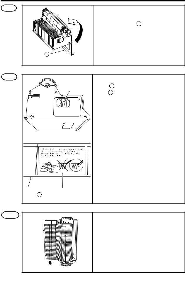
Step 2
Open the front door and press down the paper feed unit drawout lever.
The paper feed unit will be drawn out.
Step 3 |
Chart paper retainer |
|
Hold the chart paper retainer B and open it back- |
|
|||
|
|
|
ward. |
|
|
|
Also, hold and open the chart paper retainer A . |
Chart paper retainer
INP-TN2PHEV-E |
5 - 1 |

Step 4 |
Chart paper |
|
Chart paper retainter A
Chart paper retainter B
Paper feed unit
Set chart paper in the chart paper retainer B as illustrated.
Step 5
Align the perforations of the chart paper with the pins.
Pin
Step 6
Close the chart paper retainer B . (The chart paper is set vertically).
Chart paper retainter B
Step 7
Turn clockwise the gear of the roller unit with hand and check that the chart paper shifts forward.
Gear
5 - 2 |
INP-TN2PHEV-E |
Step 8
Chart paper retainter A
Transfer the chart paper that has been forwarded into the storage of the paper feed unit. Then close the chart paper retainer A .
Step 9
Check the chart paper through this hole.
Chart paper |
Caution in setting |
retainter B |
a chart paper |
As shown by the caution display on the chart paper retainer B , if paper is caught in the chart paper retainer B , paper jam may result.
As shown by the figure at left, check through the holes on the left and the right side of the paper feed unit that the chart paper is not caught in the retainer.
Step 10
Side provided with long holes
The chart paper is provided with long holes and short holes. Gather the chart paper in the storage to the side provided with short holes as illustrated on the left.
Gather the |
Side provided |
|
chart paper |
||
with short holes |
INP-TN2PHEV-E |
5 - 3 |
Step 11
Step 12
Mount the paper feed unit in the recorder. At this time, check that it is properly locked in position.
Press the FEED key and check that the chart paper is fed out smoothly.
(Feed out about 2 folds of paper.)
<If the paper is not fed out smoothly, go through the procedure from Step 2 again.>
Note 1 Selection of chart paper
The chart paper greatly affects the quality of the printed recording and it is also related to problems such as paper jamming, etc.
Please be sure to use the pure-quality chart paper specified us.
Chart paper type: PEX00DL1-5000B (50 equal divisions, no time lines).
Note 2 Use of the recorder after it has been left unused for a long time
If the recorder is left unused for a long time with chart paper still in the main unit, the paper 'packs down' and if the recorder is used straightway there can be problems of paper jamming, etc.
If you use the equipment after it has been left unused for a long time, first press the FEED key to feed out 2 to 3 folds of the paper.
Reference 1 Chart paper length
The chart paper is approximately 15m long. This permits about 31 days continuous print-out at a chart speed of 20mm/h.
Reference 2 Chart paper end mark
The remainder of chart paper is indicated by numerals on the right of paper (unit : 10cm). When it becomes small, a red band will appear on the right to indicate that the chart paper needs to be replaced with new one.
(Note) The recorder is not provided with a chart paper end sensor. When chart paper is used out, stop recording or replace the chart paper with new one.
5 - 4 |
INP-TN2PHEV-E |

5.2Recording head installation (replacement)
The recording head is a combination of a head and ink.
When ink is used out or trouble arises with the head, it can easily be replaced.
Use the recording head carefully observing the “Caution” noted in the later paragraph.
Step 1
Step 2
Step 3
How to close the cap
Get the recording head ready by taking it out of its aluminium pack.
Tear the tape.
Open the cap by turning it in the direction indicated by the arrow.
(If the head is not going to be used for a long time, close the cap back in its original position.)
The cap is integral with the head unit. Turn it about 180° until it stops against the top of the head.
•Lightly attach the supplied cloth to the nozzle
(ink ejecting side) to such up the ink. For the standard head, check to make sure that 4-color ink, blue, red, yellow and black, are soaked into the cloth (for the 2-color head, 2 colors of ink are soaked).
First press the cloth against the surface for 2 to 3 second; if the 4 colors ooze out, it is OK.
Note) Do not use any cloth other than the supplied one. Also, do not rub the nozzle with the cloth.
Cap
Stopper
•Turn the cap in the direction indicated by the arrow and press it firmly until it is retained by the stopper.
•Ink may leak out if the cap is not properly in place.
INP-TN2PHEV-E |
5 - 5 |

Step 4 |
• Press the REC key. Operate the recorder after it |
|
|
|
has been set in recording stop mode. |
|
• Open the front door and press down the paper |
|
feed unit drawout lever. |
|
The paper feed unit will be drawn out. |
Step 5 Recording head
|
• Hold the recording head horizontally, line it up |
|
with the carriage in the main unit, slide it in |
|
slowly and press it firmly until it does not go in |
|
any further. |
Nozzle cariage |
• Take care not to bang the nozzle surface of the |
|
head. Also, avoid touching the nozzle surface with |
|
your hand. |
|
Do not touch the connector at the rear |
|
CAUTION of the carriage to avoid the risk of mi- |
|
nor electric shocks. |
Step 6
Set the paper feed unit in its original position.
The above completes installation of the recording head.
The recording head is a consumable part. When the built-in ink is used out, replace the head with
new one.
It comes in 2 types, one is for the 1, 2 continuous recording (PHZH2002) and another for the 6 dot recording (PHZH1002). Choose the type of the head according to the recording mode of the recorder.
5 - 6 |
INP-TN2PHEV-E |

Recording head replacement
Draw out the recording head in the manner that is opposite to what is described in Step 5 of the recording head setting procedure, and replace it with a new recording head.
Always carry out the following procedure after replacing a recording head.
(1) Test pattern print-out
Print out a test pattern to check that normal recording is possible. See Section 6.3 for the way of printing out a test pattern.
(2) Adjustment of analog trend recording positions
Referring to Section 9.2, readjust the zero and span on the recording paper.
INP-TN2PHEV-E |
5 - 7 |
Precautions in handling recording heads
Handling recording heads
• Do not knock or shake recording heads as this can cause faults.
DANGER • The inks are not harmful but they are very difficult to remove if they adhere to the skin or to clothes, so handle heads carefully in order to avoid staining. Also, do not disassemble
them.
•If, by accident, it happens that ink gets into your eyes, wash thoroughly with water as an emergency measure and then immediately consult a specialist doctor.
•When the recording head is empty of ink, it should be disposed of as a incombustible object or returned to our office for reuse (recycling).
Note 1 If recording is halted and the recorder is not used for a long time
Carry out the following in order to prevent jamming and drying-up of the ink.
Remove the recording head from the main unit, make absolutely sure the cap is closed properly and store the head in a cool, dark place (average temperature 5 to 30°C).
If the head is left installed in the recorder:
Do not switch off the power to the recorder and do not close the cap.
*Periodically, there is an automatic discharge of ink to prevent drying-up. Leave the recording paper in place in the recorder.
If it is not possible to keep the power switched on, make sure that the cap is closed.
Draw out the paper feed unit using the recording head setting method Step 4 .
Open the indicator and tighten the cap.
Note 2 At the start of use of a recording head
If you are starting to use a new recording head or if the recorder has been left unused for a long time, always wipe the head's nozzle surface lightly with the accessory cloth and check that the ink oozes out properly into the cloth. (See Step 3.)
Also, after normal recording is possible. See Section 6.3 for the way of printing out a test pattern. When the working environment is 15°C or less, perform print-out of "test pattern" after period of several minutes has elapsed since the recording head was mounted. (The recording head has a built-in heater.)
Note 3 Storage of recording heads
When they are delivered, recording heads are in aluminium packs.
If you are not going to use a head straight-away, leave it sealed and store it in a cool, dark place with an average temperature of 5 to 30°C.
5 - 8 |
INP-TN2PHEV-E |
Note 4 Shipping of recording head
•Do not ship the unit recording head after the aluminum pack was opened up. If it is necessary to ship the unit recording head under avoidable circumstances, be sure to close the cap, and ship it as contained in a boxboard in the state where vibration and impack are eased using cushioning materials.
•Always close the cap if you are transporting a head while it is still installed in the recorder main unit.
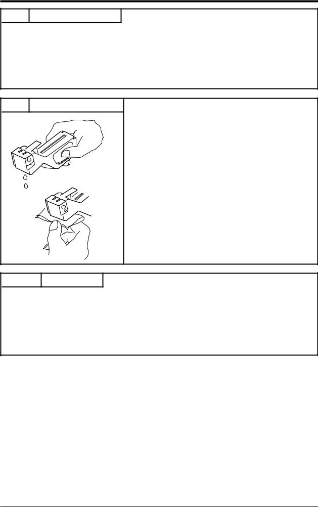
Note 5 If the ink is not sprayed.
Hold the recording head with turning the nozzle surface downward and push the side strong till spilling two drops.
Absorb the standing ink on the nozzle surface with the cloth attached.
Hold the cloth to the nozzle surface again to find the ink flowed onto cloth.
When ink does not come out, repeat the above operation ( through ).
*When working environment is 15°C or less, perform print-out of "record" or "test pattern" after a period or
several minutes has elapsed since the recording head was mounted. (The recording head has a built-in heater.)
Reference Ink consumption
When recording at 20mm/h of chart speed and a given input, the consumption of ink is as shown below, though it depends on operating conditions.
1 continuous recording --------- |
about 20 months |
2 continuous recording --------- |
about 12 months |
6 dot recording ------------------ |
about 8 months |
INP-TN2PHEV-E |
5 - 9 |

6. OPERATION AND ACTIONS
6.1 Before running the equipment:
Check the following points before starting operation.
Setting the chart paper and recording head
Setting the chart paper ..................................................................................... |
See Section 5.1 |
Setting the recording head ............................................................................... |
See Section 5.2 |
Wiring
Input terminals ................................................................................................. |
|
Alarm terminals (option) ................................................................................. |
See Section 4.3 |
Power and earth terminals ............................................................................... |
|
Conformity of input connection to recording channel
Code symbols .................................................................................................. |
See Section 1.3 |
INP-TN2PHEV-E |
6 - 1 |

6.2Turning on power and status
The instrument has no power switch. Engaging the power cord with power source turns it on.
1) Turning on power for the first time
↓
The recording head slowly moves toward the left end (0% side).
↓
After detecting the 0% position, the recording head moves to the approximate central position.
↓
The current time appears on the display section, approximately 30 seconds later in case of 6 dot type.
2)Whether to start recording when turning on is as in “7.11 /Selecting whether to start recording when turning on”.
Prior to delivery of the unit, the recording condition at power ON is set in  “Record Stop” mode. When starting the recording operation at the time of CAUTION recovery of power failure during operation, turn ON the power and set the
unit in “Record Start” mode referring to Item 7-11.
6.3Printing the test pattern
Open the front door and press the DSP key for 3 seconds to display the following.
Press the SEL key two times to display the following.
Press the key until “0” turns “2”.
Press the ENT key to print the test pattern below.
Note 1) Make sure all colours are recorded. If any colour is not developed or is unclear, apply the furnished cloth carefully on the nozzle end to wipe it. (See 5.2, Step 3 ..)
Note 2) To quit print-out, press the ENT key again.
6 - 2 |
INP-TN2PHEV-E |

6.4Operation in normal mode
(1) Stopping and starting the recording operation ( REC key)
• Only in the normal mode, recording can be started or stopped.
• Each press of REC key alternately selects recording operation or recording stop.
|
|
|
|
|
|
|
|
|
|
LED lit |
LED extinguished |
|
|
|
|
|
|
|
|
|
|
|
|
|
|
|
|
|
|
|
|
|
|
|
|
|
|
|
|
|
|
|
|
|
|
|
|
|
|
|
|
|
|
|
|
Recording in progress |
Not recording |
|||||||
|
|
|
|
|
|
|
|
|
|
|
|
|
|
(2) Quick feed of recording chart ( |
FEED |
key) |
|||||||||
• Hold down the FEED key to quickly feed the recording chart, overriding the normal chart speed.
(3) Changing the display mode ( DSP key)
• Pressing the |
|
DSP |
|
key changes the display mode. |
|
|
|
|
|
||
• Each press of |
|
DSP |
key selects the next display mode. |
||
(The number of screens depends on 1 continuous, 2 continuous or 6 dot recording.)
Time display
1 continuous
Measured value
sequential display
DSP
CH1 Measured value fixed display
1 continuous |
DSP |
|
CH2 Measured value fixed display
DSP
2 continuous
CH3 Measured value fixed display
DSP
CH4 Measured value fixed display
DSP
CH5 Measured value fixed display
Sequentially displays ch 1 and subsequent every 3 seconds.
Display ch 1 only.
Display ch 2 only.
Display ch 3 only.
Display ch 4 only.
 Display ch 5 only.
DSP
CH6 Measured value
Display ch 6 only.
fixed display
6 dot
INP-TN2PHEV-E |
6 - 3 |

6.5Displays and print-outs on detection (cancellation) of alarms
When an alarm has occurred, its contents appear on the display section. They appear for 1 second
every 3 seconds while displaying a measured value.
Note) In case of fixed display of measured value, the alarm status for the fixed channel only appears.
Example of alarm display
Example: Alarm No.1 and No.2 of ch 1 has occurred.
When an alarm detected and cancelled, the relevant details are printed on the right-hand side of the
chart paper. |
|
On detection: |
The time of detection, channel No., type of alarm, |
---- Print-out color: Red (6 dot), Red (1,2-continuous)
On cancellation: The time of cancellation, channel No., type of alarm
---- Print-out color: Black (6 dot), Blue (1,2-continuous)
Channel 1 No. 1 H alarm |
|
←release |
|
← |
Release time: 17 : 40 |
|
|
Channel 1 No. 1 H alarm generation
Generating time: 17 : 37
If an alarm is detected or a cancellation is made during data print-out or list print-out, the alarm print-out takes place after completion of the data or list print-out.
Up to a maximum of 30 alarm detection cancellation information can be stored and sequentially printed out, but if the storage capacity is exceeded because of a large number of detections/cancellations in a short time, information in the overflow portion is discarded and cannot be printed out.
6.6Displays and print-outs on occurrent of burnt-out
If a thermocouple or resistance bulb has burnt our, its contents appear.
Example of alarm display
Example: Ch 1 burnt out.
Note: Trend recording overswings toward the maximum side of the recording range.
If a burn-out occurs, its contents are printed on the right of recording chart (in red).
Example of burn-out print-out
1 |
BUNOUT 11 : 52 |
Occurrence time : 11 : 52 |
|
Channel No. : 1 |
|||
|
|
||
|
|
|
6 - 4 |
INP-TN2PHEV-E |
Loading...