


FRN001C1S-2U
Fuji Electric FRN001C1S-2U, FRNF12C1S-2U, FRN002C1S-2U, FRN003C1S-2U, FRN005C1S-2U Brochure
...
Actual size
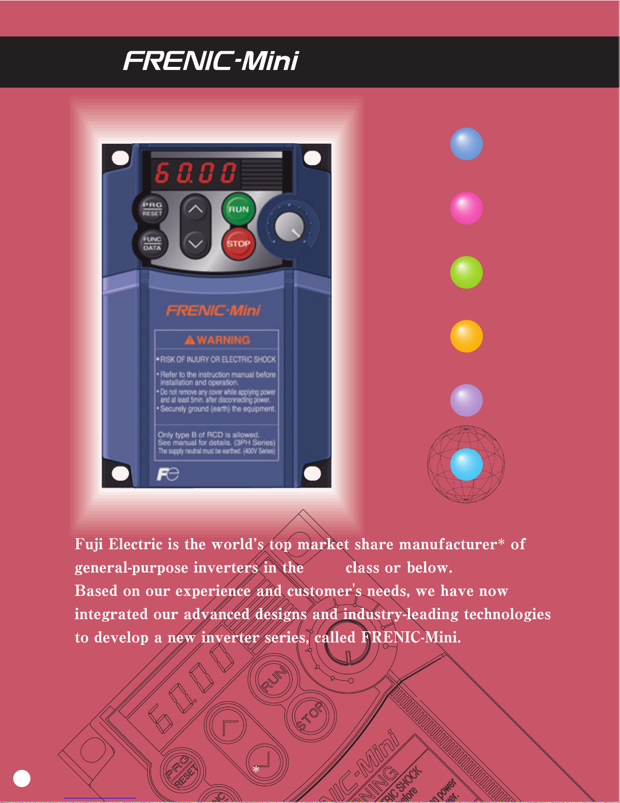
The FRENIC-Mini features a full range of functions, compact body, simple operation, wide model
variations, and global compatibility. It will meet your needs for higher performance in machines and
equipment such as conveyors, fans, pumps, centrifugal separators and food processing machines,
as well as the needs for system integration, energy saving, labor saving, and total cost reduction.
Ideal functions to meet various needs
Flexible through optionals
New, compact design
A broad range of model variations
Simple operation
Global products
Ideal functions to meet various needs
Flexible through optionals
New, compact design
A broad range of model variations
Simple operation
Global products
Series Concepts
5HP
2
Optimum performance for traversing conveyors
Motor speed [r/min]
Torque [%]
0
Motor speed [r/min]
[Instability characteristics]
0
FRENIC-Mini
Conventional Fuji inverter
0
100
50
60
(50)
120
(100)Output frequency [Hz]
Short-time operation torque
Continuous operation
allowable range
Output
torque
[%]
150
6
(5)
100% output torque refers to
the rated torque of the motor
driven at 60 Hz.
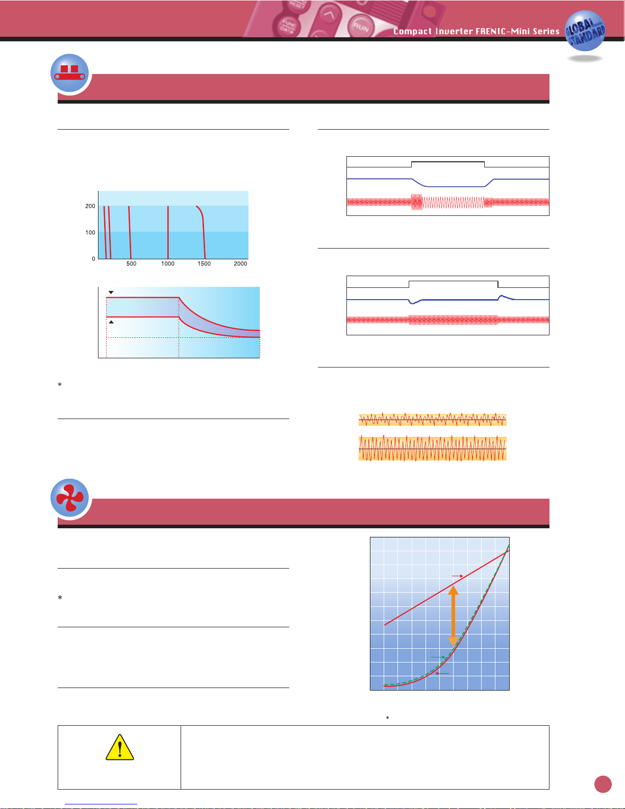
High starting torque, at 150% or more
Equipped with Fuji,s original simplified torque-vector control
system and the automatic torque boost function, the inverter
provides consistent powerful operation (when automatic torque
boost is ON, slip compensation control is ON, and when
running at 5Hz or more).
Trip-free operation
The remarkably improved current limiting function (stall
prevention) allows trip-free operation even for an impact load.
Stable operation even for a step load
The slip compensation function permits stable operation even
when the motor load fluctuates (step load).
Braking resistor connectable to the inverter
Owing to a built-in braking transistor (1/2HP or larger), an optional
braking resistor can be connected to increase the regenerative
braking capacity for conveyance and transportation machinery that
require large braking power. For inverters of 2HP or larger, it is
possible to select the model that incorporates a braking resistor.
Reduced motor instability at low speed
Fuji,s unique control method improves voltage control
performance and reduces motor instability at low speed to about a
half or less (at 1Hz) compared with that of conventional inverters.
Automatic energy-saving provided
as a standard function
By controlling the motor loss to a minimum, FRENIC-Mini
further saves electric power when applied to fans or pumps.
Cooling fan ON/OFF control function
The inverter,s cooling fan can be turned off while the fan or
pump is stopped for noise reduction and energy savings.
PID control function
Permits motor operation while controlling temperature,
pressure, or flow rate without using an external device such as
temperature controller.
The highly used functions for fans and pumps
[Output torque characteristic data]
[Torque characteristics]
Safety Precautions
1. The contents of this catalog are provided to help you select the product model that is best for you. Before actual use, be sure
to read the Instruction Manual/User,s Manual thoroughly to assure correct operation.
2. This product is not designed and manufactured for use in machines or systems which human life is dependent upon. If you
are studying use of the products in this brochure for special purposes such as for control of nuclear power stations, in sea, air
or space craft, in medical or land transportation equipment, or any related systems, please contact the business office of Fuji
Electric. If these products are to be used in any equipment in which there is a risk to human life or the possibility of a major
loss in the event of failure, be sure to install the appropriate safety equipment.
The above graph shows an example of torque characteristics obtained when FRENIC-Mini is
combined one-to-one with Fuji,s standard three-phase motor (8-type series: 4 poles).
Energy saving rate varies with the motor characteristics.
Time
Motor speed
Load torque
Output current
Time
Motor speed
Load torque
Output current
0s 2.5s 5s 7.5s 10s 12.5s
0s 2.5s 5s 7.5s 10s 12.5s
When damper or valve is used
Energy
saved
Inverter control
(Automatic energy-saving mode)
Inverter control
(V/f control)
Air or liquid flow rate Q [%]
Required power P
[%]
110
90
80
70
60
50
40
30
20
10
0201030 40 50 60 70 80 90 100
[Energy savings effect]
Energy savings rate varies with the motor characteristics.
100
3
The ideal functions to serve a multiplicity of needs for small-capacity inverters
A transistor output is provided.
This enables an overload early warning, lifetime forecast or
other information signals to be output during operation.
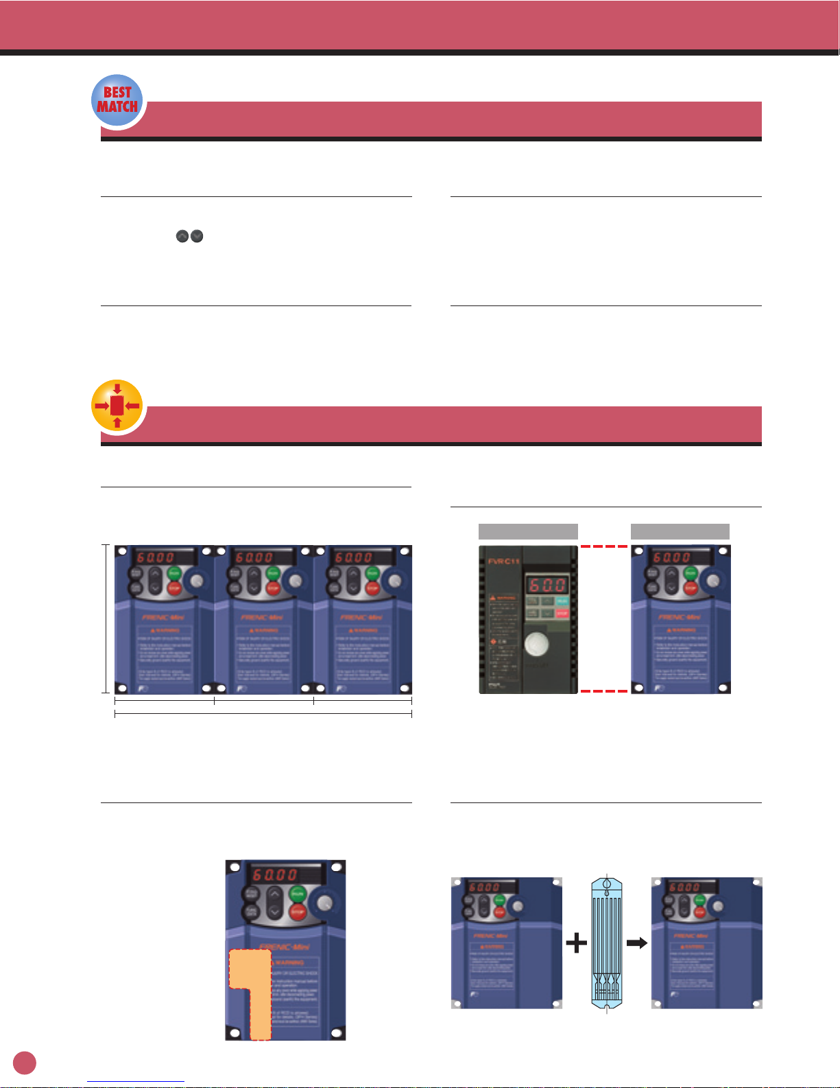
Compact
4.72
(120)
3.15(80) 3.15(80)
9.45(240)
(Units: inch(mm))
(Three-phase 230V, 1HP or less)
(Three-phase 230V, 1HP or less)
(Three-phase 230V, 2HP)
3.15(80)
FVR-C11S FRENIC-Mini
RS-485
communications card
Compatible with a wide range of
frequency settings
The optimum frequency setting method can be selected to
match your machine or equipment. Setting can be done by
keypad panel ( keys, potentiometer), analog input (4 to
20mA, 0 to +10V, 0 to 5V, 1 to 5V), multistep speed settings (8
steps) etc.
Two points can be set for a non-linear
V/f pattern.
One point for the non-linear V/f pattern, which can be set as
desired, has been added (making a total of 2 points), and so
the V/f pattern can be adjusted to match the application.
Side-by-side mounting is possible.
The output frequency can be set to a
maximum of 400Hz.
The inverter can be used for equipment that requires a high
motor speed such as centrifugal separator. In this case, check
the operation in combination with the motor.
RS485 communications card (option)
can be installed internally.
This card can be installed inside the inverter,s body without
changing the dimensions. RS-485 communications are
available as option.
A model with built-in braking resistor is
available on order.
For inverters of 2HP or larger, a built-in braking resistor type
can be selected.
Since installation and wiring of a separate braking resistor is
not required, the total mounting space is reduced.
Size interchangeability with Fuji,s
FVR-C11S series is provided.
Multiple inverter units can be mounted side-by-side inside a
panel. This features helps to minimize the space used for
installation. (Ambient temperature: 40°C (104°F) or less)
4
Phone: 800.894.0412 - Fax: 888.723.4773 - Web: www.ctiautomation.net - Email: info@ctiautomation.net
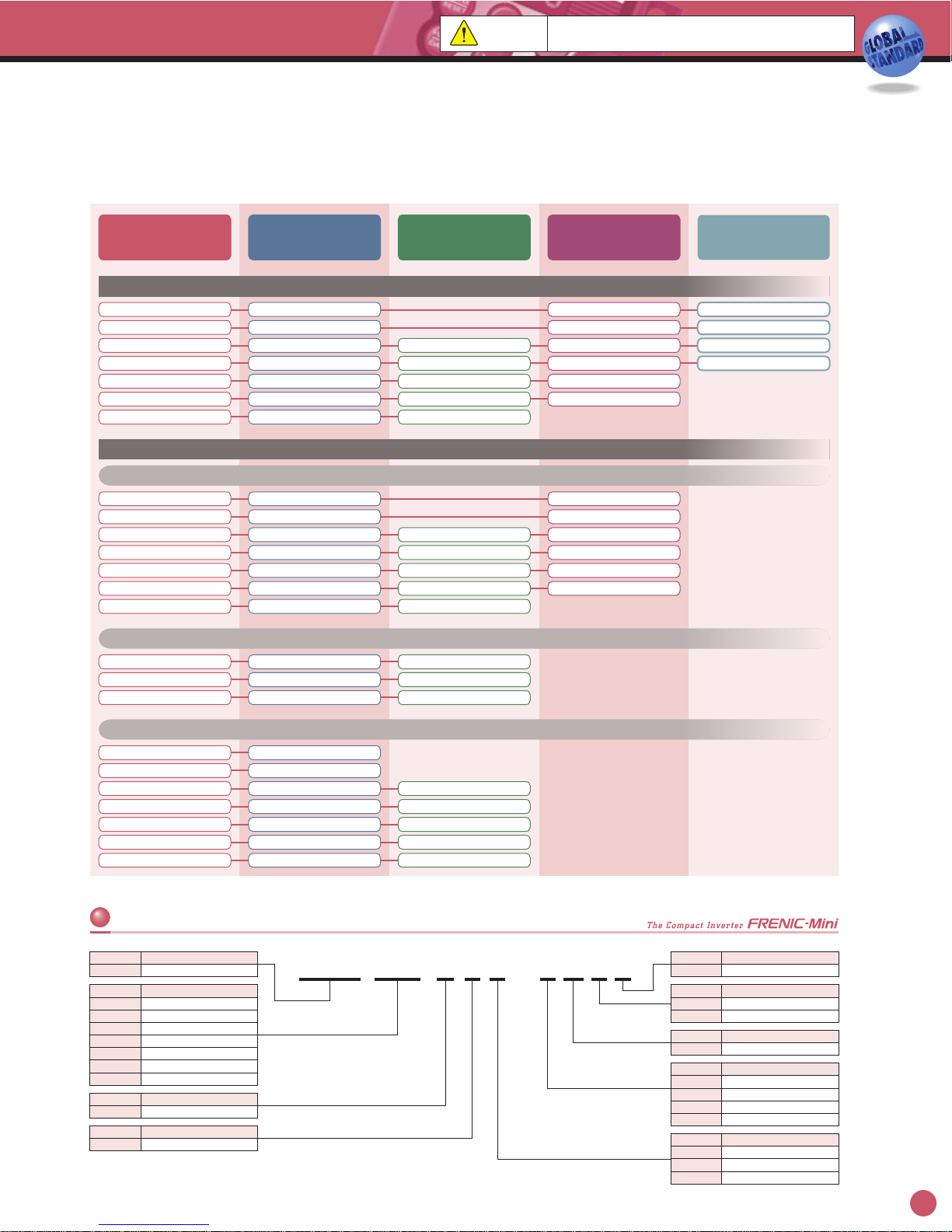
Simple operation and wiring
Frequency setting potentiometer is
standard equipment.
The frequency can be adjusted easily by hand.
A menu mode is included in the keypad.
A long-life cooling fan is included.
Cumulative running time is recorded and displayed.
The inverter records and displays the cumulative running time
(lifetime) of the inverter itself, PCB, and cooling fan.
Input/output phase loss protective function
It is possible to detect output phase loss at all times during
starting and operation.
Sink/Source can be switched.
The input/output mode (Sink/Source) of the digital input terminals
can be switched by means of an internal jumper switch.
The motor can be protected by a PTC thermistor.
In addition to the protection by an electronic thermal relay, the
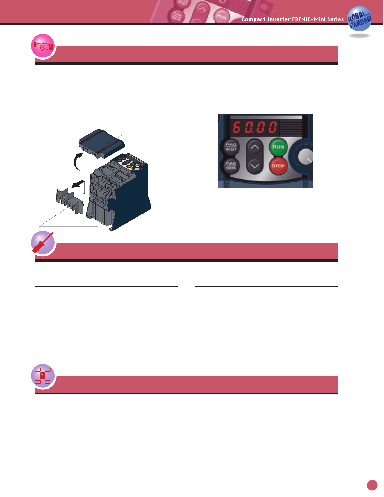
The control circuit terminal block cover
and main circuit terminal block cover
can be quickly removed.
Maintenance
Interface for peripheral devices and comprehensive protective functions
Control circuit terminal block cover
Main circuit terminal block cover
All types of data can be displayed on
the keypad.
The output frequency, set frequency, load shaft speed, output
current, output voltage, alarm history, input power etc. can be
displayed.
The lifetime of the DC bus capacitor can
be estimated.
The capacitor,s condition compared with its initial state can be
confirmed.
All models are equipped with an inrush
current suppression circuit.
An inrush current suppression circuit is provided as standard
in all models, so the cost of peripheral devices such as input
magnetic contactors can be reduced.
A DC reactor (DCR) connection terminal
is provided as standard.
A terminal for connection of a DCR, necessary for suppressing
harmonics, is provided in all models.
The alarm history for the 4 latest
alarms is recorded.
Detailed information from back as far as the 4 latest alarms
can also be checked.
It is possible to output lifetime forecast
signal to the transistor output.
This signal is output when the capacitors in the DC bus circuit,
the electrolytic capacitors on the PCB or the cooling fans are
nearing the end of their service life.
,,
,,
,,
,,
,,
,,
Use of a long-life cooling fan (design life: 7 years with an
ambient temperature: 40°C (104°F) reduces maintenance work.
The menu items include the function menu for checking or
changing function codes, operation monitor , I/O check ,
maintenance info. and alarm info. See the FRENIC-Mini
User,s Manual for details.
,,
,, ,,
,,
5

Flexible through optionals
Remote operation is possible.
Remote operation can be done easily using the optional
RS-485 communications card, remote keypad and remote
operation extension cable.
Function code copy function
The optional remote keypad panel includes a built-in copy
function, so function codes can be set easily in duplicate units.
Mounting on DIN rail
Using the rail mounting base (option), the inverter can be
easily mounted on a DIN rail (35mm wide).
Wide variations
Global products
All standard models comply with the EC Directive (CE marking), UL standards and
Canadian standards (cUL certification).
All standard FRENIC-Mini inverters comply with European and North American/Canadian standards, enabling standardization of the
specifications for machines and equipment used at home and abroad.
If the model with built-in EMC filter is used, the model conforms to the European
EMC Directive.
Replacement of older models
with new ones is simple.
The latest models can be mounted without drilling additional
holes by use of the mouting adapter (option).
Inverter support loader software is
available.
The inverter support loader program (Windows based), which
simplifies setting of function codes, is provided.
The optional RS-485 communications card, remote operation
extension cable and USB-RS-485 converter are necessary.
Europe
North America/Canada
UL standard (cUL certification)EC Directives (CE making), TUV
..
Remote keypad
Extension cable for remote operation
RS-485
communications
card
6
Phone: 800.894.0412 - Fax: 888.723.4773 - Web: www.ctiautomation.net - Email: info@ctiautomation.net
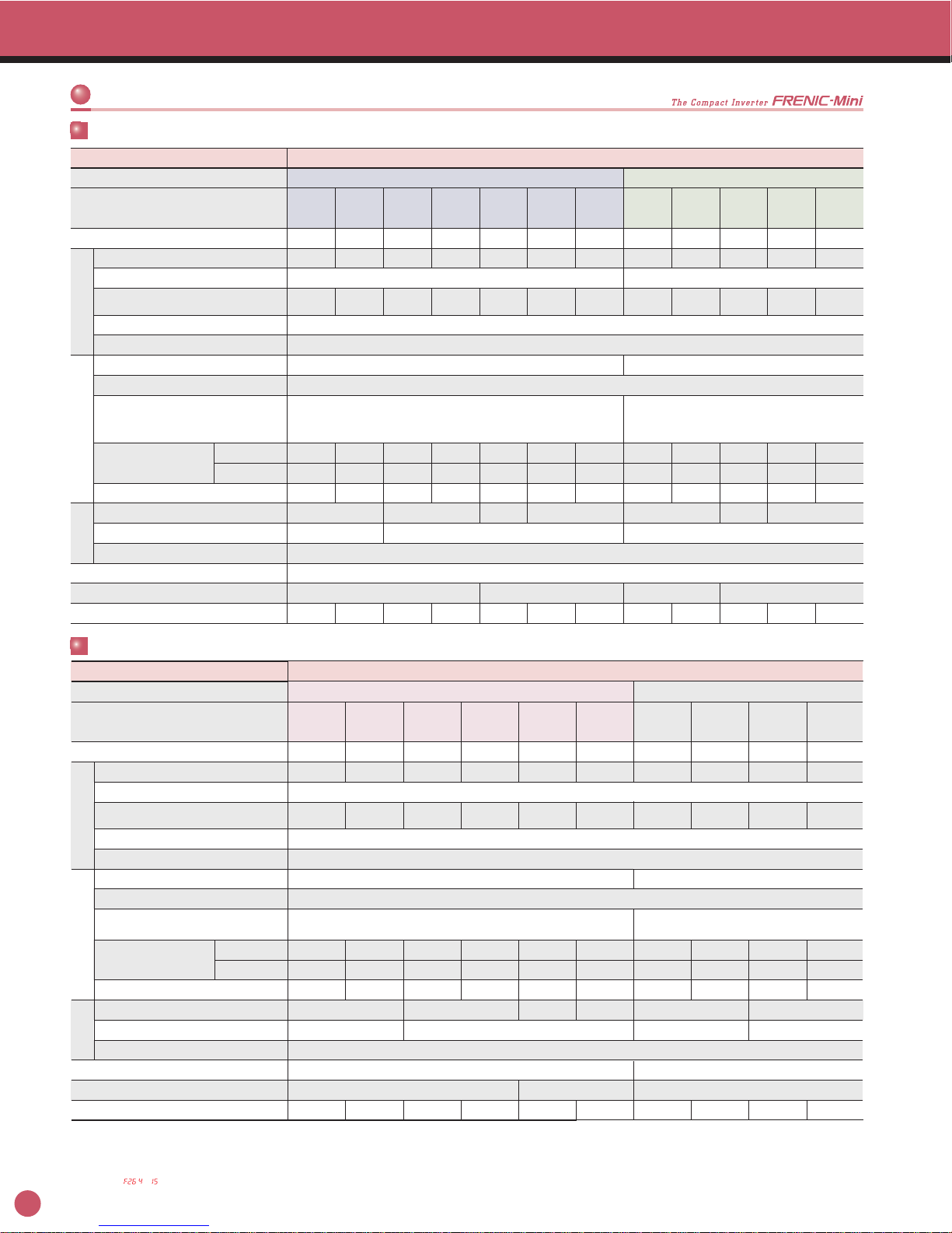
Variation
How to read the model number
FRN 001 C 1 S - 2 U 2 1
Code
FRN
Series name
FRENIC series
Code
Blank,1
Built-in option
None
Code
Blank,1
2
Brake
Standard
Braking resistor built-in type
Code
U
Version/Manual
USA / English
Code
2
4
6
7
Input power source
Three-phase 230V
Three-phase 460V
Single-phase 115V
Single-phase 230V
Code
F12
F25
F50
001
002
003
005
Applicable motor rating
[HP]
1/8
1/4
1/2
1
2
3
5
Code
C
Application range
Compact
Code1Developed inverter series
1
Code
S
E
J
Enclosure
Standard (IP20)
EMC filter built-in type (IP20)
IP40 enclosure type
Standard specifications
1/8
1/4
1/2
1
2
3
5
Applicable
motor rating
FRNF12C1S-2U
FRNF25C1S-2U
FRNF50C1S-2U
FRN001C1S-2U
FRN002C1S-2U
FRN003C1S-2U
FRN005C1S-2U
Three-phase
230V
FRNF50C1S-4U
FRN001C1S-4U
FRN002C1S-4U
FRN003C1S-4U
FRN005C1S-4U
Three-phase
460V
FRNF12C1S-7U
FRNF25C1S-7U
FRNF50C1S-7U
FRN001C1S-7U
FRN002C1S-7U
FRN003C1S-7U
Single-phase
230V
Semi-standard specifications
EMC filter built-in type (On order)
1/8
1/4
1/2
1
2
3
5
FRNF12C1E-2U
FRNF25C1E-2U
FRNF50C1E-2U
FRN001C1E-2U
FRN002C1E-2U
FRN003C1E-2U
FRN005C1E-2U
FRNF50C1E-4U
FRN001C1E-4U
FRN002C1E-4U
FRN003C1E-4U
FRN005C1E-4U
IP40 enclosure type
1/8
1/4
1/2
1
2
3
5
FRNF12C1J-2U
FRNF25C1J-2U
FRNF50C1J-2U
FRN001C1J-2U
FRN002C1J-2U
FRN003C1J-2U
FRN005C1J-2U
FRNF50C1J-4U
FRN001C1J-4U
FRN002C1J-4U
FRN003C1J-4U
FRN005C1J-4U
FRNF12C1E-7U
FRNF25C1E-7U
FRNF50C1E-7U
FRN001C1E-7U
FRN002C1E-7U
FRN003C1E-7U
Braking resistor built-in type (On order)
2
3
5
FRN002C1S-2U21
FRN003C1S-2U21
FRN005C1S-2U21
FRN002C1S-4U21
FRN003C1S-4U21
FRN005C1S-4U21
Caution
The contents of this catalog are provided to help you select the
product model that is best for you. Before actual use, be sure to read
the User's Manual thoroughly to assure correct operation.
In addition to the three-phase 230V, single-phase 230V and single-phase 115V,
three-phase 460V has been newly introduced, broadening the model selection
range.
Model variations include EMC filter built-in type and braking resistor built-in
type on order.
Note)
If “Built-in option” is “None” and “Brake” is “Standard”, the model numbers are indicated in the same format as those of the above standard specifications.
Type1(NEMA1)conformed model is available by attaching optional parts.
FRNF12C1S-6U
FRNF25C1S-6U
FRNF50C1S-6U
FRN001C1S-6U
Single-phase
115V
7
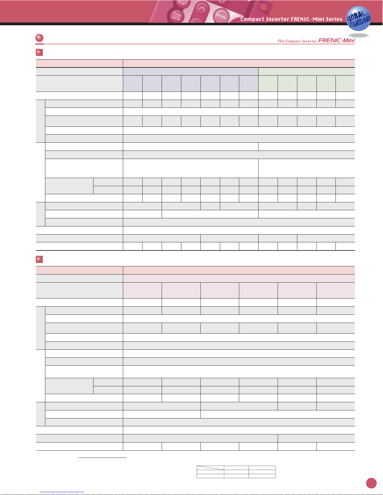
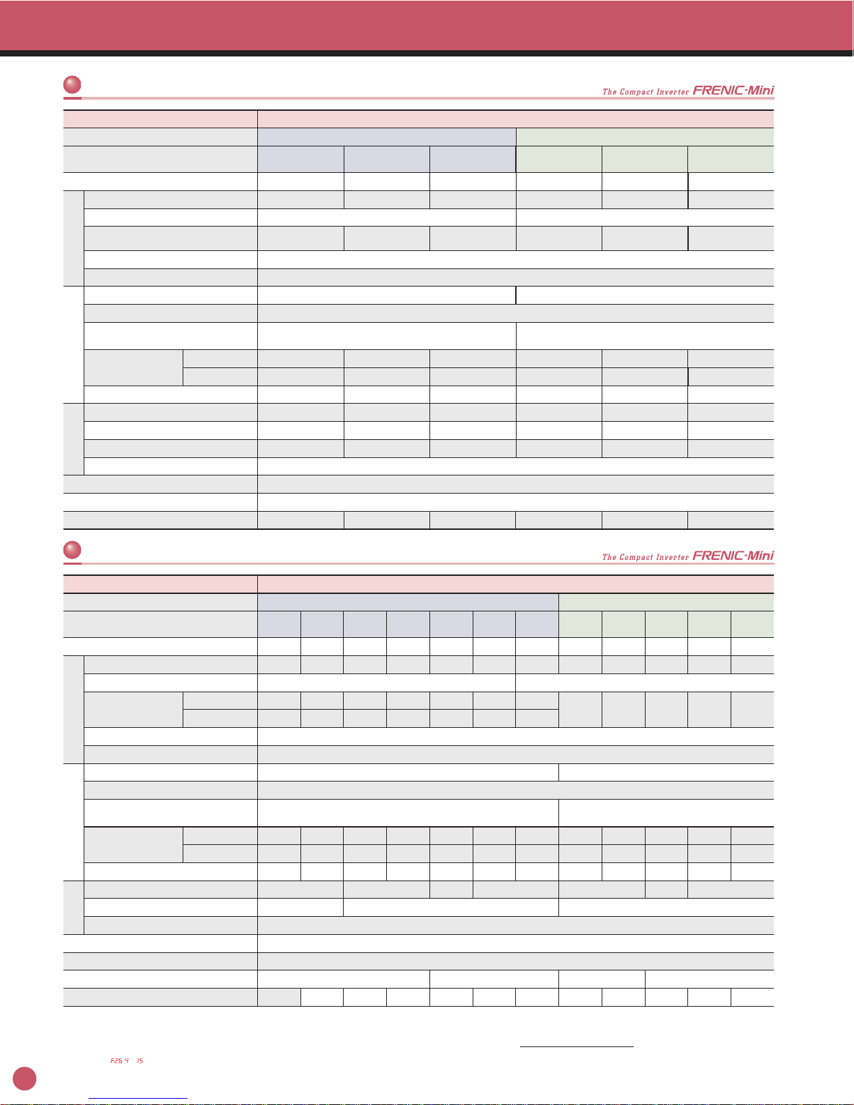
Standard Specifications
Type (FRN
C1S-U)
Applicable motor rating *1) 1/81/41/212351/21235
Enclosure (IEC 60529)
Cooling method
Weight / Mass
IP20, UL open type *11)
Natural cooling
1.3(0.6) 1.3(0.6) 1.3(0.6) 1.5(0.7) 3.7(1.7) 3.7(1.7) 5.1(2.3) 2.4(1.1) 2.6(1.2) 3.7(1.7) 3.7(1.7) 5.1(2.3)
Fan cooling Natural cooling Fan cooling
Rated capacity *2) 0.31 0.59 1.1 1.9 3.1 4.3 6.7 1.1 1.9 2.9 4.3 7.1
Rated current *4) A
%
%
lbs.(kg)
A
HP
kVA
kVA
V
A
%
%
lbs.(kg)
HP
kVA
kVA
V
0.8
(0.7)
1.5
(1.4)
3.0
(2.5)
5.0
(4.2)
8.0
(7.0)
11.0
(10.0)
17.0
(16.5)
1.5 2.5 3.7 5.5 9.0
Rated voltage *3)
Overload capability 150% of rated current for 1min, 200% of rated current for 0.5s
Rated frequency
Phases, voltage, frequency Three-phase, 200 to 240V, 50/60Hz Three-phase, 380 to 480V, 50/60Hz
Voltage/frequency variations
Required power supply capacity *7) 0.2 0.3 0.6 1.1 2.0 2.9 4.9 0.6 1.1 2.0 2.9 4.9
Torque *8) 150 100 50 30 100 50 30
Torque *9)
DC injection braking
-
150 150
Starting frequency: 0.0 to 60.0Hz Braking time: 0.0 to 30.0s Braking level: 0 to 100% of rated current
Voltage: +10 to -15% (Voltage unbalance *10) : 2% or less) Frequency: +5 to -5%
Rated current *6)
Momentary voltage dip capability *5)
(with DCR)
(without DCR)
0.57
1.1
0.93
1.8
1.6
3.1
3.0
5.3
5.7
9.5
8.3
13.2
14.0
22.2
0.85
1.7
1.6
3.1
3.0
5.9
4.4
8.2
7.3
13.0
50, 60Hz
Three-phase, 200V/50Hz, 200, 220, 230V/60Hz
Three-phase, 380, 400, 415V/50Hz, 380, 400, 440, 460V/60Hz
Input power source
FRNF12
C1S-2U
FRNF25
C1S-2U
FRNF50
C1S-2U
FRN001
C1S-2U
FRN002
C1S-2U
FRN003
C1S-2U
FRN005
C1S-2U
FRNF50
C1S-4U
FRN001
C1S-4U
FRN002
C1S-4U
FRN003
C1S-4U
FRN005
C1S-4U
Three-phase 230V
Item Specifications
Three-phase 460V
Output ratingsInput ratingsBraking
Type (FRN
C1S-U)
Applicable motor rating *1) 1/8 1/4 1/2 1 2 3
Enclosure (IEC 60529)
Cooling method
Weight / Mass
IP20, UL open type *11) IP20
Natural cooling
1.3(0.6) 1.3(0.6) 1.3(0.6) 1.8(0.8) 3.7(1.7) 5.1(2.3)
Fan cooling
Rated capacity *2) 0.31 0.59 1.1 1.9 3.1 4.3
Rated current *4)
0.8
(0.7)
1.5
(1.4)
3.0
(2.5)
5.0
(4.2)
8.0
(7.0)
11.0
(10.0)
Rated voltage *3)
Overload capability 150% of rated current for 1 min, 200% of rated current for 0.5s
Rated frequency
Phases, voltage, frequency Single-phase, 200 to 240V, 50/60Hz Single-phase, 100 to 120V, 50/60Hz
Voltage/frequency variations
Required power supply capacity *7) 0.3 0.4 0.7 1.3 2.4 3.5
Torque *8) 150 100 3050
Torque *9)
DC injection braking
-
150
Starting frequency: 0.0 to 60.0Hz Braking time: 0.0 to 30.0s Braking level: 0 to 100% of rated current
Voltage: +10 to -10% Frequency: +5 to -5%
Momentary voltage dip capability *5)
Rated current *6) A
(with DCR)
(without DCR)
1.1
1.8
2.0
3.3
3.5
5.4
6.4
9.7
11.6
16.4
17.5
24.8
50, 60Hz
Three-phase, 200V/50Hz, 200, 220, 230V/60Hz
Input power source
FRNF12
C1S-7U
FRNF25
C1S-7U
FRNF50
C1S-7U
FRN001
C1S-7U
FRN002
C1S-7U
FRN003
C1S-7U
Single-phase 230V Single-phase 115V
*12)
Item Specifications
Output ratingsInput ratingsBraking
*1) Standard 4-pole motor
*2) Rated capacity is calculated by regarding the output rated voltage as 220V for three-phase 230V
and single-phase 230V series, and as 440V for three-phase 460V series.
*3) Output voltage cannot exceed the power supply voltage.
*4) Use the inverter at the current given in ( ) or below when the carrier frequency setting is higher
than 4kHz ( : to ) or the ambient temperature is 40°C (104°F) or higher.
*5) Tested under the standard load condition (85% load for nominal applied motor).
*6) Calculated under Fuji-specified conditions.
*7) Obtained when a DC REACTOR (option) is used.
*8) Average braking torque obtained with AVR control OFF (Varies with the efficiency of the motor.)
*9) Average braking torque obtained by use of external braking resistor (standard type available as option)
Three-phase series
Single-phase series
Standard specifications
When the input voltage is 165V or more, the inverter continues operation. If it
drops below 165V, the inverter operates for 15ms.
When the input voltage is 300V or more, the inverter
continues operation. If it drops below 300V, the inverter
operates for 15ms.
1/8 1/4 1/2 1
1.3(0.6) 1.3(0.6) 1.5(0.7) 2.6(1.2)
Natural cooling
0.26 0.53 0.95 1.6
0.7 1.4 2.5 4.2
0.3 0.5 0.7 1.3
150 100
150
-
2.2
3.6
3.8
5.9
6.4
9.5
12.0
16.1
FRNF12
C1S-6U
FRNF25
C1S-6U
FRNF50
C1S-6U
FRN001
C1S-6U
When the input voltage is 165V or more, the inverter continues operation. If it
drops below 165V, the inverter operates for 15ms.
When the input voltage is 85V or more, the inverter
continues operation. If it drops below 85V, the inverter
operates for 15ms.
8
Phone: 800.894.0412 - Fax: 888.723.4773 - Web: www.ctiautomation.net - Email: info@ctiautomation.net
Semi-standard Specifications
Momentary voltage dip capability *5)
EMC filter built-in type
Three-phase series
Type (FRN
C1E-U)
Applicable motor rating *1) 1/8 1/4 1/2 1 2 3 5 1/2 1 2 3 5
Enclosure (IEC 60529)
Cooling method
Weight / Mass
IP20, UL open type *11)
Natural cooling Fan cooling Natural cooling Fan cooling
Rated capacity *2) 0.31 0.59 1.1 1.9 3.1 4.3 6.7 1.1 1.9 2.9 4.3 7.1
Rated current *4)
0.8
(0.7)
1.5
(1.4)
3.0
(2.5)
5.0
(4.2)
8.0
(7.0)
11.0
(10.0)
17.0
(16.5)
1.5 2.5 3.7 5.5 9.0
Rated voltage *3)
Overload capability 150% of rated current for 1min, 200% of rated current for 0.5s
Rated frequency
Phases, voltage, frequency Three-phase, 200 to 240V, 50/60Hz Three-phase, 380 to 480V, 50/60Hz
Voltage/frequency variations
Required power supply capacity *7) 0.2 0.3
1.5(0.7) 1.5(0.7) 1.5(0.7) 1.8(0.8) 5.3(2.4) 5.3(2.4) 6.4(2.9) 3.3(1.5) 3.7(1.6) 5.5(2.5) 5.5(2.5) 6.6(3.0)
0.6 1.1 2.0 2.9 4.9 0.6 1.1 2.0 2.9 4.9
Torque *8) 150 100
50 30 100 50 30
Torque *9)
DC injection braking
- 150 150
Starting frequency: 0.0 to 60.0Hz Braking time: 0.0 to 30.0s Braking level: 0 to 100% of rated current
Voltage: +10 to -15% (Voltage unbalance *10) : 2% or less) Frequency: +5 to -5%
Rated current *6)
(with DCR)
(without DCR)
0.57
1.1
0.93
1.8
1.6
3.1
3.0
5.3
5.7
9.5
8.3
13.2
14.0
22.2
0.85
1.7
1.6
3.1
3.0
5.9
4.4
8.2
7.3
13.0
50, 60Hz
Three-phase, 200V/50Hz, 200, 220, 230V/60Hz
Three-phase, 380, 400, 415V/50Hz, 380, 400, 440, 460V/60Hz
Input power source
FRNF12
C1E-2U
FRNF25
C1E-2U
FRNF50
C1E-2U
FRN001
C1E-2U
FRN002
C1E-2U
FRN003
C1E-2U
FRN005
C1E-2U
FRNF50
C1E-4U
FRN001
C1E-4U
FRN002
C1E-4U
FRN003
C1E-4U
FRN005
C1E-4U
Three-phase 230V
Item Specifications
Three-phase 460V
Output ratingsInput ratingsBraking
Type (FRN
C1E-U)
Applicable motor rating *1) 1/8 1/4 1/2 1 2 3
Enclosure (IEC 60529)
Cooling method
Weight / Mass
IP20, UL open type *11)
Natural cooling Fan cooling
Rated capacity *2) 0.31 0.59 1.1 1.9 3.1 4.3
Rated current *4)
0.8
(0.7)
1.5
(1.4)
3.0
(2.5)
5.0
(4.2)
8.0
(7.0)
11.0
(10.0)
Rated voltage *3)
Overload capability 150% of rated current for 1min, 200% of rated current for 0.5s
Rated frequency
Phases, voltage, frequency Single-phase, 200 to 240V, 50/60Hz
Voltage/frequency variations
Required power supply capacity *7) 0.3 0.4 0.7 1.3 2.4 3.5
1.5(0.7) 1.5(0.7) 1.5(0.7) 2.6(1.2) 5.3(2.4) 6.4(2.9)
Torque *8) 150 100 30
50
Torque *9)
DC injection braking
-
150
Starting frequency: 0.0 to 60.0Hz Braking time: 0.0 to 30.0s Braking level: 0 to 100% of rated current
Voltage: +10 to -10%, Frequency: +5 to -5%
Momentary voltage dip capability *5)
Rated current *6)
(with DCR)
(without DCR)
1.1
1.8
2.0
3.3
3.5
5.4
6.4
9.7
11.6
16.4
17.5
24.8
When the input voltage is 165V or more, the inverter continues operation. If it drops below 165V,
the inverter operates for 15ms.
50, 60Hz
Three-phase, 200V/50Hz, 200, 220, 230V/60Hz
Input power source
FRNF12
C1E-7U
FRNF25
C1E-7U
FRNF50
C1E-7U
FRN001
C1E-7U
FRN002
C1E-7U
FRN003
C1E-7U
Single-phase 230V
Item Specifications
Output ratingsInput ratingsBraking
kVA
A
%
%
lbs.(kg)
A
HP
kVA
kVA
V
A
%
%
lbs.(kg)
HP
kVA
A
Max voltage [V] - Min voltage [V]
Three-phase average voltage [V]
x 67 (IEC 61800-3 (5.2.3))
Single-phase series
When the input voltage is 165V or more, the inverter continues operation. If it
drops below 165V, the inverter operates for 15ms.
When the input voltage is 300V or more, the inverter
continues operation. If it drops below 300V, the
inverter operates for 15ms.
*10) Voltage unbalance [%] =
If this value is 2 to 3%, use AC REACTOR (ACR).
*11) NEMA1 kit (option) is required for the enclosure conforming to the UL standard TYPE1 (NEMA1).
Use the inverter in the ambient temperature range from -10 to +40
°C (14 to 104°F)
.
*12) When driven by 100 VAC, the single-phase 115 V class series of inverters limit their shaft output and maximum
output torque as listed below. This is to prevent their output voltage from decreasing when load is applied.
Shaft output (%) Maximum torque (%)
w/o DC reactor (DCR) 90 150
w/ DC reactor (DCR) 85 120
9
Phone: 800.894.0412 - Fax: 888.723.4773 - Web: www.ctiautomation.net - Email: info@ctiautomation.net
Semi-standard Specifications
IP40 enclosure type
Type (FRN
C1J-U)
Applicable motor rating *1) 1/8
Enclosure (IEC 60529)
Cooling method
Weight / Mass
IP 40
Starting frequency: 0.0 to 60.0Hz Braking time: 0.0 to 30.0s Braking level: 0 to 100% of rated current
Natural cooling Fan cooling Fan coolingNatural cooling
Rated capacity *2) 0.31
Rated current
0.7
Rated voltage *3)
Overload capability 150% of rated current for 1min, 200% of rated current for 0.5s
Rated frequency
Phases, voltage, frequency Three-phase, 200 to 240V, 50/60Hz Three-phase, 380 to 480V, 50/60Hz
Voltage/frequency variations
Required power supply capacity *7) 0.2
150
-
1.5(0.7)
Torque *8)
Torque *9)
DC injection braking
Applicable safety standards UL508C, C22.2No.14, EN50178:1997 or equivalent
Voltage: +10 to -15% (Voltage unbalance : 2% or less *10) ) Frequency: +5 to -5%
Momentary voltage dip capability *5)
Rated input current *6)
(with DCR)
(without DCR)
High carrier (4-15kHz)
Low carrier (-3kHz)
0.57
1.1
50, 60Hz
Three-phase, 200V/50Hz, 200, 220, 230V/60Hz Three-phase, 380, 400, 415V/50Hz, 380, 400, 440, 460V/60Hz
Input power source
FRNF12
C1J-2U
1/4
0.59
1.4
0.3
1.5(0.7)
0.93
1.8
FRNF25
C1J-2U
1/2
1.1
2.5
0.6
100
150
1.5(0.7)
1.6
3.1
FRNF50
C1J-2U
1
1.9
4.2
1.1
1.8(0.8)
3.0
5.3
FRN001
C1J-2U
2
3.1
7.0
2.0
50
4.8(1.8)
5.7
9.5
FRN002
C1J-2U
3
4.3
10.0
2.9
30
4.8(1.8)
8.3
13.2
FRN003
C1J-2U
FRN005
C1J-2U
FRNF50
C1J-2U
FRN001
C1J-2U
FRN002
C1J-2U
FRN003
C1J-2U
FRN005
C1J-2U
5
6.7
16.5
4.9
5.3(2.4)
14.0
22.2
1/2
1.1
1.5
0.6
100
150
2.6(1.2)
0.85
1.7
1
1.9
2.5
1.1
2.9(1.3)
1.6
3.1
2
2.9
3.7
2.0
50
4.0(1.8)
3.0
5.9
3
4.3
5.5
2.9
30
4.0(1.8)
4.4
8.2
5
7.1
9.0
0.8 1.5 3.0 5.0 8.0 11.0 17.0
4.9
5.3(2.4)
7.3
13.0
Three-phase 230V
Item Specifications
Three-phase 460V
Output ratingsInput ratings
Braking
When the input voltage is 165V or more, the inverter continues operation. If it
drops below 165V, the inverter operates for 15ms.
When the input voltage is 300V or more, the inverter
continues operation. If it drops below 300V, the inverter
%
A
A
%
%
lbs.(kg)
HP
kVA
kVA
V
Braking resistor built-in type
Type (FRN
C1S-U21)
Applicable motor rating *1) 235235
Enclosure (IEC 60529)
Cooling method
Weight / Mass
IP20, UL open type *11)
Fan cooling
Rated capacity *2) 3.1 4.3 6.7 2.9 4.3 7.1
Rated current *4)
8.0
(7.0)
11.0
(10.0)
17.0
(16.5)
3.7 5.5 9.0
Rated voltage *3)
Overload capability 150% of rated current for 1min, 200% of rated current for 0.5s
Rated frequency
Phases, voltage, frequency Three-phase, 200 to 240V, 50/60Hz Three-phase, 380 to 480V, 50/60Hz
Voltage/frequency variations
Required power supply capacity *7) 2.0 2.9
150 100 100 150 100 100
18 12 8 18 12 8
321.5321.5
4.9 2.0 2.9 4.9
4.0(1.8) 4.0(1.8) 5.5(2.5) 4.0(1.8) 4.0(1.8) 5.5(2.5)
Torque *8)
Braking time
Duty cycle
DC injection braking Starting frequency: 0.0 to 60.0Hz Braking time: 0.0 to 30.0s Braking level: 0 to 100% of rated current
Voltage: +10 to -15% (Voltage unbalance *10) : 2% or less) Frequency: +5 to -5%
Momentary voltage dip capability *5)
Rated current *6)
(with DCR)
(without DCR)
5.7
9.5
8.3
13.2
14.0
22.2
3.0
5.9
4.4
8.2
7.3
13.0
50, 60Hz
Three-phase, 200V/50Hz, 200, 220, 230V/60Hz Three-phase, 380, 400, 415V/50Hz, 380, 400, 440, 460V/60Hz
Input power source
FRN002
C1S-2U21
FRN003
C1S-2U21
FRN005
C1S-2U21
FRN002
C1S-4U21
FRN003
C1S-4U21
FRN005
C1S-4U21
Three-phase 230V
Item Specifications
Three-phase 460V
Output ratingsInput ratings
Braking
When the input voltage is 165V or more, the inverter continues
operation. If it drops below 165V, the inverter operates for 15ms.
When the input voltage is 300V or more, the inverter continues
operation. If it drops below 300V, the inverter operates for 15ms.
A
s
A
%
%
lbs.(kg)
HP
kVA
kVA
V
*1) Standard 4-pole motor
*2) Rated capacity is calculated by regarding the output rated voltage as 220V for three-phase 230V
series, and as 440V for three-phase 460V series.
*3) Output voltage cannot exceed the power supply voltage.
*4) Use the inverter at the current given in ( ) or below when the carrier frequency setting is higher
than 4kHz ( : to ) or the ambient temperature is 40°C (104°F) or higher.
*5) Calculated under the standard overload conditions by JEMA committee (about 85% of overload
by the standard applicable motor.)
*6) Calculated under Fuji-specified conditions.
*7) Obtained when a DC reactor (DCR) is used.
*8) Average braking torque obtained with AVR control OFF (Varies with the efficiency of the motor.)
*9) Average braking torque obtained by use of external braking resistor (optional)
*10) Voltage unbalance [%] =
If this value is 2 to 3%, use AC reactor (option).
*11) NEMA1 kit (option) is required for the enclosure conforming to the UL standard TYPE1 (NEMA1).
Use the inverter in the ambient temperature range from -10 to +40°C (14 to 104°F).
Max voltage [V] - Min voltage [V]
Three-phase average voltage [V]
x 67 (Refer to IEC 61800-3.)
10
 Loading...