


 Loading...
Instruction Manual
OPC-G1-ETH
Multiprotocol Ethernet Interface
Thank you for purchasing the OPC-G1-ETH Multiprotocol Ethernet Interface.
•This product is designed to connect the FRENIC-Mega series of inverters to Ethernet communication networks. Please read this instruction manual thoroughly in order to become familiar with the proper interface handling, installation and usage procedures.
•Improper handling may inhibit correct operation or cause premature interface failure.
•Please deliver this instruction manual to the end user of the interface, and retain it in an accessible location.
•For inverter usage instructions, please refer to the applicable inverter instruction manual.
December 6, 2013 |
© 2013 Fuji Electric |
Part #10821 |

OPC-G1-ETH Multiprotocol Ethernet Interface Instruction Manual
Part Number 10821
Printed in U.S.A.
©2013 Fuji Electric.
All rights reserved
Fuji Electric reserves the right to make changes and improvements to its products without providing notice.
Notice to Users
PRODUCTS ARE NOT AUTHORIZED FOR USE AS CRITICAL COMPONENTS IN LIFE-SUPPORT DEVICES OR SYSTEMS. Life-support devices or systems are devices or systems intended to sustain life, and whose failure to perform, when properly used in accordance with instructions for use provided in the labeling and user's manual, can be reasonably expected to result in significant injury.
No complex software or hardware system is perfect. Bugs may always be present in a system of any size. In order to prevent danger to life or property, it is the responsibility of the system designer to incorporate redundant protective mechanisms appropriate to the risk involved.
1

Preface
Thank you for purchasing the OPC-G1-ETH Multiprotocol Ethernet Interface. This instruction manual has been prepared to help you connect your FRENIC-Mega inverter to a variety of Ethernet control networks.
This instruction manual does not contain inverter usage instructions. Please refer to this instruction manual in conjunction with the applicable inverter instruction manual in order to become familiar with the proper handling, installation and operation of this product. Improper handling or installation procedures may result in incorrect operation or premature product failure.
Please keep this instruction manual in a safe place.
Related Publications
Listed below are publications that are recommended for reference in conjunction with this instruction manual.
•RS-485 Communication User's Manual...........(MEH448)
•FRENIC-Mega Instruction Manual...................(INR-SI47-1457-E)
These documents are subject to change without notice. Please be sure to refer to the most recent available versions.
Safety precautions
Please read this instruction manual thoroughly prior to proceeding with installation, connections, operation, or maintenance and inspection. Additionally, ensure that all aspects of the system are fully understood, and familiarize yourself with all safety information and precautions before operating the inverter.
Safety precautions in this instruction manual are classified into the following two categories:
Failure to heed the information indicated by this symbol may lead to dangerous conditions, possibly resulting in death or serious bodily injuries.
Failure to heed the information indicated by this symbol may lead to dangerous conditions, possibly resulting in minor or light bodily injuries and/or substantial property damage.
Failure to heed the information contained under the CAUTION title can also result in serious consequences. These safety precautions are of utmost importance and must be observed at all times.
2

Installation and wiring
•To avoid electrical shock, remove all power from the inverter and wait at least five minutes prior to starting installation. Additionally, confirm that the DC link bus voltage as measured between the P
(+) and N (-) terminals is less than 25 VDC.
•Installation should be performed only by qualified personnel.
•To avoid electrical shock, do not operate the inverter with the front cover or wiring cover removed, as accidental contact with exposed high-voltage terminals and internal components may occur.
•To prevent explosions or similar damage, ensure that all cables are properly connected to the correct terminals, and observe all wiring polarity indicators.
•Do not install or operate the interface if it is damaged or has parts missing.
•Prevent conductive items such as screws and metal fragments, or flammable substances such as oil, lint, paper fibers and sawdust from entering the inverter and interface card enclosure.
•Incorrect handling during installation or removal may cause equipment failure.
•Do not subject the cables to scratches, excessive stress, heavy loads or pinching.
•To prevent damage due to electrostatic discharge, always touch a grounded piece of metal prior to touching any equipment.
•Do not stand on or rest heavy objects on the equipment.
•To prevent burns from hot components, do not touch the inverter while power is on, or for some time after power is removed.
•Electrical noise may be emitted from the inverter, motor and wires. Always implement appropriate countermeasures to prevent nearby sensors and devices from malfunctioning due to such noise.
Operation
•To avoid electrical shock, do not open the front cover of the inverter while power is on or while the inverter is running.
•To avoid electrical shock, do not operate switches with wet hands.
•If the inverter’s function codes are incorrectly configured, or configured without adequate understanding of the appropriate inverter Instruction Manual and User's Manual, the motor may rotate with a torque or at a speed not permitted for the machine. Confirm the settings of all function codes prior to running the inverter.
3

Maintenance, inspection, and parts replacement
•To avoid electrical shock, remove all power from the inverter and wait at least five minutes prior to starting inspection. Additionally, confirm that the DC link bus voltage as measured between the P
(+) and N (-) terminals is less than 25 VDC.
•Maintenance, inspection, and parts replacement should be performed only by qualified personnel.
•Remove all watches, rings and other metallic objects prior to starting work.
•To avoid electrical shock or other injuries, always use insulated tools.
Disposal
•Contact the local or state environmental agency in your area for details on the disposal of electrical components and packaging.
Other
•Do not attempt to modify the equipment: doing so may cause electrical shock or injuries.
•For clarity purposes, illustrations in this manual may be drawn with covers or safety guards removed. Ensure all covers and safety guards are properly installed prior to starting operation.
•Do not perform hi-pot tests on the equipment.
•Performing a data initialization (function code H03) may reset all inverter function codes to their factory default settings. After performing this operation, remember to reenter any custom function code values prior to starting operation.
Icons
The following icons are used throughout this manual:
Indicates information which, if not heeded, can result in the product not operating to full efficiency, as well as information concerning incorrect operations and settings which may result in accidents.
Indicates information that can prove handy when performing certain settings or operations.
Indicates a reference to more detailed information.
4

|
|
|
− TABLE OF CONTENTS − |
|
1 |
PRE-OPERATION INSTRUCTIONS............................................................. |
8 |
||
|
1.1 |
Product Overview.................................................................................................... |
8 |
|
|
1.2 |
Unpacking and Product Confirmation .................................................................. |
9 |
|
|
1.2.1 |
Shipment Confirmation....................................................................................................... |
9 |
|
|
1.2.2 |
Component Overview....................................................................................................... |
10 |
|
|
1.3 |
LED Indicators....................................................................................................... |
12 |
|
|
1.3.1 |
Network Status LED......................................................................................................... |
12 |
|
|
1.3.2 |
Module Status LED .......................................................................................................... |
12 |
|
|
1.3.3 |
Ethernet Link/Activity LEDs.............................................................................................. |
12 |
|
|
1.3.4 |
Ethernet Speed LEDs ...................................................................................................... |
12 |
|
|
1.4 |
Environmental Specifications.............................................................................. |
12 |
|
2 |
INSTALLATION.......................................................................................... |
13 |
||
|
2.1 |
Pre-Installation Instructions................................................................................. |
13 |
|
|
2.2 |
Installation Procedure .......................................................................................... |
13 |
|
3 INVERTER FUNCTION CODE SETTINGS ................................................ |
15 |
|||
|
3.1 |
Inverter Control-Related Settings........................................................................ |
15 |
|
|
3.2 |
Inverter Reaction to Network Timeout Conditions ............................................ |
16 |
|
4 |
FUJI FINDER APPLICATION..................................................................... |
17 |
||
|
4.1 |
Installation ............................................................................................................. |
17 |
|
|
4.2 |
USB Driver Installation ......................................................................................... |
20 |
|
|
4.2.1 |
Windows XP .................................................................................................................... |
20 |
|
|
4.2.2 |
Windows 7 ....................................................................................................................... |
23 |
|
|
4.3 |
Overview ................................................................................................................ |
24 |
|
|
4.4 |
Ethernet Tab .......................................................................................................... |
25 |
|
|
4.5 |
USB Tab ................................................................................................................. |
25 |
|
|
4.6 |
Configuring the IP Address.................................................................................. |
25 |
|
5 |
EMBEDDED WEB SERVER....................................................................... |
26 |
||
|
5.1 |
Overview ................................................................................................................ |
26 |
|
|
5.2 |
Page Select Tabs................................................................................................... |
27 |
|
|
5.3 |
Monitor Tab............................................................................................................ |
27 |
|
|
5.3.1 |
Information Window ......................................................................................................... |
27 |
|
|
5.3.2 Function Code Group Selection List................................................................................. |
27 |
||
|
5.3.3 |
Function Code List ........................................................................................................... |
28 |
|
|
5.3.4 Function Code List Filter .................................................................................................. |
29 |
||
|
5.3.5 |
Radix Selection................................................................................................................ |
29 |
|
|
5.4 |
BACnet Tab............................................................................................................ |
30 |
|
|
5.4.1 |
Information Window ......................................................................................................... |
30 |
|
|
5.4.2 |
Device Identifiers ............................................................................................................. |
30 |
|
|
5.4.3 |
Submitting Changes......................................................................................................... |
31 |
|
|
5.4.4 |
Reinitialize Prompt ........................................................................................................... |
31 |
|
|
5.5 |
Config Tab.............................................................................................................. |
32 |
|
|
5.5.1 |
Information Window ......................................................................................................... |
32 |
|
|
5.5.2 |
Authentication Configuration ............................................................................................ |
32 |
|
5 |
|
|
|
|

5.5.3 |
Timeout Configuration...................................................................................................... |
32 |
|
5.5.4 |
Submitting Changes......................................................................................................... |
33 |
|
5.5.5 |
Reinitialize Prompt ........................................................................................................... |
33 |
|
5.6 |
EtherNet/IP Tab ..................................................................................................... |
34 |
|
5.6.1 |
Information Window ......................................................................................................... |
34 |
|
5.6.2 |
Device Identification......................................................................................................... |
34 |
|
5.6.3 |
Run/Idle Flag Behavior..................................................................................................... |
34 |
|
5.6.4 |
Class 1 (I/O) Data Configuration Arrays ........................................................................... |
35 |
|
5.6.5 |
Submitting Changes......................................................................................................... |
36 |
|
5.6.6 |
Reinitialize Prompt ........................................................................................................... |
36 |
|
5.7 |
Modbus Tab ........................................................................................................... |
37 |
|
5.7.1 |
Information Window ......................................................................................................... |
37 |
|
5.7.2 |
Supervisory Timer Selection ............................................................................................ |
37 |
|
5.7.3 |
Register Remap Configuration......................................................................................... |
38 |
|
5.7.4 |
Submitting Changes......................................................................................................... |
39 |
|
5.7.5 |
Reinitialize Prompt ........................................................................................................... |
39 |
|
5.8 |
Alarm Tab............................................................................................................... |
40 |
|
5.8.1 |
Information Window ......................................................................................................... |
40 |
|
5.8.2 |
Email Configuration.......................................................................................................... |
41 |
|
5.8.3 |
Alarm Configuration ......................................................................................................... |
42 |
|
5.8.4 |
Submitting Changes......................................................................................................... |
43 |
|
5.8.5 |
Reinitialize Prompt ........................................................................................................... |
43 |
|
5.9 |
Dashboard Tab ...................................................................................................... |
44 |
|
5.9.1 |
Information Window ......................................................................................................... |
44 |
|
5.9.2 |
Virtual Keypad.................................................................................................................. |
45 |
|
5.9.3 |
Gauge Window Navigation............................................................................................... |
46 |
|
5.9.4 |
Gauge Window Configuration .......................................................................................... |
46 |
|
5.9.5 |
Submitting Changes......................................................................................................... |
49 |
|
5.10 Customizing the Embedded Web Server ............................................................ |
50 |
||
5.10.1 |
Customization Overview .................................................................................................. |
50 |
|
5.10.2 |
XTPro Overview............................................................................................................... |
50 |
|
5.10.3 |
XTPro Web Browser-Based Implementation.................................................................... |
51 |
|
5.10.4 |
XTPro HMI-Based Implementation................................................................................... |
52 |
|
5.10.5 |
XTPro Supported Commands .......................................................................................... |
52 |
|
6 FUNCTION CODE NUMBERING AND BEHAVIOR................................... |
53 |
|
6.1 |
Register Numbers ................................................................................................. |
53 |
6.2 |
Scanned Function Codes ..................................................................................... |
55 |
6.3 |
Commonly Used Function Codes........................................................................ |
55 |
7 FILE SYSTEM & FIRMWARE .................................................................... |
57 |
|
7.1 |
Overview ................................................................................................................ |
57 |
7.2 |
Windows Explorer................................................................................................. |
58 |
7.3 |
Loading New Application Firmware .................................................................... |
59 |
7.4 |
Loading New Web Server Content ...................................................................... |
60 |
8 PROTOCOL-SPECIFIC INFORMATION .................................................... |
61 |
|
8.1 |
Modbus/TCP .......................................................................................................... |
61 |
8.1.1 Overview.......................................................................................................................... |
61 |
|
8.1.2 Coil & Discrete Input Mappings........................................................................................ |
62 |
|
8.2 |
EtherNet/IP............................................................................................................. |
63 |
|
|
6 |

|
8.2.1 |
Overview.......................................................................................................................... |
63 |
|
|
8.2.2 |
ControlLogix Examples: Setup......................................................................................... |
64 |
|
|
8.2.3 |
ControlLogix Example: I/O Messaging ............................................................................. |
65 |
|
|
8.2.4 |
ControlLogix Example: Generic Default I/O Add-On Instruction ....................................... |
68 |
|
|
8.2.5 |
ODVA AC/DC Drive Profile .............................................................................................. |
71 |
|
|
8.2.6 |
ControlLogix Example: AC/DC Drive Profile Add-On Instruction ...................................... |
73 |
|
|
8.2.7 |
Explicit Messaging Tag Reference................................................................................... |
75 |
|
|
8.2.8 |
ControlLogix Explicit Messaging Example: Read a Function Code Block......................... |
76 |
|
|
8.2.9 |
ControlLogix Explicit Messaging Example: Read a Single Function Code ....................... |
81 |
|
|
8.2.10 |
ControlLogix Explicit Messaging Example: Multiple MSG Instructions ............................. |
81 |
|
|
8.2.11 |
ControlLogix Explicit Messaging Example: Reading and Writing...................................... |
82 |
|
|
8.3 |
Allen Bradley CSP................................................................................................. |
83 |
|
|
8.3.1 |
Overview.......................................................................................................................... |
83 |
|
|
8.3.2 |
Tag Reference ................................................................................................................. |
83 |
|
|
8.3.3 |
SLC-5/05 Example: Read a Register Block...................................................................... |
85 |
|
|
8.3.4 |
SLC-5/05 Example: Read a Single Register..................................................................... |
88 |
|
|
8.3.5 |
SLC-5/05 Example: Multiple MSG Instructions................................................................. |
89 |
|
|
8.3.6 |
SLC-5/05 Example: Reading and Writing......................................................................... |
90 |
|
|
8.4 |
BACnet/IP............................................................................................................... |
91 |
|
|
8.4.1 |
Protocol Implementation Conformance Statement ........................................................... |
91 |
|
|
8.4.2 |
Supported Objects ........................................................................................................... |
94 |
|
|
8.4.3 |
Supported Object Details ................................................................................................. |
96 |
|
9 |
TROUBLESHOOTING................................................................................ |
97 |
||
7

1 PRE-OPERATION INSTRUCTIONS
1.1 Product Overview
The OPC-G1-ETH Ethernet multiprotocol communication interface allows information to be transferred seamlessly between a FRENIC-Mega inverter and several different Ethernet-based fieldbus networks with minimal configuration requirements. The interface installs directly onto the inverter, and presents two RJ-45 jacks with an embedded 10/100BaseT Ethernet switch for connection to the Ethernet network. In addition to the supported fieldbus protocols, the interface also hosts a fully-customizable embedded web server, which provides access to inverter information via a standard web browser for remote monitoring, configuration and control.
Before using the interface, please familiarize yourself with the product and be sure to thoroughly read the instructions and precautions contained in this manual. In addition, please make sure that this instruction manual is delivered to the end user of the interface, and keep this instruction manual in a safe place for future reference or unit inspection.
Note that different interface firmware versions may provide varying levels of support for the various protocols. When using this manual, therefore, always keep in mind the release date of the firmware version running on your interface as it must match this manual’s respective release date in order for all documented aspects to apply.
The primary features of the OPC-G1-ETH are as follows:
Supported Protocols
The interface currently provides server support for the following fieldbus protocols:
•Modbus/TCP Server
•EtherNet/IP Server
•Allen Bradley CSP Server (also known as “PCCC” and “AB Ethernet”)
•BACnet/IP Server
Ethernet Ports
IEEE 802.3 10/100BaseT Ethernet compliant. Shielded RJ-45 connectors accept standard CAT5-type 8- conductor unshielded twisted-pair (UTP) patch cables. MDI/MDI-X auto-crossover allows the use of any combination of straight-through and cross-over Ethernet cables. Supports multiple simultaneous protocols.
USB Port
USB 2.0 port with mini-B connector provides composite USB device functionality. USB connection allows for product identification and firmware updating. Additionally, the OPC-G1-ETH enumerates as a standard USB mass storage device (“flash drive”) for configuration file copying and web page customization.
Custom Embedded Web Server
Open XML-based socket data transfer allows end users to create their own custom web server content and load it onto the unit’s internal file system via USB. The factory-default web server content provides configuration and real-time inverter function code monitoring & control via standard web browsers such as Microsoft Internet Explorer and Mozilla Firefox. The default web server requires the latest version of Adobe Flash Player browser plug-in. Refer to section 5.
XML Configuration File Upload/Download
All interface configuration files are stored in the unit’s internal filesystem in XML format. These files can be transferred to/from a PC via USB, which provides the capability for PC-based file backup and easy configuration copying to multiple units. Configuration files can also be viewed and edited via standard text editors, XML editors and web browsers. Refer to section 7.1.
Email-Based Alarm Notifications
Up to 20 configurable alarm conditions can be programmed into the interface. Value, logical comparison and time-based conditions can be provided for the interface to autonomously monitor any available inverter register. When an alarm condition is triggered, a notification email can be sent to up to four destination email addresses. Refer to section 5.8.
8
Network Timeout Action
A configurable network timeout action can be programmed that allows inverter function codes to have their own unique "fail-safe" conditions in the event of a network interruption. Refer to section 5.5.3.
Field-Upgradeable
As new firmware becomes available, the interface can be upgraded in the field by the end-user via USB. Refer to section 7.3 for more information.
EtherNet/IP Data Access Options
The EtherNet/IP protocol provides access to inverter data via explicit messaging, user-defined I/O assembly instances, and the ODVA AC/DC drive profile. Refer to section 8.2 for more information.
1.2 Unpacking and Product Confirmation
1.2.1 Shipment Confirmation
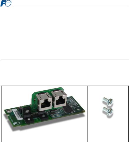
Check the enclosed items. Confirm that the correct quantity of each item was received, and that no damage occurred during shipment.
•OPC-G1-ETH interface board (see Figure 1).
•Two M3 x 6mm mounting screws (see Figure 2).
Figure 2: Qty. 2 M3 x 6mm
Mounting Screws
Figure 1: OPC-G1-ETH Interface Board
9

1.2.2 Component Overview
Figure 3 and Figure 4 provide an overview of the important interface card components.
Port 2 Ethernet jack
Port 1 Ethernet jack
MAC Address
Positioning notch
Module Status and Network Status LEDs
Standoff mounting hole
Figure 3: OPC-G1-ETH Component Overview (Front Side)
Inverter control board connector
USB port
Port 2 Link/Activity and Speed LEDs
Port 1 Link/Activity and Speed LEDs
Standoff mounting hole
Figure 4: OPC-G1-ETH Component Overview (Back Side)
10

Port 1 and Port 2 Ethernet Jacks
Either jack can freely be used star topology networks (with external switch). In linear topologies, a series of OPC-G1-ETH cards can be connected together by daisy-chaining one of the ports to the next inverter in line.
MAC Address
Barcode sticker that indicates the card’s unique Ethernet MAC Address. The MAC Address can be used to identify specific cards discovered with the Fuji Finder application (refer to section 4.3).
Positioning Notch
Aligns with the positioning key on the inverter chassis to ensure that the interface card is installed into the correct communication port (refer to section 2.2).
Module Status and Network Status LEDs
These LEDs indicate the current status of the interface card and protocols in use. Refer to section 1.3.
Standoff Mounting Holes
The provided M3 x 6mm screw are inserted here to secure the card to the standoffs located on the inverter’s control board. Refer to section 2.2.
Inverter Control Board Connector
Attaches to the “A-port” on the inverter’s control board.
USB Port
USB 2.0 port with mini-B connector. Used to access the card via the Fuji Finder program (refer to section 4.5) and as a USB flash drive (refer to section 7.1).
Ethernet Link/Activity and Speed LEDs
One set of LEDs are provided for each Ethernet port (“P1” for Port 1 and “P2” for Port 2). These LEDs provide insight into the Ethernet network’s status and activity. Refer to section 1.3.
11

1.3 LED Indicators
1.3.1 Network Status LED
•Conforms to the prescribed “network status LED” behavior as dictated in the EtherNet/IP specification, Volume 2, Chapter 9.
1.3.2Module Status LED
•Conforms to the prescribed “module status LED” behavior as dictated in the EtherNet/IP specification, Volume 2, Chapter 9.
•Contact technical support if a blinking red error code is observed. Please take note of the flashing 3- digit error code before contacting technical support.
1.3.3Ethernet Link/Activity LEDs
•The green “LNK/ACT” LEDs (one for each Ethernet port) are lit whenever a viable Ethernet network is connected, and blink when network packets are sent or received on the associated port.
1.3.4Ethernet Speed LEDs
•The amber “SPEED” LEDs (one for each Ethernet port) are lit if the link speed is 100 Mbps, and are off if the link speed is 10 Mbps.
1.4 Environmental Specifications
The interface’s environmental specifications are detailed in Table 1.
|
|
Table 1: Environmental Specifications |
||
|
|
|
|
|
|
Item |
|
|
Specification |
|
|
|
|
|
|
Operating Environment |
|
|
Indoors, less than 1000m above sea level, do not expose to direct |
|
|
|
sunlight or corrosive / explosive gasses |
|
|
|
|
|
|
|
|
|
|
|
|
Operating Temperature |
|
|
-10 +50°C (+14 +122°F) |
|
|
|
|
|
|
Storage Temperature |
|
|
-40 +85°C (-40 +185°F) |
|
|
|
|
|
|
Relative Humidity |
|
|
20% 90% (without condensation) |
|
|
|
|
|
|
Vibration |
|
|
5.9m/s2 (0.6G) or less (10 55Hz) |
|
|
|
|
|
|
Cooling Method |
|
|
Self-cooled |
|
|
|
|
|
|
Communication Speed |
|
|
10/100BaseT auto sensing |
|
|
|
|
|
This device is lead-free / RoHS-compliant.
12

2 INSTALLATION
2.1 Pre-Installation Instructions
•To avoid electrical shock, remove all power from the inverter and wait at least five minutes prior to starting installation. Additionally, confirm that the DC link bus voltage as measured between the P
(+) and N (-) terminals is less than 25 VDC.
•Installation should be performed only by qualified personnel.
•To avoid electrical shock, do not operate the inverter with the front cover or wiring cover removed, as accidental contact with exposed high-voltage terminals and internal components may occur.
•To prevent explosions or similar damage, ensure that all cables are properly connected to the correct terminals, and observe all wiring polarity indicators.
2.2 Installation Procedure
Before installing the interface card, perform all wiring for the main circuit terminals and control circuit terminals.
1.Remove the front cover from the inverter to expose the control printed circuit board (control PCB). As shown in Figure 5, there are three option connection ports (A-port, B-port and C-port). The OPC-G1-ETH card is mechanically keyed for, and can only be installed into, the A-port (bottommost) position.
To remove the front cover, refer to the FRENIC-MEGA Instruction Manual, Chapter 2, Section 2.3. The keypad enclosure must also be opened on 30kW and larger inverters.
Figure 5: Option Port Locations on 0.4 kW Inverter
13

2.Rest the left-hand side of the interface card on the control PCB’s A-port mounting support. Align
the positioning notch on the interface card with the A-port positioning key, and then slide the interface card to the left to engage the key into the notch. Refer to step in Figure 6.
3.Rotate the right-hand side of the interface card downward to engage connector CN1 (on the back
of the interface card) into the A-port connector (CN4) on the inverter’s control PCB. Ensure that the connectors are fully engaged. Refer to step in Figure 6.
To ensure that the interface card is fully aligned and seated into the communication
port, be sure to perform steps and in the proper order. Failure to do so may lead to insufficient connector insertion and result in contact failure.

Positioning Key
Figure 6: Mounting the Interface Card
4.Install the two M3 x 6mm screws included with the kit into the standoff mounting holes located at the upper-left and lower-right hand corners of the interface card. Tighten the screws to secure the interface card to the control board PCB. Refer to Figure 7.
Figure 7: Interface Card Mounting Completed
5.Connect the network cables as necessary. Insert the Ethernet cables into the Ethernet jacks, making sure that they are fully seated. Ensure that the cables are routed in such a way that they will not be pinched and are not located near any power-carrying wiring, such as the inverter’s input power or motor wires.
6.Reinstall all covers removed in step 1. Take a moment to confirm that the Ethernet cables are not being pinched and are not routed near any power-carrying wiring.
For reinstallation instructions, refer to the FRENIC-MEGA Instruction Manual, Chapter 2, Section 2.3. The keypad enclosure must also be closed on 30kW and larger inverters.
14

3 INVERTER FUNCTION CODE SETTINGS
Depending on the desired operation of the overall application, the inverter function codes listed in Table 2 are important for proper operation of the end-to-end communication system. Although there may be many other function codes that will require configuration for your specific application, it is important to understand the manner in which the following function codes will impact successful control of the inverter.
For further details regarding these function codes, please refer to the FRENIC-Mega
Instruction Manual (INR-SI47-1457-E), Chapter 5 "FUNCTION CODES", FRENIC-Mega User’s Manual, “y codes: Link Functions”, and RS-485 Communication User's Manual (MEH448), Chapter 5, Section 5.2 "Data Formats."
Table 2: Function Code Settings Overview
Code |
Name |
|
Setting |
|
|
Default |
|
|
Range |
|
|
Value |
|
||
|
|
|
|
|
|
||
|
|
|
|
|
|
|
|
Y98 |
Bus Link Function (Mode Selection) |
|
0 to 3 |
0 |
|
||
|
|
|
|
|
|
|
|
3.1 Inverter Control-Related Settings
The following function codes relate to whether or not the inverter is to be controlled (command word and/or frequency command) from the network, or whether the inverter will be locally-controlled (and therefore only monitored and/or configured via the network.)
Bus Link Function (Mode Selection) (y98)
If the inverter is to be controlled from the network, then set the value of y98 to 3 (fieldbus option). A setting of 3 for y98 may also be appropriate even if H30 is configured for an alternate (local) control scheme.
When the inverter is controlled from the network, a selection of reference commands (S?? function codes) are available for controlling the inverter’s speed. If multiple reference commands are being modified from the network, then the interface card invokes a hierarchy to determine which reference is to be passed to the inverter as its main reference command.
The S?? function code hierarchy is as follows, listed from highest to lowest priority:
•S01 (frequency reference / per-unit)
•S05 (frequency reference / Hz)
•S19 (speed command)
•S02 (torque command)
•S03 (torque current command)
•S13 (PID command)
The highest-priority S?? function code with a non-zero value will be used as the inverter’s main reference command.
15

3.2 Inverter Reaction to Network Timeout Conditions
Function codes o27 and o28 specify the inverter’s reaction when a network timeout occurs. Table 3 lists the settings for o27 and o28.
Table 3: Inverter Reaction to Network Timeout Conditions (Function Codes o27 and o28)
o27 Value |
o28 Value |
Inverter reaction when a timeout occurs |
Remarks |
|
0, |
--- |
Immediately coast to a stop and trip er5. |
|
|
4 to 9 |
|
|||
|
|
|
||
1 |
0.0s to 60.0s |
After the time specified by o28, coast to a stop |
|
|
and trip er5. |
|
|||
|
|
If the communications link is restored within the |
|
|
2 |
0.0s to 60.0s |
time specified by o28, ignore the |
|
|
|
|
communications error. After the timeout, coast |
|
|
|
|
to a stop and trip er5. |
|
|
3, |
--- |
Maintain present operation, ignoring the |
|
|
13 to 15 |
communications error (no er5 trip). |
|
||
|
|
|||
10 |
--- |
Immediately decelerate to a stop. Trip er5 |
Inverter function code |
|
F08 specifies the |
||||
after stopping. |
||||
|
|
deceleration time. |
||
|
|
|
||
|
|
|
|
|
11 |
0.0s to 60.0s |
After the time specified by o28, decelerate to a |
Same as above. |
|
stop. Trip er5 after stopping. |
||||
|
|
If the communications link is restored within the |
|
|
12 |
0.0s to 60.0s |
time specified by o28, ignore the |
Same as above. |
|
communications error. After the timeout, |
||||
|
|
decelerate to a stop and trip er5. |
|
16

4 FUJI FINDER APPLICATION
The Fuji Finder application is a Microsoft Windows® -based PC program which provides several configuration and maintenance utilities for the OPC-G1-ETH, such as Ethernet-based IP address configuration and USB-based firmware updating. The Fuji finder installation files are located on the CDROM included with the OPC-G1-ETH kit.
4.1 Installation
The Fuji Finder setup will install all required files and USB device drivers. Note that the Fuji Finder program should be installed before connecting any OPC-G1-ETH devices to the computer’s USB port, as the program contains product-specific USB drivers that must be installed on the computer prior to initial connection of the target device.
Launch the install executable
To start the installation of the Fuji Finder application, run the “SETUP” executable located on the CDROM included with the OPC-G1-ETH kit.
Review the installation message (Figure 8) and click “Next”
Figure 8: Installer Welcome Screen
17

Select the install folder
Select the folder where you want the Fuji Finder to be installed (Figure 9).
Figure 9: Installation Folder Selection Screen Confirm and click “Next” to start installation (Figure 10)
Figure 10: Installation Confirmation Screen
18

Wait while the configuration utility is being installed (Figure 11)
Figure 11: Installation Progress Screen
If you are prompted by the operating system during this stage that it can’t verify the publisher of this driver software, choose “Install this driver software anyway”.
Installation complete
Click “Close“ to exit the installer (Figure 12).
Figure 12: Installation Complete Screen
19
4.2 USB Driver Installation
By using a USB mini-B cable, an OPC-G1-ETH card can be connected to the PC, powered, and updated. This section explains setting up the PC to work with an OPC-G1-ETH.
After the Fuji Finder application is installed, the PC will be able to automatically install the appropriate USB driver when an OPC-G1-ETH card is connected via USB. Note that the Fuji Finder application must be installed prior to connecting an OPC-G1-ETH card to the PC: the PC will not be able to automatically install the USB driver until the Fuji Finder installation is complete.
The following sections will provide an overview of the USB driver installation procedure for Windows XP and Windows 7. Other versions of Windows may have slightly different procedures.
4.2.1 Windows XP
If this is the first time connecting the card to your computer, the operating system will prompt you to install the card’s USB driver.
Found New Hardware Wizard
Select “No, not this time“ when prompted for Windows to connect to Windows Update (Figure 13).
Figure 13: Found New Hardware Screen
20

Select Recommended Install
Accept the default action (Figure 14).
Figure 14: Select Install Type Screen The Wizard Will Search for the Appropriate Driver (Figure 15)
Figure 15: Searching for Driver
21

Device Installation Complete
The device driver has been successfully installed (Figure 16). Click Finish to close the wizard.
Figure 16: USB Driver Installation Complete Screen
Because the OPC-G1-ETH interface card is a USB composite device (which is to say that it presents multiple virtual representations to the computer), after the vendor-specific USB driver has been installed as detailed above, Windows will then additionally identify the device as a USB mass storage device (also known as a “flash drive” or “removable disk”), and automatically install the default Windows USB mass storage device drivers. Once this is completed, the operating system may automatically pop up a Windows Explorer window showing the file contents of the OPC-G1-ETH’s on-board filesystem (Figure 17). This window can be closed at this time if desired.
Figure 17: Windows Explorer Removable Disk View
22

4.2.2 Windows 7
Enhancements in Windows 7 automate the installation of USB drivers to such a degree that no user interaction should be required. When the OPC-G1-ETH card is initially connected to the computer, the operating system should automatically locate and install the appropriate USB driver. Once completed, the operating system may display a dialog box similar to that shown in Figure 18.
Figure 18: Windows 7 USB Driver Successful Installation
Because the OPC-G1-ETH interface card is a USB composite device (which is to say that it presents multiple virtual representations to the computer), after the vendor-specific USB driver has been installed as detailed above, Windows will then additionally identify the device as a USB mass storage device (also known as a “flash drive” or “removable disk”), and automatically install the default Windows USB mass storage device drivers. Once this is completed, the operating system may automatically pop up an AutoPlay window showing the options available for the removable disk (Figure 19). This window can be closed at this time if desired.
Figure 19: Windows 7 AutoPlay
23

4.3 Overview
The “Fuji Finder” application is a simple Windows PC program, which when executed discovers all OPC- G1-ETH cards on the current Ethernet subnet, regardless of whether or not their network parameters are currently compatible with the subnet upon which they reside. The utility is also used to update firmware.
These functions are accessed via two tabs available on the Finder application main program window (refer to Figure 20 and Figure 21.)
Figure 20: Fuji Finder Ethernet tab
Figure 21: Fuji Finder USB tab
24

4.4 Ethernet Tab
All devices discovered on the current Ethernet subnet can be organized in ascending or descending order by clicking on the desired sort header (Product, IP Address, MAC Address or Application Firmware). The buttons on the left side of the window perform the following actions:
Update IP Settings: Allows configuration of the static IP parameters. Refer to section 4.6 for more information.
Open Web: Opens a web browser page of the selected device. Refer to section 5.
Reboot Device: Reboots the currently-selected interface card. The Finder application will then automatically rescan the network.
Refresh List: Causes the Finder application to rescan the network.
Note that in order for the Finder application to discover devices on the Ethernet subnet, certain UDP traffic must be allowed in and out of the computer, and firewall applications (such as Windows Firewall) are often configured to block such traffic by default. If the Finder is unable to discover any devices on the current subnet, be sure to check the computer’s firewall settings during troubleshooting, and add an exception to the firewall configuration if necessary. The Finder application uses UDP port 4334.
4.5 USB Tab
All devices connected to the computer via USB can be organized in ascending or descending order by clicking on the desired sort header (Product, Manufacturer or Application Firmware). The buttons on the left side of the window perform the following actions:
Device Info: Provides general device info.
Update Firmware: Update the firmware. Refer to section 7.3.
View Files: Provides access to the on-board file system with Windows Explorer. Refer to section 7.1.
Reboot Device: Reboots the interface card. The Finder will automatically detect the card once it has completed rebooting.
4.6 Configuring the IP Address
Before you can access the interface card from your web browser or begin using it as a part of your automation network, you must assign it an IP address that is appropriate for the subnet on which the card will reside. The interface card comes from the factory configured with a static IP address of 192.168.16.102. Modifying the IP address can be accomplished with the Finder application via the following procedure:
1.Connect the interface card to the same Ethernet subnet on which the computer resides and apply power to the inverter in which it is installed.
2.Start the Fuji Finder application.
3.The Finder application will scan the Ethernet network for Fuji devices and then display each device’s information on the “Ethernet” tab. Refer to Figure 20. If multiple devices are discovered, identify the targeted device via its unique MAC address (printed on a barcode label on the lefthand side of the interface card).
4.To change the IP address, select the device in the list of detected devices.
5.Configure the IP Address Settings with the desired IP Address, Subnet Mask and Default Gateway in the appropriate boxes. Click the Update IP Settings button to apply the changes.
6.A popup dialog box will prompt you to reboot. Click Yes. The dialog box will automatically close when the device is done rebooting.
7.The Finder application will automatically rescan the network. Confirm that the new IP address has been accepted by the device.
25

5 EMBEDDED WEB SERVER
5.1 Overview
The interface contains an embedded web server (also known as an HTTP server), which allows users to access the inverter’s internal data in a graphical manner with web browsers such as Microsoft Internet Explorer or Mozilla Firefox. In this way, the inverter can be monitored, configured and controlled from across the room or from across the globe.
In order to view the interface’s factory-default web page, the free Adobe (formerly Macromedia) Flash Player browser plug-in is required. If the plug-in is not already installed on your computer, then your browser will automatically be redirected to the appropriate Adobe download web site when you initially attempt to access the interface’s web page. Alternatively, the plug-in can be downloaded directly from http://www.adobe.com. Always ensure that you have the latest version of the Flash Player installed: if some aspect of the web page does not appear to be displayed properly, installing the latest Flash Player update usually resolves the problem.
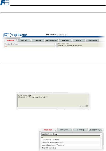
To access an interface’s embedded web server, either use the finder application (refer to section 4) and select the “Open Web” button when the target unit is highlighted, or just directly enter the target unit’s IP address into the address (URL) field of your web browser. Refer to Figure 22 for a representative screenshot of the web server interface.
Figure 22: Embedded Web Server
In order to access the web server and view the function code values, destination TCP ports 80 and 2000 must be accessible from the client computer. If an “XML socket connection failed” error message is displayed in the information window, and no function code values are shown, this is typically indicative of port 2000 being blocked by a firewall or Ethernet router situated between the client computer and the interface card.
26
5.2 Page Select Tabs
The web interface is subdivided into several different “tabs” of associated information, much the same as how folders in a filing cabinet are arranged. Refer to Figure 23. To change tabs, just click on the tab you wish to view. The title of the currently-selected tab is red. Note that because different protocols are supported by the interface with different firmware images, not all tabs may be accessible with the firmware image currently loaded. The titles of tabs that are not accessible are grayed-out, and clicking them has no effect.
Figure 23: Page Select Tabs
5.3 Monitor Tab
5.3.1 Information Window
Figure 24 shows the Information Window, which is located in the upper-right hand corner of the monitor tab. This window displays various informational messages regarding the status of the interface card or web browser session. There is also an “activity” indicator located in the lower-right hand corner of the Information Window, which blinks periodically to show the status of data communication between the web browser and the interface card. If you do not observe the activity indicator blink at all for several seconds or more, it is possible that the web browser may have lost contact to the web server due to an inverter power cycle or a network problem: to reestablish communications, select “refresh” on your web browser.
Figure 24: Monitor Tab Information Window
5.3.2 Function Code Group Selection List
The Function Code Group Selection List is located in the upper-left hand corner of the Monitor Tab. Refer to Figure 25. Individual groups can be selected by clicking on the group name. Multiple groups may also be selected by holding down the CTRL key while clicking on the group names, or a range of groups can be selected by first selecting the starting group,
and then holding down the SHIFT key while selecting the last group in the range. When a function code group is selected, the function codes contained in that group are displayed in the Function Code List (refer to section 5.3.3). The following function code groups are available:
All: All function codes/registers are available.
Fundamental Functions: F function codes are available.
Extension Terminal Functions: E function codes are available.
27

Control Functions of Frequency: C function codes are available.
Motor 1 Parameters: P function codes are available.
Motor 2 Parameters: A function codes are available.
Motor 3 Parameters: b function codes are available.
Motor 4 Parameters: r function codes are available.
High Performance Functions: H function codes are available.
Application Functions 1: J function codes are available.
Application Functions 2: d function codes are available.
Link Functions: y function codes are available.
Command Data: S function codes are available.
Monitor Data 1: M function codes are available.
Monitor Data 2: W function codes are available.
Alarm Data 1: X function codes are available.
Alarm Data 2: Z function codes are available.
Operational Functions: o function codes are available.
5.3.3 Function Code List
The bottom half of the Monitor tab contains the function code list (refer to Figure 26). The function codes that are displayed in the list at any given time depend on the function code groups that are currently selected (refer to section 5.3.2), as well as whether or not any filters have been applied (refer to section 5.3.4).
The first column of the Function Code List shows the inverter function code designation that is normally used when accessing a given function code via the inverter’s keypad. Note that this column is for user convenience and inverter user’s manual cross-reference.
The second column of the Function Code List shows the register number for the corresponding function code. Certain protocols require the use of a register number to access the function code (refer to section 6). The third column contains the function code descriptions, which are used by the filter function. The last column performs two functions: it displays the current value of the function code, and (for writable function codes) also allows changing the function code’s value by clicking on the number in the value column and entering the new value.
Figure 26: Function Code List
28

Some items to keep in mind when interacting with the Function Code List are:
•When entering new function code values, be sure that the number being entered is appropriate for the currently-selected radix (refer to section 5.3.5): for example, an entered value of “1000” in hexadecimal is equal to 4096 in decimal.
•If desired, the column widths can be changed by dragging the vertical bars that separate the header row’s cells to a different position.
•If you begin changing a function code value and then decide to abandon the change, pressing the ESC key on your keyboard will abandon the change and redisplay the current function code value.
•When editing a function code value, clicking someplace off the entry cell is equivalent to hitting the ENTER key.
5.3.4Function Code List Filter
A filter function provides Function Code List search |
|
capabilities. To use the filter function, simply type a |
|
word or portion of a word into the filter entry box and |
|
then click the “filter” button. Refer to Figure 27. |
Figure 27: Function Code List Filter |
|
The filter will then display only those function codes
currently available in the Function Code List that satisfy the search criteria. For example, to find all monitor data 1 function codes that contain some derivative of the word “volt” (such as “voltage” or “volts”), select the “Monitor Data 1” group, enter “volt” in the filter entry box, and then click the “filter” button.
Once a filter has been entered, it will continue to be applied to all information normally displayed in the Function Code List for as long as the filter term is left in the filter entry box. Continuing the previous example where we filtered on the root term “volt” in the monitor data 1 group, we can then easily apply this filter to all available function codes simply by selecting the “All” function code group. The Function Code List will now display all command, monitor, configuration etc. function codes that contain the root term “volt”.
To remove the filter, delete any characters contained in the filter entry box and then click the “filter” button.
5.3.5 Radix Selection
Figure 28 shows the radix selection buttons. These selection buttons allow changing the Function Code List “value” column data display and entry radix between decimal and hexadecimal formats.
When “DEC” is selected, the “value” column heading will be “Value (Decimal)”, current function code values will be displayed in decimal,
and values to be written to function codes must be entered in decimal format. For example, to change the inverter’s frequency command to 40.00Hz, enter the decimal value 4000.
Similarly, when “HEX” is selected, the “value” column heading will be “Value (Hexadecimal)”, current function code values will be displayed in hexadecimal, and values to be written to function codes must be entered in hexadecimal format. For example, to turn on bit #10 in the inverter’s operation command word, enter the hexadecimal number 0400.
29
Loading...