


 Loading...
MEH 533

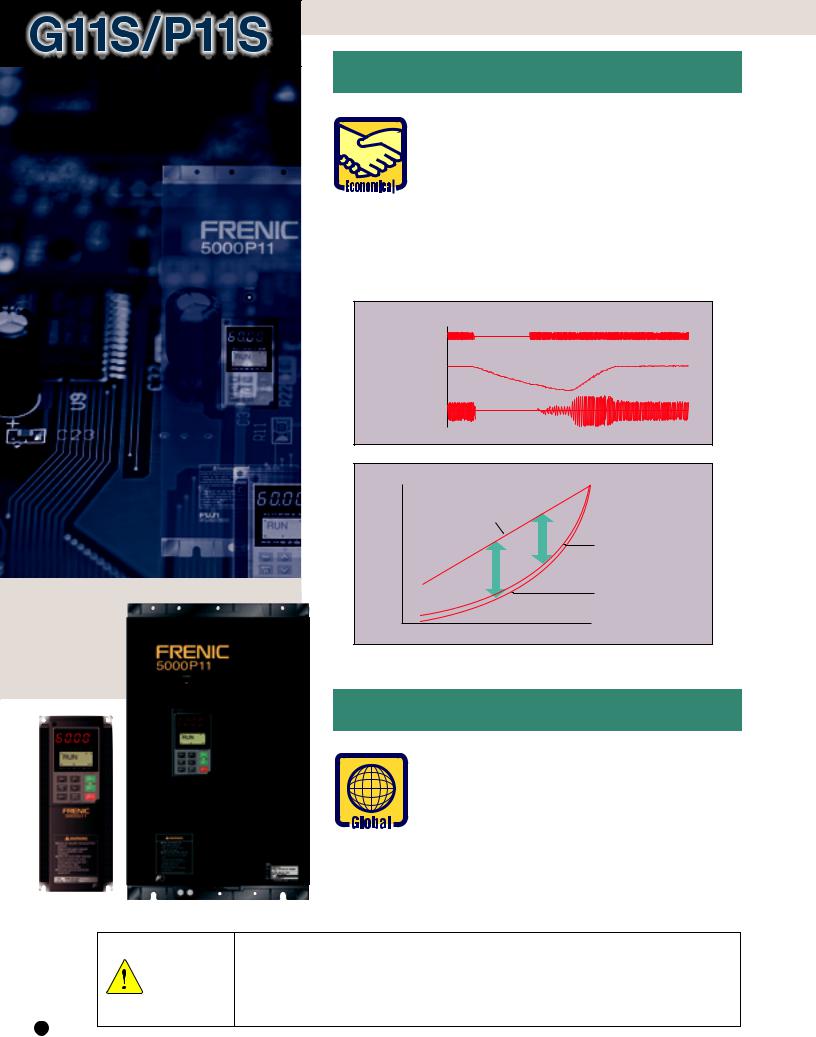
Ideal combination of power and multiple-function. Dynamic torque-vector control promises
optimum motor control under any operating conditions.
1.Dynamic torque-vector control
Dynamic torque-vector control system performs high-speed calculation to determine the required motor power for the load status. Our key technology is optimal control of voltage and current vectors for maximum output torque.
●A high starting torque of 200% at 0.5Hz.*
* 180% for 40HP or larger models.
●Achieves smooth acceleration/ deceleration in the shortest time for the load condition.
●Using a high-speed CPU quickly responds to an abrupt load change, detects the regenerated power to control the deceleration time. This automatic decerelation function greatly reduces the inverter tripping.
●Feedback control with PG
Enables the inverter to execute “vector control with PG” by adding an optional PG feedback card to obtain higher perfor-
mance.
• Speed control range : 1:1200
• Speed control accuracy :  0.02%
0.02%
• Speed control response : 40Hz
2. Reduced motor wow at low speed
● Motor wow at low speed (1Hz) reduced to less than 1/2 of that achieved by conventional inverters, with the dynamic torque-vector control system, in combination with the Fuji’s unique digital AVR.
Torque characteristics with Dynamic torque-vector control (Sample: 5HP)
|
300 |
|
|
|
|
200 |
|
|
|
[%] |
100 |
|
|
|
torque |
0 |
|
|
|
1000 |
2000 |
|||
Output |
|
|||
100 |
|
Motor speed |
||
|
|
[r/min] |
||
|
|
|
||
|
200 |
|
|
|
|
300 |
|
|
PG Vector Control |
Step load response (Sample : 5HP) |
|
|
||
|
100 |
|
Actual torque [%] |
0 |
|
|
|
|
|
100 |
|
Torque reference [%] |
0 |
|
|
|
|
Motor speed [r/min] |
500 |
|
|
|
|
|
400 |
|
|
20 |
|
Motor current [A] |
0 |
|
Time |
320ms |
Wow characterisics(Sample: 5HP) |
|
Conventional Fuji inverter |
|
0 |
14 r/min |
FRN-G11S |
|
0 |
5 r/min |
Time |
500ms |
2

3. New on-line tuning system
● On-line tuning to continuously check for variation of motor characteristics during running for high-precision speed control.
● This tuning function also available for a second motor, which allows high-precision driving of the second motor by changeover operation between two motors.
Motor temperature vs speed variation (Sample: 5HP)
|
|
70°C |
|
|
(158°F) |
|
|
F)]° |
Motor speed [r/min] |
30°C(86°F) |
Temperature [°C( |
With on-line tuning |
||
|
||
|
Without on-line tuning |
|
0 |
Time [min] |
8 0 |
4.Environment-friendly features
●Provided with low-noise control power
supply systems which minimize noise interference on peripheral devices such as sensors.
●Equipped with terminals for connecting DC REACTOR that can suppress harmonics.
●Complied with EMC Directive (Emission) when connected to optional EMCcompliance filter.
3
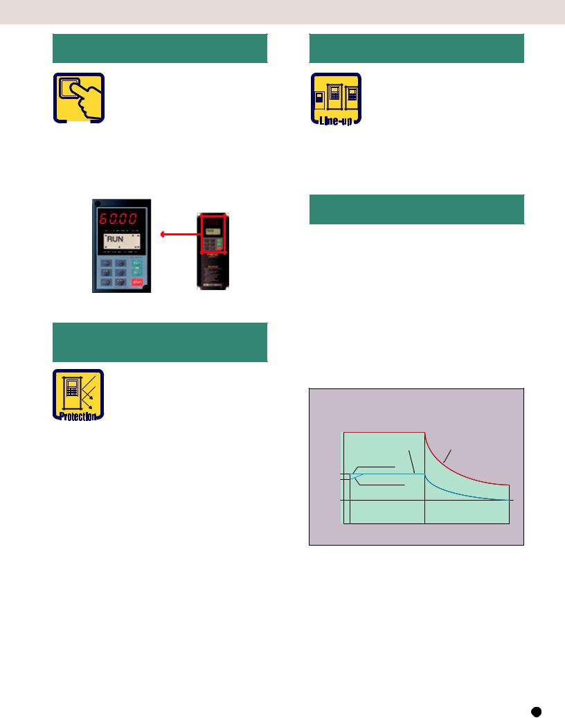
5. Advanced, convenient functions
● 16-step speed with timer control, rotating motor pick-up control for conveyance machinery
● Automatic energy-saving operation, PID control, cooling fan on/off control, line/
inverter changeover operation for fans and pumps
●Rotating motor pick-up control:
Restarts motor without any shocks, by detecting motor speed where motor is coasting after momentary power failure occurs.
●Automatic energy-saving operation function: Minimizes inverter and motor loss at light load.
Rotating motor pick-up control characteristics (Sample:5HP)
Power source
Motor speed [r/min]
Output current [A]
Time 
Energy saving effect
100 |
|
|
|
[%] |
Damper control |
|
|
power |
|
Inverter control |
|
Energy |
(V / f control) |
||
Required |
|||
saved |
|
||
|
Inverter control |
||
|
(Automatic energy-saving |
||
|
|
control) |
|
0 |
Flow rate [%] |
100 |
|
|
6. Global products, communication
● Conforms to major world safety standards: UL, cUL, TÜV (up to 30HP), EN (CE marking)
● Equipped with RS-485 interface as standard.
● Connection to field bus: PROFIBUS-DP, Interbus- S, DeviceNet, Modbus Plus (Option)
● Universal DI/DO : Monitors digital I/O signal status and transmits to a host controller, helping to simplify factory automation.
|
1. |
Use the contents of this catalog only for selecting product types and models. When using a product, read the Instruction |
|
|
Manual beforehand to use the product correctly. |
Safety |
2. |
Products introduced in this catalog have not been designed or manufactured for such applications in a system or equipment |
|
that will affect human bodies or lives. Customers, who want to use the products introduced in this catalog for special systems |
|
Precautions |
|
or devices such as for atomic-energy control, aerospace use, medical use, and traffic control, are requested to consult the |
|
|
Fuji's Sales Division. Customers are requested to prepare safety measures when they apply the products introduced in this |
|
|
catalog to such systems or facilities that will affect human lives or cause severe damage to property if the products become |
|
|
faulty. |
4
7.Intelligent Keypad panel
●Copy function: Easily copies function codes and data to other inverters.
●Six languages (English, French,

 German, Italian, Spanish, and Japanese) are available as standard.
●Jogging (inching) operation from the Keypad or external signal
●Remote operation using optional extension cable (CBIII-10R-¤¤¤)
8.Protective functions, Maintenance
Protection
● Motors with various characteristics can be used by setting thermal time constant for the electronic thermal overload protection.
●Input phase loss protective function protects the inverter from damage caused by disconnection of power supply lines.
●Motor is protected with a PTC thermistor.
●Input terminals for auxiliary control power supply (2HP or larger models) : Alarm signal output will be held even if main circuit power supply has shut down.
Excellent maintainability
The items below can be monitored on the Keypad panel and making it easy to analyze the cause of trip and to take preventive measures.
●Input/output terminals check
●Life expectancy of main-circuit capacitors
●Inverter on-load factor
●Accumlated operation time
●Inverter operating condition (output current, heat sink temperature, input power, etc.)
●Detailed data on trip cause
G11S/P11S
9. Extensive product line
● Two series are available: G11S series ranging from 1/4 to 600HP for general industrial machines and P11S series ranging from 7.5 to 800HP for fans and pumps.
●Totally-enclosed casing (NEMA1) (up to 30HP as standard).
●Optional NEMA1 enclosure available for 40HP or larger models.
10. Other useful functions
●Side-by-side mounting (up to 30HP) saves space when inverters are installed in a panel.
●The uniform height (10.24inch(260mm)) of products (up to 10HP) makes it easy to design panels.
●User-definable control terminals: Digital input (9 points), transistor output (4points), and relay contact output (1point).
●Active drive feature: Performs prolonged acceleration at reduced torque, monitoring the load status to prevent tripping.
●Stall prevention function is provided as standard. Active or inactive can be also selected.
Torque characteristics with Dynamic torque-vector control
100% of output torque refers to the rated torque of the motor driven at 60Hz.
|
200 |
|
|
|
|
|
|
|
Continuous operation torque |
|
Short-time operation torque |
||||
|
|
|
|||||
[%] |
|
(with dynamic torque-vector control) |
(with dynamic torque-vector control) |
||||
|
|
|
|
|
|
|
|
torque |
|
|
up to 10HP |
|
|
||
100 |
|
|
|
15 to 30HP |
|
|
|
|
|
|
|
|
|||
Output |
90 |
|
|
|
|
|
|
50 |
|
|
|
|
|
|
|
|
|
|
|
|
|
|
|
|
|
|
|
|
|
|
|
|
|
1 6 |
15 20 |
60 |
120 |
||
|
|
|
|
|
Output frequency [Hz] |
||
*The above graph shows an example of torque characteristics when combining FRENIC5000G11S (up to 30HP at dynamic torque-vector control) with Fuji standard three-phase motor (8-type series, 4 poles). Continuous operation torque is for limits of allowable load torque for using the motor within the allowable temperature range and is not for motor output torque.
The motor output torque is shown by the short-time
operation torque.
5

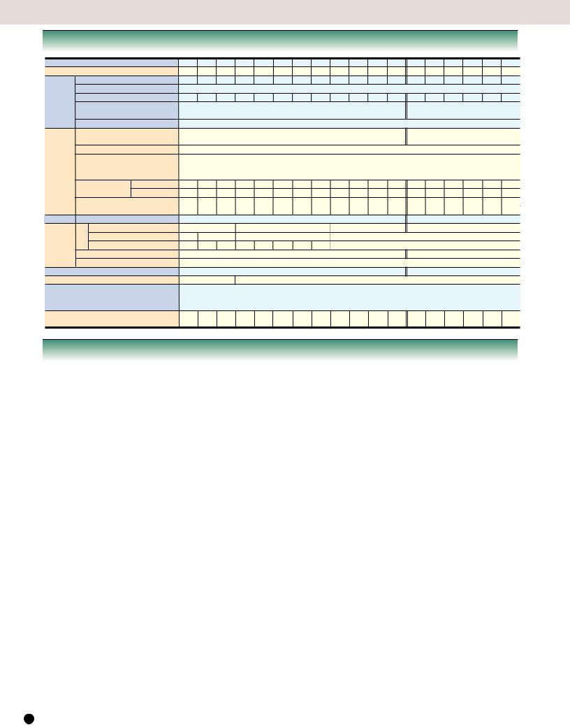
Variation
Easy to apply to customer systems.Aconsistent design concept in all models from 1/4HP to 800HP.
|
|
|
|
|
|
|
|
|
|
|
|
|
|
|
|
|
FRENIC5000G11S series |
|
|
|
|
|
|
||||
|
|
|
|
|
|
FRENIC5000P11S series |
|
||||||
|
|
|
for general industrial machines |
|
|
|
for fans and pumps (variable torque loads) |
|
|
||||
|
|
|
|
|
|
|
|
|
|
|
|
|
|
|
|
|
|
|
|
|
|
|
|
|
|
|
|
|
Nominal |
|
|
|
|
|
|
|
|
|
|
|
|
|
applied |
|
230V |
|
460V |
|
|
230V |
|
460V |
|
|
|
|
motors [HP] |
|
|
|
|
|
|
|
|
|
|
|
|
|
|
|
|
|
|
|
|
|
|
|
|
|
|
|
1/4 |
|
FRNF25G11S-2UX |
|
|
|
|
|
|
|
|
|
|
1/2 |
|
FRNF50G11S-2UX |
|
FRNF50G11S-4UX |
|
|
|
|
|
|
|
||
|
1 |
|
FRN001G11S-2UX |
|
FRN001G11S-4UX |
|
|
|
|
|
|
|
|
2 |
|
FRN002G11S-2UX |
|
FRN002G11S-4UX |
|
|
|
|
|
|
|
||
|
3 |
|
FRN003G11S-2UX |
|
FRN003G11S-4UX |
|
|
|
|
|
|
|
|
5 |
|
FRN005G11S-2UX |
|
FRN005G11S-4UX |
|
|
|
|
|
|
|
||
|
7.5 |
|
FRN007G11S-2UX |
|
FRN007G11S-4UX |
|
|
FRN007P11S-2UX |
|
FRN007P11S-4UX |
|
|
|
10 |
|
FRN010G11S-2UX |
|
FRN010G11S-4UX |
|
|
FRN010P11S-2UX |
|
FRN010P11S-4UX |
|
|
||
|
15 |
|
FRN015G11S-2UX |
|
FRN015G11S-4UX |
|
|
FRN015P11S-2UX |
|
FRN015P11S-4UX |
|
|
|
20 |
|
FRN020G11S-2UX |
|
FRN020G11S-4UX |
|
|
FRN020P11S-2UX |
|
FRN020P11S-4UX |
|
|
||
|
25 |
|
FRN025G11S-2UX |
|
FRN025G11S-4UX |
|
|
FRN025P11S-2UX |
|
FRN025P11S-4UX |
|
|
|
30 |
|
FRN030G11S-2UX |
|
FRN030G11S-4UX |
|
|
FRN030P11S-2UX |
|
FRN030P11S-4UX |
|
|
||
|
40 |
|
FRN040G11S-2UX |
|
FRN040G11S-4UX |
|
|
FRN040P11S-2UX |
|
FRN040P11S-4UX |
|
|
|
50 |
|
FRN050G11S-2UX |
|
FRN050G11S-4UX |
|
|
FRN050P11S-2UX |
|
FRN050P11S-4UX |
|
|
||
|
60 |
|
FRN060G11S-2UX |
|
FRN060G11S-4UX |
|
|
FRN060P11S-2UX |
|
FRN060P11S-4UX |
|
|
|
75 |
|
FRN075G11S-2UX |
|
FRN075G11S-4UX |
|
|
FRN075P11S-2UX |
|
FRN075P11S-4UX |
|
|
||
|
100 |
|
FRN100G11S-2UX |
|
FRN100G11S-4UX |
|
|
FRN100P11S-2UX |
|
FRN100P11S-4UX |
|
|
|
125 |
|
FRN125G11S-2UX |
|
FRN125G11S-4UX |
|
|
FRN125P11S-2UX |
|
FRN125P11S-4UX |
|
|
||
|
150 |
|
|
|
FRN150G11S-4UX |
|
|
FRN150P11S-2UX |
|
FRN150P11S-4UX |
|
|
|
200 |
|
|
|
FRN200G11S-4UX |
|
|
|
|
FRN200P11S-4UX |
|
|
||
|
250 |
|
|
|
FRN250G11S-4UX |
|
|
|
|
FRN250P11S-4UX |
|
|
|
300 |
|
|
|
FRN300G11S-4UX |
|
|
|
|
FRN300P11S-4UX |
|
|
||
|
350 |
|
|
|
FRN350G11S-4UX |
|
|
|
|
FRN350P11S-4UX |
|
|
|
400 |
|
|
|
FRN400G11S-4UX |
|
|
|
|
FRN400P11S-4UX |
|
|
||
|
450 |
|
|
|
FRN450G11S-4UX |
|
|
|
|
FRN450P11S-4UX |
|
|
|
500 |
|
|
|
FRN500G11S-4UX |
|
|
|
|
FRN500P11S-4UX |
|
|
||
|
600 |
|
|
|
FRN600G11S-4UX |
|
|
|
|
FRN600P11S-4UX |
|
|
|
700 |
|
|
|
|
|
|
|
|
|
FRN700P11S-4UX |
|
|
|
|
800 |
|
|
|
|
|
|
|
|
|
FRN800P11S-4UX |
|
|
|
|
|
|
|
|
|
|
|
|
|
|
|
|
FRENIC 5000G1 industrial plant
Fans
●Air-conditioning system (for factory, building, office, hospital, clean room, shop, and cattle barn)
●Dryer
●Boiler fan
●Fans for controlling furnace temperature
●Roof fans controlled as a group
●Refrigerator
●Compressor
●Built-in blower in a filmmanufacturing machine
●Cooling-tower fans
●Ventilating fans
●Air-conditioning equipment
 How to read the model number
Code Application range
GGeneral industrial machines
Code |
Series name |
|
P Fans and pumps |
Code |
Protective structure |
|
|
|
||||||||||||||||||||||||||
FRN |
FRENIC 5000 series |
|
|
|
|
|
|
|
|
|
|
|
|
|
|
S |
Standard |
|
|
|
|
Code |
|
Version |
|
Food processing machines |
||||||||
|
|
|
|
|
|
|
|
|
|
|
|
|
|
|
|
|
|
|
||||||||||||||||
|
|
|
|
|
|
|
|
|
|
|
|
|
|
|
|
|
|
|
|
|
|
|
|
|
|
|
|
|
||||||
|
|
|
|
|
|
|
|
|
|
|
|
|
|
|
|
|
|
|
|
|
|
|
|
|
|
|
|
UX |
|
|
UX |
|||
|
|
|
|
|
|
|
|
|
|
|
|
|
|
|
|
|
|
|
|
|
|
|
|
|
|
|
|
|
|
|
|
|
|
● Food mixing machine |
|
|
|
|
|
FRN F50 G 11 S - 4 UX |
|
|
|||||||||||||||||||||||||||
|
|
|
|
|
|
|
● Grain milling machine |
|||||||||||||||||||||||||||
|
|
|
|
|
|
|
|
|
|
|
|
|
|
|
|
|
|
|
|
|
|
|
|
|
|
|
|
|
|
|
|
|
|
● Food slicer |
|
|
|
|
|
|
|
|
|
|
|
|
|
|
|
|
|
|
|
|
|
|
|
|
|
|
|
|
|
|
|
|
|
|
(bread, cake, noodles) |
|
|
|
|
|
|
|
|
|
|
|
|
|
|
|
|
|
|
|
|
|
|
|
|
|
|
|
|
|
|
|
|
|
|
|
|
Code |
|
Nominal applied motors [HP] |
|
|
|
|
|
|
|
|
|
|
|
|
|
|
|
Code |
|
Input power source |
● Tea making machine |
||||||||||||
|
|
|
|
|
|
|
|
|
|
|
|
|
|
|
|
|
|
|||||||||||||||||
|
|
|
|
|
|
|
|
|
|
|
|
|
|
|
● Rice cleaning machine |
|||||||||||||||||||
|
F25 |
|
1/4HP |
|
|
|
|
|
Code |
Developed inverter series |
2 |
|
|
Three-phase 230V |
||||||||||||||||||||
|
F50 |
|
1/2HP |
|
|
|
|
|
|
|
|
|
|
|
|
|
|
|
|
|
|
4 |
|
|
Three-phase 460V |
|
||||||||
|
11 |
|
11 series |
|
|
|
|
|
||||||||||||||||||||||||||
001 |
|
1HP |
|
|
|
|
|
|
|
|
|
|
|
|
|
|
|
|
|
|
|
|
|
|
|
|
|
|
|
|
|
|||
002 |
|
2HP |
|
|
|
|
|
|
|
|
|
|
|
|
|
|
|
|
|
|
|
|
|
|
|
|
|
|
|
|
|
|||
|
to |
|
to |
|
|
|
|
|
|
|
|
|
|
|
|
|
|
|
|
|
|
|
|
|
|
|
|
|
|
|
|
|
||
800 |
|
800HP |
|
|
|
|
|
|
|
|
|
|
|
|
|
|
|
|
|
|
|
|
|
|
|
|
|
|
|
|
|
|||
6

G11S/P11S
1S/P11S can be used for almost all and equipment areas.
Machine tools |
Conveyance machinery |
● Grinding machine |
● Crane (traveling, traversing, hoisting) |
● Sanding machine |
● Automated warehouse |
● Milling machine |
● Conveyor (belt, chain, screw, roller) |
● Lathe |
● Lift |
● Drilling machine |
● Car parking facility |
● Turntable |
● Elevator, escalator |
● Work positioning machine |
● Automatic door |
● PC board drilling machine |
● Shutter equipment |
● Winding machine |
● Speed-change gear |
● Press |
|
Chemical machinery/wood working machines
●Fluid mixing machine
●Extruder
●Vibrator
●Centrifugal separator
●Coating machine
●Take-up roller
●Routing machine
●Sanding machine
●Planing machine
Electric pumps |
Packaging machinery |
● Tankless water supply system |
● Individual packaging/inner- |
● Submersible motor pump |
packaging machine |
● Vacuum pump |
● Packing machine |
● Fountain pump |
● Outer-packaging machine |
● Cooling water pump |
|
● Circulating hot water pump |
|
● Well pump |
|
● Agricultural storage pump |
|
● Water treatment system |
|
● Constant-flow pump |
|
● Sludge pump |
|
Paper making/ textile machinery
●Spinning machine
●Knitting machine
●Textile printing machine
●Industrial sewing machine
●Synthetic fiber manufacturing plant
Other machinery
●Automated feed/medicine mixer
●Commercial-use washing machine
●Offset printing press
●Book-binding machine
●Car-washing machine
●Shredder
●Dishwasher
●Test equipment
●Crusher
7
Standard Specifications
 FRENIC5000G11S 230V, for general industrial machines
Type |
FRN¤¤¤G11S-2UX |
|
F25 |
F50 |
001 |
002 |
003 |
005 |
007 |
010 |
015 |
020 |
|
025 |
030 |
040 |
050 |
060 |
075 |
100 |
125 |
||||
Nominal applied motor |
|
HP |
1/4 |
1/2 |
1 |
2 |
3 |
5 |
7.5 |
10 |
15 |
20 |
|
25 |
30 |
40 |
50 |
60 |
|
75 |
100 |
125 |
|||
|
Rated capacity *1) |
|
kVA |
0.6 |
1.2 |
2.0 |
3.2 |
4.4 |
6.8 |
9.9 |
13 |
18 |
23 |
|
29 |
36 |
46 |
58 |
72 |
|
86 |
113 |
138 |
||
Output |
Rated voltage *2) |
|
V |
3-phase |
|
200V/50Hz |
200, 220V, 230V/60Hz |
|
|
|
|
|
|
|
|
|
|
|
|
||||||
Rated current *3) |
|
A |
1.5 |
3.0 |
5.0 |
8.0 |
11 |
17 |
25 |
33 |
46 |
59 |
|
74 |
87 |
115 |
145 |
180 |
215 |
283 |
346 |
||||
ratings |
Overload capability |
|
150% of rated current for 1min. |
|
|
|
|
|
|
|
|
150% of rated current for 1min. |
|
||||||||||||
|
|
|
|
|
200% of rated current for 0.5s |
|
|
|
|
|
|
|
|
180% of rated current for 0.5s |
|
||||||||||
|
Rated frequency |
|
Hz 50, |
60Hz |
|
|
|
|
|
|
|
|
|
|
|
|
|
|
|
|
|
|
|
||
|
Phases, Voltage, Frequency |
3-phase |
200 to 230V |
50/60Hz |
|
|
|
|
|
|
|
|
3-phase |
200 to 220V/50Hz (220 to 230V/50Hz) *5) |
|||||||||||
|
Voltage / frequency variations |
Voltage : +10 to –15% ( Voltage unbalance *6) : 2% or less |
) Frequency :+5 to –5% |
200 to 230V/60Hz |
|
|
|
||||||||||||||||||
|
|
|
|
|
|
|
|||||||||||||||||||
Input |
Momentary voltage dip capability *7) When the input voltage is 165V or more, the inverter can be operated continuously. |
|
|
|
|
|
|
||||||||||||||||||
|
|
|
|
When the input voltage drops below 165V from rated voltage, the inverter can be operated for 15ms . |
|
|
|
|
|||||||||||||||||
ratings |
Rated current *8) |
(with DCR) |
The smooth recovery method is selectable. |
|
|
|
|
|
|
|
|
|
|
|
|
|
|||||||||
|
0.94 |
1.6 |
3.1 |
5.7 |
8.3 |
14.0 |
19.7 |
26.9 |
39.0 |
54.0 |
66.2 |
78.8 |
109 |
135 |
163 |
199 |
272 |
327 |
|||||||
|
|
A |
(without DCR) |
1.8 |
3.4 |
6.4 |
11.1 |
16.1 |
25.5 |
40.8 |
52.6 |
76.9 |
98.5 |
117 |
136 |
168 |
204 |
243 |
291 |
- |
- |
||||
|
Required power |
|
kVA |
0.4 |
0.6 |
1.1 |
2.0 |
2.9 |
4.9 |
6.9 |
9.4 |
14 |
19 |
|
23 |
28 |
38 |
47 |
57 |
|
69 |
95 |
114 |
||
|
supply capacity *9) |
|
|
||||||||||||||||||||||
|
|
|
|
|
|
|
|
|
|
|
|
|
|
|
|
|
|
|
|
|
|
|
|||
Control |
Starting torque |
|
|
200% (with Dynamic torque-vector control selected) |
|
|
|
|
|
180% (with Dynamic torque-vector control selected) |
|||||||||||||||
|
Standard |
Braking torque |
|
|
150% |
|
|
100% |
|
|
|
20% |
*10) |
|
|
10 to 15% |
*10) |
|
|||||||
|
Time |
|
s |
10 |
|
|
5 |
|
|
5 |
|
|
|
|
|
|
|
No limit |
|
|
|
|
|
||
Braking |
Duty cycle |
|
% |
10 |
5 |
|
3 |
5 |
3 |
2 |
3 |
2 |
|
|
|
|
|
imitNo l |
|
|
|
|
|
|
|
|
Braking torque (Using options) |
|
|
|
|
|
|
150% |
|
|
|
|
|
|
|
|
100% |
|
|
||||||
|
DC injection braking |
|
Starting frequency: 0.1 to 60.0Hz |
Braking time: 0.0 to 30.0s |
Braking level: 0 to 100% of rated current |
|
|
||||||||||||||||||
Enclosure (IEC 60529) |
|
|
|
|
|
|
|
IP 40 (NEMA1) |
|
|
|
|
|
|
|
IP 00 ( NEMA1: Option ) |
|
||||||||
Cooling method |
|
|
Natural cooling |
|
|
|
|
|
|
|
Fan cooling |
|
|
|
|
|
|
|
|||||||
Standards |
|
|
|
-UL/cUL |
|
|
-Low Voltage Directive |
|
-EMC Directive |
TÜV (up to 30HP) |
|
|
|
|
|||||||||||
|
|
|
-IEC 61800-2 (Ratings, specifications for low voltage adjustable frequency a.c. power drive systems) |
|
|
|
|
||||||||||||||||||
|
|
|
|
|
-IEC 61800-3 (EMC product standard including specific test methods) |
|
|
|
|
|
|
|
|
||||||||||||
Weight |
|
|
|
lbs(kg) |
4.9 |
4.9 |
5.5 |
8.4 |
8.4 |
8.4 |
13.4 |
13.4 |
22 |
22 |
|
23.1 |
23.1 |
63.9 |
79.4 |
97 |
101.4 |
154.3 |
253.5 |
||
|
|
|
(2.2) |
(2.2) |
(2.5) |
(3.8) |
(3.8) |
(3.8) |
(6.1) |
(6.1) |
(10) |
(10) |
(10.5) (10.5) |
(29) |
(36) |
(44) |
(46) |
(70) |
(115) |
||||||
 FRENIC5000G11S 460V, for general industrial machines
Type |
FRN¤¤¤G11S-4UX |
F50 |
001 |
002 |
003 |
005 |
007 |
010 |
015 |
020 |
025 |
030 |
040 |
050 |
060 |
075 |
100 |
125 |
150 |
200 |
250 |
300 |
350 |
400 |
450 |
500 |
600 |
||||||
Nominal applied motor |
|
HP |
1/2 |
1 |
2 |
3 |
5 |
7.5 |
10 |
15 |
20 |
25 |
30 |
40 |
50 |
60 |
75 |
100 |
125 |
150 |
200 |
250 |
300 |
350 |
400 |
450 |
500 |
600 |
|||||
|
Rated capacity *1) |
kVA |
1.2 |
2.0 |
2.9 |
4.4 |
7.2 |
10 |
14 |
19 |
24 |
31 |
36 |
48 |
60 |
73 |
89 |
120 |
140 |
167 |
202 |
242 |
300 |
331 |
414 |
466 |
518 |
590 |
|||||
|
Rated voltage *2) |
V |
3-phase |
380, 400, 415V/50Hz |
380, 400, 440, 460V/60Hz |
|
|
|
|
|
|
|
|
|
|
|
|
|
|||||||||||||||
Output |
Rated current *3) |
A |
1.5 |
2.5 |
3.7 |
5.5 |
9 |
13 |
18 |
24 |
30 |
39 |
45 |
60 |
75 |
91 |
112 |
150 |
176 |
210 |
253 |
304 |
377 |
415 |
520 |
585 |
650 |
740 |
|||||
ratings |
Overload capability |
|
150% |
of rated current for 1min. |
|
|
|
|
150% |
of rated current for 1min. |
|
|
|
|
|
|
|
|
|||||||||||||||
|
|
|
|
|
|
200% |
of rated current for 0.5s |
|
|
|
|
180% |
of rated current for 0.5s |
|
|
|
|
|
|
|
|
||||||||||||
|
Rated frequency |
Hz |
50, 60Hz |
|
|
|
|
|
|
|
|
|
|
|
|
|
|
|
|
|
|
|
|
|
|
|
|
|
|||||
|
Phases, Voltage, Frequency |
3-phase |
380 to 480V |
|
50/60Hz |
|
|
|
3-phase |
380 to 440V/50Hz |
380 to 480V/60Hz *4) |
|
|
|
|||||||||||||||||||
|
Voltage / frequency variations |
Voltage : +10 to –15% ( Voltage unbalance *6) : 2% or less |
) |
|
Frequency :+5 to –5% |
|
|
|
|
|
|
|
|
||||||||||||||||||||
|
Momentary voltage dip |
When the input voltage is 310V or more, the inverter can be operated continuously. |
|
|
|
|
|
|
|
|
|
||||||||||||||||||||||
Input |
capability *7) |
|
|
When the input voltage drops below 310V from rated voltage, the inverter can be operated for 15ms. |
|
|
|
|
|
|
|||||||||||||||||||||||
|
|
|
|
|
The smooth recovery method is selectable. |
|
|
|
|
|
|
|
|
|
|
|
|
|
|
|
|
|
|
||||||||||
ratings |
|
|
|
|
|
|
|
|
|
|
|
|
|
|
|
|
|
|
|
|
|
|
|
||||||||||
Rated current *8) |
|
(with DCR) |
0.82 |
1.5 |
2.9 |
4.2 |
7.1 |
10.0 |
13.5 |
19.8 |
26.8 |
33.2 |
39.3 |
54 |
67 |
81 |
100 |
134 |
160 |
196 |
232 |
282 |
352 |
385 |
491 |
552 |
624 |
704 |
|||||
|
|
A |
|
(without DCR) |
1.8 |
3.5 |
6.2 |
9.2 |
14.9 |
21.5 |
27.9 |
39.1 |
50.3 |
59.9 |
69.3 |
86 |
104 |
124 |
150 |
- |
- |
- |
- |
- |
- |
- |
- |
- |
- |
- |
|||
|
Required power |
kVA |
0.6 |
1.1 |
2.1 |
3.0 |
5.0 |
7.0 |
9.4 |
14 |
19 |
24 |
28 |
38 |
47 |
57 |
70 |
93 |
111 |
136 |
161 |
196 |
244 |
267 |
341 |
383 |
433 |
488 |
|||||
|
supply capacity *9) |
||||||||||||||||||||||||||||||||
Control |
Starting torque |
|
|
200% (with Dynamic torque-vector control selected) |
|
180% (with Dynamic torque-vector control selected) |
|
|
|
|
|||||||||||||||||||||||
|
Standard |
Braking torque |
|
150% |
|
|
100% |
|
|
20% *10) |
|
|
|
|
|
|
|
10 to 15% |
*10) |
|
|
|
|
|
|
||||||||
Braking |
Duty cycle |
% |
5 |
3 |
|
5 |
3 |
2 |
3 |
2 |
|
|
|
|
|
|
|
|
|
No limit |
|
|
|
|
|
|
|
|
|
||||
|
|
Time |
|
s |
5 |
|
|
|
|
5 |
|
|
|
|
|
|
|
|
|
|
|
No limit |
|
|
|
|
|
|
|
|
|
||
|
|
|
|
|
|
|
|
|
|
|
|
|
|
|
|
|
|
|
|
|
|
|
|
|
|
|
|
|
|
|
|
|
|
|
Braking torque (Using options) |
|
|
|
|
|
150% |
|
|
|
|
|
|
|
|
|
|
|
|
100% |
|
|
|
|
|
|
|
||||||
|
DC injection braking |
|
Starting frequency: 0.1 to 60.0Hz |
Braking time: 0.0 to 30.0s |
|
Braking level: 0 to 100% of rated current |
|
|
|
|
|
||||||||||||||||||||||
Enclosure (IEC 60529) |
|
|
|
|
|
|
IP 40 (NEMA1) |
|
|
|
|
|
|
|
|
|
IP 00 ( NEMA1: Option ) |
|
|
|
|
|
|||||||||||
Cooling method |
|
|
Natural cooling |
|
|
|
|
|
|
|
|
|
|
|
Fan cooling |
|
|
|
|
|
|
|
|
|
|
||||||||
|
|
|
|
|
|
-UL/cUL |
|
|
-Low Voltage Directive |
|
-EMC Directive |
|
|
TÜV (up to 30HP) |
|
|
|
|
|
|
|||||||||||||
Standards |
|
|
|
|
-IEC 61800-2 (Ratings, specifications for low voltage adjustable frequency a.c. power drive systems) |
|
|
|
|
|
|
||||||||||||||||||||||
|
|
|
|
|
|
-IEC 61800-3 (EMC product standard including specific test methods) |
|
|
|
|
|
|
|
|
|
|
|
|
|||||||||||||||
Weight |
|
|
|
lbs(kg) |
4.9 |
5.5 |
8.4 |
8.4 |
8.4 |
14.3 |
14.3 |
22 |
22 |
23.1 |
23.1 |
63.9 |
75 |
86 |
88.2 |
105.8 |
154.3 |
154.3 |
220.5 |
220.5 |
308.6 |
308.6 |
551.2 |
551.2 |
793.7 |
793.7 |
|||
|
|
|
(2.2) |
(2.5) |
(3.8) |
(3.8) |
(3.8) |
(6.5) |
(6.5) |
(10) |
(10) |
(10.5) |
(10.5) |
(29) |
(34) |
(39) |
(40) |
(48) |
(70) |
(70) |
(100) |
(100) |
(140) |
(140) |
(250) |
(250) |
(360) |
(360) |
|||||
NOTES: *1) Inverter output capacity (kVA) at 460V in 460V, 230V in 230V. *2) Output voltage is proportional to the power supply voltage and cannot exceed the power supply voltage. *3) Current derating may be required in case of low impedance loads such as high frequency motor. *4) When the input voltage is 380V/50Hz or 380 to 415V/60Hz, the tap of the auxiliary transformer must be changed. *5) Order individually. *6) Refer to the IEC 61800-3( 5.2.3 ). *7) Tested at standard load condition (85% load). *8) This value is under FUJI original calculation method. (Refer to the Technical Information.) *9) When power-factor correcting DC reactor is used. *10) With a nominal applied motor, this value is
8 |
average torque when the motor decelerates and stops from 60Hz. (It may change according to motor loss.) |
|

 FRENIC5000P11S 230V, for fans and pumps
|
Type |
FRN¤¤¤P11S-2UX |
|
007 |
|
010 |
015 |
|
020 |
025 |
030 |
040 |
050 |
060 |
075 |
|
100 |
|
125 |
150 |
|||
|
Nominal applied motor |
|
HP |
7.5 |
|
10 |
15 |
|
20 |
25 |
30 |
40 |
50 |
60 |
75 |
|
100 |
|
125 |
150 |
|||
|
|
Rated capacity *1) |
|
kVA |
8.8 |
|
12 |
17 |
|
22 |
27 |
31 |
46 |
58 |
72 |
86 |
|
113 |
|
138 |
165 |
||
|
Output |
Rated voltage *2) |
|
V |
3-phase |
200V/50Hz |
|
200, 220V, 230V/60Hz |
|
|
|
|
|
|
|
|
|
||||||
|
Rated current *3) |
|
A |
22 |
|
29 |
42 |
|
55 |
67 |
78 |
115 |
145 |
180 |
215 |
|
283 |
|
346 |
415 |
|||
|
ratings |
|
|
|
|
|
|||||||||||||||||
|
Overload capability |
|
110% of rated current for 1min |
|
|
|
|
|
|
|
|
|
|
|
|||||||||
|
|
|
|
|
|
|
|
|
|
|
|
|
|
||||||||||
|
|
Rated frequency |
|
Hz |
50, 60Hz |
|
|
|
|
|
|
|
|
|
|
|
|
|
|
|
|||
|
|
Phases, Voltage, Frequency |
3-phase |
200 to 230V |
50/60Hz |
|
|
3-phase |
200 to 220V/50Hz (220 to 230V/50Hz) *5) |
200 to 230V/60Hz |
|||||||||||||
|
|
Voltage / frequency variations |
Voltage : +10 to –15% ( Voltage unbalance *6) : 2% or |
less ) |
Frequency :+5 to –5% |
|
|
|
|
|
|||||||||||||
|
Input |
Momentary voltage dip capability *7) |
When the input voltage is 165V or more, the inverter can be operated continuously. |
|
|
|
|
|
|
||||||||||||||
|
|
|
|
|
|
When the input voltage drops below 165V from rated voltage, the inverter can be operated for 15ms . |
|
|
|||||||||||||||
|
ratings |
|
|
|
|
|
The smooth recovery method is selectable. |
|
|
|
|
|
|
|
|
|
|
||||||
|
|
Rated current *8) |
|
(with DCR) |
19.7 |
|
26.9 |
39.0 |
|
54.0 |
66.2 |
78.8 |
109 |
135 |
163 |
199 |
|
272 |
|
327 |
400 |
||
|
|
|
A |
|
(without DCR) |
40.8 |
|
52.6 |
76.9 |
|
98.5 |
117 |
136 |
168 |
204 |
243 |
291 |
|
- |
|
- |
- |
|
|
|
Required power |
|
kVA |
6.9 |
|
9.4 |
14 |
|
19 |
23 |
28 |
38 |
47 |
57 |
69 |
|
95 |
|
114 |
139 |
||
|
|
supply capacity *9) |
|
|
|
|
|||||||||||||||||
|
|
|
|
|
|
|
|
|
|
|
|
|
|
|
|
|
|
|
|
||||
|
Control |
Starting torque |
|
|
|
|
|
|
|
|
|
50% |
|
|
|
|
|
|
|
|
|||
|
|
Standard |
Braking torque *10) |
|
|
|
|
|
20% |
|
|
|
|
|
10 to 15% |
|
|
||||||
|
Braking |
Time |
|
s |
|
|
|
|
|
|
|
No limit |
|
|
|
|
|
|
|
|
|||
|
Duty cycle |
|
% |
|
|
|
|
|
|
|
No limit |
|
|
|
|
|
|
|
|
||||
|
|
Braking torque (Using options) |
|
|
|
|
100% |
|
|
|
|
|
|
70% |
|
|
|
||||||
|
|
DC injection braking |
|
Starting |
frequency: |
0.1 to |
60.0Hz |
Braking time: 0.0 to |
30.0s |
Braking |
level: 0 to |
80% of rated current |
|
||||||||||
|
Enclosure |
(IEC 60529) |
|
|
|
|
|
IP 40 |
(NEMA1) |
|
|
|
|
IP 00 ( NEMA1 : Option ) |
|
|
|||||||
|
Cooling method |
|
|
|
|
|
|
|
|
|
|
Fan cooling |
|
|
|
|
|
|
|
||||
|
Standards |
|
|
|
|
-UL/cUL |
|
-Low Voltage Directive |
-EMC Directive |
TÜV (up to 30HP) |
|
|
|||||||||||
|
|
|
|
|
-IEC 61800-2 (Ratings, specifications for low voltage adjustable frequency a.c. power drive systems) |
|
|
||||||||||||||||
|
|
|
|
|
|
|
-IEC 61800-3 (EMC product standard including specific test methods) |
|
|
|
|
|
|
|
|||||||||
|
Weight |
|
|
|
|
lbs(kg) |
12.6 |
|
12.6 |
12.6 |
|
22 |
22 |
23.1 |
63.9 |
63.9 |
79.4 |
97 |
|
101.4 |
|
154.3 |
253.5 |
|
|
|
|
|
(5.7) |
|
(5.7) |
(5.7) |
|
(10) |
(10) |
(10.5) |
(29) |
(29) |
(36) |
(44) |
|
(46) |
|
(70) |
(115) |
||
 FRENIC5000P11S 460V, for fans and pumps
Type |
FRN¤¤¤P11S-4UX |
007 |
010 |
015 |
|
020 |
|
025 |
030 |
|
040 |
050 |
060 |
075 |
100 |
125 |
150 |
200 |
250 |
|
300 |
350 |
400 |
450 |
500 |
600 |
700 |
800 |
|||
Nominal applied motor |
|
HP |
7.5 |
10 |
15 |
|
20 |
|
25 |
30 |
|
40 |
50 |
60 |
75 |
100 |
125 |
150 |
200 |
250 |
|
300 |
350 |
400 |
450 |
500 |
600 |
700 |
800 |
||
|
Rated capacity *1) |
kVA |
10 |
13 |
18 |
|
24 |
|
29 |
35 |
|
48 |
60 |
72 |
89 |
119 |
140 |
167 |
201 |
242 |
|
300 |
330 |
386 |
414 |
517 |
589 |
668 |
764 |
||
Output |
Rated voltage *2) |
V |
3-phase |
380, 400, 415V/50Hz |
380, 400, 440, 460V/60Hz |
|
|
|
|
|
|
|
|
|
|
|
|
||||||||||||||
Rated current *3) |
A |
12.5 |
16.5 |
23 |
|
30 |
|
37 |
44 |
|
60 |
75 |
91 |
112 |
150 |
176 |
210 |
253 |
304 |
|
377 |
415 |
485 |
520 |
650 |
740 |
840 |
960 |
|||
ratings |
|
|
|
|
|||||||||||||||||||||||||||
Overload capability |
|
110% of rated current for 1min |
|
|
|
|
|
|
|
|
|
|
|
|
|
|
|
|
|
|
|||||||||||
|
|
|
|
|
|
|
|
|
|
|
|
|
|
|
|
|
|
|
|
||||||||||||
|
Rated frequency |
Hz |
50, 60Hz |
|
|
|
|
|
|
|
|
|
|
|
|
|
|
|
|
|
|
|
|
|
|
|
|
|
|||
|
Phases, Voltage, Frequency |
3-phase 380 to 480V 50/60Hz |
|
3-phase |
380 to 440V/50Hz |
380 to 480V/60Hz |
*4) |
|
|
|
|
|
|
|
|||||||||||||||||
|
Voltage / frequency variations |
Voltage : +10 to –15% |
( Voltage unbalance *6) : 2% or less ) |
Frequency :+5 to –5% |
|
|
|
|
|
|
|
||||||||||||||||||||
|
Momentary voltage |
|
When the input voltage is 310V or more, the inverter can be operated continuously. |
|
|
|
|
|
|
|
|
||||||||||||||||||||
Input |
dip capability *7) |
|
When the input voltage drops below 310V from rated voltage, the inverter can be operated for 15ms. |
|
|
|
|
|
|||||||||||||||||||||||
|
|
|
|
The smooth recovery method is selectable. |
|
|
|
|
|
|
|
|
|
|
|
|
|
|
|
|
|||||||||||
ratings |
|
|
|
|
|
|
|
|
|
|
|
|
|
|
|
|
|
|
|
|
|||||||||||
Rated current *8) |
(with DCR) |
10.0 |
13.5 |
19.8 |
26.8 |
33.2 |
39.3 |
|
54 |
67 |
81 |
100 |
134 |
160 |
196 |
232 |
282 |
|
352 |
385 |
491 |
552 |
624 |
704 |
792 |
880 |
|||||
|
|
A |
(without DCR) |
21.5 |
27.9 |
39.1 |
|
50.3 |
|
59.9 |
69.3 |
|
86 |
104 |
124 |
150 |
- |
- |
- |
- |
- |
|
- |
- |
- |
- |
- |
- |
- |
- |
|
|
Required power |
kVA |
7.0 |
9.4 |
14 |
|
19 |
|
24 |
28 |
|
38 |
47 |
57 |
70 |
93 |
111 |
136 |
161 |
196 |
|
244 |
267 |
341 |
383 |
433 |
488 |
549 |
610 |
||
|
supply capacity *9) |
|
|
|
|
||||||||||||||||||||||||||
|
|
|
|
|
|
|
|
|
|
|
|
|
|
|
|
|
|
|
|
|
|
|
|
|
|
|
|
|
|||
Control |
Starting torque |
|
|
|
|
|
|
|
|
|
|
|
|
|
|
|
|
50% |
|
|
|
|
|
|
|
|
|
|
|
|
|
|
Standard |
Braking torque *10) |
|
|
20% |
|
|
|
|
|
|
|
|
|
|
|
|
10 to 15% |
|
|
|
|
|
|
|
|
|||||
Braking |
Duty cycle |
|
% |
|
|
|
|
|
|
|
|
|
|
|
|
|
No limit |
|
|
|
|
|
|
|
|
|
|
|
|||
|
|
Time |
|
s |
|
|
|
|
|
|
|
|
|
|
|
|
|
No limit |
|
|
|
|
|
|
|
|
|
|
|
||
|
|
|
|
|
|
|
|
|
|
|
|
|
|
|
|
|
|
|
|
|
|
|
|
|
|
|
|
|
|||
|
Braking torque (Using options) |
|
|
100% |
|
|
|
|
|
|
|
|
|
|
|
|
70% |
|
|
|
|
|
|
|
|
||||||
|
DC injection braking |
|
Starting frequency: 0.1 to 60.0Hz |
Braking time: 0.0 to 30.0s Braking level: 0 to 80% of rated current |
|
|
|
|
|||||||||||||||||||||||
Enclosure (IEC 60529) |
|
|
|
IP 40 (NEMA1) |
|
|
|
|
|
|
|
|
|
IP 00 ( NEMA1 : Option ) |
|
|
|
|
|
|
|||||||||||
Cooling method |
|
|
|
|
|
|
|
|
|
|
|
|
|
|
|
Fan cooling |
|
|
|
|
|
|
|
|
|
|
|
||||
Standards |
|
|
|
-UL/cUL |
-Low Voltage Directive |
-EMC Directive |
TÜV (up to 30HP) |
|
|
|
|
|
|
|
|
|
|
||||||||||||||
|
|
|
-IEC 61800-2 (Ratings, specifications for low voltage adjustable frequency a.c. power drive systems) |
|
|
|
|
|
|||||||||||||||||||||||
|
|
|
|
|
-IEC 61800-3 (EMC product standard including specific test methods) |
|
|
|
|
|
|
|
|
|
|
|
|||||||||||||||
Weight |
|
|
|
lbs(kg) |
13.4 |
13.4 |
13.4 |
|
22 |
|
22 |
23.1 |
|
63.9 |
63.9 |
75 |
86 |
88.2 |
105.8 |
154.3 |
154.3 |
220.5 |
220.5 |
308.6 |
308.6 |
308.6 |
551.2 |
551.2 |
793.7 |
793.7 |
|
|
|
|
(6.1) |
(6.1) |
(6.1) |
|
(10) |
|
(10) |
(10.5) |
|
(29) |
(29) |
(34) |
(39) |
(40) |
(48) |
(70) |
(70) |
(100) |
(100) |
(140) |
(140) |
(140) |
(250) |
(250) |
(360) |
(360) |
|||
NOTES: *1) Inverter output capacity (kVA) at 460V in 460V, 230V in 230V. *2) Output voltage is proportional to the power supply voltage and cannot exceed the power supply voltage. *3) Current derating may be required in case of low impedance loads such as high frequency motor. *4) When the input voltage is 380V/50Hz or 380 to 415V/60Hz, the tap of the auxiliary transformer must be changed. *5) Order individually. *6) Refer to the IEC 61800-3( 5.2.3 ). *7) Tested at standard load condition (85% load). *8) This value is under FUJI original calculation method. (Refer to the Technical Information.) *9) When power-factor correcting DC reactor (DCR) is used. *10) With a nominal applied motor, this value is average torque when the motor decelerates and stops from 60Hz. (It may change according to motor loss.)
9

Common Specifications
|
|
Item |
|
|
|
|
|
|
|
|
|
Explanation |
|
|
|
|
|
|
|
|
|
|
|
|
G11S |
|
|
|
|
|
P11S |
|
|
|
|
|
|
|
|
|
|
|
|
|
|
|
|
|
||
Output |
|
Maximum frequency |
|
|
|
|
|
50 to 400Hz |
|
|
|
|
50 to 120Hz |
|||
frequency |
Setting |
Base frequency |
|
|
|
|
|
25 to 400Hz |
|
|
|
|
25 to 120Hz |
|||
|
Carrier frequency *1) |
|
|
0.75 |
to 15kHz (75HP or smaller) |
|
|
|
0.75 |
to 15kHz (30HP or smaller) |
||||||
|
|
Starting frequency |
|
|
|
|
|
|
|
|
0.1 to 60Hz, Holding time: 0.0 to 10.0s |
|
|
|||
|
|
|
|
|
0.75 |
to 10kHz (100HP or larger) |
|
|
|
0.75 to 10kHz (40 to 100HP) |
||||||
|
|
|
|
|
|
|
|
|
|
|
|
|
|
0.75 |
to 6kHz (125HP or larger) |
|
|
Accuracy (Stability) |
• Analog setting |
|
: ±0.2% of Maximum frequency (at 25±10°C(77±50°F)) |
|
|
|
|||||||||
|
|
|
• Digital setting |
|
: ±0.01% of Maximum frequency (at –10 to +50°C(14 to 122°F)) |
|
|
|
||||||||
|
Setting resolution |
• Analog setting |
|
: • 1/1000 of Maximum frequency ex.) 0.06Hz at 60Hz, 0.12Hz at 120Hz, (0.4Hz at 400Hz: G11S) |
• 1/3000 for 40HP and above |
|||||||||||
|
|
|
• Digital setting |
|
: 0.01Hz at Maximum frequency of up to 99.99Hz (0.1Hz at Maximum frequency of 100Hz and above) |
|||||||||||
|
|
|
• LINK setting |
|
: • 1/20000 of Maximum frequency ex.) 0.003Hz at 60Hz, 0.006Hz at 120Hz, (0.02Hz at 400Hz: G11S) • 0.01Hz (Fixed) |
|||||||||||
Control |
Control method |
• V/f control (Sinusoidal PWM control) |
• Dynamic torque-vector control (Sinusoidal PWM control) |
• Vector control with PG (*) (G11S only) |
||||||||||||
|
Voltage / freq. (V/f) characteristic |
Adjustable at base and maximum frequency, with AVR control : 320 to 480V (460V), 80 to 240V (230V) |
|
|||||||||||||
|
Torque boost |
Selectable by load characteristics: Constant torque load (Auto/manual), Variable torque load (Manual) |
|
|
||||||||||||
|
Operation method |
• KEYPAD operation |
: |
|
|
or |
key, |
key |
|
|
|
|
|
|||
|
|
|
• Digital input signal operation |
: FWD or REV command, Coast-to-stop command, etc. |
|
|
|
|||||||||
|
|
|
• LINK operation |
|
: RS-485 (Standard) |
|
|
|
|
|
|
|||||
|
|
|
|
|
|
|
T-Link (FUJI private link), PROFIBUS-DP, Interbus-S, DeviceNet, Modbus Plus, JPCN1 (Option) |
|||||||||
|
Frequency setting |
• KEYPAD operation: |
|
|
or |
|
key |
|
|
|
|
|
|
|||
|
(Frequency command) |
• External potentiometer (*) |
: 1 to 5kΩ (1/2W) |
|
|
|
|
|
|
|||||||
|
|
|
|
|
|
|
|
|
||||||||
|
|
|
• Analog input |
|
: 0 to +10V DC (0 to +5V DC), 4 to 20mA DC |
|
|
|
||||||||
|
|
|
|
(Reversible) |
|
0 to ±10V DC (0 to ± 5V DC) ....Reversible operation by polarized signal can be selected. |
|
|||||||||
|
|
|
|
(Inverse) |
|
+10 to 0V DC, |
20 to 4mA DC......Inverse mode operation can be selected. |
|
|
|||||||
|
|
|
• UP/DOWN control |
|
|
: Output frequency increases when UP signal is ON, and decreases when DOWN signal is ON. |
||||||||||
|
|
|
• Multistep frequency |
|
|
: Up to 16 different frequencies can be selected by digital input signal. |
|
|
||||||||
|
|
|
• Pulse train input (*) |
|
|
: 0 to 100kp/s |
|
|
|
|
|
|
||||
|
|
|
• Digital signal (parallel ) (*) |
: 16-bit binary |
|
|
|
|
|
|
||||||
|
|
|
• LINK operation |
|
|
|
: RS-485 (Standard) |
|
|
|
|
|
|
|||
|
|
|
|
|
|
|
|
|
T-Link (FUJI private link), RPOFIBUS-DP, Interbus-S, DeviceNet, Modbus Plus, JPCN1 (Option) |
|||||||
|
|
|
• Programmed PATTERN operation: Max. 7 stages |
|
|
|
|
|
|
|||||||
|
Jogging operation |
or |
key, |
FWD or REV digital input signal |
|
|
|
|
|
|
||||||
|
Running status signal |
Transistor output |
(4 points) |
: RUN, FAR, FDT, OL, LU, TL, etc. |
|
|
|
|||||||||
|
|
|
Relay output |
(2 points) |
: • Same as transistor output |
• Alarm output (for any fault) |
|
|
||||||||
|
|
|
Analog output |
(1 point) |
: Output frequency, Output current, Output torque, etc. |
|
|
|
||||||||
|
|
|
Pulse output |
(1 point) |
: Output frequency, Output current, Output torque, etc. |
|
|
|
||||||||
|
Acceleration / Deceleration time |
0.01 to 3600s |
|
|
|
: • Independently adjustable acceleration and deceleration • 4 different times are selectable. |
||||||||||
|
|
|
Mode select |
|
|
|
: Linear, S-curve (weak), S-curve (strong), Non-linear |
|
|
|
||||||
|
Active drive |
When the acceleration time reaches 60s, the motor output torque is automatically reduced to rated torque. Then the motor operation mode is changed to torque limiting operation. |
||||||||||||||
|
|
|
The acceleration time is automatically extended up to 3 times. |
|
|
|
|
|
|
|||||||
|
Frequency limiter |
High and Low limiter can be preset. |
|
|
|
|
|
|
|
|||||||
|
Bias frequency |
Bias frequency can be preset. |
|
|
|
|
|
|
|
|
|
|||||
|
Gain for frequency setting |
Gain for frequency setting can be preset. (0.0 to 200.0%) |
ex.) Analog input 0 to +5V DC with 200% gain results in maximum frequency at 5V DC. |
|||||||||||||
|
Jump frequency control |
Jump frequency (3 points) and its common jump hysteresis width (0 to 30Hz) can be preset. |
|
|
||||||||||||
|
Rotating motor pick up (Flying start) |
A rotating motor (including inverse rotating mode) can be smoothly picked up without stopping the motor (speed search method). |
||||||||||||||
|
Auto-restart after momentary power |
Automatic restart is available without stopping motor after a momentary power failure (speed search method). When "Smooth recovery" mode is |
||||||||||||||
|
failure |
|
selected, the motor speed drop is held minimum. (The inverter searches the motor speed, and smoothly returns to setting frequency. Even if the motor |
|||||||||||||
|
|
|
circuit is temporarily opened, the inverter operates without a hitch. ) |
|
|
|
||||||||||
|
Line / Inverter changeover operation |
Controls the switching operation between line power and inverter. The inverter has sequence function inside. |
|
|||||||||||||
|
Slip compensation |
The inverter output frequency is controlled according to the load torque to keep motor speed constant. When the value is set at |
||||||||||||||
|
|
|
"0.00" and "Torque-vector" is set at "active", the compensation value automatically selects the Fuji standard motor. |
|
||||||||||||
|
|
|
Slip compensation can be preset for the second motor. |
|
|
|
|
|
|
|||||||
|
Droop operation |
The motor speed droops in proportion to output torque (–9.9 to 0.0Hz)......G11S only. |
|
|
|
|||||||||||
|
Torque limiting |
• When the motor torque reaches a preset limiting level, this function automatically adjusts the output frequency to prevent the inverter from tripping due to an overcurrent. |
||||||||||||||
|
|
|
• Torque limiting 1 and 2 can be individually set, and are selectable with a digital input signal. |
|
|
|||||||||||
|
Torque control |
Output torque (or load factor) can be controlled with an analog input signal.....G11S only. |
|
|
|
|||||||||||
|
PID control |
This function can control flowrate, pressure, etc. (with an analog feedback signal.) |
|
|
|
|||||||||||
|
|
|
• Reference • KEYPAD operation ( |
or |
key) |
: Setting freq. / Max. freq. X 100 (%) • PATTERN operation |
: Setting freq./Max. freq. X 100 (%) |
|||||||||
|
|
|
signal |
• Voltage input (Terminal 12 ) |
|
: 0 to +10V DC |
• DI option input (*) : • BCD, setting freq./Max. freq. X 100 (%) |
|||||||||
|
|
|
|
• Current input (Terminal C1 ) |
|
: 4 to 20mA DC |
|
• Binary, full scale/100 (%) |
||||||||
|
|
|
|
• Reversible operation with polarity (Terminal 12) |
: 0 to ±10V DC |
• Multistep frequency setting |
: Setting freq./Max. freq. X 100 (%) |
|||||||||
|
|
|
|
• Reversible operation with polarity (Terminal 12 + V1 ) |
: 0 to ±10V DC |
• RS-485 |
|
: Setting freq./Max. freq. X 100 (%) |
||||||||
|
|
|
|
• Inverse mode operation (Terminal 12 ) |
|
: +10 to 0V DC |
|
|
|
|||||||
|
|
|
|
• Inverse mode operation (Terminal C1 ) |
|
: 20 to 4mA DC |
|
|
|
|||||||
•Feedback signal • Terminal 12 (0 to +10V DC or +10 to 0V DC)
•Terminal C1 (4 to 20mA DC or 20 to 4mA DC)
Automatic deceleration |
Torque limiter 1 (Braking) is set at "F41: 0" (Same as Torque limiter 2 (Braking) ). |
|
|
• In deceleration |
: The deceleration time is automatically extended up to 3 times the setting time for tripless operation even if braking resistor not used. |
|
• In constant speed operation |
: Based on regenerative energy, the frequency is increased and tripless operation is active. |
Second motor’s setting |
This function is used for two motors switching operation. |
|
|
• The second motor’s V/f characteristics (base and maximum frequency) can be preset. |
|
|
• The second motor’s circuit parameter can be preset. Torque-vector control can be applied to both motors. |
|
|
|
|
Energy saving operation |
This function minimizes inverter and motor losses at light load. |
|
Fan stop operation |
This function is used for silent operation or extending the fan's lifetime. |
|
Universal DI |
Transmits to main controller of LINK operation. |
|
Universal DO |
Outputs command signal from main controller of LINK operation. |
|
Universal AO |
Outputs analog signal from main controller of LINK operation. |
|
Zero speed control (*) |
The stopped motor holds its rotor angle.....G11S only. |
|
Positioning control (*) |
The SY option card can be used for positioning control by differential counter method. |
|
Synchronized operation (*) |
This function controls the synchronize operation between 2 axes with PGs. |
|
10 |
Note: (*) Option *1) Inverter may automatically reduce carrier frequency, in accordance with ambient temperature or output current for protecting inverter. |
|
|
|
|
|
|
|
|
|
|
|
|
G11S/P11S |
|
|
|
|
|
|
|
|
|
|
|
|
|
|
|
|
Item |
|
|
Explanation |
|
|
|
|
|
|
|
|
Indication |
Operation mode (Running) |
LED monitor |
|
|
LCD monitor (Japanese, English, German, French, Spanish, Italian) |
|
|||||
|
|
|
|
|
|
|||||||
|
|
|
• Output frequency 1 (Before slip compensation) (Hz) |
|
|
|
|
Operation monitor & Alarm monitor |
|
|||
|
|
|
• Output frequency 2 (After slip compensation) (Hz) |
|
|
|
|
|
|
|
|
|
|
|
|
• Setting frequency (Hz) |
|
|
Operation monitor |
|
|
|
|||
|
|
|
• Output current (A) |
|
|
• Displays operation guidance |
|
|
||||
|
|
|
• Output voltage (V) |
|
|
• Bargraph: Output frequency (%), Output current (A), Output torque (%) |
|
|||||
|
|
|
• Motor synchronous speed (r/min) |
|
|
Alarm monitor |
|
|
|
|||
|
|
|
• Line speed (m/min) |
|
|
• The alarm data is displayed when the inverter trips. |
|
|||||
|
|
|
• Load shaft speed (r/min) |
|
|
|
|
|
|
|
|
|
|
|
|
• Torque calculation value (%) |
|
|
|
|
|
Function setting & monitor |
|
||
|
|
|
• Input power (kW) |
|
|
|
|
|
|
|||
|
|
|
|
|
|
|
|
|
|
|
|
|
|
|
|
• PID reference value |
|
|
Function setting |
|
|
|
|||
|
|
|
• PID reference value (remote) |
|
|
|
|
|
||||
|
|
|
|
|
Displays function codes and its data or data code, and changes the data value. |
|
||||||
|
|
|
• PID feedback value |
|
|
|
||||||
|
|
|
|
|
|
|
|
|
|
|
|
|
|
|
|
• Trip history :Cause of trip by code (Even when main power supply is off, |
|
|
|
|
|
|
|
||
|
|
|
trip history data of the last 4 trips are retained.) |
Operation condition |
|
|
|
|||||
|
|
Stopping |
Selected setting value or output value |
|
|
|
|
|
||||
|
|
|
|
• Output frequency (Hz) |
|
• Motor synchronous speed (r/min) |
|
|||||
|
|
Trip mode |
Displays the cause of trip by codes as follows. |
|
|
|
|
|||||
|
|
|
|
• Output current (A) |
|
• Load shaft speed (r/min) |
|
|||||
|
|
|
• OC1 (Overcurrent during acceleration) |
|
|
|
|
|||||
|
|
|
|
|
• Output voltage (V) |
|
• Line speed (m/min) |
|
||||
|
|
|
• OC2 (Overcurrent during deceleration) |
|
|
• Torque calculation value (%) |
• PID reference value |
|
||||
|
|
|
• OC3 (Overcurrent during running at constant speed) |
|
• Setting frequency (Hz) |
|
• PID feedback value |
|
||||
|
|
|
|
• Operation condition |
|
• Driving torque limiter setting vaiue (%) |
|
|||||
|
|
|
• EF (Ground fault) |
|
|
|
|
|||||
|
|
|
|
|
(FWD / REV, IL, VL / LU, TL) |
• Braking togue limiter setting value (%) |
|
|||||
|
|
|
• Lin (Input phase loss) |
|
|
|
|
|
|
|
|
|
|
|
|
• FUS (Fuse blown) |
|
|
Tester function |
|
|
|
|||
|
|
|
• OU1 (Overvoltage during acceleration) |
|
|
(I/O check) |
|
|
|
|||
|
|
|
• OU2 (Overvoltage during deceleration) |
|
|
• Digital I/O : |
|
(ON), |
(OFF) |
|
|
|
|
|
|
|
|
• Analog I/O: (V), (mA), (H), (p/s) |
|
|
|||||
|
|
|
• OU3 (Overvoltage running at constant speed) |
|
|
|
||||||
|
|
|
|
|
|
|
|
|
|
|
||
|
|
|
• LU (Undervoltage) |
|
|
Maintenance data |
|
|
|
|||
|
|
|
• OH1 (Overheating at heat sink) |
|
|
|
|
|
||||
|
|
|
|
|
• Operation time (h) |
|
• Cooling fan operation time (h) |
|
||||
|
|
|
• OH2 (External thermal relay tripped) |
|
|
|
|
|||||
|
|
|
|
|
• DC link circuit voltage (V) |
• Communication error times |
|
|||||
|
|
|
• OH3 (Overtemperature at inside air) |
|
|
|
||||||
|
|
|
|
|
|
|
|
|
° |
(KEYPAD,RS-485, Option) |
|
|
|
|
|
|
|
|
• Temperature at inside air ( C) |
|
|||||
|
|
|
• dBH (Overheating at DB circuit) |
|
|
• Temperature at heat sink (°C) |
• ROM version |
|
||||
|
|
|
• OL1 (Motor 1 overload) |
|
|
• Maximum current (A) |
|
(Inverter, KEYPAD, Option) |
|
|||
|
|
|
|
|
• Main circuit capacitor life(%) |
|
|
|||||
|
|
|
• OL2 (Motor 2 overload) |
|
|
|
|
|||||
|
|
|
|
|
• Control PC board life (h) |
|
|
|||||
|
|
|
• OLU (Inverter unit overload) |
|
|
Load factor calculation |
|
|
|
|||
|
|
|
• OS (Overspeed) |
|
|
|
|
|
||||
|
|
|
|
|
• Measurement time (s) |
|
• Average current (A) |
|
||||
|
|
|
• PG (PG error) |
|
|
|
|
|||||
|
|
|
|
|
• Maximum current (A) |
|
• Average braking power (%) |
|
||||
|
|
|
• Er1 (Memory error) |
|
|
|
|
|||||
|
|
|
|
|
|
|
|
|
|
|
|
|
|
|
|
• Er2 (KEYPAD panel communication error) |
|
|
Alarm data |
|
|
|
|||
|
|
|
• Er3 (CPU error) |
|
|
• Output frequency (Hz) |
|
• Temperature at inside air (°C) |
|
|||
|
|
|
• Er4 (Option error) |
|
|
• Output current (A) |
|
• Hest sink temperature (°C) |
|
|||
|
|
|
|
|
• Output voltage (V) |
|
• Communication error times |
|
||||
|
|
|
• Er5 (Option error) |
|
|
|
|
|||||
|
|
|
|
|
• Torque calculation value (%) |
(KEYPAD,RS-485, Option) |
|
|||||
|
|
|
• Er6 (Operation procedure error) |
|
|
• Setting frequency (Hz) |
|
• Digital input terminal condition |
|
|||
|
|
|
• Er7 (Output phase loss error, impedance imbalance) |
|
• Operation condition |
|
(Remote, Communication) |
|
||||
|
|
|
|
(FWD / REV, IL, VL / LU, TL) |
• Transistor output terminal condition |
|
||||||
|
|
|
• Er7. (Charging circuit alarm, 40HP or larger) |
|
|
|
||||||
|
|
|
|
|
• Operation time (h) |
|
• Trip history code |
|
||||
|
|
|
• Er8 (RS-485 error) |
|
|
• DC link circuit voltage (V) |
• Multiple alram exist |
|
||||
|
|
Charge lamp |
When the DC link circuit voltage is higher than 50V, the charge lamp is ON. |
|
|
|
|
|
|
|||
|
Protection |
Overload |
Protects the inverter by electronic thermal overload function and by detection of inverter temperature. |
|
|
|
||||||
|
|
Overvoltage |
Detects DC link circuit overvoltage,and stops the inverter. |
(460V : 800V DC, 230V : 400V DC) |
|
|
|
|||||
|
|
Undervoltage |
Detects DC link circuit undervoltage,and stops the inverter. |
(460V : 400V DC, 230V : 200V DC) |
|
|
|
|||||
|
|
Input phase loss |
Phase loss protection for power line input. |
|
|
|
|
|
|
|
|
|
|
|
Overheating |
Protects the inverter by detection of inverter temperature. |
|
|
|
|
|
|
|
|
|
|
|
Short-circuit |
Short-circuit protection for inverter output circuit |
|
|
|
|
|
|
|
|
|
|
|
Ground fault |
• Ground fault protection for inverter output circuit (3-phase current detection method) |
• Zero-phase current detection method (40HP or larger) |
|
|||||||
|
|
Motor overload |
• The inverter trips,and then protects the motor. • Electronic thermal overload protection can be set for standard motor or inverter motor |
|
||||||||
|
|
|
• Thermal time constant (0.5 to 75.0 minutes) can be preset for a special motor. |
|
|
|
|
|
|
|||
|
|
|
• The second motor's electronic thermal overload protection can be preset for 2-motor changeover operation. |
|
|
|||||||
|
|
DB resistor overheating |
• Prevents DB resistor overheating by internal electronic thermal overload relay (10HP or smaller). |
|
|
|
||||||
|
|
|
• Prevents DB resistor overheating by external thermal overload relay attached to DB resistor (15HP or larger). |
|
|
|||||||
|
|
|
(The inverter stops electricity discharge operation to protect the DB resistor.) |
|
|
|
|
|
|
|||
|
|
Stall prevention |
• Controls the output frequency to prevent |
(overcurrent) trip when the output current exceeds the limit value during acceleration. |
|
|||||||
|
|
|
• Lowers the output frequency to hold almost constant torque when the output current exceeds the limit value during operation at constant speed. |
|
||||||||
|
|
|
• Controls the output frequency to prevent |
(overvoltage) trip when the DC link circuit voltage exceeds the limit value during deceleration. |
|
|||||||
|
|
Output phase loss |
When the inverter executes auto-tuning, detects each phase impedance imbalance. |
|
|
|
|
|
|
|||
|
|
Motor protection by PTC thermistor |
When the motor temperature exceeds allowable value, the inverter trips automatically. |
|
|
|
||||||
|
|
Auto reset |
When the inverter is tripped, it resets automatically and restarts. |
|
|
|
|
|
|
|||
|
Condition |
Installation location* |
Free from corrosive gases, flammable gases, oil mist, dusts, and direct sunlight. |
* If the inverter has to be used in an atmosphere including |
|
|||||||
|
(Installation |
|
Indoor use only. |
|
|
|
the hydrogen sulfide gases, a special model might be available. |
|
||||
|
|
|
|
|
Contact Fuji Electric FA. |
|
||||||
|
and |
Altitude |
3300ft(1000m) or less. Applicable to 9800ft(3000m) with power derating (-10%/3300ft(1000m)) |
|
|
|
||||||
|
operation) |
Ambient temperature |
–10 to +50 °C(14 to 122°F). For inverters of 30HP or smaller, remove the ventilation covers when operating it at a temperature of 40°C(104°F) or above. |
|
||||||||
|
|
Ambient humidity |
5 to 95%RH (non-condensing) |
|
|
|
|
|
|
|
|
|
|
|
Vibration |
3mm at from 2 to less than 9Hz, 9.8m/s2 at from 9 to less than 20Hz, |
|
|
|
|
|
|
|||
|
|
|
2m/s2 at from 20 to less than 55Hz (2m/s2 at from 9 to less than 55Hz :G11S 125HP, P11S 150HP or more) |
|
|
|||||||
|
|
|
1m/s2 at from 55 to less than 200Hz, |
|
|
|
|
|
|
|
|
11 |
|
Storage condition |
|
-Temperature : –25 to +65 °C(-13 to 149°F), -Humidity : 5 to 95%RH (non-condensing) |
|
|
|||||||
|
|
|
|
|
||||||||
Loading...