


Instruction Manual
FRENIC 5000G11S/P11S
High-Performance, Low-Noise Inverter
General-Purpose Industrial Machines |
Fans and Pumps |
230V Series |
230V Series |
0.25HP/FRNF25G11S-2UX |
7.5HP/FRN007P11S-2UX |
to 125HP/FRN125G11S-2UX |
to 150HP/FRN150P11S-2UX |
460V Series |
460V Series |
0.50HP/FRNF50G11S-4UX |
7.5HP/FRN007P11S-4UX |
to 600HP/FRN600G11S-4UX |
to 800HP/FRN800P11S-4UX |
CAUTION
Q Read all operating instructions before installing, connecting (wiring), operating, servicing, or inspecting the inverter.
Q Ensure that this instruction manual is made available to the final user of the inverter.
Q Store this manual in a safe, convenient location.
Q The product is subject to change without prior notice.
Fuji Electric Systems Co., Ltd. |
INR-SI47-1206a-E |
Fuji Electric Corp of America |
|

Preface
Thank you four purchasing our FRENIC5000G11S or FRENIC5000P11S series inverter. This product is used to drive a 3-phase electric motor at variable speed. As incorrect use of this product may result in personal injury and/or property damage, read all operating instructions before using.
As this manual does not cover the use of option cards, etc., refer to relevant manuals for option operations.
Safety Instructions
Read this manual carefully before installing, connecting (wiring), operating, servicing, or inspecting the inverter. Familiarize yourself with all safety features before using the inverter.
In this manual, safety messages are classified as follows:
WARNING |
Improper operation may result in serious personal injury or death. |
|
|
CAUTION |
Improper operation may result in slight to medium personal injury or property |
damage. |
Situations more serious than those covered by CAUTION will depend on prevailing circumstances. Always follow instructions.
Instructions on use
 WARNING
•This inverter is designed to drive a 3-phase induction motor and is not suitable for a single-phase motor or others, as fire may result.
•This inverter may not be used (as is) as a component of a life-support system or other medical device directly affecting the personal welfare of the user.
•This inverter is manufactured under strict quality control standards. However, safety equipment must be installed if the failure of this device may result in personal injury and/or property damage.
There is a risk of accident.
Instructions on installation
 WARNING
•Mount this inverter on an incombustible material such as metal.
There is a risk of fire.
•Do not place combustible or flammable material near this inverter, as fire may result.
 CAUTION
•Do not hold or carry this inverter by the surface cover. Inverter may be dropped causing injury.
•Ensure that the inverter and heat sink surfaces are kept free of foreign matter (lint, paper dust, small chips of wood or metal, and dust), as fire or accident may result.
•Do not install or operate a damaged inverter or an inverter with missing parts, as injury may result.

Instructions on wiring
 WARNING
•Connect the inverter to power via a line-protection molded-case circuit breaker or Fuse, as fire may result.
•Always connect a ground wire, as electric shock or fire may result.
•A licensed specialist must perform the wiring works, as electric shock may result.
•Turn off the power before starting the wiring work, as electric shock may result.
•Wire the inverter after installation is complete, as electric shock or injury may occur.
 CAUTION
•Confirm that the phases and rated voltage of this product match those of the AC power supply, as injury may result.
•Do not connect the AC power supply to the output terminals (U,V,and W), as injury may result.
•Do not connect a braking resistor directly to the DC terminals (P(+)and N(-)), as fire may result.
•Ensure that the noise generated by the inverter, motor, or wiring does not adversely affect peripheral sensors and equipment, as accident may result.
Instructions on operation
 WARNING
•Be sure to install the surface cover before turning on the power (closed). Do not remove the cover while power to the inverter is turned on.
Electric shock may occur.
•Do not operate switches with wet hands, as electric shock may result.
•When the retry function is selected, the inverter may restart automatically after tripping. (Design the machine to ensure personal safety in the event of restart)
Accident may result.
•When the torque limiting function is selected, operating conditions may differ from preset conditions (acceleration/deceleration time or speed). In this case, personal safety must be assured.
Accident may result.
•As the STOP key is effective only when a function setting has been established, install an emergency switch independently, and when an operation via the external signal terminal is selected,
the STOP key on the keypad panel will be disabled.
Accident may result.
•As operations start suddenly if alarm is reset with a running signal input, confirm that no running signal is input before resetting alarm.
Accident may result.
•Do not touch inverter terminals when energized even if inverter has stopped.
Electric shock may result.
 CAUTION
•Do not start or stop the inverter using the main circuit power.
Failure may result.
•Do not touch the heat sink or braking resistor because they become very hot.
Burns may result.
•As the inverter can set high speed operation easily, carefully check the performance of motor or machine before changing speed settings.
Injury may result.
•Do not use the inverter braking function for mechanical holding.
Injury may result.

Instructions on maintenance, inspection, and replacement
 WARNING
•Wait a minimum of five minutes (30HP or less) or ten minutes (40HP or more) after power has been tumed off (open) before starting inspection. (Also confirm that the charge lamp is off and that DC voltage between terminals P (+) and N (-) do not exceed 25V.)
Electrical shock may result.
•Only authorized personnel should perform maintenance, inspection, and replacement operations.(Take off metal jewelry such as watches and rings. Use insulated tools.)
Electric shock or injury may result.
Instructions on disposal
CAUTION
•Treat as industrial waste when disposing it.
Injury may result.
Other instructions
 WARNING
•Never modify the product.
Electric shock or injury may result.
Conformity to Low Voltage Directive in Europe
 CAUTION
•The contact capacity of alarm output for any fault (30A, B, C) and relay signal output (Y5A, Y5C) is 0.5A at 48V DC.
•The ground terminal  G should be connected to the ground.
Use a crimp terminal to connect a cable to the main circuit terminal or inverter ground terminal.
•Where RCD (Residual-current protective device) is used for protection in case of direct or indirect contact, only RCD of type B is allowed on the supply side of this EE (Electric equipment).
Otherwise another protective measure shall be applied such as separation of the EE from the environment by double or reinforced insulation or isolation of EE and supply system by the transformer.
•Use a single cable to connect the G inverter ground terminal. (Do not use two or more inverter ground terminals.)
•Use a molded-case circuit breaker (MCCB) and magnetic contactor (MC) that conform to EN or IEC standards.
•Use the inverter under over-voltage category III conditions and maintain Pollution degree 2 or better as specified in IEC664. To maintain Pollution degree 2 or more, install the inverter in the control panel (IP54 or higher level) having structure free from water, oil, carbon, dust, etc.
•For the input-output wiring of the inverter, use cable (diameter and type) as specified in Appendix C in EN60204.
•To ensure safety, install an optional AC reactor, DC reactor, or external braking resistor as follows:
1)Install inside an IP4X cabinet or barrier if electrical parts are exposed.
2)Install inside an IP2X cabinet or barrier if electrical parts are not exposed.
•It is necessary to install the inverter in appropriate method using an appropriate RFI filter to conform to the EMC directive. It is customer's responsibility to check whether the equipment, the inverter is installed in, conforms to EMC directive.

Conformity to Low Voltage Directive in Europe
 CAUTION
Table 1-1 Applicable equipment and wire size for main circuit in Europe
<![endif]>Voltage
<![if ! IE]><![endif]>3phase 230V system
| <![if ! IE]> <![endif]>[HP]motor |
|
Fuse/MCCB |
||
|
current rating [A] |
|||
|
|
|||
| <![if ! IE]> <![endif]>Application |
Inverter type |
With |
Without |
|
|
||||
|
DCR |
DCR |
||
|
|
|||
1/4 |
FRNF25G11S-2UX |
5 |
5 |
|
1/2 |
FRNF50G11S-2UX |
|||
|
||||
1 |
FRN001G11S-2UX |
|
10 |
|
2 |
FRN002G11S-2UX |
10 |
15 |
|
3 |
FRN003G11S-2UX |
15 |
||
|
||||
5 |
FRN005G11S-2UX |
20 |
30 |
|
7.5 |
FRN007P11S-2UX |
30 |
40 |
|
7.5 |
FRN007G11S-2UX |
|
|
|
10 |
FRN010P11S-2UX |
40 |
60 |
|
10 |
FRN010G11S-2UX |
|
|
|
15 |
FRN015P11S-2UX |
50 |
100 |
|
15 |
FRN015G11S-2UX |
|
|
|
20 |
FRN020P11S-2UX |
75 |
125 |
|
20 |
FRN020G11S-2UX |
|
|
|
25 |
FRN025P11S-2UX |
|
150 |
|
25 |
FRN025G11S-2UX |
100 |
|
|
30 |
FRN030P11S-2UX |
175 |
||
|
||||
30 |
FRN030G11S-2UX |
|
|
|
40 |
FRN040P11S-2UX |
150 |
200 |
|
40 |
FRN040G11S-2UX |
|
|
|
50 |
FRN050P11S-2UX |
175 |
250 |
|
|
|
|
|
|
50 |
FRN050G11S-2UX |
|
|
|
60 |
FRN060P11S-2UX |
200 |
300 |
|
60 |
FRN060G11S-2UX |
|
|
|
75 |
FRN075P11S-2UX |
250 |
350 |
|
75 |
FRN075G11S-2UX |
|
|
|
100 |
FRN100P11S-2UX |
350 |
|
|
|
|
|
|
|
100 |
FRN100G11S-2UX |
|
|
|
125 |
FRN125P11S-2UX |
400 |
- |
|
125 |
FRN125G11S-2UX |
|
|
|
150 |
FRN150P11S-2UX |
500 |
|
|
|
|
|||
|
|
|
|
|
Tightening torque [N*m]
| <![if ! IE]> <![endif]>(-) |
|
<![if ! IE]> <![endif]>R0,T0 |
<![if ! IE]> <![endif]>Control |
| <![if ! IE]> <![endif]>L2/S,L3/T W (+),DB, N |
G |
||
|
|
|
|
| <![if ! IE]> <![endif]>L1/R, U, V, P1, P |
|
|
|
1.2 |
|
- |
|
|
|
||
1.8 |
|
|
|
3.5 |
|
|
|
5.8
0.7
1.2
13.5
27 13.5
48 27
Recommended wire size [mm2]
L1/R, L2/S, L3/T |
|
|
|
<![if ! IE]> <![endif]>(-) |
|
||
| <![if ! IE]> <![endif]>V,U,W |
<![if ! IE]> <![endif]>R0,T0 |
<![if ! IE]> <![endif]>PP1,(+) |
<![if ! IE]> <![endif]>DB,(+),N |
<![if ! IE]> <![endif]>Control |
|||
( |
G) |
||||||
|
|
|
|
|
|||
|
|
|
|
|
<![if ! IE]> <![endif]>P |
|
|
With |
Without |
|
|
|
|
||
DCR |
DCR |
|
|
|
|
|
|
2.5 |
2.5 |
|
- |
|
|
|
|
|
|
|
|
|
|||
(2.5) |
2.5 |
|
2.5 |
|
|
||
(2.5) |
|
|
|
||||
|
|
|
|
|
|
||
|
|
|
|
|
|
|
|
|
4(4) |
|
|
|
|
|
|
6(6) |
10(10) |
4 |
|
4 |
2.5 |
|
|
|
|
|
|
|
|
||
|
|
|
|
|
|
|
|
|
16 |
6 |
|
6 |
|
|
|
10 |
(16) |
|
|
|
|
|
|
(10) |
35 |
10 |
2.5 |
10 |
|
|
|
|
(16) |
|
|
|
|
||
|
|
|
|
|
|
||
25 |
|
16 |
|
16 |
|
|
|
(16) |
50 |
|
|
|
|
|
|
|
|
|
|
3.5 |
|
||
35 |
(25) |
25 |
|
25 |
|
0.2 |
|
(16) |
|
|
|
|
5.5 |
||
|
|
35 |
|
35 |
|
to |
|
50 |
25×2 |
50 |
|
16×2 |
|
0.75 |
|
|
|
|
|||||
(25) |
(25) |
|
|
|
4 |
|
|
16×2 |
35×2 |
25×2 |
|
25×2 |
|
||
|
|
|
|||||
(16) |
(35) |
|
|
|
|
|
|
70(35) |
70 |
|
95 |
|
|
||
|
|
|
|
||||
95 |
50×2 |
25×2 |
|
35×2 |
6 |
|
|
(50) |
(50) |
|
|
|
|
||
|
2.5 |
|
|
|
|||
35×2 |
70×2 |
35×2 |
50×2 |
|
|
||
to |
|
|
|||||
(35) |
(70) |
|
|
10 |
|
||
|
6 |
|
|
||||
50×2 |
|
50×2 |
70×2 |
|
|
||
|
|
|
|
||||
(50) |
|
|
|
|
|||
|
|
|
|
|
|
||
185(95) |
|
240 |
|
|
16 |
|
|
240 |
- |
70×2 |
|
95×2 |
|
|
|
(120) |
|
300 |
|
|
25 |
|
|
95×2 |
|
95×2 |
|
120×2 |
|
|
|
(95) |
|
|
|
|
|
|
|
Note: The type of wire is 75 (167ºF) 600V Grade heat-resistant polyvinyl chloride insulated wires (PVC).
The above-mentioned wire size are the recommended size under the condition of the ambient temperature 50 (122ºF) or lower.

Conformity to Low Voltage Directive in Europe
 CAUTION
Table 1-2 Applicable equipment and wire size for main circuit in Europe
<![endif]>Voltage
<![if ! IE]><![endif]>3phase 460V system
| <![if ! IE]> <![endif]>[HP]motor |
|
Fuse/MCCB |
||
|
current rating [A] |
|||
|
|
|||
| <![if ! IE]> <![endif]>Application |
Inverter type |
With |
Without |
|
|
||||
|
DCR |
DCR |
||
|
|
|||
1/2 |
FRNF50G11S-4UX |
5 |
5 |
|
1 |
FRN001G11S-4UX |
|||
10 |
||||
2 |
FRN002G11S-4UX |
|
||
3 |
FRN003G11S-4UX |
10 |
15 |
|
5 |
FRN005G11S-4UX |
|||
|
|
|||
7.5 |
FRN007P11S-4UX |
15 |
20 |
|
7.5 |
FRN007G11S-4UX |
|
|
|
10 |
FRN010P11S-4UX |
20 |
30 |
|
10 |
FRN010G11S-4UX |
|
|
|
15 |
FRN015P11S-4UX |
30 |
40 |
|
15 |
FRN015G11S-4UX |
|
|
|
20 |
FRN020P11S-4UX |
|
50 |
|
20 |
FRN020G11S-4UX |
40 |
|
|
25 |
FRN025P11S-4UX |
60 |
||
|
||||
25 |
FRN025G11S-4UX |
|
|
|
30 |
FRN030P11S-4UX |
50 |
75 |
|
30 |
FRN030G11S-4UX |
|
|
|
40 |
FRN040P11S-4UX |
75 |
100 |
|
40 |
FRN040G11S-4UX |
|
|
|
50 |
FRN050P11S-4UX |
|
125 |
|
50 |
FRN050G11S-4UX |
100 |
|
|
60 |
FRN060P11S-4UX |
150 |
||
|
||||
60 |
FRN060G11S-4UX |
|
|
|
75 |
FRN075P11S-4UX |
125 |
175 |
|
75 |
FRN075G11S-4UX |
|
|
|
100 |
FRN100P11S-4UX |
175 |
|
|
|
|
|
|
|
100 |
FRN100G11S-4UX |
|
|
|
125 |
FRN125P11S-4UX |
200 |
|
|
125 |
FRN125G11S-4UX |
|
|
|
150 |
FRN150P11S-4UX |
225 |
|
|
150 |
FRN150G11S-4UX |
|
|
|
200 |
FRN200P11S-4UX |
300 |
|
|
|
|
|
|
|
200 |
FRN200G11S-4UX |
|
|
|
250 |
FRN250P11S-4UX |
350 |
|
|
250 |
FRN250G11S-4UX |
|
|
|
300 |
FRN300P11S-4UX |
400 |
- |
|
300 |
FRN300G11S-4UX |
|
||
350 |
FRN350P11S-4UX |
500 |
|
|
350 |
FRN350G11S-4UX |
|
|
|
400 |
FRN400P11S-4UX |
600 |
|
|
400 |
FRN400G11S-4UX |
|
|
|
450 |
FRN450P11S-4UX |
700 |
|
|
450 |
FRN450G11S-4UX |
|
|
|
500 |
FRN500P11S-4UX |
800 |
|
|
500 |
FRN500G11S-4UX |
|
|
|
600 |
FRN600P11S-4UX |
1,000 |
|
|
600 |
FRN600G11S-4UX |
|
|
|
700 |
FRN700P11S-4UX |
|
|
|
800 |
FRN800P11S-4UX |
1,200 |
|
|
|
|
|
|
|
Tightening torque [N*m]
| <![if ! IE]> <![endif]>) |
|
|
|
| <![if ! IE]> <![endif]>L2/S,L1/R,L3/T V,U,W (+),PP1,DB, N (- |
G |
<![if ! IE]> <![endif]>R0,T0 |
<![if ! IE]> <![endif]>Control |
|
|
|
|
1.2 |
|
- |
|
|
|
||
|
|
|
|
1.8 |
|
|
|
3.5 |
|
|
|
5.8
13.5
0.7
13.51.2
27
27
48
Recommended wire size [mm2]
L1/R, L2/S, L3/T |
|
|
|
|
|
<![if ! IE]> <![endif]>(-) |
|
|||
| <![if ! IE]> <![endif]>V,U,W |
|
<![if ! IE]> <![endif]>R0,T0 |
<![if ! IE]> <![endif]>PP1,(+) |
<![if ! IE]> <![endif]>DB,(+),N |
<![if ! IE]> <![endif]>Control |
|||||
( |
|
G) |
|
|||||||
|
|
|
|
|
|
|
|
|||
|
|
|
|
|
|
|
|
|
<![if ! IE]> <![endif]>P |
|
With |
|
Without |
|
|
|
|
|
|
||
DCR |
|
DCR |
|
|
|
|
|
|
|
|
|
|
|
|
|
- |
|
|
|
|
|
2.5 |
2.5 |
|
|
|
|
|
|
|
|
|
|
|
|
|
|
|
|
|
|||
(2.5) |
|
2.5 |
|
|
|
2.5 |
|
|
||
(2.5) |
|
|
|
|
|
|
|
|
||
|
|
|
|
|
|
|
|
|
|
|
|
|
|
|
|
|
|
|
|
|
|
|
6 |
|
|
|
|
|
|
2.5 |
|
|
|
(6) |
|
|
|
|
|
|
|
||
6 |
10 |
|
4 |
2.5 |
|
4 |
|
|
||
(6) |
|
|
|
|
|
|
||||
|
|
|
|
|
|
|
|
|||
|
|
(10) |
|
6 |
|
|
|
6 |
|
|
10 |
|
|
|
|
|
|
|
|
|
|
16 |
|
10 |
|
|
|
10 |
|
|
||
(10)(16)
25
|
(16) |
|
|
16 |
35 |
25 |
25 |
(10)(25)
25 |
50 |
35 |
35 |
|
2.5 |
|
|
(16) |
(25) |
|
|
|
|
|
|
35 |
25×2 |
50 |
|
50 |
|
|
|
(25) |
(25) |
|
|
|
|
|
|
50 |
35×2 25×2 |
25×2 |
|
|
|
||
(25) |
(35) |
|
|
|
|
|
|
25×2 |
|
35×2 |
35×2 |
|
4 |
0.2 |
|
(25) |
|
|
|||||
|
|
|
|
|
|||
|
|
|
|
|
|
|
to |
70(35) |
|
95 |
|
95 |
|
|
|
|
|
|
0.75 |
||||
95 |
|
35×2 |
50×2 |
|
|
||
|
|
|
|
||||
(50) |
|
95 |
|
|
|
6 |
|
50×2 |
|
50×2 |
70×2 |
|
|
||
|
|
|
|
||||
(50)35×2
70×2 |
|
70×2 |
95×2 |
|
10 |
|
(70) |
|
|
|
|||
|
|
|
2.5 |
|
|
|
185(95) |
|
50×2 |
to |
240 |
|
|
240 |
|
95×2 6 120×2 |
|
|
||
(120) |
|
240 |
|
|
|
16 |
120×2 - |
120×2 |
150×2 |
|
|||
95×2 |
|
|
|
|
||
(120) |
|
150×2 |
185×2 |
|
25 |
|
|
|
120×2 |
|
|||
|
|
|
|
|
|
|
185×2 |
|
240×2 |
240×2 |
|
|
|
(185)150×2
240×2 |
|
240×2 |
185×3 |
50 |
||
|
|
|
|
|
|
|
(240) |
|
150×3 |
|
|
|
|
|
|
240×2 |
|
|
|
|
185×3 |
|
185×3 |
240×3 |
|
|
|
|
300×2 |
|
|
|
70 |
|
(300) |
|
|
|
|
||
|
240×3 |
300×3 |
|
|||
240×3 |
|
300×3 |
|
|
|
|
(300) |
|
|
|
|
|
|
|
|
|
|
|
|
|
Note: The type of wire is 75 (167ºF) 600V Grade heat-resistant polyvinyl chloride insulated wires (PVC).
The above-mentioned wire size are the recommended size under the condition of the ambient temperature 50 (122ºF) or lower.
Compliance with UL/cUL standards [Applicable to products with UL/cUL mark]
 CAUTION
Tightening torque and wire range
Voltage |
Inverter type |
Required torque [lb-inch](N.m) |
||
G11S/P11S |
Main |
Auxiliary |
Control |
|
|
terminal |
control- |
||
|
|
power |
|
|
|
|
|
|
|
|
FRNF25G11S-2UX |
10.6(1.2) |
― |
|
|
FRNF50G11S-2UX |
|
||
|
FRN001G11S-2UX |
|
|
|
|
FRN002G11S-2UX |
15.9(1.8) |
|
|
|
FRN003G11S-2UX |
|
|
|
|
FRN005G11S-2UX |
|
|
|
|
FRN007G11S-2UX |
|
|
|
|
FRN007,010P11S-2UX |
31.0(3.5) |
|
|
|
FRN010G11S-2UX |
|
|
|
|
|
|
|
|
|
FRN015P11S-2UX |
|
|
|
|
FRN015G11S-2UX |
|
|
|
|
FRN020P11S-2UX |
|
|
|
3-phase |
FRN020G11S-2UX |
51.3(5.8) |
|
6.2(0.7) |
FRN025P11S-2UX |
|
|||
230V |
|
|||
FRN025G11S-2UX |
|
10.6(1.2) |
|
|
|
|
|
||
|
FRN030P11S-2UX |
|
|
|
|
|
|
|
|
|
FRN030G11S-2UX |
|
|
|
|
FRN040G11S/P11S-2UX |
119(13.5) |
|
|
|
FRN050P11S-2UX |
|
|
|
|
|
|
|
|
|
FRN050G11S-2UX |
|
|
|
|
FRN060G11S/P11S-2UX |
239(27) |
|
|
|
FRN075G11S/P11S-2UX |
|
|
|
|
|
|
|
|
|
FRN100P11S-2UX |
|
|
|
|
FRN100G11S-2UX |
|
|
|
|
FRN125P11S-2UX |
425(48) |
|
|
|
FRN125G11S -2UX |
|
|
|
|
|
|
|
|
|
FRN150P11S-2UX |
|
|
|
|
FRNF50G11S-4UX |
10.6(1.2) |
― |
|
|
FRN001G11S-4UX |
|
||
|
|
|
|
|
|
FRN002G11S-4UX |
15.9(1.8) |
|
|
|
FRN003G11S-4UX |
|
|
|
|
FRN005G11S-4UX |
|
|
|
|
FRN007G11S-4UX |
|
|
|
|
FRN007,010P11S-4UX |
|
|
|
|
FRN010G11S-4UX |
|
|
|
|
FRN015P11S-4UX |
|
|
|
|
FRN015G11S-4UX |
31.0(3.5) |
|
|
|
FRN020P11S-4UX |
|
|
|
|
FRN020G11S-4UX |
|
|
|
|
FRN025P11S-4UX |
|
|
|
|
FRN025G11S-4UX |
|
|
|
|
FRN030P11S-4UX |
|
|
|
|
FRN030G11S-4UX |
|
|
|
|
FRN040G11S/P11S-4UX |
|
|
|
3-phase |
FRN050G11S/P11S-4UX |
119(13.5) |
|
6.2(0.7) |
FRN060G11S/P11S-4UX |
|
|||
460V |
10.6(1.2) |
|||
|
FRN075G11S/P11S-4UX |
|
|
|
|
FRN100P11S-4UX |
|
|
|
|
FRN100G11S-4UX |
|
|
|
|
FRN125G11S/P11S-4UX |
239(27) |
|
|
|
FRN150G11S/P11S-4UX |
|
|
|
|
|
|
|
|
|
FRN200P11S-4UX |
|
|
|
|
FRN200G11S-4UX |
|
|
|
|
FRN250G11S/P11S-4UX |
|
|
|
|
FRN300P11S-4UX |
|
|
|
|
FRN300G11S-4UX |
|
|
|
|
FRN350G11S/P11S-4UX |
|
|
|
|
FRN400G11S/P11S-4UX |
425(48) |
|
|
|
FRN450P11S-4UX |
|
|
|
|
|
|
|
|
|
FRN450G11S-4UX |
|
|
|
|
FRN500G11S/P11S-4UX |
|
|
|
|
FRN600G11S/P11S-4UX |
|
|
|
|
FRN700P11S-4UX |
|
|
|
|
FRN800P11S-4UX |
|
|
|
Use the following power supply to the inverter
Wire range [AWG] (mm2)
L1/R,L2/S,L3/T
U,V,W
16 (1.3)
14 (2.1)
10 (5.3)
8 (8.4)
6 (13.3)
4 (21.2)
3 (26.7)
2 (33.6)
1 (42.4)
1/0 (53.5)
3/0 (85.0) 4/0 (107.2)
1/0X2 (53.5X2) 350(177) 2/0X2 (67.4X2)
500(253)
300X2 (152X2)
16 (1.3)
14 (2.1)
12 (3.3)
10 (5.3)
8 (8.4)
6 (13.3)
4 (21.2)
3 (26.7)
2 (33.6) 1/0 (53.5)
2/0 (67.4) 4/0 (107.2) 1X2 (42.4X2) 250 (127) 350(177)
600(304)
300X2(152X2)
350X2(177X2)
500X2(253X2)
600X2(304X2)
500X3(253X3)
600X3(304X3)
Auxiliary
controlControl power
―
24 (0.2)
16(1.3)
―
24 (0.2)
16(1.3)
Inverter Model |
Maximum input voltage |
Input source current |
|
FRNF25G11S-2UX FRN125G11S-2UX |
AC240V |
|
|
FRN007P11S-2UX FRN150P11S-2UX |
|
Not more than 100,000A |
|
FRNF50G11S-4UX FRN600G11S-4UX |
AC480V |
||
|
|||
FRN007P11S-4UX FRN800P11S-4UX |
|
||
|
|

Compliance with UL/cUL standards [Applicable to products with UL/cUL mark]
 CAUTION
•[CAUTION] Hazard of electrical shock. Disconnect incoming power before working on this control.
•[CAUTION] Dangerous voltage exists until charge lights is off.
•[WARNING]
•More than one live parts inside the inverter.
•Type1 “INDOOR USE ONLY”
The inverter is approved as a part used inside a panel. Install it inside a panel.
•Suitable for use on a circuit capable of delivering not more than 100,000rms symmetrical amperes.
•Use 60/75C copper wire only.
•A Class2 circuit wired with class1 wire.
•Field wiring connection must be made by a UL Listed and CSA Certified closed-loop terminal connector sized for the wire gauge involved. Connector must be fixed using the crimp tool specified by the connector manufacturer.
•Connect the power supply to main power supply terminals via the Molded-case circuit breaker (MCCB) or a ground fault circuit interrupter (GFCI) to apply the UL Listing Mark.
(See Instruction Manual basic connection diagram Fig.2-3-1).
•In case of using auxiliary control-power input (R0, T0), connect it referring to Basic connection diagram Fig.2-3-1.
•Solid state motor overload protection is provided in each model.
General instructions
Although figures in this manual may show the inverter with covers and safety screens removed for explanation purposes, do not operate the device until all such covers and screens have been replaced.

Contents
1. Before Using This Product |
1-1 |
5. Function Select |
5-1 |
||||||||
1-1 Receiving Inspections |
1-1 |
5-1 Function select list |
5-1 |
||||||||
1-2 Appearance 1-1 |
5-2 Function Explanation |
5-7 |
|||||||||
1-3 Handling the Product |
1-2 |
|
|
|
|
|
|
||||
1-4 Carrying |
1-3 |
6. Protective Operation 6-1 |
|||||||||
1-5 Storage |
1-3 |
6-1 List of Protective Operations |
6-1 |
||||||||
2. Installation and Connection |
2-1 |
6-2 Alarm Reset |
6-2 |
||||||||
|
|
|
|
|
|
||||||
2-1 Operating Environment |
2-1 |
7. Trouble shooting |
7-1 |
||||||||
2-2 Installation Method |
2-1 |
7-1 Protective function activation |
7-1 |
||||||||
2-3 Connection 2-3 |
7-2 Abnormal motor rotation |
7-5 |
|||||||||
2-3-1 Basic connection |
2-3 |
|
|
|
|
|
|
||||
2-3-2 Connecting the main circuit and |
8. Maintenance and Inspection |
8-1 |
|||||||||
ground terminals |
2-8 |
8-1 Daily Inspection 8-1 |
|||||||||
2-3-3 Connecting the control terminals 2-13 |
8-2 Periodical Inspection |
8-1 |
|||||||||
2-3-4 Terminal arrangement 2-16 |
8-3 Measurement of Main Circuit |
|
|||||||||
2-3-5 Applicable equipment and wire size |
Electrical Quantity 8-4 |
||||||||||
for main circuit |
2-18 |
8-4 Insulation Test 8-5 |
|||||||||
3. Operation 3-1 |
8-5 Parts Replacement |
8-5 |
|||||||||
8-6 Inquiries about Products and |
|
||||||||||
3-1 Inspection and Preparation |
|
Product Guarantee |
8-5 |
||||||||
before Operation 3-1 |
|
|
|
|
|
|
|||||
3-2 Operation Method 3-1 |
9. Specifications 9-1 |
||||||||||
3-3 Trial Run |
3-1 |
9-1 Standard Specifications |
9-1 |
||||||||
4. Keypad Panel 4-1 |
9-2 Common Specifications |
9-3 |
|||||||||
9-3 Outline Dimensions |
9-4 |
||||||||||
4-1 Appearance of Keypad Panel |
4-1 |
9-4 RS-485 Modbus RTU Serial |
|
||||||||
4-2 Keypad Panel Operation System |
Communications |
9-8 |
|||||||||
(LCD screen, Level Structure) |
4-2 |
9-4-1 Transmission Specification 9-8 |
|||||||||
4-2-1 Normal operation |
4-2 |
9-4-2 Connection 9-8 |
|||||||||
4-2-2 Alarm occurrence |
4-2 |
9-4-3 Serial Interface Configuration 9-8 |
|||||||||
4-3 Operating Keypad Panel 4-4 |
9-4-4 Modbus RTU Functions 9-8 |
||||||||||
4-3-1 Operation Mode |
4-4 |
9-4-5 Inverter Function Code Access 9-9 |
|||||||||
4-3-2 Setting digital frequency 4-4 |
9-4-6 Command and Monitor |
|
|||||||||
4-3-3 Switching the LED monitor |
4-5 |
Data Registers 9-9 |
|||||||||
4-3-4 Menu screen 4-5 |
9-4-7 Data Format Specification 9-11 |
||||||||||
4-3-5 Setting function data 4-5 |
9-4-8 Communication Errors 9-15 |
||||||||||
4-3-6 Checking function data 4-7 |
10. Options 10-1 |
||||||||||
4-3-7 Monitoring operating status 4-7 |
|||||||||||
4-3-8 I/O check 4-8 |
10-1 Built-in Options 10-1 |
||||||||||
4-3-9 Maintenance information |
4-9 |
10-2 Separately Installed Options |
10-2 |
||||||||
4-3-10 Load rate measurement |
4-10 |
11. Electromagnetic compatibility (EMC) 11-1 |
|||||||||
4-3-11 Alarm information |
4-11 |
||||||||||
4-3-12 Alarm history and factors 4-12 |
11-1 General 11-1 |
||||||||||
4-3-13 Data copy 4-13 |
11-2 Recommended Installation |
|
|||||||||
4-3-14 Alarm mode |
4-15 |
Instructions |
11-2 |
||||||||
|
|
|
|
|
|
11-3 The harmonics restriction |
|
||||
|
|
|
|
|
|
in Europe Union (EU) |
11-5 |
||||
Appendix
App. Inverter Generating Loss A-1

1.Before Using This Product
1-1 Receiving Inspections
Unpack and check the product as explained below.
If you have any questions about the product, contact the nearest Fuji sales office or your local distributor where you purchased the unit.
Check the ratings nameplate to confirm that the delivered product is the ordered one.
Ratings nameplate
TYPE : Inverter type
FRN 030 G11S-4 UX Power supply voltage system
 :2→ 230V grade 4→460V grade Series name:G11S or P11S Nominal applied motor:030→30HP Product type: FRENIC5000
SOURCE : Power rating OUTPUT : Output rating
MASS : Mass (not indicated for products with 30HP or less) SER.No. : Serial number
7 5 A 1 2 3 A 0 0 0 1 Z
 Production lot serial number
Production month:1 to 9: January to September,
X: October, Y: November, Z: December Production year: Last digit of year (7 --> 2007)
Check for damaged and/or missing parts upon delivery.
In addition to the inverter unit and this manual, the package contains rubber bushing (for products with 30HP or less) and a terminating resistor (1/2 W, 120Ω). The terminating resistors for products with 30HP or less is packed in a sack. The terminating resistors for products with 40HP or more is connected to the control terminal of the inverter unit. This terminating resistor is required for RS-485 communication. The terminating resistor need not be removed regardless of RS-485 communication status.
1-2 Appearance
Mounting screws of surface cover
Mounting screws of surface cover
(6 screws total)
Keypad panel |
Keypad panel |
Lifting holes |
|
(4 holes total) |
|
|
Intermediate cover |
|
|
|
|
Surface cover |
Surface cover |
|
Ratings nameplate |
|
|
|
|
|
|
Ratings nameplate |
|
30HP or less |
40HP or more |
|
1-1
1-3 Handling the Product
(1) Removing the surface cover
For the inverter of 30HP or less, loosen the mounting screws of the surface cover, then remove the cover by pulling the top (see Figure 1.3.1).
Fig. 1-3-1 Removing the surface cover (for inverter of 30HP or less)
For the inverter of 40HP or more, remove the six mounting screws of the surface cover, then remove the surface cover.
Fig. 1-3-2 Removing the surface cover (for inverter of 40HP or more)
(2) Removing the keypad panel
After removing the surface cover as explained in (1), loosen the mounting screws of the keypad panel and remove as shown in Figure 1.3.3.
Fig. 1-3-3 Removing the keypad panel
Loosen the mounting screws of the keypad panel and remove using the finger holds on the keypad panel case.
Fig. 1-3-4 Removing the keypad panel (for inverter of 40HP or more)
1-2

1-4 Carrying
Carry the product by the main unit.
Do not carry the product while holding the cover or parts other than the main unit. Use a crane or hoist to carry a product equipped with hanging holes.
1-5 Storage
Temporary storage
Temporary storage of this product must meet those conditions listed in Table 1-5-1.
Table 1-5-1 Storage environment
Item |
|
|
Specifications |
|
Ambient |
-10 (14ºF) to +50 (122ºF) |
|
||
temperature |
|
|||
|
|
Condensation or freezing must not occur as a result of |
||
Storage |
-25 (-13ºF) to +65 (149ºF) |
|||
temperature |
sudden temperature changes. |
|||
|
|
|||
Relative |
|
5 to 95%Note2 |
|
|
humidity |
|
|
|
|
Atmosphere |
Pollution degree 2 |
|
||
Air pressure |
Operation/storage: 86 to 106 kPa |
|
||
Transport |
: 70 to 106 kPa |
|
||
|
|
|||
Note1: The storage temperature applies only to short periods such as transport.
Note2: As a large change in temperature within this humidity range may result in condensation or freezing, do not store where such temperature changes may occur.
Do not place this product directly on a floor.
To store the product in an extreme environment, pack in vinyl sheet, etc.
If the product is stored in a high-humidity environment, insert a drying agent (e.g., silica gel) and pack the product in vinyl sheet.
Long-term storage
If the product is to be stored for an extended period after purchase, the method of storage depends primarily on storage location.
The general long-term storage method is as follows:
The above conditions for temporary storage must be satisfied.
When the storage period exceeds three months, the upper limit of ambient temperature must be reduced to 30 (86ºF) to prevent the deterioration of the electrolytic capacitors.
Pack the product thoroughly to eliminate exposure to moisture and include a drying agent to ensure a relative humidity of about 70% or less.
If the product is mounted on a unit or control panel and is left unused and exposed to the elements like moisture or dust (particularly on a construction site), remove the product and store in a suitable environment.
Electrolytic capacitors not provided with power for an extended period will deteriorate. Do not store electrolytic capacitors for one year or longer without providing power.
1-3

2. Installation and Connection
2-1 Operating Environment
Install this product in a location that meets those conditions listed in Table 2-1-1
Table 2-1-1 Operating environment
Item |
Specifications |
|
Location |
Indoor |
|
Ambient |
-10 (14ºF) to +50 (122ºF)(For products of |
|
30HP or less, the ventilating covers must be |
||
temperature |
removed if ambient temperature exceeds |
|
|
+40 (104ºF)) |
|
Relative |
5 to 95% (No condensation) |
|
humidity |
||
|
||
Atmosphere |
Pollution degree 2 |
|
Air pressure |
86 to 106 kPa |
|
|
3mm:from 2 to less than 9 Hz, 1m/s2:from 9 to |
|
Vibration |
less than 20 Hz, 1m/s2:from 20 to less than 55 |
|
|
Hz, 1m/s2:from 55 to less than 200 Hz |
Table 2-1-2 Output current reduction rate based on altitude
Altitude |
Output current |
|
reduction rate |
3300ft (1000m) or lower |
1.00 |
3300-4950ft (1000 to 1500m) |
0.97 |
4950-6600ft (1500 to 2000m) |
0.95 |
6600-8250ft (2000 to 2500m) |
0.91 |
8250-9900ft (2500 to 3000m) |
0.88 |
3.9inch(100mm)
2-2 Installation Method
Securely fasten the product in an upright position on a solid structure such that FRENIC5000G11S is facing the front.
Do not turn the product upside down or install in a horizontal position.
Right
30HP or less: Gap X can be 0. (side-by-side installation) 40HP or more:
Gap X >= 2inch (50mm)
3.9inch(100mm)
Fig.2-2-1
As heat is generated during inverter operation, the spaces shown in Fig. 2-2-1 are required to ensure sufficient cooling. As heat radiates upward, do not install the product beneath a device sensitive to heat.
As the heat sink may reach a temperature of 90 (194ºF) during inverter operation, ensure that the material surrounding the product can withstand this temperature.
WARNING Install this product on nonflammable material such as metal.
When installing this product in a control panel, consider ventilation to prevent ambient temperature of the inverter from exceeding the specified value. Do not install the product in an area from which heat cannot be sufficiently released.
If two or more inverters must be installed in the same device or control panel, arrange the units horizontally to minimize the effect of heat. If two or more inverters must be installed vertically, place an insulated plate between the inverters to minimize the effect of heat.
When shipped from the factory, inverters are internal cooling type inside panel. An inverter of 30HP or less can be converted to an external cooling type simply by adding an
optional mounting adapter. An inverter of 40HP or more |
|
can be converted simply by moving mounting adapter. |
Fig.2-2-2 |
In an external cooling system, a heat sink radiating about 70% of total inverter heat (total loss) can be placed outside the device or control panel.
Ensure that heat sink surfaces are kept free of foreign matter (lint, Fig. 2-2-2 External cooling system moist dust particles etc.).
In case of external cooling system, cover the inverter rear side in order not to
touch the main capacitor and braking resistor. Electric shock may result.
WARNING Ensure that the inverter and heat sink surfaces are kept free of foreign matter such as lint, paper dust, small chips of wood or metal, and dust.
Fire or accident may result.
2-1
An inverter of 40HP or more can be converted to an external cooling type simply by moving upper and lower mounting brackets as shown in Fig. 2-2-3. Remove the M6 bracket screws, move the brackets, then secure the brackets using the M5 case mounting screws. (The bracket screws are no longer required after changing the bracket mounting position.)
Quantity of mounting screw
Voltage |
Inverter type |
Bracket screws |
Case mounting |
|
series |
screws |
|||
|
|
|||
|
FRN040G11S-2UX to FRN100G11S-2UX |
5 |
5 |
|
230V |
FRN040P11S-2UX to FRN125P11S-2UX |
|||
|
|
|||
FRN125G11S-2UX |
6 |
6 |
||
|
||||
|
FRN125P11S-2UX |
|||
|
|
|
||
|
FRN040G11S-4UX to FRN250G11S-4UX |
5 |
5 |
|
460V |
FRN040P11S-4UX to FRN300P11S-4UX |
|||
|
|
|||
FRN300G11S-4UX to FRN350G11S-4UX |
6 |
6 |
||
|
||||
|
FRN350P11S-4UX to FRN400P11S-4UX |
|||
|
|
|
Fig. 2-2-3
For inverters of 30HP or less, remove the ventilating covers if ambient temperature exceeds +40 (104ºF)
(1)Removing the ventilating covers
One ventilating cover is mounted on top of the inverter and two or three are mounted at the bottom. Remove the surface cover, then remove ventilating covers by popping out the cover inserts as shown in Fig.2-2-4.
Fig. 2-2-4 Removing the ventilating cover
2-2

2-3 Connection
Remove the surface cover before connecting the terminal blocks as follows.
2-3-1 Basic connection
Always connect power to the L1/R, L2/S, and L3/T main circuit power terminals of the inverter. Connecting power to another terminal will damage the inverter. Check that the power voltage is within the maximum allowable voltage marked on the nameplate, etc.
Always ground the ground terminal to prevent disasters such as fire or electric shock and to minimize noise.
Use a reliable crimp terminal for connection between a terminal and a cable.After terminating the connection(wiring), confirm the following:
a.Confirm that the connection is correct.
b.Confirm that all necessary connections have been made.
c.Confirm that there is no short-circuit or ground fault between terminals and cables.
Connection modification after power-on
The smoothing capacitor in the direct current portion of the main circuit cannot be discharged immediately after the power is turned off. To ensure safety, use a multimeter to check that the voltage of the direct current (DC) is lowered to the safety range (25V DC or less)after the charge lamp goes off. Also, confirm that the voltage is zero before short-circuiting. The residual voltage (electric charge) may causesparks.
|
|
|
• |
Always connect a ground wire. |
|
|
|
Electric shock or fire may result. |
|
|
|
WARNING |
• |
Ensure that a licensed specialist performs all wiring works. |
|
• |
Confirm that the power is turned off (open) before commencing wiring |
||
|
|
|
|
|
|
|
|
|
operations. |
|
|
|
Electrical shock may result. |
|
2-3

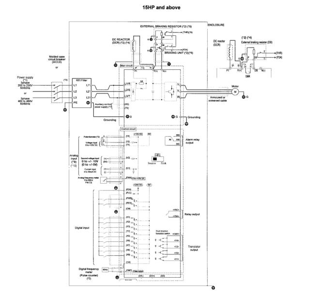
Basic Connection Diagram (Sink Logic)
G11S:15HP and above |
|
|
|
|
|
G11S:Up to 10HP |
|||
P11S:20HP and above |
|
|||
|
P11S:Up to 15HP |
|||
|
|
|||
|
|
|
|
|
|
|
|
|
|
|
|
|
DB) |
|
|
|
|
|
(CM) |
|
|
|
|
|
|
|
|
|
(THR) |
|
|
|
|
|
Ground-fault circuit interrupter (GFCI)
RS-485
Fig.2-3-1
Note: The control circuit common terminals [11], (CM) and <CMY> are isolated
(*1) Use a drive with rated voltage matching the power supply voltage. (*2) Use as required.
(*3) Use this peripheral device when necessary.
(*4) Remove the jumper wire (*4) between P1 and P(+) before connecting a DC REACTOR.
(*5) Be sure to use the braking unit (option)(*6) when connecting the external braking resistor (option)(*5) (*6) Connect the braking unit to P(+) ans N(-). The auxiliary terminals [1] and [2] have polarity.
Connect them as shown in the figure above.
(*7) The drive can be operated without connecting the auxiliary control power supply. (*8) Terminal (X1) to (X9) can be set to 9 (THR) - Braking unit thermal trip input.
(*9) If usingV2 or C1, as a reference signal, they must be used exclusively.
(*10) It is possible to input voltage signals (0 to +10 VDC or 0 to +5 VDC) to terminals [12] [11] instead of the potentiometer.
2-4

Basic Connection Diagram to PLC (Sink Logic)
G11S:15HP and above |
|
|
|
G11S:Up to 10HP |
|
P11S:20HP and above |
|
|
|
P11S:Up to 15HP |
|
|
|
|
|
|
|
|
|
|
Ground-fault circuit interrupter (GFCI)
RS-485
Fig.2-3-2
2-5
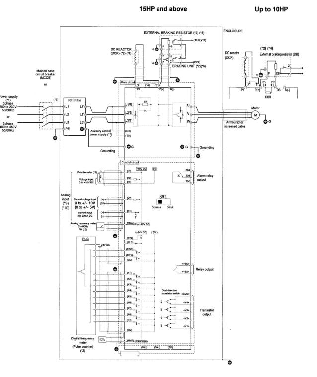
Basic Connection Diagram (Source Logic, Typically used in Europe)
G11S:15HP and above |
G11S:Up to 10HP |
P11S:20HP and above |
P11S:Up to 15HP |
|
|
Ground-fault circuit interrupter (GFCI)
RS-485
Fig.2-3-3
Note: The control circuit common terminals [11], (CM) and <CMY> are isolated
(*1) Use a drive with rated voltage matching the power supply voltage. (*2) Use as required.
(*3) Use this peripheral device when necessary.
(*4) Remove the jumper wire (*4) between P1 and P(+) before connecting a DC REACTOR.
(*5) Be sure to use the braking unit (option)(*6) when connecting the external braking resistor (option)(*5) (*6) Connect the braking unit to P(+) ans N(-). The auxiliary terminals [1] and [2] have polarity.
Connect them as shown in the figure above.
(*7) The drive can be operated without connecting the auxiliary control power supply. (*8) Terminal (X1) to (X9) can be set to 9 (THR) - Braking unit thermal trip input.
(*9) If usingV2 or C1, as a reference signal, they must be used exclusively.
(*10) It is possible to input voltage signals (0 to +10 VDC or 0 to +5 VDC) to terminals [12] [11] instead of the potentiometer
2-6
Basic Connection Diagram to PLC (Source logic, Typically used in Europe)
G11S:15HP and above |
|
G11S:Up to 10HP |
P11S:20HP and above |
|
P11S:Up to 15HP |
|
|
|
|
|
|
(THR)
(P24)
Ground-fault circuit interrupter (GFCI)
RS-485
Fig.2-3-4
2-7

2-3-2 Connecting the main circuit and ground terminals
Table 2-3-1 Functions of main circuit terminals and ground terminals
Symbol |
Terminal name |
Description |
|
L1/R, L2/S, L3/T |
Main circuit power terminal |
Connects a 3-phase power supply. |
|
U, V, W |
Inverter output terminal |
Connects a 3-phase motor. |
|
|
Auxiliary control-power |
Connects a backup AC power supply to the |
|
R0, T0 |
control circuit. (Not supported for inverter of 1HP |
||
input terminal |
|||
|
or less) |
||
|
|
||
P1, P (+) |
DC reactor connecting |
Connects the optional power-factor correcting DC |
|
terminal |
reactor. |
||
|
|||
P (+), DB |
External braking resistor |
Connects the optional external braking resistor. |
|
connecting terminal |
(For inverter of 10HP or less) |
||
|
|||
P (+), N (-) |
DC link circuit terminal |
Supplies DC link circuit voltage to the external |
|
braking unit (option) or power regeneration unit |
|||
|
|
(option). |
|
G |
Inverter ground terminal |
Grounds the inverter chassis (case) to the earth. |
(1)Main circuit power terminals (L1/R, L2/S, L3/T)
Connect these terminals to the power supply via a molded-case circuit breaker or a ground-fault circuit interrupter for circuit (wiring) protection. Phase-sequence matching is unnecessary.
To ensure safety, a magnetic contactor should be connected to disconnect the inverter from the power supply when the inverter protective function activates.
Use control circuit terminal FWD/REV or the RUN/STOP key on the keypad panel to start or stop the inverter. The main circuit power should be used to start or stop the inverter only if absolutely necessary and then should not be used more than once every hour.
If you need to connect these terminals to a single-phase power supply, please contact the factory.
(2)Inverter output terminals (U, V, W)
Connect these terminals to a 3-phase motor in the correct phase sequence. If the direction of motor rotation is incorrect, exchange any two of the U, V, and W phases.
Do not connect a power factor correction capacitor or surge absorber to the inverter output.
If the cable from the inverter to the motor is very long, a high-frequency current may be generated by stray capacitance between the cables and result in an overcurrent trip of the inverter, an increase in leakage current, or a reduction in current indication precision.
When a motor is driven by a PWM-type drive, the motor terminals may be subject to surge voltage generated by drive element switching. If the motor cable (with 460V series motors, in particular) is particularly long, surge voltage will deteriorate motor insulation. To prevent this, use the following guidelines:
Inverters 7.5 HP and larger
Motor Insulation Level |
1000V |
1300V |
1600V |
460 VAC Input Voltage |
66 ft (20 m) |
328 ft (100 m) |
1312 ft (400 m) * |
230 VAC Input Voltage |
1312 ft (400 m) * |
1312 ft (400 m) * |
1312 ft (400 m) * |
|
|
|
|
Inverters 5 HP and smaller |
|
|
|
Motor Insulation Level |
1000V |
1300V |
1600V |
460 VAC Input Voltage |
66 ft (20 m) |
165 ft (50 m) * |
165 ft (50 m) * |
230 VAC Input Voltage |
328 ft (100 m) * |
328 ft (100 m) * |
328 ft (100 m) * |
* For this case the cable length is determined by secondary effects and not voltage spiking.
Note: When a motor protective thermal O/L relay is inserted between the inverter and the motor, the thermal O/L relay may malfunction (particularly in the 460V series), even when the cable length is 165 feet (50m) or less. To correct, insert a filter or reduce the carrier frequency. (Use function code “F26 Motor sound”.)
2-8
(3) Auxiliary control-power input terminals (R0 and T0)
The inverter operates even if power is not provided to these terminals.
If a protective circuit operates and the magnetic contactor on the inverter power side is opened (off), the inverter control circuit power, the alarm output (30A, B, and C), and the keypad panel display goes off. To prevent this, the same AC power as the main circuit AC power must be supplied (as auxiliary control power) to the auxiliary control-power input terminals (R0 and T0).
To ensure effective noise reduction when using a radio noise filter, the output power from the filter must go to the auxiliary control-power input terminals.
|
|
Inverter |
|
Noise filter |
Magnetic |
Power supply |
RCD |
contactor |
|
|
L1/R |
|
|
L2/S |
|
|
L3/T |
|
Insulation Transformer |
|
|
|
R0 |
|
|
T0 |
P1 |
P(+) |
|
|
+ |
|
+ |
DC/DC |
Inverter |
|
control power |
Fig. 2-3-5 Connecting the auxiliary control-power input terminals
If these terminals are connected to the input side of the filter, the noise reduction effect deteriorates.
When the RCD (Residual-current Protective Device) is installed (G11S:30HP or less), the terminal R0 and T0 should be connected to the OUTPUT side of the RCD. If they are connected to the input side of the RCD, RCD will be malfunction because the power supply of the inverter is three phase and the terminal R0 and T0 is single phase.
When the terminal R0 and T0 are connected to the INPUT side of the RCD, the insulation transformer is required to install as shown on the Fig. 2-3-5.
(4)DC reactor connecting terminals (P1 and P (+))
Before connecting a power-factor correcting DC reactor (optional) to these terminals, remove the factory-installed jumper.
If a DC reactor is not used, do not remove the jumper.
Note:For inverter of 100HP or more, the DC reactor is provided as a separate
standard component and should always be connected to the terminals. |
Fig. 2-3-6 |
|
(5) External braking-resistor connecting terminals (P (+) and DB) (G11S:10HP or less)
For the G11S of 10HP or less, a built-in braking resistor is connected to terminals P (+) and DB.
If this braking resistor does not provide sufficient thermal capacity (e.g., in highly repetitive operation or heavy inertia load operation), an external braking resistor (option) must be mounted to improve braking performance.
Remove the built-in braking resistor from terminals P(+) |
DC reactor |
External braking resistor (DB) |
|
||
and DB. Insulate the resistor-removed terminals with |
(DCR) |
|
|||
|
|
|
|
||
adhesive insulation tape, etc. |
|
|
|
2 |
(THR) |
Connect terminals P(+) and DB of the external braking |
|
|
|
||
|
|
|
|
||
resistor to terminals P(+) and DB of the inverter. |
|
P |
DB |
1 |
(P24) |
The wiring (cables twisted or otherwise) should not |
|
|
|
|
|
exceed 16ft (5m). |
|
[ x |
x ] |
|
|
(6) DC link circuit terminals (P (+) and N (-)) |
P1 |
P(+) |
DB |
N(-) |
|
The G11S inverter of 15HP or more does not contain a |
|
DBR |
|
|
|
drive circuit for the braking resistor. To improve braking |
Fig. 2-3-7 Connection (G11S:10HP or less) |
||||
performance, an external braking unit (option) and an external braking resistor (option) must be installed.
Connect terminals P(+) and N(-) of the braking unit |
|
External braking resistor (DB) |
|
||
to terminals P(+) and N(-) of the inverter. The |
|
|
|||
wiring (cables twisted or otherwise) should not |
|
|
|
2 |
(THR) |
exceed 16ft(5m). |
|
|
|
|
|
|
|
|
|
|
|
Connect terminals P(+) and DB of the braking |
DC reactor |
P |
DB |
1 |
|
resistor to terminals P(+) and DB of the braking unit. |
|
|
|
|
|
The wiring (cables twisted or otherwise) should not |
(DCR) |
|
|
|
|
|
P |
DB |
2 |
|
|
exceed 33ft (10m). When terminals P (+) and N (-) |
|
|
|||
|
|
|
|
|
|
of the inverter are not used, leave terminals open. |
|
P |
N |
1 |
(P24) |
If P (+) is connected to N (-) or the braking resistor |
|
|
|
Braking unit (BU) |
|
is connected directly, the resistor will break. |
P1 |
P(+) |
N(-) |
|
|
Auxiliary contacts 1 and 2 of the braking unit have |
|
|
|||
polarity. To connect the power regeneration unit, refer |
|
|
|
|
|
to the "Power Regeneration Unit Instruction Manual". |
|
|
|
|
|
|
Fig. 2-3-8 Connection (G11S:15HP or more) |
|
|||
2-9

(7) Inverter ground terminal
To ensure safety and noise reduction, always ground the inverter ground terminal. Also, metal frames of electrical equipment must be grounded as specified in the Electric Facility Technical Standard.
The connection procedure is as follows:
Ground metal frames to a ground terminal (Ground resistance:10Ω or less).
Use a suitable cable (short and thick) to connect the inverter system to the ground terminal.
(8)Auxiliary power switching connector (CN UX) (for inverter of 40HP or more)
When an inverter of 40HP or more requires a main circuit power voltage as listed in Table 2-3-2, disconnect auxiliary power switching connector CN UX from U1 and connect to U2. For the switching method, see Fig. 2-3-11.
Table 2-3-2 Main circuit power voltage requiring auxiliary power switching connector switching
|
|
|
Frequency [Hz] |
|
Power voltage range [VAC] |
|
|
|
|
|
|
|
|
|
|
|
50 |
|
|
380-398 |
|
||
|
60 |
|
|
380-430 |
|
||
|
|
|
|
|
|
|
|
|
|
|
|
|
|
||
|
|
|
|
• |
Check that the number of phases and rated voltage of this product match |
||
|
|
|
|
|
those of the AC power supply. |
||
|
|
CAUTION |
• Do not connect the AC power supply to the output terminals (U, V, W). |
||||
|
|
Injury may result. |
|||||
|
|
|
|
||||
|
|
|
|
• Do not connect a braking resistor directly to the DC terminals (P[+] and N[-]). |
|||
|
|
|
|
Fire may result. |
|||
(9) Fan power switching connector (CN RXTX) (for inverter of 40HP or more)
G11S without options supports DC power input via DC common connection by connecting the power regeneration converter (RHC series) as shown in Fig. 2-3-10.
For details, refer to technical documentation.
The inverter of 40HP or more contains an AC-powered component (e.g., AC cooling fan).
To use the inverter using DC power input, switch the fan power switching connector (CN RTXT) inside the inverter to the R0-T0 side and provide AC power to the R0 and T0 terminals. (See Fig. 2-3-9.)
For the switching method, see Fig. 2-3-11.
Note:
In the standard state, the fan power switching connector (CN RXTX) is connected to the L1/R-L3/T side. When DC power input is not used, do not switch this connector.
The same AC voltage as the main circuit power voltage must be supplied to the auxiliary control-power input terminals (R0 and T0). If not supplied, the fan does not rotate and the inverter will overheat (0H1).
2-10

30kW40HP ormore
MCCB Noise filter
Power supply
Jumper (not supplied for inverter of 100HP or more)
Jumper (not supplied for inverter of 75kW or more)
|
Inverter |
P1 |
P(+) |
N(-) |
|
Magnetic |
|
|
|
F |
|
|
|
|
|
|
|
contactor |
|
|
|
|
|
L1/R |
|
|
|
|
|
|
|
|
|
U |
M |
|
|
+ |
C |
|
|
L2/S |
|
|
|
WV |
|
L3/T |
|
|
|
|
|
CN RX |
TX |
Fan |
|
|
|
|
|
|
|
|
|
|
|
CN RX |
TX |
|
|
R0 |
|
|
|
|
|
T0 |
|
|
|
|
|
|
|
|
R0 |
|
|
|
|
|
T0 |
|
|
When switched to DC power input mode
Fig. 2-3-9 Fan power switching
PWM converter
30kW40HP ormore |
P(+) |
Power supply |
|
R |
C |
+ |
|
S |
|
T |
|
N(-)
|
|
|
|
Inverter |
|
|
|
|
|
|
|
|
|
|
|
|
|
P1 |
P(+) |
N(-) |
|
|
|||||||||||||||||||||||||||||||||||
|
L1/R |
|
|
|
|
|
|
|
|
|
|
|
|
|
|
|
|
|
|
|
|
|
|
|
F |
|
|
|
|
|
|
|
|
|
|
|
|
|
|
|
|
|
|
|
|
|
|
|
|
U |
|
||||||
|
|
|
|
|
|
|
|
|
|
|
|
|
|
|
|
|
|
|
|
|
|
|
|
|
|
|
|
|
|
|
|
|
|
|
|
|
|
|
|
|
|
|
|
|
|
|
|
|
|
||||||||
|
|
|
|
|
|
|
|
|
|
|
|
|
|
|
|
|
|
|
|
|
|
|
|
|
|
|
|
|
|
|
|
|
|
|
|
|
|
|
|
|
|
|
|
|
|
|
|
|
|
||||||||
|
|
|
|
|
|
|
|
|
|
|
|
|
|
|
|
|
|
|
|
|
|
|
|
|
|
+ |
|
C |
|
|
|
|
|
|
|
|
|
|
|
|
|
|
|
|
|
|
|
|
|
|
|
|
|
|
|||
|
L2/S |
|
|
|
|
|
|
|
|
|
|
|
|
|
|
|
|
|
|
|
|
|
|
|
|
|
|
|
|
|
|
|
|
|
|
|
|
|
|
|
|
|
|
|
|
|
|
|
|
W |
M |
||||||
|
|
|
|
|
|
|
|
|
|
|
|
|
|
|
|
|
|
|
|
|
|
|
|
|
|
|
|
|
|
|
|
|
|
|
|
|
|
|
|
|
|
|
|
|
|
|
|
|
|
|
|
||||||
|
|
|
|
|
|
|
|
|
|
|
|
|
|
|
|
|
|
|
|
|
|
|
|
|
|
|
|
|
|
|
|
|
|
|
|
|
|
|
|
|
|
|
|
|
|
|
|
|
|
V |
|
||||||
|
L3/T |
|
|
|
|
|
|
|
|
|
|
|
|
|
|
|
|
|
|
|
|
|
|
|
|
|
|
|
|
|
|
|
|
|
|
|
|
|
|
|
|
|
|
|
|
|
|
|
|
|
|
|
|
|
|
||
|
|
|
|
|
|
|
|
|
|
|
|
|
|
|
|
|
|
|
|
|
|
|
|
|
|
|
|
|
|
|
|
|
|
|
|
|
|
|
|
|
|
|
|
|
|
|
|
|
|
|
|
||||||
|
CN RX TX |
|
|
Fan |
|
|
|
|
|
|
|
|
|
|
|
|
|
|
|
|
|
|
|
|
|
|
|
|
|
|
|
|
|
|
|
|
|
|
|
|
|
|
|||||||||||||||
|
|
|
|
|
|
|
|
|
|
|
|
|
|
|
|
|
|
|
|
|
|
|
|
|
|
|
|
|
|
|
|
|
|
|
|
|
|
|
|
|
|
|
|
|
|
|
|
||||||||||
|
R0 |
|
|
|
|
|
|
|
|
|
|
|
|
|
|
|
|
Switch CNRXTX to the |
R0-T0 |
side. |
|
|
|||||||||||||||||||||||||||||||||||
|
|
|
|
|
|
|
|
|
|
|
|
|
|
|
|
|
|||||||||||||||||||||||||||||||||||||||||
|
|
|
|
|
|
|
|
|
|
|
|
|
|
|
|
|
|
||||||||||||||||||||||||||||||||||||||||
|
|
|
|
|
|
|
|
|
|
|
|
|
|
|
|
|
|
|
|
|
|
|
|
|
|
|
|
|
|
|
|
|
|
|
|
|
|
|
|
|
|
|
|
|
|
|
|
|
|
|
|
|
|
||||
|
|
|
|
|
|
|
|
|
|
|
|
|
|
|
|
|
|
|
|
|
|
|
|
|
|
|
|
|
|
|
|
|
|
|
|
|
|
|
|
|
|
|
|
|
|
|
|
|
|
|
|
|
|
||||
|
|
|
|
|
|
|
|
|
|
|
|
|
|
|
|
|
|
|
|
|
|
|
|
|
|
|
|
|
|
|
|
|
|
|
|
|
|
|
|
|
|
|
|
|
|
|
|
|
|
|
|
|
|
||||
|
|
|
|
|
|
|
|
|
|
|
|
|
|
|
|
|
|
|
|
|
|
|
|
|
|
|
|
|
|
|
|
|
|
|
|
|
|
|
|
|
|
|
|
|
|
|
|
|
|
|
|
|
|
||||
|
T0 |
|
|
|
|
|
|
|
|
|
|
|
|
|
|
|
|
|
|
|
|
|
|
|
|
|
|
|
|
|
|
|
|
|
|
|
|
|
|
|
|
|
|
|
|
|
|
|
|
|
|||||||
Fig. 2-3-10A Example of connection by combination with power regeneration converter(40HP or more)
Note:
To connect the power regeneration converter to an inverter of 30HP or less, do not connect the power supply directly to the auxiliary control-power input terminals (R0 and T0) of the inverter. However, if such a connection is required, insulate these input terminals from the main power of the power regeneration converter with an insulation transformer. The connection example of a power regeneration unit is provided in the "Power Regeneration Unit Instruction Manual".
Noise filter |
Magnetic |
RHC series |
FRN-G11S |
|
MCCB or RCD |
contactor |
|
|
|
|
|
|
|
|
|
|
L1/R |
L1/R |
|
|
|
|
U |
M |
Power supply |
|
L2/S |
V |
|
|
|
|
W |
|
|
|
L3/T |
L3/T |
|
|
|
R1 |
|
|
|
|
S1 |
|
|
|
|
T1 |
|
|
|
|
|
R0 |
|
|
|
|
T0 |
|
|
Insulation Transformer |
|
|
|
Fig. 2-3-10B Example of connection by combination with power regeneration converter (30HP or less)
2-11

The switching connectors are mounted on the power PCB above the control PCB as shown on the right.
Note:
To remove a connector, unlock the connector (using the locking mechanism) and pull. To mount a connector, push the connector until it click locks.
FRN040G11S-4UX to FRN150G11S-4UX
FRN200G11S-4UX to FRN350G11S-4UX
<Enlarged view of part A>
When shipped from the factory, CN UX is connected to the U1 side
and CN RXTX is connected to the L1/R-L3/T side.
<Oblique view of part A>
Factory shipment status Connector removal After connector switching.
CNUX |
: U1 |
In this figure the power voltage is 380 to 398V AC, 50Hz (or 380 to |
|
CNRXTX |
: |
|
430V AC, 60Hz) and the inverter is used in DC power input mode. |
L1/R-L3/T |
|||
Fig. 2-3-11 Power switching connectors (only for 40HP or more)
2-12
2-3-3 Connecting the control terminals
Table 2-3-3 lists the functions of the control circuit terminals. A control circuit terminal should be connected according to the setting of its functions.
Table 2-3-3
Classification |
Terminal |
Terminal name |
|
|
|
Function |
|
|
|
|
|
|
symbol |
|
|
|
|
|
|
|
|
|
|||
|
|
|
|
|
|
|
|
|
|
|
|
|
|
13 |
Potentiometer power |
Used for +10V DC power supply for frequency setting POT (variable |
|||||||||
|
|
supply |
resistor of 1 to 5kΩ) |
|
|
|
|
|
|
|||
|
12 |
Voltage input |
Frequency is set according to the analog input voltage supplied from |
|||||||||
|
|
|
|
|
an external circuit. |
|
|
|
|
|
|
|
|
|
|
|
|
- 0 to +10V DC/0 to 100% |
|
|
|
|
|
|
|
|
|
|
|
|
- Reversible operation using positive and negative signals:0 to +/- |
|||||||
|
|
|
|
|
10V DC/0 to 100% |
|
|
|
|
|
|
|
|
|
|
|
|
- Reverse operation: +10 to 0V DC/0 to 100% |
|
|
|
|
|||
|
|
|
The feedback signal for PID control is input. |
|
|
|
|
|||||
|
|
|
The analog input value from the external circuit is used for torque |
|||||||||
|
|
|
|
|
control. (P11S does not support this function.) |
|
|
|
|
|||
|
|
|
* |
Input resistance: 22kΩ |
|
|
|
|
|
|
||
Analog input |
V2 |
Voltage input |
Frequency is set according to the analog input voltage supplied from an |
|||||||||
|
|
external circuit |
|
|
|
|
|
|
||||
|
|
|
|
|
- 0 to +10V DC/0 to 100% |
|
|
|
|
|
|
|
|
|
|
|
|
- Reverse operation:+10 to 0V DC/0 to 100% |
|
|
|
|
|||
|
|
|
* It can be used only one terminal "V2" or "C1" alternatively |
|
|
|||||||
|
|
|
* |
Input resistance:22kΩ |
|
|
|
|
|
|
||
|
C1 |
Current input |
Frequency is set according to the analog input current supplied from |
|||||||||
|
|
|
|
|
an external circuit. |
|
|
|
|
|
|
|
|
|
|
|
|
- 4 to 20mA DC/0 to 100% |
|
|
|
|
|
|
|
|
|
|
|
|
- Reverse operation:20 to 4mA DC/0 to 100% |
|
|
|
|
|||
|
|
|
The feedback signal for PID control is input. |
|
|
|
|
|||||
|
|
|
PTC thermistor input |
|
|
|
|
|
|
|||
|
|
|
* It can be used only one terminal "V2" or "C1" alternatively. |
|
|
|||||||
|
|
|
* |
Input resistance:250Ω |
|
|
|
|
|
|
||
|
11 |
Analog input common |
Common terminal for analog input signals |
|
|
|
|
|
|
|||
|
FWD |
Forward operation/stop |
Used for forward operation (when FWD-CM is on) or deceleration and |
|||||||||
|
|
command |
stop (when FWD-CM is off) |
|
|
|
|
|
|
|||
|
REV |
Reverse operation/stop |
Used for reverse operation (when REV-CM is on) or deceleration and |
|||||||||
|
|
command |
stop (when REV-CM is off) |
|
|
|
|
|
|
|||
|
X1 |
Digital input 1 |
The coast-to-stop command, external alarm, alarm reset, multistep |
|||||||||
|
X2 |
Digital input 2 |
frequency selection, and other functions (from an external circuit) can be |
|||||||||
|
X3 |
Digital input 3 |
assigned to terminals X1 to X9. For details, see "Setting the Terminal |
|||||||||
|
Functions E01 to E09" in Section 5.2, "Details of Each Function." |
|||||||||||
|
X4 |
Digital input 4 |
||||||||||
|
<Specifications of digital input circuit> |
|
|
|
|
|
|
|||||
|
X5 |
Digital input 5 |
|
|
|
|
|
|
||||
|
* |
|
|
|
|
|
|
|
|
|||
|
X6 |
Digital input 6 |
|
|
Item |
min. |
|
typ. |
|
max. |
|
|
|
|
|
|
|
Operating voltage |
ON level |
2V |
|
- |
|
2V |
|
|
X7 |
Digital input 7 |
|
|
||||||||
|
|
|
OFF level |
22V |
|
24V |
|
27V |
|
|||
|
X8 |
Digital input 8 |
|
|
|
|
|
|
||||
Digital input |
|
|
Operating current at ON level |
- |
|
3.2mA |
|
4.5mA |
|
|||
X9 |
Digital input 9 |
|
|
|
|
|
|
|
|
|
||
|
|
Allowable leakage current at OFF level |
- |
|
- |
|
0.5mA |
|
||||
|
|
|
|
|
|
|
|
|||||
|
CM |
Common terminal |
Common terminal for Digital input and FMP terminals |
|
|
|
|
|||||
|
P24 |
Control Unit power Supply |
+24VDC power supply for control input. Maximum output current 100mA |
|||||||||
|
PLC |
PLC signal power |
Used to connect power supply for PLC output signals (rated voltage |
|||||||||
|
|
|
24(22 to 27) V DC) at source logic operation. |
|
|
|
|
|||||
|
FMA |
Analog monitor |
|
Outputs monitor signal using analog DC voltage 0 to +10V DC. |
|
|
||||||
|
(11: |
|
The meaning of this signal is one of the following: |
|
|
|
|
|||||
|
Common |
|
-Output frequency (before slip compensation) -Power consumption |
|||||||||
|
terminal) |
|
-Output frequency (after slip compensation) -PID feedback value |
|||||||||
Analog output |
|
|
-Output current -PG feedback value |
|
|
|
|
|
|
|||
|
|
|
-Output voltage -DC link circuit voltage |
|
|
|
|
|
|
|||
|
|
|
-Output torque -Universal AO |
|
|
|
|
|
|
|||
|
|
|
-Load factor |
|
|
|
|
|
|
|||
|
|
|
*Connectable impedance:5kΩ minimum |
|
|
|
|
|
|
|||
2-13
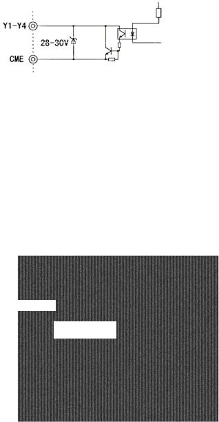
|
FMP |
Frequency monitor |
Outputs a monitor signal using the pulse waveform. |
|
|
|
|
|||||||
Pulse output |
(CM: |
(pulse waveform output) |
This signal has the same function as the FMA signal. |
|
|
|
|
|||||||
Common |
|
|
|
|
|
|
|
|
|
|
|
|
||
|
|
|
|
|
|
|
|
|
|
|
|
|
||
|
terminal) |
|
|
|
|
|
|
|
|
|
|
|
|
|
|
|
|
|
A running signal, frequency equivalence signal, overload early warning |
||||||||||
|
Y1 |
Transistor output1 |
|
signal, and other signals from the inverter are output (as transistor |
||||||||||
|
|
|
|
output) to arbitrary ports, For details, see "Setting the Terminal |
||||||||||
|
Y2 |
Transistor output2 |
|
Functions E20 to E23" in Section 5.2, "Details of Each Function." |
||||||||||
|
Y3 |
Transistor output3 |
|
|
<Specifications of transistor output circuit> |
|
|
|||||||
|
Y4 |
Transistor output4 |
* |
|
|
|||||||||
|
|
|
|
|
|
|
|
|
|
|||||
|
|
|
|
|
|
|
|
|
|
|
|
|||
|
|
|
|
|
Item |
|
min. |
|
typ. |
|
max. |
|
||
|
|
|
|
Operating |
|
ON level |
|
- |
|
2V |
|
3V |
|
|
|
|
|
|
voltage |
|
OFF level |
|
- |
|
24V |
|
27V |
|
|
Transistor |
|
|
|
Maximum load current at ON level |
|
- |
|
- |
|
50mA |
|
|||
|
|
|
Leakage current at OFF level |
|
- |
|
- |
|
0.1mA |
|
||||
output |
|
|
|
|
|
|
|
|||||||
|
|
|
|
|
|
|
|
|
|
|
|
|
||
|
|
|
|
|
|
|
|
|||||||
|
CME |
Transistor output |
Common terminal for transistor output signals |
|
|
|
|
|||||||
|
|
common |
This terminal is insulated from terminals [CM] and [11]. |
|
|
|
|
|||||||
|
30A,30B, |
Alarm output for any fault |
If the inverter is stopped by an alarm (protective function), the alarm |
|||||||||||
|
30C |
|
|
signal is output from the relay contact output terminal (1SPDT). |
|
|
||||||||
|
|
|
|
Contact rating: 48V DC, 0.5A |
|
|
|
|
|
|
||||
|
|
|
|
An excitation mode (excitation at alarm occurrence or at normal |
|
|
||||||||
Relay output |
|
|
|
operation) can be selected. |
|
|
|
|
|
|
||||
Y5A,Y5C |
Multipurpose-signal relay |
These signals can be output similar to the Y1 to Y4 signals above. |
||||||||||||
|
||||||||||||||
|
|
output |
The contact rating for any fault is the same as that of the alarm output |
|||||||||||
|
|
|
above. |
|
|
|
|
|
|
|
|
|
||
|
|
|
An excitation mode (excitation at alarm occurrence or at normal |
|
|
|||||||||
|
|
|
operation) can be selected. |
|
|
|
|
|
|
|||||
|
DX+, DX- |
RS-485 communication |
Input-output signal terminals for RS-485 communication. UP to 31 |
|||||||||||
Communication |
|
input-output |
inverters can be connected using the daisy chain method. |
|
|
|||||||||
SD |
Communication-cable |
Terminal for connecting the shield of a cable. |
The terminal is |
|
|
|||||||||
|
|
shield connection terminal |
electrically floating. |
|
|
|
|
|
|
|||||
(1)Analog input terminals (13,12,V2,C1,and 11)
These terminals receive weak analog signals that may be affected by external noise. The cables must be as short as possible (66ft (20m) or less), must be shielded, and must be grounded in principle. If the cables are affected by
external induction noise, the shielding effect may be 0k to 5 kΩ improved by connecting the shield to terminal [11].
Fig. 2-3-12
If contacts must be connected to these circuits, twin (bifurcated type) contacts for handling weak signals must be used. A contact must not be connected to terminal [11].
If an external analog signal output device is connected to these terminals, it may malfunction as a result of inverter noise. To prevent malfunction, connect a ferrite core or capacitor to the external analog signal output device.
Fig. 2-3-13 Example of noise prevention
2-14

(2) Digital input terminals (FWD, REV, X1 to X9 and CM)
Digital input terminals (e.g., FWD, REV, X1 to X9) are generally turned on or off by connecting or disconnecting the line to or from the CM terminal. If Digital input terminals are turned on or off by switching the open collector output of PLC using an external power supply, a resulting bypass circuit may cause the inverter to malfunction.
To prevent a malfunction, connect the PLC terminal as shown in Fig. 2-3-14.
When using a contact input, a relay having highly reliable contact must be used.
Example: Fuji Electric Control Relay:HH54PW
Programmable
Logic controller
Fig. 2-3-14
Connection for External power supply
(3)Transistor output terminals (Y1 to Y4, CME)
To connect a control relay, connect a surge absorbing diode to both ends of its exciting coil.
(4)Others
To prevent a malfunction as a result of noise, control terminal cables must be placed as far as possible from the main circuit cables.
The control cables inside the inverter must be secured to prevent direct contact with live section (e.g., main-circuit terminal block) of the main circuit.
WARNING
CAUTION
Control lines generally do not have enhanced insulation. If the insulation of a control line is damaged, the control signals may be exposed to high voltage in the main circuit. The Low Voltage Directive in Europe also restricts the exposure to high voltage.
Electric shock may result
The inverter, motor, and cables generate noise.
Check that the ambient sensors and devices do not malfunction.
Accident may result.
(5)Wiring of control circuit (inverter of 40HP or more)
Pull out the control circuit wiring along the left panel as shown in Fig. 2-3-15.
Secure the cable to cable binding hole A (on the left wall of the main circuit terminal block) using a cable-tie (e.g., insulock). The cable-tie must not exceed 0.14inch (3.5mm) in width and 0.06inch (1.5mm) in thickness.
When the optional PC board is mounted, the signal lines must be secured to cable binding hole B.
|
Fig. 2-3-16 The securing positions of the |
|
control-circuit line of inverter |
Fig. 2-3-15 The wiring route of the control circuit |
(40HP or more) |
2-15
2-3-4 Terminal arrangement
(1) Main circuit terminals
FRNF25 to 001G11S-2UX |
|
|
|
|
|
|
|
|
|
|
|
|
|
|
FRN100G11S-2UX /FRN125P11S-2UX |
|
|
|
|
|
|
|
|
|
|
||||||||||||||||||||||||||||||||||||||||||||||||
FRNF50 to 001G11S-4UX |
|
|
|
|
Screw size M3.5 |
|
|
|
|
|
|
|
|
|
|
|
|
|
|
|
|
Screw size M4 |
|
|
|
|
|
|
|
|
|
|
|
|
|
|
|
||||||||||||||||||||||||||||||||||||
|
|
|
|
|
|
|
|
|
|
|
|
R0 |
T0 |
|
|
|
|
|
|
|
|
|
|
|
|
|
|
|
|||||||||||||||||||||||||||||||||||||||||||||
|
|
|
|
|
|
|
|
|
|
|
|
|
|
|
|
|
|
|
|
|
|
|
|
|
|
|
|
|
|
|
|
|
|
|
|
|
|
|
|
|
|
|
|
|
|
|
|
|
|
|
|
|
|
|
|
|
|
|
|
|
|
|
|
|
|
||||||||
|
|
|
|
|
|
|
|
|
|
|
|
|
|
|
|
|
|
|
|
|
|
|
|
|
|
|
|
|
|
|
|
|
|
|
|
|
|
|
|
|
|
|
|
|
|
|
|
|
|||||||||||||||||||||||||
|
|
|
|
|
|
|
|
|
|
|
|
|
|
|
|
|
|
|
|
|
|
|
|
|
|
|
|
|
|
L1/R |
|
L2/S |
L3/T |
P1 |
|
P(+) |
|
N(-) |
|
|
|
|
U |
|
V |
|
W |
|
|||||||||||||||||||||||||
|
|
L1/R |
L2/S |
L3/T |
DB |
P1 |
P(+) |
N(-) |
U |
V |
|
W |
|
|
|
|
|||||||||||||||||||||||||||||||||||||||||||||||||||||||||
|
|
|
|
|
|
|
|
|
|
|
|
|
|
|
|
|
|
|
|
|
|
|
|
|
|
|
|
|
|
|
|
|
|
|
|
|
|
|
|
|
|
|
|
|
|
|
|
|
|
|
|
|
|
|
|
|
|
|
|
|
|
|
|
|
|
|
|
|
|
|
|
|
|
|
|
G |
|
|
|
|
|
|
|
|
|
|
|
|
|
Screw size M3.5 |
|
|
|
|
|
|
|
|
|
G |
|
|
G |
|
|
|
|
|
Screw size |
|
|
G: |
M10 |
|
|
|
|
|
|
||||||||||||||||||||||||||||
|
|
|
|
|
|
|
|
|
|
|
|
|
|
|
|
|
|
|
|
|
|
|
|
|
|
|
|
|
|
|
|
|
|
|
|
|
other terminals : |
M12 |
|
|
|
|
|
|
|||||||||||||||||||||||||||||
|
|
G |
|
|
|
|
|
|
|
|
|
|
|
|
|
|
|
|
|
|
|
|
|
|
|
|
|
|
|
|
|
|
|
|
|
|
|
||||||||||||||||||||||||||||||||||||
|
Max. lug width 0.29inch (7.4mm) |
|
|
|
|
|
|
|
|
|
|
|
|
|
|
|
|
|
|
|
|
|
|
|
|
|
|
|
|
|
|
|
|
|
|
|
|||||||||||||||||||||||||||||||||||||
|
|
|
|
|
|
|
|
|
Max. lug width 1.38inch (35mm) |
|
|
|
|
|
|
|
|
|
|
|
|
|
|
|
|||||||||||||||||||||||||||||||||||||||||||||||||
|
|
|
|
|
|
|
|
|
|
|
|
|
|
|
|
|
|
|
|
|
|
|
|
|
|
|
|
|
|
|
|
|
|
|
|
|
|
|
|
|
|
|
|
|
|
|
|
|
|
|
|
|
|
|
|
|
|
|
|
|
|
|
|
|
|
|
|
|
|
|
|
|
|
FRN002 to 005G11S-2UX |
|
|
|
|
|
Screw size M3.5 |
FRN125G11S-2UX /FRN150P11S-2UX |
|
|
|
|
|
|
|
|
|
|
||||||||||||||||||||||||||||||||||||||||||||||||||||||||
FRN002 to 005G11S-4UX |
|
|
|
|
|
FRN200 to 350G11S-4UX /FRN250 to 450P11S-4UX |
|||||||||||||||||||||||||||||||||||||||||||||||||||||||||||||||||||
|
R0 |
|
T0 |
|
|
|
|
|
|
|
|
|
|||||||||||||||||||||||||||||||||||||||||||||||||||||||||||||
|
|
|
|
|
|
|
|
|
|
|
|
|
|
|
|
|
|
|
|
|
|
|
|
|
|
|
|
|
|
|
|
|
|
|
|
|
|
|
|
|
|
Screw size M4 |
|
|
|
|
|
|
|
|
|
|
|||||||||||||||||||||
|
|
|
|
|
|
|
|
|
|
|
|
|
|
|
|
|
|
|
|
|
|
|
|
|
|
|
|
|
|
|
|
|
|
|
R0 |
|
T0 |
|
|
|
|
|
|
|
|
|
|
|
|
||||||||||||||||||||||||
|
|
|
|
|
|
|
|
|
|
|
|
|
|
|
|
|
|
|
|
|
|
|
|
|
|
|
|
|
|
|
|
|
|
|
|
|
|
|
|
|
|
|
|
|
|
|
|
|
|
|
|
|
|
|
|
|
|
|
|
|
|
|
|
|
|
|
|||||||
|
|
L1/R |
|
L2/S |
|
L3/T |
|
DB |
P1 |
P(+) |
|
N(-) |
U |
V |
W |
|
|
|
|
|
|
|
|
|
|
|
|
|
|
|
|
|
|
|
|
|
|
|
|
|
|
|
|
|
|
|
|
|
|
|
|
|
|
|
|
|
|
|
|
|
|
|
|
|
|
|
|||||||
|
|
|
|
|
|
|
|
|
|
|
|
|
|
L1/R |
|
|
|
L2/S |
|
|
L3/T |
|
|
|
|
U |
|
|
|
|
|
|
|
V |
|
|
|
|
W |
|
|||||||||||||||||||||||||||||||||
|
|
G |
|
|
|
|
|
|
|
|
|
|
|
|
|
|
|
|
|
|
|
G |
|
|
|
|
|
|
|
|
|
|
|
|
|
|
|
|
|
|
|
|
|
|
|
|
|
|
|
||||||||||||||||||||||||
|
|
|
|
|
|
|
|
|
|
|
|
|
|
|
|
|
|
|
|
|
|
|
|
|
|
|
|
|
|
|
|
|
|
|
|
|
|
|
|
|
|
|
|
|
|
|
|
|
|
|
|
|
|
|
|
|
|
|
|
|
|
|
|
|
|
|
|
|
|||||
|
|
|
|
|
|
|
|
|
|
|
|
|
|
Screw size M4 |
|
|
|
|
|
|
|
|
|
|
|
|
|
|
|
|
|
|
|
|
|
|
|
|
|
|
|
|
|
|
P1 |
|
|
|
|
P(+) |
|
|
|
N(-) |
|
|
|
|
|||||||||||||||
|
|
|
|
|
|
|
|
|
|
|
|
|
|
|
|
|
|
|
|
|
|
|
|
|
|
|
|
|
|
|
|
|
|
|
|
|
|
|
|
|
|
|
|
|
|
|
|
|
|
|
|
|
|
|
|
|
|
|
|
|
|
|
|
|
|
|
|||||||
|
|
|
|
|
|
|
|
|
|
|
|
|
|
|
|
|
|
|
|
|
|
|
|
|
|
|
|
|
|
|
|
|
|
|
|
|
|
|
|
|
|
|
|
|
|
|
Screw size |
|
G : |
M10 |
|
|
|
|
|
|
|||||||||||||||||
|
|
|
|
|
|
|
|
|
|
|
|
|
|
|
|
|
|
|
|
|
|
|
|
|
|
|
|
|
|
G |
|
G |
|
|
|
|
|
|
|
|
|
|
|
|
|
|
|
||||||||||||||||||||||||||
|
Max. lug width 0.40inch (10.1mm) |
|
|
|
|
|
|
|
|
|
|
|
|
|
|
|
|
|
|
|
|
|
|
|
|
|
|
|
|
other terminals : |
M12 |
|
|
|
|
|
|
||||||||||||||||||||||||||||||||||||
|
|
|
|
|
|
|
|
|
Max. lug width 1.26inch (32mm) |
|
|
|
|
|
|
|
|
|
|
|
|
|
|
|
|||||||||||||||||||||||||||||||||||||||||||||||||
FRN007 to 010G11S-2UX /FRN007 to 015P11S-2UX |
FRN400, 450 G11S-4UX/FRN500, 600 P11S-4UX |
||||||||||||||||||||||||||||||||||||||||||||||||||||||||||||||||||||||||
FRN007 to 010G11S-4UX /FRN007 to 015P11S-4UX |
|
|
|
|
|
|
|
|
|
|
|
|
|
|
|
|
|
|
|
|
|
|
|
|
|
|
|
|
|
|
|
|
|
|
|
|
|
|
|
|
|
|
|
|
|
|
|
||||||||||||||||||||||||||
|
|
|
|
|
|
|
|
|
|
|
|
|
|
|
|
|
|
|
Screw size M3.5 |
|
|
|
|
|
|
R0 |
|
T0 |
|
Screw size M4 |
|
|
|
|
|
|
|
|
|
|
|
|
|
|
|
||||||||||||||||||||||||||||
|
|
|
|
|
|
|
|
|
|
|
|
|
|
R0 |
|
T0 |
|
|
|
|
|
|
|
|
|
|
|
|
|
|
|
|
|
|
|
||||||||||||||||||||||||||||||||||||||
|
|
|
|
|
|
|
|
|
|
|
|
|
|
|
|
|
|
|
|
|
|
|
|
|
|
|
|
|
|
|
|
|
|
|
|
|
|
|
|
|
|
|
|
|
|
|
|
|
|
|
|
|
|
|
|
|
|
|
|
|
|
|
|
|
|
|
|
|
|||||
|
|
L1/R |
L2/S |
L3/T |
DB |
P1 |
P(+) |
N(-) |
U |
V |
W |
|
|
|
|
|
|
|
|
L1/R |
|
|
L2/S |
|
L3/T |
|
|
|
P1 |
|
|
|
U |
|
|
|
V |
|
|
|
W |
|
|
||||||||||||||||||||||||||||||
|
|
|
|
|
|
|
|
|
|
|
|
|
|
|
|
|
|
|
|
|
|
|
|
|
|
|
|
|
|
|
|
|
|
|
|
|
|
|
|
|
|
|
|
|
|
|
|
|
|
||||||||||||||||||||||||
|
|
G |
|
|
|
|
|
|
|
|
|
|
|
Screw size M5 |
|
G |
|
|
|
L1/R |
|
|
|
|
|
L2/S |
|
|
|
L3/T |
|
|
|
|
P1 |
|
|
|
U |
|
|
|
|
|
|
V |
|
|
W |
|
|
|
|
|
|
||||||||||||||||||
|
|
|
|
|
|
|
|
|
|
|
|
|
|
|
|
|
|
|
|
|
|
|
|
|
|
|
|
|
|
|
|
|
|
|
|
|
|
|
|
|
|
|
|
|
|
|
|
|
|
|
|
|
|
|
|
|
|
||||||||||||||||
|
|
|
|
|
|
|
|
|
|
|
|
|
|
|
|
|
|
|
|
|
|
|
|
|
|
|
|
|
|
|
|
|
|
|
|
|
|
|
|
|
|
|
|
|
|
|
|
|
|
|
|
|
|
|
|
|
|
|
|
|
|
|
|
|
|
|
|||||||
|
|
|
|
|
|
|
|
|
|
|
|
|
|
|
|
|
|
|
|
|
|
|
|
|
|
|
|
|
|
|
|
|
|
|
|
|
|
|
|
|
|
|
|
|
|
|
|
|
|
|
|
|
|
|
|
|
|
|
|
|
|
|
|
|
|
|
|||||||
|
Max. lug width 0.53inch (13.5mm) |
|
|
|
|
|
|
|
|
|
|
|
G |
|
|
|
|
|
|
|
|
|
G |
|
|
|
|
P(+) |
|
|
|
P(+) |
|
|
|
|
|
|
|
|
|
|
|
||||||||||||||||||||||||||||||
|
|
|
|
|
|
|
|
|
|
|
|
|
|
|
|
|
|
|
|
|
|
|
|
|
|
|
|
|
|
|
|
|
|
|
|
|
|
|
|
|
|
|
|
|
|
|
|
|
|
|
|
|
|
|
|
||||||||||||||||||
|
|
|
|
|
|
|
|
|
|
|
|
|
|
|
|
|
|
|
|
|
|
|
|
|
|
|
|
|
|
|
|
|
|
|
|
|
|
|
|
|
|
|
|
|
|
|
|
|
|
|
N(-) |
|
|
|
|
N(-) |
|
|
|
|
|
|
|
|
|
|
|
||||||
FRN015 to 030G11S-2UX /FRN020 to 030P11S-2UX |
|
|
|
|
|
|
|
|
|
|
|
|
|
|
|
|
|
|
|
|
|
|
|
|
|
|
|
|
|
|
|
|
|
|
|
|
|||||||||||||||||||||||||||||||||||||
|
|
|
|
|
|
|
|
|
|
|
|
|
|
|
|
|
|
|
|
|
|
|
|
|
|
|
|
|
|
|
|
|
|
|
|
|
|
|
|
|
|
|
|
|
|
|
|||||||||||||||||||||||||||
FRN015 to 030G11S-4UX /FRN020 to 030P11S-4UX |
|
|
|
|
|
|
|
|
|
|
|
|
|
|
|
|
|
|
|
|
|
|
|
|
Screw size G = M10 |
|
|
|
|
|
|
||||||||||||||||||||||||||||||||||||||||||
|
|
|
|
|
|
|
|
|
|
|
|
|
|
R0 |
|
T0 |
|
Screw size M3.5 |
|
|
|
|
|
|
|
|
|
|
|
|
|
|
|
|
|
|
|
|
|
|
|
|
|
|
|
|
|
|
|||||||||||||||||||||||||
|
|
|
|
|
|
|
|
|
|
|
|
|
|
|
|
|
|
|
|
|
|
|
|
|
|
|
|
|
|
|
|
|
|
|
|
|
|
|
|
|
|
|
|
|
|
|
|
|
|
|
Other terminals = M12 |
||||||||||||||||||||||
|
|
|
|
|
|
|
|
|
|
|
|
|
|
|
|
|
|
|
|
|
|
|
|
|
|
|
|
|
|
|
|
|
|
|
|
|
|
|
|
|
|
|
|
|
|
|
|
|
|
|
|||||||||||||||||||||||
|
|
L1/R |
L2/S |
L3/T |
DB |
P1 |
P(+) |
N(-) |
U |
V |
W |
|
Max. lug width 1.26inch (32mm) |
|
|
|
|
|
|
|
|
|
|
|
|
|
|
|
|||||||||||||||||||||||||||||||||||||||||||||
|
|
|
|
|
|
|
|
|
|
|
|
|
|
|
|
|
|
|
|
|
|
|
|
|
|
|
|
|
|
|
|
|
|
|
|
|
|
|
|
|
|
|
|
|
|
|
|
|
|
|
|
|
|
|
|
|
|
|
|
|
|
|
|
|
|
|
|
|
|
|
|
|
|
|
|
|
|
|
|
G |
|
Screw size M6 |
|
|
|
|
|
|
|
|
|
|
|
|
|
|
FRN500, 600 G11S-4UX/FRN700, 800 P11S-4UX |
||||||||||||||||||||||||||||||||||||||||||||||||||
|
|
|
|
|
|
G |
|
|
|
|
|
|
|
|
|
|
|
|
|
|
|
|
|
|
|
|
|
|
|
|
|
|
|
|
|
|
|
|
|
|
|
|
|
|
|
|
|
|
|
|
|
|
|
|
|
|
|
|
|
|
|
|
|
|
|
|
|
|
|||||
|
|
|
|
|
|
|
|
|
|
|
|
|
|
|
|
|
|
|
|
|
|
|
|
|
|
|
|
|
|
|
|
|
|
|
|
|
|
|
|
|
|
|
|
|
|
|
|
|
|
|
|
|
|
|
|
|
|
|
|
|
|
|
|
|
|
|
|
|
|
|
|
|
|
Max. lug width 0.72inch (18.25mm) |
|
|
|
R0 |
T0 |
|
|
|
|
|
|
||||
FRN040G11S-2UX /FRN040 to 050P11S-2UX |
L1/R L2/S |
L3/T |
P1 |
P(+) |
N(-) |
U |
V |
W |
|||||||
FRN040 to 075G11S-4UX /FRN040 to 100P11S-4UX |
|||||||||||||||
L1/R |
L2/S L3/T |
P1 |
P(+) |
N(-) |
U |
V |
W |
||||||||
Screw size M4 |
|
|
|
|
|||||||||||
R0 T0 |
U |
V |
W |
|
|
|
|
|
|
|
G |
|
G |
||
|
|
|
|
|
|
|
|
|
|
|
|
|
|||
L1/R L2/S |
L3/T |
P1 P(+) |
|
N(-) |
|
|
|
|
|
|
|
|
|
|
|
G |
G |
|
|
|
|
|
|
|
Screw size R0, T0 = M4 G = M10 |
||||||
|
|
Screw size M8 |
|
|
|
|
|||||||||
|
|
|
|
|
|
Other terminals = M12 |
|
|
|||||||
Max. lug width 1.18inch (30mm) |
|
|
|
Max. lug width 1.26inch (32mm) |
|
|
|
||||||||
FRN050 to 075G11S-2UX /FRN060 to 100P11S-2UX |
|
|
|
|
|
|
|
|
|
||||||
FRN100 to 150G11S-4UX /FRN125 to 200P11S-4UX |
|
|
|
|
|
|
|
|
|
||||||
Screw size M4 |
|
|
|
|
|
|
|
|
|
|
|
|
|
||
R0 T0 |
U |
V |
W |
|
|
|
|
|
|
|
|
|
|
||
L1/R L2/S |
L3/T |
P1 P(+) |
N(-) |
|
|
|
|
|
|
|
|
|
|
||
G |
G |
Screw size G : |
M8 |
|
|
|
|
|
|
|
|
|
|||
|
|
|
|
|
|
|
|
|
|
|
|||||
|
|
other terminals : |
M10 |
|
|
|
|
|
|
|
|
|
|||
Max. lug width 1.38inch (35mm)
2-16
(2) Control circuit terminals
|
|
|
|
|
30C |
|
|
|
30A |
|
|
|
|
|
|
|
30B |
|
|
|
|
|
|
|
Y5A |
|
|
|
|
|
|
|
Y5C |
|
|
|
|
|
|
|
CMY |
|
|
|
|
|
|
|
Y4 |
|
|
|
|
|
|
|
Y3 |
|
|
|
|
|
|
|
Y2 |
|
|
|
|
|
|
|
Y1 |
|
|
|
|
|
|
|
11 |
|
|
|
|
|
|
|
C1 |
|
|
|
|
|
|
|
12 |
|
|
|
|
|
|
|
FMA |
|
|
|
|
|
|
|
13 |
|
|
|
|
|
|
|
FMP |
|
|
|
|
|
|
|
V2 |
|
|
|
|
|
|
|
PLC |
|
|
|
|
|
|
|
CM |
|
|
|
|
|
|
|
X1 |
|
|
|
|
|
|
|
CM |
|
|
|
|
|
|
|
X2 |
|
|
|
|
|
|
|
FWD |
|
|
|
|
|
|
|
X3 |
|
|
|
|
|
|
|
REV |
|
|
|
|
|
|
|
X4 |
|
|
|
|
|
|
|
P24 |
|
|
|
|
|
|
|
X5 |
|
|
|
|
|
|
|
P24 |
|
|
|
|
|
|
|
X6 |
|
|
|
|
|
|
|
DX − |
|
|
|
X7 |
|
|
|
|
|
|
|
DX + |
|
|
|
X8 |
|
|
|
|
|
|
|
SD |
|
|
|
|
|
|
|
X9 |
|
|
|
|
|
|
|
|
|
|
|
|
|
|
|
|
|
|
2-17
2-3-5 Applicable equipment and wire size for main circuit
|
|
MCCB or |
|
|
. |
|
2 |
|
||
|
Inverter type |
RCD/GFCI |
|
|
|
) |
||||
Voltage |
Rated current(A) |
Required torque [lb-inch](N m) |
Wire range [AWG] (mm |
|||||||
G11S/P11S |
W/ |
W/o |
Main |
Auxiliary |
Control |
L1/R,L2/S,L3/T |
Auxiliary |
Control |
||
|
||||||||||
|
|
DCR |
DCR |
terminal |
control-power |
|
U,V,W |
control-power |
|
|
|
FRNF25G11S-2UX |
5 |
5 |
10.6(1.2) |
- |
|
|
- |
|
|
|
FRNF50G11S-2UX |
5 |
5 |
|
16 (1.3) |
|
||||
|
FRN001G11S-2UX |
5 |
10 |
|
|
|
|
|
||
|
|
|
|
|
|
|
||||
|
FRN002G11S-2UX |
10 |
15 |
15.9(1.8) |
|
|
|
|
|
|
|
FRN003G11S-2UX |
10 |
20 |
|
|
14 (2.1) |
|
|
||
|
FRN005G11S-2UX |
20 |
30 |
|
|
|
10 (5.3) |
|
|
|
|
FRN007G11S-2UX |
30 |
50 |
|
|
|
8 (8.4) |
|
|
|
|
FRN007,010P11S-2UX |
30,40 |
50,75 |
31.0(3.5) |
|
|
|
|
||
|
|
|
|
|
|
|||||
|
FRN010G11S-2UX |
40 |
75 |
|
|
6 (13.3) |
|
|
||
|
|
|
|
|
|
|||||
|
FRN015P11S-2UX |
50 |
100 |
|
|
|
|
|
||
|
|
|
|
|
|
|
||||
|
FRN015G11S-2UX |
50 |
100 |
|
|
|
4 (21.2) |
|
|
|
|
FRN020P11S-2UX |
75 |
125 |
|
|
|
|
|
||
|
|
|
|
|
|
|
||||
3-phase |
FRN020G11S-2UX |
75 |
125 |
|
|
|
3 (26.7) |
|
|
|
FRN025P11S-2UX |
100 |
150 |
51.3(5.8) |
|
6.2(0.7) |
|
24 (0.2) |
|||
230V |
|
|
|
|
|
|
|
|
|
|
FRN025G11S-2UX |
100 |
150 |
|
10.6(1.2) |
|
2 (33.6) |
16(1.3) |
|
||
|
FRN030P11S-2UX |
|
|
|
|
|
||||
|
100 |
175 |
|
|
|
|||||
|
|
|
|
|
|
|
||||
|
FRN030G11S-2UX |
100 |
175 |
|
|
|
1 (42.4) |
|
|
|
|
FRN040G11S/P11S-2UX |
150 |
200 |
119(13.5) |
|
|
|
|
||
|
|
|
|
|
|
|||||
|
FRN050P11S-2UX |
175 |
250 |
|
|
1/0 (53.5) |
|
|
||
|
|
|
|
|
|
|||||
|
FRN050G11S-2UX |
|
|
|
|
|
||||
|
|
|
|
|
|
|||||
|
|
|
|
|
|
|
|
|
||
|
FRN060G11S/P11S-2UX |
200 |
300 |
239(27) |
|
|
3/0 (85.0) |
|
|
|
|
FRN075G11S/P11S-2UX |
250 |
350 |
|
|
4/0 (107.2) |
|
|
||
|
|
|
|
|
|
|||||
|
FRN100P11S-2UX |
350 |
- |
|
|
|
1/0X2 (53.5X2) |
|
|
|
|
FRN100G11S-2UX |
|
|
|
350(177) |
|
|
|||
|
|
|
|
|
|
|
|
|||
|
FRN125P11S-2UX |
400 |
- |
425(48) |
|
|
2/0X2 (67.4X2) |
|
|
|
|
FRN125G11S -2UX |
|
|
500(253) |
|
|
||||
|
|
|
|
|
|
|
|
|||
|
FRN150P11S-2UX |
500 |
- |
|
|
|
300X2 (152X2) |
|
|
|
|
FRNF50G11S-4UX |
5 |
5 |
10.6(1.2) |
- |
|
|
- |
|
|
|
FRN001G11S-4UX |
5 |
5 |
|
16 (1.3) |
|
||||
|
|
|
|
|
|
|||||
|
FRN002G11S-4UX |
5 |
10 |
15.9(1.8) |
|
|
|
|
||
|
|
|
|
|
|
|||||
|
FRN003G11S-4UX |
5 |
15 |
|
|
|
|
|
||
|
FRN005G11S-4UX |
10 |
20 |
|
|
|
14 (2.1) |
|
|
|
|
FRN007G11S-4UX |
15 |
30 |
|
|
|
12 (3.3) |
|
|
|
|
FRN007, 010P11S-4UX |
|
|
|
|
|
|
|
||
|
15,20 |
30,40 |
31.0(3.5) |
|
|
|
|
|||
|
|
|
|
|
|
|||||
|
FRN010G11S-4UX |
20 |
40 |
|
|
|
|
|
||
|
|
|
|
|
|
|
||||
|
FRN015P11S-4UX |
|
|
|
|
|
|
|
|
|
|
30 |
50 |
|
|
|
10 (5.3) |
|
|
||
|
FRN015G11S-4UX |
30 |
50 |
|
|
|
|
|
||
|
|
|
|
|
|
|
||||
|
FRN020P11S-4UX |
|
|
|
|
|
|
|
|
|
|
40 |
60 |
|
|
|
|
|
|
||
|
FRN020G11S-4UX |
40 |
60 |
|
|
|
8 (8.4) |
|
|
|
|
FRN025P11S-4UX |
40 |
75 |
51.3(5.8) |
|
|
|
|
||
|
|
|
|
|
|
|||||
|
FRN025G11S-4UX |
40 |
75 |
|
|
|
6 (13.3) |
|
|
|
|
FRN030P11S-4UX |
50 |
100 |
|
|
|
|
|
||
|
|
|
|
|
|
|
||||
|
FRN030G11S-4UX |
50 |
100 |
|
|
|
4 (21.2) |
|
|
|
|
FRN040G11S/P11S-4UX |
75 |
125 |
|
|
|
|
|
||
3-phase |
FRN050G11S/P11S-4UX |
100 |
125 |
119(13.5) |
|
6.2(0.7) |
|
|
24 (0.2) |
|
460V |
FRN060G11S/P11S-4UX |
100 |
150 |
10.6(1.2) |
3 (26.7) |
16(1.3) |
||||
|
FRN075G11S/P11S-4UX |
125 |
200 |
|
|
2 (33.6) |
|
|||
|
FRN100P11S-4UX |
175 |
- |
|
|
|
1/0 (53.5) |
|
|
|
|
FRN100G11S-4UX |
|
|
|
|
|
||||
|
|
|
|
|
|
|
|
|
||
|
FRN125G11S/P11S-4UX |
200 |
- |
239(27) |
|
|
2/0 (67.4) |
|
|
|
|
FRN150G11S/P11S-4UX |
250 |
- |
|
|
4/0 (107.2) |
|
|
||
|
|
|
|
|
|
|||||
|
FRN200P11S-4UX |
300 |
- |
|
|
|
1X2 (42.4X2) |
|
|
|
|
FRN200G11S-4UX |
|
|
|
250 (127) |
|
|
|||
|
|
|
|
|
|
|
|
|||
|
FRN250G11S/P11S-4UX |
350 |
- |
|
|
|
350(177) |
|
|
|
|
FRN300P11S-4UX |
500 |
- |
|
|
|
600(304) |
|
|
|
|
FRN300G11S-4UX |
|
|
|
|
|
||||
|
|
|
|
|
|
|
|
|||
|
FRN350G11S/P11S-4UX |
500 |
- |
|
|
|
|
|
|
|
|
FRN400G11S/P11S-4UX |
600 |
- |
425(48) |
|
|
300X2(152X2) |
|
|
|
|
FRN450P11S-4UX |
700 |
- |
|
|
350X2(177X2) |
|
|
||
|
|
|
|
|
|
|||||
|
FRN450G11S-4UX |
700 |
- |
|
|
|
|
|
||
|
|
|
|
|
|
|
||||
|
FRN500G11S/P11S-4UX |
800 |
- |
|
|
|
500X2(253X2) |
|
|
|
|
FRN600G11S/P11S-4UX |
1,000 |
- |
|
|
|
600X2(304X2) |
|
|
|
|
FRN700P11S-4UX |
1,000 |
- |
|
|
|
500X3(253X3) |
|
|
|
|
FRN800P11S-4UX |
1,200 |
- |
|
|
|
600X3(304X3) |
|
|
|
Note:The type of wire is 70 (149ºF) 600V Grade heat-resistant polyvinyl chloride insulated wires (PVC).
The above-mentioned wire size are the recommended size under the condition of the ambient temperature 50 (122ºF) or lower.
2-18
 Loading...