


Designed for Fan and Pump Applications
User's Manual
Copyright © 2005-2007 Fuji Electric FA Components & Systems Co., Ltd. All rights reserved.
No part of this publication may be reproduced or copied without prior written permission from Fuji Electric FA Components & Systems Co., Ltd.
All products and company names mentioned in this manual are trademarks or registered trademarks of their respective holders.
The information contained herein is subject to change without prior notice for improvement.
Preface
This manual provides all the information on the FRENIC-Eco series of inverters including its operating procedure, operation modes, and selection of peripheral equipment. Carefully read this manual for proper use. Incorrect handling of the inverter may prevent the inverter and/or related equipment from operating correctly, shorten their lives, or cause problems.
The table below lists the other materials related to the use of the FRENIC-Eco. Read them in conjunction with this manual as necessary.
Name |
|
Description |
|
|
|
||
|
|
||||||
Catalog |
Product scope, features, specifications, external drawings, and options of |
||||||
the product |
|
|
|
|
|
||
|
|
|
|
|
|
||
Instruction Manual |
Acceptance inspection, mounting & wiring of the inverter, operation using |
||||||
the multi-function keypad, running the motor for a test, troubleshooting, |
|||||||
|
and maintenance and inspection |
|
|
|
|
||
|
Overview of functions implemented by using FRENIC-Eco RS-485 |
||||||
RS-485 Communication |
communications facility, its communications specifications, Modbus |
||||||
User's Manual |
RTU/Fuji general-purpose inverter protocol and functions, and related |
||||||
|
data formats |
|
|
|
|
|
|
RS-485 Communications |
Items on acceptance checking, and how to install the card option |
|
|||||
Card "OPC-F1-RS" |
|
||||||
Installation Manual |
|
|
|
|
|
|
|
Relay Output Card |
Items on acceptance checking, how to install the card option, wiring and |
||||||
"OPC-F1-RY" Instruction |
|||||||
specifications |
|
|
|
|
|
||
Manual |
|
|
|
|
|
||
|
|
|
|
|
|
||
|
|
|
|
|
|
|
|
Mounting Adapter for |
Items on acceptance checking, what to apply, and how to install the |
||||||
External Cooling "PB-F1" |
|||||||
adapter |
|
|
|
|
|
||
Installation Manual |
|
|
|
|
|
||
|
|
|
|
|
|
||
|
|
||||||
Panel-mount Adapter |
Items on acceptance checking, what to apply, and how to install the |
||||||
"MA-F1" Installation Manual |
adapter |
|
|
|
|
|
|
Multi-function Keypad |
Items on acceptance |
checking, and |
how to |
install |
and wire |
the |
|
Multi-function Keypad, |
an operation |
guide |
of the |
keypad, |
and |
||
"TP-G1" Instruction Manual |
|||||||
specifications |
|
|
|
|
|
||
|
|
|
|
|
|
||
|
|
||||||
FRENIC Loader Instruction |
Overview, installation, setting-up, functions, trouble-shooting, and |
||||||
Manual |
specifications of FRENIC Loader |
|
|
|
|
||
The materials are subject to change without notice. Be sure to obtain the latest editions for use.
Documents related to Fuji inverters
Catalogs
FRENIC-Multi
FRENIC-Mini
FRENIC-Lift
FRENIC5000G11S/P11S
FRENIC5000VG7S
User's Manuals and Technical Information
FRENIC-Multi User's Manual
FRENIC-Eco User's Manual
FRENIC-Mini User's Manual
FRENIC5000G11S/P11S & FVR-E11S Technical Information
FRENIC5000VG7S User's Manual
i
Guideline for Suppressing Harmonics in Home Electric and General-purpose Appliances
Our three-phase, 208 V class series inverters of 5 HP or less (FRENIC-Eco series) were the products of which were restricted by the "Guideline for Suppressing Harmonics in Home Electric and General-purpose Appliances" (established in September 1994 and revised in October 1999) issued by the Ministry of Economy, Trade and Industry.
The above restriction, however, was lifted when the Guideline was revised in January 2004. Since then, the inverter makers have individually imposed voluntary restrictions on the harmonics of their products.
We, as before, recommend that you connect a reactor (for suppressing harmonics) to your inverter. As a reactor, select a "DC REACTOR" introduced in this manual. For use of the other reactor, please inquire of us about detailed specifications.
Japanese Guideline for Suppressing Harmonics by Customers Receiving High Voltage or Special High Voltage
Refer to this manual, Appendix B for details on this guideline.
Safety precautions
Read this manual and the FRENIC-Eco Instruction Manual thoroughly before proceeding with installation, connections (wiring), operation, or maintenance and inspection. Ensure you have sound knowledge of the product and familiarize yourself with all safety information and precautions before proceeding to operate the inverter.
Safety precautions are classified into the following two categories in this manual.
Failure to heed the information indicated by this symbol may lead to dangerous conditions, possibly resulting in death or serious bodily injuries.
Failure to heed the information indicated by this symbol may lead to dangerous conditions, possibly resulting in minor or light bodily injuries and/or substantial property damage.
Failure to heed the information contained under the CAUTION title can also result in serious consequences. These safety precautions are of utmost importance and must be observed at all times.
This product is not designed for use in appliances and machinery on which lives depend. Consult your Fuji Electric representative before considering the FRENIC-Eco series of inverters for equipment and machinery related to nuclear power control, aerospace uses, medical uses or transportation. When the product is to be used with any machinery or equipment on which lives depend or with machinery or equipment which could cause serious loss or damage should this product malfunction or fail, ensure that appropriate safety devices and/or equipment are installed.
ii
Precautions for Use
|
|
When driving a 460 V general-purpose motor with an inverter using extremely |
|
|
Driving a 460 V |
long wires, damage to the insulation of the motor may occur. Use an output |
|
|
general-purpose |
circuit filter (OFL) if necessary after checking with the motor manufacturer. |
|
|
motor |
Fuji motors do not require the use of output circuit filters because of their |
|
|
|
reinforced insulation. |
|
|
Torque |
When the inverter is used to run a general-purpose motor, the temperature of |
|
|
the motor becomes higher than when it is operated using a commercial power |
||
|
characteristics and |
||
|
supply. In the low-speed range, the cooling effect will be weakened, so |
||
|
temperature rise |
||
|
decrease the output torque of the motor. |
||
|
|
||
In running |
|
|
|
|
When an inverter-driven motor is mounted to a machine, resonance may be |
||
general- |
|
caused by the natural frequencies of the machine system. |
|
purpose |
|
Note that operation of a 2-pole motor at 60 Hz or higher may cause abnormal |
|
motors |
|
||
|
Vibration |
vibration. |
|
|
* The use of a rubber coupling or vibration dampening rubber is |
||
|
|
||
|
|
recommended. |
|
|
|
* Use the inverter's jump frequency control feature to skip the resonance |
|
|
|
frequency zone(s). |
|
|
|
When an inverter is used with a general-purpose motor, the motor noise level is |
|
|
Noise |
higher than that with a commercial power supply. To reduce noise, raise carrier |
|
|
frequency of the inverter. Operation at 60 Hz or higher can also result in higher |
||
|
|
||
|
|
level of wind roaring sound. |
|
|
|
|
|
|
Explosion-proof |
When driving an explosion-proof motor with an inverter, use a combination of |
|
|
motors |
a motor and an inverter that has been approved in advance. |
|
|
|
|
|
|
|
These motors have a higher rated current than general-purpose motors. Select |
|
|
Submersible |
an inverter whose rated output current is higher than that of the motor. |
|
|
These motors differ from general-purpose motors in thermal characteristics. |
||
|
motors and pumps |
||
|
Set a low value in the thermal time constant of the motor when setting the |
||
|
|
||
|
|
electronic thermal overcurrent protection (for motor). |
|
|
|
|
|
In running |
|
For motors equipped with parallel-connected brakes, their braking power must |
|
special |
Brake motors |
be supplied from the inverter’s primary circuit. If the brake power is connected |
|
motors |
to the inverter's output circuit by mistake, the brake will not work. |
||
|
|||
|
|
Do not use inverters for driving motors equipped with series-connected brakes. |
|
|
|
|
|
|
|
If the power transmission mechanism uses an oil-lubricated gearbox or speed |
|
|
Geared motors |
changer/reducer, then continuous motor operation at low speed may cause poor |
|
|
|
lubrication. Avoid such operation. |
|
|
Synchronous |
It is necessary to take special measures suitable for this motor type. Contact |
|
|
motors |
your Fuji Electric representative for details. |
|
|
|
|
|
|
Single-phase |
Single-phase motors are not suitable for inverter-driven variable speed |
|
|
motors |
operation. Use three-phase motors. |
|
|
|
|
iii
|
|
Use the inverter within the ambient temperature range from -10 to +50°C (14 to |
||||
|
|
122°F). |
|
|
|
|
Environ- |
|
The heat sink and braking resistor of the inverter may become hot under certain |
||||
Installation |
operating conditions, so install the inverter on nonflammable material such as |
|||||
mental |
||||||
location |
metal. |
|
|
|
||
conditions |
|
|
|
|||
|
Ensure that the installation location meets the environmental conditions |
|||||
|
|
|||||
|
|
specified in Chapter 8, Section 8.4 "Operating Environment and Storage |
||||
|
|
Environment." |
|
|
|
|
|
|
Install a recommended molded case circuit |
breaker |
(MCCB) |
or |
|
|
Installing an |
residual-current-operated protective device (RCD)/ground fault circuit |
||||
|
MCCB or |
interrupter (GFCI) (with overcurrent protection) in the primary circuit of each |
||||
|
RCD/GFCI |
inverter to protect the wiring. Ensure that the circuit breaker capacity is |
||||
|
|
equivalent to or lower than the recommended capacity. |
|
|
||
|
|
If a magnetic contactor (MC) is installed in the inverter's output (secondary) |
||||
|
Installing an MC |
circuit for switching the motor to commercial power or for any other purpose, |
||||
|
ensure that both the inverter and the motor are completely stopped before you |
|||||
|
in the secondary |
|||||
|
turn the MC on or off. |
|
|
|
||
|
circuit |
|
|
|
||
|
Remove a surge killer integrated with the magnet contactor in the inverter's |
|||||
|
|
|||||
|
|
output (secondary) circuit. |
|
|
|
|
|
|
|
||||
|
Installing an MC |
Do not turn the magnetic contactor (MC) in the primary circuit on or off more |
||||
|
than once an hour as an inverter failure may result. |
|
|
|
||
|
in the primary |
|
|
|
||
|
If frequent starts or stops are required during |
motor |
operation, |
use |
||
|
circuit |
|||||
|
(FWD)/(REV) signals or the RUN/STOP key. |
|
|
|
||
|
|
|
|
|
||
|
|
|
||||
|
|
The electronic thermal feature of the inverter can protect the motor. The |
||||
|
|
operation level and the motor type (general-purpose motor, inverter motor) |
||||
|
|
should be set. For high-speed motors or water-cooled motors, set a small value |
||||
Combina- |
Protecting the |
for the thermal time constant. |
|
|
|
|
motor |
If you connect the motor thermal relay to the motor with a long wire, a |
|||||
tion with |
|
high-frequency current may flow into the wiring stray capacitance. This may |
||||
peripheral |
|
|||||
|
cause the thermal relay to trip at a current lower than the set value. If this |
|||||
devices |
|
|||||
|
happens, lower the carrier frequency or use the output circuit filter (OFL). |
|
||||
|
|
|
||||
|
|
|
||||
|
Discontinuance of |
Do not connect power-factor correcting capacitors to the inverter’s primary |
||||
|
power-factor |
circuit. (Use the DC reactor to improve the inverter power factor.) Do not use |
||||
|
correcting |
power-factor correcting capacitors in the inverter’s output (secondary) circuit. |
||||
|
capacitor |
An overcurrent trip will occur, disabling motor operation. |
|
|
||
|
|
|
|
|
|
|
|
Discontinuance of |
Do not connect a surge killer to the inverter's output (secondary) circuit. |
|
|||
|
surge killer |
|
||||
|
|
|
|
|
||
|
|
|
||||
|
|
Use of a filter and shielded wires is typically recommended to satisfy EMC |
||||
|
Reducing noise |
Directives. |
|
|
|
|
|
Refer to Appendices, App. A "Advantageous Use of Inverters (Notes on |
|||||
|
|
|||||
|
|
electrical noise)" for details. |
|
|
|
|
|
|
|
||||
|
|
If an overvoltage trip occurs while the inverter is stopped or operated under |
||||
|
Measures against |
light load, it is assumed that the surge current is generated by open/close of the |
||||
|
surge currents |
phase-advancing capacitor in the power system. |
|
|
|
|
|
|
* Connect a DC reactor to the inverter. |
|
|
|
|
|
|
|
||||
|
Megger test |
When checking the insulation resistance of the inverter, use a 500 V megger |
||||
|
and follow the instructions contained in the FRENIC-Eco Instruction Manual, |
|||||
|
|
Chapter 7, Section 7.5 "Insulation Test." |
|
|
|
|
|
|
|
|
|
|
|
iv
|
Control circuit |
When using remote control, limit the wiring length between the inverter and |
|
wiring length |
operator box to 66ft (20 m) or less and use twisted pair or shielded wire. |
|
|
|
|
Wiring length |
If long wiring is used between the inverter and the motor, the inverter may |
|
overheat or trip due to overcurrent because a higher harmonics current flows |
|
|
between inverter |
into the stray capacitance between each phase wire. Ensure that the wiring is |
|
and motor |
shorter than 164ft (50 m). If this length must be exceeded, lower the carrier |
Wiring |
|
frequency or install an output circuit filter (OFL). |
|
Wire size |
Select wires with a sufficient capacity by referring to the current value or |
|
recommended wire size. |
|
|
|
|
|
|
|
|
Wire type |
Do not share one multi-core cable in order to connect several inverters with |
|
motors. |
|
|
|
|
|
|
|
|
Grounding |
Securely ground the inverter using the grounding terminal. |
|
|
|
|
|
Select an inverter according to the applicable motor ratings listed in the |
|
Driving |
standard specifications table for the inverter. |
Selecting |
general-purpose |
When high starting torque is required or quick acceleration or deceleration is |
inverter |
motor |
required, select an inverter with a capacity one size greater than the standard. |
capacity |
|
Refer to Chapter 7, Section 7.1 "Selecting Motors and Inverters" for details. |
|
|
|
|
Driving special |
Select an inverter that meets the following condition: |
|
motors |
Inverter rated current > Motor rated current |
|
|
|
Transpor- |
When transporting or storing inverters, follow the procedures and select locations that meet the |
|
tation and |
environmental conditions listed in the FRENIC-Eco Instruction Manual, Chapter 1, Section 1.3 |
|
storage |
"Transportation" and Section 1.4 "Storage Environment." |
|
|
|
|
v

How this manual is organized
This manual contains Chapters 1 through 10, Appendices and Glossary.
Part 1 General Information
Chapter 1 INTRODUCTION TO FRENIC-Eco
This chapter describes the features and control system of the FRENIC-Eco series, and the recommended configuration for the inverter and peripheral equipment.
Chapter 2 PARTS NAMES AND FUNCTIONS
This chapter contains external views of the FRENIC-Eco series and an overview of terminal blocks, including a description of the LED display and keys on the keypad.
Chapter 3 OPERATION USING THE MULTI-FUNCTION KEYPAD
This chapter describes inverter operation using the multi-function keypad. The inverter features three operation modes (Running, Programming and Alarm modes) which enable you to run and stop the motor, monitor running status, set function code data, display running information required for maintenance, and display alarm data.
Part 2 Driving the Motor
Chapter 4 BLOCK DIAGRAMS FOR CONTROL LOGIC
This chapter describes the main block diagrams for the control logic of the FRENIC-Eco series of inverters.
Chapter 5 RUNNING THROUGH RS-485 COMMUNICATION
This chapter describes an overview of inverter operation through the RS-485 communications facility. Refer to the RS-485 Communication User's Manual or RS-485 Communications Card "OPC-F1-RS" Installation Manual for details.
Part 3 Peripheral Equipment and Options
Chapter 6 SELECTING PERIPHERAL EQUIPMENT
This chapter describes how to use a range of peripheral equipment and options, FRENIC-Eco's configuration with them, and requirements and precautions for selecting wires and crimp terminals.
Part 4 Selecting Optimal Inverter Model
Chapter 7 SELECTING OPTIMAL MOTOR AND INVERTER CAPACITIES
This chapter provides you with information about the inverter output torque characteristics, selection procedure, and equations for calculating capacities to help you select optimal motor and inverter models. It also helps you select braking resistors.
vi

Part 5 Specifications and Troubleshooting
Chapter 8 SPECIFICATIONS
This chapter describes specifications of the output ratings, control system, and terminal functions for the FRENIC-Eco series of inverters. It also provides descriptions of the operating and storage environment, external dimensions, examples of basic connection diagrams, and details of the protective functions.
Chapter 9 FUNCTION CODES
This chapter contains overview lists of seven groups of function codes available for the FRENIC-Eco series of inverters and details of each function code.
Chapter 10 TROUBLESHOOTING
This chapter describes troubleshooting procedures to be followed when the inverter malfunctions or detects an alarm condition. In this chapter, first check whether any alarm code is displayed or not, and then proceed to the troubleshooting items.
Appendices
App. A Advantageous Use of Inverters (Notes on electrical noise)
App. B Japanese Guideline for Suppressing Harmonics by Customers Receiving High Voltage or Special High Voltage
App. C Effect on Insulation of General-purpose Motors Driven with 460 V Class Inverters App. D Inverter Generating Loss
App. E Conversion from SI Units
App. F Allowable Current of Insulated Wires
Glossary
Icons
The following icons are used throughout this manual.
This icon indicates information which, if not heeded, can result in the inverter not operating to full efficiency, as well as information concerning incorrect operations and settings which can result in accidents.
This icon indicates information that can prove handy when performing certain settings or operations.
This icon indicates a reference to more detailed information.
vii
|
|
CONTENTS |
|
|
|
Part 1 General Information |
|
|
|
||
Chapter 1 INTRODUCTION TO FRENIC-Eco |
|
||
1.1 |
Features........................................................................................................................................................... |
1-1 |
|
1.2 |
Control System ............................................................................................................................................. |
1-18 |
|
1.3 |
Recommended Configuration ....................................................................................................................... |
1-19 |
|
Chapter 2 PARTS NAMES AND FUNCTIONS |
|
||
2.1 |
External View and Allocation of Terminal Blocks.......................................................................................... |
2-1 |
|
2.2 |
Key, LED, and LCD Monitors on the Keypad................................................................................................ |
2-3 |
|
Chapter 3 OPERATION USING THE MULTI-FUNCTION KEYPAD |
|
||
3.1 |
Overview of Operation Modes ....................................................................................................................... |
3-1 |
|
3.2 |
Running Mode ................................................................................................................................................ |
3-2 |
|
3.2.1 |
Running/stopping the motor...................................................................................................................... |
3-2 |
|
3.2.2 |
Setting up the frequency and PID process commands .............................................................................. |
3-5 |
|
3.2.3 |
LED monitor (Monitoring the running status) .......................................................................................... |
3-9 |
|
3.3 |
Programming Mode ...................................................................................................................................... |
3-10 |
|
3.3.1 |
Setting function codes -- "1. Data Setting" ............................................................................................. |
3-11 |
|
3.3.2 |
Setting up function codes quickly using Quick setup -- "0. QUICK SET" ............................................. |
3-14 |
|
3.3.3 |
Checking changed function codes -- "2. DATA CHECK"....................................................................... |
3-14 |
|
3.3.4 |
Monitoring the running status -- "3. OPR MNTR" ................................................................................. |
3-15 |
|
3.3.5 |
Checking I/O signal status -- "4. I/O CHECK"....................................................................................... |
3-17 |
|
3.3.6 |
Reading maintenance information -- "5. MAINTENANC".................................................................... |
3-20 |
|
3.3.7 |
Reading alarm information -- "6. ALM INF".......................................................................................... |
3-23 |
|
3.3.8 |
Viewing cause of alarm -- "7. ALM CAUSE"......................................................................................... |
3-26 |
|
3.3.9 |
Data copying -- "8. DATA COPY".......................................................................................................... |
3-28 |
|
3.3.10 |
Measuring load factor -- "9. LOAD FCTR"............................................................................................ |
3-35 |
|
3.3.11 |
Changing function codes covered by Quick setup -- "10. USER SET" .................................................. |
3-38 |
|
3.3.12 |
Performing communication debugging -- "11. COMM DEBUG" .......................................................... |
3-39 |
|
3.4 |
Alarm Mode.................................................................................................................................................. |
3-40 |
|
3.5 |
Other Precautions.......................................................................................................................................... |
3-42 |
|
3.5.1 |
Function code setting for F02 (Run and operation)................................................................................. |
3-42 |
|
3.5.2 |
Remote/local operation ........................................................................................................................... |
3-42 |
|
3.5.3 |
Tuning motor parameters ........................................................................................................................ |
3-43 |
|
|
|
Part 2 Driving the Motor |
|
|
|
||
Chapter 4 BLOCK DIAGRAMS FOR CONTROL LOGIC |
|
||
4.1 |
Symbols Used in Block Diagrams and their Meanings .................................................................................. |
4-1 |
|
4.2 |
Drive Frequency Command Generator........................................................................................................... |
4-2 |
|
4.3 |
Drive Command Generator............................................................................................................................. |
4-4 |
|
4.4 |
Digital Terminal Command Decoder.............................................................................................................. |
4-6 |
|
4.4.1 |
Terminals and related function codes........................................................................................................ |
4-6 |
|
4.4.2 |
Functions assigned to digital control input terminals................................................................................ |
4-7 |
|
4.4.3 |
Block diagrams for digital control input terminals.................................................................................... |
4-8 |
|
4.5 |
Digital Output Selector ................................................................................................................................. |
4-12 |
|
4.5.1 |
Digital output components (Internal block) ............................................................................................ |
4-12 |
|
4.5.2Universal DO (Access to the function code S07 exclusively reserved for the
|
communications link).............................................................................................................................. |
4-15 |
4.6 |
Analog Output (FMA and FMI) Selector...................................................................................................... |
4-16 |
4.7 |
Drive Command Controller .......................................................................................................................... |
4-17 |
4.8 |
PID Frequency Command Generator............................................................................................................ |
4-19 |
viii
Chapter 5 RUNNING THROUGH RS-485 COMMUNICATION
5.1 |
Overview on RS-485 Communication............................................................................................................ |
5-1 |
||
5.1.1 RS-485 common specifications (standard and optional)........................................................................... |
5-2 |
|||
5.1.2 RJ-45 connector pin assignment for standard RS-485 communications port............................................ |
5-3 |
|||
5.1.3 Pin assignment for optional RS-485 Communications Card..................................................................... |
5-4 |
|||
5.1.4 Cable for RS-485 communications port.................................................................................................... |
5-4 |
|||
5.1.5 |
Communications support devices.............................................................................................................. |
5-5 |
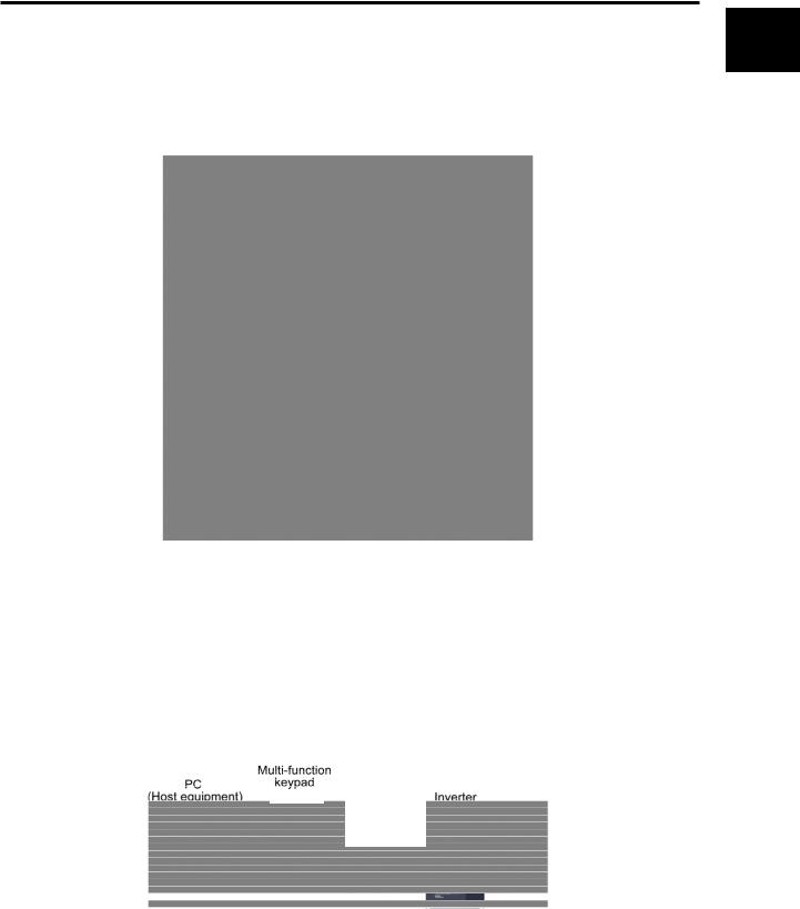
||
5.2 |
Overview of FRENIC Loader......................................................................................................................... |
5-6 |
||
5.2.1 |
Specifications ............................................................................................................................................ |
5-6 |
||
5.2.2 |
Connection ................................................................................................................................................ |
5-7 |
||
5.2.3 |
Function overview..................................................................................................................................... |
5-7 |
||
|
5.2.3.1 Setting of function code .................................................................................................................... |
5-7 |
||
|
5.2.3.2 |
Multi-monitor.................................................................................................................................... |
5-8 |
|
|
5.2.3.3 |
Running status monitor ..................................................................................................................... |
5-9 |
|
|
5.2.3.4 |
Test-running .................................................................................................................................... |
5-10 |
|
|
5.2.3.5 Real-time trace—Displaying running status of an inverter in waveforms ...................................... |
5-11 |
||
Part 3 Peripheral Equipment and Options
Chapter 6 SELECTING PERIPHERAL EQUIPMENT
6.1 |
Configuring the FRENIC-Eco ........................................................................................................................ |
6-1 |
|
6.2 |
Selecting Wires and Crimp Terminals............................................................................................................. |
6-2 |
|
6.2.1 |
Recommended wires ................................................................................................................................. |
6-4 |
|
6.3 |
Peripheral Equipment ..................................................................................................................................... |
6-8 |
|
6.4 |
Selecting Options.......................................................................................................................................... |
6-14 |
|
6.4.1 |
Peripheral equipment options.................................................................................................................. |
6-14 |
|
6.4.2 Options for operation and communications ............................................................................................ |
6-21 |
||
6.4.3 Extended installation kit options ............................................................................................................. |
6-29 |
||
6.4.4 |
Meter options .......................................................................................................................................... |
6-31 |
|
|
|
Part 4 Selecting Optimal Inverter Model |
|
|
|
||
Chapter 7 SELECTING OPTIMAL MOTOR AND INVERTER CAPACITIES |
|
||
7.1 |
Selecting Motors and Inverters ....................................................................................................................... |
7-1 |
|
7.1.1 Motor output torque characteristics........................................................................................................... |
7-1 |
||
7.1.2 |
Selection procedure................................................................................................................................... |
7-3 |
|
7.1.3 |
Equations for selections ............................................................................................................................ |
7-6 |
|
|
7.1.3.1 Load torque during constant speed running ...................................................................................... |
7-6 |
|
|
7.1.3.2 Acceleration and deceleration time calculation................................................................................. |
7-7 |
|
|
7.1.3.3 Heat energy calculation of braking resistor..................................................................................... |
7-10 |
|
ix

Part 5 Specifications and Troubleshooting
Chapter 8 SPECIFICATIONS
8.1 |
Standard Models ............................................................................................................................................. |
8-1 |
||
8.1.1 |
Three-phase 208V ..................................................................................................................................... |
8-1 |
||
8.1.2 |
Three-phase 460 V .................................................................................................................................... |
8-2 |
||
8.2 |
Common Specifications.................................................................................................................................. |
8-4 |
||
8.3 |
Terminal Specifications .................................................................................................................................. |
8-7 |
||
8.3.1 |
Terminal functions .................................................................................................................................... |
8-7 |
||
8.3.2 |
Terminal arrangement diagram and screw specifications........................................................................ |
8-18 |
||
|
8.3.2.1 |
Main circuit terminals ..................................................................................................................... |
8-18 |
|
|
8.3.2.2 |
Control circuit terminals.................................................................................................................. |
8-20 |
|
8.4 |
Operating Environment and Storage Environment ....................................................................................... |
8-21 |
||
8.4.1 |
Operating environment............................................................................................................................ |
8-21 |
||
8.4.2 |
Storage environment ............................................................................................................................... |
8-22 |
||
|
8.4.2.1 |
Temporary storage........................................................................................................................... |
8-22 |
|
|
8.4.2.2 |
Long-term storage ........................................................................................................................... |
8-22 |
|
8.5 |
External Dimensions..................................................................................................................................... |
8-23 |
||
8.5.1 |
Standard models ...................................................................................................................................... |
8-23 |
||
8.5.2 |
DC reactor............................................................................................................................................... |
8-26 |
||
8.5.3 |
Multi-function Keypad............................................................................................................................ |
8-27 |
||
8.6 |
Connection Diagrams ................................................................................................................................... |
8-28 |
||
8.6.1 |
Running the inverter with keypad ........................................................................................................... |
8-28 |
||
8.6.2 |
Running the inverter by terminal commands .......................................................................................... |
8-29 |
||
8.7 |
Protective Functions ..................................................................................................................................... |
8-31 |
||
Chapter 9 FUNCTION CODES |
|
|||
9.1 |
Function Code Tables ..................................................................................................................................... |
9-1 |
||
9.2 |
Overview of Function Codes ........................................................................................................................ |
9-23 |
||
9.2.1 |
F codes (Fundamental functions) ............................................................................................................ |
9-23 |
||
9.2.2 |
E codes (Extension terminal functions)................................................................................................... |
9-52 |
||
9.2.3 |
C codes (Control functions of frequency) ............................................................................................... |
9-91 |
||
9.2.4 |
P codes (Motor parameters) .................................................................................................................... |
9-95 |
||
9.2.5 |
H codes (High performance functions) ................................................................................................... |
9-98 |
||
9.2.6 |
J codes (Application functions)............................................................................................................. |
9-120 |
||
9.2.7 |
y codes (Link functions)........................................................................................................................ |
9-131 |
||
Chapter 10 TROUBLESHOOTING |
|
|||
10.1 Before Proceeding with Troubleshooting ..................................................................................................... |
10-1 |
|||
10.2 If No Alarm Code Appears on the LED Monitor.......................................................................................... |
10-2 |
|||
10.2.1 |
Motor is running abnormally................................................................................................................... |
10-2 |
||
10.2.2 |
Problems with inverter settings ............................................................................................................... |
10-7 |
||
10.3 If an Alarm Code Appears on the LED Monitor........................................................................................... |
10-8 |
|||
10.4 If an Abnormal Pattern Appears on the LED Monitor while No Alarm Code is Displayed........................ |
10-19 |
|||
x

Appendices
App.A Advantageous Use of Inverters (Notes on electrical noise)......................................................................... |
A-1 |
|
A.1 |
Effect of inverters on other devices ............................................................................................................. |
A-1 |
A.2 |
Noise............................................................................................................................................................ |
A-2 |
A.3 |
Noise prevention.......................................................................................................................................... |
A-4 |
App.B |
Japanese Guideline for Suppressing Harmonics by Customers Receiving High Voltage or |
A-12 |
B.1 |
Special High Voltage ................................................................................................................................. |
|
Application to general-purpose inverters................................................................................................... |
A-12 |
|
B.2 |
Compliance to the harmonic suppression for customers receiving high voltage or |
A-13 |
|
special high voltage ................................................................................................................................... |
|
App.C |
Effect on Insulation of General-purpose Motors Driven with 460V Class Inverters................................. |
A-17 |
C.1 |
Generating mechanism of surge voltages .................................................................................................. |
A-17 |
C.2 |
Effect of surge voltages ............................................................................................................................. |
A-18 |
C.3 |
Countermeasures against surge voltages ................................................................................................... |
A-18 |
C.4 |
Regarding existing equipment ................................................................................................................... |
A-19 |
App.D Inverter Generating Loss ........................................................................................................................... |
A-20 |
|
App.E |
Conversion from SI Units.......................................................................................................................... |
A-21 |
App.F |
Allowable Current of Insulated Wires ....................................................................................................... |
A-23 |
Glossary
xi

Part 1 General Information
Chapter 1 INTRODUCTION TO FRENIC-Eco
Chapter 2 PARTS NAMES AND FUNCTIONS
Chapter 3 OPERATION USING THE MULTI-FUNCTION KEYPAD

Chapter 1
INTRODUCTION TO FRENIC-Eco
This chapter describes the features and control system of the FRENIC-Eco series and the recommended configuration for the inverter and peripheral equipment.
|
|
Contents |
1.1 |
Features............................................................................................................................................................. |
1-1 |
1.2 |
Control System................................................................................................................................................ |
1-18 |
1.3 |
Recommended Configuration ......................................................................................................................... |
1-19 |

1.1 Features
1.1 Features
Default functions for fans and pumps
Switching motor power between commercial lines and inverter outputs
The FRENIC-Eco series of inverters is equipped with built-in sequence control logic that supports starting of the motor via the commercial lines by using an external sequence and switches the motor power between commercial lines and inverter outputs. This feature simplifies the user’s power control system configuration.
In addition to this Fuji’s standard switching sequence, an auto-switching sequence is also available upon occurrence of an inverter alarm.
The schematic diagram below shows a typical sequence control circuit externally configured for an effective application of the sequence control logic.
GFCI or
MCCB
Refer to function codes E01 to E05 in Section 9.2.2 "E codes" and J22 in Section 9.2.6 "J codes."
Full PID control functions
The PID control has the "slow flowrate stop" and "deviation alarm/absolute value alarm output" functions. It also supports a variety of manual speed (frequency) commands to make a balance-less and bump-less switching available that automatically adjusts the output frequency against the frequency command.
Further, the PID control has an anti-reset wind-up function for prevention of overshooting, as well as supporting PID output limiter and integration hold/reset signals, facilitating the adjustment necessary for PID control.
Refer to the PID Frequency Command Generator in Section 4.8, function codes E01 to E05, E20 to E22, E24, and E27 in Section 9.2.2 "E codes," and J01 to J06, J10 to J13, and J15 to J19 in Section 9.2.6 "J codes."
1-1
Eco-FRENIC ABOUT 1 .Chap

Slow flowrate stop function
A new function called slow flowrate stop is now added to the low limiter for securing the minimum operation speed of a fan and pump, etc., whereby the operation will stop if the flowrate drops and remains below the low limit for a certain length of time. This, combined with PID control, contributes to more energy-saving operation.
Refer to function codes E20 to E22, E24, and E27 in Section 9.2.2 "E codes" and J15, J16, and J17 in Section 9.2.6 "J codes."
Command loss detection
The analog frequency command is monitored and when an abnormal condition is detected, an alarm signal is output. Further, if in a critical system such as an air conditioner for an important facility, an abnormal condition is detected in the circuit handling the analog frequency command source, the system will be stopped or will continue its operation at the specified speed (at the specified percentage of the command just before the detection of the abnormal condition).
Refer to function codes E20 to E22, E24, E27, and E65 in Section 9.2.2 "E codes."
1-2
1.1 Features
Low output torque detection
A low output torque detection signal is asserted in the event of sudden decrease in torque as a result of an abnormal condition such as the belt being broken between the motor and the load (e.g., a belt-driven fan). This signal, which indicates abnormal conditions occurring in the facility (load), can therefore be used as maintenance information.
Refer to function codes E20 to E22, E24, E27, E80 and E81 in Section 9.2.2 "E codes."
Continuous operation at momentary power failure
You can choose either tripping or automatic restart in the event of a momentary power failure. You can choose starting at the frequency at the momentary power failure occurrence or starting at 0 Hz, according to the requirement. Further, you can choose a control mode to prolong the running time utilizing the kinetic energy due to the load’s moment of inertia during the momentary power failure.
Eco-FRENIC ABOUT 1 .Chap
Inverter: FRN007F1S-2U
Motor: 7HP
Refer to function code F14 in Section 9.2.1 "F codes."
1-3

Switching between remote and local modes
You can choose a mode of inverter operation between remote (communications link or terminal commands) and local (keypad in any location such as built-in or on the panel) for both run commands and frequency commands, with combination sets of frequency command 1 and frequency command 2, run command 1 and run command 2.
Refer to Running/stopping the motor in Section 3.2.1 and function codes F01 and F02 in Section
9.2.1"F codes."
Auto search for idling motor's speed
The auto search feature helps the idling motor start smoothly, by setting an auto search frequency. When the motor is in idling state due to natural convection, momentary power failure or other similar situations, the inverter can automatically search for the current motor speed and direction and start/restart the motor smoothly from the frequency that can be harmonized with the current motor speed and rotation, without stopping it. For restart after a recovery from the momentary power failure, you have a choice of two frequencies--the frequency saved at the power failure and the starting frequency.
Refer to function codes H09 and H17 in Section 9.2.5 "H codes."
1-4

1.1 Features
Choosing from a variety of frequency command sources
A variety of frequency command sources are provided to match your power system as listed below.
• Keypad ( /
/  keys)
keys)
The keypad allows you to set a frequency command as an output frequency, motor speed, load shaft speed, percentage to the maximum frequency, etc.
• Analog terminal inputs
You can set up analog inputs with the following signals, either individually or in combination of them.
-4 to 20 mA DC [C1] or 0 to 10 VDC [12]
-Inverse of the above signals
-Voltage input terminal for analog setting [V2] (built-in)
•Multistep frequency (8 steps)
•UP/DOWN operation
•Switching between frequency commands 1 and 2
•Suitable manipulation (addition) of frequencies, available by using auxiliary frequency commands 1 and 2
•RS-485 communications link facility supported as standard
•Switching between remote and local modes
Refer to function code F01 in Section 9.2.1 "F codes," E01 to E05 and E61 to E63 in Section 9.2.2 "E codes," and H30 in Section 9.2.5 "H codes."
Eco-FRENIC ABOUT 1 .Chap
1-5

Monitor for analog input
The inverter is equipped with input terminals for accepting analog signals from the outside equipment or the motor. By connecting the outputs of a flow meter, a pressure gauge, or any other sensor, you can display them on the LED monitor on the keypad that shows their physical values in easy-to-understand analog values (multiplied with a specified coefficient in some cases). It is also possible to build a host-controlled system by sending/receiving such information via the communications link to/from a host computer.
Refer to function codes E43, E45, and E48 in Section 9.2.2 "E codes."
1-6
1.1 Features
Contribution to energy-saving
Automatic energy-saving (standard feature)
A new, automatic energy-saving function is included as a standard feature, which controls the system to minimize the total loss (motor loss plus inverter loss), rather than just the motor loss as in the predecessor models. This feature thus contributes to further energy saving in applications with fans and pumps.
Figure 1.1 Example of Energy-Saving
Refer to the Drive Command Controller in Section 4.7 and function codes F09 and F37 in Section
9.2.1"F codes."
Monitoring electric power
In addition to electric power monitoring on the multi-function keypad, online monitoring is available from the host equipment through the communications link.
This function monitors real-time power consumption, cumulative power consumption in watt-hours, and cumulative power consumption with a specified coefficient (such as an electricity charge).
Refer to Chapter 3 "OPERATION USING THE MULTI-FUNCTION KEYPAD" and Chapter 5 "RUNNING THROUGH RS-485 COMMUNICATION."
1-7
Eco-FRENIC ABOUT 1 .Chap

PID control supported
PID control, which is a standard feature on the inverter, allows you to control temperature, pressure, and flowrate without using any external adjustment devices so that you can configure a temperature control system without an external thermal conditioner.
Refer to the PID Frequency Command Generator in Section 4.8 and function codes J01 to J06 in Section 9.2.6 "J codes."
Cooling fan ON/OFF control
The inverter's cooling fan can be stopped whenever the inverter does not output power. This contributes to noise reduction, longer service life, and energy saving.
Refer to function codes E20 to E22, E24, and E27 in Section 9.2.2 "E codes" and H06 in Section 9.2.5 "H codes."
1-8

1.1 Features
Consideration for surrounding environment
Reactor built-in type added to standard line-up
A DC reactor for power-factor correction is now integrated in the inverter (for the range of 1 to 60 HP for 208 V, 1 to 75 HP for 460 V). In addition, a zero-phase reactor (ferrite ring) and a capacitive filter are integrated in the inverters of 25 HP for 208 V, 30 HP for 460 V or below. These features simplify the power-related wiring (no need for DC reactor and capacitive filter wiring). The new good-shortcut wiring feature also fully covers Standard Specifications for Public Building Construction set by the Japanese Ministry of Land, Infrastructure and Transport (Volume for Electric Facilities and Volume for Mechanical Facilities).
Eco-FRENIC ABOUT 1 .Chap
(*) for models with capacity of
25 HP for 208 V, 30 HP for 460 V or below
Refer to Chapter 6 "SELECTING PERIPHERAL EQUIPMENT."
Inrush current suppression circuit integrated in all models
An inrush current suppression circuit is integrated as standard in all models, therefore the cost of peripheral devices such as magnetic contactor (MC) can be reduced.
EMC-filter built-in type added to semi-standard line-up
The product can be used to fully comply with the EMC Directives in EU. (15 HP for 208 V, 20 HP for 460 V or below)
Standard installation of input terminals for auxiliary control power of all models
The auxiliary control input terminals provide a convenient shortcut for automatic input power source switching between commercial line and inverter as standard terminals.
Refer to Section 8.3 "Terminal Specifications."
Various functions for protection and easy maintenance
FRENIC-Eco series features the following facilities useful for maintenance.
Refer to Chapter 3 "OPERATION USING THE MULTI-FUNCTION KEYPAD" in this manual and the "FRENIC-Eco Instruction Manual", Chapter 7 "MAINTENANCE AND INSPECTION."
Lifetime estimation for DC link bus capacitors (reservoir capacitors)
This function shows the lifetime of the DC link bus capacitor as a ratio to its initial capacitance value, helping you determine the replacement timing of the capacitor. (Design life of DC link bus capacitors: 10 years under these conditions: load = 80% of inverter's rated current; ambient temperature = 40°C (104°F))
Long-life fans
Use of a long-life fan reduces replacement work. (Design life of fans: 10 years for models of 30 HP for 208 V, 40 HP for 460 V or below; 7 years for models of 40 HP for 208 V, 50 HP for 460 V or above, at ambient temperature of 40°C (104°F))
1-9

Easy to replace cooling fans
On 7 to 30 HP for 208 V, 7 to 40 HP for 460 V models, you can easily replace the cooling fan in simple steps, since it is mounted on the upper part of the inverter. On models of 40 HP for 208 V, 50 HP for 460 V or above, you can replace it easily from the front side without detaching the inverter from your panel.
To replace the cooling fan, follow the procedures as shown below.
<FRN015F1S-2U>
<FRN050F1S-2U>
1-10

1.1 Features
Cumulative running hours of inverter, capacitor, cooling fan, and motor
FRENIC-Eco series accumulates running hours of the inverter itself, motor (mechanical system), cooling fan, and electrolytic capacitor on the printed circuit board for recording and displaying on the keypad.
These data can be transferred to host equipment via the communications link and used for monitoring and maintenance for mechanical system to increase the reliability of the facility or plant (load).
Outputting a lifetime early warning signal to the programmable transistor
When either one of the DC link bus capacitor (reservoir capacitor), the electrolytic capacitors on the printed circuit boards, and the cooling fans is nearing the end of its lifetime, a lifetime early warning signal is output.
Refer to function codes E20 to E22, E24, and E27 in Section 9.2.2 "E codes."
Record of the 4 latest alarm history available
You can view alarm codes and their related information up to four latest ones.
Refer to Section 3.3.7 "Reading alarm information."
Protective function against phase loss in input/output
Protection against phase loss in input/output circuits is possible at start-up and during operation.
Refer to the Protective Functions in Section 8.7 and function code H98 in Section 9.2.5 "H codes."
Protective function for grounding fault
Protection is provided for an overcurrent caused by a grounding fault.
Refer to the Protective Functions in Section 8.7.
1-11
Eco-FRENIC ABOUT 1 .Chap

Protection of motor with PTC thermistor
By connecting the Positive Temperature Coefficient (PTC) thermistor embedded in the motor to the terminal [V2], you can monitor the temperature of the motor, and stop the inverter output before the motor overheats, thereby protecting the motor. You can select the action in the event of an overheat hazard according to the PTC protection level: whether to stop the inverter (alarm stop) or to turn ON the alarm output signal on the programmed terminal.
Refer to function codes F10 to F12 in Section 9.2.1 "F codes" and H26 and H27 in Section 9.2.5 "H codes."
1-12
 Loading...