


 Loading...
M ICR O-CO NTROLLER X
Type : PXF -2
O peration M nual
INP-TN5 A2400a-E

PLEASE READ FIRST
Please read the section “Safety Warnings” thoroughly before using. Safety precautions must be taken by every user to prevent accidents. Failure to comply with the instructions contained in this manual may reduce the safety of the instrument.
The safety requirements are classified into “Warning” and “Caution” according to the following interpretations:
 WARNING
 CAUTION
Mishandling may lead to serious injury or death.
Mishandling may result in personal injury or damage to the property.
1

 WARNING
Installation and wiring
►This equipment is intended to be used under the following conditions.
Ambient temperature |
-10 to 50°C |
|
|
Operating humidity |
90%RH or less (Non condensation) |
|
|
Installation category: |
II |
According to IEC 61010-1 |
|
Pollution degree: |
2 |
||
|
|||
Recommended fuse |
250V AC, 0.1A T(Time-Lag) (AC100~240V) |
||
|
400V DC/400V AC, 1A T(Time-Lag) (DC/AC24V) |
||
Usage environment |
Indoor use |
|
|
►If accessible Safety Extra Low Voltage (SELV) circuits are to be connected to Signal input terminal, SSR drive output terminal, Current output terminal or Communication (RS485) terminal, ensure to provide a basic insulation between the SELV circuits and these terminals. For example, use transformer which has a basic insulation or higher degree of insulation.
If accessible Safety Extra Low Voltage (SELV) circuits are to be connected to Communication (RS-485) terminal, be sure to provide a basic insulation between these terminals.
For example, use a RS-485/232 converter which has a basic insulation.
The basic insulation requires a clearance at least 1.5 mm and a creepage of at least 3.0 mm.
Failure to maintain these minimum distances would invalidate the UL61010/EN61010 safety approval.
►For 24V DC/AC power supply model, if the equipment is connected to the Safety Extra Low Voltage (SELV) circuit, a basic insulation must be provided between the SELV circuit and the power input terminals. Otherwise, the power input terminals must be connect to Extra Low Voltage (ELV) circuit so as to prevent the electric shock.
►For CT input, use Current Transfer which has specification as shown below in order to prevent the electric shock and spread of fire.
1) |
Over Voltage Category |
II |
|
2) |
Pollution Degree |
2 |
|
3) |
Required level of Insulating |
BASIC INSULATION, SUPPLYMENTARY INSULATION, or |
|
REINFORCED INSULATION |
|||
|
|
||
4) |
Maximum Voltage line to neutral |
300Vac rms or 300Vdc |
2

About safety standard
Please observe the following instructions to meet the requirements of safety standard. Failure to observe these instructions violates safety standards.
(This product is not safety equipment.)
●Install a recommended fuse, which is specified in the instruction manual, between the external main power (Mains Circuit) and this equipment.
●Do not connect SELV directly to Signal input terminal, SSR Drive output terminal, Current output terminal, or Communication (RS-485) terminal. Otherwise, it may result in electrical shock.
If accessible Safety Extra Low Voltage (SELV) circuits are to be connected to Signal input terminal, SSR Drive output terminal, Current output terminal or Communication (RS-485) terminal, ensure to provide a basic insulation between the SELV circuits and these terminals. For example, use transformer which has a basic insulation or higher degree of insulation.
If accessible Safety Extra Low Voltage (SELV) circuits are to be connected to Communication (RS-485) terminal, be sure to provide a basic insulation between these terminals
For example, use a RS-485/232 converter which has a basic insulation.
The basic insulation requires a clearance at least 1.5 mm and a creepage of at least 3.0 mm.
●Be sure to install an appropriate external protective circuit to prevent excessive temperature rise etc.
●When performing wiring work, be sure to turn the power off and to wear protection gloves or safety glasses, to prevent an electric shock.
●Set proper parameter input signals which correspond to each input to be connected. Be careful not to confuse voltage input with current input, or vice versa.
●Do not use this equipment for the measurement of circuits which falls under measurement categories II, III, or IV.
●Do not use this equipment for measurement of signals to which a voltage over 30 Vr.m.s. or over 60 V DC is applied.
●Be sure to use terminal covers. Before removing a terminal cover, turn off all the power.
►For the above, if voltage exceeds 50Vdc (called danger voltage), grounding and basic insulation for all terminals of the equipment and auxiliary insulation for DO outputs are required.
Note that the insulation class for this equipment is as follows. Before installing, please confirm that the insulation class for equipment meets usage requirements.
Type PXF4
3

Type PXF5/9
●In cases where damage or problems with this equipment may lead to serious accidents, install appropriate external protective circuits.
●As this equipment does not have a power switch or fuses, install them separately as necessary. If you install a fuse, be sure to place it between the main power switch and this equipment.
(Main power switch: 2-point Breaker, fuse rating: 250V 1A)
●A power switch or a circuit breaker should be installed within the power supply facility.
●A power switch or a circuit breaker should be properly installed within easy reach of an operator.
●A power switch or a circuit breaker should be identified as the one for this product.
●Electrical wiring must be made by the qualified personnel only and in accordance with your local and national standards.
●For power supply wiring, use wire equal to 600V vinyl insulation or above.
●To prevent damage and failure of the equipment, provide the rated power voltage.
●To prevent shock and equipment failure, do not turn the power ON until all wiring is complete.
●Before feeding power, confirm that clearance space has been secured to prevent shock and fire with the equipment.
●Do not touch the terminal while the machine is on. Doing so risks shock or equipment errors.
●Never disassemble, convert, modify or repair this equipment. Doing so carries the risk of abnormal operation, shock and fire.
●Output relays has limited-life. The contact of output relay may stay ON or OFF when it reaches the end of its service life. Be sure to provide an external protective circuit for safety.
●The factory default setting of this equipment is as follows. Change the setting as necessary so as the equipment to meet your application.
Please note that the improper settings may result in overheat or unexpected damage. For the details of operation, read this manual.
Control output 1: heating control
Control output 2 (optional): cooling control Digital input 1 to 5 (optional): no function
●Symbols on the equipment
Please read this instruction manual thoroughly, and use the product accordingly.
Maintenance
●When installing and removing the equipment, turn the power OFF. Failing to do so may cause shock operational errors or failures.
●Periodic maintenance is recommended for continuous and safe use of this equipment.
●Some components used on this equipment have a limited life and/or may deteriorate over time.
●The warranty period for this unit (including accessories) is three year after the date of manufacture, if the product is used properly.
4

 CAUTION
Cautions on installation
Avoid the following places for installation:
●A place where the ambient temperature may reach beyond the range of from 0 to 50°C while in operation.
●A place with rapid temperature changes, leading to dew condensation
●A place where corrosive gases (sulfide gas and ammonia gas, in particular) or combustible gases are emitted.
●A place with vibration or shock directly. (Vibration and shock may cause output relay malfunction.)
●A place exposed to water, oil, chemicals, steam and/or vapor.
(If the equipment gets wet, there is a risk of electric shock or fire, so have it inspected by the distributor.)
●A place where the unit is exposed to dust, salt air, or air containing iron particles.
●A place where the unit is subject to interference with static electricity, magnetism, and noise.
●A place where the unit is exposed to direct sunlight.
●A place where the heat may be accumulated due to the radiation of heat. Recommended site condition:
●A place where the ambient humidity during operation is between 45 to 85%RH.
About EMC standard
●This equipment is designed as Class A (for industrial environment). Do not use this equipment in home environment, or it may cause electric jamming. If you use this equipment in home environment, install appropriate measures on the outside of the equipment.
●Under the requirement of EMC standard, the maximum length of a sensor to be connected to this equipment is 30 m. Do not connect the sensor longer than 30 m.
Caution on installation on panel
●Attach the included Fixtures (2 pieces) onto the top and bottom of PXF5/9 , and tighten them with a screwdriver. The clamp torque is approx. 0.15 N·m (1.5 kg·cm) The plastic fixture is designed such that over tightening will cause left/right cracking to the central area of the Fixtures and hence reduce the torque. Cracking to the central area will not cause any problems in terms of usability of the equipment as is.
(However, do exercise caution in not applying too much torque because the casing is made of plastic.)
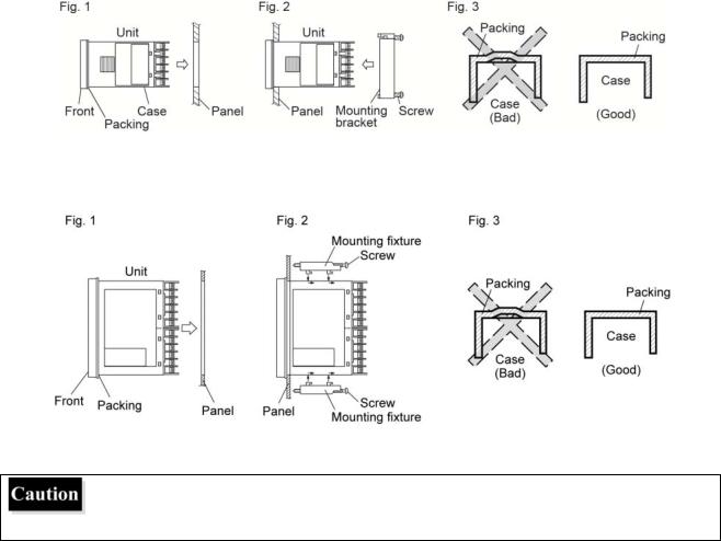
● The front of this equipment is waterproof in compliance with NEMA-4X standards (IP66-equivalent). However, regarding waterproofing between the equipment and the panel, use the included packing to ensure waterproofing and attach it according to the guidelines below. (Incorrect attachment may cause the equipment to lose its waterproof capabilities.)
(1)As shown in Fig. 1, insert the panel after attaching the packing to the equipment case.
(2)As shown in Fig. 2, tighten the fixture screws so that no gaps can remain between the equipment face, the packing and the panels. Once finished, confirm that there are no changes in shape such as displaced or improperly-fitted packing, etc. as shown in Fig. 3.
●Please exercise caution if the panel strength is weak and gaps develop between the packing and the panel, as this will result in the loss of its waterproofing capabilities.
5
PXF4
Mounting on vertical plane (in horizontal position)
PXF5/9
Mounting on vertical plane (in horizontal position)
●In order not to hamper heat radiation, do not block the sides of the equipment.
●Do not block the air vents on the upper part of the terminal.
●For PXF9, please attach the Fixtures to the attachment holes in the center of the main unit.
Cautions on wiring
●For thermocouple input, use the designated compensation lead; for resistance temperature sensors, use wires with small lead wire resistance and without any resistance difference among the three wires.
●To avoid noise conductor effects, do not use input signal wires in close proximity with electric power lines or load lines.
●Use the input signal lines and output signal lines that are separated from each other and are shielded.
●If there is a lot of noise from the power source, adding an insulation transducer and using a noise filter is recommended. Always attach a noise filter to a panel that is grounded securely, and keep the wiring between the noise filter output side and the measuring equipment power terminal wiring to a minimum length. Please do not attach fuses and switches, etc. to the noise filter output wiring since doing so will decrease the filter’s effectiveness.
●Twisting the measuring instrument wiring is effective when connecting the wires. (The shorter the pitch of the twist, the more effective the connection is against noise.)
●When the power is turned on, it takes some time before a contact output starts operation. If using it as a signal to an external interlock circuit, please couple it with a delayed relay.
Concerning the output relay, connecting the maximum rated load will shorten the relay’s life; so please attach an auxiliary relay. If the output operation frequency is high, selecting a SSR drive output type is recommended. [Proportional cycles] Relay output: 30 seconds or more, SSR drive output: 1 second or more
6

PXF5/9 |
PXF4 |
●When inductive loads such as magnetic opening/closing equipment, etc. as relay output equipment are connected, use of a serge absorber is recommended in order to protect the connection points against opening/closing surges and to ensure long-term use.
Recommended specification for surge absorber
Voltage |
Nominal varistor voltage |
100 V |
240 V |
200 V |
470 V |
Key Operation Cautions/Error Operations
●The alarm function does not work properly when an error takes place unless the settings are made correctly. Always verify its setting before operation.
●If the input wiring breaks, the display will read "UUUU" or "LLLL". When replacing the sensor, always turn the power OFF.
Others
●Do not wipe the equipment with organic solvents such as alcohol or benzene, etc. If wiping is necessary, use a neutral cleaning agent.
●Do not use mobile phones near the instrument (within 50 cm). Otherwise malfunction may occur.
●Trouble may occur if the equipment is used near a radio, TV, or wireless device.
●Do not turn off the power right after you change the setting. If you turn off the power after setting change, be sure to wait for a few seconds before turning it off, so that the changed values can be stored on the nonvolatile memory.
7

C nten ts
PL EASE RE D FIRST ······························ ·····················································1 C ntents····· ············································ ·····················································8 Fo r Proper U se ········································ ·····················································9 M odel Specifications ································· ··················································· 10
1Part nam es and functions····· ···························································14
1-1 Digital characters ···························· ··················································· 18
2Basic Op eration ················· ···························································19
2-1 |
Basic operation ······························· ··················································· 19 |
2-2 |
Chang ing SV (se value) ··················· ··················································· 20 |
2-3 |
Param eters List······························· ··················································· 21 |
3 Parameter function and setti ng proced ure ··········································29
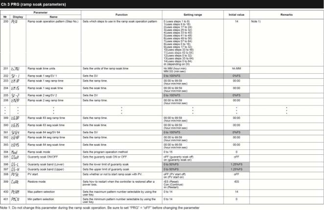
3-1 Operation mode ······························ ··················································· 29 3-2 CH1 P ID (Control parameters) ··········· ··················································· 41 3-3 CH2 P LT (PID palette parameters)······ ··················································· 57 3-4 CH3 P RG (Ramp soak para meters) ···· ··················································· 70 3-5 CH4 M ON (Monitor parameters)········· ··················································· 82
3-6 |
CH5 ALM (Alarm parameter ) ············ ················································· 100 |
||
3-7 |
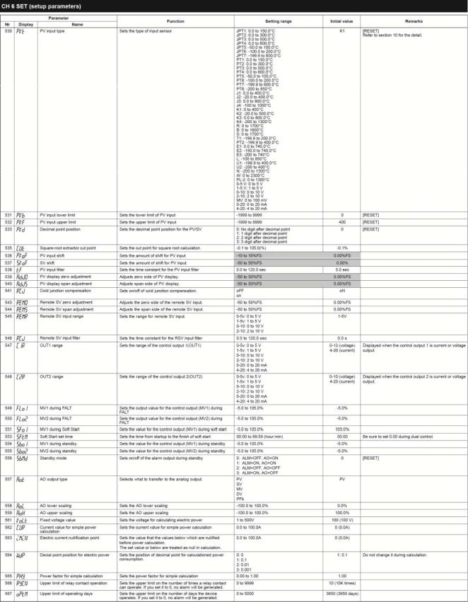
CH6 S ET (Setup parameters ) ············ ··················································114 |
||
3-8 |
CH7 S YS (Syste m paramete rs)·········· ················································· 141 |
||
3-9 |
CH8 M ATH (Calculation par meters)··· ················································· 162 |
||
3-10 |
CH9 COM (Com munication parameters) ············································· 166 |
||
3-11 |
CH1 |
PFB (PFB parameter) ············ ················································· 176 |
|
3-12 |
CH11 DSP (Par ameter mas k)··········· ················································· 182 |
||
3-13 |
CH1 |
CFG (Con figuration arameters ) ··············································· 183 |
|
3-14 |
CH1 |
PASS (Password parameters)·· ················································· 195 |
|
4 TROUBL ESHOOTI NG ········ ························································· 197
8

For Proper Use
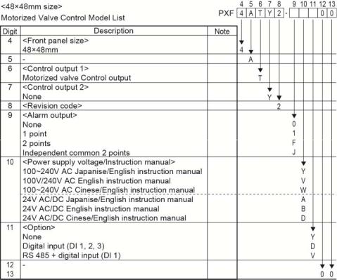
Confirmation of model |
Please confirm that the model delivered matches your order. |
code |
"Model Specifications" (page 10) |
|
|
Installation and Mounting |
External dimensions |
|
•Panel cutout |
|
• Panel mounting dimensions |
|
"3 Installation and Mounting" (instruction manual) |
|
|
Wiring |
Terminal connection diagram |
|
"4 Wiring" (instruction manual) |
|
|
Power ON |
|
|
|
Display and Operations |
Changing set value |
Parameters List |
Basic operations |
Functions of the |
Parameters List |
Temperature Controller |
Parameter setting |
|
"2-1 Basic operation" (page 19) |
|
"2-2 Changing SV (set value)" (page 20) |
|
"3-2 CH1 PID (Control parameters) " (page 41) |
|
|
Advanced Usage |
Setting of input sensor and input range |
|
Selecting control method |
|
Controlling through auto-tuning |
|
Parameter setting |
|
"3-7 CH6 SET (Setup parameters)" (page 114) |
|
"3-2 CH1 PID (Control parameters)" (page 41) |
|
"AT Auto tuning (005)" (page 33 |
|
"(4) Self tuning control (SELF) (3) Fuzzy control (FUZY)" (page 151) |
|
|
Operation |
|
|
|
Error Indications |
Display during equipment error |
|
"4 TROUBLESHOOTING" (page 197) |
Wait 30 minutes for the controller to be stabilized thermally. Operations such as measurements should be started after the equipment has been energized at least for 30 minutes.
9
Model Specifications
<PXF4>
10
11

<PXF5/9>
12

13
1 Part names and functions
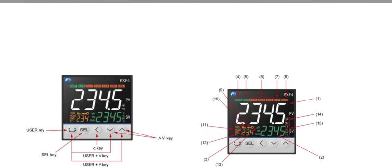
This section describes the names and functions of each part of the front panel. The front panel has the PV and SV displays, the status indicator lamps, and the setting keys, etc. Their functions are explained below. Please read and understand them before using the PXF.
For details about the setting of parameters, see Chapter 2.
PXF4
Operation keys |
Indicators |
USER key
•Press this key once in PV/SV display to switch between SV display and MV display.
•Press and hold this key in PV/SV display to start the assigned function. (No function is allocated at the factory.)
•Press this key once in operation control mode, channelselection mode, or setup mode to return to PV/SV display.
SEL key
•Press this key once in PV/SV display to move to operation control mode.
•Press and hold this key in setup mode to move to channel selection mode.
•Press this key once in channel selection mode to move to setup mode.
•Press and hold this key in setup mode to move to channel selection mode.
•Press this key once in parameter selection submode of setup mode to enter parameter editing submode.
•Press this key once in parameter editing submode to save the change and return to parameter selection submode.
< key
•Use the this key to select the digit when changing values.
˅˄ key
•Use the this key to change SV value when in PV/SV screen.
•During in operation control mode, channel selection mode, or setup mode, this key allows you to change parameters to be displayed.
•During in parameter setting mode, this key allows you to change parameter settings.
(1) Indicates process value (PV)
Shows parameter name when in parameter setting.
(2) Set point (SV)
Shows set value. Shows parameter set point when in parameter setting.
(3) Screen No.
Shows screen No. when in parameter setting.
(4) OUT1 indicator
Lights during control output 1 is ON.
(5) OUT2 indicator
Lights during control output 2 is ON.
(6) EV 1, EV 2, EV 3 indicators
Lights during digital output 1 to 3 are ON.
(7)STBY indicator
Lights during standby.
(8)MANU indicator
Lights during manual mode.
(9)Lock indicator
Lights during key lock.
(10)No. indicator
Lights during a screen No. is displayed.
(11)RUN/HOLD/END indicators
Lights during ramp/soak operation.
(12)AT indicator
Lights during auto tuning.
(13) MV indicator
Lights during MV is displayed on SV display.
(14)°C/˚F indicator
Shows the temperature unit under use.
14
USER + ˄ key
•Press and hold this key in PV/SV display to start the assigned function.
(The factory set function for this key is switching between RUN and standby.)
USER + ˅ key
•Press and hold this key in PV/SV display to start the assigned function.
(The factory set function for this key is switching between start/stop of auto-tuning.)
(15) A, %, kW/h indicator
Shows the unit being applied to values on SV display during the operation mode.
15

<PXF5/9>
Operation keys |
Indicators |
USER key
•Press this key once in PV/SV display to switch between SV display and MV display.
•Press and hold this key in PV/SV display to start the assigned function. (No function is allocated at the factory.)
•Press this key once in operation control mode, channelselection mode, or setup mode to return to PV/SV display.
SEL key
•Press this key once in PV/SV display to move to operation control mode.
•Press and hold this key in setup mode to move to channel selection mode.
•Press this key once in channel selection mode to move to setup mode.
•Press and hold this key in setup mode to move to channel selection mode.
•Press this key once in parameter selection submode of setup mode to enter parameter editing submode.
•Press this key once in parameter editing submode to save the change and return to parameter selection submode.
< key
• Use the this key to select the digit when changing values.
˅˄ key
•Use the this key to change SV value when in PV/SV screen.
•During in operation control mode, channel selection mode, or setup mode, this key allows you to change parameters to be displayed.
•During in parameter setting mode, this key allows you to change parameter settings.
(1) Indicates process value (PV)
Shows parameter name when in parameter setting.
(2) Set point (SV)
Shows set value. Shows parameter set point when in parameter setting.
(3) Screen No.
Shows screen No. when in parameter setting.
(4) OUT1 indicator
Lights during control output 1 is ON.
(5) OUT2 indicator
Lights during control output 2 is ON.
(6) EV 1, EV 2, EV 3 indicators
Lights during digital output 1 to 3 are ON.
(7)STBY indicator
Lights during standby.
(8)MANU indicator
Lights during manual mode.
(9)Lock indicator
Lights during key lock.
(10)No. indicator
Lights during a screen No. is displayed.
(11)RUN/HOLD/END indicators
Lights during ramp/soak operation.
(12)AT indicator
Lights during auto tuning.
(13) MV indicator
Lights during MV is displayed on SV display.
(14) °C/˚F indicator
Shows the temperature unit under use.
16
USER + ˄ key
•Press and hold this key in PV/SV display to start the assigned function.
(The factory set function for this key is switching between RUN and standby.)
USER + ˅ key
•Press and hold this key in PV/SV display to start the assigned function.
(The factory set function for this key is switching between start/stop of auto-tuning.)
(15) A, %, kW/h indicator
Shows the unit being applied to values on SV display during the operation mode.
(16) Bar graph
Shows MV.
17
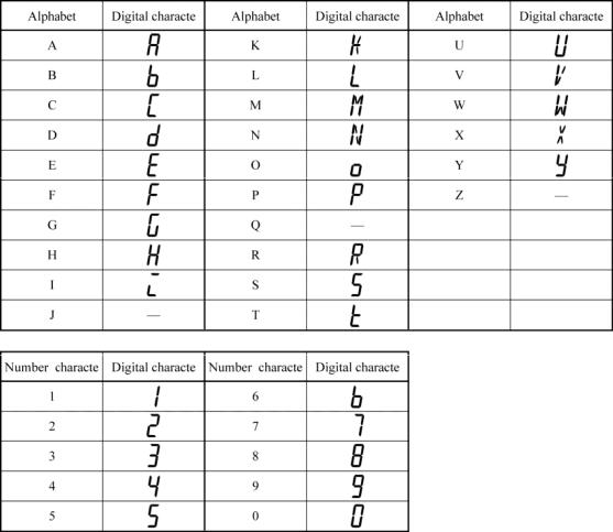
1-1 Digital characters
The f ollowing tables provide orresponde ce between digital chara cters used f or the displa y of the controller and alphanumerical characters. (See the following table for details.)
18

2 Basic Operation
2-1 Basic operation
The belo w figure ill strates the ode transition and the key operations.
Operation mode
In this m ode the nor mal operation is performed. The proc ess value (PV) and the set value (SV) are display ed. The device starts in t his mode w hen you turn on the pow er. You can hange the s et value (SV) in this mod e. You can check the output value (MV) and th e amount of electric power by switching the scre n.
Operation control mode
In this m ode you can put the device to standb y or change the alarm set value.
Channe l selection mode
In this m ode you can select the parameter ch annel to be displayed.
Setup ode
In this m ode you can setup each parameter. T his mode includes the p arameter sel ection subm ode and the paramet er editing submode, whi h can be switched by S L key. In the parameter selection submode, you can
switch between parameters by using |
˄˅ |
keys. In the para meter editin submode, y ou can chan ge parameter |
values by using ˄˅ k eys. |
1 |
|
|
|
2-2 Changing SV (set value)
[Description] _________________ ________ ________ ________ ________ ________ _____
• Th SV is a tar get value for control.
•SV must be within the range between S VL (lower limit) and SVH (upper lim it) which be long to Pid parameter.
Relat d parameters: SVL (page 50), SVH (page 50)
[Se ting example] Chan ging the S V from 250 °C to 119 5°C ____ ________ ________ _____
|
|
|
|
|
|
|
|
|
Displa |
|
|
|
Operatin g procedure |
||
|
|
|
|
1. |
|
|
|
|
|
PV |
Check that the PV/SV disp ay is shown. |
||||
|
25 0 |
SV |
|
|
Pre ss ○˄ ○˅ key to chan ge SV to “1195”. |
||
|
|
|
|
2. |
|||
|
|
|
|
||||
|
|
PV |
|
|
|||
|
119 5 |
SV |
|
3. |
Pre ss the SEL key to save the change. |
||
|
|
|
|
|
(T he change will be saved after three seconds, even if you do no t |
||
|
|
|
|
|
|||
|
|
|
|
|
pre ss any key.) |
||
|
|
|
|
|
|
|
|
20

2-3 Para meters List
The foll owing explains each channel parameter.
•The r ange of the p arameters in the shaded area indicat s the indust ial values. When you change the PV input lower limit (Pvb), PV input upper limit (P vF), or decim al place position (Pvd), reconfigure all the industrial value s.
•When the paramet er that has [RESET] on its Remarks column is c anged, turn off the pow er once, and then re-sta rt the controller.
2

22
23

24
25

26

27

28

3 P arameter functions and setti ng p oce ure
3-1 Oper ation m ode
MAN A uto/manu al switcho er (001)
[Description] ___ ________ ________ ________ ________ ________ ________ ________ ____
Manual control allo s you to set the control output to an y value.
•Rang : oFF (auto) / on(manual)
•MANU indicator lights during manual ope ration.
• In thi screen, only the switch over betwee n auto/manual is available. Manual operation o control out put is available on PV/M V screen.
Note:
This parameter is not displaye d in default setting. T o use this parameter, c hange the setting of " CH11 dSP".
[Settin g exampl e] Changin g the mod e from Auto to Manu al ______ ________ ________ ____
|
|
|
|
|
|
|
|
|
|
|
Display |
|
|
|
|
|
|
Operating procedure |
|
|
|
|
|
|
|
1. |
|
|
|
|
|
|
PV |
|
Chec k that the PV /SV display is shown. |
||||
|
250 |
|
SV |
|
|
|
|
|
|
|
|
|
|
|
|
2. |
Press the SEL ke |
to move to operation mode. |
|
|
|
|
|
|
|||||
|
|
|
|
|
|
|
|
|
|
|
|
|
PV |
|
|
3. |
|
|
|
|
oFF |
|
SV |
|
|
Press the SEL ke |
to enter M AN mode. |
||
|
|
|
|
|
|
|
(The lower part of the screen begins to blink.) |
||
|
|
|
|
|
|
|
|||
|
oN |
|
SV |
|
|
4. |
Use t he ○˄ ○˅ |
keys to change oFF to o N. |
|
|
|
|
|
||||||
|
|
|
|
|
|
||||
|
|
|
|
|
|||||
|
|
|
|
|
|
5. |
Press the SEL ke |
to save the change. |
|
|
|
|
|
|
|||||
|
|
|
|
|
|
|
|
|
|
|
|
|
PV |
|
|
|
The ode switch es from the auto mode to the manual mode. |
||
|
|
|
|
|
|
(MA NU indicato |
turns on.) |
||
|
|
|
|
|
|
|
|||
|
oN |
|
SV |
|
|
6. |
Press the key to return to the PV/SV d isplay. |
||
|
|
|
|
|
|
||||
|
|
|
|
|
|||||
|
|
|
|
|
|
|
|
|
|
2
Loading...