


 Loading...
Instruction Manual
High Performance Compact Inverter
Thank you for purchasing our FRENIC-Multi series of inverters.
•This product is designed to drive a three-phase induction motor. Read through this instruction manual and be familiar with the handling procedure for correct use.
•Improper handling might result in incorrect operation, a short life, or even a failure of this product as well as the motor.
•Deliver this manual to the end user of this product. Keep this manual in a safe place until this product is discarded.
•For how to use an optional device, refer to the instruction and installation manuals for that optional device.
Fuji Electric FA Components & Systems Co., Ltd. |
INR-SI47-1204-E |
Fuji Electric Corp. of America |
|

Copyright © 2006-2007 Fuji Electric FA Components & Systems Co., Ltd.
All rights reserved.
No part of this publication may be reproduced or copied without prior written permission from Fuji Electric FA Components & Systems Co., Ltd.
All products and company names mentioned in this manual are trademarks or registered trademarks of their respective holders.
The information contained herein is subject to change without prior notice for improvement.

Preface
Thank you for purchasing our FRENIC-Multi series of inverters.
This product is designed to drive a three-phase induction motor for fan and pump applications. Read through this instruction manual and be familiar with proper handling and operation of this product.
Improper handling might result in incorrect operation, a short life, or even a failure of this product as well as the motor.
Have this manual delivered to the end user of this product. Keep this manual in a safe place until this product is discarded.
Listed below are the other materials related to the use of the FRENIC-Multi. Read them in conjunction with this manual as necessary.
•FRENIC-Multi User's Manual
•RS-485 Communication User's Manual
The materials are subject to change without notice. Be sure to obtain the latest editions for use.
Safety precautions
Read this manual thoroughly before proceeding with installation, connections (wiring), operation, or maintenance and inspection. Ensure you have sound knowledge of the device and familiarize yourself with all safety information and precautions before proceeding to operate the inverter.
Safety precautions are classified into the following two categories in this manual.
Failure to heed the information indicated by this symbol may lead to dangerous conditions, possibly resulting in death or serious bodily injuries.
Failure to heed the information indicated by this symbol may lead to dangerous conditions, possibly resulting in minor or light bodily injuries and/or substantial property damage.
Failure to heed the information contained under the CAUTION title can also result in serious consequences. These safety precautions are of utmost importance and must be observed at all times.
Application
•FRENIC-Multi is designed to drive a three-phase induction motor. Do not use it for single-phase motors or for other purposes.
Fire or an accident could occur.
•FRENIC-Multi may not be used for a life-support system or other purposes directly related to the human safety.
•Though FRENIC-Multi is manufactured under strict quality control, install safety devices for applications where serious accidents or material losses are foreseen in relation to the failure of it.
An accident could occur.
i

Installation
•Install the inverter on a nonflammable material such as metal.
Otherwise fire could occur.
•Do not place flammable object nearby.
Doing so could cause fire.
•Do not support the inverter by its terminal block cover during transportation.
Doing so could cause a drop of the inverter and injuries.
•Prevent lint, paper fibers, sawdust, dust, metallic chips, or other foreign materials from getting into the inverter or from accumulating on the heat sink.
Otherwise, a fire or an accident might result.
•Do not install or operate an inverter that is damaged or lacking parts.
Doing so could cause fire, an accident or injuries.
•Do not get on a shipping box.
•Do not stack shipping boxes higher than the indicated information printed on those boxes.
Doing so could cause injuries.
Wiring
•When wiring the inverter to the power supply, insert a recommended molded case circuit breaker (MCCB) or residual-current-operated protective device (RCD)/a ground fault circuit interrupter (GFCI)(with overcurrent protection). Use the devices within the recommended current range.
•Use wires in the specified size.
•When wiring the inverter to the power supply that is 500 kVA or more, be sure to connect an optional DC reactor (DCR).
Otherwise, fire could occur.
•Do not use one multicore cable in order to connect several inverters with motors.
•Do not connect a surge killer to the inverter's output (secondary) circuit.
Doing so could cause fire.
•Ground the inverter in compliance with the national or local electric code.
Otherwise, electric shock could occur.
•Qualified electricians should carry out wiring.
•Be sure to perform wiring after turning the power OFF.
Otherwise, electric shock could occur.
•Be sure to perform wiring after installing the inverter body.
Otherwise, electric shock or injuries could occur.
ii

•Ensure that the number of input phases and the rated voltage of the product match the number of phases and the voltage of the AC power supply to which the product is to be connected.
Otherwise fire or an accident could occur.
•Do not connect the power supply wires to output terminals (U, V, and W).
•Do not insert a braking resistor between terminals P (+) and N (-), P1 and N (-), P (+) and P1, DB and N (-), or P1 and DB.
Doing so could cause fire or an accident.
•Generally, control signal wires are not reinforced insulation. If they accidentally touch any of live parts in the main circuit, their insulation coat may break for any reasons. In such a case, an extremely high voltage may be applied to the signal lines. Make a complete remedy to protect the signal line from contacting any hot high voltage lines.
Doing so could cause an accident or electric shock.
•Wire the three-phase motor to terminals U, V, and W of the inverter, aligning phases each other.
Otherwise injuries could occur.
•The inverter, motor and wiring generate electric noise. Take care of malfunction of the nearby sensors and devices. To prevent the motor from malfunctioning, implement noise control measures.
Otherwise an accident could occur.
Operation
•Be sure to install the terminal cover before turning the power ON. Do not remove the covers while power is applied.
Otherwise electric shock could occur.
•Do not operate switches with wet hands.
Doing so could cause electric shock.
•If the auto-reset function has been selected, the inverter may automatically restart and drive the motor depending on the cause of tripping.
(Design the machinery or equipment so that human safety is ensured after restarting.)
•If the stall prevention function (current limiter), automatic deceleration, and overload prevention control have been selected, the inverter may operate at an acceleration/deceleration time or frequency different from the commanded ones. Design the machine so that safety is ensured even in such cases.
Otherwise an accident could occur.
iii

•The  key on the keypad is effective only when the keypad operation is enabled with function code F02 (= 0, 2 or 3). When the keypad operation is disabled, prepare an
emergency stop switch separately for safe operations.
Switching the run command source from keypad (local) to external equipment (remote) by
turning ON the "Enable communications link" command LE disables the  key. To enable the
  key for an emergency stop, select the STOP key priority with function code H96 (= 1 or 3).
•If an alarm reset is made with the Run command signal turned ON, a sudden start will occur. Ensure that the Run command signal is turned OFF in advance.
Otherwise an accident could occur.
•If you enable the "Restart mode after momentary power failure" (Function code F14 = 4 or 5), then the inverter automatically restarts running the motor when the power is recovered. (Design the machinery or equipment so that human safety is ensured after restarting.)
•If you set the function codes wrongly or without completely understanding this instruction manual and the FRENIC-Multi User's Manual, the motor may rotate with a torque or at a speed not permitted for the machine.
An accident or injuries could occur.
•Do not touch the inverter terminals while the power is applied to the inverter even if the inverter stops.
Doing so could cause electric shock.
•Do not turn the main circuit power (circuit breaker) ON or OFF in order to start or stop inverter operation.
Doing so could cause failure.
•Do not touch the heat sink and braking resistor because they become very hot.
Doing so could cause burns.
•Setting the inverter to high speeds is easy. Before changing the frequency (speed) setting, check the specifications of the motor and machinery.
•The brake function of the inverter does not provide mechanical holding means.
Injuries could occur.
Wiring length for EMC filter built-in type
•When the wiring length between the inverter and motor exceeds 10 m, the filter circuit may be overheated and damaged due to increase of leakage current. To reduce the leakage current, set the motor sound (carrier frequency) to 2 kHz or below with function code F26.
Otherwise a failure could occur.
iv
Maintenance and inspection, parts replacement, and installation of an option card
•Turn the power OFF and wait for at least five minutes before starting inspection, parts replacement, and installation of an option card. Further, check that the LED monitor is unlit and that the DC link bus voltage between the P (+) and N (-) terminals is lower than 25 VDC.
Otherwise, electric shock could occur.
•Maintenance, inspection, and parts replacement should be made only by qualified persons.
•Take off the watch, rings and other metallic objects before starting work.
•Use insulated tools.
Otherwise, electric shock or injuries could occur.
Disposal
•Treat the inverter as an industrial waste when disposing of it.
Otherwise injuries could occur.
Others
•Never attempt to modify the inverter.
Doing so could cause electric shock or injuries.
GENERAL PRECAUTIONS
Drawings in this manual may be illustrated without covers or safety shields for explanation of detail parts. Restore the covers and shields in the original state and observe the description in the manual before starting operation.
v

Conformity to the Low Voltage Directive in the EU
If installed according to the guidelines given below, inverters marked with CE or TÜV are considered as compliant with the Low Voltage Directive 73/23/EEC.
1.The ground terminal  G should always be connected to the ground. Do not use only a residual-current-operated protective device (RCD)/a ground fault circuit interrupter (GFCI)* as the sole method of electric shock protection. Be sure to use ground wires whose size is greater than power supply lines.
*With overcurrent protection.
2.When used with the inverter, a molded case circuit breaker (MCCB), residual- current-operated protective device (RCD)/a ground fault circuit interrupter (GFCI) or magnetic contactor (MC) should conform to the EN or IEC standards.
3.When you use a residual-current-operated protective device (RCD)/a ground fault circuit interrupter (GFCI) for protection from electric shock in direct or indirect contact power lines or nodes, be sure to install type B of RCD/GFCI on the input (primary) of the inverter if the power supply is three-phase 230/460 V. For single-phase 230 V power supply, use type A.
When you use no RCD/GFCI, take any other protective measure that isolates the electric equipment from other equipment on the same power supply line using double or reinforced insulation or that isolates the power supply lines connected to the electric equipment using an isolation transformer.
4.The inverter should be used in an environment that does not exceed Pollution Degree 2 requirements. If the environment conforms to Pollution Degree 3 or 4, install the inverter in an enclosure of IP54 or higher.
5.Install the inverter, AC or DC reactor, input or output filter in an enclosure with minimum degree of protection of IP2X (Top surface of enclosure shall be minimum IP4X when it can be easily accessed), to prevent human body from touching directly to live parts of these equipment.
6.To make an inverter with no integrated EMC filter conform to the EMC directive, it is necessary to connect an external EMC filter to the inverter and install them properly so that the entire equipment including the inverter conforms to the EMC directive.
7.Do not connect any copper wire directly to grounding terminals. Use crimp terminals with tin or equivalent plating to connect them.
8.To connect the three-phase or single-phase 230 V class series of inverters to the power supply in Overvoltage Category III or to connect the three-phase 460 V class series of inverters to the power supply in Overvoltage Category II or III, a supplementary insulation is required for the control circuitry.
9.When you use an inverter at an altitude of more than 6600ft (2000 m), you should apply basic insulation for the control circuits of the inverter. The inverter cannot be used at altitudes of more than 9800ft (3000 m).
vi
Conformity to the Low Voltage Directive in the EU (Continued)
10. Use wires listed in EN60204 Appendix C.
<![endif]>Power supply voltage
| <![if ! IE]> <![endif]>Three-phase |
<![if ! IE]> <![endif]>230 V |
| <![if ! IE]> <![endif]>Three-phase |
<![if ! IE]> <![endif]>460 V |
| <![if ! IE]> <![endif]>Single-phase |
<![if ! IE]> <![endif]>230 V |
|
|
|
|
|
|
|
Recommended wire size (mm2 ) |
|
||||
|
|
|
|
*1 |
|
*2 |
|
*2 |
|
|||
|
|
|
|
Main circuit |
|
|
||||||
Applied |
|
|
Rated current (A) |
|
DCR |
Control |
||||||
|
|
power input |
*2 |
[P1, |
||||||||
motor |
|
|
|
of |
circuit |
|||||||
Inverter type |
|
[L1/R, L2/S, L3/T] |
Inverter |
P (+)] |
||||||||
rating |
MCCB or RCD/GFCI |
(30A, |
||||||||||
|
|
[L1/L, L2/N] |
output |
Braking |
||||||||
(HP) |
|
|
|
|
|
30B, |
||||||
|
|
|
|
|
Grounding [ G] |
[U, V, W ] |
resistor |
|||||
|
|
|
|
|
|
30C) |
||||||
|
|
|
|
|
*3 |
|
|
*3 |
|
[P (+), |
|
|
|
|
|
w/ DCR |
|
w/o DCR |
w/ DCR |
|
w/o DCR |
|
DB] |
|
|
1/8 |
FRNF12E1 |
-2U |
|
|
|
|
|
|
|
|
|
|
|
|
|
|
|
5 |
|
|
|
|
|
|
|
1/4 |
FRNF25E1 |
-2U |
5 |
|
|
|
|
|
|
|
||
|
|
|
|
|
|
|
|
|
|
|
||
1/2 |
FRNF50E1 |
-2U |
|
|
|
|
2.5 |
|
|
|
||
|
|
|
|
|
|
|
|
|||||
1 |
FRN001E1 |
-2U |
|
|
10 |
2.5 |
|
2.5 |
2.5 |
|
||
|
|
|
|
|
||||||||
2 |
FRN002E1 |
-2U |
10 |
|
15 |
|
|
|
|
|
|
|
3 |
FRN003E1 |
-2U |
|
20 |
|
|
|
|
|
0.5 |
||
|
|
|
|
|
|
|
||||||
5 |
FRN005E1 |
-2U |
20 |
|
30 |
|
|
4.0 |
|
|
|
|
7.5 |
FRN007E1 |
-2U |
30 |
|
50 |
4.0 |
|
6.0 |
4.0 |
4.0 |
|
|
10 |
FRN010E1 |
-2U |
40 |
|
75 |
6.0 |
|
10 |
6.0 |
6.0 |
|
|
|
|
|
|
|
|
|
|
|
|
|
|
|
15 |
FRN015E1 |
-2U |
50 |
|
100 |
10 |
|
16 |
10 |
16 |
|
|
|
|
|
|
|
|
|
|
|
|
|
|
|
20 |
FRN020E1 |
-2U |
75 |
|
125 |
16 |
|
25 |
16 |
25 |
|
|
1/2 |
FRNF50E1 |
-4U |
|
|
5 |
|
|
|
|
|
|
|
|
|
|
5 |
|
|
|
|
|
|
|
||
1 |
FRN001E1 |
-4U |
|
|
|
|
|
|
|
|||
|
|
|
|
|
|
|
|
|||||
|
|
|
|
|
|
|
|
|
|
|
|
|
2 |
FRN002E1 |
-4U |
|
|
10 |
|
|
2.5 |
|
|
|
|
3 |
FRN003E1 |
-4U |
10 |
|
15 |
2.5 |
|
2.5 |
2.5 |
|
||
|
|
|
|
|||||||||
5 |
FRN005E1 |
-4U |
|
20 |
|
|
|
|
|
0.5 |
||
|
|
|
|
|
|
|
||||||
7.5 |
FRN007E1 |
-4U |
15 |
|
30 |
|
|
|
|
|
|
|
10 |
FRN010E1 |
-4U |
20 |
|
40 |
|
|
4.0 |
|
|
|
|
|
|
|
|
|
|
|
|
|
|
|
|
|
15 |
FRN015E1 |
-4U |
30 |
|
50 |
4.0 |
|
6.0 |
4.0 |
4.0 |
|
|
|
|
|
|
|
|
|
|
|
|
|
|
|
20 |
FRN020E1 |
-4U |
40 |
|
60 |
6.0 |
|
10 |
6.0 |
6.0 |
|
|
1/8 |
FRNF12E1 |
-7U |
|
|
5 |
|
|
|
|
|
|
|
|
|
|
5 |
|
|
|
|
|
|
|
||
1/4 |
FRNF25E1 |
-7U |
|
|
|
2.5 |
|
|
|
|||
|
|
|
|
|
|
|
||||||
1/2 |
FRNF50E1 |
-7U |
|
|
10 |
2.5 |
|
2.5 |
2.5 |
0.5 |
||
|
|
|
|
|||||||||
1 |
FRN001E1 |
-7U |
10 |
|
15 |
|
|
|
|
|||
|
|
|
|
|
|
|
||||||
2 |
FRN002E1 |
-7U |
15 |
|
20 |
|
|
4.0 |
|
|
|
|
3 |
FRN003E1 |
-7U |
20 |
|
30 |
4.0 |
|
6.0 |
|
4.0 |
|
|
|
|
|
|
|
|
|
|
|
|
|
|
|
MCCB: Molded case circuit breaker |
RCD: Residual-current-operated protective device |
GFCI: Ground fault circuit interrupter |
|
Note 1) A box ( ) in the above table replaces S (Standard type) or E (EMC filter built-in type) depending on the product specifications.
*1 The frame size and model of the MCCB or RCD/GFCI (with overcurrent protection) will vary, depending on the power transformer capacity. Refer to the related technical documentation for details.
*2 The recommended wire size for main circuits is for the 70qC(158qF) 600 V PVC wires used at an ambient temperature of 40qC(104qF).
*3 In the case of no DC reactor, the wire sizes are determined on the basis of the effective input current calculated under the condition that the power supply capacity and impedance are 500 kVA and 5%, respectively.
vii

Conformity to UL standards and Canadian standards (cUL certification)
If installed according to the guidelines given below, inverters marked with UL/cUL are considered as compliant with the UL and CSA (cUL certified) standards.
1.Solid state motor overload protection (motor protection by electronic thermal overload relay) is provided in each model.
Use function codes F10 to F12 to set the protection level.
2.Connect the power supply satisfying the characteristics shown in the table below as an input power supply of the inverter. (Short circuit rating)
3.Use 75qC(167qF) Cu wire only.
4.Use Class 1 wire only for control circuits.
5.Field wiring connection must be made by a UL Listed and CSA Certified closed-loop terminal connector sized for the wire gauge involved. Connector must be fixed using the crimp tool specified by the connector manufacturer.
6.Short circuit rating
Suitable for use on a circuit capable of delivering not more than 100 kA rms symmetrical amperes, 240 volts maximum for Three-phase or Single-phase 230 V input class.
Suitable for use on a circuit capable of delivering not more than 100 kA rms symmetrical amperes, 480 volts maximum for Three-phase 460 V input class.
viii
Conformity to UL standards and Canadian standards (cUL certification) (Continued)
7.Install UL/CSA certified circuit breaker rated 240 V or more for 230 V input, 480 V or more for 460 V input between the power supply and the inverter, referring to the table below.
Standard type
Power
supply Inverter type voltage
|
FRNF12E1S-2U |
|
|
FRNF25E1S-2U |
|
|
|
|
|
FRNF50E1S-2U |
|
| <![if ! IE]> <![endif]>V |
|
|
FRN001E1S-2U |
||
| <![if ! IE]> <![endif]>230 |
||
FRN002E1S-2U |
||
| <![if ! IE]> <![endif]>phase |
||
|
||
FRN003E1S-2U |
||
|
||
| <![if ! IE]> <![endif]>Three- |
|
|
FRN005E1S-2U |
||
FRN007E1S-2U |
||
|
FRN010E1S-2U |
|
|
FRN015E1S-2U |
|
|
|
|
|
FRN020E1S-2U |
|
|
FRNF50E1S-4U |
|
|
|
|
|
FRN001E1S-4U |
|
| <![if ! IE]> <![endif]>V |
FRN002E1S-4U |
|
| <![if ! IE]> <![endif]>460 |
||
FRN003E1S-4U |
||
| <![if ! IE]> <![endif]>phase |
||
FRN005E1S-4U |
||
|
||
| <![if ! IE]> <![endif]>Three- |
FRN007E1S-4U |
|
FRN010E1S-4U |
||
|
FRN015E1S-4U |
|
|
FRN020E1S-4U |
|
| <![if ! IE]> <![endif]>V |
FRNF12E1S-7U |
|
|
||
| <![if ! IE]> <![endif]>230 |
FRNF25E1S-7U |
|
|
||
| <![if ! IE]> <![endif]>phase |
FRNF50E1S-7U |
|
|
||
| <![if ! IE]> <![endif]>Single- |
FRN001E1S-7U |
|
FRN002E1S-7U |
||
|
||
|
FRN003E1S-7U |
|
|
Required torque |
|
Wire size |
<![if ! IE]> <![endif]>(A) |
||||
|
<![if ! IE]> <![endif]>breaker |
||||||
Ib-in (N·m) |
AWG or kcmil (mm2) |
||||||
|
|||||||
Main |
|
Control circuit |
Main |
|
Control circuit |
<![if ! IE]> <![endif]>Circuit |
|
|
|
||||||
terminal |
|
terminal |
|
||||
|
|
|
|
|
|
5 |
|
|
|
|
|
|
|
|
|
10.6 (1.2) |
|
|
|
|
|
5 |
|
|
|
|
|
|
|
||
|
|
14 |
|
|
5 |
||
|
|
|
|
|
|||
|
|
|
|
|
|
||
|
|
|
|
|
10 |
||
|
|
|
|
|
|
||
|
|
4.4 |
|
|
20 |
15 |
|
15.9 (1.8) |
|
|
|
|
|||
|
|
|
20 |
||||
|
(0.5) |
|
|
(0.5) |
|||
|
|
|
|
|
|||
|
|
|
10 |
|
|
30 |
|
33.6 (3.8) |
|
|
8 |
|
|
50 |
|
|
|
6 |
|
|
75 |
||
|
|
|
|
|
|||
|
|
|
|
|
|
||
51.3 (5.8) |
|
|
|
|
100 |
||
|
|
|
|
|
|||
|
|
|
|
|
|
||
|
|
4 |
|
|
125 |
||
|
|
|
|
|
|||
|
|
|
|
|
|
5 |
|
|
|
|
|
|
|
|
|
|
|
|
|
|
|
5 |
|
15.9 (1.8) |
|
|
14 |
|
|
10 |
|
|
|
3.5 |
|
|
20 |
15 |
|
|
|
|
|
20 |
|||
|
|
(0.4) |
|
|
(0.5) |
||
|
|
|
|
|
|||
33.6 (3.8) |
|
|
12 |
|
|
30 |
|
|
|
10 |
|
|
40 |
||
|
|
|
|
|
|||
51.3 (5.8) |
|
|
|
|
50 |
||
|
|
|
|
|
|||
|
|
8 |
|
|
60 |
||
|
|
|
|
|
|||
|
|
|
|
|
|
5 |
|
|
|
|
|
|
|
|
|
10.6 |
|
|
14 |
|
|
5 |
|
(1.2) |
|
4.4 |
|
20 |
10 |
||
|
|
|
|||||
|
|
|
|
||||
|
|
(0.5) |
|
|
(0.5) |
15 |
|
|
|
|
|
|
|
||
15.9 |
|
|
12 |
|
|
20 |
|
(1.8) |
|
|
10 |
|
|
30 |
|
|
|
|
|
|
|||
|
|
|
|
|
|
|
|
ix

Conformity to UL standards and Canadian standards (cUL certification) (Continued)
EMC filter built-in type
|
|
|
Required torque |
|
||
|
Power |
|
Ib-in (N·m) |
|
||
|
supply |
Inverter type |
|
|
|
|
|
voltage |
|
Main |
|
Control circuit |
|
|
|
|||||
|
|
|
|
|||
|
|
|
terminal |
|
||
|
|
|
|
|
|
|
|
|
FRNF12E1E-2U |
|
|
|
|
|
|
|
|
|
|
|
|
|
FRNF25E1E-2U |
10.6 (1.2) |
|
|
|
|
|
FRNF50E1E-2U |
|
|
|
|
|
|
|
|
|
|
|
|
<![if ! IE]> <![endif]>V |
|
|
|
|
|
|
FRN001E1E-2U |
|
|
|
|
|
|
<![if ! IE]> <![endif]>230 |
|
|
|
|
|
|
|
|
|
|
|
|
FRN002E1E-2U |
|
|
|
|
||
|
<![if ! IE]> <![endif]>phase |
|
|
|
4.4 |
|
|
FRN003E1E-2U |
15.9 (1.8) |
|
|
||
|
|
|
(0.5) |
|||
FRN005E1E-2U |
|
|
|
|||
|
<![if ! IE]> <![endif]>Three- |
|
|
|
|
|
|
|
|
|
|
|
|
FRN007E1E-2U |
Output: 33.6 (3.8) |
|
|
|
||
|
|
FRN010E1E-2U |
Input: 16.2 (1.8) |
|
|
|
|
|
|
|
|
|
|
|
|
FRN015E1E-2U |
Output: 51.3 (5.8) |
|
|
|
|
|
FRN020E1E-2U |
Input: 72.0 (8.1) |
|
|
|
|
|
|
|
|
|
|
|
|
FRNF50E1E-4U |
|
|
|
|
|
|
FRN001E1E-4U |
|
|
|
|
|
<![if ! IE]> <![endif]>V |
FRN002E1E-4U |
15.9 (1.8) |
|
|
|
|
<![if ! IE]> <![endif]>460 |
|
|
|
||
|
FRN003E1E-4U |
|
|
|
|
|
|
<![if ! IE]> <![endif]>phase |
|
|
|
4.4 |
|
|
FRN005E1E-4U |
|
|
|
||
|
|
|
|
(0.5) |
||
|
|
|
|
|||
|
<![if ! IE]> <![endif]>Three- |
FRN007E1E-4U |
Output: 33.6 (3.8) |
|
|
|
|
FRN010E1E-4U |
Input: 16.2 (1.8) |
|
|
|
|
|
|
FRN015E1E-4U |
Output: 51.3 (5.8) |
|
|
|
|
|
FRN020E1E-4U |
Input: 16.2 (1.8) |
|
|
|
|
|
|
|
|
|
|
|
<![if ! IE]> <![endif]>230 V |
FRNF12E1E-7U |
|
|
|
|
|
|
|
|
|
|
|
FRNF25E1E-7U |
10.6 |
|
|
|
||
|
<![if ! IE]> <![endif]>phase-Single |
FRNF50E1E-7U |
(1.2) |
|
|
4.4 |
|
|
|
|
|||
|
|
|
|
|
||
|
|
FRN001E1E-7U |
|
|
|
(0.5) |
|
|
|
|
|
|
|
|
|
FRN002E1E-7U |
15.9 |
|
|
|
|
FRN003E1E-7U |
(1.8) |
|
|
|
|
|
|
|
|
|||
|
|
|
|
|
||
Wire size |
<![if ! IE]> <![endif]>(A) |
||
| <![if ! IE]> <![endif]>breaker |
|||
AWG or kcmil (mm2) |
|||
|
|||
Main |
Control circuit |
<![if ! IE]> <![endif]>Circuit |
|
terminal |
|||
|
|
5 |
|
|
|
5 |
|
14 |
|
5 |
|
|
10 |
||
|
|
||
|
20 |
15 |
|
|
20 |
||
|
(0.5) |
||
|
|
||
10 |
|
30 |
|
850
75
6
100
4125
5
5
1410
15
|
20 |
20 |
|
(0.5) |
|
|
|
|
12 |
|
30 |
10 |
|
40 |
|
50 |
|
|
|
860
5
14 |
5 |
|
10 |
||
20 |
||
(0.5) |
15 |
|
|
||
12 |
20 |
|
10 |
30 |
x

Precautions for use
|
|
When driving a 460V general-purpose motor with an inverter |
|||
|
Driving a 460 V |
using extremely long wires, damage to the insulation of the |
|||
|
motor may occur. Use an output |
circuit |
filter (OFL) if |
||
|
general-purpose |
||||
|
necessary after checking with the motor manufacturer. Fuji |
||||
|
motor |
||||
|
motors do not require the use of output circuit filters because |
||||
|
|
||||
|
|
of their reinforced insulation. |
|
|
|
|
|
|
|||
|
Torque |
When the inverter is used to run a general-purpose motor, |
|||
|
the temperature of the motor becomes higher than when it is |
||||
|
characteristics |
||||
|
operated using a commercial power supply. In the low-speed |
||||
|
and temperature |
||||
|
rise |
range, the cooling effect will be weakened, so decrease the |
|||
|
output torque of the motor. |
|
|
|
|
In running |
|
|
|
|
|
|
When an inverter-driven motor is mounted to a machine, |
||||
general- |
|
||||
|
resonance may be caused by the natural frequencies of the |
||||
purpose |
|
||||
|
machine system. |
|
|
|
|
motors |
|
|
|
|
|
|
Note that operation of a 2-pole motor at 60 Hz or higher may |
||||
|
Vibration |
||||
|
cause abnormal vibration. |
|
|
|
|
|
|
* The use of a rubber coupling or vibration-proof rubber is |
|||
|
|
recommended. |
|
|
|
|
|
* Use the inverter's jump frequency control feature to skip |
|||
|
|
the resonance frequency zone(s). |
|
|
|
|
|
|
|||
|
|
When an inverter is used with a general-purpose motor, the |
|||
|
Noise |
motor noise level is higher than that with a commercial power |
|||
|
supply. To reduce noise, raise carrier frequency of the |
||||
|
|
inverter. Operation at 60 Hz or higher can also result in |
|||
|
|
higher noise level. |
|
|
|
|
High-speed |
If the reference frequency is set to 120 Hz or more to drive a |
|||
|
high-speed motor, test-run the combination of the inverter |
||||
|
motors |
||||
|
and motor beforehand to check for safe operation. |
|
|||
|
|
|
|||
|
Explosion-proof |
When driving an explosion-proof motor with an inverter, use |
|||
|
a combination of a motor and an inverter that has been |
||||
|
motors |
||||
|
approved in advance. |
|
|
|
|
|
|
|
|
|
|
|
|
These motors have a larger |
rated |
current |
than |
|
Submersible |
general-purpose motors. Select an |
inverter |
whose |
rated |
|
output current is greater than that of the motor. |
|
|||
|
motors and |
|
|||
|
These motors differ from general-purpose motors in thermal |
||||
In running |
pumps |
||||
|
characteristics. Set a low value in the thermal time constant |
||||
special |
|
||||
|
of the motor when setting the electronic thermal function. |
||||
motors |
|
||||
|
|
|
|
|
|
|
|
For motors equipped with parallel-connected brakes, their |
|||
|
|
power supply for brake must be supplied from the primary |
|||
|
Brake motors |
circuit. If the power supply for brake is connected to the |
|||
|
inverter's output circuit by mistake, the brake will not work. |
||||
|
|
||||
Do not use inverters for driving motors equipped with series-connected brakes.
If the power transmission mechanism uses an oil-lubricated Geared motors gearbox or speed changer/reducer, then continuous operation at low speed may cause poor lubrication. Avoid
such operation.
xi

|
Synchronous |
It is necessary to take special measures suitable for this |
||||||
|
motor type. Consult your Fuji Electric |
representative for |
||||||
|
motors |
|||||||
|
details. |
|
|
|
|
|||
In running |
|
|
|
|
|
|||
|
Single-phase motors are not suitable for inverter-driven |
|||||||
special |
|
|||||||
motors |
Single-phase |
variable speed operation. Use three-phase motors. |
|
|||||
|
|
|
|
|
|
|
||
|
motors |
Even if a single-phase power supply is available, use a |
||||||
|
|
three-phase motor as the inverter provides three-phase |
||||||
|
|
output. |
|
|
|
|
||
|
|
|
||||||
|
|
Use the inverter within the ambient temperature range from |
||||||
|
|
–10qC(14qF) to +50qC(122qF). |
|
|
|
|
||
Environ- |
Installation |
The |
heat sink and braking |
resistor of |
the |
inverter |
may |
|
become hot under certain operating conditions, so install the |
||||||||
mental |
||||||||
location |
inverter on nonflammable material such as metal. |
|
||||||
conditions |
|
|||||||
|
|
|
|
|
|
|
||
|
|
Ensure that the installation location meets the environmental |
||||||
|
|
conditions specified in Chapter 2, Section 2.1 "Operating |
||||||
|
|
Environment." |
|
|
|
|
||
|
|
|
||||||
|
|
Install a recommended molded case circuit breaker (MCCB) |
||||||
|
Installing an |
or |
residual-current-operated |
protective |
device (RCD)/a |
|||
|
ground fault circuit interrupter (GFCI) |
(with overcurrent |
||||||
|
MCCB or |
|||||||
|
RCD/GFCI |
protection) in the primary circuit of the inverter to protect the |
||||||
|
wiring. Ensure that the circuit breaker rated current is |
|||||||
|
|
|||||||
|
|
equivalent to or lower than the recommended rated current. |
||||||
|
|
|
||||||
|
|
If a magnetic contactor (MC) is mounted in the inverter's |
||||||
|
|
output (secondary) circuit for switching the motor to |
||||||
|
Installing an MC |
commercial power or for any other purpose, ensure that both |
||||||
|
the inverter and the motor are completely stopped before you |
|||||||
|
in the secondary |
|||||||
|
turn the MC ON or OFF. |
|
|
|
|
|||
|
circuit |
|
|
|
|
|||
|
Remove the magnet contactor (MC) already installed and |
|||||||
|
|
|||||||
|
|
built-in surge killer from the inverter's output (secondary) |
||||||
Combina- |
|
circuit before installing the MC to switch the motor power. |
||||||
|
|
|
|
|
|
|
||
|
Do not turn the magnetic contactor (MC) in the primary circuit |
|||||||
tion with |
|
|||||||
peripheral |
Installing an MC |
ON or OFF more than once an hour as an inverter failure |
||||||
devices |
may result. |
|
|
|
|
|||
in the primary |
|
|
|
|
||||
|
If frequent starts or stops |
are required |
during motor |
|||||
|
circuit |
|||||||
|
operation, use terminal [FWD]/[REV] signals or the |
/ |
||||||
|
|
|||||||
|
|
key. |
|
|
|
|
|
|
|
|
|
||||||
|
|
The electronic thermal function of the inverter can protect the |
||||||
|
|
motor. The operation level and |
the |
motor |
type |
|||
|
|
(general-purpose motor, inverter motor) should be set. For |
||||||
|
|
high-speed motors or water-cooled motors, set a small value |
||||||
|
|
for the thermal time constant and protect the motor. |
|
|||||
Protecting the
motor If you connect the motor thermal relay to the motor with a long wire, a high-frequency current may flow into the wiring
stray capacitance. This may cause the relay to trip at a current lower than the set value for the thermal relay. If this happens, lower the carrier frequency or use the output circuit filter (OFL).
xii

|
Discontinuance |
Do not mount power capacitors for power factor correction in |
|
|
the inverter’s primary circuit. (Use the DC reactor to correct |
||
|
of power |
||
|
the inverter power factor.) Do not use power capacitors for |
||
|
capacitor for |
||
|
power factor correction in the inverter’s output (secondary) |
||
|
power factor |
||
|
circuit. An overcurrent trip will occur, disabling motor |
||
|
correction |
||
|
operation. |
||
|
|
||
|
|
|
|
|
Discontinuance |
Do not connect a surge killer to the inverter's output |
|
Combina- |
of surge killer |
(secondary) circuit. |
|
|
|
||
|
|
||
tion with |
Reducing noise |
Use of a filter and shielded wires is typically recommended to |
|
peripheral |
satisfy EMC Directive. |
||
|
|||
devices |
|
|
|
|
If an overvoltage trip occurs while the inverter is stopped or |
||
|
|
||
|
Measures against |
operated under a light load, it is assumed that the surge |
|
|
current is generated by open/close of the power capacitor for |
||
|
surge currents |
||
|
power factor correction in the power system. |
||
|
|
||
|
|
* Connect a DC reactor to the inverter. |
|
|
|
|
|
|
Megger test |
When checking the insulation resistance of the inverter, use |
|
|
a 500 V megger and follow the instructions contained in |
||
|
|
Chapter 7, Section 7.5 "Insulation Test." |
|
|
Control circuit |
When using remote control, limit the wiring length between |
|
|
the inverter and operator panel to 66ft (20 m) or less and use |
||
|
wiring length |
||
|
twisted pair or shielded wire. |
||
|
|
||
|
|
|
|
|
|
If long wiring is used between the inverter and the motor, the |
|
|
|
inverter will overheat or trip as a result of overcurrent |
|
|
Wiring length |
(high-frequency current flowing into the stray capacitance) in |
|
|
between inverter |
the wires connected to the phases. Ensure that the wiring is |
|
|
and motor |
shorter than 164ft (50 m). If this length must be exceeded, |
|
Wiring |
|
lower the carrier frequency or mount an output circuit filter |
|
|
|
(OFL). |
|
|
Wiring size |
Select wires with a sufficient capacity by referring to the |
|
|
current value or recommended wire size. |
||
|
|
||
|
|
|
|
|
Wiring type |
When several inverters drive motors, do not use one |
|
|
multicore cable in order to connect several inverters with |
||
|
|
motors. |
|
|
|
|
|
|
Grounding |
Securely ground the inverter using the grounding terminal. |
|
|
|
|
|
|
|
Select an inverter according to the nominal applied motor |
|
|
Driving |
rating listed in the standard specifications table for the |
|
|
inverter. |
||
Selecting |
general-purpose |
||
When high starting torque is required or quick acceleration or |
|||
motor |
|||
inverter |
deceleration is required, select an inverter with one rank |
||
|
|||
capacity |
|
larger capacity than the standard. |
|
|
|
|
|
|
Driving special |
Select an inverter that meets the following condition: |
|
|
motors |
Inverter rated current > Motor rated current |
|
|
|
|
xiii

Transportation and storage
When exporting an inverter built in a panel or equipment, pack them in a previously fumigated wooden crate. Do not fumigate them after packing since some parts inside the inverter may be corroded by halogen compounds such as methyl bromide used in fumigation.
When packing an inverter alone for export, use a laminated veneer lumber (LVL).
For other transportation and storage instructions, see Chapter 1, Section 1.3 "Transportation" and Section 1.4 "Storage Environment."
xiv

How this manual is organized
This manual is made up of chapters 1 through 10.
Chapter 1 BEFORE USING THE INVERTER
This chapter describes acceptance inspection and precautions for transportation and storage of the inverter.
Chapter 2 MOUNTING AND WIRING OF THE INVERTER
This chapter provides operating environment, precautions for installing the inverter, wiring instructions for the motor and inverter.
Chapter 3 OPERATION USING THE KEYPAD
This chapter describes inverter operation using the keypad. The inverter features three operation modes (Running, Programming and Alarm modes) which enable you to run and stop the motor, monitor running status, set function code data, display running information required for maintenance, and display alarm data.
Chapter 4 RUNNING THE MOTOR
This chapter describes preparation to be made before running the motor for a test and practical operation.
Chapter 5 FUNCTION CODES
This chapter provides a list of the function codes. Function codes to be used often and irregular ones are described individually.
Chapter 6 TROUBLESHOOTING
This chapter describes troubleshooting procedures to be followed when the inverter malfunctions or detects an alarm condition. In this chapter, first check whether any alarm code is displayed or not, and then proceed to the troubleshooting items.
Chapter 7 MAINTENANCE AND INSPECTION
This chapter describes inspection, measurement and insulation test which are required for safe inverter operation. It also provides information about periodical replacement parts and guarantee of the product.
Chapter 8 SPECIFICATIONS
This chapter lists specifications including output ratings, control system, external dimensions and protective functions.
Chapter 9 LIST OF PERIPHERAL EQUIPMENT AND OPTIONS
This chapter describes main peripheral equipment and options which can be connected to the FRENIC-Multi series of inverters.
Chapter 10 COMPLIANCE WITH STANDARDS
This chapter describes standards with which the FRENIC-Multi series of inverters comply.
Icons
The following icons are used throughout this manual.
This icon indicates information which, if not heeded, can result in the inverter not operating to full efficiency, as well as information concerning incorrect operations and settings which can result in accidents.
This icon indicates information that can prove handy when performing certain settings or operations.
This icon indicates a reference to more detailed information.
xv

Table of Content
Preface |
............................................................ |
i |
|
Safety precautions.................................................. |
i |
||
Precautions for use .............................................. |
xi |
||
How this manual is organized ................................. |
xv |
||
Chapter 1 BEFORE USING THE INVERTER ..... |
1-1 |
||
1.1 |
Acceptance Inspection .............................. |
1-1 |
|
1.2 |
External View and Terminal Blocks ........... |
1-2 |
|
1.3 |
Transportation ........................................... |
1-3 |
|
1.4 |
Storage Environment................................. |
1-3 |
|
|
1.4.1 |
Temporary storage ............................ |
1-3 |
|
1.4.2 |
Long-term storage............................. |
1-3 |
Chapter 2 MOUNTING AND WIRING OF THE |
|
||
|
|
INVERTER ......................................... |
2-1 |
2.1 |
Operating Environment ............................. |
2-1 |
|
2.2 |
Installing the Inverter................................. |
2-1 |
|
2.3 |
Wiring........................................................ |
2-4 |
|
2.3.1Removing and mounting the terminal cover and the main circuit terminal
|
|
block cover........................................ |
2-4 |
|
2.3.2 Terminal arrangement diagram and |
|
|
|
|
screw specifications .......................... |
2-7 |
|
2.3.3 |
Recommended wire sizes ............... |
2-10 |
|
2.3.4 |
Wiring precautions ........................... |
2-11 |
|
2.3.5 Wiring for main circuit terminals and |
|
|
|
|
grounding terminals.......................... |
2-11 |
|
2.3.6 Wiring for control circuit terminals ... |
2-16 |
|
|
2.3.7 Setting up the slide switches........... |
2-23 |
|
2.4 Mounting and Connecting a Keypad ....... |
2-25 |
||
|
2.4.1 Mounting style and parts needed |
|
|
|
|
for connection.................................. |
2-25 |
|
2.4.2 |
Mounting/installing steps................. |
2-26 |
2.5 Cautions Relating to Harmonic Component, |
|||
|
Noise, and Leakage Current ................... |
2-28 |
|
Chapter 3 OPERATION USING THE KEYPAD... |
3-1 |
||
3.1 LED Monitor, Keys and LED Indicators |
|
||
|
on the Keypad ........................................... |
3-1 |
|
3.2 Overview of Operation Modes................... |
3-2 |
||
3.3 |
Running Mode........................................... |
3-4 |
|
|
3.3.1 Monitoring the running status............ |
3-4 |
|
|
3.3.2 Setting up frequency and PID |
|
|
|
|
commands......................................... |
3-6 |
|
3.3.3 |
Running/stopping the motor ............. |
3-11 |
3.4 |
Programming Mode.................................. |
3-11 |
|
|
3.4.1 Setting up basic function codes quickly |
||
|
|
-- Menu #0 "Quick Setup" -- ............ |
3-13 |
|
3.4.2 Setting up function codes |
|
|
|
|
-- Menu #1 "Data Setting" -- ............ |
3-15 |
|
3.4.3 Checking changed function codes |
|
|
|
|
-- Menu #2 "Data Checking" -- ........ |
3-16 |
|
3.4.4 Monitoring the running status |
|
|
|
|
-- Menu #3 "Drive Monitoring" --...... |
3-16 |
|
3.4.5 Checking I/O signal status |
|
|
|
|
-- Menu #4 "I/O Checking" -- ........... |
3-19 |
|
3.4.6 |
Reading maintenance information |
|
|
|
-- Menu #5 "Maintenance Information" -- |
|
|
3.4.7 |
Reading........................................................alarm information |
3-23 |
|
|
||
|
|
-- Menu #6 "Alarm Information" --.... |
3-25 |
3.5 |
Alarm Mode............................................. |
3-27 |
|
Chapter 4 RUNNING THE MOTOR .................... |
4-1 |
||
4.1 |
Running the Motor for a Test ..................... |
4-1 |
|
|
4.1.1 Inspection and preparation prior to |
|
|
|
|
powering on....................................... |
4-1 |
|
4.1.2 Turning ON power and checking....... |
4-1 |
|
|
4.1.3 Preparation before running the motor |
||
|
|
for a test--Setting function code data. 4-2 |
|
|
4.1.4 |
Test run ............................................. |
4-4 |
4.2 |
Operation................................................... |
4-5 |
|
|
4.2.1 |
Jogging Operation............................. |
4-5 |
Chapter 5 |
FUNCTION CODES ........................... |
5-1 |
|
5.1 |
Function Code Tables................................ |
5-1 |
|
5.2 |
Overview of Function Codes ................... |
5-18 |
|
Chapter 6 |
TROUBLESHOOTING ....................... |
6-1 |
|
6.1 |
Before Proceeding with Troubleshooting... |
6-1 |
|
6.2 |
If No Alarm Code Appears on the LED |
|
|
|
Monitor ...................................................... |
6-2 |
|
|
6.2.1 Motor is running abnormally.............. |
6-2 |
|
|
6.2.2 Problems with inverter settings ......... |
6-8 |
|
6.3 |
If an Alarm Code Appears on the LED |
|
|
|
Monitor .................................................... |
6-10 |
|
6.4If an Abnormal Pattern Appears on the LED Monitor while No Alarm Codeis
|
Displayed................................................. |
6-24 |
|
Chapter 7 |
MAINTENANCE AND INSPECTION .. |
7-1 |
|
7.1 |
Daily Inspection......................................... |
7-1 |
|
7.2 |
Periodic Inspection.................................... |
7-1 |
|
7.3 |
List of Periodical Replacement Parts......... |
7-3 |
|
|
7.3.1 Judgment on service life.................... |
7-4 |
|
7.4 |
Measurement of Electrical Amounts in |
|
|
|
Main Circuit ............................................... |
7-6 |
|
7.5 |
Insulation Test ........................................... |
7-8 |
|
7.6 |
Inquiries about Product and Guarantee..... |
7-9 |
|
|
7.6.1 When making an inquiry.................... |
7-9 |
|
|
7.6.2 |
Product warranty ............................... |
7-9 |
Chapter 8 |
SPECIFICATIONS.............................. |
8-1 |
|
8.1 |
Standard Models ....................................... |
8-1 |
|
|
8.1.1 Three-phase 230 V class series........ |
8-1 |
|
|
8.1.2 Three-phase 460 V class series........ |
8-2 |
|
|
8.1.3 Single-phase 230 V class series ....... |
8-3 |
|
8.2 |
Models Available on Order |
|
|
|
(EMC filter built-in type)............................. |
8-4 |
|
|
8.2.1 Three-phase 230 V class series........ |
8-4 |
|
|
8.2.2 Three-phase 460 V class series........ |
8-4 |
|
|
8.2.3 Single-phase 230 V class series ....... |
8-4 |
|
8.3 |
Specifications of Keypad Related.............. |
8-5 |
|
|
8.3.1 |
General specifications of keypad....... |
8-5 |
|
8.3.2 |
Communications specifications of |
|
|
|
keypad............................................... |
8-5 |
8.4 |
Terminal Specifications.............................. |
8-6 |
|
|
8.4.1 |
Terminal functions ............................. |
8-6 |
|
8.4.2 Running the inverter with keypad ...... |
8-6 |
|
|
8.4.3 Running the inverter by terminal |
|
|
|
|
commands......................................... |
8-7 |
8.5 |
External Dimensions ................................. |
8-8 |
|
|
8.5.1 |
Standard models ............................... |
8-8 |
|
8.5.2 Models Available on Order |
|
|
|
|
(EMC filter built-in type)................... |
8-11 |
|
8.5.3 |
Standard keypad ............................. |
8-14 |
8.6 |
Protective Functions................................ |
8-15 |
|
xvi

Chapter 9 LIST OF PERIPHERAL EQUIPMENT
|
AND OPTIONS................................... |
9-1 |
Chapter 10 COMPLIANCE WITH STANDARDS. 10-1 |
||
10.1 |
Compliance with UL Standards and |
|
|
Canadian Standards (cUL certification) ... |
10-1 |
|
10.1.1 General........................................ |
10-1 |
|
10.1.2 Considerations when using |
|
|
FRENIC-Multi in systems to be |
|
|
certified by UL and cUL................ |
10-1 |
10.2 |
Compliance with European Standards .... |
10-1 |
10.3 |
Compliance with EMC Standards............ |
10-2 |
10.3.1 General ........................................... |
10-2 |
|
10.3.2 Recommended installation |
|
|
|
procedure........................................ |
10-2 |
10.3.3Leakage current from EMC-filter built-in type inverters or inverters with
an external EMC-complaint filter |
|
(optional) ......................................... |
10-5 |
10.4 Harmonic Component Regulation in the |
|
EU ........................................................... |
10-7 |
10.4.1 General comments.......................... |
10-7 |
10.4.2 Compliance with the harmonic |
|
component regulation...................... |
10-8 |
10.5 Compliance with the Low Voltage Directive |
|
in the EU.................................................. |
10-8 |
10.5.1 General ........................................... |
10-8 |
10.5.2Points for consideration when using the FRENIC-Multi series in a system
to be certified by the Low Voltage |
|
Directive in the EU........................... |
10-8 |
xvii
Chapter 1 BEFORE USING THE INVERTER
1.1 Acceptance Inspection
Unpack the package and check the following:
(1)An inverter and accessories below are contained in the package.
•Cooling fan fixing screws (for inverters of 7.5 to 20 HP)
•Keypad rear cover (with fixing screws)
•Instruction manual (this manual)
(2)The inverter has not been damaged during transportation—there should be no dents or parts missing.
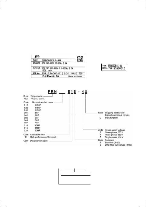
(3)The inverter is the model you ordered. You can check the model name and specifications on the main nameplate. (Main and sub nameplates are attached to the inverter and are located as shown on the following page.)
(a) Main Nameplate |
(b) Sub Nameplate |
Figure 1.1 Nameplates
TYPE: Type of inverter
002
SOURCE: Number of input phases (three-phase: 3PH, single-phase: 1PH), input voltage, input frequency, input current
OUTPUT: Number of output phases, rated output capacity, rated output voltage, output frequency range, rated output current, overload capacity
SER. No.: Product number
7 5 A 1 2 3 A 0 0 0 1 Z
Serial number of production lot
Production month
1 to 9: January to September
X, Y, or Z: October, November, or December
Production year: Last digit of year
If you suspect the product is not working properly or if you have any questions about your product, contact your Fuji Electric representative.
1-1

1.2 External View and Terminal Blocks
(1) Outside and inside views
Figure 1.2 Outside and Inside Views of Inverters (FRN020E1S-2U)
(2) Warning plates and label
Figure 1.3 Warning Plate and Sub Nameplate
(3) Terminal block location
|
|
(a) FRN001E1S-2U |
(b) FRN020E1S-2U |
|
Figure 1.4 Terminal Blocks |
|
|
1-2

1.3 Transportation
•When carrying an inverter, always support its bottom at the right and left sides with both hands. Do not hold covers or individual parts only.
•Avoid applying excessively strong force to the terminal block covers as they are made of plastic and are easily broken.
1.4 Storage Environment
1.4.1Temporary storage
Store the inverter in an environment that satisfies the requirements listed in Table 1.1.
Table 1.1 Environmental Requirements for Storage and Transportation
Item |
|
Requirements |
Storage temperature *1 |
-25(-13qF) to |
A location where the inverter is not subject to abrupt changes |
|
+70qC(158qF) |
in temperature that would result in the formation of |
Relative humidity |
5 to 95% *2 |
condensation or ice. |
Atmosphere |
The inverter must not be exposed to dust, direct sunlight, corrosive or |
|
|
flammable gases, oil mist, vapor, water drops or vibration. The atmosphere |
|
|
must contain only a low level of salt. (0.01 mg/cm2 or less per year) |
|
Atmospheric pressure |
86 to 106 kPa (in storage) |
|
|
70 to 106 kPa (during transportation) |
|
*1 Assuming a comparatively short storage period (e.g., during transportation or the like).
*2 Even if the humidity is within the specified requirements, avoid such places where the inverter will be subjected to sudden changes in temperature that will cause condensation to form.
Precautions for temporary storage
(1)Do not leave the inverter directly on the floor.
(2)If the environment does not satisfy the specified requirements, wrap the inverter in an airtight vinyl sheet or the like for storage.
(3)If the inverter is to be stored in an environment with a high level of humidity, put a drying agent (such as silica gel) in the airtight package described in item (2).
1.4.2Long-term storage
The long-term storage methods for the inverter vary largely according to the environment of the storage site. General storage methods are described below.
(1)The storage site must satisfy the requirements specified for temporary storage.
However, for storage exceeding three months, the ambient temperature should be within the range from -10°C(14qF) to +30°C(86qF). This is to prevent the electrolytic capacitors in the inverter from deteriorating.
(2)The inverter must be stored in a package that is airtight to protect it from moisture. Include a drying agent inside the package to maintain the relative humidity inside the package within 70%.
(3)If the inverter has been installed in the equipment or control panel at a construction site where it may be subjected to humidity, dust or dirt, then remove the inverter and store it in a suitable environment specified in Table 1.1.
Precautions for storage over 1 year
If the inverter will not be powered on for a long time, the property of the electrolytic capacitors may deteriorate. Power the inverters on once a year and keep them on for 30 to 60 minutes. Do not connect the inverter to a motor or run the motor.
1-3
Chapter 2 MOUNTING AND WIRING OF THE INVERTER
2.1 Operating Environment
Install the inverter in an environment that satisfies the requirements listed in Table 2.1.
|
Table 2.1 Environmental Requirements |
|
Item |
|
Specifications |
|
|
|
Site location |
Indoors |
|
|
|
|
Ambient |
-10qC(14qF) to +50qC(122qF) (Note 1) |
|
temperature |
|
|
|
|
|
Relative |
5 to 95% (No condensation) |
|
humidity |
|
|
|
|
|
Atmosphere |
The inverter must not be exposed to dust, |
|
|
direct sunlight, corrosive gases, flammable |
|
|
gas, oil mist, vapor or water drops. (Note 2) |
|
|
The atmosphere can contain only a low level |
|
|
of salt. |
|
|
(0.01 mg/cm2 or less per year) |
|
|
The inverter must not be subjected to sudden |
|
|
changes in temperature that will cause |
|
|
condensation to form. |
|
|
|
|
Altitude |
3300ft (1000 m) max. (Note 3) |
|
|
|
|
Atmospheric |
86 to 106 kPa |
|
pressure |
|
|
|
|
|
Vibration |
0.12inch(3 mm) |
2 to less than 9 Hz |
|
(Max. amplitude) |
|
|
|
|
|
9.8 m/s2 |
9 to less than 20 Hz |
|
2 m/s2 |
20 to less than 55 Hz |
|
1 m/s2 |
55 to less than 200 Hz |
Table 2.2 Output Current Derating Factor
in Relation to Altitude
Altitude |
Output current |
|
derating factor |
||
|
||
|
|
|
3300ft (1000m) or |
1.00 |
|
lower |
||
|
||
3300ft (1000) to |
0.97 |
|
4900ft (1500m) |
||
|
||
4900ft (1500) to |
0.95 |
|
6600ft (2000m) |
||
|
||
6600ft (2000) to |
0.91 |
|
8200ft (2500m) |
||
|
||
8200ft (2500) to |
0.88 |
|
9800ft (3000m) |
||
|
(Note 1) When inverters are mounted side-by-side without any gap between them (less than 7.5HP), the ambient temperature should be within the range from –10qC(14qF) to +40qC(104qF).
(Note 2) Do not install the inverter in an environment where it may be exposed to cotton waste or moist dust or dirt which will clog the heat sink in the inverter. If the inverter is to be used in such an environment, install it in the panel of your system or other dustproof containers.
(Note 3) If you use the inverter in an altitude above 3300ft(1000 m), you should apply an output current derating factor as listed in Table 2.2.
2.2 Installing the Inverter
(1) Mounting base
The temperature of the heat sink will rise up to approx. 90°C(194qF) during operation of the inverter, so the inverter should be mounted on a base made of material that can withstand temperatures of this level.
Install the inverter on a base constructed from metal or other non-flammable material.
A fire may result with other material.
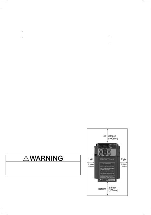
(2) Clearances
Ensure that the minimum clearances indicated in Figure 2.1 are maintained at all times. When installing the inverter in the panel of your system, take extra care with ventilation inside the panel as the temperature around the inverter will tend to increase. Do not install the inverter in a small panel with poor ventilation.
Figure 2.1 Mounting Direction and
Required Clearances
2-1

When mounting two or more inverters
Horizontal layout is recommended when two or more inverters are to be installed in the same unit or panel. If it is necessary to mount the inverters vertically, install a partition plate or the like between the inverters so that any heat radiating from an inverter will not affect the one/s above. As long as the ambient temperature is 40°C (104qF) or lower, inverters can be mounted side-by-side without any gap between them (only for inverters with a capacity of less than 7.5 HP).
When employing external cooling
At the shipment time, the inverter is set up for mount inside your equipment or panel so that cooling is done all internally.
To improve cooling efficiently, you can take the heat sink out of the equipment or the panel (as shown on the right) so that cooling is done both internally and externally (this is called "external cooling").
In external cooling, the heat sink, which dissipates about 70% of the total heat (total loss) generated into air, is situated outside the equipment or the panel. As a result, much less heat is radiated inside the equipment or the panel.
To take advantage of external cooling, you need to use the external cooling attachment option for inverters with a capacity of 7.5 HP or above.
In an environment with high humidity or a lot of fibrous dust, however, do not use external cooling in an environment with high humidity or a lot of fibrous dust, which tends to clog the heat sink.
For details, refer to the Mounting Adapter for External Cooling "PB-F1/E1" Installation Manual.
50°C
(122°F)"
Figure 2.2 External Cooling
Prevent lint, paper fibers, sawdust, dust, metallic chips, or other foreign materials from getting into the inverter or from accumulating on the heat sink.
This may result in a fire or accident.
2-2

(3) Mounting direction
Mount the inverter vertically to the mounting surface and fix it securely with four screws or bolts so that the logo "FRENIC-Multi" can be seen from the front.
Do not mount the inverter upside down or horizontally. Doing so will reduce the heat dissipation efficiency of the inverter and cause the overheat protection function to operate, so the inverter will not run.
(4) Solving abnormal vibration after installation
If any vibration in the surroundings reaches the inverter and causes abnormal vibration to the cooling fans or the keypad, fix them firmly using the fixing screws provided as accessories.
Fixing the cooling fans
Table 2.3 Fixing Screws
Power |
Nominal |
Inverter |
|
Screw |
Tightening |
|
applied |
|
|
||||
supply |
|
size |
torque |
|
||
motor |
type |
|
|
|||
voltage |
|
(accessory) |
(N·m) |
|
||
(HP) |
|
|
|
|||
|
|
|
|
|
|
|
|
7.5 |
FRN007E1 |
-2U |
|
|
|
Three- |
|
|
|
|
|
|
10 |
FRN010E1 |
-2U |
|
|
|
|
phase |
|
|
|
|
|
|
|
FRN015E1 |
-2U |
|
|
|
|
230 V |
15 |
|
|
|
||
|
|
|
|
|
|
|
|
20 |
FRN020E1 |
-2U |
M4x35 |
0.8 |
|
|
|
|
|
|
||
|
7.5 |
FRN007E1 |
-4U |
(4 pcs) |
|
|
|
|
|
||||
|
|
|
|
|||
Three- |
|
|
|
|
|
|
10 |
FRN010E1 |
-4U |
|
|
Figure 2.3 Fixing the Cooling Fans |
|
phase |
|
|
|
|
|
|
|
FRN015E1 |
-4U |
|
|
|
|
460 V |
15 |
|
|
|
||
|
|
|
|
|
|
|
|
20 |
FRN020E1 |
-4U |
|
|
|
|
|
|
|
|
|
|
Note 1) A box ( ) in the above table replaces S or E depending on the enclosure.
2-3

2.3 Wiring
Follow the procedure below. (In the following description, the inverter has already been installed.)
2.3.1Removing and mounting the terminal cover and the main circuit terminal block cover
(1) For inverters with a capacity of 5HP or below
To remove the terminal cover, put your finger in the dimple of the terminal cover (labeled "PULL"), and then pull it up toward you.
To remove the main circuit terminal block cover, hold its right and left ends with your fingers and slide it toward you.
Figure 2.4 Removing the Covers (For Inverters with a Capacity of 5HP or below)
2-4

(2) For inverters with a capacity of 7.5 and 10 HP
To remove the terminal cover, first loosen the terminal cover fixing screw on it, and put your finger in the dimple of the terminal cover (labeled "PULL"), and then pull it up toward you.
To remove the main circuit terminal block cover, put your thumbs on the handles of the main circuit terminal block cover, and push it up while supporting it with your fingers. (Refer to Figure 2.5.)
Figure 2.5 Removing the Covers (For Inverters with a Capacity of 7.5 and 10 HP)
When mounting the main circuit terminal block cover, fit it according to the guide on the inverter.
Figure 2.6 Mounting the main circuit terminal block cover (For Inverters with a Capacity of 7.5 and 10HP)
2-5

(3) For inverters with a capacity of 15 and 20 HP
To remove the terminal cover, first loosen the terminal cover fixing screw on it, and put your finger in the dimple of the terminal cover (labeled "PULL"), and then pull it up toward you.
To remove the main circuit terminal block cover, hold the handles on the both sides of the main circuit terminal block cover, and pull it up.
Figure 2.7 Removing the Covers (For Inverters with a Capacity of 15 and 20 HP)
When mounting the main circuit terminal block cover, fit it according to the guide on the inverter.
Insert the main circuit terminal block cover by fitting the part labeled "GUIDE" according to the guide on the inverter.
Push where "PUSH" are labeled to snap it into the inverter.
Figure 2.8 Mounting the Main Circuit Terminal Block Cover (For Inverters with a Capacity of 15 and 20 HP)
2-6

2.3.2Terminal arrangement diagram and screw specifications
The table below shows the main circuit screw sizes, tightening torque and terminal arrangements. Note that the terminal arrangements differ according to the inverter types. Two terminals designed for grounding shown as the symbol,  G in Figures A to E make no distinction between a power supply source (a primary circuit) and a motor (a secondary circuit).
(1) Arrangement of the main circuit terminals
Table 2.4 Main Circuit Terminal Properties
Power |
Nominal |
|
|
Terminal |
Tightening |
Ground- |
Tightening |
|
|
applied |
Inverter type |
Refer to: |
|||||||
supply |
screw |
torque |
ing screw |
torque |
|||||
motor |
|||||||||
voltage |
|
|
size |
(Ib-in (N·m)) |
size |
(Ib-in (N·m)) |
|
||
(HP) |
|
|
|
||||||
|
|
|
|
|
|
|
|
||
|
1/8 |
FRNF12E1 |
-2U |
|
|
|
|
|
|
|
1/4 |
FRNF25E1 |
-2U |
M3.5 |
10.6 |
M3.5 |
10.6 |
Figure A |
|
|
1/2 |
FRNF50E1 |
-2U |
(1.2) |
(1.2) |
||||
|
|
|
|
||||||
|
1 |
FRN001E1 |
-2U |
|
|
|
|
|
|
|
2 |
FRN002E1 |
-2U |
|
15.9 |
|
15.9 |
|
|
|
3 |
FRN003E1 |
-2U |
M4 |
M4 |
Figure B |
|||
|
(1.8) |
(1.8) |
|||||||
Three- |
5 |
FRN005E1 |
-2U |
|
|
|
|||
|
|
|
|
|
|||||
|
FRN007E1S-2U |
M5 |
33.6(3.8) |
|
33.6 |
Figure C |
|||
phase |
7.5 |
|
|
Input: M4 |
|
M5 |
|
||
FRN007E1E-2U |
15.9(1.8) |
(3.8) |
Figure F |
||||||
230 V |
|
Output: M5 |
|
||||||
|
|
|
|
|
|
|
|
||
|
10 |
FRN010E1S-2U |
M5 |
33.6(3.8) |
M5 |
33.6 |
Figure C |
||
|
|
|
Input: M4 |
|
|
||||
|
FRN010E1E-2U |
15.9(1.8) |
(3.8) |
Figure F |
|||||
|
|
Output: M5 |
|
||||||
|
|
|
|
|
|
|
|
||
|
15 |
FRN015E1S-2U |
|
51.3(5.8) |
M6 |
51.3 |
Figure C |
||
|
FRN015E1E-2U |
M6 |
71.7(8.1) |
(5.8) |
Figure F |
||||
|
|
|
|||||||
|
20 |
FRN020E1S-2U |
51.3(5.8) |
M6 |
51.3 |
Figure C |
|||
|
|
||||||||
|
FRN020E1E-2U |
|
71.7(8.1) |
(5.8) |
Figure F |
||||
|
|
|
|
||||||
|
1/2 |
FRNF50E1 |
-4U |
|
|
|
|
|
|
|
1 |
FRN001E1 |
-4U |
M4 |
15.9 |
M4 |
15.9 |
Figure B |
|
|
2 |
FRN002E1 |
-4U |
||||||
|
(1.8) |
(1.8) |
|||||||
|
3 |
FRN003E1 |
-4U |
|
|
|
|||
|
|
|
|
|
|
||||
|
5 |
FRN005E1 |
-4U |
|
|
|
|
|
|
|
7.5 |
FRN007E1S-4U |
M5 |
33.6(3.8) |
M5 |
33.6 |
Figure C |
||
|
|
|
Input: M4 |
|
|
||||
|
FRN007E1E-4U |
15.9(1.8) |
(3.8) |
Figure F |
|||||
Three- |
|
Output: M5 |
|
||||||
|
|
|
|
|
|
|
|||
phase |
|
FRN010E1S-4U |
M5 |
33.6(3.8) |
|
33.6 |
Figure C |
||
460 V |
10 |
|
|
|
|
M5 |
|
||
|
|
Input: M4 |
|
|
|||||
|
FRN010E1E-4U |
15.9(1.8) |
(3.8) |
Figure F |
|||||
|
|
Output: M5 |
|
||||||
|
|
|
|
|
|
|
|
||
|
15 |
FRN015E1S-4U |
M6 |
51.3(5.8) |
M6 |
51.3 |
Figure C |
||
|
|
|
Input: M4 |
|
|
||||
|
FRN015E1E-4U |
15.9(1.8) |
(5.8) |
Figure F |
|||||
|
|
Output: M6 |
|
||||||
|
|
|
|
|
|
|
|
||
|
20 |
FRN020E1S-4U |
M6 |
51.3(5.8) |
M6 |
51.3 |
Figure C |
||
|
|
|
Input: M4 |
|
|
||||
|
FRN020E1E-4U |
15.9(1.8) |
(5.8) |
Figure F |
|||||
|
|
Output: M6 |
|
||||||
|
|
|
|
|
|
|
|
||
|
1/8 |
FRNF12E1 |
-7U |
|
|
|
|
|
|
Single- |
1/4 |
FRNF25E1 |
-7U |
M3.5 |
10.6 |
M3.5 |
10.6 |
Figure D |
|
1/2 |
FRNF50E1 |
-7U |
(1.2) |
(1.2) |
|||||
phase |
|
|
|
||||||
1 |
FRN001E1 |
-7U |
|
|
|
|
|
||
230 V |
|
|
|
|
|
||||
|
2 |
FRN002E1 |
-7U |
M4 |
15.9 |
M4 |
15.9 |
Figure E |
|
|
3 |
FRN003E1 |
-7U |
(1.8) |
(1.8) |
||||
|
|
|
|
||||||
Note 1) A box ( ) in the above table replaces S or E depending on the enclosure.
2-7

Figure F |
(Note 1) |
|
Filter output (Note 2)
(Note 1) Terminal screw type is listed in the table below.
Inverter type |
Screw type |
|
FRN007E1E-2U |
Cross |
|
FRN010E1E-2U |
||
|
||
FRN015E1E-2U |
Hxagon |
|
FRN020E1E-2U |
||
|
||
FRN007E1E-4U |
Flat |
|
FRN010E1E-4U |
||
|
||
FRN015E1E-4U |
Cross |
|
FRN020E1E-4U |
||
|
(Note 2) Cables of EMC filter output are already connected to inverter input by factory default.
2-8
Loading...