


PXF5

- 1 -
Model : PXF5/9
Micro Control X
Instruction Manual
INP-TN2PXF5/9a-E
Grobal Sales Section
Instrumentation & Sensors Planning Dept.
1, Fuji-machi, Hino-city, Tokyo 191-8502, Japan
http://www.fujielectric.com
Phone: +81-42-514-8930 Fax: +81-42-583-8275
http://www.fujielectric.com/products/instruments/
Thank you for purchasing the Fuji module type temperature controller.
Once you have conrmed that this is the product you ordered, please use it in accordance with the following
instructions.
For detailed information on operating this equipment, please refer to the separate user's manual.
In addition, please keep this instruction manual within easy reach of the actual person using this equipment.
Please Read First (Safety Warnings)
Please read this section thoroughly before using and observe the mentioned safety warnings fully.
Safety warnings are categorized as “Warning” or “Caution”. Failure to follow the instructions may
result in a safety hazard.
Warning
mishandling may lead to minor or serious personal injury, re, and/or property damage.
Caution
Mishandling may cause injury to the user or property damage.
If the equipment is used in a manner not specied by the manufacturer, the protection provided by the
equipment may be impaired.
1. Warning
1-1. Limitations in Use
This product is a temperature controller which was developed, designed and manufactured on the
premise that it would be used for general machinery.
In particular, if this product is to be used for applications that require the utmost safety as described
below, please take into consideration of the safety of the entire system and the machine by adopting
such means as a fail-safe design, a redundancy design as well as the conducting of periodical
inspections.
• Safety devices for the purpose of protecting the human body
• Direct control of transportation equipment
• Airplanes
• Space equipment
• Atomic equipment, etc.
Please do not use this product for applications which directly involve human lives.
CAUTION
The contents of this manual are subject to change without notice.
This manual is complied with possible care for the purpose of accuracy, however,
Fuji Electric shall not be held liable for any damages, including indirect damage, caused by
typographical errors,
absence of information or use of information in this manual.
1-2. Installation and Wiring
► This equipment is intended to be used under the following conditions.
Ambient temperature -10 °C to 50 °C
Ambient humidity 90% RH or below (with no condensation)
Overvoltage category II
by IEC 61010-1
Pollution degree 2
Recommended fuse
250VAC, 0.1A T(Time-Lag) for 100 to 240V AC Power supply,
400V DC/400V AC, 1A T(Time-Lag) for 24V DC/24V AC Power supply
Usage environment Indoor use
► If accessible Safety Extra Low Voltage (SELV) circuits are to be connected to Signal input terminal,
SSR Drive output terminal, Current output terminal or Communication (RS485) terminal, ensure
to provide a basic insulation between the SELV circuits and these terminals (For example, use
transformer which has a basic insulation or higher degree of insulation). The basic insulation
requires a clearance at least 1.5 mm and a creepage of at least 3.0 mm. If such insulation is not
provided, the UL61010 and EN61010 safety compliance may become invalid.
► For 24V DC/AC power supply model, if the equipment is connected to the Safety Extra Low
Voltage (SELV) circuit, a basic insulation must be provided between the SELV circuit and the
power input terminals. Otherwise, the power input terminals must be connect to Extra Low Voltage
(ELV) circuit so as to prevent the electric shock.
► For CT input, use Current Transfer which has specication as shown below in order to prevent the
electric shock and spread of re.
1) Over Voltage Category II
2) Pollution Degree 2
3) Required level of Insulating
BASIC INSULATION, SUPPLYMENTARY INSULATION,
or REINFORCED INSULATION
4) Maximum Voltage line to neutral 300Vac rms or 300Vdc
About safety standard
Please observe the following instructions to meet the requirements of safety standard.
Failure to observe these instructions violates safety standards. (This product is not a safety equipment.)
………………………………………………………………………………………………………………………………
● Install a recommended fuse, which is specied in the instruction manual, between the external main power
(mains circuit) and this equipment.
● If accessible Safety Extra Low Voltage (SELV) circuits are to be connected to Signal input terminal, SSR
Drive output terminal, Current output terminal or Communication (RS485) terminal, ensure to provide a
basic insulation between the SELV circuits and these terminals (For example, use transformer which has a
basic insulation or higher degree of insulation). The basic insulation requires a clearance at least 1.5 mm
and a creepage of at least 3.0 mm. If such insulation is not provided, the UL61010 and EN61010 safety
compliance may become invalid.
● Whole this equipment must be mounted in an enclosure in order to prevent the electric shock and spread
of re.
● Be sure to install an appropriate external protective circuit to prevent excessive temperature rise etc.
● When performing wiring work, be sure to turn the power off and to wear protection gloves or safety glasses,
to prevent an electric shock.
● Set proper parameter input signals which correspond to each input to be connected. Be careful not to
confuse voltage input with current input, or vice versa.
● Do not use this equipment for the measurement of circuits which falls under measurement categories II, III,
or IV.
● Do not use this equipment for measurement of signals to which a voltage over 30 VRMS or over 60 V DC is
applied.
● If there is a risk that anyone may come into contact with the terminal while the instrument is being
energized, attach the terminal cover (optional) to prevent an electric shock. Before removing a terminal
cover, turn off all the power.
………………………………………………………………………………………………………………………………
► Note that the insulation class for this equipment is as follows. Before installing, please conrm that
the insulation class for equipment meets usage requirements.
Internal circuit
Process value input
Remote SV input
CT input
Valve position feedback
(PFB) input
Control output 1
(SSR drive, current, voltage)
Valve position feedback
(PFB) input
Control output 1
(SSR drive, current, voltage)
Control output 2 (SSR drive, current,
voltage) or Transfer output
Control output 2 (SSR drive, current,
voltage) or Transfer output
Digital input 1 to 5
Communication (RS-485)
Power supply (100 to 240V AC)
Control output 1 (relay contact)
or
Motorized valve OPEN output
Control output 2 (relay contact)
or
Motorized valve CLOSE output
Alarm output 1
(relay contact)
Alarm output
1 to 3
(relay contact)
Alarm output 2
(relay contact)
Control output 1 (relay contact)
or
Motorized valve OPEN output
Control output 2 (relay contact)
or
Motorized valve CLOSE output
Alarm output 1
(relay contact)
Alarm output
1 to 3
(relay contact)
Alarm output 2
(relay contact)
Basic insulation (1500 V AC) Functional insulation (500 V AC) No insulation
(1) (2) (1) (2)
Internal circuit
Process value input
Remote SV input
CT input
Digital input 1 to 5
Communication (RS-485)
Power supply (24V DC/24V AC)
Alarm output 4 and 5 (relay contact) Alarm output 4 and 5 (relay contact)
(1):When the 9th code is "J" AL 1 and 2: independent common
(2):When the 9th code is other than "J" AL 1 to 3: shared common
● A power switch or a circuit breaker should be installed within the power supply facility.
● A power switch or a circuit breaker should be properly installed within easy reach of an operator.
● A power switch or a circuit breaker should be identied as the one for this product.
● Electrical wiring must be made by the qualied personnel only and in accordance with your local
and national standards.
● For power supply wiring, use wire equal to 600V vinyl insulated wire or above.
● To prevent damage and failure of the equipment, provide the rated power voltage.
● To prevent shock and equipment failure, do not turn the power ON until all wiring is complete.
● Before turning on power, conrm that clearance space has been secured to prevent shock or re.
● Do not touch the terminal while the machine is on. Doing so risks shock or equipment errors.
● Never disassemble, convert, modify or repair this equipment. Doing so risks abnormal operation,
shock or re.
● If any failure occurs, please contact the manufacturer and return the product.
● Output relay is the part has a limited life. When output relay contact comes to the end of its life, it
might remain on-state, or off-state. For safety, use a protective circuit outside.
● The factory default setting of this equipment is as follows. Change the setting as necessary so
as the equipment to meet your application. Please note that the improper settings may result in
overheat or unexpected damage.
For the details of operation, refer to the separate volume, "Operation Manual (INP-TN5A2400-E)".
Control output 1: heating control
Control output 2 (optional): cooling control
Alarm output 1 (optional): no alarm
Alarm output 2 (optional): no alarm
Alarm output 3 (optional): no alarm
Alarm output 4 (optional): no alarm
Alarm output 5 (optional): no alarm
● Symbols on the instrument
: Read this instruction manual thoroughly before using the product, and usethe product safely.
1-3. Maintenance
● When installing or removing the equipment, turn the power OFF. Otherwise, shock, operational
errors or failures may be caused.
● Periodic maintenance is recommended for continuous and safe use of this equipment.
● Some parts installed on this equipment have a limited life and/or may deteriorate with age.
● The warranty period for this unit (including accessories) is three years after the date of manufacture,
if the product is used properly.
Conrming Specications and Accessories
Before using the product, confirm that it
matches the type ordered.
(For model code, please refer to pages 22 - 23.)
Conrm that all of the following accessories are
included.
Temperature Controller 1 unit
Instruction Manual 1 copy
Panel mounting adapter 2 pc
Waterproof packing 1 pc
Related Information
Refer to the following reference materials
for details about the items described in this
manual.
Document Reference No.
Data sheet
EDS11-179
EDS11-180
Micro Controller (Model: PXF)
Operation Manual
INP-TN5A2400-E
Micro Controller (Model: PXF)
Communication Functions
Manual (MODBUS)
INP-TN5A2227-E
The latest manuals can also be downloaded at the
following URL:
http://www.fujielectric.com/products/instruments/
Option
Name Quantity Order No.
Terminal cover* 1 pc ZZPPXF1-B100
PC loader
communication cable
1 cable ZZP*TQ501923C3
Shunt resistor
(250Ω ± 0.1%)
1 pc ZZPPXR1-A190
*For PXF9, two terminal covers are necessary for one unit.

- 2 -
- 3 -
2. Caution
2-1. Cautions when Installing
Please avoid installing in the following locations.
● Locations in which the ambient temperature falls outside the range of –10 to 50°C when equipment
is in use. (If the power supply is 200V AC, the recommended maximum ambient temperature is
45°C.)
● Locations with rapid temperature changes, leading to dew condensation
● Locations with corrosive gases (especially sulde gas, ammonia, etc.) or ammable gases.
● Locations with vibration or shock directly. (Vibration and shock may cause output relay malfunction.)
● Locations in contact with water, oil, chemicals, steam or hot water.
(If the equipment gets wet, there is a risk of electric shock or fire, so have it inspected by Fuji
distributor.)
● Locations with high concentrations of atmospheric dust, salt or iron particles.
● Locations with large inductive interference, resulting in static electricity, magnetic elds or noise
● Locations in direct sunlight.
● Locations that build up heat from radiant heat sources, etc.
Recommended site conditions
● A place where the ambient humidity during operaion is between 45 to 85%RH.
About EMC standard
● This equipment is a class A , for industrial locations, equipment. Do not use this equipment in domestic
establishment, such as residential areas, or it may cause radio interference. If you use this equipment in
domestic locations, take adequate measures on the outside of the equipment to reduce radio interference.
● Under the requirement of EMC standard, the maximum length of external cable including a sensor to be
connected to this equipment is 30 m. Do not connect the sensor longer than 30 m.
2-2. Cautions when Attaching to the Panels
● Please attach the PXF5/PXF9 with the included fixtures (2 pieces) to the top and bottom, and
tighten with a screwdriver.
● The clamp torque is approximately 0.15 N/m (1.5 kg/cm)
It is designed such that overtightening will cause left/right cracking to the central area of the Fixtures
and hence reduce the torque.
Cracking to the central area will not cause any problems in terms of usability of the equipment.
(However, do exercise caution in not applying too much torque because the casing is made of
plastic.)
● The front of this equipment is waterproof in compliance with NEMA-4X standards (IP66- equivalent).
To effect waterproof, the included packing is shall be attached between the controller and the
panel according to the guidelines below. (Incorrect attachment may cause the equipment to lose its
waterproof capabilities.)
(1) As shown in Fig. 1, insert to the panel after attaching the packing to the equipment case.
(2) As shown in Fig. 2, tighten the xture screws so that no gaps can remain between the equipment
face, the packing and the panels. Once nished, conrm that there are no changes in shape
such as displaced or improperly-tted packing, etc. as shown in Fig. 3.
● If the panel does not have enough strength, gaps may develop between the packing and the panel
to lose waterproong capabilities.
Fig. 1 Fig. 2 Fig. 3
Packing
Packing
Case
Case
(Bad)
(Good)
Unit
Front
Panel
Screw
Screw
Panel
Packing
Mounting fixture
Mounting fixture
Attachment on vertical surface
(Horizontal attachment)
Caution
● In order to aid heat dissipation, do not block the sides of the equipment.
● Do not block the air vents on the top and bottom of the case.
2-3. Cautions for Wiring
● For thermocouple input, use the designated compensation lead; for resistance bulb input, use wires
with small lead wire resistance and without any resistance difference among the three wires.
● To avoid noise conductor effects, input signal wires should be separated from electric power lines or
load lines.
● Input signal wire and output signal wire should be separated each other. And both should be shield
wire.
● If there is a lot of noise from the power source, adding an insulation transducer and using a noise
lter is recommended.
(Example: ZMB22R5-11, noise lter, Manufacturer: TDK)
Always attach a noise lter to a panel that is grounded securely, and keep the wiring between the
noise lter output side and the measuring equipment power terminal wiring to a minimum length.
Please do not attach fuses and switches, etc. to the noise lter output wiring; otherwise the lter’s
effectiveness will be decreased.
● Twisting the power wires is effective when connecting the wires. (The shorter the pitch of the twist,
the more effective the connection is against noise.)
● Operation preparation time is required for the contact output when power is turned on. If using it as
a signal to an external interlock circuit, please couple it with a delayed relay.
● Concerning the output relay, connecting the maximum rated load will shorten
the product’s life; so please attach an auxiliary relay. If the output operation
frequency is high, selecting a SSR/SSC drive output type is recommended.
[Proportionate cycles] Relay output: 30 seconds or more, SSR/SSC drive
output: 1 second or more
● If you selected the version with the heater break alarm, use a common
power line for the heater and the controller.
● When inductive loads such as magnetic opening/closing equipment, etc.
as relay output equipment are connected, use of a surge absorber is
recommended in order to protect the contacts against opening/closing
surges and to ensure long-term use.
Recommended specication for the surge absorber
Voltage Nominal varistor voltage
100 V 240 V
200 V 470 V
Attachment position: between the relay control output contacts.
(Example)
12
11
10
9
8
7
36
35
34
33
32
31
6
5
4
3
2
1
25
26
27
28
29
30
2-4. Key Operation Cautions/Error Operations
● The alarm function does not work properly when an error takes place unless the settings are made
correctly. Always verify its setting before operation.
● If the input wiring breaks, the display will read "UUUU". When replacing the sensor, always turn the
power OFF.
2-5. Others
● Please do not wipe the equipment with organic solvents such as alcohol or benzene, etc. If wiping
is necessary, use a neutral cleaning agent.
● Do not use mobile phones near this equipment (within 50 cm). Otherwise a malfunction may result.
● Trouble may occur if the equipment is used near a radio, TV, or wireless device.
● This equipment should be treated as an industrial waste when it is disposed of.
For Proper Usage
Please confirm that the model delivered matches your order.
"15 Model Specifications" (page 22)
Terminal connections diagram
"4 Wiring" (page 4)
Changing set value
Basic Operation Methods
Parameter List
Input/Output/Control
"5 Display and Operations" (page 6)
"5 Display and Operations" (page 6)
"6 Parameter List" (page 8 to 13)
"7 Functions" (page 14)
Setting of input sensor and input range
Selecting control method
Controlling through auto-tuning
tomatic setting parameters
"8-1 Input Setting" (page 18)
"8-3 Control Setting" (page 18)
"7-7 Auto-tuning" (page 15)
"7-3 Fuzzy PID Control", "7-4 Self-tuning Control" (page 14)
Display during equipment error
"9 Error Indications" (page 18)
External dimensions
• Panel cut dimensions
• Mounting the panel
"3 Installation and Mounting" (page 3)
Confirmation of model code
2
Wiring Connection
3 Display and Operations
4 Parameter List
5 Functions of the Temperature Controller
Turn Power On
6 Advanced Usage
7 Error Indications
Operation
1 Installation and Mounting
Caution
Wait 30 minutes for the controller to stabilized thermally. Operations such as
measurements should be taken after the equipment has been on for 30 minutes
or more.

- 3 -
3. Installation and Mounting
3-1. External/Panel Cut Dimensions
1-12
13-24 25-36
25-36
1-12
13-24
Installing multiple controllers
50 or more
(48 × n - 3)
92
+0.8
0
+0.8
0
Close mounting in horizontal direction (n units)
45
+0.6
0
92
0
116 or more
116 or more
+0.8
Installing multiple controllers
92
+0.8
0
92
+0.8
0
100 or more
Terminal block is not attached to unused terminals
(from terminal 13 to 24) depending on model.
Terminal screw
Rear view
6.2
Terminal block is not attached to unused terminals
(from terminal 13 to 24) depending on model.
Rear view
6.2
Terminal screw
Panel
Terminal cover
(Option)
Terminal cover
(Option)
48
96
Water proof
packing
8.7 57
2
MTG. Fixture MTG. Fixture
91.4
110.4
If with terminal cover
72.2
If with terminal cover
72.2
8.7 57
2
93.7
110.4
96
96
Water proof
packing
Terminal cover
93.7
Terminal cover
Panel
91.4
Horizontally close mounting does not meet
NEMA4X/IP66 (front waterproof specification),
because packing cannot be used in this mounting.
PXF5 PXF9
t (panel thickness) 1 ≤ t ≤ 8
*
* When using the parameter loader with PXF being mounted
on a panel: t (panel thickness) 1 ≤ t ≤ 4
t (panel thickness) 1 ≤ t ≤ 8
*
* When using the parameter loader with PXF being mounted
on a panel: t (panel thickness) 1 ≤ t ≤ 4
Caution
Panel cut dimensions should also meet the above dimensions after the panel is coated.
Cautions when Close Fit Mounting:
● When the power supply is AC 200V, keep the maximum ambient temperature at 45°C.
● If any equipment or walls which have a depth of 70 mm exist around this instrument,
keep a clearance of at least: 30 mm on the both sides, 50 mm below, 30 mm above.
Cautions when wiring:
● Start by wiring from the left-hand terminals (terminals 1 to 12).
● Use a screw that is the right size on terminals and tighten them with a torque of about 0.8
N/m.
● Do not attach anything to unused terminals. (Do not use relay terminals.)
- 4 -
- 5 -
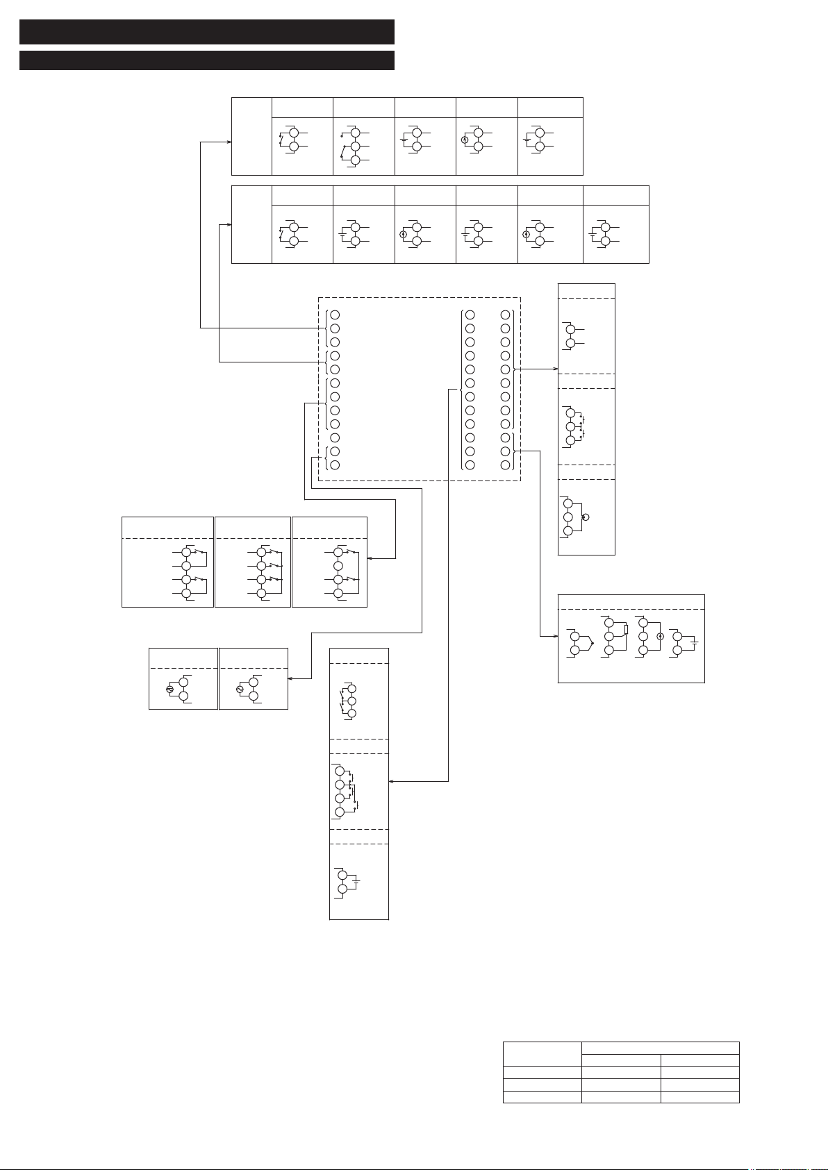
4. Wiring
4-1. Terminal Connection Diagram (Syandard type)
Alarm output
1 or 2 points3 points
2 points
(independent common)
9
8
7
6
9
8
7
6
9
8
7
6
AL1
AL2
AL2 COM
AL1 COM
AL1
AL3
COM
AL2
AL1
AL2
COM
Non-C
(Note 1)
Note 1: Power supplies for AL1 and AL2 must be of the same type,
either AC or DC.
Option
Digital input
DI2
DI1
DI-COM
RS-485
Remote SV input
CT input
CT1
RS485
+
–
Digital output
Digital input
Option
Standard type
-
+
-
+
–
+
–
+
–
+
–
+
–
+
–
+
-
+
Power supply
24VAC/24VDC
+
–
A
B
B
+
–
+
–
35
34
36
35
34
36
35
36
35
36
5
4
6
7
8
9
10
11
12
2
3
1
17
16
18
19
20
21
22
23
24
14
15
13
29
28
30
31
32
33
34
35
36
26
27
25
100-240VAC
50/60Hz 50/60Hz
12
11
12
11
26
25
28
29
27
32
33
31
DI4
DI5
DI3
DI-COM
AL5
AL4
COM
14
15
13
Relay output
(SPST)
2
1
5
4
5
4
5
4
5
4
5
4
5
4
Relay output
(SPDT)
Control
output 1
Control
output 2
SSR
Current
Voltage
2
1
2
1
2
1
2
3
1
COM
OUT1
COM
OUT1
COM
OUT1
COM
NC
NO
OUT1
OUT1
COM
OUT2
COM
OUT2
COM
OUT2
COM
OUT2
COM
OUT2
OUT2
Relay output
(SPST)
SSR
VoltageCurrent
Re-transmission
output (current)
Re-transmission
output (voltage)
RSV1
17
18
19
20
23
24
Process value input
Universal input
RTD Current
input
Voltage
input
Thermocouple
Control output 1
● Relay output (SPST)
250 V AC, 3 A (resistive load)
● Relay output (SPDT)
250 V AC, 5 A (resistive load)
● SSR output
12 V DC, 20 mA
● Current output
4 to 20 mA/0 to 20 mA (up to 500 Ω)
● Voltage output
0 to 5 V/1 to 5 V/0 to 10 V/2 to 10 V (MIN. 10 kΩ)
Control output 2
● Relay output
250 V AC, 3 A (resistive load)
● SSR output
12 V DC, 20 mA
● Current output
4 to 20 mA/0 to 20 mA (up to 500 Ω)
● Voltage output
0 to 5 V/1 to 5 V/0 to 10 V/2 to 10 V (MIN. 10 kΩ)
Alarm output 1 to 5
● Relay output
250 V DC, 1 A (resistive load)
Note) If you use PXF as a substitute for PXR or PXG which was used with
SSR output, be careful about the contlol voltage of SSR, for it is different
among PXR, PXG, and PXF.
Model
Output voltage range [V]
min max
PXF 10.7 13.2
PXR 17.0 25.0
PXG 18.0 24.0
Note) It is not necessary to make a mistake in the wiring for themeasurements
input terminal. There is a possibility that theinput circuit breaks when it
makes a mistake in wiring.
- 5 -
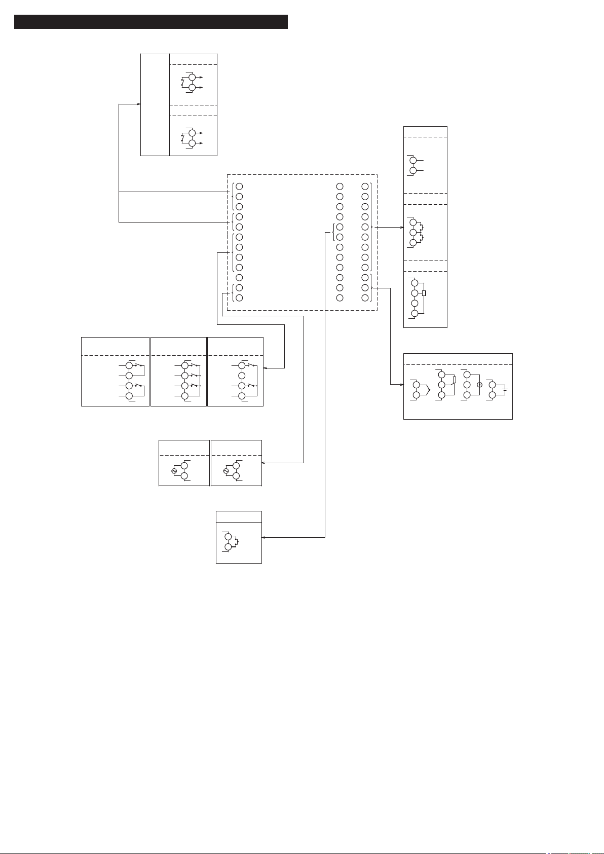
4-2. Terminal Connection Diagram (Motorized valve control type)
Alarm output
1 or 2 points3 points
2 points
(independent common)
9
8
7
6
9
8
7
6
9
8
7
6
AL1
AL2
AL2 COM
AL1 COM
AL1
AL3
COM
AL2
AL1
AL2
COM
Non-C
(Note 1)
Note 1: Power supplies for AL1 and AL2 must be of the same type,
either AC or DC.
I–
I+
Option
Digital input
Valve
control
output 1
Close
COM
Open
Valve Control
Valve Control
Motorized valve control type
COM
2
1
5
4
Power supply
24VAC/24VDC
100-240VAC
50/60Hz 50/60Hz
12
11
12
11
Digital input
DI2
DI1
DI-COM
RS-485
PFB input
PFB
RS485
Option
–
+
+
–
A
B
B
+
–
+
–
35
34
36
35
34
36
35
36
35
36
5
4
6
7
8
9
10
11
12
2
3
1
17
16
18
19
20
21
22
23
24
14
15
13
29
28
30
31
32
33
34
35
36
26
27
25
26
25
28
29
27
30
31
32
33
DI3
DI-COM
17
18
RTD Current
input
Voltage
input
Thermocouple
Universal input
Process value input
Valve control output 1
● Relay output
250 V AC, 3 A (resistive load)
Alarm output 1 to 3
● Relay output
250 V DC, 1 A (resistive load)

- 6 -
- 7 -
5. Display and Operations
5-1. Part names and functions
Operation parts
USER key
SEL key
USER + key
USER + key
key
key
USER Key
Press this key once in PV/SV display to switch between SV display and MV display.
Press and hold this key in PV/SV display to start the assigned function.
Press this key once in operation control mode, channel-selection mode, or setup mode to return to
PV/SV display.
SEL key
Press this key once in operation mode to move to operation control mode.
Press and hold this key in operation mode to move to channel selection mode.
Press this key once in channel selection mode to move to setup mode.
Press and hold this key in setup mode to move to channel selection mode.
Press this key once in parameter selection submode of setup mode to enter parameter editing
submode.
Press this key once in parameter editing submode to save the change and return to parameter
selection submode.
key
Use this key to select the digit when changing values.
keys
Use this key to change SV value when in PV/SV screen.
Press this key in operation control mode, channel selection mode, or setup mode, to change
parameters to be displayed.
Use this key to edit parameter when in parameter setting submode.
USER+
key
Press and hold this key in PV/SV display to start the assigned function.
(The factory set function for this key is switching between RUN and standby.)
USER+ key
Press and hold this key in PV/SV display to start the assigned function.
(The factory set function for this key is switching between start/stop of auto-tuning.)
Display
(3)
(1)
(16)
(2)
(9) (18)
(6)
(7)
(8)
(12)
(11)
(5)
(4)
PXF5
(2)
(1)
(17)
(3) (18)(9)(12)
(11)
(15)
(14)
(13)
(10)
(4) (5) (6) (7) (8)
PXF9
(17)
(13)
(14)
(15)
(10)
(16)
(1) Process value (PV)
Indicates process value. Shows parameter name when in parameter setting.
(2) Set point (SV)
Shows set point. Shows parameter set value when in parameter setting.
(3) Screen No.
Shows screen No. when in parameter setting.
(4) OUT 1 indicator
Lights during control output 1 is ON.
(5) OUT 2 indicator
Lights during control output 2 is ON.
(6) EV 1, EV 2, EV 3 indicators
Lights during digital output 1 to 3 are ON.
(7) STBY indicator
Lights during standby.
(8) MANU indicator
Lights during manual mode.
(9) Lock indicator
Lights during key lock.
(10) No. indicator
Lights during indicating screen No.
(11) RUN/HOLD/END indicators
Lights during ramp/soak operation.
(12) AT indicator
Lights during auto tuning.
(13) MV indicator
Lights during MV is indicated on SV display.
(14) TM indicator
Lights during the time is indicated on SV display.
(15) RMN indicator
Lights during remaining time is indicated on SV display.
(16) °C/°F indicator
Shows the temperature unit under use.
(17) A/%/kW/h indicator
Shows the unit under use for the values indicated on SV display.
(18) Bar graph display
Displays a bar graph of control output (MV) during operation.

- 7 -
5-2. Basic Operations
The below gure illustrates the mode transition and the key operations.
Operation mode
Operation control mode
Channel selection mode
Setup mode
In this mode the normal operation is performed. The process value (PV) and the set value (SV) are displayed. The device starts in this mode when you turn on the
power. You can change the set value (SV) in this mode. You can check the output value (MV) and the amount of electric ower by switchin the screen.
In this mode you can put the device to standby or change the alarm set value.
In this mode you can select the parameter channel to be displayed.
In this mode you can setup each parameter. This mode includes the parameter selection submode and the parameter editing submode, which can be switched by
SEL key. In the parameter selection submode, you can switch between parameters by using ΛV keys. In the parameter editing submode, you can change parameter
values by using ΛV keys.
Power ON
Operation
mode
(Operation
screen)
PV/SV display
PV/power
PV/MV display
AUTO/MANUAL
Press
and hold
P
Press
and hold
in the selected channel
Parameter
ex) ch1 PID
Parameter
Operation
control mode
Setup mode
Channel
selection mode
Ch1 Ch2 Ch3 Ch4 Ch5 Ch6
PID PLT PRG MON ALM SET
Ch7 Ch8 Ch9 Ch11 Ch12 Ch13
SYS MATH COM DSP CFG PASS
i
d
Channel
5-3. Changing values on operation screen
● Changing SV (set values)
Change the display to PV/SV display (shown when you turn on the power and the SV lamp is
lit).
Change the SV with the
keys.
Press the
key to save the values.
(The value will be automatically saved after 3 seconds even if a key is not pressed.)
1
2
3
● Changing MV (control output values)
Switch to manual mode.
Change the display to PV/MV display (MAN/AT/SELF lamp is lit).
(Pressing the
key in manual mode toggles between PV/SV display and PV/MV display.)
Change the MV with the
keys.
(Changes are reected to the MV as it is changed.)
See “7-8 Manual Output” (page 15) for more about changing to manual mode.
1
2
3

- 8 -
- 9 -
6. Parameter List
The following explains each channel parameter.
● The list also shows the operational range of set values for parameters that are limited.
● When the PV input lower limit (Pvb), PV input upper limit (PvF), or decimal place position (Pvd) is
changed, recongure all the initial parameter setting values.
● When the parameter that has [RESET] on its Remarks column is changed, turn off the power once,
and then re-start the controller.
Operation control parameter
Parameter
Function Setting range Initial value Remarks
№ Display Name
1
Switchover between auto and manual
mode
Switchover between auto and manual modes oFF (auto) / on(manual) oFF This parameter is not displayed in default setting. If you
need to change this parameter, change the setting of
"Ch11 dSP" so that it appears.
2 Switchover between RUN and standby Switchover the operation mode between RUN and standby oFF(RUN) / on(standby) oFF
3
Local/remote switchover Switches the operation between local/remote SV. LoCL (local)/ REM (remote) LoCL
4
Ramp soak control command Changes ramp soak run states oFF (stop)rUn (run)hLd (hold) oFF Displays End (when ending) or GS (during guaranty
soak).
5 Auto-tuning run command Runs auto-tuning. oFF (stop/nish) on (normal type)
L-oN (low PV type)
oFF
6
Alarm output latch release command Cancels the alarm output latch state oFF / rST (latch resets) oFF
7
SV selection Chooses the SV No. used for control LoCL
Sv1
Sv2
Sv3
Sv4
Sv5
Sv6
Sv7
di (depending on DI)
LoCL "When changing the SV with the front key, do not
change the “Svn” parameter via communication.
Otherwise, the changed SV may not be stored
correctly."
8 PID selection Chooses the PID No. used for control LoCL
Pid 1 (PID group No. 1)
Pid 2 (PID group No. 2)
Pid 3 (PID group No. 3)
Pid 4 (PID group No. 4)
Pid 5 (PID group No. 5)
Pid 6 (PID group No. 6)
Pid 7 (PID group No. 7)
di (depending on DI)
LoCL
9
ALM1 set value
Sets the alarm value for ALM1. Absolute value alarm: 0 to 100% FS
Deviation alarm: -100 to 100% FS
2.50%FS
10
11
12
ALM2 set value
Sets the alarm value for ALM2. Absolute value alarm: 0 to 100% FS
Deviation alarm: -100 to 100% FS
2.50%FS
13
14
15
ALM3 set value
Sets the alarm value for ALM3. Absolute value alarm: 0 to 100% FS
Deviation alarm: -100 to 100% FS
2.50%FS
16
17
18
ALM4 set value
Sets the alarm value for ALM4. Absolute value alarm: 0 to 100% FS
Deviation alarm: -100 to 100% FS
2.50%FS
19
20
21
ALM5 set value
Sets the alarm value for ALM5. Absolute value alarm: 0 to 100% FS
Deviation alarm: -100 to 100% FS
2.50%FS
22
23
27 Electric power calculation command Switches among on/off/hold of electric power calculation. oFF (stop calculation)
rUn (run calculation)
hLd (suspend calculation)
oFF
28 Key lock Sets the key lock to prevent wrong operation oFF (no lock)
ALL (all lock)
PArA (All but SV locked)
oFF
Ch1 PID (control parameters)
Parameter
Function Setting range Initial value Remarks
№ Display Name
50
Proportional band (%) Sets the proportional band of the PID parameter. 0.1 to 999.9% 5.0%
51
Integration time "Sets the integration time of the PID parameter.
Setting ""0"" will turn off integration."
0 to 3200 sec 240 sec
52
Differential time "Sets the differential band of the PID parameter.
Setting ""0"" will turn off differentiation."
0.0 to 999.9 sec 60.0 sec
53 ON/OFF control hysteresis Sets the hysteresis width for the ON/OFF control. 0 to 50%FS 0.25%FS
54
Cooling proportional band coefcient "Sets the proportional band coefcient for cooling.
Setting ""0.0"" will turn the cooling into an ON/OFF control."
0.0 to 100.0 1.0
55 Dead band (%) Shifts the cooling proportional band from the set value -50.0 to 50.0% 0.0%
56
Output convergence value (%) Offset value which is added to the MV output value -100.0 to 100.0% 0/50 (single/dual)
57
Anti-reset windup Sets the range of integration control 0 to 100%FS 100%FS
58
Normal/reverse operations "Selects single control or dual control. Sets the control action
(normal or reverse)."
rv-- (heat (reverse)/cool (none))
no-- (heat (normal)/cool (none))
rvno (heat (reverse)/cool (normal))
norv (heat (normal)/cool (reverse))
rvrv (heat (reverse)/cool (reverse))
nono (heat (normal)/cool (normal))
rv--/rvno
(single/dual)
[RESET]
59 SV limit (lower) Sets the lower limit of SV 0 to 100%FS 0.00%FS Note 1)
60
SV limit (upper) Sets the upper limit of SV 0 to 100%FS 100.00%FS Note 1)
61
OUT1 proportion cycle "Sets the proportion cycle of the control output (OUT1)
(contacts, SSR drive)"
1 to 150 sec 30 (relay)
2 (SSR)
1 (current)
62 OUT2 proportion cycle "Sets the proportion cycle of the control output (OUT2)
(contacts, SSR drive)"
1 to 150 sec 30 (relay)
2 (SSR)
1 (current)
63
OUT1 lower limit Sets the lower limit of the control output(OUT1) -5.0 to 105.0% -5.0%
64
OUT1 upper limit Sets the upper limit of the control output(OUT1) -5.0 to 105.0% 105.0%
65
OUT2 lower limit Sets the lower limit of the control output(OUT2) -5.0 to 105.0% -5.0%
66
OUT2 upper limit Sets the upper limit of the control output(OUT2) -5.0 to 105.0% 105.0%
67
Type of output limiter Sets the type of output limiter 0 to 15 0
73
Alpha Sets 2-degrees-of-freedom coefcient α -199.9to 300.0% 40.0%
74
Beta Sets 2-degrees-of-freedom coefcient β 0.0 to 999.9% 100.0%
Note 1: “SvL” and “Svh” must be set so that SvL < Svh. When you change the values for “SvL” and “Svh”, check SV 1 (“Sv1 Ch2”) through SV 7 (“Sv7 Ch2”).
 Loading...