


 Loading...
|
|
|
|
°C |
C1 |
C2 |
AL1 |
AL2 |
AL3 |
PV |
|
|
|
|
SV |
|
|
|
|
|
SEL |
|
|
|
PXR |
|
|
|
|
Micro-controller X
Model: PXR4/5/9
Operation Manual
ECNO:406e

Table of Contents
1. Part Names and Functions ........................................................ |
6 |
|
2. Operations ................................................................................. |
7 |
|
2-1 |
Parameter list ..................................................................................... |
7 |
2-2 |
Basic operations ............................................................................... |
12 |
2-3 |
Parameter functions and method of settings .................................... |
14 |
Manual mode setting ................................................................................................. |
15 |
|
Standby setting .......................................................................................................... |
16 |
|
Local/remote operation setting .................................................................................. |
17 |
|
Ramp-soak control ..................................................................................................... |
18 |
|
Canceling the alarm latch .......................................................................................... |
19 |
|
Auto-tuning function ................................................................................................... |
20 |
|
Displaying ON-delay alarm or the remaining time of timers ...................................... |
21 |
|
Setting alarm 1, 2 and 3 ............................................................................................ |
22 |
|
Upper limit of alarm 1, 2 and 3 .................................................................................. |
22 |
|
Lower limit of alarm 1, 2 and 3 ................................................................................... |
22 |
|
Key lock ..................................................................................................................... |
23 |
|
Proportional band ...................................................................................................... |
24 |
|
Integral time ............................................................................................................... |
25 |
|
Derivative time ........................................................................................................... |
26 |
|
Hysteresis range for ON/OFF control ........................................................................ |
27 |
|
Cooling-side proportional band coefficient ................................................................ |
28 |
|
Cooling-side proportional band shift (Dead band/Overlap band) .............................. |
29 |
|
Output offset value ..................................................................................................... |
30 |
|
Anti-reset windup ....................................................................................................... |
30 |
|
Control algorithm ....................................................................................................... |
31 |
|
PV (Measured value) stable range ............................................................................ |
35 |
|
HYS (Hysteresis) mode at ON/OFF control ............................................................... |
36 |
|
Cycle time of control output 1 .................................................................................... |
37 |
|
Cycle time of control output 2 (Cooling-side) ............................................................. |
38 |
|
Input signal code ........................................................................................................ |
39 |
|
Setting the measuring range (Input range) ................................................................ |
40 |
|
Selection °C / °F ........................................................................................................ |
40 |
|
Decimal point position ................................................................................................ |
42 |
|
PV (Measured value) offset ....................................................................................... |
43 |
|
SV (Setting value) offset ............................................................................................ |
44 |
|
Time constant of input filter ........................................................................................ |
45 |
|
Alarm types ................................................................................................................ |
46 |
|
Selecting ramp-soak patterns .................................................................................... |
49 |
|
Ramp-soak status display .......................................................................................... |
50 |
|
1st to 8th target SV .................................................................................................... |
50 |
|
1st to 8th ramp segment time .................................................................................... |
50 |
|
1st to 8th soak segment time ..................................................................................... |
50 |
|
Ramp-soak modes ..................................................................................................... |
50 |
|
2

Specifying control action and output direction at input burn-out |
................................ 53 |
SV (Setting value) lower limiter .................................................................................. |
54 |
SV (Setting value) upper limiter ................................................................................. |
54 |
The time of ON-delay alarm or timer function ............................................................ |
55 |
Displaying current detector input ............................................................................... |
57 |
HB (Set value of heater break alarm) ........................................................................ |
57 |
Hysteresis alarm 1, 2 and 3 ....................................................................................... |
59 |
Options of alarm 1, 2 and 3 ....................................................................................... |
60 |
Upper and lower limits for control output 1 ................................................................ |
62 |
Upper and lower limits for control output 2 ................................................................ |
62 |
Output limit types ....................................................................................................... |
63 |
Output value display .................................................................................................. |
64 |
RCJ (Cold junction compensation) ............................................................................ |
65 |
Adjusting the PV (Measured value) display (0%) ....................................................... |
66 |
Adjusting the PV (Measured value) display (100%) ................................................... |
66 |
DI1/2 (Digital input 1/2) operation .............................................................................. |
67 |
Station No. for communication ................................................................................... |
70 |
Parity for communication ........................................................................................... |
71 |
Communication protocol setting ................................................................................ |
72 |
Re-transmission output type setting .......................................................................... |
73 |
Re-transmission base and span scale ....................................................................... |
74 |
Remote SV input (0%) adjustment ............................................................................ |
75 |
Remote SV input (100%) adjustment ........................................................................ |
75 |
Remote SV input filter constant ................................................................................. |
76 |
Remote SV input value display .................................................................................. |
77 |
Parameter display mask ............................................................................................ |
78 |
3. Troubleshooting ....................................................................... |
79 |
Index ............................................................................................ |
81 |
3

PXR4
|
|
|
|
|
4 |
5 |
6 |
7 |
8 |
9 |
10 |
11 |
12 |
13 |
||||||||||||
|
|
|
|
|
PXR |
|
|
|
|
|
|
|
|
1 |
- |
|
|
|
|
|
|
|
|
|
|
|
|
|
|
|
|
|
|
|
|
|
|
|
|
|
|
|
|
|
|
|
|
|
|
|
|
|
|
|
|
|
|
|
|
|
|
|
|
|
|
|
|
|
|
|
|
|
|
|
|
|
|
|
|
|
Digit |
|
|
Specification |
|
Note |
|
|
|
|
|
|
|
|
|
|
|
|
|
|
|
|
|
|
|
|
|
4 |
<Front dimensions> |
|
|
|
|
|
|
|
|
|
|
|
|
|
|
|
|
|
|
|
|
|
|
|
||
|
|
4 |
|
|
|
|
|
|
|
|
|
|
|
|
|
|
|
|
|
|
|
|||||
|
48 X 48mm |
|
|
|
|
|
|
|
|
|
|
|
|
|
|
|
|
|
|
|
|
|
|
|
||
|
|
|
|
|
|
|
|
|
|
|
|
|
|
|
|
|
|
|
|
|
|
|
|
|
|
|
5 |
<Input signal> |
°C |
|
|
|
|
|
|
|
|
|
|
|
|
|
|
|
|
|
|
|
|
|
|
|
|
|
|
|
|
T |
|
|
|
|
|
|
|
|
|
|
|
|
|
|
|
|
|
|||||
|
Thermocouple |
|
|
|
|
|
|
|
|
|
|
|
|
|
|
|
|
|
|
|
|
|
||||
|
Thermocouple |
°F |
°C |
|
|
|
R |
|
|
|
|
|
|
|
|
|
|
|
|
|
|
|
|
|
||
|
Resistance bulb Pt100 3-wire type |
|
|
|
N |
|
|
|
|
|
|
|
|
|
|
|
|
|
|
|
|
|
||||
|
Resistance bulb Pt100 3-wire type |
°F |
|
|
|
S |
|
|
|
|
|
|
|
|
|
|
|
|
|
|
|
|
|
|||
|
1 to 5V DC |
|
|
|
|
|
|
A |
|
|
|
|
|
|
|
|
|
|
|
|
|
|
|
|
|
|
|
4 to 20mA DC |
|
|
|
|
|
B |
|
|
|
|
|
|
|
|
|
|
|
|
|
|
|
|
|
||
6 |
<Control output 1> |
|
|
|
|
|
|
|
|
|
|
|
|
|
|
|
|
|
|
|
|
|
|
|
||
|
|
|
|
|
|
A |
|
|
|
|
|
|
|
|
|
|
|
|
|
|
|
|||||
|
Relay contact output |
|
|
|
|
|
|
|
|
|
|
|
|
|
|
|
|
|
|
|
|
|
||||
|
Voltage pulse output (24V DC) |
|
|
|
|
|
|
C |
|
|
|
|
|
|
|
|
|
|
|
|
|
|
|
|||
|
4 to 20mA DC output |
|
Note 1 |
|
|
|
|
E |
|
|
|
|
|
|
|
|
|
|
|
|
|
|
|
|||
7 |
<Control output 2> |
|
|
|
|
|
|
|
|
|
|
|
|
|
|
|
|
|
|
|
|
|
|
|
||
|
|
|
|
|
|
|
|
Y |
|
|
|
|
|
|
|
|
|
|
|
|
|
|||||
|
None |
|
|
|
|
|
|
|
|
|
|
|
|
|
|
|
|
|
|
|
|
|
|
|
||
|
Relay contact output |
|
Note 2 |
|
|
|
|
|
|
A |
|
|
|
|
|
|
|
|
|
|
|
|
|
|||
|
Voltage pulse output (24V DC) |
|
Note 2 |
|
|
|
|
|
|
C |
|
|
|
|
|
|
|
|
|
|
|
|
|
|||
|
4 to 20mA DC output |
|
Note 2 |
|
|
|
|
|
|
E |
|
|
|
|
|
|
|
|
|
|
|
|
|
|||
|
Re-transmission output (4 to 20mA DC) |
Note 2 |
|
|
|
|
|
|
R |
|
|
|
|
|
|
|
|
|
|
|
|
|
||||
|
|
|
|
|
|
|
|
|
|
|
|
|
|
|
|
|
|
|
|
|||||||
8 |
<Revision code> |
|
|
|
|
|
|
|
|
|
|
1 |
|
|
|
|
|
|
|
|
|
|
|
|||
9 |
<Optional specifications 1> |
|
|
|
|
|
|
|
|
|
|
|
|
|
|
|
|
|
|
|
|
|
|
|
||
|
|
|
|
|
|
|
|
|
|
|
|
|
|
|
|
|
|
|
|
|
|
|
||||
|
None |
|
|
|
|
|
|
|
|
|
|
|
|
|
|
0 |
|
|
|
|
|
|
|
|
||
|
Alarm (1 pc.) |
|
|
|
|
|
|
|
|
|
|
|
|
|
|
1 |
|
|
|
|
|
|
|
|
||
|
Alarm for heater break |
|
Note 3 |
|
|
|
|
|
|
|
|
|
|
2 |
|
|
|
|
|
|
|
|
||||
|
Alarm (1 pc.) + Alarm for heater break |
Note 3 |
|
|
|
|
|
|
|
|
|
|
3 |
|
|
|
|
|
|
|
|
|||||
|
Ramp-soak |
|
|
|
|
|
|
|
|
|
|
|
|
|
|
4 |
|
|
|
|
|
|
|
|
||
|
Alarm (1 pc.) + Ramp-soak |
|
Note 3 |
|
|
|
|
|
|
|
|
|
|
5 |
|
|
|
|
|
|
|
|
||||
|
Alarm for heater break + Ramp-soak |
|
|
|
|
|
|
|
|
|
|
|
6 |
|
|
|
|
|
|
|
|
|||||
|
Alarm (1 pc.) + Alarm for heater break + Ramp-soak |
Note 3 |
|
|
|
|
|
|
|
|
|
|
7 |
|
|
|
|
|
|
|
|
|||||
|
Alarm (2 pcs.) |
|
|
|
|
|
|
|
|
|
|
|
|
|
|
F |
|
|
|
|
|
|
|
|
||
|
Alarm (2 pcs.) + Ramp-soak |
|
Note 3 |
|
|
|
|
|
|
|
|
|
|
|
G |
|
|
|
|
|
|
|
|
|||
|
Alarm (2 pcs.) + Alarm for heater break + Ramp-soak |
|
|
|
|
|
|
|
|
|
|
|
H |
|
|
|
|
|
|
|
|
|||||
|
Alarm (3 pcs.) |
|
|
|
|
|
|
|
|
|
|
|
|
|
|
M |
|
|
|
|
|
|
|
|
||
|
Remote SV |
|
|
|
Note 3 |
|
|
|
|
|
|
|
|
|
|
|
D |
|
|
|
|
|
|
|
|
|
|
Remote SV + Alarm (2 pcs.) |
|
Note 3 |
|
|
|
|
|
|
|
|
|
|
|
P |
|
|
|
|
|
|
|
|
|||
10 |
<Instruction manual> <Power supply voltage> |
|
|
|
|
|
|
|
|
|
|
|
|
|
|
N |
|
|
|
|
|
|
||||
|
None |
|
100 to 240V AC |
|
|
|
|
|
|
|
|
|
|
|
|
|
|
|
|
|
|
|
|
|||
|
English |
|
100 to 240V AC |
|
|
|
|
|
|
|
|
|
|
|
|
|
|
V |
|
|
|
|
|
|
||
|
None |
|
24V DC |
|
|
|
|
|
|
|
|
|
|
|
|
|
|
|
C |
|
|
|
|
|
|
|
|
English |
|
24V DC |
|
|
|
|
|
|
|
|
|
|
|
|
|
|
|
B |
|
|
|
|
|
|
|
|
|
|
|
|
|
|
|
|
|
|
|
|
|
|
|
|
|
|
|
|
|
|
|
|
||
11 |
<Optional specifications 2> |
|
|
|
|
|
|
|
|
|
|
|
|
|
|
|
|
|
|
|
|
|
|
|
||
12 |
None |
|
|
|
|
|
|
|
|
|
|
|
|
|
|
|
|
|
|
|
0 |
0 |
0 |
|||
13 |
RS485 (Modbus) communication |
|
|
|
|
|
|
|
|
|
|
|
|
|
|
|
|
|
M |
0 |
0 |
|||||
|
RS485 (ASCII) communication |
|
|
|
|
|
|
|
|
|
|
|
|
|
|
|
|
|
N |
0 |
0 |
|||||
|
Digital input |
1 point |
|
|
|
|
|
|
|
|
|
|
|
|
|
|
|
|
|
S |
0 |
0 |
||||
|
Digital input |
2 points |
|
Note 4 |
|
|
|
|
|
|
|
|
|
|
|
|
|
|
|
T |
0 |
0 |
||||
|
RS485 (Modbus) communication + Digital input 1 point |
|
|
|
|
|
|
|
|
|
|
|
|
|
|
|
|
V |
0 |
0 |
||||||
|
RS485 (ASCII) communication + Digital input 1 point |
|
|
|
|
|
|
|
|
|
|
|
|
|
|
|
|
W |
0 |
0 |
||||||
|
|
|
|
|
|
|
|
|
|
|
|
|
|
|
|
|
|
|
|
|
|
|
|
|
|
|
Note 1: Cannot be combined with heater break alarm. ( 2, 3, 6, 7, H cannot be specified on 9th digit.)
Note 2: Cannot be combined with alarm (1 pc.) + heater break alarm, alarm (2 pcs.), or alarm (3pcs.). ( 3, 7, F, G, H, M, P cannot be specified on 9th digit.)
Note 3: Cannot be combined with RS485 + 1-point digital input. (V and W cannot be specified on 11th digit.)
Note 4: In the case of control output 2, either of heater break alarm or remote SV input can be selected. (A, C, E and R on the 7th digit, and 2,3,6,7,H, D and P on the 9th digit cannot be specified.)
Input signal, measurement range, and set value at the time of deliver are as follows.
When thermocouple is specified: Thermocouple K, Measurement range; 0 to 400°C, Set value; 0°C When resistance bulb is specified: Pt, Measurement range; 0 to 150°C, Set value; 0°C
When voltage/current is specified: Scaling; 0 to 100%, Set value; 0%
For the cases other than the above, specify input signal and measurement range.
Input signal of the thermocouple and the resistance bulb can be switched by key operation on the front panel.
The actuating method of the control output has been set to reverse for control output 1, and to direct for control output 2 at the time of delivery. Note that reverse and direct actuation can be switched by key operation on the front panel.
4

PXR5/9
|
|
|
|
|
4 |
5 |
6 |
7 |
8 |
9 |
10 |
11 |
12 |
13 |
||||||||||||
|
|
|
|
|
PXR |
|
|
|
|
|
|
|
|
1 |
- |
|
|
|
|
|
|
|
|
|
|
|
|
|
|
|
|
|
|
|
|
|
|
|
|
|
|
|
|
|
|
|
|
|
|
|
|
|
|
|
|
|
|
|
|
|
|
|
|
|
|
|
|
|
|
|
|
|
|
|
|
|
|
|
|
|
Digit |
|
|
Specification |
|
Note |
|
|
|
|
|
|
|
|
|
|
|
|
|
|
|
|
|
|
|
|
|
4 |
<Front dimensions> |
|
|
|
|
|
|
|
|
|
|
|
|
|
|
|
|
|
|
|
|
|
|
|
||
|
|
5 |
|
|
|
|
|
|
|
|
|
|
|
|
|
|
|
|
|
|
|
|||||
|
48 X 96mm |
|
|
|
|
|
|
|
|
|
|
|
|
|
|
|
|
|
|
|
|
|
|
|
||
|
96 X 96mm |
|
|
|
|
9 |
|
|
|
|
|
|
|
|
|
|
|
|
|
|
|
|
|
|
|
|
5 |
<Input signal> |
°C |
|
|
|
|
|
|
|
|
|
|
|
|
|
|
|
|
|
|
|
|
|
|
|
|
|
|
|
|
T |
|
|
|
|
|
|
|
|
|
|
|
|
|
|
|
|
|
|||||
|
Thermocouple |
|
|
|
|
|
|
|
|
|
|
|
|
|
|
|
|
|
|
|
|
|
||||
|
Thermocouple |
°F |
°C |
|
|
|
R |
|
|
|
|
|
|
|
|
|
|
|
|
|
|
|
|
|
||
|
Resistance bulb Pt100 3-wire type |
|
|
|
N |
|
|
|
|
|
|
|
|
|
|
|
|
|
|
|
|
|
||||
|
Resistance bulb Pt100 3-wire type |
°F |
|
|
|
S |
|
|
|
|
|
|
|
|
|
|
|
|
|
|
|
|
|
|||
|
1 to 5V DC |
|
|
|
|
|
|
A |
|
|
|
|
|
|
|
|
|
|
|
|
|
|
|
|
|
|
|
4 to 20mA DC |
|
|
|
|
|
B |
|
|
|
|
|
|
|
|
|
|
|
|
|
|
|
|
|
||
6 |
<Control output 1> |
|
|
|
|
|
|
|
|
|
|
|
|
|
|
|
|
|
|
|
|
|
|
|
||
|
|
|
|
|
|
A |
|
|
|
|
|
|
|
|
|
|
|
|
|
|
|
|||||
|
Relay contact output |
|
|
|
|
|
|
|
|
|
|
|
|
|
|
|
|
|
|
|
|
|
||||
|
Voltage pulse output (24V DC) |
|
|
|
|
|
|
C |
|
|
|
|
|
|
|
|
|
|
|
|
|
|
|
|||
|
4 to 20mA DC output |
|
Note 1 |
|
|
|
|
E |
|
|
|
|
|
|
|
|
|
|
|
|
|
|
|
|||
7 |
<Control output 2> |
|
|
|
|
|
|
|
|
|
|
|
|
|
|
|
|
|
|
|
|
|
|
|
||
|
|
|
|
|
|
|
|
Y |
|
|
|
|
|
|
|
|
|
|
|
|
|
|||||
|
None |
|
|
|
|
|
|
|
|
|
|
|
|
|
|
|
|
|
|
|
|
|
|
|
||
|
Relay contact output |
|
|
|
|
|
|
|
|
A |
|
|
|
|
|
|
|
|
|
|
|
|
|
|||
|
Voltage pulse output (24V DC) |
|
|
|
|
|
|
|
|
C |
|
|
|
|
|
|
|
|
|
|
|
|
|
|||
|
4 to 20mA DC output |
|
|
|
|
|
|
|
|
E |
|
|
|
|
|
|
|
|
|
|
|
|
|
|||
|
Re-transmission output (4 to 20mA DC) |
|
|
|
|
|
|
|
R |
|
|
|
|
|
|
|
|
|
|
|
|
|
||||
|
|
|
|
|
|
|
|
|
|
|
|
|
|
|
|
|
|
|
|
|
||||||
8 |
<Revision code> |
|
|
|
|
|
|
|
|
|
|
1 |
|
|
|
|
|
|
|
|
|
|
|
|||
9 |
<Optional specifications 1> |
|
|
|
|
|
|
|
|
|
|
|
|
|
|
|
|
|
|
|
|
|
|
|
||
|
|
|
|
|
|
|
|
|
|
|
|
0 |
|
|
|
|
|
|
|
|
||||||
|
None |
|
|
|
|
|
|
|
|
|
|
|
|
|
|
|
|
|
|
|
|
|
|
|||
|
Alarm (1 pc.) |
|
|
|
|
|
|
|
|
|
|
|
|
|
|
1 |
|
|
|
|
|
|
|
|
||
|
Alarm for heater break |
|
Note 2 |
|
|
|
|
|
|
|
|
|
|
2 |
|
|
|
|
|
|
|
|
||||
|
Alarm (1 pc.) + Alarm for heater break |
Note 2 |
|
|
|
|
|
|
|
|
|
|
3 |
|
|
|
|
|
|
|
|
|||||
|
Ramp-soak |
|
|
|
|
|
|
|
|
|
|
|
|
|
|
4 |
|
|
|
|
|
|
|
|
||
|
Alarm (1 pc.) + Ramp-soak |
|
|
|
|
|
|
|
|
|
|
|
|
5 |
|
|
|
|
|
|
|
|
||||
|
Alarm for heater break + Ramp-soak |
|
Note 2 |
|
|
|
|
|
|
|
|
|
|
6 |
|
|
|
|
|
|
|
|
||||
|
Alarm (1 pc.) + Alarm for heater break + Ramp-soak |
Note 2 |
|
|
|
|
|
|
|
|
|
|
7 |
|
|
|
|
|
|
|
|
|||||
|
Alarm (2 pcs.) |
|
|
|
|
|
|
|
|
|
|
|
|
|
|
F |
|
|
|
|
|
|
|
|
||
|
Alarm (2 pcs.) + Ramp-soak |
|
|
|
|
|
|
|
|
|
|
|
|
|
G |
|
|
|
|
|
|
|
|
|||
|
Alarm (2 pcs.) + Alarm for heater break + Ramp-soak |
Note 2 |
|
|
|
|
|
|
|
|
|
|
|
H |
|
|
|
|
|
|
|
|
||||
|
Alarm (3 pcs.) |
|
|
|
|
|
|
|
|
|
|
|
|
|
|
M |
|
|
|
|
|
|
|
|
||
|
Remote SV |
|
|
|
Note 2 |
|
|
|
|
|
|
|
|
|
|
|
D |
|
|
|
|
|
|
|
|
|
|
Remote SV + Alarm (2 pcs.) |
|
Note 2 |
|
|
|
|
|
|
|
|
|
|
|
P |
|
|
|
|
|
|
|
|
|||
10 |
<Instruction manual> <Power supply voltage> |
|
|
|
|
|
|
|
|
|
|
|
|
|
|
|
|
|
|
|
|
|
|
|||
|
|
|
|
|
|
|
|
|
|
|
|
|
|
N |
|
|
|
|
|
|
||||||
|
None |
|
100 to 240V AC |
|
|
|
|
|
|
|
|
|
|
|
|
|
|
|
|
|
|
|
|
|||
|
English |
|
100 to 240V AC |
|
|
|
|
|
|
|
|
|
|
|
|
|
|
V |
|
|
|
|
|
|
||
|
None |
|
24V DC |
|
|
|
|
|
|
|
|
|
|
|
|
|
|
|
C |
|
|
|
|
|
|
|
|
English |
|
24V DC |
|
|
|
|
|
|
|
|
|
|
|
|
|
|
|
B |
|
|
|
|
|
|
|
|
|
|
|
|
|
|
|
|
|
|
|
|
|
|
|
|
|
|
|
|
|
|
|
|
||
11 |
<Optional specifications 2> |
|
|
|
|
|
|
|
|
|
|
|
|
|
|
|
|
|
|
|
|
|
|
|
||
12 |
None |
|
|
|
|
|
|
|
|
|
|
|
|
|
|
|
|
|
|
|
0 |
0 |
0 |
|||
13 |
RS485 (Modbus) communication |
|
|
|
|
|
|
|
|
|
|
|
|
|
|
|
|
|
M |
0 |
0 |
|||||
|
RS485 (ASCII) communication |
|
|
|
|
|
|
|
|
|
|
|
|
|
|
|
|
|
N |
0 |
0 |
|||||
|
Digital input |
1 point |
|
|
|
|
|
|
|
|
|
|
|
|
|
|
|
|
|
S |
0 |
0 |
||||
|
Digital input |
2 points |
|
Note 3 |
|
|
|
|
|
|
|
|
|
|
|
|
|
|
|
T |
0 |
0 |
||||
|
RS485 (Modbus) communication + Digital input 1 point |
|
|
|
|
|
|
|
|
|
|
|
|
|
|
|
|
V |
0 |
0 |
||||||
|
RS485 (ASCII) communication + Digital input 1 point |
|
|
|
|
|
|
|
|
|
|
|
|
|
|
|
|
W |
0 |
0 |
||||||
|
|
|
|
|
|
|
|
|
|
|
|
|
|
|
|
|
|
|
|
|
|
|
|
|
|
|
Note 1: Cannot be combined with heater break alarm. ( 2, 3, 6, 7, H cannot be specified on 9th digit.)
Note 2: Cannot be combined with RS485 + 1-point digital input. (V and W cannot be specified on 11th digit.)
Note 3: In the case of control output 2, either of heater break alarm or remote SV input can be selected. (A, C, E and R on the 7th digit, and 2,3,6,7,H, D and P on the 9th digit cannot be specified.)
Input signal, measurement range, and set value at the time of deliver are as follows.
When thermocouple is specified: Thermocouple K, Measurement range; 0 to 400°C, Set value; 0°C When resistance bulb is specified: Pt, Measurement range; 0 to 150°C, Set value; 0°C
When voltage/current is specified: Scaling; 0 to 100%, Set value; 0%
For the cases other than the above, specify input signal and measurement range.
Input signal of the thermocouple and the resistance bulb can be switched by key operation on the front panel.
The actuating method of the control output has been set to reverse for control output 1, and to direct for control output 2 at the time of delivery. Note that reverse and direct actuation can be switched by key operation on the front panel.
5

1 Part Names and Functions
This chapter explains the part names and functions on the face panel. The face panel has the PV and SV displays, the status indicating lamp, and the setting keys, etc. Those functions are explained below. Please read and understand them before using the PXR. For details about the setting of parameters, see Chapter 2.
w Lamp for control output 2 q Lamp for control output 1
i SV lamp
y SEL key
|
|
|
|
°C |
C1 |
C2 |
AL1 |
AL2 |
AL3 |
PV |
|
|
|
|
SV |
|
|
|
|
|
SEL |
|
|
|
PXR |
|
|
|
|
e Alarm lamp
r PV (Measured value) display
t SV (Setting value) display
oAuto-tuning/self-tuning/manual mode lamp
u 

 keys
keys
qLamp for control output 1
Lights up while control output 1 stays ON.
wLamp for control output 2
Lights up while control output 2 stays ON.
eAlarm lamp
Lights up on detecting an alarm. The alarm output is turned ON at the same time.
If the optional heater break alarm is provided, the AL3 lamp lights up on detecting a heater break.
rPV (Measured value) display
Displays the PV. When setting a parameter, its name appears.
tSV (Setting value) display
Displays the SV. When setting a parameter, its value appears.
y SEL key
Used to select a parameter block and a parameter, and register a set value.
u 

 keys
keys
Used to change the SV, call parameters, and change parameter values.
iSV lamp
Lights up while the SV is displayed in the SV display. When parameters and data are displayed, the SV lamp goes out.
oAuto-tuning/self-tuning/manual mode lamp
Flashes under an auto-tuning or self-tuning operation. The lamp is kept on in manual mode.
6
2 Operations
This chapter explains how to set the SV (Setting value) and the parameters for the PXR.
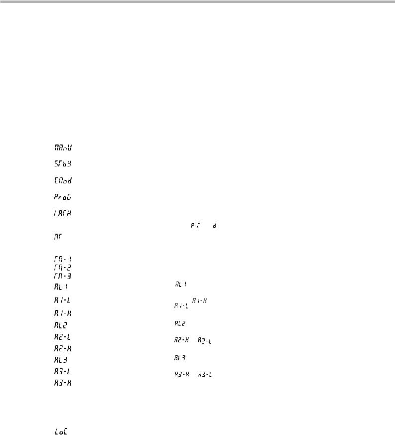
2-1 Parameter list
Parameters for the PXR are classified into operation parameters, and the first block, the second block and the third block parameters according to the frequency of use. The second and the third block parameters are used at initialization or when they are absolutely necessary.
Operation parameter
Parameter |
Parameter name |
Description |
Setting range and |
Parameter |
|
Reference |
display symbol |
|
factory default setting (*) |
mask DSP |
|
page |
|
|
|
|
||||
|
|
|
|
|
|
|
(PV) |
Measured temperature |
Displays the currently measured temperature |
Setting not allowed. |
dP13-64 |
See page 78 for the method |
|
(Measurement value) |
(Measurement value). |
|
|
of turning on/off PV. |
||
|
|
|
||||
|
|
|
|
|
|
|
(SV) |
Set temperature |
Displays the set temperature (Set value). |
0 to 100%FS (*: 0%FS) |
Mask not |
14 |
|
(Set value) |
|
|
allowed. |
|
||
|
|
|
|
|
|
|
Parameters of the first block
Parameter |
Parameter name |
Description |
|
Setting range and |
User’s |
Parameter |
Reference |
|
display symbol |
|
|
factory default setting (*) |
set value |
mask DSP |
page |
||
|
|
|
|
|||||
|
|
|
|
|
|
|
|
|
|
Manual mode |
Switches between Auto and Manual operation |
oN: Manual mode |
|
dP13-32 |
15 |
||
|
selection |
modes. |
|
|
oFF: Auto mode* |
|
||
|
|
|
|
|
|
|||
|
|
|
|
|
|
|
|
|
|
Standby setting |
Switches between RUN and Standby for |
oN: Control standby |
|
dSP1-1 |
16 |
||
|
|
control. |
|
|
(Output: OFF, Alarm: OFF) |
|
||
|
|
|
|
|
oFF: Control RUN* |
|
|
|
|
Remote/local |
Switches between remote and local operations. |
rEM: Remote |
|
dp13-8 |
17 |
||
|
setting |
|
|
|
LoCL: Local |
|
||
|
|
|
|
|
|
|
||
|
|
|
|
|
|
|
|
|
|
Ramp-soak |
|
|
|
oFF: Stop* |
|
|
18 |
|
control |
|
|
|
rUn: Start |
|
dSP1-2 |
|
|
|
|
|
|
HLd: Hold |
|
|
|
|
|
|
|
|
|
|
|
|
|
Alarm latch |
Cancels the alarm latch. |
|
|
0: Keeps the alarm latch.* |
|
dSP1-4 |
19 |
|
cancel |
|
|
|
1: Opens up the alarm latch. |
|
||
|
|
|
|
|
|
|
||
|
Auto-tuning |
Used for setting the constants for , |
, and |
0: OFF (Resets the auto-tuning or does |
|
|
|
|
|
|
by auto-tuning. |
|
|
not use it.)* |
|
|
|
|
|
|
|
|
1: ON (Performs the auto-tuning in the |
|
dSP1-8 |
20 |
|
|
|
|
|
SV standard type.) |
|
||
|
|
|
|
|
|
|
|
|
|
|
|
|
|
2: ON (Performs the auto-tuning in |
|
|
|
|
|
|
|
|
low PV type (SV value-10%FS).) |
|
|
|
|
|
|
|
|
|
|
|
|
|
Timer 1 display |
Displays the remaining time of timer 1. |
- (Unit: seconds) |
|
dSP1-16 |
21 |
||
|
Timer 2 display |
Displays the remaining time of timer 2. |
- (Unit: seconds) |
|
dSP1-32 |
21 |
||
|
Timer 3 display |
Displays the remaining time of timer 3. |
- (Unit: seconds) |
|
dSP1-64 |
21 |
||
|
Set value of |
Sets the value at which |
is displayed |
When the alarm type is absolute value: |
|
dSP1-128 |
22 * |
|
|
alarm 1 |
alarm 1 is detected. |
when alarm type 1 |
0 to 100%FS (*:10) |
|
|||
|
|
|
is 0 to 15, or 32 to |
|
|
|
|
|
|
Lower limit |
Sets the lower limit value at |
When the alarm type is deviation: |
|
|
22 * |
||
|
34, and |
or |
|
dSP2-1 |
||||
|
value of alarm 1 |
which alarm 1 is detected. |
|
|||||
|
is displayed |
-100 to 100%FS (*:10) |
|
|
|
|||
|
Upper limit |
Sets the upper limit value at |
|
|
|
|||
|
when alarm type 1 |
|
|
dSP2-2 |
22 * |
|||
|
value of alarm 1 |
which alarm 1 is detected. |
|
|
||||
|
is 16 to 31. |
|
|
|
|
|
||
|
Set value of |
Sets the value during which |
is displayed |
When the alarm type is absolute value: |
|
dSP2-4 |
22 * |
|
|
alarm 2 |
alarm 2 is detected. |
|
|||||
|
when alarm type 2 is 0 |
0 to 100%FS (*:10) |
|
|
|
|||
|
Lower limit value |
Sets the lower limit value at |
to 15 or 32 to 34, and |
|
|
dSP2-8 |
22 * |
|
|
of alarm 2 |
which alarm 2 is detected. |
When the alarm type is deviation: |
|
||||
|
or |
is |
|
|
|
|||
|
Upper limit value |
Sets the upper limit value at |
displayed when alarm |
-100 to 100%FS (*:10) |
|
dSP2-16 |
22 * |
|
|
type 2 is 16 to 31. |
|
|
|||||
|
of alarm 2 |
which alarm 2 is detected. |
|
|
|
|
||
|
Set value of |
Sets the value at which |
is displayed |
When the alarm type is absolute value: |
|
dSP2-32 |
22 * |
|
|
alarm 3 |
alarm 3 is detected. |
|
|||||
|
when alarm type 3 is 0 |
0 to 100%FS (*:10) |
|
|
|
|||
|
Lower limit value |
Sets the lower limit value at |
to 15 or 32 to 34, and |
When the alarm type is deviation: |
|
dSP2-64 |
22 * |
|
|
of alarm 3 |
which alarm 3 is detected. |
or |
is |
|
|
|
|
|
Upper limit value |
Sets the upper limit value at |
displayed when alarm |
-100 to 100%FS (*:10) |
|
dSP2-128 |
22 * |
|
|
type 3 is 16 to 31. |
|
|
|||||
|
of alarm 3 |
which alarm 3 is detected. |
|
|
|
|
||
|
|
|
|
|
0: All settings are changeable both from |
|
dSP3-1 |
|
|
|
|
|
|
the face panel and via communication.* |
|
|
|
|
|
|
|
|
|
|
|
|
|
|
|
|
|
1: All settings are unchangeable from the |
|
|
|
|
|
|
|
|
face panel, but changeable via |
|
|
|
|
|
|
|
|
communication. |
|
|
|
|
|
|
|
|
2: Only the SV is changeable from the |
|
|
|
|
|
|
|
|
face panel, and all settings are |
|
|
|
|
|
Specifies whether or not to allow the change of |
changeable via communication. |
|
|
23 |
||
|
|
parameters. |
|
|
3: All settings are changeable from the |
|
|
|
|
|
|
|
|
|
|
||
|
|
|
|
|
face panel, but unchangeable via |
|
|
|
|
|
|
|
|
communication. |
|
|
|
|
|
|
|
|
4: All settings are unchangeable from the |
|
|
|
|
|
|
|
|
face panel or via communication. |
|
|
|
|
|
|
|
|
5: Only the SV is changeable from the |
|
|
|
|
|
|
|
|
face panel, but all settings are unchangeable |
|
|
|
|
|
|
|
|
via communication. |
|
|
|
Note: The parameters for which * is marked with the page number in Reference page are related to Remedies of “4” on page 79.
7
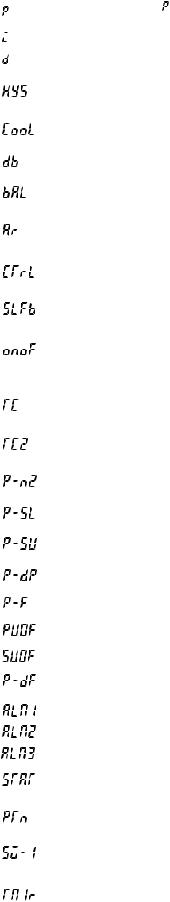
Parameters of the second block
Note: The parameters for which * is marked with the page number in
Reference page are related to Remedies of “4” on page 79.
Parameter |
Parameter name |
Description |
Setting range and factory |
User’s |
Parameter |
Reference |
|
display symbol |
default setting (*) |
set value |
mask DSP |
page |
|||
|
|
|
|
|
|
|
|
|
Proportional band |
Set to 0.0 to select the ON/OFF |
0.0 to 999.9% (*: 5.0) |
|
dSP3-2 |
24 |
|
|
|
control (Two-position control). |
|
|
|
|
|
|
|
|
|
|
|
|
|
|
Integral time |
|
0 to 3200 seconds (*: 240) |
|
dSP3-4 |
25 |
|
|
|
|
|
|
|
|
|
|
Derivative time |
|
0.0 to 999.9 seconds (*: 60.0) |
|
dSP3-8 |
26 |
|
|
|
|
|
|
|
|
|
|
Hysteresis range for |
Sets the hysteresis for ON/OFF |
0 to 50%FS (*: equivalent of 1.0°C) |
|
dSP3-16 |
27 * |
|
|
ON/OFF control |
control. |
|
|
|
||
|
|
|
|
|
|
|
|
|
Cooling-side proportional |
|
0.0 to 100.0 (*: 1.0) |
|
dSP3-32 |
28 |
|
|
band coefficient |
|
|
|
|
|
|
|
|
|
|
|
|
|
|
|
|
|
|
|
|
|
|
|
Cooling-side |
|
-50.0 to +50.0 (*: 0.0) |
|
dSP3-64 |
29 |
|
|
proportional band shift |
|
|
|
|
|
|
|
|
|
|
|
|
|
|
|
Output convergence |
|
-100 to 100% |
|
dSP3-128 |
30 |
|
|
value |
|
(*: single 0.0, dual 50.0) |
|
|
|
|
|
|
|
|
|
|
||
|
|
|
|
|
|
|
|
|
Anti-reset windup |
|
0 to 100%FS (*: 100%FS) |
|
dSP4-1 |
30 * |
|
|
|
|
|
|
|
|
|
|
Control algorithm |
Selects the control algorithm. |
PID: Runs normal PID control.* |
|
dSP4-2 |
31 |
|
|
|
|
FUZY: Runs PID control with fuzzy logic. |
|
|
|
|
|
|
|
SELF: Runs PID control with self-running. |
|
|
|
|
|
|
|
|
|
|
|
|
|
PV (Measured |
Sets the PV stable range for the self- |
0 to 100%FS (*: 2%FS) |
|
dSP4-4 |
35 * |
|
|
value) stable range |
tuning operation. |
|
|
|
|
|
|
Setting HYS |
Selects the hysteresis operation at |
oFF: Starts the two-position control at the |
|
dSP4-8 |
|
|
|
(Hysteresis) mode |
ON/OFF control. |
values of SV+HYS/2 and SV-HYS/2. |
|
|
36 |
|
|
|
|
on: Starts the two-position control at the values |
|
|
|
|
|
|
|
of SV and SV+HYS, or SV and SV-HYS.* |
|
|
|
|
|
|
|
|
|
|
|
|
|
Cycle time of |
Not shown at 4-20mA DC output |
RLY, SSR: 1 to 150 seconds |
|
dSP4-16 |
37 |
|
|
control output 1 |
|
(*: Contact output = 30, |
|
|
|
|
|
|
|
SSR/SSC-driven output = 2) |
|
|
|
|
|
|
|
|
|
|
|
|
|
Cycle time of |
|
1 to 150 seconds (*: 30) |
|
dSP4-32 |
38 |
|
|
control output 2 |
|
|
|
|
|
|
|
(cooling-side) |
|
|
|
|
|
|
|
|
|
|
|
|
|
|
|
Input signal code |
Set this parameter when changing |
1 to 16 (*: specified by customer while |
|
dSP4-64 |
39 |
|
|
|
the types of temperature sensors. |
ordering) Note 1 |
|
|
|
|
|
Lower limit of |
|
-1999 to 9999 (*: specified by customer |
|
dSP4-128 |
40 |
|
|
measuring range |
|
while ordering) Note 1 |
|
|
|
|
|
Upper limit of |
|
-1999 to 9999 (*: specified by customer |
|
dSP5-1 |
40 |
|
|
measuring range |
|
while ordering) Note 1 |
|
|
|
|
|
Setting the decimal |
|
0 to 2 (*: specified by customer while |
|
dSP5-2 |
42 |
|
|
point position |
|
ordering) Note 1 |
|
|
|
|
|
°C / °F selection |
|
°C / °F |
|
dSP5-4 |
40 |
|
|
PV (Measured |
|
-10 to 10%FS (*: 0) |
|
dSP5-8 |
43 |
|
|
value) offset |
|
|
|
|
|
|
|
|
|
|
|
|
|
|
|
SV (Setting value) offset |
|
-50 to 50%FS (*: 0) |
|
dSP5-16 |
44 * |
|
|
Time constant of |
|
0.0 to 900.0 seconds (*: 5.0) |
|
dSP5-32 |
45 |
* |
|
|
|
|
||||
|
input filter |
|
|
|
|
|
|
|
|
|
|
|
|
|
|
|
|
|
|
|
|
|
|
|
Alarm type 1 |
Sets the types of alarm operations. |
0 to 34 (*: 0/5) |
|
dSP5-64 |
46 |
|
|
|
|
|
|
|
|
|
|
Alarm type 2 |
Sets the types of alarm operations. |
0 to 34 (*: 0/9) |
|
dSP5-128 |
46 |
|
|
|
|
|
|
|
|
|
|
Alarm type 3 |
Sets the types of alarm operations. |
0 to 34 (*: 0) |
|
dSP6-1 |
46 |
|
|
|
|
|
|
|
|
|
|
Status display of |
|
- (*: OFF) |
|
dSP6-2 |
50 |
|
|
ramp-soak |
|
|
|
|
|
|
|
|
|
|
|
|
|
|
|
|
|
|
|
|
|
|
|
Selecting ramp- |
Selects ramp-soak patterns. |
1: Performs 1st to 4th segments.* |
|
dSP6-4 |
49 |
|
|
soak execute type |
2: Performs 5th to 8th segments. |
|
|
|
||
|
|
|
3: Performs 1st to 8th segments. |
|
|
|
|
|
|
|
|
|
|
|
|
|
1st target value |
Sets the 1st target SV of ramp-soak |
Within the SV limit. (*: 0%FS) |
|
dSP6-8 |
50 |
* |
|
/Switching-SV |
operation. / Selected at switching- |
|
|
|
|
|
|
value |
SV function for DI1 |
|
|
|
|
|
|
|
|
|
|
|
|
|
|
First ramp segment |
Sets the first ramp segment time. |
0 to 99h59m (*: 0.00) |
|
dSP6-16 |
50 |
|
|
time |
|
|
|
|
|
|
8

Note: The parameters for which * is marked with the page number in
Reference page are related to Remedies of “4” on page 79.
Parameter |
Parameter name |
Description |
Setting range and factory |
User’s |
Parameter |
Reference |
||
display symbol |
default setting (*) |
set value |
mask DSP |
page |
||||
|
|
|||||||
|
|
|
|
|
|
|
|
|
|
1st soak segment |
Sets the 1st soak segment time. |
0 to 99h59m (*: 0.00) |
|
dSP6-32 |
50 |
|
|
|
time |
|
|
|
|
|
||
|
|
|
|
|
|
|
|
|
|
2nd target SV |
Sets the 2nd target SV of ramp-soak |
Within the SV limit. (*: 0%FS) |
|
dSP6-64 |
50 |
* |
|
|
|
operation. |
|
|
|
|
||
|
|
|
|
|
|
|
||
|
|
|
|
|
|
|
|
|
|
2nd ramp segment |
Sets the 2nd ramp segment time. |
0 to 99h59m (*: 0.00) |
|
dSP6-128 |
50 |
|
|
|
time |
|
|
|
|
|
||
|
|
|
|
|
|
|
|
|
|
2nd soak segment |
Sets the 2nd soak segment time. |
0 to 99h59m (*: 0.00) |
|
dSP7-1 |
50 |
|
|
|
time |
|
|
|
|
|
||
|
|
|
|
|
|
|
|
|
|
3rd target SV |
Sets the 3rd target SV of ramp-soak |
Within the SV limit. (*: 0%FS) |
|
dSP7-2 |
50* |
||
|
|
|
||||||
|
|
operation. |
|
|
|
|
|
|
|
|
|
|
|
|
|
|
|
|
3rd ramp segment |
Sets the 3rd ramp segment time. |
0 to 99h59m (*: 0.00) |
|
dSP7-4 |
50 |
|
|
|
time |
|
|
|
|
|
||
|
|
|
|
|
|
|
|
|
|
3rd soak segment |
Sets the 3rd soak segment time. |
0 to 99h59m (*: 0.00) |
|
dSP7-8 |
50 |
|
|
|
time |
|
|
|
|
|
||
|
|
|
|
|
|
|
|
|
|
4th target SV |
Sets the 4th target SV of ramp-soak |
Within the SV limit. (*: 0%FS) |
|
dSP7-16 |
50 |
* |
|
|
|
operation. |
|
|
|
|
||
|
|
|
|
|
|
|
||
|
|
|
|
|
|
|
|
|
|
4th ramp segment |
Sets the 4th ramp segment time. |
0 to 99h59m (*: 0.00) |
|
dSP7-32 |
50 |
|
|
|
time |
|
|
|
|
|
||
|
|
|
|
|
|
|
|
|
|
4th soak segment |
Sets the 4th soak segment time. |
0 to 99h59m (*: 0.00) |
|
dSP7-64 |
50 |
|
|
|
time |
|
|
|
|
|
||
|
|
|
|
|
|
|
|
|
|
5th target SV |
Sets the 5th target SV of ramp-soak |
Within the SV limit. (*: 0%FS) |
|
dSP7-128 |
50 |
* |
|
|
|
operation. |
|
|
|
|
||
|
|
|
|
|
|
|
||
|
|
|
|
|
|
|
|
|
|
5th ramp segment |
Sets the 5th ramp segment time. |
0 to 99h59m (*: 0.00) |
|
dSP8-1 |
50 |
|
|
|
time |
|
|
|
|
|
||
|
|
|
|
|
|
|
|
|
|
5th soak segment |
Sets the 5th soak segment time. |
0 to 99h59m (*: 0.00) |
|
dSP8-2 |
50 |
|
|
|
time |
|
|
|
|
|
||
|
|
|
|
|
|
|
|
|
|
6th target SV |
Sets the 6th target SV of ramp-soak |
Within the SV limit. (*: 0%FS) |
|
dSP8-4 |
50 |
* |
|
|
|
operation. |
|
|
|
|
||
|
|
|
|
|
|
|
||
|
|
|
|
|
|
|
|
|
|
6th ramp segment |
Sets the 6th ramp segment time. |
0 to 99h59m (*: 0.00) |
|
dSP8-8 |
50 |
|
|
|
time |
|
|
|
|
|
||
|
|
|
|
|
|
|
|
|
|
6th soak segment |
Sets the 6th soak segment time. |
0 to 99h59m (*: 0.00) |
|
dSP8-16 |
50 |
|
|
|
time |
|
|
|
|
|
||
|
|
|
|
|
|
|
|
|
|
7th target SV |
Sets the 7th target SV of ramp-soak |
Within the SV limit. (*: 0%FS) |
|
dSP8-32 |
50* |
||
|
|
|
||||||
|
|
operation. |
|
|
|
|
|
|
|
|
|
|
|
|
|
|
|
|
7th ramp segment |
Sets the 7th ramp segment time. |
0 to 99h59m (*: 0.00) |
|
dSP8-64 |
50 |
|
|
|
time |
|
|
|
|
|
||
|
|
|
|
|
|
|
|
|
|
7th soak segment |
Sets the 7th soak segment time. |
0 to 99h59m (*: 0.00) |
|
dSP8-128 |
50 |
|
|
|
time |
|
|
|
|
|
||
|
|
|
|
|
|
|
|
|
|
8th target SV |
Sets the 8th target SV of ramp-soak |
Within the SV limit. (*: 0%FS) |
|
dSP9-1 |
50* |
||
|
|
|
||||||
|
|
operation. |
|
|
|
|
|
|
|
|
|
|
|
|
|
|
|
|
8th ramp segment |
Sets the 8th ramp segment time. |
0 to 99h59m (*: 0.00) |
|
dSP9-2 |
50 |
|
|
|
time |
|
|
|
|
|
||
|
|
|
|
|
|
|
|
|
|
8th soak segment |
Sets the 8th soak segment time. |
0 to 99h59m (*: 0.00) |
|
dSP9-4 |
50 |
|
|
|
time |
|
|
|
|
|
||
|
|
|
|
|
|
|
|
|
|
Ramp-soak mode |
Selects the power-on start, repeat, and |
0 to 15 (*: 0) |
|
dSP9-8 |
50 |
|
|
|
|
standby functions for ramp-soak |
|
|
|
|
||
|
|
|
|
|
|
|
||
|
|
operations. |
|
|
|
|
|
|
|
|
|
|
|
|
|
|
|
Note 1: When a customer does not specify the settings while ordering, the following settings are selected as factory defaults.
Thermocouple input: Thermocouple K |
Measured range: 0 to 400°C |
Resistance bulb input: |
Measured range: 0 to 150°C |
Voltage/Current input: |
Scaling: 0 to 100% |
9

Parameters of the third block
Note: The parameters for which * is marked with the page number in
Reference page are related to Remedies of “4” on page 79
Parameter |
Parameter name |
|
|
|
|
|
|
Description |
Setting range and factory |
User’s |
Parameter |
Reference |
||
display symbol |
|
|
|
|
|
|
default setting (*) |
set value |
mask DSP |
page |
||||
|
|
|
|
|
|
|
|
|||||||
|
|
|
|
|
|
|
|
|
||||||
|
Control action |
|
Specifies control action and output at |
0 to 19 (*: specified by customer while |
|
dSP9-16 |
53 |
|
||||||
|
|
|
the input burn-out. |
ordering) Note 2 |
|
|
|
|
||||||
|
|
|
|
|
|
|
|
|||||||
|
SV (Setting value) |
|
Sets the lower limit of the SV. |
0 to 100%FS (*: 0%FS) |
|
dSP9-32 |
54 |
* |
||||||
|
lower limiter |
|
|
|
|
|
|
|
|
|
|
|
|
|
|
|
|
|
|
|
|
|
|
|
|
|
|
|
|
|
SV (Setting value) |
|
Sets the upper limit of the SV. |
0 to 100%FS (*: 100%FS) |
|
dSP9-64 |
54* |
|||||||
|
upper limiter |
|
|
|
||||||||||
|
|
|
|
|
|
|
|
|
|
|
|
|
|
|
|
Delay time 1 |
|
Delay time or timer value for alarm 1 relay. |
0 to 9999 seconds (*: 0) |
|
dSP9-128 |
55 |
|
||||||
|
Delay time 2 |
|
Delay time or timer value for alarm 2 relay. |
0 to 9999 seconds (*: 0) |
|
dP10-1 |
55 |
|
||||||
|
|
|
|
|
|
|
|
|
|
|
|
|
|
|
|
Delay time 3 |
|
Delay time or timer value for alarm 3 relay. |
0 to 9999 seconds (*: 0) |
|
dP10-2 |
55 |
|
||||||
|
|
|
|
|
|
|
|
|
|
|||||
|
Current transe display |
|
Displays the current detector input value for HB alarm. |
- |
|
|
dP10-4 |
57 |
|
|||||
|
|
|
|
|
|
|
|
|
|
|
|
|
|
|
|
HB (Set value of heater |
|
Sets the operation value that detects the |
0 to 50.0A (Setting to 0.0A turns off the |
|
dP10-8 |
57 |
|
||||||
|
break alarm) setting |
|
heater break. |
HB alarm.) (*: 0.0) |
|
|
|
|
||||||
|
|
|
|
|
|
|
||||||||
|
|
|
|
|
|
|
|
|
|
|
|
|
||
|
Alarm 1 hysteresis |
|
Sets the hysteresis range of ON and |
0 to 50%FS (*: 1) |
|
|
dP10-16 |
59* |
||||||
|
|
|
OFF of alarm 1. |
|
|
|||||||||
|
|
|
|
|
|
|
|
|
||||||
|
|
|
|
|
|
|
|
|
|
|||||
|
Alarm 2 hysteresis |
|
Sets the hysteresis range of ON and |
0 to 50%FS (*: 1) |
|
|
dP10-32 |
59* |
||||||
|
|
|
OFF of alarm 2. |
|
|
|||||||||
|
|
|
|
|
|
|
|
|
||||||
|
|
|
|
|
|
|
|
|
|
|
|
|
|
|
|
Alarm 3 hysteresis |
|
Sets the hysteresis range of ON and |
0 to 50%FS (*: 1) |
|
|
dP10-64 |
59 * |
||||||
|
|
|
OFF of alarm 3. |
|
|
|
||||||||
|
|
|
|
|
|
|
|
|
||||||
|
|
|
|
|
|
|
|
|
|
|
|
|
|
|
|
Alarm 1 options |
|
Sets the optional functions of alarms 1, 2 and |
000 to 111 (*: 000) |
|
|
dP10-128 |
60 |
|
|||||
|
|
3. |
|
|
|
|
|
|
|
|
|
|
||
|
|
|
|
|
|
|
|
|
|
|
|
|
||
|
|
|
|
|
|
|
|
|
|
|
|
|
|
|
|
Alarm 2 options |
|
|
|
|
|
|
|
000 to 111 (*: 000) |
|
|
dP11-1 |
60 |
|
|
|
|
|
|
|
|
|
|
|
|
||||
|
|
|
|
|
|
|
|
Alarm latch (1: use, 0: not use) |
|
|
|
|
|
|
|
|
|
|
|
|
|
|
|
|
|
|
|
|
|
|
|
|
|
|
|
|
Alarm of error status (1: use, 0: not use) |
|
|
|
|
|
|
|
|
Alarm 3 options |
|
|
|
|
|
000 to 111 (*: 000) |
|
|
dP11-2 |
60 |
|
||
|
|
|
|
|
|
|
|
|
||||||
|
|
|
|
|
De-energized output (1: use, 0: not use) |
|
|
|
||||||
|
|
|
|
|
|
|
|
|
||||||
|
|
|
|
|
|
|
|
|||||||
|
Lower limit for output 1 |
Sets the lower limit for output 1. |
-3.0 to 103.0% (*: -3.0) |
|
dP11-4 |
62 |
|
|||||||
|
|
|
|
|
|
|
|
|||||||
|
Upper limit for output 1 |
Sets the upper limit for output 1. |
-3.0 to 103.0% (*: 103.0) |
|
dP11-8 |
62 |
|
|||||||
|
|
|
|
|
|
|
|
|||||||
|
Lower limit for output 2 |
Sets the lower limit for output 2. |
-3.0 to 103.0% (*: -3.0) |
|
dP11-16 |
62 |
|
|||||||
|
|
|
|
|
|
|
|
|
|
|
||||
|
Upper limit for output 2 |
Sets the upper limit for output 2. |
-3.0 to 103.0% (*: 103.0) |
|
dP11-32 |
62 |
|
|||||||
|
|
|
|
|
|
|
|
|
||||||
|
Output limit types |
Sets the limit types of outputs 1 and 2 |
0 to 15 (*: 0) |
|
|
dP11-64 |
63 |
|
||||||
|
|
(breaking the limit, or maintained |
|
|
|
|
|
|||||||
|
|
within the limit). |
|
|
|
|
|
|
||||||
|
|
|
|
|
|
|
|
|
|
|
|
|||
|
Output value (MV) |
Displays the value of output 1. |
- |
|
|
dP11-128 |
64 |
|
||||||
|
display |
|
|
|
|
|
|
|
|
|
|
|
|
|
|
|
|
|
|
|
|
|
|
|
|
|
|
|
|
|
Output value (MV) |
Displays the value of output 2. |
- |
|
|
dP12-1 |
64 |
|
||||||
|
display |
|
|
|
|
|
|
|
|
|
|
|
|
|
|
|
|
|
|
|
|
|
|
|
|
|
|
|
|
|
RCJ (Cold junction |
Sets the cold junction compensation |
ON: Performs the RCJ (Cold junction |
|
dP12-2 |
|
|
|||||||
|
compensation) |
function to ON/OFF. |
compensation).* |
|
|
|
65 |
|
||||||
|
setting |
|
|
|
|
|
|
|
OFF: Does not perform the RCJ (Cold |
|
|
|
||
|
|
|
|
|
|
|
|
|
|
|
|
|||
|
|
|
|
|
|
|
|
|
junction compensation). |
|
|
|
|
|
|
|
|
|
|
|
|
|
|
|
|
|
|
|
|
|
PV gradient |
|
|
|
|
|
|
|
0.001 to 2.000 (*: 1.000) |
|
dP12-4 |
|
|
|
|
|
|
|
|
|
|
|
|
|
|
|
|
|
|
|
User-definable zero |
Shifts the zero point of input value. |
-50 to 50%FS (*: 0) |
|
|
dP12-8 |
66 |
* |
||||||
|
adjustment |
|
|
|
|
|
|
|
|
|
|
|
|
|
|
|
|
|
|
|
|
|
|
||||||
|
User-definable span |
Shifts the span of input value. |
-50 to 50%FS (*: 0) |
|
|
dP12-16 |
66 |
* |
||||||
|
adjustment |
|
|
|
|
|
|
|
|
|
|
|
|
|
|
|
|
|
|
|
|
|
|
|
|
|
|
|
|
|
DI1 (Digital input 1) |
Sets the DI1 operations. |
0 to 12 (*: 0=OFF) |
|
|
dP12-32 |
67 |
|
||||||
|
operation |
|
|
|
|
|
|
|
|
|
|
|
|
|
|
|
|
|
|
|
|
|
|
|
|
|
|
|
|
|
DI2 (Digital input 2) |
Sets the DI2 operations. |
0 to 12 (*: 0=OFF) |
|
|
dP12-64 |
67 |
|
||||||
|
operation |
|
|
|
|
|
|
|
|
|
|
|
|
|
|
|
|
|
|
|
|
|
|
|
|
|
|||
|
Station No. |
Sets the station No. for |
0 to 255 (Setting to |
does not start the |
|
dP12-128 |
70 |
|
||||||
|
|
communication. |
communications function.) (*: 1) |
|
|
|
|
|||||||
|
|
|
|
|
|
|
|
|
||||||
|
Parity setting |
Sets the parity for communication. |
0: Odd parity* |
1: Even parity |
|
dP13-1 |
71 |
|
||||||
|
|
(The baud rate is fixed at 9600bps. |
2: No parity |
|
|
|
|
|
||||||
|
|
|
|
|
|
|
|
|
|
|
|
|
|
|
Note 2: The following settings are selected as factory defaults depending on the model you order.
Seventh digit = Y model: 0 |
Seventh digit = A model: 4 |
10
Note: The parameters for which * is marked with the page number in
Reference page are related to Remedies of “4” on page 79.
Parameter |
Parameter name |
Description |
Setting range and factory |
User’s |
Parameter |
Reference |
|
display symbol |
default setting (*) |
set value |
mask DSP |
page |
|||
|
|
||||||
|
|
|
|
|
|
|
|
|
Communication |
Switches communication protocols |
0 : Z-ASCII |
|
dP13-2 |
72 |
|
|
between Modbus and ASCII |
|
|||||
|
protocol setting |
1 : Modbus (RTU) |
|
|
|
||
|
|
|
|
|
|
|
|
|
Re-transmission |
Sets the type of signals to be outputted |
Setting range |
|
dP13-4 |
73 |
|
|
output type setting |
from re-transmission output. |
0 : PV / 1 : SV / 2 : MV/ 3 : DV (* : 0) |
|
|
||
|
|
|
|
||||
|
|
|
|
|
|
|
|
|
Re-transmission |
Re-transmission output scaling setting |
Setting range |
|
dP13-4 |
74 |
|
|
output scaling base |
on the base side |
-100.0 to 100.0% (*: 0.0) |
|
|
||
|
side setting |
|
|
|
|
|
|
|
|
|
|
|
|
|
|
|
Re-transmission |
Re-transmission output scaling on the |
Setting range |
|
dP13-4 |
74 |
|
|
output scaling span |
span side |
-100.0 to 100.0% (*: 100.0) |
|
|
||
|
side setting |
|
|
|
|
|
|
|
|
|
|
|
|
|
|
|
Remote SV input |
Shifts the zero point of input value. |
-50 to 50%FS (*: 0) |
|
dP13-16 |
75 |
|
|
zero adjustment |
|
|
|
|
||
|
|
|
|
|
|
||
|
|
|
|
|
|
|
|
|
Remote SV input |
Shifts the span point of input value. |
-50 to 50%FS (*: 0) |
|
dP13-16 |
75 |
|
|
span adjustment |
|
|
|
|
||
|
|
|
|
|
|
||
|
|
|
|
|
|
|
|
|
Remote SV input |
Sets the filter constant of remote SV |
0.0 to 900.0 seconds (*: 0.0) |
|
dP13-16 |
76 |
|
|
filter constant |
input value. |
|
|
|
||
|
|
|
|
|
|||
|
|
|
|
|
|
|
|
|
Remote SV input |
Displays remote SV input value. |
- |
|
dP13-16 |
77 |
|
|
value display |
|
|
|
|
||
|
|
|
|
|
|
||
|
|
|
|
|
|
|
|
|
Parameter mask |
Sets whether or not to display each |
0 to 255 (*: specified by customer |
|
– |
78 |
|
|
|
parameter. |
while ordering) |
|
|
||
|
|
|
|
|
|
|
11

2-2 Basic operations
Just after power-on:
The display below appears just after power-on.
|
|
|
|
°C |
C1 |
C2 |
AL1 |
AL2 |
AL3 |
PV |
|
|
|
|
SV |
|
|
|
|
|
SEL |
|
|
|
PXR |
|
|
|
|
Status at delivery <In Auto mode>
|
|
|
°C |
C1 |
C2 AL1 |
AL2 |
AL3 |
PV |
|
|
|
SV |
|
|
|
|
SEL |
|
<In Manual mode> |
PXR |
|
|
How to switch parameters:
The figure below shows the basic operations for the PXR.
Just after power-on |
Setting parameters |
(PV/SV displayed)
|
|
|
|
°C |
|
PV |
|
C1 |
C2 AL1 |
AL2 |
AL3 |
|
|
|
PV |
|
|
|
Not operated |
SV |
Changes SV. |
|
|
|
|
for 30 seconds. |
|
SV |
|
|
|
|
|
|
|
|
|
|
|
|
|
|
|
SEL |
|
|
|
|
|
PXR |
|
|
|
|
|
SEL |
|
SEL |
|
SEL |
|
SEL |
(approx. |
(approx. |
|
(approx. |
PV |
PV |
|
|
|
|
||||
1 second) |
3 seconds) |
|
5 seconds) |
|
|
|
|
|
|
|
|
SV |
SV |
|
|
|
|
|
|
SEL |
Parameters of the |
Parameters of the |
Parameters of the |
first block |
second block |
third block |
Pressing and holding the 


 keys makes the value increase or decrease fast.
PV
SV
Basic operations for the PXR (In Auto mode)
12

|
Just after power-on |
||
|
(PV/MV displayed) |
||
|
|
|
°C |
Not operated |
C1 |
C2 AL1 AL2 |
AL3 |
|
|
SEL |
|
for 30 seconds. |
PV |
|
|
Changes MV. SV |
|
SEL |
|
|
|
SEL |
|
|
|
|
|
|
PXR |
|
|
SEL |
|
|
SEL |
(approx. |
|
|
(approx. |
1 second) |
|
|
3 seconds) |
(PV/SV displayed) |
Setting parameters |
|
|
|
|
°C |
|
|
C1 |
C2 AL1 |
AL2 |
AL3 |
|
PV |
PV |
|
|
|
|
SV |
|
|
|
|
|
|
SV |
|
|
Changes SV. |
|
|
|
|
|
|
|
|
|
SEL |
|
|
|
|
PXR |
|
|
|
|
|
|
|
|
SEL |
|
SEL |
|
|
|
PV |
PV |
|
|
|
(approx. |
|
|
|
|
|
5 seconds) |
SV |
SV |
|
|
|
|
|
|
SEL |
Parameters of the |
Parameters of the |
Parameters of the |
first block |
second block |
third block |
Basic operations for the PXR (In Manual mode)
PV
SV
Pressing and holding the 


 keys makes the value increase or decrease fast.
How to set values:


 key: One press increases the value by 1.
Press and hold this key to increase the value fast. 

 key: One press decreases the value by 1.
Press and hold this key to decrease the value fast.
How to register the set data:
By pressing the SEL key, the displayed values are registered.
Note that the SV (SV0) will be registered in 3 seconds without any operation.
13

2-3 Parameter functions and method of settings
Method of setting the SV (Setting value)
[Description]
•The SV is a target value for control.
•Any SV that is outside of the range set in the parameters of 


 (lower limit) and


 (upper limit) of the third block cannot be set. (See page 54.)
Related parameters: 

 (page 54)


 (page 54)
[Setting example] Changing the SV from 250°C to 1195°C
Display |
Operating procedure |
1.Press the 

 or
or 

 keys to display

 .
.
SV
|
2. |
will be registered in the SV (SV0) in three seconds. After that, the controller will operate |
SV |
|
with the SV being 1195. |
|
|
|
|
|
14


 Manual mode setting (Settings: oFF/on)
[Description]
•This parameter switches the control mode between Auto and Manual.
•During Manual operation, the decimal point is kept on at the far right in the SV display section.
•During Manual operation, auto tuning or self tuning is not done. If the mode is switched to Manual while auto or self tuning is being done, the tuning is forcibly terminated. The PID parameter remains the same in such cases.
•Manual operation output is not limited by MV limit.
•Manual operation can be carried out during standby operation.
•The operation output set value during Auto/Manual operation mode and manual mode is stored in non-volatile memory. It is kept stored even if a power interruption occurs. When the power is turned on again, the state before the power interruption is resumed.
•The following table lists the operation output at the time of switching between Auto and Manual..
Auto → Manual |
Manual → Auto |
Balanceless bumpless |
MV output according to |
(Switches to manual mode, |
PID operation |
holding the MV value just |
(Sudden change may occur |
before the switching.) |
to the MV value.) |
|
|
|
|
|
Single |
|
|
|
|
Manual |
Manual |
|
output |
|
|
|
|
|
|
|
|
|
|
||
MV |
|
|
Manual |
|
|
|
|
PID |
|
|
MV1 |
|
|
Error |
|
calculation AUTO |
|
Auto |
Limit |
Standby |
OUT1 |
||
|
|
output |
|||||
|
|
|
Dual |
|
|
|
|
|
|
|
|
|
|
|
|
|
MAnU |
P-n1 |
output |
|
|
Error |
|
|
Auto |
Limit |
Standby |
OUT2 |
|||
|
= |
= |
|
output |
|||
|
ON |
Single |
MV2 |
|
|
|
|
|
|
|
|
|
|
|
|
|
|
|
Manual |
|
|
|
|
[Setting example] Switching to manual mode
Display |
Operating procedure |
1.Press and hold the SEL key for one second, and 


 is displayed.
2.Press the |
|
|
key once, and the current set value ( |
) on the SV display section starts flickering. |
||
|
SEL |
|||||
3.Press the |
|
|
or the |
|
keys to display . |
|
|
|
|
|
|||
4.Press the |
|
|
key once, and the manual lamp at the lower right corner comes on, indicating that |
|||
|
SEL |
|||||
the mode has been switched to Manual.
5.To display operation status, press and hold the SEL key for two seconds.
15


 Standby setting (Settings: oFF/on)
[Description]
•This parameter switches the control between RUN and Standby.
•During standby, the control output and the alarm output stay OFF, like the standby for ramp-soak operation.
•While the alarm with a hold is selected, the hold function takes effect after changing the Standby setting from ON to OFF.
•


 is displayed during the standby for ramp-soak operations or the controller changes to the standby state in case of the occurrence of errors.
•The other operations are the same as those of the rampsoak standby.
•The setting of ON/OFF for standby is saved after poweroff.
•When the standby is set to ON during the auto-tuning, self-tuning, and ramp-soak operations, those operations will stop. (The PID constant will not be renewed.) Even through it is set to OFF later, the auto-tuning, self-tuning, and ramp-soak operations will not be re-started.
•During standby, the ON-delay timer is reset. When returning to RUN from the standby state, the timer will start from the beginning.
[Setting example] Starting the control
Display |
|
|
|
|
|
Operating procedure |
||||||||||
|
|
|
|
|
|
|
|
|
|
|||||||
|
|
|
1.Press and hold the |
|
|
key for one second. |
|
|
|
|||||||
|
|
|
|
|
|
|
|
|||||||||
SEL |
|
|
|
|||||||||||||
|
|
|
will be displayed. Then press the |
|
key once. |
|||||||||||
|
|
|
|
|||||||||||||
|
|
|
2.Press the |
|
|
|
key once. |
|
|
|
||||||
|
|
|
|
|
|
|
|
|
||||||||
|
|
|
|
|
|
|
|
|
||||||||
|
SEL |
|
|
|
||||||||||||
|
|
|
The current setting ( |
) flashes on the SV display. |
||||||||||||
|
|
|
||||||||||||||
|
|
|
3.Press the |
|
|
or |
|
|
keys to display . |
|
|
|
||||
|
|
|
|
|
|
|
|
|
|
|
||||||
|
|
|
|
|
|
|||||||||||
|
|
|
4.Press the |
|
|
key once. The standby state for control is selected. (control output and all the alarm |
||||||||||
|
|
|
|
|
|
|
||||||||||
|
|
|
|
|
|
|
||||||||||
SEL |
||||||||||||||||
|
|
|
outputs: OFF) |
|
|
|
|
|
|
|
|
|
||||
|
|
|
|
|
|
|
|
|
|
|
|
|||||
|
|
|
5.If you want to display the operation status, press and hold the |
|
key for two seconds. The value |
|||||||||||
|
|
|
|
|||||||||||||
SEL |
||||||||||||||||
|
|
|
on the SV display will flash, indicating the standby status. |
|||||||||||||
|
|
|
||||||||||||||
|
|
|
|
|
|
|
|
|
|
|
|
|
|
|
|
|
16


 Local/remote operation setting (Setting range: LoCL/rEM) (Option)
[Description]
•This parameter is used to switch between local and remote operations.
Set value |
Operation |
Performs local operation.
Performs remote operation.
(“

 ” and the set value (SV) are displayed alternately in the SV display section on the front face while in remote operation.)
Related parameters: 


 (page 75)


 (page 75)
 (page 76)
(page 77)
* Local operation: Control by SV set by the keys on the front face, ramp-soak operation, SV selection determined by digital input, and SV setting via communication
* Remote operation: Control by SV determined by Remote SV input
[Setting example] Switching to remote operation
Display |
|
|
|
|
|
|
Operating procedure |
|||
|
|
1.Press and hold the |
|
key for one second. |
||||||
|
|
|
||||||||
SEL |
||||||||||
|
|
will be displayed on the PV display section. |
||||||||
|
|
|||||||||
|
|
2.Press the |
|
|
keys to display |
. |
||||
|
|
|
|
|||||||
|
|
|
|
|||||||
|
|
|||||||||
|
|
3.Press the |
|
key once. |
|
|
||||
|
|
|
|
|
|
|||||
|
|
|
|
|
|
|||||
SEL |
|
|
||||||||
|
|
The current setting ( |
) in the SV display section flickers. |
|||||||
|
|
|||||||||
4.Press the 

 keys to display

 .
.
5.Press the SEL key once. Flickering stops and the operation is switched to remote.
6.To display the operation status, press and hold the SEL key for two seconds.
17


 Ramp-soak control (Settings: oFF/rUn/hLd) (Option)
[Description]
•This function automatically changes the SV (Setting value) according to the program pattern set in advance as shown in the right line graph. Up to eight pairs of rampsoak operation can be programmed.
•The first ramp starts at the PV (Measured value) that is the one just before running the program.
•The program can also automatically run at power-on (Power-on starting function). Refer to the parameter of 


 (page 47).
Up to SV-8
SV-3 |
|
|
|
|
|
|
|
|
|
SV-2 |
|
|
|
|
ramp Third |
soak Third |
|
|
|
SV-1 |
|
|
ramp Second |
soak Second |
|
|
|
||
SV-4 |
|
soak First |
ramp Fourth |
|
|
||||
PV |
First ramp |
Fourth soak |
|
||||||
|
|
TM1S |
TM2S |
TM3S |
|
TM4S |
Up to TM8s |
||
|
TM1r |
|
TM2r |
|
TM3r |
TM4r |
Up to TM8r |
||
Related parameters: |
(page 50) |
|
|
to |
(page 50) |
|
to |
(page 50) |
|
to |
(page 50) |
|
(page 50) |
|
|
(page 49) |
|
Ramp: the section in which the SV changes toward the target value.
Soak: the section in which the SV is the target value, and remains unchanged.
[Setting example] Starting the ramp-soak operation
Display |
Operating procedure |
|||
|
|
1.Press and hold the |
|
key for one second. |
|
|
|
||
SEL |
||||
|
|
will be displayed on the PV display. |
||
|
|
|||
|
|
|
|
|
2.Press the 

 key to display


3.Press the SEL key once.
The current setting (

 ) flashes on the SV display.
4.Press the |
|
or |
|
keys to display |
. |
|
|
|
|||||
5.Press the |
|
|
key once. Then, the program will start according to the ramp-soak pattern that is |
|||
|
SEL |
|||||
|
|
|||||
set in advance. |
|
|
|
|||
6.If you want to display the operation status, press and hold the SEL key for two seconds.
18


 Canceling the alarm latch (Setting range: 0/1) (Option)
[Description]
• This parameter cancels the alarm latch when it is latching. |
Related parameters: |
|
|
to |
(page 60) |
[Setting example] Opening up the alarm latch
Display |
|
|
Operating procedure |
||
|
|
|
1.Press and hold the |
|
key for one second. |
|
|
|
SEL |
||
|
|
|
will be displayed on the PV display. |
||
|
|
|
|||
|
|
|
|
|
|
2.Press the 

 key to display


 .
.
3.Press the SEL key once.
The current setting ( |
) flashes on the SV display. |
|||||
4.Press the |
|
or |
|
|
keys to display . |
|
|
|
|
||||
5.Press the |
|
|
key once. |
|||
|
SEL |
|||||
 will stop flashing and will change to
 in a few seconds.
6.If you want to display the operation status, press and hold the SEL key for two seconds.
19

Auto-tuning function (Settings: 0/1/2)
[Description]
[Note]
If the controller is powered off during auto-tuning, this makes the auto-tuning ineffective with each parameter of  ,
,  , and
, and  unchanged. To start the auto-tuning operation, set
 to “1” or “2” again.
•To suspend the auto-tuning, set 
 to “0”. This makes the auto-tuning cancel with each parameter of
  ,
,  , and
, and
 unchanged.
•Once the parameters of ,
,  , and
, and  are set automatically by the auto-tuning, those parameters are stored in the
controller even after it is powered off. Therefore, it is not necessary to execute the auto-tuning again.
•By setting 
 to “1” or “2” , the auto-tuning operation starts, and at the end of the tuning,
  will be displayed automatically to
 .
.
•After the auto-tuning operation, the controller starts to operate at the automatically set values of ,
,  , and
, and  .
.
•A decimal point at the right end of the SV display flashes during auto-tuning.
•There are two codes for AT: Setting code [1]: SV standard type
Performs the auto-tuning based on the SV. Setting code [2]: Low PV type
Performs the auto-tuning based on the
SV-10%FS.
[Note]
Since ON/OFF control is performed during auto-tun- ing, overshoot against the SV may occur. To reduce the overshoot, execute the auto-tuning operation with the setting code [2] (Low PV) selected.
•The auto-tuning can be executed both just after power-on and in a control or stable status.
Related parameters:
 (page 24)
 (page 25)
 (page 26)

 (page 30)


 (page 28)
[Setting example] Setting the auto-tuning operation to 1
Display |
Operating procedure |
1.Press and hold the SEL key for one second.


 will be displayed on the PV display.
2.Press the 

 key to display
 .
.
3.Press the SEL key once.
The current setting ( ) flashes on the SV display.
4.Press the |
|
or |
|
keys to display . |
|
|
|
||||
5.Press the |
|
|
key once. will stop flashing and the auto-tuning will start. During auto-tuning, |
||
|
SEL |
||||
|
|
||||
a decimal point at the right end of the SV display flashes.
6.When the auto-tuning finishes properly, a decimal point stops flashing, and the set values of ,
,  , and
, and  parameters change. When the auto-tuning finishes abnormally, a decimal point stops flashing, but the set values of
 ,
,  , and
, and  parameters remain unchanged.
7.If you want to display the operation status, press and hold the SEL key for two seconds.
20
|
, |
|
, |
|
Displaying ON-delay alarm or the remaining time of timers |
|
|
|
|
|
|
|
|
|
|
|
(unit: seconds) (Option) |
|
|
|
|
|
[Description]
•These parameters display the remaining time of Timers 1, 2 and 3.
•The remaining time of the ON/OFF-delay timer is counted down. When the counter shows  , the alarm relay is closed.
•During count-down, if the PV changes to the value of the temperature at which the alarm is set to OFF, or if “DI” for the timer is set to OFF, the counter is reset, and the alarm relay is opened.
• 


 display parameter
PV
SV |
Remaining time (seconds) |
|
[Setting example] Displaying ON-delay alarm or the remaining time of timers
Display |
|
|
|
|
|
|
|
|
Operating procedure |
|
|
|
|
||
|
|
|
|
|
|
|
|
|
|
|
|
|
|
||
|
|
|
1.Press and hold the |
|
|
key for one second. |
|
|
|
|
|||||
|
|
|
SEL |
|
|
|
|
||||||||
|
|
|
|
|
|
|
|
|
|||||||
|
|
|
will be displayed. |
|
|
|
|
|
|||||||
|
|
|
|
|
|
|
|
||||||||
|
|
|
2.Press the |
|
|
key to display |
. |
|
|
|
|
||||
|
|
|
|
|
|
|
|
|
|||||||
|
|
|
|
|
|
|
|
|
|||||||
|
|
|
|
|
|
|
|
|
|||||||
|
|
|
The remaining time of timer 1 will be displayed. |
|
|
|
|
||||||||
|
|
|
|
|
|
|
|||||||||
|
|
|
3.Press the |
|
|
or |
|
|
|
keys to display the remaining time of |
, |
and |
. |
||
|
|
|
|
|
|
|
|
||||||||
|
|
|
4.If you want to display the operation status, press and hold the |
|
key for two seconds. |
||||||||||
|
|
|
|
||||||||||||
|
|
|
SEL |
||||||||||||
|
|
|
|
||||||||||||
|
|
|
|
|
|
|
|
|
|
|
|
|
|
|
|
21

Setting alarm |
(Setting range: |
1, 2 and 3 |
Absolute value alarm: 0 to 100%FS |
|
|
Upper limit of alarm |
|
1, 2 and 3 |
Deviation value alarm: -100 to 100%FS ) |
Lower limit of |
}(Option) |
alarm 1,2 and 3 |
|
[Description]
• |
These parameters are used to for settings of alarm 1, 2 |
[Note] |
|
|
|
|||||
|
and 3. |
|
|
|
|
|
Setting codes (12 to 15) cannot be selected in alarm |
|||
• |
When the alarm type ( |
|
, |
or |
) is set to |
type 1 and 3 ( |
/ |
). |
|
|
|
0 to 15, alarms 1, 2 and 3 ( |
, |
and |
) can be |
|
|
|
|
||
|
set. |
|
|
|
|
|
Related parameters: |
, |
, |
(page 46) |
• |
When the alarm type ( |
|
, |
or |
) is set to |
|
, |
, |
(page 59) |
|
|
any value other than 0 to 15, the upper and lower limits |
|
, |
, |
(page 55) |
|||||
|
of alarm 1, 2 and 3 ( |
, |
, |
, |
, |
, |
|
, |
, |
(page 60) |
|
) can be set. |
|
|
|
|
|
|
|
|
|
[Setting example] Setting the operation value of alarm 2 to -10°C
Display |
Operating procedure |
1.Press and hold the SEL key for one second.


 will be displayed on the PV display.
2.Press the 

 key to display

 .
.
3.Press the SEL key once.
The current setting ( ) flashes on the SV display.
4.Press the |
|
or |
|
keys to display |
. |
|
||
|
|
|
||||||
5.Press the |
|
|
key once. |
will stop flashing and will be registered for |
. After that, the |
|||
|
SEL |
|||||||
|
|
|||||||
controller will operate with the operation value of alarm 2 being -10°C. |
|
|||||||
6.If you want to display the operation status, press and hold the SEL key for two seconds.
22

Key lock (Setting range: 0−5)
[Description]
•This parameter makes the set values of parameters unchangeable. However, the parameter name and the set values can be displayed.
•To reset the key lock, change to  .
.
•Even when the key lock is set, control and alarm functions can operate properly.
•There are six levels of the key lock:
 : Unlocked (reset)
 : All settings are unchangeable from the controller, but changeable via communication.
 : Only the SV is changeable from the controller, and all settings are changeable via communication.
 : All settings are changeable from the controller, but unchangeable via communication.
 : All settings are unchangeable from the controller or via communication.
 : Only the SV is changeable from the controller, but all settings are unchangeable via communication.
[Setting example] Setting the key lock to “2”
Display |
Operating procedure |
1.Press and hold the SEL key for one second.


 will be displayed on the PV display.
2.Press the 

 key to display

 .
.
3.Press the SEL key once.
The current setting ( ) flashes on the SV display.
4.Press the 

 or
or 

 keys to display
  .
.
5.Press the |
|
key once. will stop flashing and will be registered for |
. After that, any |
SEL |
|||
|
setting other than the SV cannot be changed from the front panel.
6.If you want to display the operation status, press and hold the SEL key for two seconds.
23


 Proportional band (Setting range: 0.0 to 999.9% of the measured range)
[Description]
• To select the ON/OFF control (two-position control), set 
 to 0.0. It is not necessary to set
  and
and 
 .
.
•
 can be automatically set by the auto-tuning operation.
•When 
 is too small, control will be unstable, and when
 is too large, the response will be delayed.
•Set the hysteresis of the ON/OFF control (two-position control) in the parameter 


 .
.
•If auto-tuning is run after the ON/OFF control is selected, the ON/OFF control changes to the PID control. To keep the ON/OFF control selected, do not execute the autotuning.
[Setting example] Changing the proportional band from 5.0% to 15.0%
Display |
|
|
|
|
|
|
|
|
|
Operating procedure |
|||||
|
|
|
|
|
|
|
|||||||||
|
|
|
1.Press and hold the |
|
|
key for three seconds. |
|||||||||
|
|
|
|
|
|||||||||||
SEL |
|||||||||||||||
|
|
|
will be displayed on the PV display. |
|
|
|
|||||||||
|
|
|
|
|
|
||||||||||
|
|
|
2.Press the |
|
|
|
key once. |
|
|
|
|
||||
|
|
|
|
|
|
|
|
|
|
||||||
|
|
|
|
|
|
|
|
|
|
||||||
SEL |
|
|
|
|
|||||||||||
|
|
|
The current setting ( |
) flashes on the SV display. |
|||||||||||
|
|
|
|||||||||||||
|
|
|
3.Press the |
|
|
|
or |
|
|
keys to display |
. |
|
|
||
|
|
|
|
|
|
|
|
|
|
|
|||||
|
|
|
|||||||||||||
|
|
|
4.Press the |
|
|
key once. |
will stop flashing and will be registered for . After that, the |
||||||||
|
|
|
|
|
|
||||||||||
|
|
|
|
|
|
||||||||||
|
SEL |
||||||||||||||
|
|
|
controller will operate with |
being 15.0%. |
|
|
|
||||||||
|
|
|
|
|
|
||||||||||
|
|
|
5.If you want to display the operation status, press and hold the |
|
key for two seconds. |
||||||||||
|
|
|
|
||||||||||||
SEL |
|||||||||||||||
|
|
|
|
|
|
|
|
|
|
|
|
|
|
|
|
|
|
|
|
|
|
|
|
|
|
|
|
|
|
|
|
24

Integral time (Setting range: 0 to 3200 seconds)
[Description]
• |
can be set automatically by the auto-tuning operation. |
• |
When |
is set to 0, the integral operation does not start. |
• |
can also be set manually. |
• |
When |
is set to 0.0, this makes the setting of ineffec- |
|
|
|
tive. |
|
[Setting example] Changing the integral time from 240 seconds to 600 seconds
Display |
Operating procedure |
1.Press and hold the SEL key for three seconds.
 will be displayed on the PV display.
2.Press the 

 key to display
  .
.
3.Press the SEL key once. |
|
The current setting ( |
) flashes on the SV display. |
4.Press the 

 or
or 

 keys to display

 .
.
5.Press the |
|
key once. |
will stop flashing and will be registered for . After that, the |
|
SEL |
||||
controller will operate with |
being |
seconds. |
||
6.If you want to display the operation status, press and hold the SEL key for two seconds.
25
Loading...