

Page 1
Installation
alla
n
Inst
and Operation
and O
tion
eratio
FRITZ!Powerline 520E Set
Page 2

Table of Contents
Symbols and Highlighting . . . . . . . . . . . . . . . . . . . . . . . . 4
1 FRITZ!Powerline 520E . . . . . . . . . . . . . . . . . . . . . . . . . . . . 5
2 Before You Connect the FRITZ!Powerline . . . . . . . . . . . . . 6
2.1 Package Contents . . . . . . . . . . . . . . . . . . . . . . . . . . . . . . . . . . . . . . . . 6
2.2 Security Instructions . . . . . . . . . . . . . . . . . . . . . . . . . . . . . . . . . . . . . . 6
2.3 LEDs, Buttons and Network Port . . . . . . . . . . . . . . . . . . . . . . . . . . . . . 7
2.4 Integrated Socket. . . . . . . . . . . . . . . . . . . . . . . . . . . . . . . . . . . . . . . . . 8
3 Connecting the FRITZ!Powerline. . . . . . . . . . . . . . . . . . . . 9
3.1 Connecting FRITZ!Powerline 520E Set . . . . . . . . . . . . . . . . . . . . . . . . 9
3.2 Expanding a FRITZ!Powerline Network . . . . . . . . . . . . . . . . . . . . . . . 10
3.3 Connecting Powerline Adapters from Other Manufacturers . . . . . . 11
3.4 Connecting Multiple Network Devices . . . . . . . . . . . . . . . . . . . . . . . 11
4 Security in the Powerline Network. . . . . . . . . . . . . . . . . 12
4.1 Encryption . . . . . . . . . . . . . . . . . . . . . . . . . . . . . . . . . . . . . . . . . . . . . 12
4.2 Changing the Network Password . . . . . . . . . . . . . . . . . . . . . . . . . . . 12
5 Application Examples. . . . . . . . . . . . . . . . . . . . . . . . . . . 16
5.1 Internet Connection for All Network Devices . . . . . . . . . . . . . . . . . . 16
5.2 Networking Computers . . . . . . . . . . . . . . . . . . . . . . . . . . . . . . . . . . . 17
5.3 Game Consoles on the Internet Connection or in the Home Network
5.4 TVs and Stereo Systems in the Network. . . . . . . . . . . . . . . . . . . . . . 19
. 18
6 The AVM FRITZ!Powerline Program. . . . . . . . . . . . . . . . . 20
7 Factory Settings . . . . . . . . . . . . . . . . . . . . . . . . . . . . . . . 22
2
Page 3

8 Power-saving Features of FRITZ!Powerline 520E. . . . . . 23
9 Optimizing Transmission Capacity. . . . . . . . . . . . . . . . . 24
10 FAQs. . . . . . . . . . . . . . . . . . . . . . . . . . . . . . . . . . . . . . . . . 25
10.1 Multiple Powerline Networks in Once Circuit. . . . . . . . . . . . . . . . . . 25
10.2 FRITZ!Powerline across Various Phases in the Power Supply . . . . . 25
10.3 Electricity Meter, Fuse Box, GFCI Ground Fault Circuit Interrupter . 26
10.4 Adapters from Other Manufacturers in the Powerline Network . . . 26
10.5 Kinds of Devices on the Powerline Adapter . . . . . . . . . . . . . . . . . . . 26
11 Powerline: Technical Background . . . . . . . . . . . . . . . . . 27
12 Electromagnetic Interference . . . . . . . . . . . . . . . . . . . . . 28
13 Comparison with other Network Technologies . . . . . . . 29
14 Technical Specifications. . . . . . . . . . . . . . . . . . . . . . . . . 31
15 Customer Service . . . . . . . . . . . . . . . . . . . . . . . . . . . . . . 32
15.1 Information in the Internet . . . . . . . . . . . . . . . . . . . . . . . . . . . . . . . . 32
15.2 Support from the Support Team . . . . . . . . . . . . . . . . . . . . . . . . . . . . 32
15.3 Support by E-mail . . . . . . . . . . . . . . . . . . . . . . . . . . . . . . . . . . . . . . . 32
15.4 Manufacturer’s Warranty. . . . . . . . . . . . . . . . . . . . . . . . . . . . . . . . . . 33
Legal Notice. . . . . . . . . . . . . . . . . . . . . . . . . . . . . . . . . . . 34
Legal Notice . . . . . . . . . . . . . . . . . . . . . . . . . . . . . . . . . . . . . . . . . . . . 34
Declaration of CE Conformity . . . . . . . . . . . . . . . . . . . . . . . . . . . . . . 35
Disposal Information . . . . . . . . . . . . . . . . . . . . . . . . . . . . . . . . . . . . . 36
Index . . . . . . . . . . . . . . . . . . . . . . . . . . . . . . . . . . . . . . . . 37
3
Page 4
Symbols and Highlighting
Symbols and emphasized text are used to mark certain information in
this manual.
Symbols
This symbol marks useful hints and tips.
This symbol indicates important instructions that must be
observed to avoid malfunctions.
Highlighting
Highlighting Example
Quotation marks designate elements in the
user interface, path entries, and names of
folders and files
Blue, underlined text designates addresses
to be entered in the browser
Blue text designates links and references within this manual
Bold type emphasizes important words Do not click ...
“Home Network”
“C:\Pictures”
“Info”
fritz.box
see page 34
4
Page 5
FRITZ!Powerline 520E
Power/DSL
Internet
Festnetz
WLAN
Info
1 FRITZ!Powerline 520E
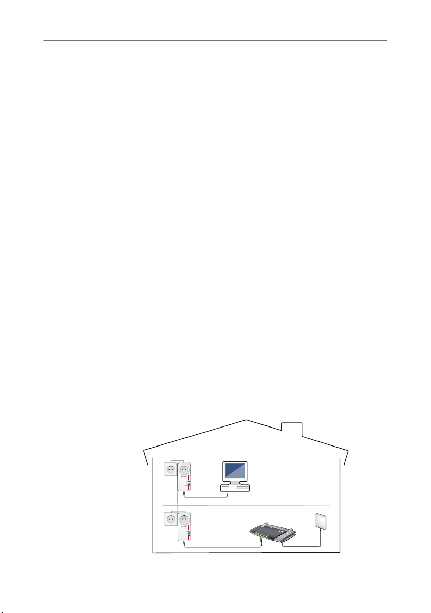
FRITZ!Powerline 520E allows data to be transmitted over the electrical
wiring in your home.
With FRITZ!Powerline 520E you connect network devices like computers, game consoles and televisions via electrical wiring in what is
known as a powerline network. The powerline network can then be
connected to your Internet router, Internet connection and home network.
In a powerline connection over electrical wiring a network device, for
instance your computer, is connected to a FRITZ!Powerline 520E with
a network cable. An additional network device, for instance your Internet router, is connected with the second FRITZ!Powerline 520E in the
same way. Each FRITZ!Powerline 520E is plugged into a power outlet
in your home to provide the connection between the two devices.
With the powerline connection to the Internet router the connected
computer receives access to the Internet.
The FRITZ!Powerline 520E Set includes two adapters, which require
no setup. Upon delivery both FRITZ!Powerline 520E are configured
such that connections are safely encrypted from the outset. Additional FRITZ!Powerline adapters, including adapters from other manufacturers, are easy to integrate into the powerline network to extend coverage.
FRITZ!Powerline 520E is the right solution whenever a network connection is necessary, but laying network cables is either impossible or
undesirable. FRITZ!Powerline 520E is an economical solution for institutions as well, like offices, schools or hotels.
5
Page 6

Before You Connect the FRITZ!Powerline
2 Before You Connect the FRITZ!Powerline
• Check the contents of your FRITZ!Powerline 520E package.
• Read the security instructions before connecting FRITZ!Powerline
520E.
2.1 Package Contents
• two FRITZ!Powerline 520E
• two network cables
• printed product information
2.2 Security Instructions
• Always plug FRITZ!Powerline 520E directly into a wall
outlet. If at all possible, do not plug FRITZ!Powerline
520E into sockets on extension cords or multiple socketoutlets (power outlet strips).
If you would like to use multi-outlet power strips, then
plug FRITZ!Powerline 520E into the wall outlet and the
multi-outlet strip in FRITZ!Powerline 520E’s integrated
socket.
• Insert FRITZ!Powerline 520E in outlets located in a dry
place that is free of dust and protected from direct sunlight.
• FRITZ!Powerline 520E may heat up during operation.
This is normal. The FRITZ!Powerline 520Es comply with
the required safety regulations.
• Avoid operation in the direct vicinity of a radiator or
heating unit and provide for sufficient ventilation. The
slits and openings on the housing are for ventilation and
must not be blocked or covered.
• The FRITZ!Powerline 520E is intended for indoor use only.
• Never let liquids get inside the FRITZ!Powerline 520E.
Otherwise, electric shocks or short circuits may result.
6
Page 7
LEDs, Buttons and Network Port
• Do not open the FRITZ!Powerline 520E housings. The de-
vices contain hazardous components and should only
be opened by authorized repair technicians.
• Remove the device from the mains before cleaning.
Clean the device using only a moist cloth.
2.3 LEDs, Buttons and Network Port
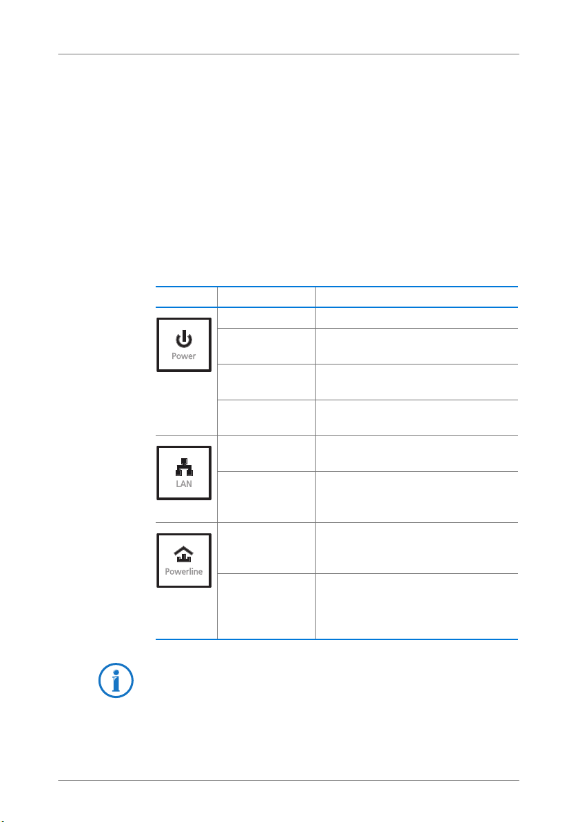
LEDs
FRITZ!Powerline 520E has three LEDs that display the operating status:
LED Condition Meaning
on FRITZ!Powerline has electrical power
flashing FRITZ!Powerline is restarting or confi-
flashing (every
15 seconds)
off FRITZ!Powerline has no electrical
on The network port (LAN port) is occup-
off No network cable is connected, or
on FRITZ!Powerline is connected with
off FRITZ!Powerline did not detect any
guring security settings
FRITZ!Powerline is on standby
power
ied
the device connected to the network
cable is switched off
the powerline network and sending
or receiving data
compatible powerline devices or
detect any devices that use the same
network key
If you do not want to use the LEDs, you can switch them off in
the AVM FRITZ!Powerline program or in the user interface of a
connected FRITZ!Box.
7
Page 8

Integrated Socket
Button
FRITZ!Powerline 520E has two buttons:
Button Function
Reset button Restores the factory settings to
Security button Integrates into an existing
LAN Port
FRITZ!Powerline 520E has a network port (LAN port) for computers and other network devices.
This port is a gigabit Ethernet port.
2.4 Integrated Socket
The integrated socket on the FRITZ!Powerline 520E replaces
the electrical outlet where the FRITZ!Powerline 520E is
plugged in.
If you need a multi-outlet strip (power outlet strip) at this location, plug the multi-outlet strip into FRITZ!Powerline 520E’s
integrated socket. The integrated socket is equipped with a
mains filter for low-interference powerline connections.
FRITZ!Powerline.
powerline network.
Always operate the multi-outlet strip on FRITZ!Powerline’s integrated socket. Do not connect FRITZ!Powerline to a multioutlet strip.
8
Page 9
Connecting the FRITZ!Powerline
FRITZ!Box
3 Connecting the FRITZ!Powerline
With FRITZ!Powerline 520E Set you can set up a powerline network
and expand it with further adapters.
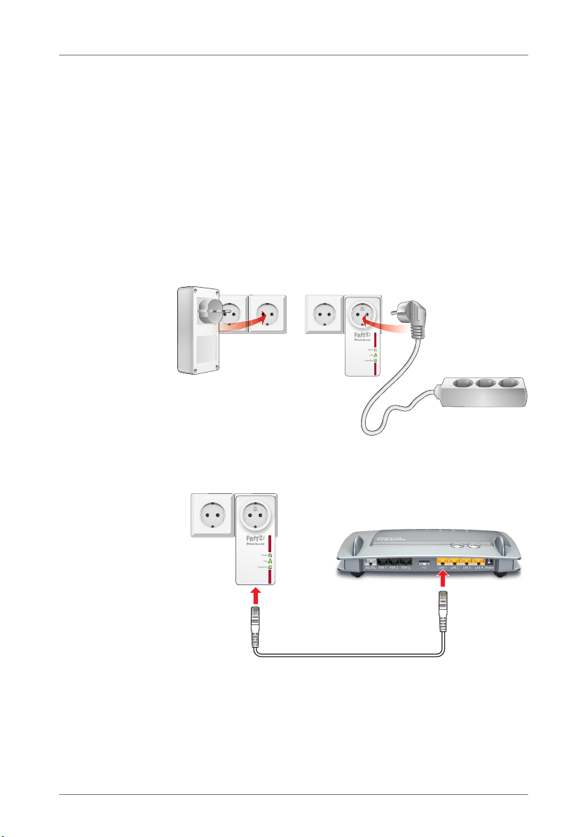
3.1 Connecting FRITZ!Powerline 520E Set
1. Insert the first FRITZ!Powerline adapter in an outlet near
your FRITZ!Box.
Always plug FRITZ!Powerline directly into a wall outlet. If
you would also like to connect a multi-outlet strip, connect it to FRITZ!Powerline 520E’s integrated socket.
2. Connect your FRITZ!Box to the FRITZ!Powerline adapter
with a LAN cable.
3. Plug the second FRITZ!Powerline adapter into any outlet
in your home.
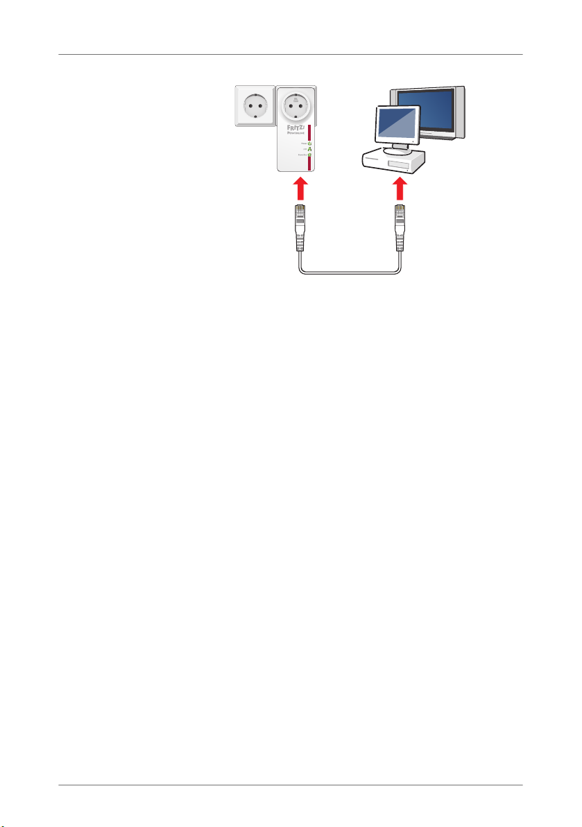
4. Use a LAN cable to connect a computer or another net-
work device (such as a television) to the second
FRITZ!Powerline adapter.
9
Page 10
Expanding a FRITZ!Powerline Network
Now you can use the Internet connection of the FRITZ!Box on
the network device.
3.2 Expanding a FRITZ!Powerline Network
An existing FRITZ!Powerline powerline network can be expanded with additional FRITZ!Powerline adapters.
1. Insert the new FRITZ!Powerline in an electrical outlet
near a plugged in FRITZ!Powerline that is already part of
the powerline network.
2. Press the “Security” button for one second to establish a
new connection.
3. Within two minutes, press the “Security” button on an
existing FRITZ!Powerline already connected in your network and hold it down until the “Powerline” LED stops
flashing.
4. Now plug the new FRITZ!Powerline into the desired pow-
er outlet.
The new FRITZ!Powerline is now safely integrated in your network.
10
Page 11

Connecting Powerline Adapters from Other Manufacturers
3.3 Connecting Powerline Adapters from Other Manufacturers
In a FRITZ!Powerline network you can also integrate powerline
adapters from other manufacturers. The prerequisite for this
is that they are powerline devices of the 500 and 200-Mbit/s
category.
1. Plug the powerline adapter from the other manufacturer
into any outlet in your home.
2. Press the “Security” button on a FRITZ!Powerline already
integrated in the network for one second in order to start
transmission of the network password to the powerline
adapter from the other manufacturer.
Always establish a secure powerline connection. This
keeps you from inadvertently integrating device in a
neighboring powerline network.
3. Within 2 minutes, press the “Security” button on the
powerline adapter from the other manufacturer to apply
the new network password.
For detailed instructions, see the documentation of the
powerline adapter or contact the manufacturer.
The powerline adapter now connects with the FRITZ!Powerline
network. Generally an LED indicates when this process has
been completed.
3.4 Connecting Multiple Network Devices
You can also operate multiple network devices on
FRITZ!Powerline if you connect a standard switch or hub to
the network port on FRITZ!Powerline. All of the network devices connected to the switch or hub can then exchange data
with all other devices in the local network.
11
Page 12

Security in the Powerline Network
4 Security in the Powerline Network
FRITZ!Powerline 520E is delivered with a preset individual network
password. This protects connections within the FRITZ!Powerline from
the outset.
The network password within a powerline network has two functions:
• The network password is the code word for exclusive access to
the network. It identifies the adapter in the network.
Up to four powerline networks can exist within a single circuit.
They are separated from each other by their network passwords.
• The network password is used to encrypt the user data during
data transmission.
4.1 Encryption
FRITZ!Powerline uses AES-128 Bit encryption. This encryption
method is used both to identify FRITZ!Powerline in the powerline network and for encryption during data transmission.
Both adapters from the FRITZ!Powerline Set are delivered with
a preset individual network password. From the outset this
guarantees secure connections in the FRITZ!Powerline network. Additional FRITZ!Powerline adapters are integrated into
the network safely and securely at the push of a button.
4.2 Changing the Network Password
The network password should be changed whenever there
are concerns about security or whenever one larger network
is to be divided into two or more smallers ones.
There are two ways you to change the network password of a
powerline network if necessary:
• using the button: a random new network password is
generated automatically
• using the AVM FRITZ!Powerline program: specify your
own network password
12
Page 13

Changing the Network Password
Changing the Network Password by Button
Plug all FRITZ!Powerline adapters in any outlet in your home.
For this operation it makes sense to plug all adapters that are
supposed to receive the new network password next to each
other in a multi-outlet strip.
1. Plug the first two adapters into the sockets, and press
the “Security” button on both adapters for 12 seconds,
until all LEDs briefly turn off.
Now the FRITZ!Powerline adapters restart and each one
automatically assigns itself a randomly chosen network
password.
2. Press the “Security” button on one of the two adapters
for a second in order to start transmission of the new
network password.
The “Power” LED begins flashing.
3. Within 2 minutes, press the “Security” button on the
other adapter so that it can receive the new network
password.
Now the powerline connection is established with the
new network password. The process is concluded as
soon as the “Powerline” LEDs on both adapters stop
flashing.
4. Proceed as follows for every additional adapter that is to
receive the new network password:
Plug the adapter into a socket and press briefly the
“Security” button on the adapter. Within 2 minutes,
press the “Security” button on an adapter that already
has the new network password.
13
Page 14

Changing the Network Password
Changing the Network Password in the AVM FRITZ!Powerline
Program
1. Plug both FRITZ!Powerline adapters into outlets in your
home.
2. Use a network cable to connect one FRITZ!Powerline
adapters to a computer on which the AVM
FRITZ!Powerline program is installed.
3. Restart the AVM FRITZ!Powerline software and click the
icon of the FRITZ!Powerline that is not connected with
the computer.
The “FRITZ!Powerline Device Profile” window opens.
4. Enter any password you like in the “New network pass-
word” field and then click “OK”.
The “Set Network Password” window opens.
5. Enter the device password of the FRITZ!Powerline in the
“Device password” field and then click “OK”. The device
password of the adapter is printed on the sticker on the
base of the adapter housing.
Now FRITZ!Powerline will restart. As soon as the “Power”
LED stops flashing, the device has been restarted.
6. Next, go to the AVM FRITZ!Powerline program and dou-
ble-click the icon of the FRITZ!Powerline connected with
the computer.
The “FRITZ!Powerline Device Profile” window opens.
7. In the “New network password” field, enter the same
password you entered before for the first adapter.
8. Click “OK”.
Now the FRITZ!Powerline connection is established with
the new network password. The process is concluded as
soon as the “Powerline” LEDs on both adapters stop
flashing.
14
Page 15

Changing the Network Password
9. If there are more than two adapters in your network, then
the adapters that still have the old network password
will no longer be visible in the AVM FRITZ!Powerline program. In order to change their passwords as well, proceed as follows for each individual adapter:
Connect the adapter with the computer on which the
AVM FRITZ!Powerline program is installed and repeat
steps 6 through 8.
15
Page 16

Application Examples
Power/DSL
Internet
Festnetz
WLAN
Info
5Application Examples
The network devices connected in a network can exchange data among
each other and share network resources. Computers exchange data,
and share an Internet connection or a printer. The stereo system has
access to the central music collection, and the TV plays back video on
demand movies.
The following sections introduce several examples of how powerline
networks can look.
5.1 Internet Connection for All Network Devices
Network devices like computers, game consoles or televisions
are scattered over different rooms or even different floors of
your home. But generally there is only one Internet connection.
With FRITZ!Powerline you use the electrical wiring to connect all
devices with the Internet connection. In contrast to a wireless
16
Page 17

Networking Computers
network, this type of connection is not limited by structural
components like reinforced concrete or clay plaster, delivers
high transmission speeds and can be set up easily and economically.
5.2 Networking Computers
Computers connected with each other in a network can exchange data among each other and share hard drives or printers. Portable computers (laptop, notebook, tablet, etc.) can
be integrated into the home network temporarily.
With FRITZ!Powerline 520E you connect your computers via
electrical wiring in a powerline network.
17
Page 18

Game Consoles on the Internet Connection or in the Home Network
Power/DSL
Internet
Festnetz
WLAN
Info
5.3 Game Consoles on the Internet Connection or in the Home Network
With FRITZ!Powerline 520E you can integrate your game console into your network. If the network is connected to the Internet, you can play against users all over the world and
download game add-ons.
18
Page 19

TVs and Stereo Systems in the Network
Power/DSL
Internet
Festnetz
WLAN
Info
5.4 TVs and Stereo Systems in the Network
With FRITZ!Powerline 520E you can integrate your TV and your
stereo system into your network. When the network is connected with the Internet, the TV can use services like video on
demand, IP TV or services available in the Internet like YouTube and Flickr. The stereo system can receive web radio stations. Both devices also enjoy access to the collections of
photographs, videos and music available in the home network, which can be accessed on network storage.
19
Page 20

The AVM FRITZ!Powerline Program
6The AVM FRITZ!Powerline Program
For FRITZ!Powerline there is the AVM FRITZ!Powerline program, a user
interface for the FRITZ!Powerline network. The program offers you an
overview of the FRITZ!Powerline adapters and the adapters from other
manufacturers used in the network. An individual device profile can
be displayed for each adapter.
Download for Free
You can download AVM FRITZ!Powerline from the Internet free
of change from www.avm.de/en/powerline
Operating Systems
The program is available for the Windows 7, Vista und XP operating systems.
Features
• Graphical overview of all powerline adapters in the net-
work
.
• Additional powerline adapters can be added to the se-
cure powerline network
• Support in locating the best outlet
• LEDs can be switched on and off
• Energy savings through reduced throughput rates on the
network port
• Additional network encryption options
• Naming the adapters in the network
20
Page 21

The AVM FRITZ!Powerline Program
• Display of the individual device profile for each adapter
• Factory settings can be restored to each adapter
• Firmware updates of visible FRITZ!Powerline adapter
When you use FRITZ!Powerline in a FRITZ!Box home network,
the FRITZ!Box user interface gives you additional information
about the network.
21
Page 22

Factory Settings
7 Factory Settings
The adapters from the FRITZ!Powerline Set are delivered with preset
values for the adapter name, LED switching, power-saving function
(green mode) and network password settings. These four settings can
be changed as needed. There are two ways to restore the factory settings later.
Restoring Factory Settings with the “Reset” Button
1. Plug FRITZ!Powerline into an outlet.
2. Press the “Reset” button on the adapter and hold it
down for ca. two seconds. Use a pointed object to do
this, for instance a paper clip or a mechanical pencil,
since the button is recessed in the top of the housing to
keep it from being pressed by accident.
All LEDs go out for a moment and then the adapter will restart. As soon as the “Power” LED stops flashing, the procedure has been concluded.
Restoring Factory Settings with AVM FRITZ!Powerline
1. Plug FRITZ!Powerline into an outlet.
2. Use a network cable to connect FRITZ!Powerline to a
computer on which the “AVM FRITZ!Powerline” program
is installed.
3. Start the “AVM FRITZ!Powerline” program and double-
click the icon of the FRITZ!Powerline.
The “FRITZ!Powerline Device Profile” window opens.
4. Click the “Reset” button and then “OK”.
All LEDs go out for a moment and then the adapter will restart. As soon as the “Power” LED stops flashing, the procedure has been concluded.
22
Page 23

Power-saving Features of FRITZ!Powerline 520E
8 Power-saving Features of FRITZ!Powerline 520E
FRITZ!Powerline is equipped with modern power-saving features and
adjusts its energy consumption to the given state of operation.
Maximum Power Consumption
• in normal operation: less than 3 W
• in standby: less than 0.5 W
Standby Mode
FRITZ!Powerline automatically switches to standby mode approximately five minutes after the connected network device
has been switched off. The LEDs on the adapter switch off as
well.
Computers that can be started over the network (Wake on
LAN) are not switched off completely, so FRITZ!Powerline
does not switch to standby operation. To allow standby operation of the adapter in spite of this, you must either disable
the Wake on LAN function, or completely cut off the computer
from the power supply using a multi-outlet strip with its own
power switch.
Green Mode
The data rate on the network port of a FRITZ!Powerline adapter amounts to 1 Gbit/s. This data rate can be limited to
100 Mbit/s for each adapter in order to reduce the energy
consumption under load by up to 1 watt.
This limit is configured in the AVM FRITZ!Powerline program.
The setting for limiting data rates is called “Green Mode”.
For many applications in the home network a net data rate of
100 Mbit/s is sufficient.
23
Page 24

Optimizing Transmission Capacity
9 Optimizing Transmission Capacity
The power mains and the installed wiring are not designed for fast data transmission. However, if you follow the tips in this chapter, with
FRITZ!Powerline you can use the power outlet as a fast data port.
Finding the Ideal Power Outlet
The power mains does not offer shielded transmission, which
is generally the case for computer network cabling. Thus every branch, every socket and every switch on the way between two stations reduces transmission capacity. The shorter and more direct route over the electrical wiring, the higher
the transmission capacity.
In the AVM FRITZ!Powerline program the utilizable transmission capacity is displayed for each FRITZ!Powerline to help
you determine the ideal power outlet.
Avoiding Multi-Outlet Strips
Multi-outlet strips have two disadvantages:
• they constitute a branch and thus reduce transmission
capacity
• devices plugged into the multi-outlet strip that operate
in parallel can interfere with the powerline signal
Therefore the FRITZ!Powerline should be operated directly at
a wall outlet rather than at a multi-outlet strip to allow a higher transmission capacity.
Multi-outlet strips with surge protection should never be used
in front of a powerline adapter. The filters implemented for
surge protection can block the powerline signal completely.
Using the Integrated Socket
If there is only one wall outlet available, plug FRITZ!Powerline
into the wall outlet. Plug a multi-outlet strip into the socket
integrated into the FRITZ!Powerline. The integrated socket is
equipped with an internal power line filter. This filter blocks
interfering signals that may be emitted by other electronic devices on the line.
24
Page 25

FAQs
10 FAQs
This section presents answers to questions that may arise about
powerline adapters and powerline networks.
10.1 Multiple Powerline Networks in Once Circuit
Can multiple powerline networks exist in a single circuit?
Multiple FRITZ!Powerline networks can exist within a one circuit.
A powerline network consists of multiple adapters, all of
which use the same network password. The network password is the code word for exclusive access to the network. It
identifies the adapter in the network, and is also used to encrypt the user data. The network password ensures that the
network users can communicate securely and without interference.
Up to four powerline networks can exist within a single circuit. Each network uses its own individual network password.
No network interferes with the communication of another network.
10.2 FRITZ!Powerline across Various Phases in the Power Supply
Can FRITZ!Powerline be used across different phases of the
power supply?
Yes, home networking with FRITZ!Powerline is possible even
when the adapters are used in different phases (phase conductors) of the home’s power supply.
FRITZ!Powerline routes the transmission data to the electrical
wiring as high-frequency signals. This process is called modulation. During a phase shift the powerline signal shifts from
one phase to another as soon as the phase conductors run
parallel over a certain distance. Since this is the case in almost all buildings, FRITZ!Powerline can also be used across
different phases.
25
Page 26

Electricity Meter, Fuse Box, GFCI Ground Fault Circuit Interrupter
10.3 Electricity Meter, Fuse Box, GFCI Ground Fault Circuit Interrupter
Can a powerline connection extend over an electricity meter,
fuse box or GFCI?
The signal of powerline adapters can be received even on the
other side of an electricity meter, fuse box or GFCI (or RCCB:
residual-current circuit breaker)–even by unauthorized users
like neighbors. However, data traffic in your FRITZ!Powerline
network is protected from unauthorized access. The
FRITZ!Powerline network is secured upon delivery with an individual network password (128 Bit-AES key).
Most powerline adapters from other manufacturers allow data
exchange over powerline with no more than a standard, preset
network password. However, this does not protect access to
the network and data transmission. Use the “Security” button
to establish a secure connection as soon as possible.
10.4 Adapters from Other Manufacturers in the Powerline Network
Can I integrate adapters from other manufacturers in my
powerline network?
The FRITZ!Powerline comply with the IEEE P1901 standard and
thus can be connected with all standard 200 and 500 Mbit/s
powerline category adapters. For integration into the
FRITZ!Powerline network you must share the network password
with the other powerline adapter (see Connecting Powerline
Adapters from Other Manufacturers on page 11).
10.5 Kinds of Devices on the Powerline Adapter
What kinds of devices can be connected to powerline?
All network devices that comply with the Ethernet IEEE 802.3
standard can be connected to the adapters.
The network devices in the computer field include, for instance, network cards, network hubs, network switches, routers and printer servers.
Network devices in the consumer electronics field can include, for instance, set top boxes, game consoles, stereo systems, media receivers and Blu-ray players.
IP telephones are also network devices.
26
Page 27

Powerline: Technical Background
11 Powerline: Technical Background
powerline is a network technology that uses existing electrical wires
for data transmission. The data signals are modulated onto the power
lines.
Data Transmission through Modulation (OFDM)
powerline uses OFDM (Orthogonal frequency division multiplexing) for this modulation.
The powerline adapter works as a power line communication
system.
Sending adapters modulate the data signals to a carrier frequency; in other words, the carrier frequency is changed. Receiving adapters demodulate the data signals, meaning that
they change the modulated frequency back to the carrier frequency and the original data signal.
Standard: IEEE P1901
FRITZ!Powerline complies with the IEEE P1901 standard.
IEEE P1901 is a standard that defines the settings for networks over power lines.
IEEE P1901 provides for data transmission rates of up to
500 Mbit/s.
27
Page 28

Electromagnetic Interference
12 Electromagnetic Interference
There are norms that limit the emission of high-frequency interference for all electronic devices. For FRITZ!Powerline the
norm EN 55022 (Information technology equipment - Radio
disturbance characteristics - Limits and methods of measurement) applies. FRITZ!Powerline thus does not cause any more
interference than power drills, refrigerators or similar consumers.
• Disturbance of wireless communications applications:
No disturbance of wireless communications applications is to be expected. Radio reception is generally restricted to the FM band between 87.20 and 108.00 MHz.
The FRITZ!Powerline band is considerably lower, at 2 to
68 MHz.
• Interference in the amateur radio bands: No disturbance
of amateur radio bands are to be expected, either. Within the frequency bands of amateur radio,
FRITZ!Powerline transmits at a lower level; the transmitting capacity is relatively low and through symmetrical
coupling only a very small part of it is radiated by the
power line.
28
Page 29

Comparison with other Network Technologies
13 Comparison with other Network Technologies
Powerline is suitable for building small to medium-sized networks,
like private home networks, networks in offices, practices, hotels,
schools and similar institutions. For this size of network the WLAN radio technology or Ethernet technology are also suitable. Ethernet
technology has become the premiere LAN technology for applications
of this size.
Transmission Medium
Powerline Data transmission over the power lines
WLAN Data transmission over radio
Ethernet Data transmission over cabling intended exclu-
sively for the data network (by cable)
Data Rate
Powerline
Depending on the standard used, gross transmission rates of
200 Mbit/s and 500 Mbit/s are currently possible.
Branches, sockets and switches reduce transmission speed on the
way between two stations. The shorter and more direct the route,
the higher the transmission speed.
WLAN
Depending on the WLAN standard used and the antenna technology, gross transmission values of between 11 and 450 Mbit/s are
possible.
Structural conditions and the number of wireless networks in the vicinity influence the transmission speed.
Ethernet
Gross transmission rates of 10 Mbit/s, 100 Mbit/s (Fast Ethernet),
1000 Mbit/s (gigabit Ethernet) and 10 Gbit/s are specified.
The greater the distance between sender and recipient, the lower
the transmission speed.
29
Page 30

Comparison with other Network Technologies
Range
Powerline up to several hundred meters
WLAN not specified, because rates depend so strongly
on structural conditions
Ethernet up to 100 meters
30
Page 31

Technical Specifications
14 Technical Specifications
• Up to several hundred meters range on the power line
• Gigabit LAN Port
• Encryption: AES 128 Bit (ex works)
• Transmission rate: up to 500 Mbit/s. This is a gross val-
ue; the attainable user data rate is lower. The power
lines and ambient conditions can also lower the transmission rate.
• Quality of Service: Data prioritization for video transmis-
sion and Internet telephony free of interference
• Low power consumption of less than 3 W during opera-
tion, efficient energy-saving feature with less than 0.5 W
on standby
• Power: 100 to 240 V, 50/60 Hz
• Multicast: supports multicast sessions using IGMP
• Support for IPv6
• Compatible with IEEE P1901
• Compatible with 200 and 500 Mbit/s powerline adapters
• Implementation is possible in parallel with a powerline
network compliant with an older standard.
• Dimensions: 132 x 59 x 78 mm (LxBxH)
• Weight: ca. 220 g
31
Page 32

Customer Service
15 Customer Service
Be it product documentation, frequently asked questions, tips or support: this chapter presents information on all important service topics.
15.1 Information in the Internet
On its web site AVM presents comprehensive information on
your AVM product.
15.2 Support from the Support Team
Should problems with your FRITZ!Powerline arise, first we
advise:
• Read our tips from the AVM Knowledge Base in the “Ser-
vice” area.
service.avm.de/support/en/skb
This site contains answers to questions our customers
have frequently asked our Support team.
15.3 Support by E-mail
You can send us an English-language e-mail request at any
time using the “Service” area of our web site. The “Service”
area can be reached at:
www.avm.de/en/service
1. Select the product group and your product for which you
need support from the “Support” area.
You will receive a selection of FAQs.
2. If you need more help, click the “Contact support” but-
ton to open the e-mail support form.
3. Fill out the form in Englisch.
4. Send it to AVM by clicking the “Submit support request”.
Our Support team will respond by e-mail as quickly as possible.
32
Page 33

Manufacturer’s Warranty
15.4 Manufacturer’s Warranty
Within the warranty period, we will remove defects to the
product which are demonstrably due to faults in materials or
manufacturing. Our warranty does not cover defects which occur due to incorrect installation, improper use, non-observance of instructions in the user manual, normal wear and
tear or defects in the environment of the system (third-party
hardware or software). We may, at our discretion, repair or replace the defective product. Claims other than the right to the
removal of defects which is mentioned in these terms of warranty are not constituted.
We guarantee that the software conforms with general specifications, not, however, that the software meets your individual requirements. Delivery costs will not be reimbursed. Products which have been replaced revert to our ownership.
Claims recognized under warranty entail neither an extension
or recommencement of the warranty period. If we reject a warranty claim, this claim lapses no later than six months after
being rejected by us.
This warranty shall be governed by German substantive law,
to the exclusion of the United Nations Convention on Contracts for the International Sale of Goods (CISG).
33
Page 34

Legal Notice
Legal Notice
Legal Notice
This documentation and the software it describes are protected by copyright. AVM grants the nonexclusive right to use the software, which is supplied exclusively in object code format. The licensee may create only one copy of the software, which may be used exclusively for backup use.
AVM reserves all rights that are not expressly granted to the licensee. Without previous approval
in writing, and except for in cases permitted by law, it is particularly prohibited to
• copy, propagate or in any other manner make this documentation or this software publicly ac-
cessible, or
• process, disassemble, reverse engineer, translate, decompile or in any other manner open
the software and subsequently copy, propagate or make the software publicly accessible in
any other manner.
This documentation and software have been produced with all due care and checked for correctness in accordance with the best available technology. AVM GmbH disclaims all liability and warranties, whether express or implied, relating to the AVM product’s quality, performance or suitability for any given purpose which deviates from the performance specifications contained in the
product description. The licensee bears all risk in regard to hazards and impairments of quality
which may arise in connection with the use of this product.
AVM will not be liable for damages arising directly or indirectly from the use of the manual or the
software, nor for incidental or consequential damages, except in case of intent or gross negligence. AVM expressly disclaims all liability for the loss of or damage to hardware or software or
data as a result of direct or indirect errors or destruction and for any costs (including connection
charges) related to the documentation and the software and due to incorrect installations not performed by AVM itself.
The information in this documentation and the software are subject to change without notice for
the purpose of technical improvement.
© AVM GmbH 2012. All rights reserved. Documentation release 08/2012
AVM Audiovisuelles Marketing
und Computersysteme GmbH
Alt-Moabit 95
D 10559 Berlin
Germany
Marks: Marks like AVM, FRITZ! and FRITZ!Box (product names and logos) are protected marks
owned by AVM GmbH. Microsoft, Windows and the Windows logo are trademarks owned by Microsoft Corporation in the USA and/or other countries. Apple, App Store, iPhone, iPod and iPad are
marks owned by Apple Inc. in the USA and/or other countries. IOS is a mark owned by Cisco Technology Inc. in den USA and/or other countries. Google and Android are marks owned by Google
Inc. in the USA and/or other countries. All other marks (like product names, logos, commercial
names) are owned by their respective holders.
AVM Computersysteme
Vertriebs GmbH
Alt-Moabit 95
D 10559 Berlin
Germany
AVM in the Internet:
www.avm.de/en
34
Page 35

Declaration of CE Conformity
The manufacturer AVM GmbH
herewith declares that the product
complies with the following directives:
2004/108/EC EMC Directive: Electromagnetic Compatibility
2006/95/EC Low Voltage Directive: Electrical equipment designed for
2009/125/EC EU directive: ecodesign requirements for energy-related
The following norms were consulted to assess conformity:
- EN 60950-1:2006 + A11:2009 +
A1:2010
- EN 55022:2010
- EN 55024:2008
Berlin, 08-01-2012 Peter Faxel, Technical Director
Alt-Moabit 95
D 10559 Berlin
FRITZ!Powerline 520E
Powerline adapter
use within certain voltage limits
products
-EN 50412-2-1:04.2006
-EN 61000-3-2:2006/A2:2009
-EN 61000-3-3:2008
35
Page 36

Disposal Information
In accordance with European regulations and the Waste Electrical and Electronic Equipment Directive (WEEE), the
FRITZ!Powerline 520E, as well as all devices and electronic
components contained in the package, may not be disposed
with household waste.
Please bring FRITZ!Powerline 520E to a collection point in
your local community for the disposal of electric and electronic appliances after use.
Symbol for the separate collection of electric and electronic devices
Note the symbol for the separate collection of electric and
electronic devices. FRITZ!Powerline 520E and the electronic
parts included with delivery must be disposed of separately
from household waste.
36
Page 37

Index
A
application examples . . . . . . . . . . . . . . 16
game consoles on the Internet
connection . . . . . . . . . . . . . . . . . . 18
Internet connection for all network
devices. . . . . . . . . . . . . . . . . . . . . 16
networking multiple computers. . . 17
TVs in the network . . . . . . . . . . . . . 19
B
buttons . . . . . . . . . . . . . . . . . . . . . . . . . . 7
C
CE conformity declaration . . . . . . . . . . 35
collected questions . . . . . . . . . . . . . . . 25
connecting. . . . . . . . . . . . . . . . . . . . . . . . 9
copyright . . . . . . . . . . . . . . . . . . . . . . . . 34
customer service . . . . . . . . . . . . . . . . . . 32
D
declaration of CE conformity . . . . . . . . 35
disposal. . . . . . . . . . . . . . . . . . . . . . . . . 36
E
encryption . . . . . . . . . . . . . . . . . . . . . . . 12
F
factory settings . . . . . . . . . . . . . . . . . . . 22
FAQs. . . . . . . . . . . . . . . . . . . . . . . . . . . . 25
frequently asked questions . . . . . . . . . 25
H
help
customer service . . . . . . . . . . . . . . 32
support team . . . . . . . . . . . . . . . . . 32
hub. . . . . . . . . . . . . . . . . . . . . . . . . . . . . 11
I
IEEE P1901 . . . . . . . . . . . . . . . . . . . . . . 27
imprint . . . . . . . . . . . . . . . . . . . . . . . . . . 34
integrated socket . . . . . . . . . . . . . . . . . . 8
L
LAN port. . . . . . . . . . . . . . . . . . . . . . . . . . 7
LEDs . . . . . . . . . . . . . . . . . . . . . . . . . . . . . 7
legal notice . . . . . . . . . . . . . . . . . . . . . . 34
M
manufacturer’s warranty . . . . . . . . . . . 33
modulation . . . . . . . . . . . . . . . . . . . . . . 27
multi-outlet strip . . . . . . . . . . . . . . . . . . . 8
N
network . . . . . . . . . . . . . . . . . . . . . . . . . 25
network password . . . . . . . . . . . . . . . . 12
network port . . . . . . . . . . . . . . . . . . . . . . 7
notice
legal. . . . . . . . . . . . . . . . . . . . . . . . . 34
O
optimizing transmission capacity . . . . 24
P
package contents . . . . . . . . . . . . . . . . . . 6
power outlet strip . . . . . . . . . . . . . . . . 6, 8
prepairing . . . . . . . . . . . . . . . . . . . . . . . 12
R
recovery
electrical equipment . . . . . . . . . . . 36
recycling . . . . . . . . . . . . . . . . . . . . . . . . 36
Reset button . . . . . . . . . . . . . . . . . . . . . . 7
37
Page 38

S
security . . . . . . . . . . . . . . . . . . . . . . . . . 12
Security button . . . . . . . . . . . . . . . . . . . . 7
security instructions . . . . . . . . . . . . . . . . 6
socket, integrated . . . . . . . . . . . . . . . . . . 8
standard . . . . . . . . . . . . . . . . . . . . . . . . 27
stereo systems in the network . . . . . . . 19
support . . . . . . . . . . . . . . . . . . . . . . . . . 32
by e-mail . . . . . . . . . . . . . . . . . . . . . 32
information in the Internet. . . . . . . 32
switch . . . . . . . . . . . . . . . . . . . . . . . . . . 11
symbols
in the manual . . . . . . . . . . . . . . . . . . 4
T
technical background . . . . . . . . . . . . . . 27
technical specifications . . . . . . . . . . . . 31
W
warranty. . . . . . . . . . . . . . . . . . . . . . . . . 33
38
 Loading...