


SH15M30A

Hazardgard
Hazardous Location
Room Air Conditioner
Installation & Operation Manual
®
Equipment is certied in accordance with:
ISA 12.12.01 and NFPA 70-10
(National Electric Code)
Article 501 ATEX*
Class I , Div. 2 Groups A,B,C,& D II 3 G Ex nA nC IIC T4 Gc
DEMKO 15 ATEX 1364X
Article 505 IECEx*
Class I , Zone 2, Groups IIA IIB + H and IIC Ex nA nC IIC T Gc IECEx UL15.0051X
8˚ C ≤ Tamb ≤ 55˚ C
240/220 V, 50 HZ :SH20*
230/208V : SH15, SH20
230/208V, 60 HZ ; 240/220V, 50 HZ : SH 24*
6/17 93031008_00

Table of Contents
WARNING
ADVERTENCIA
AVERTISSEMENT
THINK
FIRST
To avoid the buildup Para evitar la acumulación de
o
r
with a damp cloth. paño húmedo.
Pour éviter l’accumulation de
c
ne
avec un chiffon humide.
Operation and Care Instructions
Your Safety and the safety of others ............................................................................................................................................ 2
General Instructions ..................................................................................................................................................................... 3
Filter Information .......................................................................................................................................................................... 4
Special Features .......................................................................................................................................................................... 5
Control Panel ................................................................................................................................................................................ 5
Underwriters Laboratories ........................................................................................................................................................... 6
Installation Instructions
Electrical Requirements ............................................................................................................................................................... 7
Installation Hardware ................................................................................................................................................................... 8
Unpacking the Unit .................................................................................................................................................................. 9 -10
Outdoor / Indoor Clearances.......................................................................................................................................................11
Through-the-Wall ...................................................................................................................................................................12-14
Sash Window ........................................................................................................................................................................15-20
Chassis Wiring and Preparation ........................................................................................................................................... 21-24
Chassis Installation ............................................................................................................................................................... 25-26
Maintenance Checklist ............................................................................................................................................................... 27
WARRANT Y ............................................................................................................................................................................... 28
Do not remove,
disable or bypass this
SAFETY
unit’s safety devices.
Doing so may cause,
fire, injuries or death.
Do not open when an
explosive atmosphere
is presen
Do not separate
when energized.
f electrostatic charge, cargas electrostáticas, limpie
egularly clean the unit regularmente la unidad con un
t.
No eliminar, desactivar o pasar
por alto los dispositivos
de seguridad de la unidad. Si
lo hace podria producirse
fuego, lesiones o muerte.
No abra cuando se encuentre
en una atmósfera explosiva.
No separar cuando se
encuentre bajo tensión.
Ne pas supprimer, désactiver
ou contourner cette l’unité des
dispositifs de sécurité. Faire
vous risqueriez de provoquer,
le feu, les blessures ou la mort.
Ne pas ouvrir lorsque une
atmosphère explosive est
présente.
Ne pas séparer sous
tension.
harges électrostatiques,
ttoyer régulièrement l’appareil
2
Congratulations!
WARNING
WARNING
Your safety and the safety of others are very important.
safety alert
WARNING
CAUTION
NOTICE
Thank you for your decision to purchase the Friedrich Hazardgard (Hazardous Duty Room Air Conditioner). Your new Friedrich has
been carefully engineered and manufactured to give you many years of dependable, efcient operation, maintaining a comfortable
temperature and humidity level. Many extra features have been built into your unit to assure quiet operation, the greatest
circulation of cool, dry air, and the most economic operation.
General Instructions
This Installation and Operation Manual has been designed to insure maximum satisfaction in the performance of your unit. For years of trouble-free
service, please follow the installation instructions closely. We cannot overemphasize the importance of proper installation. We have added new information to the basic instructions to help you achieve proper installation.
Refrigeration system under high pressure.
Do not puncture, heat, expose to flame or incinerate.
Only certified refrigeration technicians should service
this equipment.
R410A systems operate at higher pressures than R22
equipment. Appropriate safe service and handling
practices must be used.
Only use gauge sets designed for use with R410A. Do
not use standard R22 gauge sets.
Here are some suggestions to help you use your new Friedrich most efciently:
1. Carefully read and follow the installation instructions.
2. Make sure the unit is the right capacity for the area to be
cooled. An undersized unit makes the unit work too hard,
using more electricity than needed and increases wear. An
oversized unit will cycle on and off too rapidly, and therefore
cannot control humidity very well.
3. When you rst turn on your Friedrich, set the thermostat to
its coldest position to cool the room. When the desired temperature is reached, turn the thermostat control toward the
“warmer” position until you hear a click and the compressor
goes off. The thermostat will then cycle the compressor to
maintain the selected temperature.
4. Clean the lter frequently (See Filter Information)
5. Do not block the air ow to and from the unit. Make sure the
louvers are directed to give even distribution of air throughout the room. Caution: If air directed into a restricted area
such as a corner, this may cause the unit to cycle on and off
rapidly, which could damage your unit.
6. A dirt y lter or im properly set con trol s ca n af fec t the cooling
ability of the unit.
7. If cooling is weak and you have veried that the lter is
clean and the controls are properly set, the unit may be low
on refrigerant, and you should call your Friedrich service
provider to check the unit.
8. Keep blinds, shades and drapes closed on the sunny side of
the room being cooled.
Please read this manual thoroughly prior to equipment
installation or operation.
It is the installer’s responsibility to properly apply and
install the equipment. Installation must be in
conformance with the NFPA 70-2008 National Electric
Code or current edition, International Mechanic Code
2009 or current edition and any other applicable local
or national codes.
Failure to do so can result in property damage,
personal injury or death.
9. Proper room insulation helps your unit maintain the desired
inside temperature.
10. Whenever possible, shade west-facing windows with awnings , trees, or window tinting.
11. Keep window treatments away from the unit to provide free
air ow.
We have provided many important safety messages in this manual
and on your appliance. Always read and obey all safety messages.
This is a safety Alert symbol. This symbol alerts you
to potential hazards that can kill or hurt you and
others.
All safety messages will follow the
symbol with the word “WARNING” or “CAUTION”.
These words mean:
Indicates a hazard which, if not
avoided, can result in severe
personal injury or death and damage
to product or other property.
Indicates a hazard which, if not
avoided, can result in personal injury
and damage to product or other property.
All safety messages will tell you what the potential hazard is, tell you
how to reduce the chance of injury, and tell you what will happen if
the instructions are not followed.
Indicates property damage can
occur if instructions are not followed
3
Filter Information
The lter in your Friedrich removes dust, pollen and other impurities from the air as they are drawn through the unit. The lter is
permanent and reusable, and has a germicidal treatment which is not affected by periodic washing.
A clogged, dirty lter reduces the air ow through the unit and reduces its efciency. You should check the lter ever y seven to ten
days, depending on the amount your unit is used. Clean the lter regularly
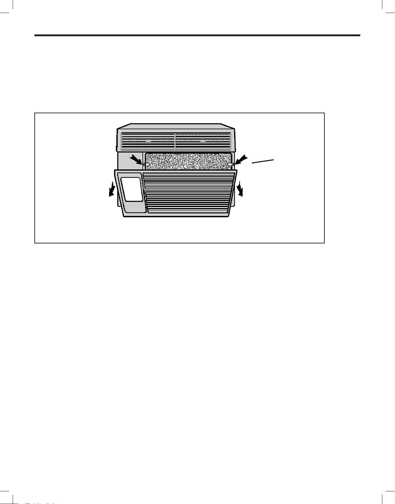
Figure 1
FILTER
RETAINER CLIPS
The filter can be removed for cleaning by opening the front of
the unit and releasing the filter from its retaining clips.
4

Hazardgard Special Features
WARNING
• Permanent Split-Capacitor, totally enclosed fan motor to
assure efcient operation even under adverse electrical
conditions.
• Motor has a special stainless steel shaft to resist corrosion
and a hermetically sealed overload for arc-free operation.
• High capacity compressor with internal hermetically sealed
overload.
• Contains transient voltage suppressor to protect controls
against transient voltage spikes. Provides solid state switches
for arc- free operation.
• Hot gas bypass low ambient control to permit operation without
freezing at outdoor ambient temperatures as low as 45°F (7°C).
• IP44 Environmentally sealed electrical components protect
against ingress of moisture ( ATEX & IECEx )
• Polyester powder nish, oven-baked for an attractive, long-
lasting nish
Friedrich Air Conditioning quality has been proven by more than 30 years of successful experience from the Gulf of Mexico
to the searing sands of the Arabian Desert.
• Copper tubing/aluminum hydrophilic coated n coils
• Galvanized steel cabinet and base pan, all bonderized.
• Slide-out chassis for easy installation in window or through–
the–wall.
• Extra insulation inside, including completely insulated plenum
chamber for quieter, more efcient cooling.
• Entire unit test run in environmental chamber before crating.
• Eight-way air ow control for uniform circulation
• Condensate drain with exclusive mosquito trap.
• 15amp or 20amp circuit with time-delay fuse required.
Accommodates direct wiring.
• Long lasting 3/8” (10mm) thick air lter, germicidally treated,
easily removed for cleaning
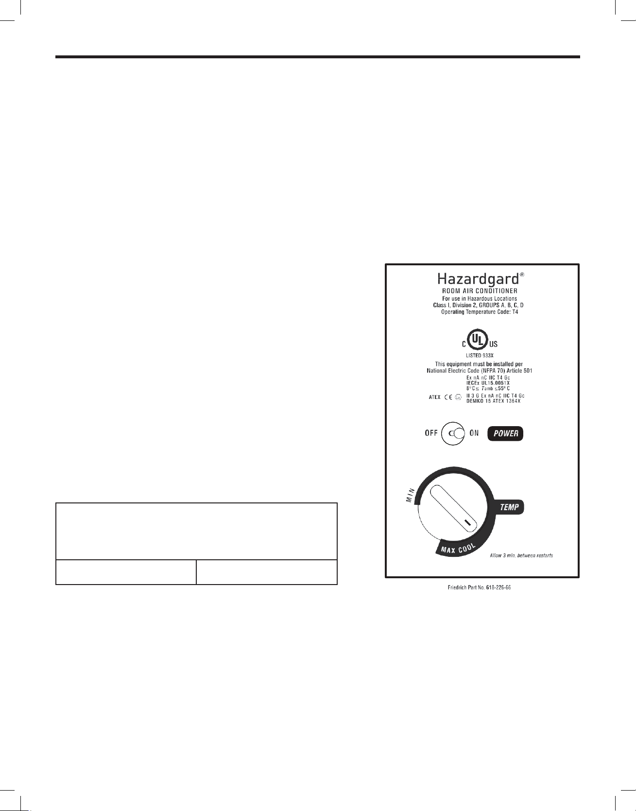
Control Panel
Function Control (Power)
This switch is a double pole, single throw toggle switch.
ON - Turns everything on.
OFF - Turns everything off.
POWER MUST BE DISCONNECTED AT
CIRCUIT BREAKER/FUSE BEFORE SERVICING!
Temperature Control
The knob at the bottom is the thermostat which is a cross ambient type
used to maintain the desired comfort level. The thermostat reacts only to
a change in temperature at the bulb location - turn the knob clockwise to
set cooler, counter- clockwise for warmer.
Friedrich leads with the rst UL Listed Room Air Conditioners designed
to cool living quarters and other enclosures situated in hazardous loca-
tions where specic volatile ammable liquids or gases are handled or
used with enclosed containers or systems.
Friedrich Hazardgard room air conditioners are designed to meet the
National Electrical Code, Article 500 requirements for Class I, Division
2, Groups A,B,C,D Hazardous locations, CERTIFIED BY UNDERWRITERS
LABORATORIES FOR USE IN CLASS 1, DIVISION 2, GROUPS A,B,C,D
HAZARDOUS LOCATIONS.
5
ATEX & ICEX Standards Specic to Models SH20N50AT & SH24N20AT
SH20N50AT and SH24N20AT Adhere to the following certications:
CERTIFIED PER STD. NO. ANSI/ISA 12.12.01,2013
PER STD. NO. IEC 60079-0, 6th Edition PER STD. NO. IEC 60079-15, 4th Edition
PER STD. NO. CAN/CSA C22.2 NO. 213-M1987
PER STD. NO. CENELEC EN 60079-0: 2012 + A11: 2013
PER STD. NO. CENELEC EN 60079-15: 2010
CERTIFICATION DEMKO 15 ATEX 1364X II 3 G Ex nA nC IIC T4 Gc
IECEX UL15.0051X DEMKO 15 ATEX 1364X
SH20N50AT & SH24N20AT
Specic Conditions of Use:
• Provision shall be made to prevent the rated voltage being exceeded by
the transient disturbances of more than 140% of the peak rated voltage..
• The equipment must be installed only for use in locations providing
adequate protection against the entry of solid foreign objects or water
capable of impairing safety.
• Only permanently wired cables may enter the cable glands. The user
shall provide for the required strain relief.
• Degree of protection will be safeguarded only when sealing and cable
entry ttings are properlytted. The Manufacturer’s instructions must
be followed.
• Cable Glands shall be mounted into the enclosurein such a way that they
are mechanically protected against impact force.
• To avoid the buildup of electrostatic charge, regularly clean the unit with
a damp cloth.
• The appliance is not to be used by persons (including children) with
reduced physical, sensory or mental capabilities, or lack of experience
and knowledge, unless they have been given supervision or instruction.
Children to be supervised not to play with the appliance.
The following additional previous editions of Standards noted under
the “Standards” section of this Certicate where applied to integral
Components as itemized below. There are no signicant safety related
changes between these previous editions and the editions noted
under the “Standards” section.
Junction Box, Part No. 25. 10 16
08, manufactured by Rose.
IEC 60079-7:200607, IEC 60079-31:
NOTICE: To maintain IP44 protection, the Hazardgard
unit must be installed in accordance to the installation
instructions stated in this document.
6

Installation Instructions
WARNING
Explosion Hazard
Electrical Shock Hazard
Electrically connect unit in accordance with NEC
Code Article 501. Failure to do so can result in
death, explosion, fire or electrical shock
Models SH15, SH20 and SH24
NOTE: THIS MANUAL INCLUDES INSTALLATION INSTRUCTIONS FOR BOTH WINDOW MOUNT
AND THROUGH- THE WALL INSTALLATIONS
Electrical Requirements
ALL FIELD WIRING MUST MEET THE REQUIREMENTS OF THE NATIONAL ELECTRICAL CODE (ANSI/NFPA
70) ARTICLE 501.
THE FIELD-PROVIDED CIRCUIT PROTECTION DEVICE (HACR CIRCUIT BREAKER OR TIME DELAY FUSE) MUST NOT EXCEED THE
AMPACITY INDICATED ON THE PRODUCT NAMEPLATE.
IMPORTANT: Before you begin the actual installation of your air conditioner, check local electrical codes and the information below.
Your power supply must be the same A.C. voltage and frequency (hertz) as marked on the name plate located on the chassis. Only
alternating current (A.C.), no direct current (D.C.), can be used.
An overloaded circuit will invariably cause malfunction or failure of the air conditioner; therefore, it is extremely important that the
electrical power is adequate. Consult your dealer or power company if in doubt.
The following instructions are for HAZARDGARD models and cabinet sizes listed below.
GROUPS CABINET SIZE (H x W X D)
SMALL CHASSIS SH15 15 15/16” x 25 15/16” x 27 3/8”
(405 mm x 660 mm x 695 mm)
MEDIUM CHASSIS SH20, SH 24 17 15/16” x 25 15/16” x 27 3/8”
(455 mm x 660 mm x 695 mm)
Model Number Plug Type Circuit Rating
Time Delay Fuse
SH15 Junction Box 250V-15 Amp
SH20, SH24 Junction Box 250V-15 Amp, 250V-20 Amp
7

Window Mount Installation Hardware
ITEM
No.
1 SUPPORT BRACKET 2
2 SCREW, 10 - 24 x 1” HEX HEAD 4
3 10 - 24 FLAT WELDNUT 4
4 SCREW, SHEET METAL #12A x 2” 7
WINGBOARD ANGLE MOUNTING
5 WINGBOARD ANGLE, TOP 1
6 WINGBOARD ANGLE, SIDE 2
7 SCREW, SHEET METAL #8A x 3/8” 2
WINGBOARD MOUNTING PARTS
8 WINGBOARD (MASONITE) 1
9 J TYPE SPEED NUT 4
10 WINGBOARD CLIP (SPRING STEEL) 4
11 SCREW. #8A x 1/2” PHILLIPS TRUSS HD. 4
12 WINDOW SEAL GASKET (DARK FOAM) 1
DESCRIPTION QTY.
SHELL MOUNTING PARTS
WINDOW SEALING
ITEM #5 SEE ACCESSORY DETAIL IMAGE
ITEM #6 SEE ACCESSORY DETAIL IMAGE
ITEM #12 SEE ACCESSORY DETAIL IMAGE
8
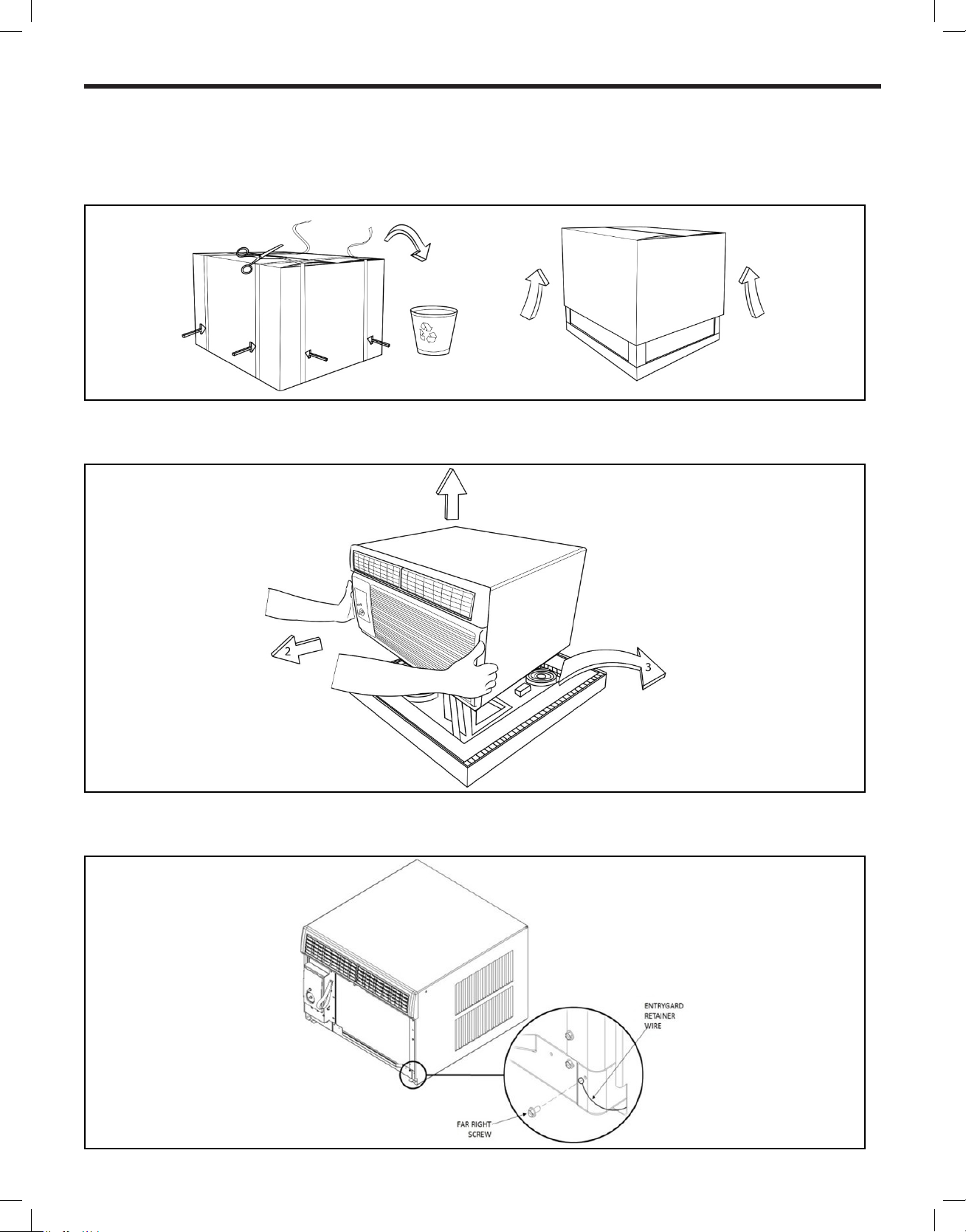
Unpacking The Unit
STEP 1 Cut the packing straps and remove box pulling it up, remove corner-post and protective packing, conserve the berboard
wing board in a safe place, it will be used later.
Figure 2
STEP 2 Remove decorative plastic return air grille to a safe area away from the unit.
STEP 3 Remove the installation hardware, two gaskets from beneath the unit, and place them in a safe area away from the unit.
Figure 3
STEP 4 Remove the chassis retainer by removing the far right screw in the basepan (see Figure 4); save this screw to reattach the
chassis retainer after installation.
Figure 4
9
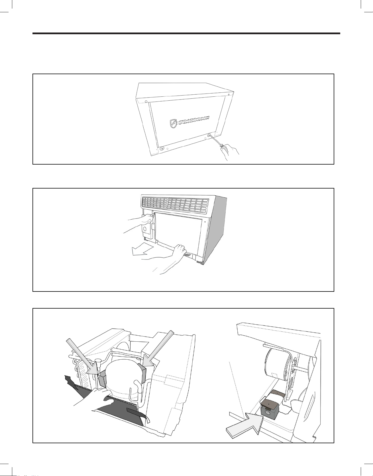
Unpacking The Unit
STEP 5 Remove and discard the two retainer screws and plastic bushings located at the rear of the unit. (Figure 5)
Figure 5
STEP 6 While an assistant holds the cabinet stationary, use the hand pull at the front of the base pan (see Figure 6) to pull the chassis
out of the cabinet.
Figure 6
STEP 7 Remove white foam blocks used to restrain the compressor during shipment. Also remove junction box from under fan motor.
Figure 7
10
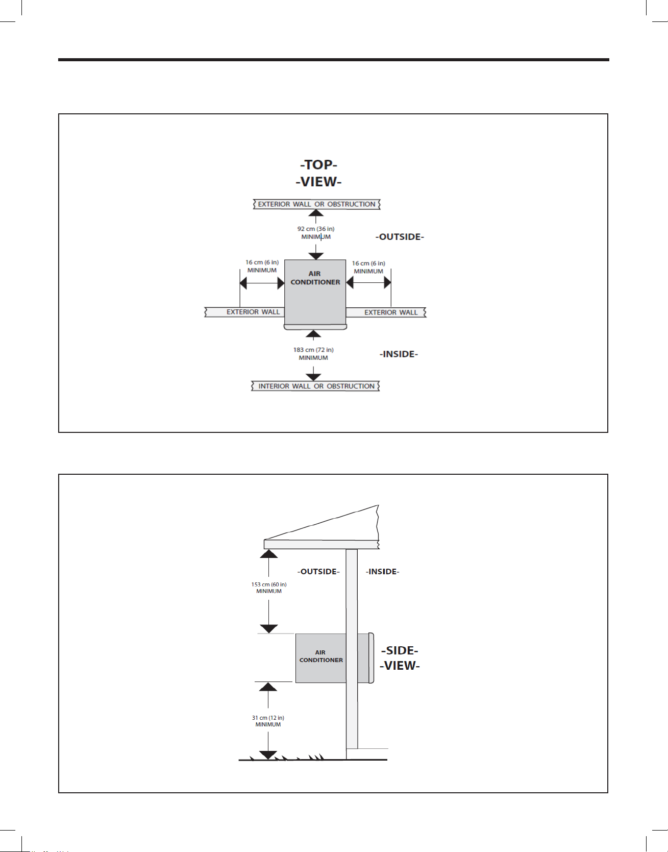
Installation: Outdoor/Indoor Clearances
Figure 8
Figure 9
11

Shell Installation: Through-the-wall Installations (as unit is shipped)
WARNING
Figure 10
EXTRA THICKWALL CONSTRUCTION
3.25" (82.55 MM)
MAXIMUM
LOUVERS
Top View
TOP VIEW SHOWING BEVELEDSIDES
FOR AIR
should
WALL BELOW
UNIT MUST ALSO BE BEVELED TO
ASSURE PROPER TILT ANGLE.
No louver should be
blocked. Maintain a
45 deg angle until
you clear the wall
CONDENSER AIR
INTAKE LOUVERS
Figure 11
HOLE SIZE REQUIREMENTS
NOTE: THESE DIMENSIONS ARE FOR FINISHED HOLE SIZE
Falling Object Hazard
Not following Installation Instructions
for mounting your air conditioner can
result in property damage, injury, or
death.
Wall Preparation
The maximum wall thickness permissible without special construction is determined by the model size to be installed. THE OUT- SIDE
CABINET CONDENSER AIR INTAKE LOUVERS MUST NOT BE BLOCKED BY EXTENDING INSIDE THE WALL
AREA. Observe the maximum wall thickness shown as dimension “A”in (Figure 10).
Special Instructions For Extra Thick Walls
For installation in walls exceeding the maximum thickness shown as dimension A, the following suggested construction may apply.
(See Figure 10).
WALL THICKNESS
CONDENSER
AIR INTAKE
INTAKE a 45 deg angle
be maintained.
STEP 1 CHECKING WIRING AND PLUMBING: Check all wiring and plumbing inside and outside the wall to be sure none will be broken
where the hole is to be cut.
STEP 2 HOLE CONSTRUCTION: Depending on the size of the unit to be installed, layout the hole dimensions in accordance with the
chart below (See Figure 11). Cut and frame in the hole to the nished dimensions. Use 2” x 4” material for framing and follow
the suggested typical installations in (Figure 12, 13 or 14 on Page 13.
NOTE: IF THE WALL CONSTRUCTION IS TYPICAL FRAME OR 2 X 4 STUDDING WITH BRICK OR STONE VENEERS, LOCATE THE HOLE
NEXT TO ONE OF THE STUDS. FOR MASONRY, CONCRETE OR CINDER BLOCK WALLS, LOCATE THE HOLE FOR CONVENIENCE.
FINISHED
DIMENSION
SH15
CHASSIS
SH20, SH24
CHASSIS
A 16-3/16” 18-3/16”
B 26-3/16” 26-3/16”
12
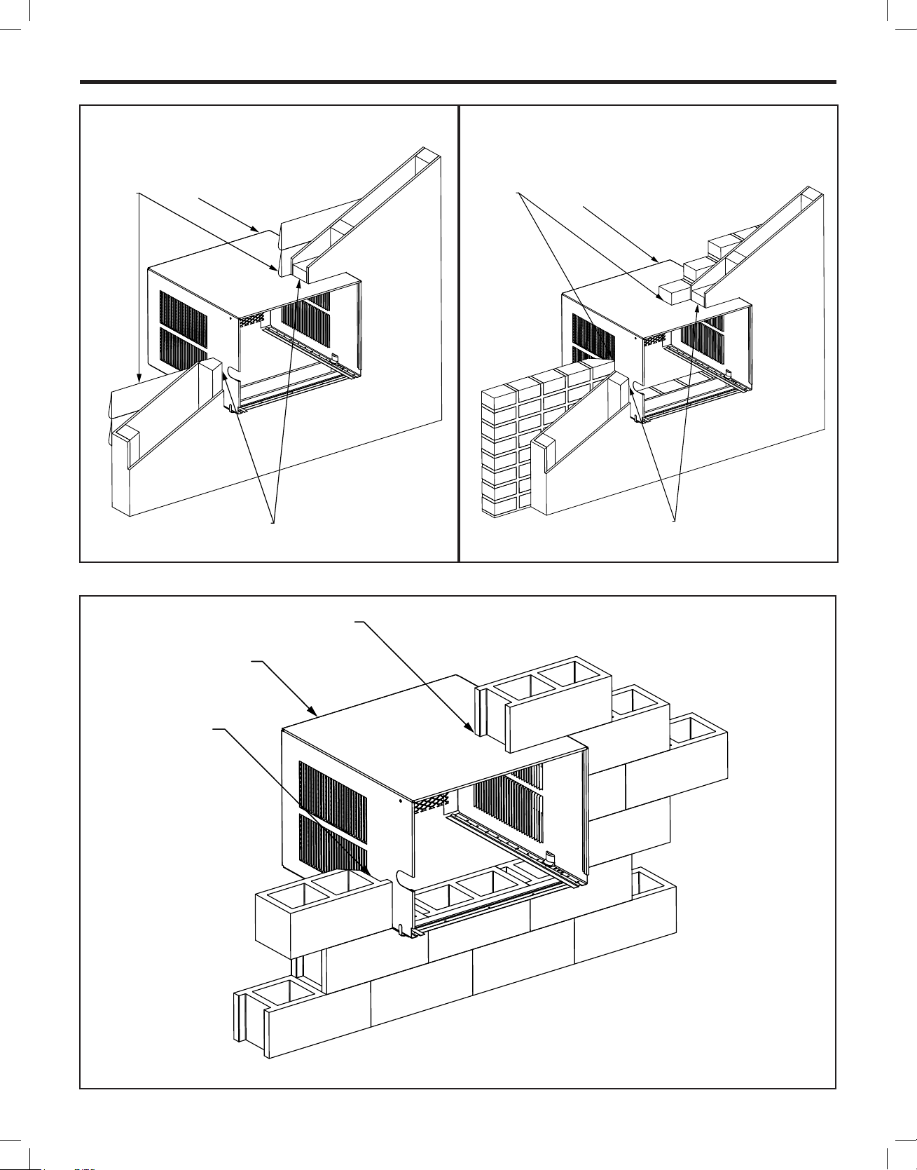
Figure 12 FRAME WALL CONSTRUCTION Figure 13 BRICK VENEER CONSTRUCTION
CAULK ALL
SIDES
INSIDE AND
OUTSIDE
CABINET
SHIM TO FILL IN VOID AT
THE TOP AND SIDES WITH
WOOD AS REQUIRED
CAULK ALL
SIDES INSIDE
AND OUTSIDE
CABINET
SHIM TO FILL IN VOID AT
THE TOP AND SIDES WITH
WOOD AS REQUIRED
Figure 14 SOLID MASONRY CONSTRUCTION
CAULK ALL
SIDES INSIDE
AND OUTSIDE
CABINET
MORTAR
13
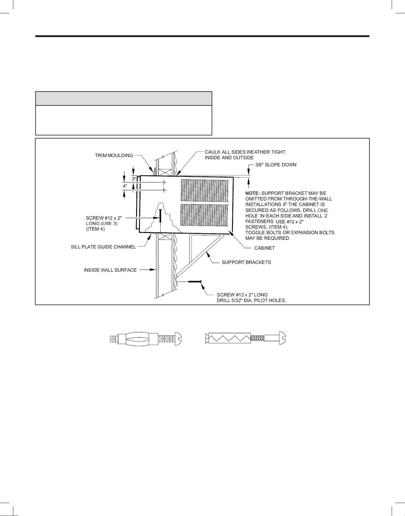
STEP 3 Slide the cabinet into the hole far enough to allow the guide-channel of the sill plate to contact the inside wall surface
(See Figure 15).
STEP 4 Drill three (3) 5/32” diameter pilot holes through holes in sill-plate into the framing and install three (3) #12 x 2” long screws
(Item #4) (See Figure15).
NOTICE
Instructions for mounting sleeve with slope must be observed to
prevent entry of water into room. Potential property damage can
occur if instructions are not followed.
Figure 15 TYPICAL INSTALLATION
NOTE: ALT E R N ATE FASTENERS WHICH MAY BE USED FOR SE CURING THE SIL L PL ATE IN THE WA L L, AN D THE SUPPORT BR ACK E TS
TO THE OUTSIDE WALL ARE NOT FURNISHED, BUT ARE AVAIL ABLE AT A LOCAL HARDWARE STORE.
MOLLY OR TOGGLE BOLT EXPANSION ANCHOR BOLT
STEP 5 Drill two (2) 5/32” (4 mm) dia. pilot holes in each side at the locations shown (Figure 15) and install four (4) #12 x 2” screws
(Item #4). If the hole construction in Step 2 provides a sturdy mount with solid vertical studs, no support brackets are
required. The installation must support the weight of the unit plus an additional weight of 400 pounds (185 kg) on the rear of
the cabinet. The support brackets may be used for through-the-wall installations as shown in (Figure 15), for additional support.
STEP 6 If desired, trim around the cabinet on the room side with a suitable frame molding furnished by the installer (See Figure 15).
STEP 7 Skip to chassis wiring and preparation on page 21 for Non ATEX or page 23 for ATEX and IECEx.
14
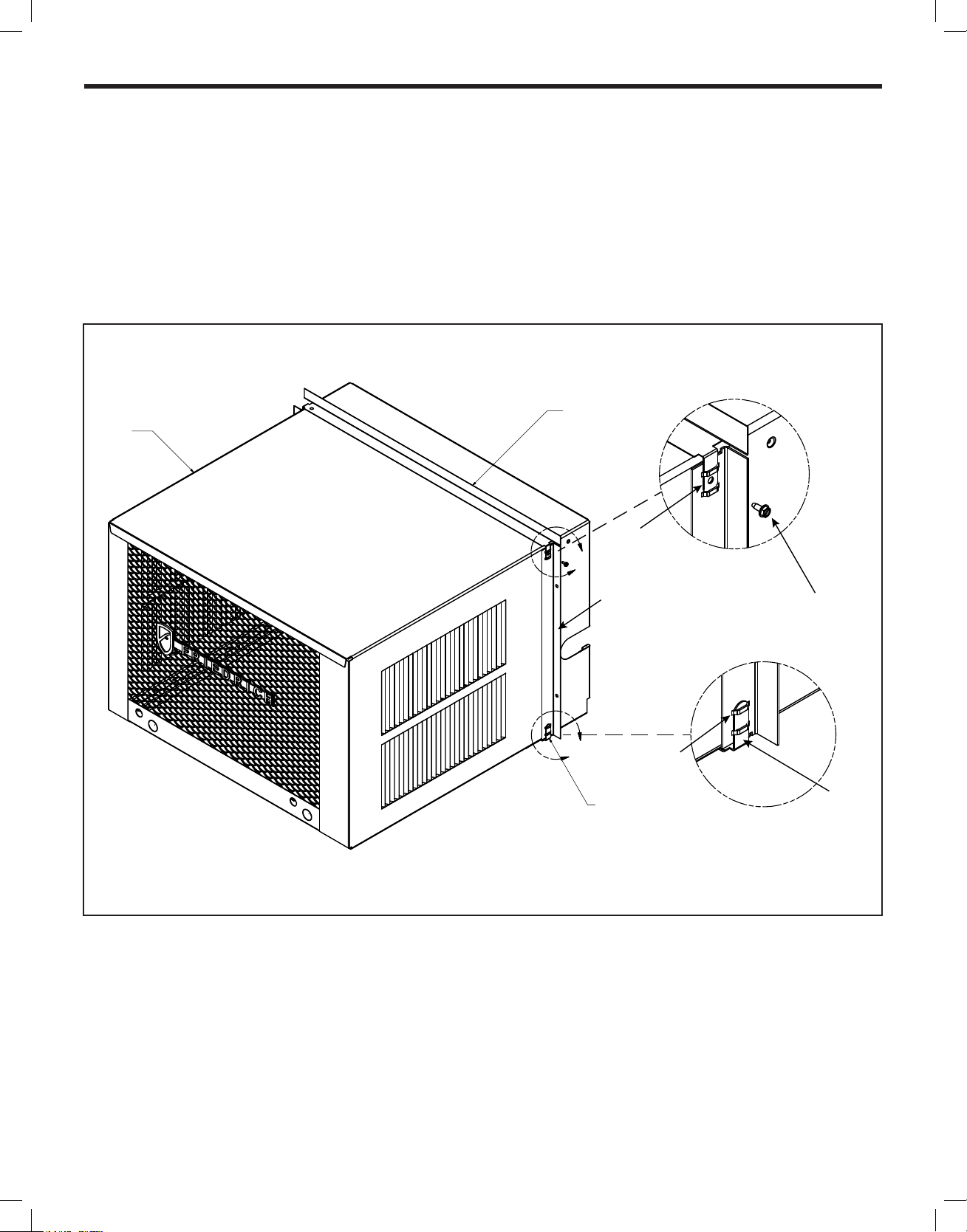
Shell (Cabinet) Preparation for Installation
STEP 1 Remove still plate and bend the taps up and reinstall. See (DETAIL 16-A).
STEP 2 Take the side angles (item #6) and engage its loops in the tabs (both sides) of the sill plate. (DETAIL 16-A).
STEP 3 Take the top Flange (item #5) and engage its tabs in the top loops of the side anges (DETAIL 16-B).
STEP 4 Install two (2) screws (Item #7) to secure the top angle tabs and the side angle in the side of the cabinet (Detail 16-B).
Figure 16
TOP ANGLE (ITEM #5)
CABNET
TAB
A
SIDE ANGLE (ITEM #6)
2 REQUIRED
B
SILL PLATE TAB
LOOP
D E T A IL 16 - B
8-A X 3/8" LONG SCREW
(ITEM #7) 2 REQUIRED
D E T A IL 1 6 - A
TAB
15
Shell Installation: Sash Window Installations
WARNING
Figure 18
3/8" (10 MM) DOWN SLOPE
10 - 24 X 1" HEX HEAD
SCREW (ITEM #2)
SUPPORT BRACKET
(ITEM 1)
A 1" X 4" OR 2" X 4" SPACER SHOULD BE USED BE-
ALUMINUM, ASBESTOS OR VINY LSIDING.
#12A X 2" SCREW
(ITEM#4)
SUPPORT BRACKET
(ITEM 1)
10 - 24 FLAT WELD
NUT (ITEM #3)
Falling Object Hazard
Not following Installation Instructions
for mounting your air conditioner can
result in property damage, injury, or
death.
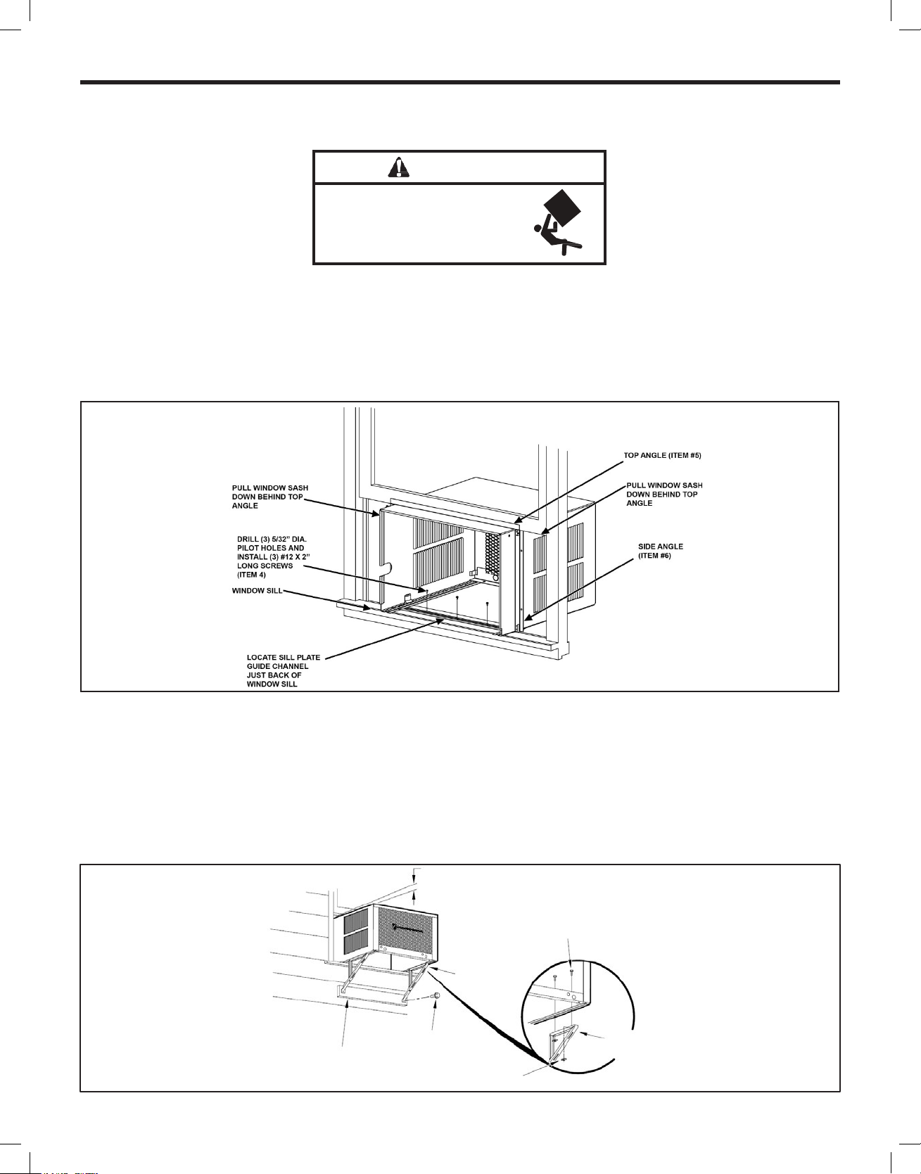
STEP 1 Check the window sill and frame to be sure they are in good condition and rmly anchored to the wall. Repair if necessar y.
STEP 2 CABIN E T MOUNTING: Ra i s e the lower window sash 1/4” more than th e height of the cabinet. Caref u l ly slide the cabi n et through
the open window until the sill plate channel rests behind the window sill and the top support angle (Item #5) rests against the
window (See Figure 17). Center the cabinet side to side and drill three (3) 5/32” diameter pilot holes into the window sill using
the holes in the cabinet sill plate as a guide. Install three (3) #12A x 2” long screws (Item #4) (See Figure 17).
Figure 17
STEP 3 OUTSIDE SUPPORT MOUNTING: Assemble the support brackets (Item #1) to the bottom rails of the cabinet with four (4) 10-24
1” long screws (Item #2) and four (4) 10–24 at nuts (Item #3). Adjust the support br ackets to bring the bottom pads in contac t
with the wall surface. (See Figure 18.)
A 1” x 4” or 2” x 4” SPACER SHOULD BE USED BETWEEN THE WALL AND THE SUPPORT BRACKETS WHEN
INSTALLED ON ALUMINUM OR VINYL SIDING). Drill 5/32” (4 mm) diameter pilot holes, and secure the brackets to the wall
with two (2) #12A x 2” long screws (Item #4). Adjust the support brackets to provide an approximate 3/8” (10 mm) down slope
towards the outside for drainage. Tighten all screws. (See Figure 18).
TWEEN THE WALL AND BRACKET WHEN INSTALLED ON
16
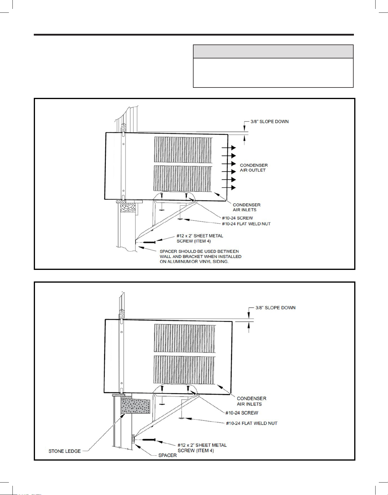
Typical Installation: Sill Plate
NOTICE
The illustrations below show a standard frame construction
installation as well as some suggested ways of adapting the
support bracket to thick walls and large brick ledges.
Figure 19
Instructions for mounting sleeve with slope must be observed
to prevent entry of water into room.
Failure to follow instructions can result in property damage.
Figure20
17
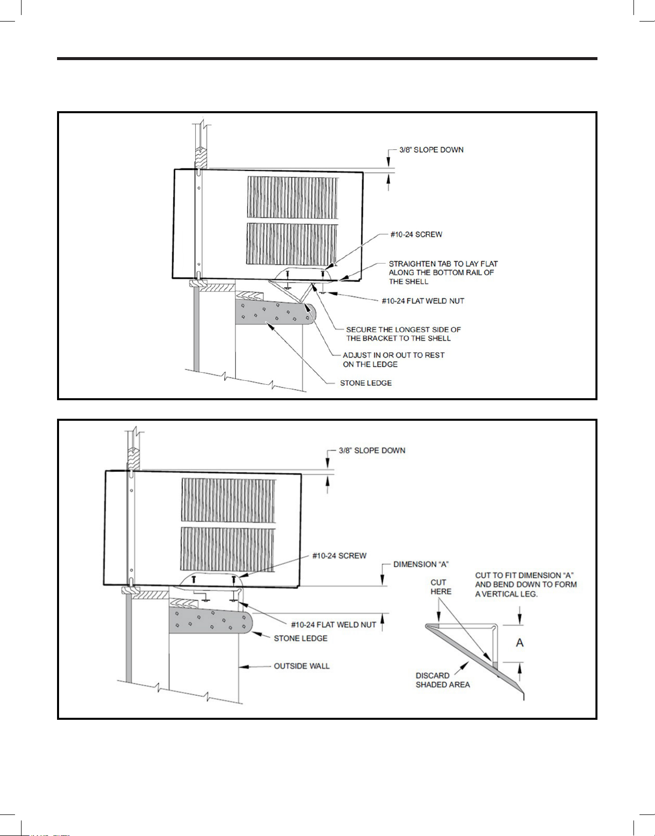
Typical Installation: Sill Plate (cont.)
Figure 21
Figure 22
18
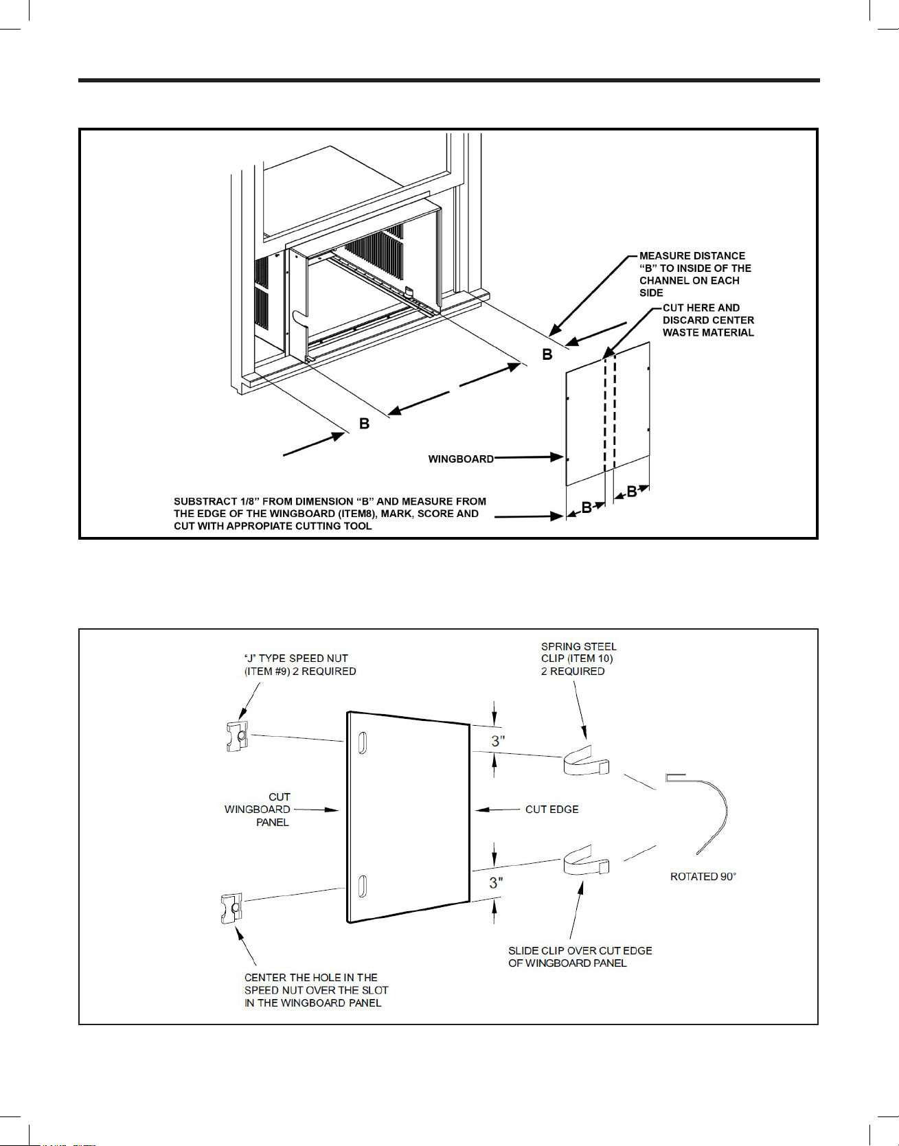
Figure 23
STEP 4 CUT WINGBOARD PANELS: Measure and cut the wingboard panels from the supplied masonite (Item #8) to t the spaces
between the side window channels and the sides of the cabinet (See Figure 23).
NOTE: AFTER CUTTING PANELS, MAKE A TRIAL TEST TO SEE IF THEY FIT THE SPACE WITH ABOUT 1/8” CLEARANCE BEFORE
GOING TO STEP 5.
Figure 24
STEP 5 ASSEMBLE CLIPS TO WINGBOARD PANELS: Assemble “J” type speed nuts (Item #9) and spring steel clips (Item #10) to the
edges of the cut wingboard panels (See Figure 24).
19
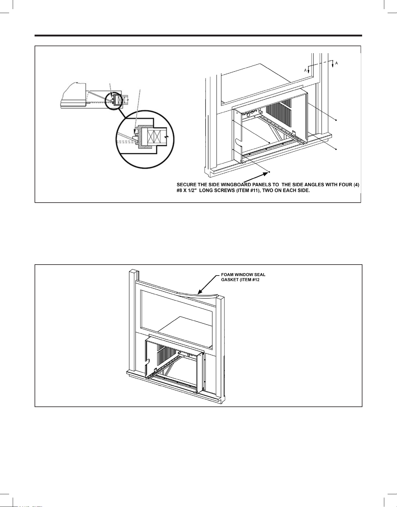
Figure 25
SECTION A -A
TOP OF CABINET
WINDOW JAM
CLIP (ITEM10)
PLACE WINGBOARD PANEL IN
WINDOW JAM TO COMPRESS
THE
RUNNERS,
PLACE
INDICATED BY THE DOTTED LINE.
SPRINGS INSIDE THE
AND SWING THE PANEL INTO
STEP 6 INSTALL SIDE WINGBOARD PANELS: Be sure that the cabinet has been secured to the window sill and the outside support
brackets have been installed as shown in (Figures 19 and 20) on Page 17. Raise the window sash and install the right and left
side wingboard panels (See Figure 25).
STEP 7 INSTALL WINDOW SEALING GASKETS: Measure and cut the dark foam window seal gasket (Item#12) and install it between
the upper glass panel and the top part of the lower sash (Figure 26).
Figure 26
NOTE FOR REASONS OF SECURITY , THE CUSTOMER MUST PROVIDE A MEANS OF PREVENTING THE WINDOW FROM OPENING.
STEP 8 When possible, caulk the outside of the installation with industrial type caulking to prevent air and water leaks.
STEP 9 Skip to chassis wiring and preparation on page 21 for Non ATEX or page 23 for ATEX and IECEx.
20
Chassis Wiring and Preparation (Non ATEX)
1 SHEET METAL SCREW
Figure 27
PROVIDED HARDWARE
1 JUNCTION BOX
2 MOUNTING LEGS
2 LEG SCREWS
2 HOLE COVERS
1 STAINLESS STEEL
GROUND SCREW
2 SCREWS
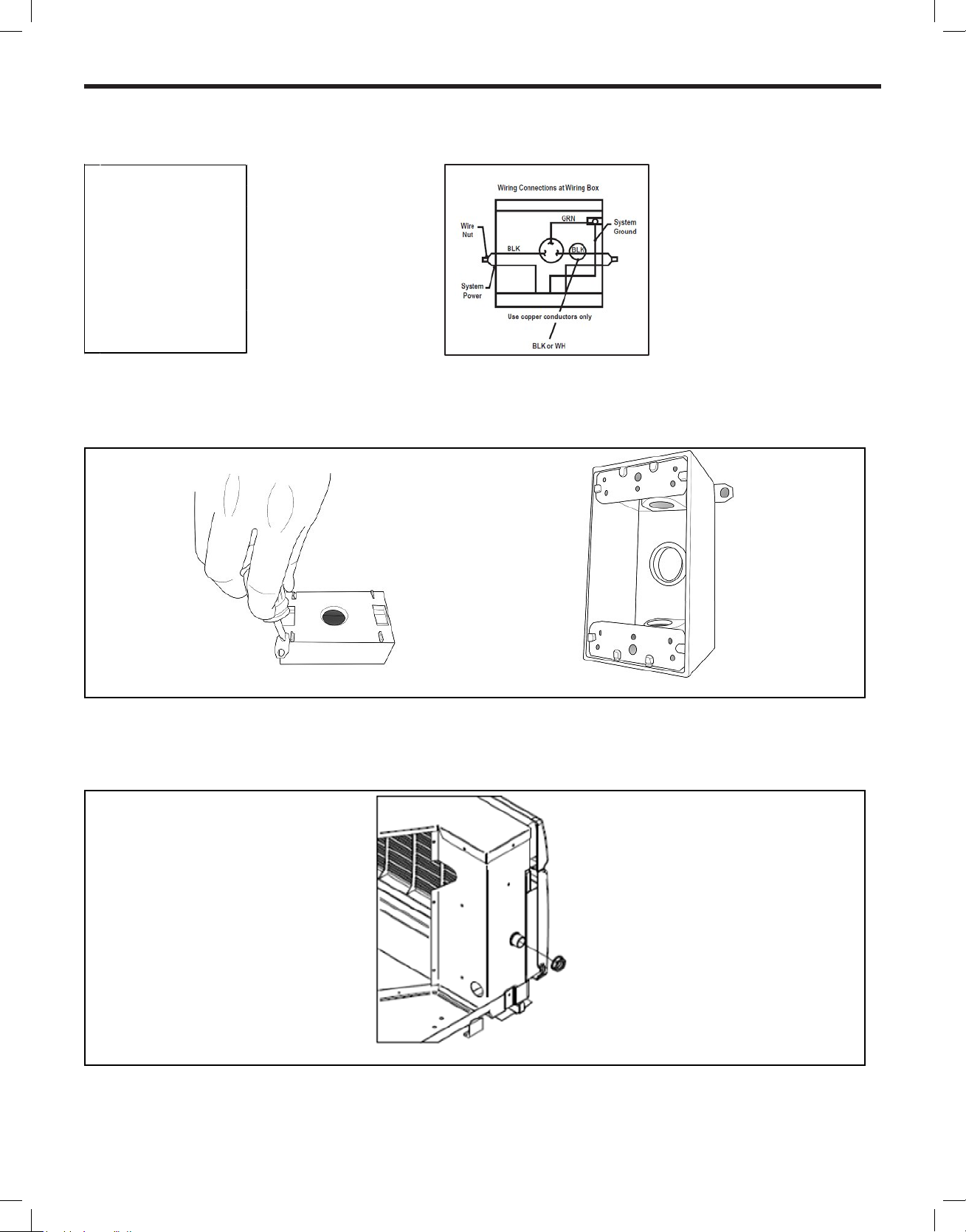
STEP1 Remove the junction box, cover and screws from the shipping position underneath the fan motor (See Figure 7). Install one
junction box mounting leg in the upper left position facing the rear of the junction box. (Figure 27)
STEP2 Remove and discard the threaded bushing wire protector from the conduit connector on the side panel of the control
compartment. Install eld supplied cable gland as required. Strip the wires approximately 1/2 inch (13 mm).
Figure 28
21
Chassis Wiring and Preparation
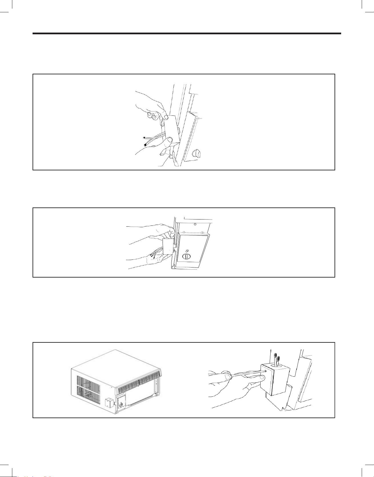
STEP 3 Insert all wires into the rear of the junction box and thread the box onto the threaded bushing until tight.
Figure 29
STEP 4 Back off clockwise until the junction box is vertical with the mounting leg at the upper–right position facing the box opening.
Be sure that the shell can slide between this box and the chassis.
Figure 30
STEP 5 Insert the unit in the shell see Page 25 for help, be sure that the shell can slide between junction box and the chassis.
NOTE: Field wiring conductors to be copper and a minimum of 12 AWG. Complete junction box wiring and cover to prevent
ingress from dust and moisture. All wiring connections to the junction box are to be made with cable glands.
Figure 31
22
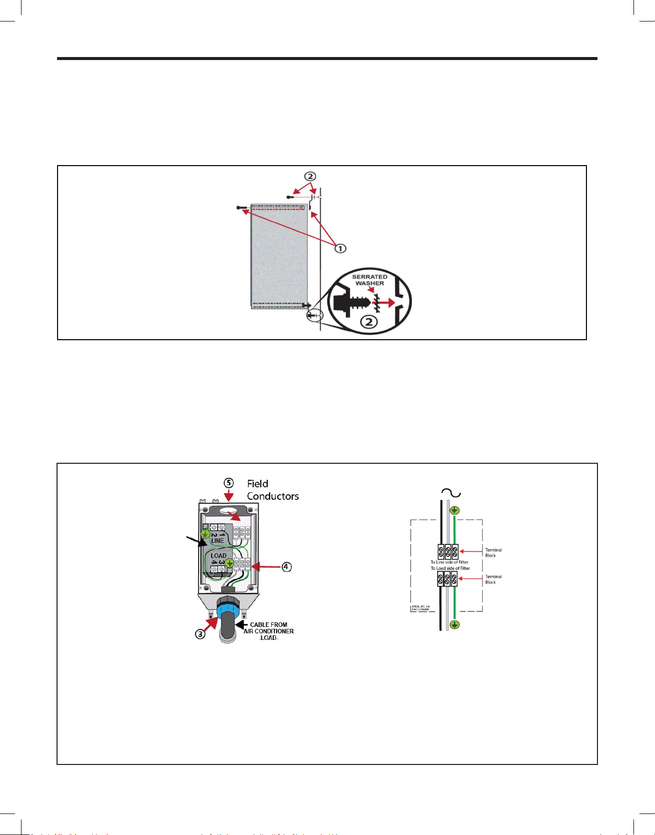
Figure 33
-FIELD CONNECTION-
EMI Filter
-AIR CONDITIONER-
Chassis Wiring and Preparation (ATEX & IECEx Models)
STEP1 Remove the junction box from the shipping position underneath the fan motor (Figure 7). Install junction box mounting legs
to back of the junction box using 4 provided machine screws (Figure 32-1). Mount junction box to provided holes on side of air
conditioner sleeve using 4 provided sheet metal screws and 4 serrated washers. Ensure serrated washers are between legs of
junction box and painted metal sleeve (gure 32-2).
Figure 32
STEP 2 Proceed to make the STEP 1 of the Chassis Installation (see page 25 ) then come back to STEP 3
STEP 3 Insert air conditioner’s electric cable through provided cable gland on bottom of electrical junction box and tighten cable gland
nut (see Item 3) torque to 15 N-m, 106 in-lbs. Strip the three electrical conductors approximately 6.35 mm (1/4 inch) install
under provided terminal block LINE terminals and tighten (Item 4). Fixed eld wiring must include a eld provided disconnect
(all poles). Provide xed eld wiring conductors and cable gland with a minimum IP44 rating. Connect wiring conductors under
provided terminal block LOAD terminals and tighten (Item 5). Field conductors to be copper and a minimum 1.29 to 2.06 mm
(16 to 12 AWG). Ensure both LINE, LOAD and GROUNDs are adequately secured to provided termination points.
NOTE:
NOTE:
NOTE:
Terminal block screw tightening torque .56N-m (5 in lbs) max. Wire size should be 1.29 to 2.06 mm (12 to
16AWG)
Notice: this air conditioner must be installed in accordance with national wiring regulations of country where
installed. Electrical connections to equipment must be carried out by qualified personnel per EN/IEC 6079-14.
Fixed wiring must include a field provided disconnect (all poles.) Repairs affecting hazard location protection
must be carried out by a qualified electrician in accordance with NEC/CEC 501.10 (B) and EN/IEC 60079-19.
To maintain IP44 protection and electrical safety, the Hazardgard unit must be installed in accordance to the
installation instructions provided with this product.
23
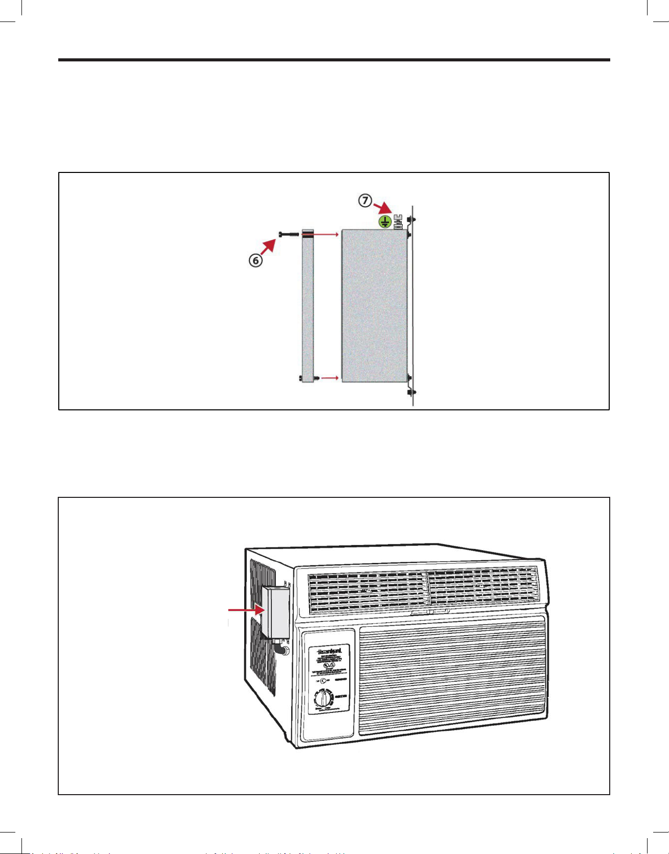
Chassis Wiring and Preparation (ATEX & IECEx Models)
Figure 34
EXTERNAL GROUND
-See Note-
STEP 4 Complete junction box wiring, cover and tighten cover screws (Figure 34-6) to prevent ingress from dust and moisture.
NOTE: Per EN/IEC 60079-0, external grounding or earthing may be necessary.
If required, use provided external ground clamp which can accept two cables of up to 6mm (Figure34-7).
NOTE: This air conditioner shall be installed in accordance with national wiring regulations of the country where installed.
Electrical connections to equipment must only be carried out by qualied personnel per NEC/CEC 501.10 (B) EN/IEC 60079-14.
Repairs affecting hazard location protection must be carried out by a qualied electrician in accordance with NEC/CEC 501.10
(B) EN/IEC 60079-19.
Figure 35
INSTALLATION
ELECTRICAL JUNCTION
BOX
WITH EMI FILTER
24

Chassis Installation
CAUTION
CAUTION
WARNING
Explosion Hazard
Electrical Shock Hazard
Electrically connect unit in accordance with NEC
Code Article 501. Failure to do so can result in
death, explosion, fire, or electrical shock.
STEP1 Slide the chassis into the cabinet stopping approximately 3” from full insertion. Stuff the chassis seal gasket (Item
#12) one inch deep between the chassis and the cabinet (Figure 36). Begin at either bottom corner and go up the side, across
the top, and down the opposite side. Make sure that the gasket is behind the conduit connector (furthest from you). Push the
chassis into the shell the remaining distance so that the plastic front shrouds the front edge of the shell. Fasten the junction
box mounting foot to the shell with the sheet metal screw.
If chassis seal gasket is not installed, the operation of the unit will be negatively affected. Also, the operation noise and outside
noise will be amplied.
Excessive Weight Hazard
Usetwo or more people when
installing your air conditioner.
Failure to do socan result in
backor other injury.
Cut/Sever
Although great care has been
taken to minimize sharp edges
in the construction of your unit,
use gloves or other hand
protection when handling unit.
Failure to do socan result in minor
to moderate personal injury.
NOTE: Field wiring must be provided to this junction box in accordance with NATIONAL ELECTRIC CODE (NFPA 70, 2008 or current
edition) ARTICLE 501. Field and equipment grounds are to be terminated at the post in the junction box with the green screw
provided. Equipment power leads are to be connected with the eld supply by means of wire nuts (not provided). Install the
gasket and cover plate onto the junction box.
Figure 36
CHASSIS SEAL GASKET
25
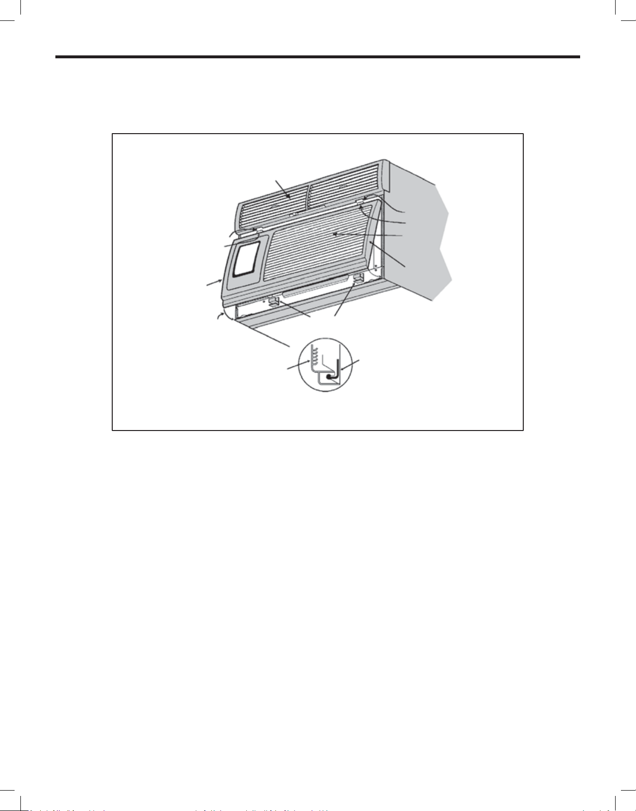
Figure 37
Discharge Air Plenum
Slot
Tab
DETAIL 2
Return Air Grille
DETAIL 1
DETAIL 1
DETAIL 3
Latches
Latch
Return air grille
DETAIL 4
(Cutaway)
STEP 2 Be sure that the lter is in place then install the return air grille (Figure 37). The top of the return air grille can be butted
against the bottom of the discharge plenum. Snap the grille into place by pushing the grille up and onto the unit’s latches at
the bottom. (See Detail 37-4).
Slot
Tab
Side view
STEP 3 You have completed your installation. Conduct a review of your installation to insure that the unit is safely and
securely installed.
End of Life
Customers are advised to ensure that the unit is disposed of in accordance with federal, state and local guidelines of their country.
Contact your municipal department of public works to inquire about the procedures for collecting and disposing of refrigerated appliances / air conditioners in your neighborhood.
26

Maintenance Checklist
Won’t Cool
If the unit operates, but doesn’t cool, check to see that the controls are properly set. Inspect the lter and if needed, clean it thoroughly.
Check to see if the chassis seal gasket is installed (refer to installation instructions).
Won’t Run
If the unit does not operate at all, check that the power supply connections are present and tight. Check for blown fuses or tripped circuit breakers. Replace blown fuses with the proper size time-delay fuse. The nameplate on the unit shows the proper fuse size. After
restoring power, wait three minutes before restarting the unit.
Inside Coil Freezes Up
Your Friedrich Hazardgard is designed not to freeze with outdoor temperatures as low as 45°F (7°C). Freezing should only occur when
the outside air is damp and below 45°F (7°C). If the indoor coil should ice over while cooling, set the thermostat to the warmest position
until the ice is gone. Setting the thermostat to a slightly warmer position will probably keep ice from forming on the coil. A dirty lter
will contribute to coil icing.
Cleaning
The front grille of your Friedrich, as well as the complete cabinet may be cleaned with warm water and a mild detergent. The coils and
base pan should be cleaned periodically for the most efcient operation. We suggest you call your Friedrich dealer for this service.
Lubrication
Fan motors are factory lubricated and sealed. No lubrication is required.
27
 Loading...