


Friedrich VHA24K25, VHA24K34, VHA24K50, VHA24K75, VEA24K25 Installation and Operation Manual
...INSTALLATION &
OPERATION GUIDE
VERT-I-PAK® A-SERIES
SINGLEPACKAGE
VERTICALAIR
CONDITIONINGSYSTEM
24,000BTU/h
920-159-04 (05-08)
920-159-04 |
|
|
|
Table of Contents |
|
Your Safety and the safety of others ............................................................................................................................... |
3 |
Installation Recommendations .................................................................................................................................... |
4 |
General Specifications |
|
Model Number Identification Guide ................................................................................................................................. |
5 |
VERT-I-PAK Chassis Specifications................................................................................................................................ |
5 |
Electrical Data .............................................................................................................................................................. |
5-6 |
Installation |
|
Utility Closet Dimensions................................................................................................................................................. |
7 |
Wall Plenum & Architectural Louver Installation .............................................................................................................. |
8 |
Drain Pan Installation ...................................................................................................................................................... |
9 |
Condensate Disposal System ......................................................................................................................................... |
9 |
Indoor Return Air Grille Installation.................................................................................................................................. |
9 |
Indoor Airflow Data ........................................................................................................................................................ |
10 |
Chassis Installation ....................................................................................................................................................... |
10 |
Remote Thermostat Operation |
|
Remote Thermostat....................................................................................................................................................... |
11 |
Thermostat Connections ............................................................................................................................................... |
11 |
Desk Control Terminals ................................................................................................................................................. |
11 |
Auxiliary Fan Control ..................................................................................................................................................... |
11 |
Electrical and Thermostat Wiring Diagrams .................................................................................................................. |
12 |
Chassis Final Connection |
|
Final Installation checklist.............................................................................................................................................. |
13 |
Chassis Operation |
|
Fresh Air Door ............................................................................................................................................................... |
13 |
Low Ambient Protection................................................................................................................................................. |
13 |
Room Freeze Protection ............................................................................................................................................... |
13 |
Emergency Heat Override............................................................................................................................................. |
13 |
Emergency Heat Operation........................................................................................................................................... |
13 |
Service |
|
Servicing/Chassis Quick Changeouts ........................................................................................................................... |
14 |
Routine Maintenance .................................................................................................................................................... |
14 |
Error Codes ................................................................................................................................................................... |
15 |
Factory Dipswitch Configuration.................................................................................................................................... |
15 |
Accessories ................................................................................................................................................................... |
16 |
Warranty ....................................................................................................................................................................... |
17 |
2

920-59-04
Your safety and the safety of others are very important.
We have provided many important safety messages in this manual and on your appliance. Always read and obey all safety messages.
This is a safety Alert symbol.
This symbol alerts you to potential hazards that can kill or hurt you and others. All safety messages will follow the safety alert symbol with the word “WARNING” or “CAUTION”. These words mean:
WARNING
CAUTION
You can be killed or seriously injured if you do not follow instructions.
You can receive minor or moderate injury if you do not follow instructions.
All safety messages will tell you what the potential hazard is, tell you how to reduce the chance of injury, and tell you what will happen if the instructions are not followed.
NOTICE |
A message to alert you of potential property damage will have the word “NOTICE”. |
Potential property damage can occur if instructions are not followed. |
Read this manual thoroughly prior to equipment installation or operation. It is the installer’s responsibility to properly apply and install the equipment. Installation must be in conformance with the NFPA 70-2002 National Electric Code current edition, Universal Mechanical Code current edition and applicable local or national codes.
Proper installation is not difficult, but it is essential.
3
920-159-04
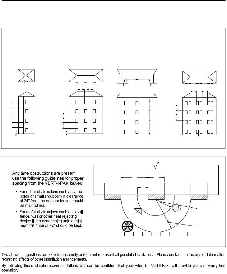
Vert-I-PakInstallationRecommendations
Forproperunitperformanceandmaximumoperatinglifepleaserefertotheminimuminstallationclearancesbelow.
Figure1
VERT-I-PAK® units must be installed on an outside wall. Confined spaces and/or covered areas should be avoided. Units should be installed no closer than 12" apart when two units are side by side. If three or more units are to operate next to one another allow a minimum of 60" between units or pairs of units. Also, a vertical clearance of 60" should be maintained between units. Units installed on the bottom floor should be mounted at least 6" off of the ground.
6" |
|
B |
|
|
60" 60" |
A |
|
|
|
SMALL RECESS OK |
LARGER RECESS OK. IF A> 5xB |
60" |
60" |
|
|
|
60" |
|
|
60" |
|
|
|
|
|
|
60" |
60" |
|
60" |
|
|
|
|
|
|
60" |
60" |
|
|
|
6" |
6" |
|
|
12" |
|
|
|
|
|
Figure2 |
|
|
|
|
|
|
|
BUILDING |
|
|
|
60" |
24" |
|
|
VPAK |
12" |
VPAK |
VPAK |
|
|
|
|
24" |
|
|
POLE |
SHRUB |
|
|
- |
|
|
|
|
|
|
|
|
|
OUTDOOR |
|
|
72" |
|
CONDENSING |
|
|
|
|
UNIT |
|
|
FENCE |
|
|
MAJOR OBSTRUCTION |
||
|
|
|
||
|
|
|
® |
|
4 |
|
|
|
|

|
|
920-159-04 |
|
|
|
||
Vert-I-Pak® |
|
|
|
|
|
|
|
MODEL NUMBER |
V |
E |
A |
09 |
K |
34 RT H |
|
SERIES |
|
|
|
|
|
|
ENGINEERING CODE |
|
|
|
|
|
|
|
OPTIONS |
DESIGN SERIES |
|
|
|
|
|
ELECTRIC HEATER SIZE |
|
|
|
|
|
|
25 = |
2.5 KW |
|
|
|
|
|
|
|
||
NOMINAL CAPACITY |
|
|
|
|
|
34 = |
3.4 KW |
|
|
|
|
|
50 = |
5.0 KW* |
|
|
|
|
|
|
|
||
|
|
|
|
|
|
75 = |
7.5 KW** |
VOLTAGE |
|
|
|
|
|
** 24000 BTU only. |
|
|
|
|
|
|
|
||
Vert-I-Pak® |
|
|
|
|
|
|
|
|
R-22 |
|
|
|
|
|
|
|
23.125 |
|
|
|
|
|
|
|
23.125 |
|
|
|
|
|
|
|
47.25 |
|
|
|
|
|
|
Electrical Data
|
MODEL |
|
|
VHA/VEA24K25 |
VHA/VEA24K34 |
VHA/VEA24K50 |
VHA/VEA24K75 |
68 |
68 |
68 |
68 |
5

920-159-04
Electrical Requirements
Wire Size |
ONLY |
 ONLY
ONLY
Unit MUST
All 208/230v chassis must be hard wired with properly sized breaker. See namplate for specific chassis electrical requirements. See figure 9 (Page 12) for unit wiring and wall thermostat wiring. See Electrical Rating Table below for wire size. Use HACR type breakers to avoid nuisance trips. All field wiring must be done in accordance with NEC and local codes.
ElectricalRatingTables
|
|
|
|
15A |
14 |
20A |
12 |
30A |
10 |
SampleNameplate
SAMPLE
|
WARNING |
|
Electrical Shock Hazard |
|
Turn OFF electric power before service or installation. |
|
Unit must be properly grounded. |
|
Unit must have correct fuse or circuit breaker protection. |
|
Unit’s supply circuit must have the correct wire conductor size. |
|
All electrical connections and wiring must be installed by a qualified |
|
electrician and conform to the National Electrical Code and all local |
|
codes which have jurisdiction. |
6 |
Failure to do so can result in property damage, personal injury and/or death. |
|
|
|
|
 Loading...