


Uni - Fit R
Thru-the-Wall Series
Service and Parts
Manual
Thru-the-Wall Series
230 Volts  UE10C33 UE12C33
115 Volts UE08C13
Unifit Heat Cool Svc Parts 2010 (05/10)
Unifit. Cool (03/07)

Air Conditioner Service Manual |
|
TABLE OF CONTENTS |
|
Safety Precautions .......................................................................................................................................... |
|
|
3 |
Operating Instructions .................................................................................................................................. |
7 |
Controls.................................................................................................................................................... |
7 |
Remote control......................................................................................................................................... |
8 |
Disassembly instructions ............................................................................................................................. |
9 |
Mechanical Parts...................................................................................................................................... |
9 |
Air Handling Parts ................................................................................................................................... |
10 |
Electrical Parts ........................................................................................................................................ |
11 |
Refrigeration Cycle.................................................................................................................................. |
13 |
Schematic Diagram........................................................................................................................................ |
16 |
Wiring Diagram........................................................................................................................................ |
16 |
Troubleshooting Guide ................................................................................................................................ |
17 |
Piping System ......................................................................................................................................... |
17 |
Troubleshooting Guide ............................................................................................................................ |
18 |
Room Air Conditioner Voltage Limits....................................................................................................... |
21 |
Product specifications.................................................................................................................................... |
23~25 |
Exploded Vi ew ............................................................................................................................................. |
26 |
Replacement Parts List ............................................................................................................................... |
27~29 |
2 Room Air Conditioner

Safety Precautions
Safety Precautions
To prevent injury to the user or other people and property damage, the following instructions must be followed.
■Incorrect operation due to ignoring instruction will cause harm or damage. The seriousness is classified by the following indications.
 WARNING This symbol indicates the possibility of death or serious injury.
 CAUTION This symbol indicates the possibility of injury or damage to property only.
■ Meanings of symbols used in this manual are as shown below.
Be sure not to do.
Be sure to follow the instruction.
 WARNING
■ Installation
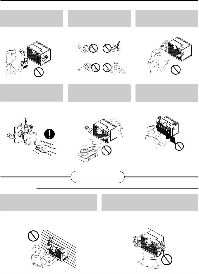
Don’t use a power cord, a plug or a loose socket which is damaged.
•Otherwise, it may cause a fire or electrical shock.
Do not disassemble or modify products.
•It may cause failure and electric shock.
Always plug into a grounded |
Do not modify or extend the |
outlet. |
power cord length. |
• Otherwise, it may cause a fire or |
• It will cause electric shock or fire |
electrical shock. |
due to heat generation. |
Be caution when unpacking and |
Do not use the power cord near flam- |
installing. |
mable gas or combustibles such as |
|
gasoline, benzene, thinner, etc. |
• Sharp edges may cause injury. |
• It may cause explosion or fire. |
Gasolin
Service Manual 3

Safety Precautions
■ Operation
Do not place heavy object on the power cord and take care so that the cord should not be pressed.
•There is danger of fire or electric shock.
Do not place the power cord near a heater.
•It may cause fire and electric shock.
Do not share the outlet with other appliances.
•It will cause electric shock or fire due to heat generation.
Do not allow water to run into electric parts.
•It will cause failure of machine or electric shock.
Take the power plug out if necessary, holding the head of the plug and do not touch it with wet hands.
•Otherwise, it may cause a fire or electrical shock.
Use a soft cloth to clean. Do not use wax, thinner, or a strong detergent.
•The appearance of the air conditioner may deteriorate, change color, or develop surface flaws.
Unplug the unit if strange sounds, odors, or smoke come from it.
•Otherwise it may cause fire and electric shock accident.
Ventilate the room well when using this appliance together with a stove, etc.
• An oxygen shortage may occur.
Do not open the suction inlet grill of the product during operation.
•Otherwise, it may electrical shock and failure.
Turn off the power and breaker firstly when cleansing the unit.
•Since the fan rotates at high speed during operation, it may cause injury.
Wax |
Thinner |
|
If water enters the product, turn off the the power switch of the main body of appliance. Contact service center after taking the power-plug out from the socket.
Turn off the main power switch when not using it for a long time.
•Prevent accidental startup and the possibility of injury.
4 Room Air Conditioner
Safety Precautions
Do not operate or stop the unit by inserting or pulling out the power plug.
•It will cause electric shock or fire due to heat generation.
Hold the plug by the head when taking it out.
•It may cause electric shock and damage.
Do not damage or use an unspecified power cord.
• It will cause electric shock or fire.
When gas leaks, open the window for ventilation before operating the unit.
•Otherwise, it may cause explosion, and a fire.
Do not operate with wet hands or in damp environment.
• It will cause electric shock.
Never touch the metal parts of the unit when removing the filter.
•They are sharp and may cause injury.
 CAUTION
■ Installation
Install the product so that the noise or hot wind from the outdoor unit may not cause any damage to the neighbors.
• Otherwise, it may cause dispute with the neighbors.
Keep level parallel in installing the product.
• Otherwise, it may cause vibration or water leakage.
Service Manual 5
Safety Precautions
■ Operation
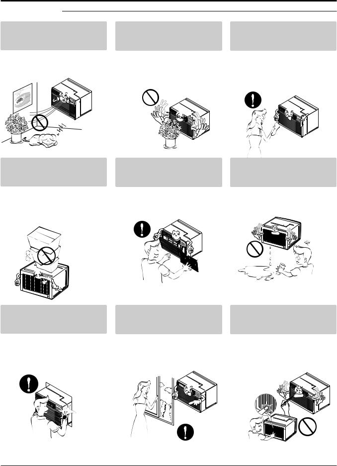
Do not put a pet or house plant where it will be exposed to direct air flow.
• It may cause injury.
Do not step on the indoor/outdoor unit and do not put anything on it.
•It may cause an injury through dropping of the unit or falling down.
Be cautious not to touch the sharp edges when installing.
• It may cause injury.
Do not block the inlet or outlet of air flow.
• It may cause product failure.
Always insert the filter securely. Clean it every two weeks.
•Operation without filters will cause failure.
Avoid excessive cooling and perform ventilation sometimes.
•Otherwise, it may do harm to your health.
Use a soft cloth to clean. Do not use wax, thinner, or a strong detergent.
•The appearance of the air conditioner may deteriorate, change color, or develop surface flaws.
Do not drink water drained from air conditioner.
•It contains containments and will make you sick.
Do not insert the hands or bars through the air inlet or outlet during operation.
•Otherwise, it may cause personal injury.
6 Room Air Conditioner
Operating Instructions
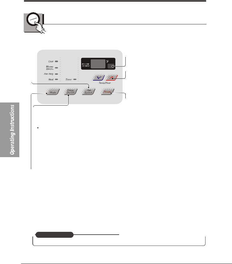
Controls
 FAN SPEED
 Every time you push this button,it advances the setting as follows:{High[F2]
 Low[F1]}
 High[F2]
 TIMER
TIMER
 SHUT-OFF TIME
 You will usually use shut-off time while you sleep.
 REMOTE CONTROL SIGNAL
RECEIVER
 TEMPERATURE SETTING
 Use this button to automatically control the temperature of the room
The tmeperature can be set within a range of
60 F to 86 F by increments of 1 F.
 The setting appears in the display.
 POWER
POWER
 To turn the air conditioner ON,push this button. To turn the air conditioner OFF,push the button again.
 This button takes priority over any other button.
 If unit is running,use Timer to set number of hours until shut-off.
For your sleeping comfort once Timer is set the Temperature
setting will raise 2 F after 30 min and once again after another
30 min.
 Push Timer button to advance setting from 1Hour→ 2Hour →...
→12Hours maximum.
 START TIME
 If unit is off,use Timer to set number of hours before nuit starts.
 Push Timer button to advance setting from 1Hour→ 2Hour →...
→12Hours maximum.
 MODE
MODE
 Push this button to shift mode of operation from COOL → MONEY SAVER→ FAN ONLY→HEAT
 COOL:
COOL:
 Fan runs continually for normal cooling operation.
 MONEY SAVER:
 The fan stops when the compressor stops cooling.Approximately every 3 minutes the fan will turn on and the nuit will check the room air temperature to determine if cooling is needed.
 FAN ONLY:
 Fan-only operation.
 HEAT:
HEAT:
 Fan runs continually for normal heating operation.
 AUTO RESTART
  When power is restored after an electrical power failure,the unit will begin to run at its last setting.
7 Room Air Conditioner
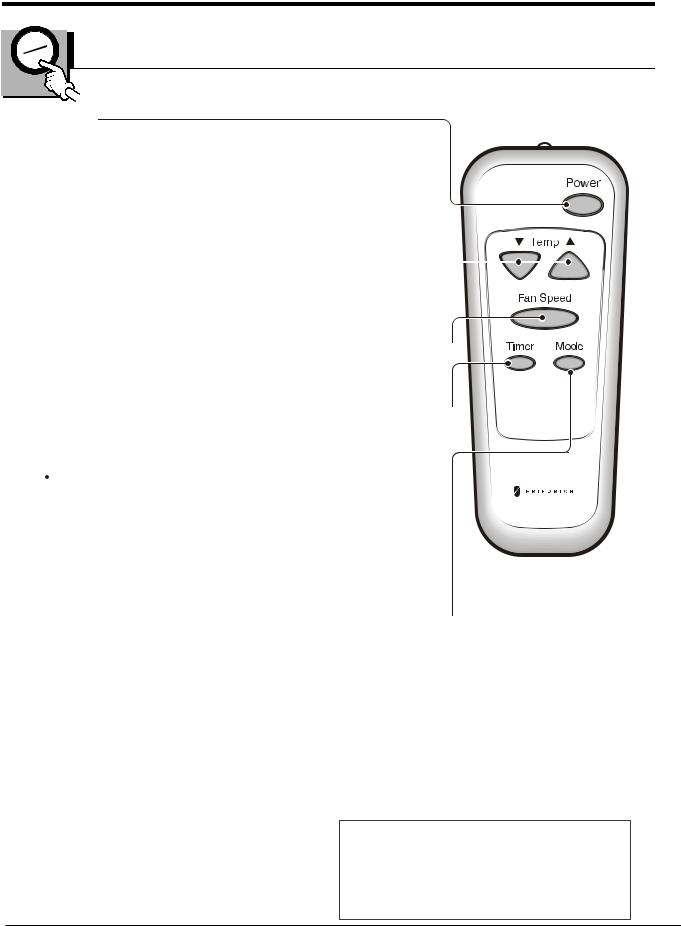
REMOTE CONTROL
POWER
 To turn the air conditioner ON,push this button.
To turn the air conditioner OFF,push the button again.
 This button takes priority over any other button.
TEMPERATURE SETTING
 Use this button to automatically control the temperature of the room.
The tmeperature can be set within a range of 60 F to 86 F by
increments of 1 F.
 The setting appears in the display.
FAN SPEED 
 Every time you push this button,it advances the setting as follows: {High[F2]
 Low[F1]}
 High[F2]
TIMER 
 SHUT-OFF TIME
 You will usually use shut-off time while you sleep.
 If unit is running,use Timer to set number of hours until shut-off.
For your sleeping comfort once Timer is set the Temperature setting will
raise 2 F after 30 min and once again after another 30 min.
 Push Timer button to advance setting from 1Hour→ 2Hour →...
→12Hours maximum.
 START TIME
 If unit is off,use Timer to set number of hours before nuit starts.
 Push Timer button to advance setting from 1Hour→ 2Hour →...
→12Hours maximum.
MODE 
 Push this button to shift mode of operation from COOL → MONEY SAVER→ FAN ONLY→HEAT
 COOL:
COOL:
 Fan runs continually for normal cooling operation.
 MONEY SAVER:
 The fan stops when the compressor stops cooling.Approximately every 3 minutes the fan will turn on and the nuit will check the room air temperature to determine if cooling is needed.
 FAN ONLY:
 Fan-only operation.
 HEAT:
HEAT:
 Fan runs continually for normal heating operation.
 CAUTION
When the air conditioner has been performed its cooling or feating operation and is turned off or set to the fan position wait at 3 minutes before resetting to the cooling operation again.
A slight heat odor may come from the nuit when first switching to HEAT after the cooling season is over.This odor,caused by fine duct particles on the heater,will disappear quickly.This is harmless.
Service Manual 8
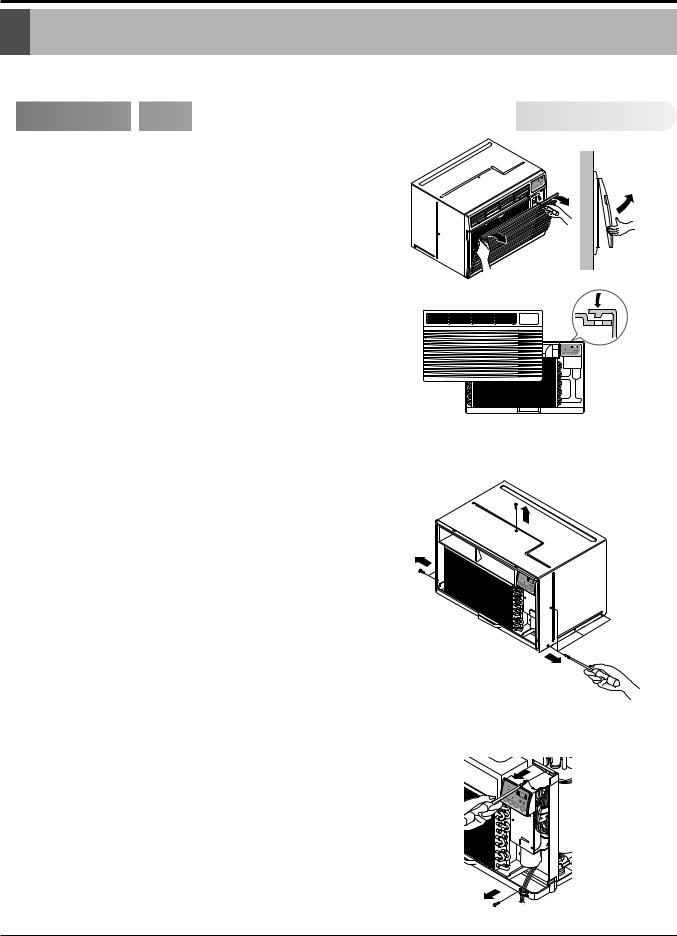
Disassembly Instructions
Disassembly Instructions
— Before the following disassembly, POWER SWITCH is set to OFF and disconnected the power cord.

 Mechanical
 Parts
Parts


1.FRONT GRILLE
1.Open the inlet grille upward or downward.
2. Remove the screw which fastens the front grille.
3. Pull the front grille from the right side.
4. Remove the front grille. (See Fig. 1)
5. Re-install the component by referring to the removal procedure.
FIG. 1
2.CABINET
1.After disassembling the FRONT GRILLE, remove the 9 screws which fasten the cabinet at the both sides and the top. (See Fig. 2)
Keep these for later use.
3.CONTROL BOX
1.Remove the front grille. (Refer to section 1)
2.Remove the screw which fasten the control box. (See Fig. 3)
3.Pull the control box from the barrier.(See Fig.3)
4.Discharge the capacitor by placing a 20,000 ohm resistor across the capacitor terminals.
5.Disconnect two wire housings in the control box.
6.Pull the control box forward completely.
7.Re-install the components by referring to the removal procedure. (See Fig. 3)
(Refer to the circuit diagram found on pages 24 in this manual and on the control box.)
FIG. 2
'F
OWER
FIG. 3
Service Manual 9
 Loading...