


Installation and Operation Manual
Room Air Conditioners
Standard Chassis Models
115-Volt: SS08, SS10, SS12, SS14
230-Volt: SS12, SS16, SM18, SM21, SM24
115-Volt: KS12, KS15
230-Volt: KM18, KM24
230-Volt: SL28, SL36
HEAVY DUTY
115-Volt: YS09
230-Volt: YS13, YM18, YL24, ES12, ES16, EM18, EM24, EL36
Register your air conditioner
Model information can be found on the name plate behind the front cover.
Please complete and mail the owner registration card furnished with this product, or register online at www.friedrich.com (USA only). For your future convenience, record the model information here.
Temperature |
|
|
Cooler |
Cool |
|
Fan |
Fan |
Only |
Speed |
Timer |
|
On/OffOperation |
|
Start |
Stop |
MODEL NUMBER
SERIAL NUMBER
PURCHASE DATE
 Warmer
Power
Money
Saver
Set Hr.
920-198-00 (8-06)

920-198-00
Congratulations!
You have purchased the very latest in room air conditioner technology. Your new Friedrich high efficiency room air conditioner will give you many years of dependable service. Many extra features have been built into your Friedrich air conditioner to assure quiet operation, the best circulation of cool, dry air, functional controls, and the most economical operation.
Table of contents |
|
Air Conditioner Operation |
|
Before Operating Your Unit........................................................................................................................................................................................................... |
2 |
For the best cooling performance and highest energy efficiency ................................................................................................................................................ |
3 |
How to operate your Friedrich room air conditioner ..................................................................................................................................................................... |
3 |
QuietMaster Programmable models |
|
To Start Unit ................................................................................................................................................................................................................................. |
3 |
To Set Mode of Operation ............................................................................................................................................................................................................. |
3 |
MoneySaver® Feature................................................................................................................................................................................................................... |
3 |
To Adjust Temperature ................................................................................................................................................................................................................. |
3 |
To Adjust Fan Speed..................................................................................................................................................................................................................... |
3 |
To Activate Smart Fan................................................................................................................................................................................................................... |
3 |
To Set Hour Clock ......................................................................................................................................................................................................................... |
3 |
To Set The Timer........................................................................................................................................................................................................................... |
4 |
Automatic Component Protection................................................................................................................................................................................................. |
4 |
How to Use the Remote Control................................................................................................................................................................................................... |
4 |
QuietMaster “K” & Heavy Duty Models / Twintemp |
|
To Start Unit ................................................................................................................................................................................................................................. |
5 |
To Set Mode of Operation ............................................................................................................................................................................................................. |
5 |
To Adjust Temperature ................................................................................................................................................................................................................. |
5 |
MoneySaver® Feature................................................................................................................................................................................................................... |
5 |
Care & Maintenance / Fresh Air & Exhaust Control |
|
Removing/Cleaning the Filter ....................................................................................................................................................................................................... |
6 |
Fresh Air & Exhaust Control ......................................................................................................................................................................................................... |
6 |
Air Conditioner Installation |
|
Electrical Requirements/Cabinet Dimensions.............................................................................................................................................................................. |
7 |
Installation Hardware.................................................................................................................................................................................................................... |
8 |
Standard Sash Window Installations............................................................................................................................................................................................ |
9 |
Through-the-wall Installations..................................................................................................................................................................................................... |
14 |
Troubleshooting Tips................................................................................................................................................................................................................... |
17 |
Accessories................................................................................................................................................................................................................................. |
17 |
Warranty ..................................................................................................................................................................................................................................... |
18 |
2
920-198-00
WARNING: Before operating your unit
Make sure the wiring is adequate for your unit.
If you have fuses, they should be of the time delay type. Before you install or relocate this unit, be sure that the amperage rating of the circuit breaker or time delay fuse does not exceed the amp rating listed in Figure 1.
DO NOT use an extension cord.
The cord provided will carry the proper amount of electrical power to the unit; an extension cord will not.
Make sure that the receptacle is compatible with the air conditioner cord plug provided.
This insures proper grounding. If you have a two prong receptacle you will need to have it replaced with a grounded receptacle by a certified electrician. The grounded receptacle should meet all national and local codes and ordinances. Under no circumstances should you remove the ground prong from the plug. You must use the three prong plug furnished with the air conditioner.
Test the power cord
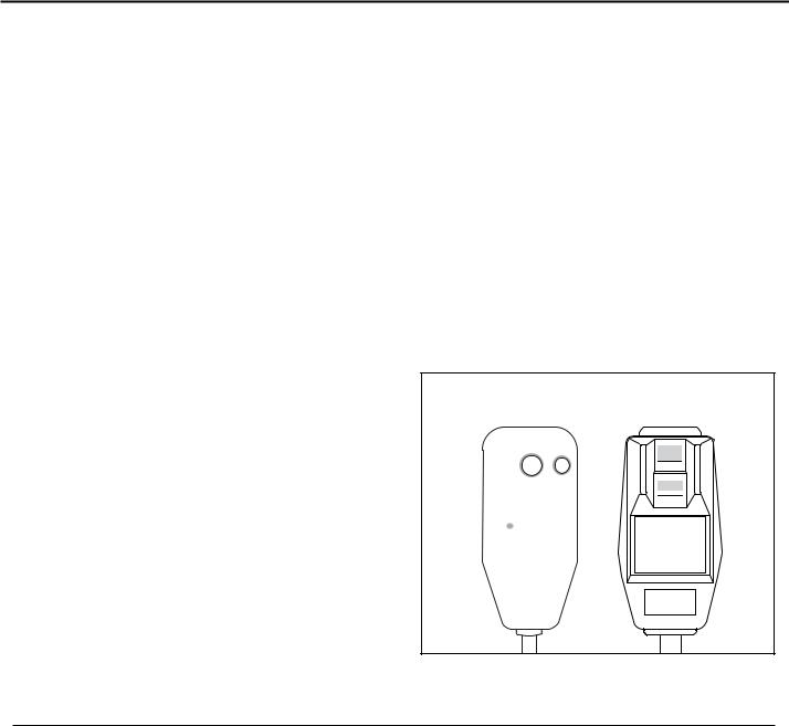
All Friedrich room air conditioners are shipped from the factory with a Leakage Current Detection Interrupter (LCDI) equipped power cord. The LCDI device meets the UL and NEC requirements for cord connected air conditioners effective August 2004.
To test your power supply cord:
1.Plug power supply cord into a grounded 3 prong outlet.
2.Press RESET (See Figure 2).
3.Press TEST (listen for click; Reset button trips and pops out).
4.Press and release RESET (listen for click; Reset button latches and remains in). The power supply cord is ready for operation.
NOTE: LCDI device is not intended to be used as a switch.
Once plugged in the unit will operate normally without the need to reset the LCDI device.
If the device fails to trip when tested or if the power supply cord is damaged it must be replaced with a new supply cord from the manufacturer. We recommend you contact our Technical Assistance Line at (800) 541-6645 ext. 845. To expedite service, please have your model and serial number available.
|
CIRCUIT RATING |
REQUIRED WALL |
|||
|
OR TIME DELAY |
RECEPTACLE |
|||
MODEL |
FUSE |
||||
|
|
||||
|
AMP |
VOLT |
NEMA |
|
|
|
NO. |
|
|||
|
|
|
|
||
SS08 • SS10 • SS12 • SS14 |
15 |
125 |
5-15R |
|
|
KS12 • KS15 • YS09 |
|
||||
|
|
|
|
||
|
|
|
|
|
|
SS12 • SS16 • SM18 |
15 |
250 |
6-15R |
|
|
SM21 • KM18 |
|
||||
|
|
|
|
||
|
|
|
|
|
|
SM24 • SL28 • KM24 |
20 |
250 |
6-20R |
|
|
YS13 • ES12 • ES16 |
|
||||
|
|
|
|
||
|
|
|
|
|
|
SL36 • YM18 • YL24 |
30 |
250 |
6-30R |
|
|
EM18 • EM24 • EL36 |
|
||||
|
|
|
|
||
|
|
|
|
|
|
Figure 1
NOTE: Your LCDI device will resemble one of these illustrations.
RESET
TEST
RESET
WARNING
TEST BEFORE EACH USE
1. PRESS RESET BUTTON
2. PLUG LDCI INTO POWER TEST RECEPTACLE
3.PRESS TEST BUTTON, RESET BUTTON SHOULD
 POP UP
4.PRESS TEST BUTTON, FOR USE
DO NOT USE IF ABOVE TEST
FAILS
WHEN GREEN LIGHT IS ON
IT IS WORKING PROPERLY
Figure 2
For the best cooling performance and highest energy efficiency
Keep the filter clean
Make sure that your air conditioner is always in top performing condition by cleaning the filter regularly. Instructions for removing and cleaning the filter can be found on page 7.
Insulation
Good insulation will be a big help in maintaining desirable comfort levels. Doors should have weather stripping. Be sure to caulk around doors and windows.
Provide good air flow
Make sure the airflow to and from the unit is clear. Your air conditioner puts the conditioned air out at the top of the unit, and takes in unconditioned air at the bottom. Airflow is critical to good operation. It is just as important on the outside of the building that the airflow around the unit exterior is not blocked.
Unit placement
If your air conditioner can be placed in a window or wall that is shaded by a tree or another building, the unit will operate even more efficiently. Using drapes or blinds on the sunny side of the dwelling will also add to your unit’s efficiency.
Proper installation of seal gasket
Make sure the seal gasket has been installed properly to minimize noise and improve efficiency. If the seal gasket has not been installed, please refer to Step 14 (page 13) of the installation instructions.
Also, if you switch from Cool mode to Fan Only, and switch back to COOL mode, there is a three minute delay before the compressor comes back on.
3
920-198-00
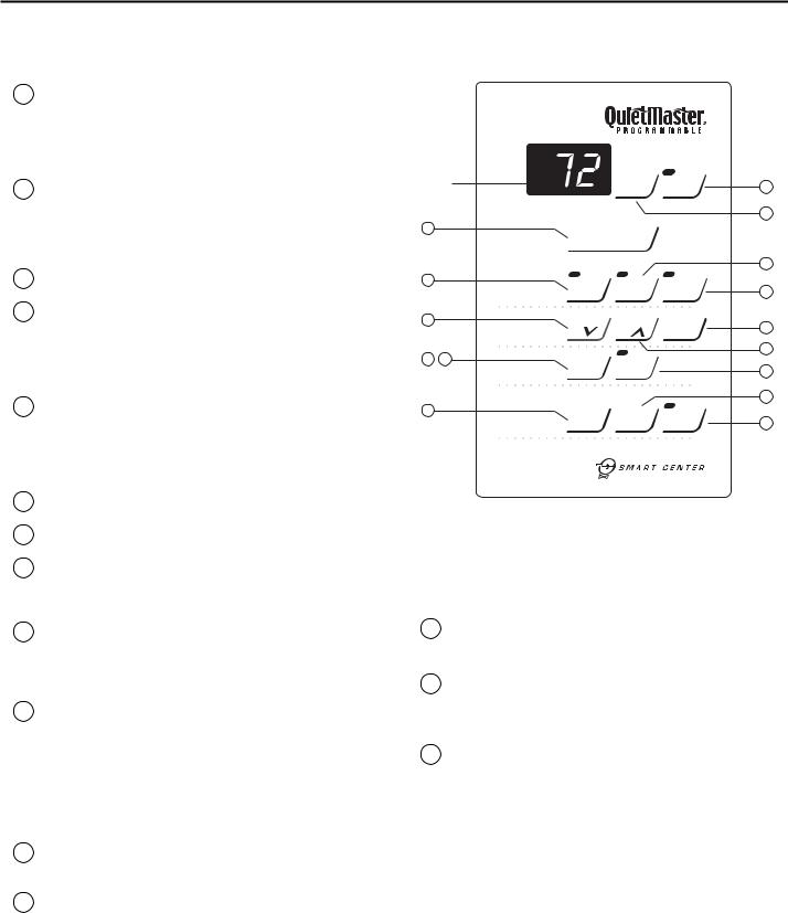
How to operate your Friedrich room air conditioner (QuietMaster Programmable)
To start unit
1If your air conditioner is installed and plugged into a proper receptacle, it is ready to go. Touch Power button once. The unit will automatically be in Cool mode with the temperature set at 75°F (24°C) and the fan speed at F1, the sleep setting. There is a 3- minute delay before the compressor will turn on. (See "Automatic Component Protection" on this page).
2Should the Check Filter light turn on when you first turn on the unit, touch Check Filter to turn off the light. Check Filter light will come on after 250 hours of use. (See page 7 for filter cleaning instructions.) Touch Check Filter to reset.
To set mode of operation
3When you first turn on the unit, it will be in the Cool mode (light on), with constant fan.
4Touch MoneySaver® (light on) to activate the MoneySaver® feature. This cycles the fan with the compressor so that the fan does not run all the time. This saves energy and improves dehumidification. (MoneySaver® will also run the fan to sample the return air temperature if the off cycle is too long). Or you may prefer constant fan for more air movement. To return to constant fan, touch Cool.
5Touch Fan Only (light on) if you want only the fan to run. You may want to use this feature in conjunction with the Fresh Air / Exhaust lever to bring outside air into a room, or to exhaust stale air. (See page 7, "Fresh Air and Exhaust Control" for more information.)
To adjust temperature [60°F (16°C) to 90°F (32°C)]
6COOLER – Touch  and hold until the display shows the desired room temperature.
7WARMER – Touch  and hold until the display shows the desired room temperature.
8FAHRENHEIT / CELSIUS – Touch ºF / ºC to show the temperature in Celsius, touch again to show Fahrenheit.
To adjust fan speed
9Touch 1-4 Speed to see current setting. Touch again to change speed. F1 is the lowest setting (SLEEP SETTING), F2 is low speed (LOW), F3 is medium speed (MED), F4 is high speed (HIGH).
To activate smart fan
10Touch Smart Fan (light on). Smart Fan will adjust the fan speed automatically to maintain the desired comfort level. For example, if the outside doors in your home are open for an extended period of time, or more people enter a room, Smart Fan may adjust to a higher fan speed to compensate for the increased heat load. This keeps you from having to adjust the fan speed on your own. Smart Fan cannot be activated in the Fan Only mode.
To deactivate smart fan
11 Touch 1-4 Speed, and select your desired fan speed.
Figure 3
DISPLAY |
|
|
Set |
Check |
2 |
||
|
|
|
|
Hour |
Filter |
||
|
|
|
|
|
|||
|
|
|
|
|
Press to reset |
12 |
|
|
|
|
|
|
|
|
|
1 |
|
|
|
|
|
|
|
|
|
|
|
|
|
|
4 |
3 |
|
|
|
Money |
Fan |
|
|
|
|
|
|
5 |
|||
|
|
|
|
Saver |
Only |
||
|
|
Mode |
|
® |
|
|
|
|
|
|
|
|
|
|
|
6 |
|
|
|
|
|
|
8 |
|
|
|
|
|
O |
O |
|
|
|
Temp |
|
|
F/ |
C |
|
|
|
|
|
|
|
7 |
|
|
|
|
|
|
|
|
|
9 |
11 |
|
1-4 |
Smart |
|
|
|
|
|
|
|
|
10 |
||
|
|
Fan |
Speed |
Fan |
|
|
|
|
|
|
|
|
|
|
|
|
|
|
|
|
|
|
14 |
13 |
|
|
A/C |
A/C |
Timer |
|
|
|
|
|
15 |
||||
|
|
Timer |
Stop |
Start |
On/ Off |
||
|
|
|
|
|
|
|
|
To set the timer
NOTE: Set Hour clock before attempting to set timer functions.
You can set the A/C Start and A/C Stop timer a minimum of one hour apart and a maximum of 23 hours apart.
13TIMER STOP - Press the A/C Stop button and continue pressing until the hour you want the unit to shut off appears in the display (A.M. or P.M.). The stop time for cooling will then be set.
14START TIME - Press A/C Start to view the current start time for cooling. Continue pressing until the hour you want the unit to start appears in the display (A.M. or P.M.). The start time for cooling will then be set.
15Press the Timer On/ Off button once to activate (light on) the timer function. Touch Timer On/ Off again (light off) to cancel the timer function if you so desire. Once the on and off times have been selected, they will remain in memory, and cycle daily until changed.
NOTE: If unit is unplugged or power is interrupted, the Set Hour button must be reset or the Timer On/ Off functions will not work.
To set hour clock
12Press Set Hour once to see the current clock setting. Continue pressing the button until the hour closest to the actual time appears in the display.
MAKE SURE YOU SET A.M. AND P.M. PROPERLY. A light will appear in the upper left corner of the display when the hour is P.M.
NOTE: Minutes will NOT show on display.
Automatic component protection
Your unit is equipped with Automatic Component Protection.
To protect the compressor of the unit, there is a three minute time delay if you turn the unit off or if power is interrupted. The fan will not be affected.
4
920-198-00
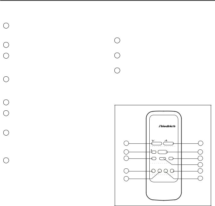
How to use the remote control* (QuietMaster Programmable)
To start unit
1POWER - Press the Power button once. The unit will automatically turn on in the mode and fan speed it was last left on.
To set mode of operation
2COOL - Press the Cool button to automatically switch the operating mode to COOL.
3FAN ONLY - Press the Fan Only button if you want to run the fan only. You may want to use this feature in conjunction with the Fresh Air/ Exhaust if you want to bring outside air into the room, or exhaust stale air. (The FRESH AIR / EXHAUST feature is located on the front of the air conditioner near the top. See Figure 9 on page 7.)
4MoneySaver® - Press the MoneySaver® button to activate the MoneySaver® feature. This cycles the fan with the compressor so that the fan does not run all the time.
To adjust temperature
To set the timer
NOTE: Set the hour clock before attempting to set timer functions. You can set the timer On/Off a minimum of one hour apart, and a maximum of 23 hours apart.
9TIMER START - Press Start to view the current start time for cooling. Continue pressing the Start button until you arrive at the start time you desire. The start time for cooling will then be set.
10TIMER STOP - Press the Stop button. Continue pressing the Stop button until you arrive at the stop time you desire. The stop time for cooling will then be set.
11TIMER ON/OFF - Press the On/off button once to activate (light on) or deactivate (light off) the timer. Once the Start and Stop times have been selected, they will remain in memory, and cycle daily until changed.
NOTE: If the unit is unplugged or the power is interrupted, the HOUR CLOCK must be reset or the Timer On/off functions will not work.
5COOLER - Press the  Cooler button to raise the temperature setting.
6WARMER - Press the  Warmer button to lower the temperature setting.
To adjust fan speed
7FAN SPEED - Press the Fan Speed button to see the current setting. Press again to change the fan speed. F1 is the lowest setting (SLEEP SETTING), F2 is low speed (LOW), F3 is medium (MED), and F4 is high (HIGH).
To set the hour clock
8SET HOUR CLOCK - Press Set Hour once to see the current clock setting. Continue pressing the button until you arrive at the current time.
MAKE SURE YOU SET THE A.M. AND P.M. PROPERLY. (NOTE: MINUTES ARE NOT SHOWN ON THE DISPLAY.) A light will appear in the upper left corner of the display when the hour is P.M.
*A Friedrich RC1 wireless remote control can be used to operate all QuietMaster® Programmable models.
Figure 4 |
|
|
|
|
Temperature |
|
|
|
|
Cooler |
|
Warmer |
|
|
6 |
|
|
|
5 |
Cool |
|
|
Power |
1 |
2 |
|
|
||
|
|
|
||
Fan |
Fan |
|
Money |
4 |
3 |
|
|
|
|
Only |
Speed |
Saver® |
|
|
Timer Operation |
|
|
7 |
|
On/Off |
Start |
Stop |
Set Hr. |
|
11 |
|
|
|
8 |
9 |
|
|
|
10 |
5
920-198-00
How to operate your Friedrich room air conditioner
(QuietMaster 'K' & Heavy Duty models / Twintemp models)
To start unit
If your air conditioner is installed and plugged into a properly grounded receptacle, it is ready to operate.
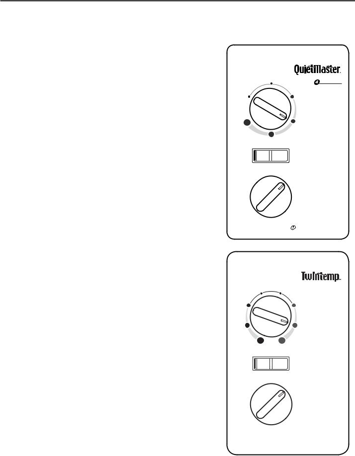
Mode control (QuietMaster ‘K’ and Heavy Duty)
The upper dial (Figure 5) allows you to select cooling at four different speeds, as well as Fan Only (Models SL28 and SL36 only have three cooling speeds.).
Off - to turn the unit off. High Cool - for quick cooling.
Medium Cool - to maintain a desired temperature. Low Cool - when cooling demand is low.
Sleep Setting - for nighttime use, or when cooling demand is low. Fan Only - to circulate air in the room without the compressor coming on.
The Fan Only setting can also be used with the Exhaust air setting to remove stale air or smoke from the room; or it can be used with the Fresh Air setting to bring outside air into the room. This is especially useful in the spring and fall when cooling may not be necessary. The Fresh Air and Exhaust controls are in the upper air discharge area. The center position of this control is the normal, or closed position, which recirculates air for maximum performance in the cooling mode (See Figure 9).
Mode control (Twintemp)
This dial allows you to select cooling or heating at three different speeds, as well as Fan Only (Figure 6).
Off - to turn the unit off.
High Cool or High Heat - for quick response.
Medium Cool or Medium Heat - to maintain a desired temperature. Low Cool or Low Heat - for nighttime use, or when demand is low. Fan Only - to circulate air in the room without the compressor coming on.
The Fan Only setting can also be used with the Exhaust air setting to remove stale air or smoke from the room, or it can be used with the Fresh Air setting to bring outside air into the room, especially in the spring and fall when cooling isn’t necessary.
The Fresh Air and Exhaust controls are in the upper air discharge area (see Figure 9, page 7). The center position of this control is the normal, or closed position, which recirculates air for maximum performance in the cooling mode.
NOTE: You may notice an odor when first activating the heat when the electric heat element comes on. This is due to dust burning off that may have gathered on the coil during the summer. This is normal.
Temperature control
The bottom dial on the control panel is the thermostat. Turn it clockwise for cooler temperature and counterclockwise for warmer.
Money Saver® switch
This rocker switch can be depressed to either Yes or No. In the Yes position you will get the most economical operation. Both the fan and compressor will cycle on and off together, maintaining the selected temperature at a more constant level and reducing the humidity more efficiently in the cooling mode. This control will only operate when the unit is in cooling or heating mode. In the No position, the fan will run constantly as long as the unit is in the cooling or heating mode.
NOTE: The YS09 is a 115 volt model and does not provide adequate heat below 37°F (3°C). This product is designed for warm climate applications.
Figure 5
Figure 6
S P E E D
|
Cool |
|
Yes |
No |
Money Saver® |
3 min. between restarts
Heat Cool
Yes |
No |
Money Saver® |
 Allow 3 min. between restarts
6
920-198-00
Care and Maintenance / Fresh air and exhaust control
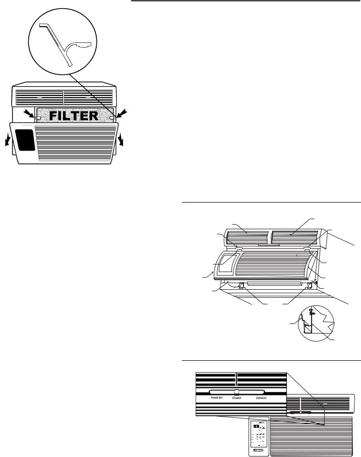
To remove, wash and replace filter and return air grille
Open the return air (RA) grille by grasping it at the top outside edges and pulling towards you (See Figure 7). The RA grille will stay open until it is detached or closed (it is easier to completely detach the grille before closing it). To remove the RA grille, grasp it at the bottom and pull towards you.
The filter is held in place by two spring clips (See Figure 7). Push down on the clips, grasp the filter and pull towards you to remove it for cleaning. Clean with warm water and a mild detergent, rinse, dry completely and replace. Use caution when removing the filter. The coil surface can be sharp.
If the RA grille has been removed, pick up the grille by supporting it from both sides near the bottom (See Figure 8, Note 1). Lift return air grille and insert the grille's tabs into the bottom slots of the discharge air plenum (See Figure 8, Note 2). Snap the grille into place by pushing the grille up and onto the unit's latches at the bottom (See Figure 8, Notes 3 and 4).
Fresh air and exhaust control
Your air conditioner has the ability to bring fresh air into the room or exhaust stale air out of the room. The control lever is found on the upper part of the unit (See Figure 9).
TO BRING IN FRESH AIR - Move the lever to the Fresh Air position which allows outside air to enter the room. This is useful in fall and spring as a means of bringing in fresh outside air when using Fan Only. It can also be used in the summer with the compressor in the Cooling Mode if you wish. Normally, for most efficient operation, cooling is accomplished with this control in the middle or closed position.
TO EXHAUST INDOOR AIR - Move the lever to the Exhaust position. This will allow stale air to be expelled to the outside of the dwelling. This is especially handy in the spring or fall when indoor air tends to get stale, or after a social gathering involving smokers, or to remove odors after cooking.
Figure 7
NOTE 2
DISCHARGE AIR PLENUM
SLOT
SLOT
TAB |
TAB |
|
|
NOTE 1 |
RETURN AIR GRILLE |
|
NOTE 1 |
NOTE 3 |
NOTE 3 |
|
|
|
LATCHES |
|
RETURN AIR GRILLE |
Figure 8
LATCH
NOTE 4
SIDE VIEW
Figure 9
7

920-198-00
Installation Instructions
NOTE: This manual includes installation instructions for window mount and thru-the-wall mount methods. TwinTemp® heat/cool units are designed for permanent thru-the-wall installation. Mounting the unit in a window will require a window mounting accessory kit, available through your Friedrich dealer.
Read This First! Electrical Requirements
IMPORTANT: Before you begin the actual installation of your air conditioner, check local electrical codes and the information below.
Your air conditioner must be connected to a power supply with the same A.C. voltage and hertz as marked on the data plate located on the chassis. Only alternating current (A.C.), can be used. Direct Current (D.C.) cannot be used. Refer to page 3 for the correct type of receptacle for your model.
CIRCUIT PROTECTION - USE ON SINGLE OUTLET CIRCUIT ONLY. An overloaded circuit will invariably cause malfunction or failure of an air conditioner, therefore, it is necessary that the electrical protection is adequate. Due to momentary high current demand when your air conditioner is started, use a "TIME DELAY" fuse or a HACR type circuit breaker. Consult your dealer or power company if in doubt.
Refer to the electrical data plate located on the air conditioner chassis to determine the correct fuse or circuit breaker amperage for your model (See Figure E on Page 16 for electrical receptacle location).
The power cord has a plug with a grounding prong of approved type and a matching receptacle is required.
WARNING: NEVER CUT OR REMOVE THE GROUNDING PRONG FROM THE PLUG. NEVER USE EXTENSION CORDS TO OPERATE AN AIR CONDITIONER.
The following instructions are for standard chassis model groups distinguished by the first two letters of the model designations and cabinet sizes listed below.
MODEL DESIGNATION |
CABINET SIZE (H x W x D) |
|
|
SMALL CHASSIS - SS, ES, YS, KS |
15 15⁄16" x 25 15⁄16" x 27 3⁄8" (405 mm x 660 mm x 695 mm) |
MEDIUM CHASSIS - SM, EM, YM, KM |
17 15⁄16" x 25 15⁄16" x 27 3⁄8" (455 mm x 660 mm x 695 mm) |
LARGE CHASSIS - SL, EL, YL |
20 3⁄16" x 28" x 33 5⁄8" (513 mm x 711 mm x 854 mm) |
8
920-198-00
Window Mount
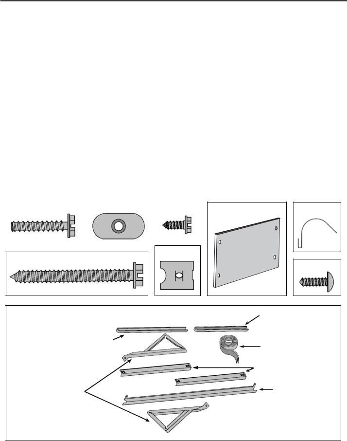
Installation Hardware
ITEM |
DESCRIPTION |
QTY. |
|
NO. |
|||
|
|
||
|
|
|
|
|
SHELL MOUNTING PARTS |
|
|
1 |
SUPPORT BRACKET |
2 |
|
2 |
SCREW, 10-24 x 1" HEX HEAD |
4 |
|
3 |
10-24 FLAT WELD NUT |
4 |
|
4 |
SCREW, SHEET METAL #12A x 2" |
7 |
|
|
|
|
|
|
WINGBOARD ANGLE MOUNTING |
|
|
5 |
WINGBOARD ANGLE, TOP |
1 |
|
6 |
WINGBOARD ANGLE, SIDE |
2 |
|
7 |
SCREW, SHEET METAL #8A x 3⁄ 8" |
2 |
|
|
WINGBOARD MOUNTING PARTS |
|
|
8 |
WINGBOARD (MASONITE) |
1 |
|
9 |
"J" TYPE SPEED NUT |
4 |
|
10 |
WINGBOARD CLIP (SPRING STEEL) |
4 |
|
11 |
SCREW, #8A x ½" PHILLIPS TRUSS HD. |
4 |
|
|
|
|
|
|
WINDOW SEALING |
|
|
12 |
SEALING GASKET (VINYL) |
1 |
|
13 |
WINDOW SEAL GASKET (DARK FOAM) |
1 |
|
14 |
CHASSIS SEAL GASKET (LIGHT FOAM) |
1 |
|
|
|
|
Thru-the-wall
Installation Hardware
ITEM |
DESCRIPTION |
QTY. |
|
NO. |
|||
|
|
||
|
|
|
|
|
MOUNTING PARTS |
|
|
4 |
SCREW, SHEET METAL #12A x 2" |
7 |
|
14 |
CHASSIS SEAL GASKET (LIGHT FOAM) |
1 |
|
|
|
|
ITEM #2 |
|
ITEM #3 |
|
ITEM #7 |
|
|
|
|
|
|
|
|
|
|
ITEM #9
ITEM #4
ITEM #8 |
ITEM #10 |
|
ITEM #11 |
ACCESSORY DETAIL |
ITEM #13 |
|
|
ITEM #14 |
ITEM #12 |
|
|
|
ITEM #6 |
ITEM #1 |
ITEM #5 |
NOT TO SCALE
9
920-198-00
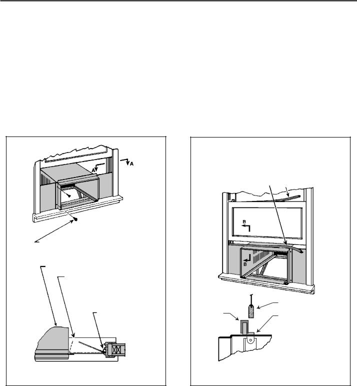
Standard Sash Window Installations
STEP 1 |
Remove decorative plastic return air grille to a safe area away |
STEP 5 Anchor the side angles (Item #6) by engaging the tabs at each |
|
from unit. The return air grille can be removed by pulling at the |
end of the sill plate (see Figure B) with the bottom loops of the |
|
sides on either the top or bottom. |
side angle. Engage the tabs at each end of the top angle (Item |
STEP 2 |
Also remove the installation hardware to a safe area away from |
#5) with the top loops of the side angle (see Figure B). Install |
two (2) screws (Item #7) to secure the top angle tabs and the |
||
|
the unit. |
side angle to the cabinet (see Figure B). |
STEP 3 |
Remove the chassis retainer by removing the far right screw |
STEP 6 Check the window sill and frame to be sure they are in good |
|
in the basepan (see Figure A); save this screw to reattach |
condition and firmly anchored to the wall. Repair if necessary. |
|
the chassis retainer after installation (Step 15). Also, remove |
STEP 7 CABINET MOUNTING – Raise the lower sash window ¼" |
|
and discard the two retainer screws and black plastic washers |
|
|
located at the rear of the unit. |
more than the height of the cabinet. Carefully slide the cabinet |
STEP 4 |
While an assistant holds the cabinet stationary, use the hand pull at |
through the open window until the sill plate channel rests behind |
the window sill and the top support rests against the window |
||
|
the front of the base pan, together with the pull strap (see Figure A) |
(see Figure C.) Center side to side and drill three (3) 5⁄ 32" dia. |
|
to pull the chassis out of the cabinet. REMOVE THE LARGE WHITE |
pilot holes into the window sill using the holes in the cabinet sill |
|
FOAM BLOCKS USED TO RESTRAIN THE COMPRESSOR |
plate as a guide. Install three (3) #12A x 2" long screws (Item |
|
DURING SHIPMENT. Inspect basepan for dislodged white blocks, |
#4, Figure C). |
|
and remove. Do not remove any other foam parts. |
|
Figure A |
HAND PULL |
FAR RIGHT |
SCREW |
CHASSIS |
RETAINER |
WIRE |
PULL STRAP |
Figure B
|
|
8A x ⅜" LONG SCREW |
CABINET |
TOP ANGLE (ITEM #5) |
(ITEM #7) 2 REQUIRED |
|
SIDE ANGLE |
|
|
(ITEM #6) 2 |
|
|
REQUIRED |
DETAIL B-1 |
TAB |
LOOP
SILL
PLATE TAB
DETAIL B-2
10
920-198-00
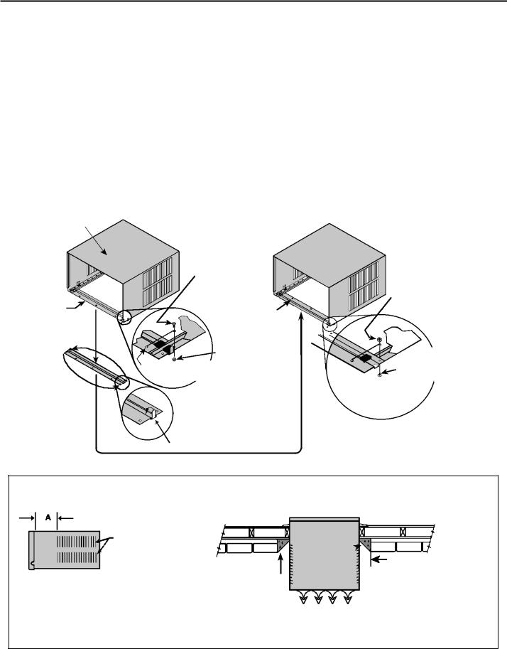
STEP 8 OUTSIDE SUPPORT MOUNTING – Assemble the support brackets (Item #1) to the bottom rails of the cabinet with four
(4) 10-24 1" long screws (Item #2) and four (4) 10-24 flat nuts (Item #3). Adjust the support brackets to bring the bottom pads in contact with the wall surface. (A 1" x 4" or 2" x 4" SPACER SHOULD BE USED BETWEEN THE WALL AND THE SUPPORT BRACKETS WHEN INSTALLED ON ALUMINUM OR VINYL SIDING). Drill 5⁄32" dia. pilot holes and secure the brackets to the wall with two (2) #12A x 2" long screws (Item #4). Adjust the support brackets to provide an approximate 3/8" down slope toward the outside for drainage. (See Figure D). Tighten all screws.
NOTE: The discharge air, return air, condenser air inlets and outlets must be unobstructed to avoid recirculation of rejected heated air.
Figure C
|
|
TOP |
|
CENTER |
SUPPORT |
||
CABINET IN |
ANGLE |
||
WINDOW SIDE |
PULL |
||
TO SIDE. |
|||
WINDOW |
|||
|
|
||
5 |
|
SASH DOWN |
|
32 |
BEHIND TOP |
||
DRILL (3) |
⁄ " |
||
PILOT HOLES |
SUPPORT |
||
AND INSTALL |
ANGLE |
||
(3) #12A x |
|
||
2" LONG |
SIDE |
||
SCREWS |
SUPPORT |
||
(ITEM #4) |
ANGLE |
||
WINDOW
SILL
LOCATE SILL PLATE GUIDE CHANNEL
JUST BACK OF WINDOW SILL
The following illustrations show a standard frame construction installation as well as some suggested ways of adapting the support bracket to thick walls and large stone ledges.
Figure D
⅜" DOWN SLOPE
SUPPORT BRACKET (ITEM #1)
#12A x 2" SCREW (ITEM #4)
1" x 4" OR 2" x 4" SPACER SHOULD BE USED BETWEEN WALL AND BRACKET WHEN INSTALLED
ON ALUMINUM, ASBESTOS OR VINYL SIDING
SUPPORT
BRACKET
10 – 24 FLAT WELD NUT (ITEM #3)
10 – 24 x 1" HEX HD. SCREW (ITEM #2)
Figure E
NOTE: It is not necessary to cut the wingboard for vertical height; only horizontal WIDTH Dimension “B”.
MEASURE DISTANCE "B" TO INSIDE OF THE
CHANNEL ON EACH SIDE
CUT HERE AND DISCARD CENTER WASTE MATERIAL.
WINGBOARD
SUBTRACT ⅛" FROM DIMENSION "B" AND MEASURE FROM THE EDGE OF THE WINGBOARD (ITEM # 8), MARK, SCORE AND CUT
WITH APPROPPRIATE CUTTING TOOL
11
920-198-00
Figure 1A TYPICAL MOUNTING SCHEME
SUPPLY AIR
RETURN AIR
10 - 24 SCREW
10 - 24 FLAT NUT ⅜" SLOPE DOWN
CONDENSER
AIR OUTLET
CONDENSER
AIR INLETS
#12A x 2" SHEET METAL SCREW
1" x 4" OR 2" x 4" SPACER BETWEEN WALL AND BRACKET SHOULD BE USED ON ALUMINUM, ASBESTOS OR VINYL SIDING.
Figure 2A MODIFIED MOUNTING SCHEME
CUT
HERE
DISCARD SHADED AREA
⅜" SLOPE DOWN
DIMENSION "A"
STONE LEDGE
OUTSIDE WALL
CUT TO FIT DIMENSION "A" AND BEND DOWN TO FORM A VERTICAL LEG.
Figure 3A TYPICAL MOUNTING SCHEME
STONE LEDGE |
⅜" SLOPE |
|
DOWN |
||
|
#12 x 2" SHEET METAL SCREW
2" x 4" SPACER
STEP 9 CUT WINGBOARD PANELS – Measure and cut the wingboard panels from the Masonite supplied (Item #8) to fit the spaces between the side window channels and the sides of the cabinet. (See Figure E).
NOTE: AFTER CUTTING THE PANELS, MAKE A TRIAL TEST TO SEE IF THEY FIT THE SPACE WITH ABOUT 1⁄8" CLEARANCE BEFORE GOING TO STEP 10.
STEP 10 ASSEMBLE THE CLIPS TO THE WINGBOARD PANELS-
Assemble the "J" type speed nuts (Item 9) and spring steel clips (Item 10) to the edges of the cut wingboard panels (See Figure F).
Figure 4A REVERSE SUPPORT BRACKET SCHEME
STONE LEDGE
⅜" SLOPE DOWN
STRAIGHTEN TAB TO LAY FLAT
ALONG THE BOTTOM RAIL OF
THE SHELL
SECURE THE LONGEST SIDE OF
THE BRACKET TO THE SHELL
ADJUST IN OR OUT TO REST
ON LEDGE
Figure F |
"J" TYPE SPEED NUT |
|
(ITEM #9) 2 REQUIRED |
CUT
WINGBOARD
PANEL
CENTER THE HOLE IN THE
SPEED NUT OVER THE SLOT IN
THE WINGBOARD PANEL
SPRING STEEL
CLIP (ITEM #10) 2
REQUIRED
3"
CUT EDGE
3"
SLIDE CLIP OVER
CUT EDGE OF
WINGBOARD
PANEL
12
920-198-00
STEP 11 INSTALL THE SIDE WINGBOARD PANELS – Be sure the cabinet has been secured to the window sill and that the outside support brackets have been installed as shown in Figure D. Raise the window sash and install the right and left side wingboard panels. (See Figure G).
STEP 12 INSTALL THE WINDOW SEALING GASKETS – Measure and cut the vinyl window seal gasket (grey color, Item # 12) to fit the width of the window, and install as shown in Figure H. Pull the window sash down behind the gasket. Measure and cut the dark foam window seal gasket (Item #13) and install it between the upper glass panel and the top part of the lower sash. (See Figure H).
NOTE: FOR REASONS OF SECURITY AND SAFETY, THE CUSTOMER MUST PROVIDE A MEANS OF PREVENTING THE WINDOW FROM OPENING.
Figure G
SECURE THE SIDE WINGBOARD PANELS TO
THE SIDE ANGLES WITH FOUR (4) #8 x ½" LONG
SCREWS (ITEM #11), TWO ON EACH SIDE.
TOP OF CABINET
PLACE WINGBOARD PANEL IN
WINDOW JAM TO COMPRESS THE
SPRINGS INSIDE THE RUNNERS,
AND SWING THE PANEL INTO PLACE
INDICATED BY THE DOTTED LINE.
WINDOW JAM
SECTION A - A
STEP 13 When possible, caulk the outside of the installation with industrial type caulking to prevent weather leaks.
STEP 14 INSTALL CHASSIS – After installing the shell, slide the chassis into the shell stopping approximately 3" from full insertion. Stuff the chassis seal gasket one inch deep between the chassis and the shell (see Figure I). Begin at either bottom corner and go up the side, across the top, and down the opposite side. Then push the chassis all the way into the shell for the remaining distance so that the plastic front meets the front edge of the shell.
If chassis seal gasket is not installed, the operation of the unit will be negatively affected. Operational noise and outside noise will also be amplified.
STEP 15 Reattach the chassis retainer wire with the same screw as in Step 3 (See Figure A).
Figure H
INSERT VINYL WINDOW SEAL |
|
|
GASKET OVER TOP ANGLE |
INSERT FOAM WINDOW |
|
TO WINGBOARD (ITEM #12) |
||
SEAL GASKET (ITEM # 13) |
||
|
|
LOWER WINDOW SASH |
|
VINYL |
TOP WINGBOARD ANGLE |
|
WINDOW |
||
|
||
GASKET |
|
SECTION B - B
13

920-198-00
STEP 16 OPTIONAL: The factory assembles the supply cord so that it exits the left side of the unit. At the consumer’s discretion, the supply cord can be made to exit the right side of the unit. To do this, remove the black rubber coated cord clamp from under the far left screw (See Figure I). Replace this screw back into the far left screw hole. Route the supply cord over the top of the return air grille latches and reattach the clamp to the adjacent screw hole (Figures I & J). Detach the right side cord clamp, route the supply cord through it and reattach. The supply cord should be pulled taut so as not to rest on the return air grille latches.
Figure I
FAR
LEFT
SCREW
ADJACENT
SCREW
HOLE
CHASSIS
SEAL
GASKET
WHEN INSTALLING CHASSIS SEAL GASKET,
BEGIN AT EITHER BOTTOM CORNER AND
GO UP THE SIDE, ACROSS THE TOP, AND
DOWN THE OPPOSITE SIDE.
STEP 17 Be sure the filter is in place before installing the return air grille (See Figure J), and that the electrical cord is properly routed so not to interfere with the installation. (See Step 16.)
STEP 18 Pick up the grille by supporting it from both sides near the bottom (See Figure K, Note 1.) Lift return air grille and insert the grille's tabs into the bottom slots of the discharge plenum (See Figure K, Note 2). Snap the grille into place by pushing the grille up and onto the unit's latches at the bottom (See Figure K, Notes 3 and 4).
STEP 19 Refer to the Operating Instructions beginning on page 3.
Figure J |
ADJACENT |
SCREW HOLE |
AIR FILTER |
CORD |
CLAMP |
RETURN AIR |
GRILLE LATCH |
RETURN AIR |
GRILLE LATCH |
CORD CLAMP |
Figure K
DISCHARGE |
NOTE 2 |
|
|
AIR PLENUM |
|
|
SLOT |
SLOT |
|
TAB |
TAB |
RETURN |
|
AIR |
|
|
|
|
|
RETURN |
GRILLE |
NOTE 1 |
|
|
AIR GRILLE |
|
|
|
(NOTE 1) |
LATCH |
NOTE 3 |
NOTE 3 |
NOTE 4 |
|
SIDE VIEW |
|
|
LATCHES |
|
14
920-198-00
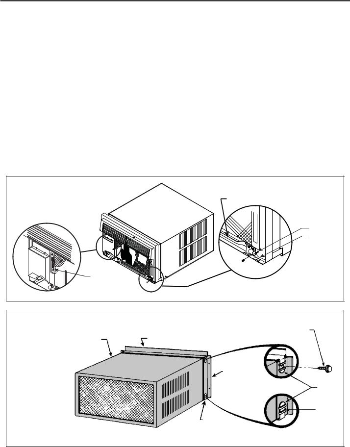
Through-the-wall Installations
The following instructions apply to wood, masonry, brick, concrete or cinder block wall construction
STEP 1 Follow steps 1, 2, 3 and 4 of the "STANDARD SASH WINDOW |
STEP 3 |
WALL PREPARATION – The maximum wall thickness permis- |
|
INSTALLATION" instructions beginning on page 10. |
|
sible without special construction is determined by the model size |
|
STEP 2 CABINET PREPARATION – Remove the sill plate from the |
|
to be installed. THE OUTSIDE CABINET CONDENSER-AIR- |
|
|
INTAKE-LOUVERS MUST NOT BE BLOCKED BY EXTENDING |
||
cabinet by removing the two nuts and screws retaining the sill |
|
||
|
INSIDE THE WALL AREA. Observe the maximum wall thickness |
||
plate. Note that the chassis retainer is secured by a right side |
|
||
|
shown in the chart and diagram in Figure B. |
||
nut and screw (See Detail 1, Figure A.) Bend the tabs of the |
|
||
|
|
||
sill plate down into its channel at both ends of the plate or cut |
|
SPECIAL INSTRUCTIONS FOR EXTRA THICK WALLS – |
|
them off (See Detail 2, Figure A.) Turn the sill plate end to end, |
|
||
|
For installation in walls exceeding the maximum thickness shown |
||
180° and reinstall. Reverse the orientation of nuts and screws |
|
||
|
in the chart, the following suggested construction may apply. |
||
so that the head of screw is on bottom of cabinet facing up and |
|
||
|
|
||
nut is on top facing down (See Detail 3, Figure A.) Insure that |
|
|
|
the chassis retainer is reinstalled as shown in the detail. |
|
|
|
|
|
|
|
Figure A |
BEFORE |
|
AFTER |
CABINET |
|
||
|
|
|
|
|
SCREW |
|
|
|
(2 REQUIRED) |
|
|
|
|
|
NUT |
|
DETAIL 1 |
|
(2 REQUIRED) |
SILL |
NOTE: HOLES |
|
|
PLATE |
|
|
|
|
MOVED TO |
|
|
|
|
|
|
TURN SILL PLATE |
|
BACK SIDE |
|
|
|
|
|
END TO END |
NUT |
|
DETAIL 3 |
|
(2 REQUIRED) |
||
|
|
||
|
RETAINER, CHASSIS |
|
SCREW |
|
THIS SIDE ONLY |
|
(2 REQUIRED) |
|
|
|
SCREW AND NUT |
|
|
|
ORIENTATION NOW |
|
|
|
REVERSED |
|
DETAIL 2 |
|
|
|
BEND TABS DOWN |
|
|
|
|
|
|
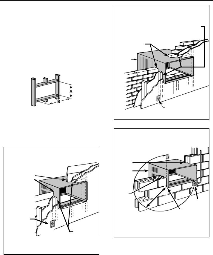
Figure B EXTRA THICK WALL CONSTRUCTION
MAXIMUM WALL THICKNESS
|
CONDENSER |
||
|
AIR INTAKE |
||
|
LOUVERS |
||
|
|
|
|
MODEL |
|
A |
|
SMALL CHASSIS |
|
7 ⅜" |
|
MEDIUM CHASSIS |
|
7 ⅜" |
|
LARGE CHASSIS |
|
15 ⅛" |
|
TOP VIEW SHOWING BEVELED SIDES FOR
AIR INTAKE. WALL
BELOW UNIT MUST BE
BEVELED ALSO.
TOP VIEW
CONDITIONED ROOM SIDE AIR
|
2" MINIMUM |
|
|
BOTH SIDES |
|
|
CONDENSER AIR |
|
|
INTAKE LOUVERS |
|
CONDENSER AIR |
NOTE: Condenser air inlets |
|
OUTLET / REJECTED |
and outlet must be unobstruct- |
|
HEATED AIR |
ed to avoid the recirculation of |
|
rejected heated air. |
||
|
15
920-198-00
STEP 4 CHECKING WIRING AND PLUMBING: Check all wiring and plumbing inside and outside of the wall to be sure none will be broken where the hole is to be cut.
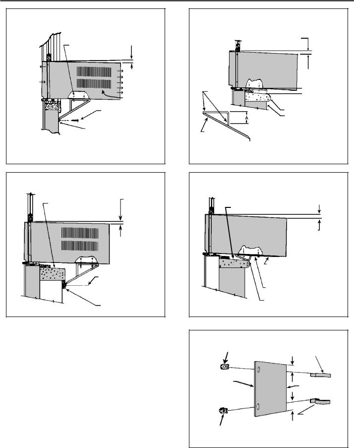
STEP 5 HOLE CONSTRUCTION: Depending upon size of unit to be installed, lay out the hole dimensions per the chart below. Cut and frame in hole to finished dimensions. Use 2" x 4" material for framing and follow the suggested typical installations in Figure C, D, or E.
NOTE: IF THE WALL CONSTRUCTION IS TYPICAL FRAME OR 2 x 4 STUDDING WITH BRICK OR STONE VENEERS, LOCATE THE HOLE NEXT TO ONE OF THE STUDS. FOR MASONRY, CONCRETE OR CINDER BLOCK WALLS, LOCATE HOLE FOR CONVENIENCE.
Figure D
BRICK VENEER CONSTRUCTION
SHIM VOID SPACES AT TOP AND
SIDES WITH WOOD AS REQUIRED
CAULK ALL SIDES
CABINET 
FINISHED |
SMALL |
MEDIUM |
LARGE |
DIMENSION |
CHASSIS |
CHASSIS |
CHASSIS |
A |
16 3⁄16" |
18 3⁄16" |
20 3⁄8" |
B |
26 3⁄16" |
26 3⁄16" |
28 1⁄4" |
NOTE: THESE DIMENSIONS ARE FOR FINISHED HOLE SIZE.
Figure C
FRAME WALL CONSTRUCTION
CAULK ALL SIDES
CABINET 
ELECTRICAL
RECEPTACLE (SEE FIG. E FOR
LOCATION NOTE)
SHIM THE VOID
SPACE AT THE
TOP AND SIDES
WITH WOOD AS REQUIRED
 ELECTRICAL RECEPTACLE
(SEE FIGURE E FOR LOCATION NOTE)
Figure E
SOLID MASONRY CONSTRUCTION
CAULK
ALL SIDES
CABINET
MORTAR
ELECTRICAL
RECEPTACLE
POINT "X"
NOTE: ELECTRICAL RECEPTACLE LOCATION FROM
POINT "X" MUST BE WITHIN A MAXIMUM RADIUS OF
69" FOR 115V UNITS AND 45" FOR 230V UNITS.
16
920-198-00
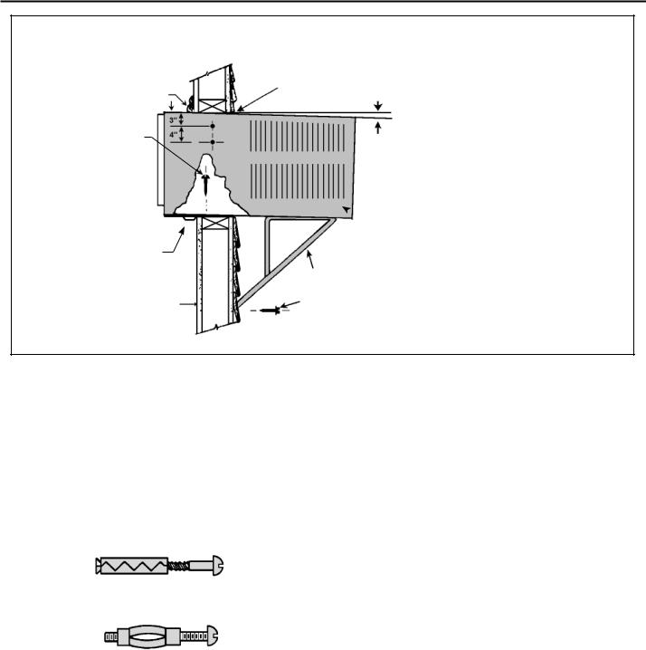
Figure F TYPICAL INSTALLATION
TRIM MOULDING
SCREW #12A x 2"
LONG (USE 3)
SILL PLATE GUIDE CHANNEL
INSIDE WALL SURFACE
CAULK ALL SIDES WEATHER TIGHT
⅜" SLOPE DOWN
NOTE: SUPPORT BRACKETS MAY BE OMITTED
FROM THROUGH-THE-WALL INSTALLATIONS IF THE
CABINET IS SECURED AS FOLLOWS. DRILL 2 HOLES IN EACH SIDE AND INSTALL 4 FASTENERS (2 EACH
SIDE). USE #12 x 2" SCREWS, TOGGLE BOLTS OR
EXPANSION ANCHOR BOLTS AS SHOWN IN STEP 7.  CABINET
SUPPORT BRACKETS (AVAILABLE AS OPTIONAL ACCESSORY)
SCREW #12 x 2" LONG, USE ONE EACH BRACKET.
DRILL 5⁄32 DIA. PILOT HOLES.
STEP 6 Slide the cabinet into the hole far enough to allow the guidechannel of the sill plate to contact the inside wall surface (See Figure F).
STEP 7 Drill three (3) 5 ⁄32" dia. pilot holes through holes in sill-plate into framing and install three (3) #12A x 2" long screws (See Figure F).
NOTE: ALTERNATE FASTENERS WHICH MAY BE USED FOR SECURING THE SILL PLATE IN THE WALL AND THE SUPPORT BRACKETS TO THE OUTSIDE WALL (NOT FURNISHED BUT AVAILABLE AT LOCAL HARDWARE STORE).
EXPANSION ANCHOR BOLT
MOLLY OR TOGGLE BOLT
STEP 8 Drill two (2) 5⁄32" dia. pilot holes each cabinet side at the locations shown (see Figure F) and install four (4) #12A x 2" screws (Item
# 4, page 9). Provided that Step 5 (hole construction) provides a sturdy mount with solid vertical studs, no support brackets are required. The installation must support the weight of the unit plus an additional weight of 400 pounds on the rear of the cabinet.
If support brackets are available, they can certainly be used for through-the-wall installations as shown in Figure F.
If the reliability of the wall is in question, a window installation kit which
includes support brackets can be ordered (see Accessories).
STEP 9 If desired, trim around the cabinet on the room side with a suitable frame moulding furnished by the installer (see Figure F).
STEP 10 Complete the installation by following steps 13 through 18 of SASH WINDOW INSTALLATION INSTRUCTIONS, pages 13-14.
STEP 11 Refer to the OPERATION SECTION for instructions.
17
 Loading...