


Installation and Operation Manual
Thru-the-Wall Conditioners
Air Conditioners and Heat Pumps
WallMaster |
|
230-Volt: WCT10, WCT12, WCT16, WET10, WET12, |
|
® |
115-Volt: WCT08, WCT10, WCT12 |
|
|
WET16, WHT12 |
|
|
|
93001017_00

Thank you for your decision to purchase the Friedrich High Efficiency Air Conditioner. Your new Friedrich has been carefully engineered and manufactured to give you many years of dependable, efficient operation, maintaining a comfortable temperature and humidity level. Many extra features have been built into your unit to assure quiet operation, the greatest circulation of cool, dry air, and the most economic operation.
THANK YOU, on behalf of our entire company, for making such a wise purchase.
UL |
|
MODEL NUMBER |
CONDITIONING . |
YS10M10A |
SAN ANTONIO, TEXAS |
SERIAL NUMBER |
ASSEMBLED IN MEXICO |
LICY00008 |
Register your air conditioner
Model information can be found on the name plate behind the front cover.
Please complete and mail the owner registration card furnished with this product, or register online at www.friedrich.com.
For your future convenience, record the model information here.
MODEL NUMBER
SERIAL NUMBER
PURCHASE DATE
Table of Contents |
|
Safety Precautions . . . . . . . . . . . . . . . . . . . . . . . . . . . . . . . . . . . . . . . . . . . . . . . . . . . . . . . . . . . . . . . . . . . . . . . . . . . . . . . . . . . . . . . |
4 |
WARNING: Before Operating Your Unit . . . . . . . . . . . . . . . . . . . . . . . . . . . . . . . . . . . . . . . . . . . . . . . . . . . . . . . . . . . . . . . . . . . . . . |
5 |
Standard Filter Cleaning / Installation Instructions . . . . . . . . . . . . . . . . . . . . . . . . . . . . . . . . . . . . . . . . . . . . . . . . . . . . . . . . . . . . |
6 |
Control Panel Operation . . . . . . . . . . . . . . . . . . . . . . . . . . . . . . . . . . . . . . . . . . . . . . . . . . . . . . . . . . . . . . . . . . . . . . . . . . . . . . . . . . |
7 |
New WallMaster Control Options . . . . . . . . . . . . . . . . . . . . . . . . . . . . . . . . . . . . . . . . . . . . . . . . . . . . . . . . . . . . . . . . . . . . . . . . . . . |
20 |
Wi-Fi Set-Up Instructions . . . . . . . . . . . . . . . . . . . . . . . . . . . . . . . . . . . . . . . . . . . . . . . . . . . . . . . . . . . . . . . . . . . . . . . . . . . . . . . . . |
21 |
Control Panel Operation Instructions .. . . . . . . . . . . . . . . . . . . . . . . . . . . . . . . . . . . . . . . . . . . . . . . . . . . . . . . . . . . . . . . . . . . . . . . |
22 |
Remote Control Operation . . . . . . . . . . . . . . . . . . . . . . . . . . . . . . . . . . . . . . . . . . . . . . . . . . . . . . . . . . . . . . . . . . . . . . . . . . . . . . . . |
23 |
Remote Effectiveness . . . . . . . . . . . . . . . . . . . . . . . . . . . . . . . . . . . . . . . . . . . . . . . . . . . . . . . . . . . . . . . . . . . . . . . . . . . . . . . . . . . . |
23 |
Airflow Selection and Adjustment. . . . . . . . . . . . . . . . . . . . . . . . . . . . . . . . . . . . . . . . . . . . . . . . . . . . . . . . . . . . . . . . . . . . . . . . . . . |
23 |
Installation Instructions . . . . . . . . . . . . . . . . . . . . . . . . . . . . . . . . . . . . . . . . . . . . . . . . . . . . . . . . . . . . . . . . . . . . . . . . . . . . . . . . . . |
24 |
Installation Instructions for WSE Sleeve . . . . . . . . . . . . . . . . . . . . . . . . . . . . . . . . . . . . . . . . . . . . . . . . . . . . . . . . . . . . . . . . . . . . . |
25 |
WallMaster Chassis Installation Instructions . . . . . . . . . . . . . . . . . . . . . . . . . . . . . . . . . . . . . . . . . . . . . . . . . . . . . . . . . . . . . . . . . |
27 |
Troubleshooting Tips . . . . . . . . . . . . . . . . . . . . . . . . . . . . . . . . . . . . . . . . . . . . . . . . . . . . . . . . . . . . . . . . . . . . . . . . . . . . . . . . . . . . . |
29 |
Warranty . . . . . . . . . . . . . . . . . . . . . . . . . . . . . . . . . . . . . . . . . . . . . . . . . . . . . . . . . . . . . . . . . . . . . . . . . . . . . . . . . . . . . . . . . . . . . . . |
31 |
2 |
3 |
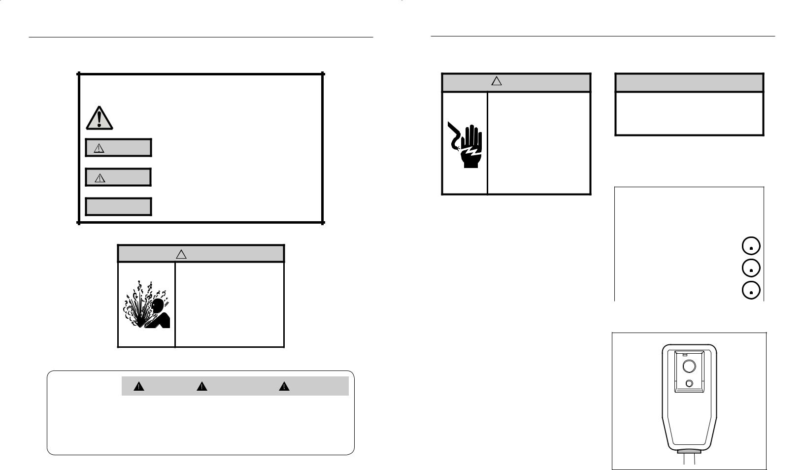
Safety Precautions
Your safety and the safety of others is very
important.
We have provided many important safety messages in this manual and on your appliance. Always read and obey all safety messages.
This is a safety Alert symbol.
This symbol alerts you to potential hazards that can kill or hurt you and others.
WARNING |
CAUTION |
NOTICE |
All safety messages will follow the safety alert symbol with the word “WARNING” or “CAUTION”. These words mean:
Indicates a hazard which, if not avoided, can result in severe personal injury or death and damage to product or other property.
Indicates a hazard which, if not avoided, can result in personal injury and damage to product or other property.
All safety messages will tell you what the potential hazard is, tell you how to reduce the chance of injury, and tell you what will happen if the instructions are not followed.
Indicates property damage can occur if instructions are not followed.
 WARNING
Refrigeration system under high pressure
Do not puncture, heat, expose to flame or incinerate.
Only certified refrigeration technicians should service this equipment.
R410A systems operate at higher pressures than R22 equipment. Appropriate safe service and handling practices must be used.
Only use gauge sets designed for use with R410A. Do not use standard R22 gauge sets.
|
|
|
WARNING |
AVERTISSEMENT |
ADVERTENCIA |
|
|
THINK |
|
||||
|
|
|
|
|
||
Do not remove, disable or |
Ne pas supprime, désactiver ou |
No eliminar, desactivar o pasar |
||||
|
SAFETY |
|||||
|
bypass this unit’s safety |
contourner cette l´unité des |
por alto los dispositivos de |
|||
|
FIRST |
devices. Doing so may cause |
dispositifs de sécurité, faire vous |
seguridad de la unidad. Si lo hace |
||
|
fire, Doing so may cause fire, |
risqueriez de provoquer le feu, les |
podría producirse fuego, lesiones |
|||
|
|
|
injuries, or death. |
blessures ou la mort. |
o muerte. |
|
|
|
|
|
|
|
|
WARNING: Before Operating Your Unit
 WARNING
Electrical Shock Hazard
Make sure your electrical receptacle has the same configuration as your air conditioner’s plug. If different, consult a Licensed Electrician.
Do not use plug adapters.
Do not use an extension cord.
Do not remove ground prong.
Always plug into a grounded 3 prong outlet. Failure to follow these instructions can result in death, fire, or electrical shock.
Make sure the wiring is adequate for your unit.
If you have fuses, they should be of the time delay type. Before you install or relocate this unit, be sure that the amperage rating of the circuit breaker or time delay fuse does not exceed the amp rating listed in Table 1.
DO NOT use an extension cord.
The cord provided will carry the proper amount of electrical power to the unit; an extension cord may not.
Make sure that the receptacle is compatible with the air conditioner cord plug provided.
Proper grounding must be maintained at all times. Two prong receptacles must be replaced with a grounded receptacle by a certified electrician.
The grounded receptacle should meet all national and local codes and ordinances. You must use the three prong plug furnished with the air conditioner. Under no circumstances should you remove the ground prong from the plug.
Test the power cord.
All Friedrich room air conditioners are shipped from the factory with a Leakage Current Detection Interrupter (LCDI) equipped power cord. The LCDI device on the end of the cord meets the UL and NEC requirements for cord connected air conditioners.
To test your power supply cord:
1.Plug power supply cord into a grounded 3 prong outlet.
2.Press RESET (see Figure 1).
3.Press TEST, listen for click; the RESET button trips and pops out.
4.Press and release RESET (Listen for click; RESET button latches and remains in). The power cord is ready for use.
NOTICE
Do not use the LCDI device as an ON/OFF switch.
Failure to adhere to this precaution may cause premature equipment malfunction.
Once plugged in, the unit will operate normally without the need to reset the LCDI device. If the LCDI device fails to trip when tested or if the power supply cord is damaged, it must be replaced with a new power supply cord from the manufacturer. Contact our Technical Assistance
Line at (800) 541-6645. To expedite service, please have your model number available.
Table 1
|
CIRCUIT RATING |
REQUIRED |
|||||||||
|
OR TIME DELAY |
WALL |
|||||||||
MODEL |
|
FUSE |
RECEPTACLE |
||||||||
|
AMP |
|
VOLT |
NEMA |
|
|
|
|
|
|
|
|
|
NO. |
|
|
|
|
|
|
|
||
|
|
|
|
|
|
|
|
|
|
|
|
|
|
|
|
|
|
|
|
|
|
|
|
WCT08, WCT10, |
|
|
|
|
|
|
|
|
|
|
|
WCT12 |
15 |
|
125 |
5-15P |
|
|
|
|
|
|
|
|
|
|
|
|
|
|
|
||||
|
|
|
|
|
|
|
|
|
|
|
|
WCT10, WCT12, |
|
|
|
|
|
|
|
|
|
|
|
WCT16 |
15 |
|
250 |
6-15P |
|
|
|
|
|
|
|
|
|
|
|
|
|
|
|
|
|
|
|
WET10, WET12, |
|
|
|
|
|
|
|
|
|
|
|
WET16, WHT12 |
20 |
|
250 |
6-20P |
|
|
|
|
|
|
|
|
|
|
|
|
|
|
|
||||
|
|
|
|
|
|
|
|
|
|
|
|
Figure 1
RESET
TEST
WARNING:
TEST BEFORE EACH USE!
1..PRESS REST BUTTON..
2..PLUG LCDI INTO POWER RECEPTACLE..
3..PRESS TEST BUTTON, RESET BUTTON SHOULD POP UP..
4..PRESS RESET BUTTON FOR USE..
DO NOT USE IF ABOVE
TEST FAILS..
WHEN GREEN LIGHT
IS ON, IT IS WORKING
PROPERLY!
FRR072
4 |
5 |

Standard Filter Cleaning / Installation Instructions
HOW TO CLEAN YOUR AIR FILTER
Your Friedrich room air conditioner is equipped with a permanent/ washable mesh air filter. The filter serves to remove dust, pollen, and other impurities from the air.
CHECK FILTER LIGHT
Your Friedrich room air conditioner is equipped with a check filter light that will illuminate after *45– 60 days of fan operation.
To reset the CHECK FILTER reminder press the CHECK FILTER button. (While the reminder is set for 45– 60 days of operation, we recommend checking the filter every 30 days for optimal performance.)
*Actual timer is set for 1000 hours of fan cycle operation.
FILTER ACCESS
Remove the FRONT PANEL. Using the handles, pull panel out until it is released from the two retaining snaps. Place the cover aside carefully. Remove the filter by pulling it from the handles releasing it from the slots on the frame. Wash the filter with water to remove all dust and then rinse, remove water excess and let it dry –do not twist – then replace the filter by inserting each tab in their respective slot.
Replace the FRONT PANEL by positioning one of the sides in the snaps of the handle first and then the other side, make sure that both snaps are correctly aligned and the logo is in the right position.
Figure 2
FRR071
6
Control Panel Operation
All of the control panel function buttons and mode icons can be viewed in Figure 3.
Power On – Press the button to turn on the air conditioner. The power button illuminates to indicate that the power is on. The backlight on the power switch will automatically turn off after 20 seconds of inactivity. The remote control can also be used to turn power ON / OFF (See Remote Control).
Display – The display is a high efficiency LCD with a built-in backlight. After 20 seconds of inactivity, the display switches off. Touching any button automatically changes the display to full brightness.
There are three control push buttons on each side of the display.
Figure 3 |
|
|
|
|
|
|
SYSTEM |
FAN MODE |
FAN SPEED |
TEMPERATURE |
TIMER |
IR WINDOW |
ON / OFF |
Cycles between |
Sets fan to either: |
Sets fan speed: |
Increment UP |
Turns ON or OFF |
Do not block |
Turns unit on/ off |
AUTO, HEAT, |
- Cycle automatically |
LOW, MED, |
|
|
|
|
COOL, or FAN |
- Run continuously |
HIGH or AUTO |
TEMPERATURE |
|
|
|
ONLY |
|
(if equipped) |
Increment DOWN |
|
|
|
(if equipped) |
|
|
|
|
|
|
|
|
|
|
|
|
|
|
|
|
|
|
|
|
|
|
|
|
|
|
|
|
|
|
|
|
|
|
|
|
|
|
|
|
|
|
|
|
|
|
|
|
|
|
|
|
|
|
|
|
|
|
|
|
|
|
|
|
|
|
|
|
|
|
|
|
|
|
|
|
|
|
|
|
|
|
|
|
|
|
|
|
|
|
|
|
|
|
|
|
|
|
|
|
|
|
|
|
|
|
|
|
|
|
|
|
|
|
|
|
|
|
|
|
|
|
|
|
|
|
|
|
|
|
|
|
|
|
|
|
|
|
|
|
|
|
|
|
|
|
|
|
|
|
|
|
|
|
|
|
|
|
|
|
|
|
|
|
|
|
|
|
|
|
|
|
|
|
|
|
|
|
|
|
|
|
|
|
|
|
|
|
|
|
|
|
|
|
|
|
|
|
|
|
|
|
|
|
|
|
|
|
|
|
|
|
|
|
|
|
|
|
|
|
|
|
|
|
|
|
|
|
|
|
|
|
|
|
|
|
|
|
|
|
|
|
|
|
|
|
|
|
|
|
|
|
|
|
|
|
|
|
|
|
|
|
|
|
|
|
|
|
|
|
|
|
|
|
|
|
|
|
|
|
|
|
|
|
|
|
|
|
|
|
|
|
|
|
|
|
|
|
|
|
|
|
|
|
|
|
|
|
|
|
|
|
|
|
|
|
|
|
|
|
|
|
|
|
|
|
|
|
|
|
|
|
|
|
|
|
|
|
|
|
|
|
|
|
|
|
|
|
|
|
|
|
|
|
|
|
|
|
|
|
|
|
|
|
|
|
|
|
|
|
Figure 4 |
COOL HEAT FAN ONLY -AUTO- |
ON / OFF |
DISCONNECTED |
|
CONTROL |
|
WI-FI OPERATING |
|
|||||||||||||||||||
|
|
|
|
Automatically switches |
Turns unit on/off |
FROM POWER BOARD |
|
LOCKED |
|
STATE |
|
||||||||||||||||
|
|
|
|
between cool & heat |
|
|
|
|
|
|
|
|
|
|
|
|
|
|
|
|
|
|
|
|
|
|
|
|
|
MODE |
|
|
|
|
|
|
|
|
|
|
|
|
|
|
|
|
|
|
|
|
|
|
|
||
|
|
Cycles between |
|
|
|
|
|
|
|
|
|
|
|
|
|
|
|
|
|
|
|
|
|
|
|
||
|
|
|
|
|
|
|
|
|
|
|
|
|
|
|
|
|
|
|
|
|
|
|
|
|
|||
|
|
COOL, HEAT, FAN |
|
|
|
|
|
|
|
|
|
|
|
|
|
|
|
|
|
|
|
|
|
|
|
||
|
|
ONLY or -AUTO- |
|
|
|
|
|
|
|
|
|
|
|
|
|
|
|
|
|
|
|
|
|
|
|
||
|
|
(if equipped) |
|
|
|
|
|
|
|
|
|
|
|
|
|
|
|
|
|
|
|
TEMPERATURE |
|
||||
|
|
|
|
|
|
|
|
|
|
|
|
|
|
|
|
|
|
|
|
|
|
|
|
UP |
|
||
|
|
FAN |
|
|
|
|
|
|
|
|
|
|
|
|
|
|
|
|
|
|
|
|
TEMPERATURE |
|
|||
|
|
|
|
|
|
|
|
|
|
|
|
|
|
|
|
|
|
|
|
|
|
|
|||||
|
|
Sets fan to either: |
|
|
|
|
|
|
|
|
|
|
|
|
|
|
|
|
|
|
|
|
|
||||
|
|
|
|
|
|
|
|
|
|
|
|
|
|
|
|
|
|
|
|
|
|
|
|||||
|
|
- Automatically cycle |
|
|
|
|
|
|
|
|
|
|
|
|
|
|
|
|
|
|
|
|
DOWN |
|
|||
|
|
- Continuously run |
|
|
|
|
|
|
|
|
|
|
|
|
|
|
|
|
|
|
|
|
|
|
|
|
|
|
|
|
|
|
|
|
|
|
|
|
|
|
|
|
|
|
|
|
|
|
|
|
|
|
|
|
|
|
|
FAN SPEED |
|
|
|
|
|
|
|
|
|
|
|
|
|
|
|
|
|
|
|
TIMER |
|
||||
|
|
Sets fan speed: |
|
|
|
|
|
|
|
|
|
|
|
|
|
|
|
|
|
|
|
shows on or off |
|
||||
|
|
LOW, MED, HIGH, |
|
|
|
|
|
|
|
|
|
|
|
|
|
|
|
|
|
|
|
|
|
|
|
||
|
|
OR MAX |
|
|
|
|
|
|
|
|
|
|
|
|
|
|
|
|
|
|
|
|
|
|
|
||
|
|
(Actual settings are |
|
|
|
|
|
|
|
|
|
|
|
|
|
|
|
|
|
|
|
|
|
|
|
||
|
|
model dependant) |
|
|
|
|
|
|
|
|
|
|
|
|
|
|
|
|
|
|
|
|
|
|
|
||
|
|
|
|
|
|
|
|
|
|
|
|
|
|
|
|
|
|
|
|
|
|
|
|
FILTER |
|
||
|
|
|
|
|
|
|
|
|
|
|
|
|
|
|
|
|
|
|
|
|
|
|
|
Check / clean |
|
||
|
|
|
|
|
2 DIGIT DISPLAY |
|
|
|
|
|
|
|
|
|
|
|
|
|
|
|
|||||||
7

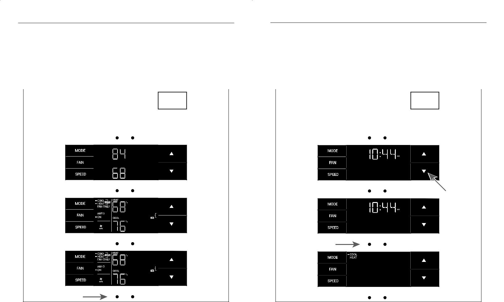
Control Panel Operation
Accessing Sub-Menus
The leftmost MENU button accesses the sub-menu. See Figure 5. The arrow buttons navigate the 6 menu options (See Figure 6):
– LIM |
– LOCK |
– TM |
– CnCT |
– F-C |
– diAG |
Control Panel Operation
Navigating Inside the Sub-Menus
The leftmost MENU button moves you forward through the sub-menu. See Figure 8.
The rightmost button moves you backward once inside the LIM and TM menus. See Figure 9.
The rightmost button exits the menu. See Figure 7.
Figure 5 |
Figure 8 |
|
|
|
|
|
|
|
|
|
|
|
|
|
|
|
|
|
|
|
|
|
|
|
|
|
|
|
|
|
|
MENU |
|
|
|
|
MENU |
|
|
||||
|
|
|
|
|
|
|
|
|
|
|
|
|
|
|
|
|
|
|
|
|
|
|
|
|
|
|
|
Figure 6 |
|
|
|
|
|
|
Figure 9 |
|
|
|
|
|
|
|
|
|
|
|
|
|
|
|
|||||
|
|
|
|
|
|
|
|
|
|
|
|
|
|
|
|
|
|
|
|
|
|
|
|
|
|
|
|
|
|
|
|
|
|
|
|
|
|
|
|
|
|
|
|
|
|
|
|
|
|
|
|
|
|
|
|
|
|
|
|
|
|
|
|
|
|
|
|
|
|
MENU |
MENU |
Figure 7
MENU
8 |
|
9 |
Control Panel Operation |
|
|
|
|
|
Control Panel Operation |
|
|
|
|
|||||
The LIM Menu |
|
|
|
|
|
The TM Menu |
|
|
|
|
|||||
This is the limit menu. See Figure 10. |
Then you can set the higher setpoint limit using the arrow buttons. |
|
This is the TM menu used to set a timer. See Figure 14. |
Using the leftmost button, you switch to the minutes and complete setting |
|||||||||||
Upon entering the menu, the first option will be to set the lower setpoint |
See Figure 12. |
|
In the menu, you set the current time using the arrow buttons. See Figure |
the time. See Figure 16. |
|||||||||||
|
|
|
|
|
|
|
|
|
|||||||
limit using the arrow buttons. See Figure 11. |
Pressing the leftmost button completes the limit setting. See Figure 13. |
|
15. (Note: These two “set clock” steps will be skipped if the unit is already |
You select your mode. Either cool, heat, or auto. Toggle these using the |
|||||||||||
|
|
|
|
|
|
|
|
connected to Wi-Fi.) |
arrow buttons. See Figure 17. (Note: cooling-only models skip this step.) |
||||||
|
|
|
|
|
|
|
|
First, set the hour. |
The process is the same for all three modes. Auto mode will be shown as |
||||||
|
|
|
|
|
|
|
|
|
|
|
|
the example. |
|||
|
|
|
|
|
|
|
|
|
|
|
|
|
|
|
|
Figure 10 |
|
|
|
|
|
|
|
Figure 14 |
|
|
|
|
|
|
|
|
|
|
|
|
|
|
|
|
|
|
|
||||
|
|
|
|
|
|
|
|
|
|
|
|
|
|
|
|
|
|
|
|
|
|
|
|
|
|
|
|
|
|
|
|
|
|
|
|
|
|
|
|
|
|
|
|
|
|
|
|
|
|
|
|
|
|
|
|
|
|
|
|
|
|
|
|
|
|
|
|
|
|
|
|
|
|
|
|
|
|
|
|
MENU |
MENU |
Figure 11 |
Figure 15 |
MENU |
MENU |
Figure 12 |
Figure 16 |
MENU |
MENU |
Figure 13 |
Figure 17 |
MENU |
MENU |
10 |
11 |
 Loading...