


Friedrich VEA09K25, VEA09K34, VE09K50, VEA12K25, VEA12K34 Operation Guide
...INSTALLATION &
OPERATION GUIDE
VERT-I-PAK® A-SERIES
SINGLE PACKAGE
VERTICAL AIR
CONDITIONING SYSTEM
9,000 - 18,000 BTU/h
920-075-09 (11-07)

|
920-075-09 |
|
Table of Contents |
Installation Recommendations.................................................................................................................................................... |
3 |
General Specifications |
|
Model Number Identification Guide................................................................................................................................................. |
4 |
VERT-I-PAK Chassis Specifications................................................................................................................................................ |
4 |
Electrical Data............................................................................................................................................................................... |
4-5 |
Installation |
|
Utility Closet Dimensions.................................................................................................................................................................. |
6 |
Wall Plenum & Architectural Louver Installation.............................................................................................................................. |
7 |
Drain Pan Installation....................................................................................................................................................................... |
8 |
Condensate Disposal Sysatem........................................................................................................................................................ |
8 |
Indoor Return Air Grille Installation.................................................................................................................................................. |
8 |
Chassis Installation........................................................................................................................................................................... |
9 |
Remote Thermostat Operation |
|
Remote Thermostat........................................................................................................................................................................ |
10 |
Thermostat Connections................................................................................................................................................................ |
10 |
Desk Control Terminals.................................................................................................................................................................. |
10 |
Auxiliary Fan control....................................................................................................................................................................... |
10 |
Electrical and Thermostat Wiring Diagrams................................................................................................................................... |
11 |
Chassis Operation |
|
Fresh Air Door................................................................................................................................................................................ |
12 |
Low Ambient Protection................................................................................................................................................................. |
12 |
Room Freeze Protection................................................................................................................................................................ |
12 |
Emergency Heat Override.............................................................................................................................................................. |
12 |
Emergency Heat Operation............................................................................................................................................................ |
12 |
Service |
|
Servicing/Chassis Quick Changeouts........................................................................................................................................... |
13 |
Routine Maintenance..................................................................................................................................................................... |
13 |
Error Codes.................................................................................................................................................................................... |
14 |
Factory Dipswitch Configuration.................................................................................................................................................... |
14 |
Accessories.................................................................................................................................................................................... |
15 |
Warranty........................................................................................................................................................................................ |
16 |
Please read this manual thoroughly prior to equipment installation or operation. It is the installer’s responsibility to properly apply and install the equipment. Installation must be in conformance with the NFPA 70-2002 National Electric Code or current edition and Universal Mechanical Code current edition and applicable local or national codes.
Proper installation is not difficult, but it is essential.
2

920-075-09
Vert-I-Pak Installation Recommendations
For proper unit performance and maximum operating life please refer to the minimum installation clearances below.
Figure 1
VERT-I-PAK® units must be installed on an outside wall. Confined spaces and/or covered areas should be avoided. Units should be installed no closer than 12" apart when two units are side by side. If three of more units are to operate next to one another allow a minimum of 60" between units or pairs of units. Also, a vertical clearance of 60" should be maintained between units. Units installed on the bottom floor should be mounted at least 6" off of the ground.
6" |
|
B |
|
|
60" 60" |
A |
|
|
|
SMALL RECESS OK |
LARGER RECESS OK. IF A> 5xB |
60" |
60" |
|
|
|
|||
60" |
|
|
60" |
|
|
|
|
|
|
60" |
60" |
|
60" |
|
|
|
|
|
|
60" |
60" |
|
|
|
6" |
6" |
|
|
12" |
|
|
|
|
Figure 2
Any time obstructions are present use the following guidelines for proper spacing from the VERT-I-PAK louver:
•For minor obstructions such as lamp poles or small shrubbery a clearance of 24" from the outdoor louver should be maintained.
•For major obstructions such as a solid fence, wall or other heat rejecting device like a condensing unit, a minimum distance of 72" should be kept.
BUILDING
|
60" |
24" |
|
VPAK |
12" |
VPAK |
VPAK |
|
|
|
24" |
|
POLE |
|
SHRUB |
|
|
|
|
OUTDOOR |
|
|
72" |
CONDENSING |
|
|
|
UNIT |
FENCE |
|
|
|
MAJOR OBSTRUCTION |
The above suggestions are for reference only and do not represent all possible installations. Please contact the factory for information regarding affects of other installation arrangements.
By following these simple recommendations you can be confident that your Friedrich Vert-I-Pak® will provide years of worry-free operation.
3
920-075-09
GeneralSpecifications
Vert-I-Pak® ModelIdentificationGuide
MODEL NUMBER |
V |
E |
A |
09 |
K |
34 |
RT |
H |
|
SERIES |
|
|
|
|
|
|
|
|
ENGINEERING CODE |
V=Vertical Series |
|
|
|
|
|
|
|
OPTIONS |
|
|
|
|
|
|
|
|
|
|
|
E =Cooling with electric heat |
|
|
|
|
|
|
|
RT = Standard Remote Operation |
|
H =Heat Pump |
|
|
|
|
|
|
|
|
|
|
|
|
|
|
|
ELECTRIC HEATER SIZE |
|||
|
|
|
|
|
|
|
|||
DESIGN SERIES |
|
|
|
|
|
||||
|
|
|
|
|
A Series |
||||
A = 32"/47" Cabinet |
|
|
|
|
|
25 = |
2.5 KW |
||
|
|
|
|
|
|
|
34 = |
3.4 KW |
|
NOMINAL CAPACITY |
|
|
|
|
|
||||
|
|
|
|
|
50 = |
5.0 KW* |
|||
A Series (Btu/h) |
|
|
|
|
|
|
|||
|
|
|
|
|
|
75 = |
7.5 KW** |
||
09 = 9,000 |
18 = 18,000 |
|
|
|
|
|
|||
|
|
|
|
|
|
|
|
||
12 = 12,000 |
24 = 24,000 |
|
|
|
|
|
Refer to electrical data chart for heater/unit compatibility. |
||
|
|
|
|
|
|
|
* Not available on 9000 BTU models. |
||
VOLTAGE |
|
|
|
|
|
|
|||
K = 208/230V-1Ph-60Hz |
|
|
|
|
|
** 24000 BTU only. |
|||
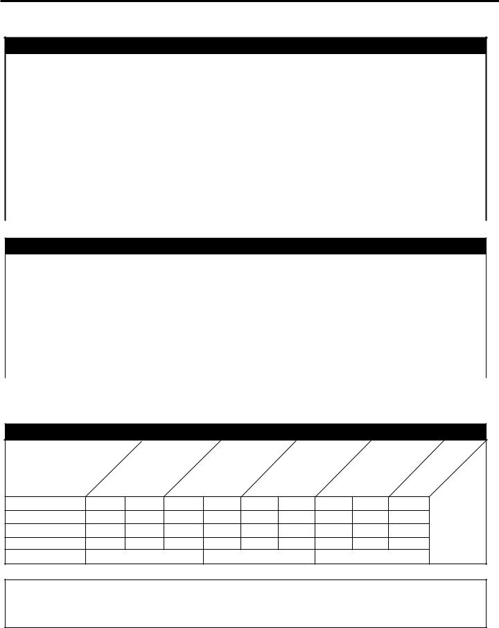
Electrical Data
MODEL: |
V(E,H)A09 |
V(E,H)A12 |
V(E,H)A18 |
Voltage (V) |
230 / 208 |
230 / 208 |
230 / 208 |
Refrigerant |
R-22 |
R-22 |
R-22 |
Chassis Width |
23.125" |
23.125" |
23.125" |
Chassis Depth |
23.125" |
23.125" |
23.125" |
Chassis Height ** |
32.25" |
32.25" |
32.25" |
Shipping W x D x H |
26.00" x 28.50" x 35.00" |
26.00" x 28.50" x 35.00" |
26.00" x 28.50" x 35.00" |
Supply Duct Collar *** |
10" |
10" |
10" |
Drain Connection |
3/4" FPT |
3/4" FPT |
3/4" FPT |
Min. Circuit Amps |
|
See Chassis Nameplate |
|
CFM Indoor |
|
See Charts 2 & 3 (Page 10) |
|
Max. Duct ESP |
.3 in. water |
.3 in. water |
.3 in. water |
NOTES:
**Height includes 2" duct collar & isolators under unit.
***Factory collar accepts 10" flex duct.
ChassisSpecifications
Model |
V(E,H)A09K25V(E,H)A09K34V(E,H)09K50V(E,H)A12K25V(E,H)A12K34V(E,H,)A12K50V(E,H)A18K25V(E,H)A18K34V(E,H)A18K50 |
||||||||
|
|||||||||
Voltage ( V) |
230/208 |
230/208 |
230/208 |
230/208 |
230/208 |
230/208 |
230/208 |
230/208 |
230/208 |
LRA - Comp. (A) |
21 |
21 |
21 |
24.0 |
24.0 |
24.0 |
47 |
47 |
47 |
Cooling Current (A) |
4.4/4. 9 |
4.4/4. 9 |
4.4/4.9 |
5.5/6.1 |
5.5/6.1 |
5.5/6.1 |
9.2/10.2 |
9.2/10.2 |
9.2/10.2 |
MIN. Ckt. Amps (A) |
15 |
20 |
30 |
15 |
20 |
30 |
15 |
20 |
30 |
Power Connection |
HARD WIRED |
HARD WIRED |
HARD WIRED |
||||||
Important: all 208/230v chassis must be hard wired with properly sized breaker. See nameplate for specific chassis electrical requirements. See page 8 - Figure 5 for unit wiring and wall thermostat wiring. See page 8 for wire size. Use HACR type breakers to avoid nuisance trips. All field wiring must be done in accordance with nec and local codes.
4

920-075-09
Electrical Requirements
Wire Size |
Use ONLY wiring size recommended for single outlet branch circuit. |
|
|
|
|
Fuse/Circuit Breaker |
Use ONLY type and size fuse or HACR circuit breaker indicated on unit's rating plate (See sample on next page). Proper current |
|
protection to the unit is the responsibility of the owner. |
||
|
||
Grounding |
Unit MUST be grounded from branch circuit to unit, or through separate ground wire provided on permanently connected units. |
|
Be sure that branch circuit or general purpose outlet is grounded. |
||
|
||
Wire Sizing |
Use recommended wire size given in tables and install a single branch circuit. All wiring must comply with local and national |
|
codes. NOTE: Use copper conductors only. |
||
|
Note: All field wiring must comply with NEC and local codes. It is the responsibility of the installer to insure that the electrical codes are met.
All 208/230v chassis must be hard wired with properly sized breaker. See nameplate for specific chassis electrical requirements. See figure 8 for unit wiring and wall thermostat wiring. See page 7 for wire size. Use HACR type breakers to avoid nuisance trips. All field wiring must be done in accordance with NEC and local codes.
Electrical Rating Tables
NOTE: Use copper conductors ONLY. Wire sizes are per NEC. Check local codes for overseas applications
Recommended branch circuit wire sizes* |
|
||
Nameplate maximum circuit breaker size |
AWG Wire size** |
|
|
15A |
14 |
AWG — American Wire Gauge * Single |
|
20A |
12 |
||
circuit from main box. ** Based on copper |
|||
30A |
10 |
||
wire, single insulated conductor at 60°C |
|||
Sample Nameplate |
FRIEDRICH AIR CONDITIONING CO. |
|
WARNING |
|
120524 |
|
|
|
|||||
|
MODEL NO 1 |
|
|
|
|
LISTED |
|
SERIAL NO * |
|
|
|
|
|
|
SAN ANTONIO, TEXAS |
|
|
|
HEATING AND |
|
|
|
|
|
|||
|
VOLTS: 24,33,34 |
|
|
ELECTRICAL SHOCK AND |
|
COOLING EQUIPMENT |
|
VOLTAGE RANGE: 255-197 |
|
|
|||
|
REFRIG CHARGE: 7 OZS. R22 |
|
|
|
||
|
|
MOVING PARTS HAZARD |
|
APPLICABLE PATENTS: US |
||
|
DESIGN PRESSURE: 575 PSIG HS / 150 PSIG LS |
|
||||
|
COOLING: BTU/HR 8 |
|
CAN CAUSE INJURY OR |
|
6,065,296 |
|
|
SEER: 10 |
COP: 16 |
|
|
NY MEA NO.: 295-00-E |
|
|
HEAT PUMP BTU/HR: 14 |
|
DEATH |
|
||
|
TOTAL COOLING AMPS: 9 |
|
|
USE ONE OF THE |
||
|
TOTAL ELEC. HEAT AMPS: 15 |
|
PULL OUT DISCONNECT |
|
FOLLOWING ITEMS |
|
|
ELECTRIC HEAT WATTS: 18 |
|
|
FROM EACH CATEGORY |
||
|
FOR PERMANENTLY CONNECTED UNITS ONLY: |
HE D LOCATED ON THE |
|
TO COMPLETE THE |
||
|
COMP'. PLA 11 LRA 12 |
|
FRONT OF THIS UNIT TO |
|
ASSEMBLY |
|
|
MOTOR: FLA 13 HP 19 |
|
|
WALL PLENUM: |
||
|
HEATER AMPS: 17 |
|
DIS BLE POWER BEFORE |
|
||
|
MIN. CKT AMP ~0 USE ~1 MAX. TIME DELAY FU |
|
VPAWP1 -8 |
|||
|
|
|
|
SERVICING. |
|
|
|
OR HACR TYPE CIRCUIT BREAKER. |
|
SAMPLE |
|
VPAWP1 -14 |
|
|
GENERAL UNIT INFORMATION: |
|
|
OUTDOOR GRILLE |
||
|
|
|
|
VPAL2 |
||
|
MAX OUTLET AIR TEMPERATURE: 2OO'F |
|
|
|||
|
|
|
INDOOR GRILLE |
|||
|
MAX EXTERNAL STATIC PRESSURE ELECTRIC |
|
|
|||
|
HEAT'..5 IN. WATER |
|
|
|
VPRG1 |
|
|
"O" CLEARANCE TO COMBUSTIBLE MATERIAL |
|
|
VPRG2 |
||
|
USE ON SINGLE OUTLET CIRCUIT ONLY |
|
|
VPRG5 |
||
|
|
|
|
|||
|
|
|
|
|
|
|
|
|
|
|
|
|
|
CAUTION
Electric shock hazard.
Turn off electric power before service or installation.
All electrical connections and wiring MUST be installed by a qualified electrician and conform to the National Electrical Code and all local codes which have jurisdiction.
Failure to do so can result in property damage, personal injury and/or death.
5
 Loading...