

Page 1

NRG 16-38S
NRG 16-39S
Installation Instructions 810746-00
Level Electrode NRG 16-38S
Level Electrode NRG 16-39 S
1
Page 2

Contents
Page
Important Notes
Usage for the intended purpose ...................................................................................... 8
Safety note ......................................................................................................................8
Danger ............................................................................................................................ 8
Classification pursuant to article 1 PED ..........................................................................8
Explanatory Notes
Scope of supply ..............................................................................................................9
Description ......................................................................................................................9
Function ........................................................................................................................10
System components .....................................................................................................10
Design ...........................................................................................................................10
Technical data .........................................................................................................11, 12
Corrosion resistance .....................................................................................................13
Sizing ............................................................................................................................ 13
Name plate/marking ................................................................................................13, 14
Installation
NRG 16-38S, NRG 16-39S (limiter NRG 16-11), step 1 ............................................. 15
NRG 16-38S, NRG 16-39S, step 2.............................................................................. 15
Installing terminal box of level transmitter NRGT 26-1, step 3 ..................................... 16
Examples of installation ............................................................................................... 23
Wiring
NRG 16-11 ....................................................................................................................17
Wiring diagram NRG 16-11 ........................................................................................... 17
NRGT 26-1 ................................................................................................................... 18
Wiring diagram NRGT 26-1........................................................................................... 18
Basic Settings
Factory setting NRGT 26-1 ...........................................................................................19
Establishing active measuring range (control range) ....................................................19
Commissioning
Check wiring..................................................................................................................20
Apply mains voltage ......................................................................................................20
Adjust lower measuring point ........................................................................................20
Adjust upper measuring point ....................................................................................... 20
Operation
NRG 16-38S, NRG 16-39S .......................................................................................... 21
Malfunctions
Fault finding list for troubleshooting ...............................................................................22
2
Page 3
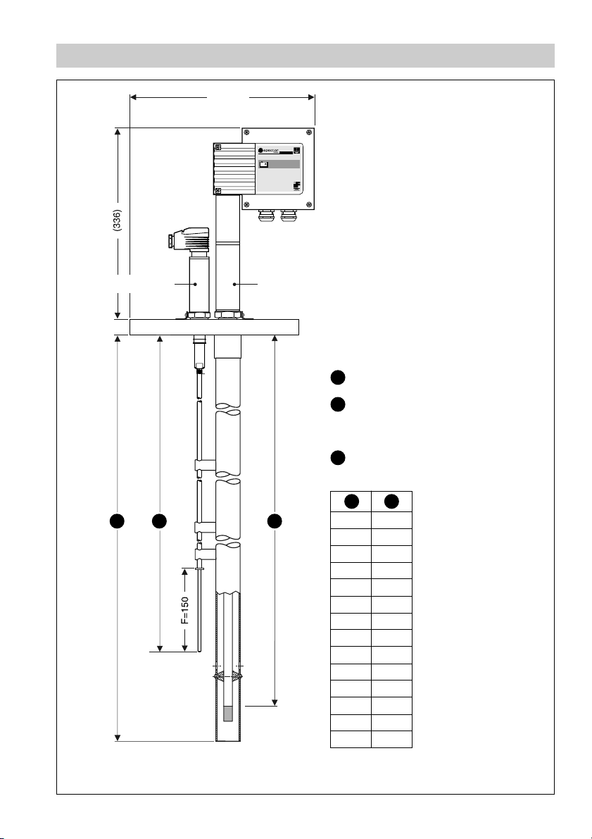
Dimensions
(330.5)
Fig. 1
NRG 16-11
1 2
3
NRGT 26-1
NRG 16-38S
NRGT 26-1
1
Max. length of installation
at 238 °C
2
Measuring range
NRG 16-11
3
Range for low water level
1 2
358
300
462
400
568
1095
1199
1304
1408
1513
1621
2141
673
779
884
989
500
600
700
800
900
1000
1100
1200
1300
1400
1500
2000
3
Page 4
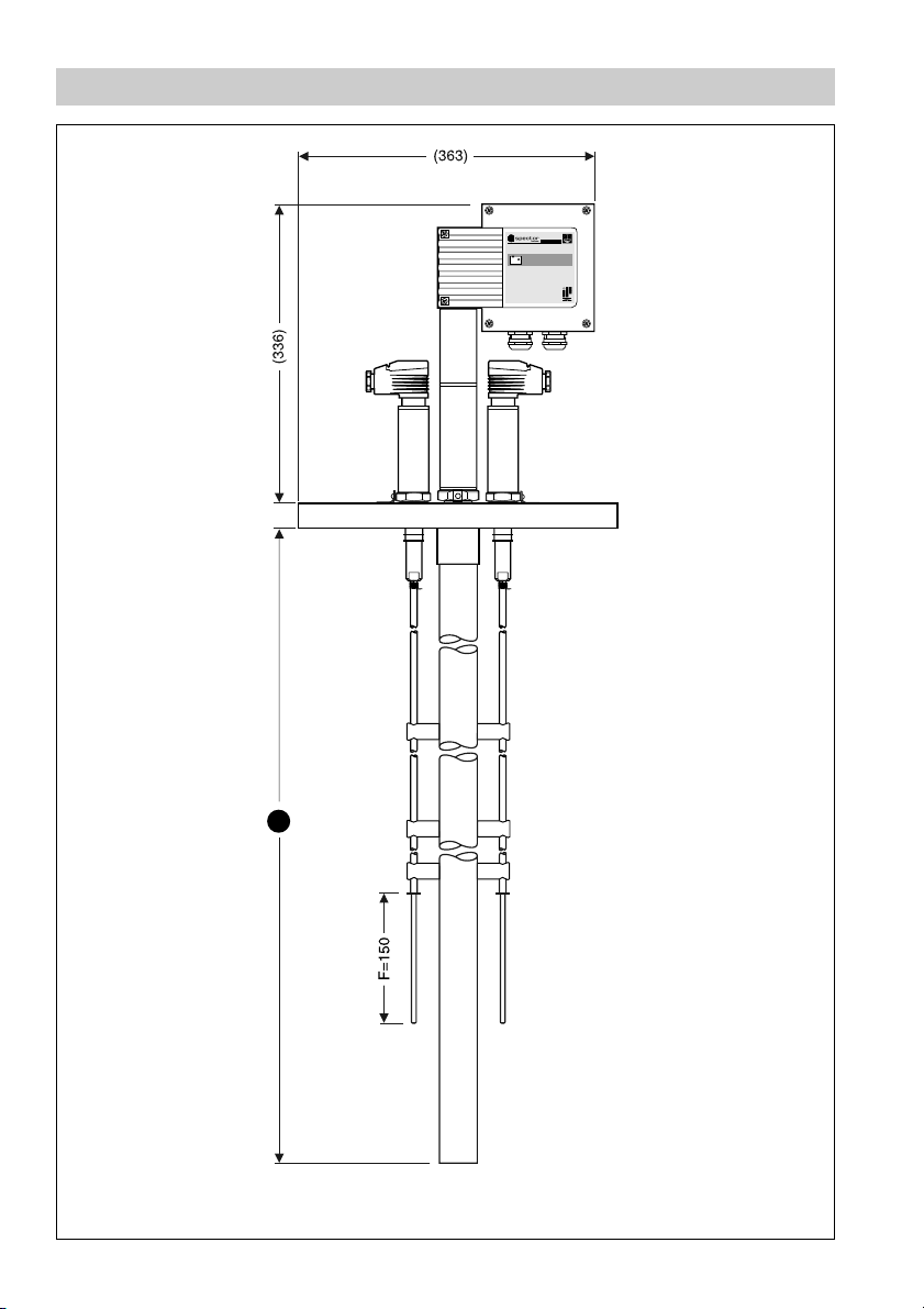
Dimensions
Fig. 2
4
1
NRG 16-39S
Page 5
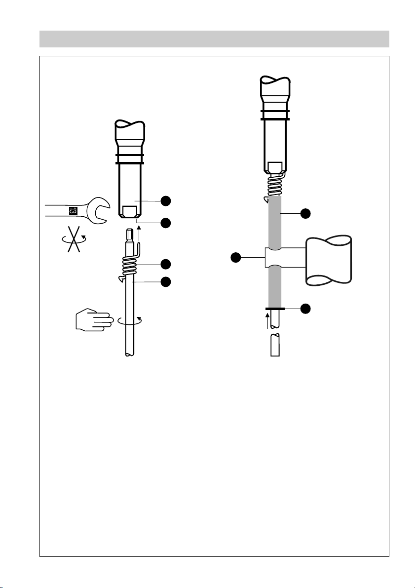
Parts Drawings
A
E
B
Fig. 3
C
D
U
F
Fig. 4
5
Page 6
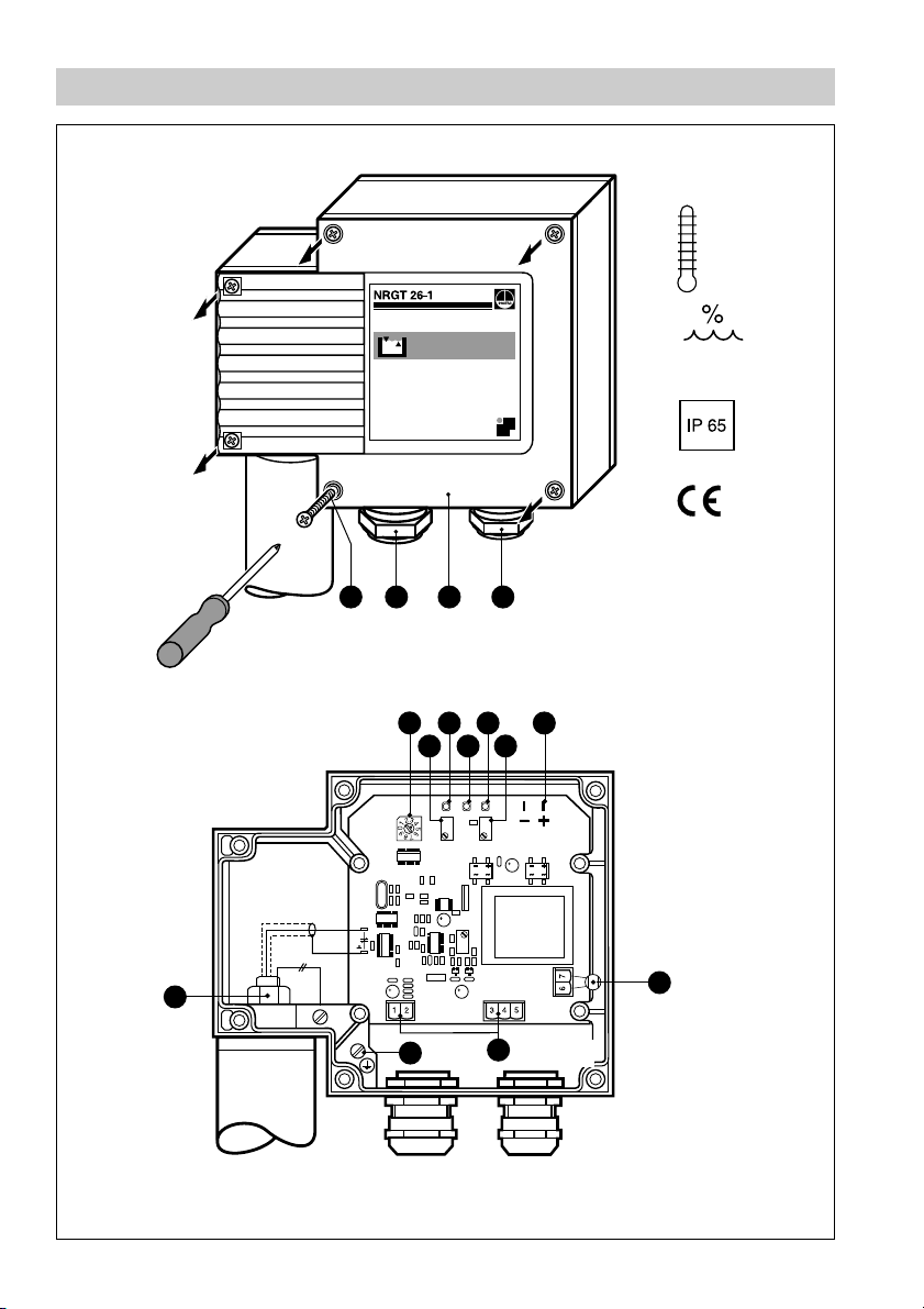
Parts Drawings
MAX 70°C
MAX 95%
Fig. 5
Fig. 6
G H
T
I
H
L NJ
MK
S
P
O
Q
R
6
Page 7
Key
A
Measuring electrode
B
Bore
C
Spring
D
Electrode tip
E
PTFE insulating tube
F
STARLOCK
G
Housing screws M4
H
Cable gland M 16 (PG 9), M 20 (PG 16)
I
Housing cover
J
Switch for measuring range
K
Potentiometer for lower measuring point (4 mA)
L
LED “Liquid level 0 %”
M
LED “Liquid level greater than 0 %, less than 100 %”
N
LED “Liquid level 100 %”
O
Potentiometer for upper measuring point
P
Terminal lugs for voltage measurement
Q
Thermal fuse T
R
Terminal strips
S
PE connection
T
Fixing nut
®
retaining ring
102 °C
max
U
Spacer disc
7
Page 8
Important Notes
Usage for the intended purpose
Use level electrodes type NRG 16-38 S, NRG 16-39 S only in conjunction with
controller type NRS 1-7 for high-liquid level limiting (M
AX. level alarm) and level
monitoring in marine steam boilers and (pressurized) hot water installations.
Safety Note
The equipment must only be installed by qualified staff.
Qualified staff are those persons who – through adequate training in electrical
engineering, the use and application of safety equipment in accordance with
regulations concerning electrical safety systems, and first aid & accident
prevention – have achieved a recognised level of competence appropriate to the
installation and commissioning of this device.
Danger
When loosening the electrode steam or hot water might escape.
This presents the danger of severe injuries to the whole body. It is
therefore essential not to remove the electrode unless the boiler pressure
is verified to be zero.
The electrode is hot during operation.
This presents the danger of severe burns to hands and arms.
Installation and maintenance work should only be carried out when the
system is cold.
Classification pursuant to article 1 PED*)
Category none
Designation Safety accessory
CE marking no
*) PED = Pressure Equipment Directive
8
Page 9

Explanatory Notes
Scope of Supply
NRG 16-38S
1 Level electrode type NRG 16-38 S
1 Terminal box for level transmitter
1 Installation manual
NRG 16-39S
1 Level electrode type NRG 16-39 S
1 Terminal box for level transmitter
1 Installation manual
Description
Water-level limiter with
electrode type NRG 16-38 S
The controller NRS 1-7 is to be used in conjunction with one level electrode
NRG 16-11 and designed as a self-monitoring water-level limiter featuring
periodic self-checking (SMART) and automatic monitoring of the output relay
contacts. The controller has the following function:
■ Low-level alarm with one switchpoint
The equipment combination detects the min. admissible liquid level (low-level
limiter).
Application in marine steam boilers and (pressurized) hot water installations.
The level transmitter integrated in the level electrode NRGT 26-1 enables
continuous level monitoring.
Water-level limiter with
electrode type NRG 16-39 S
The controller NRS 1-7 is to be used in conjunction with two level electrodes
NRG 16-11 and designed as a self-monitoring water-level limiter featuring periodic
self-checking (SMART) and automatic monitoring of the output relay contacts. The
controller has the following function:
■ Low-level alarm with one switchpoint
The equipment combination detects the min. admissible liquid level (low-level
limiter).
Application in marine steam boilers and (pressurized) hot water installations.
The level transmitter integrated in the level electrode NRGT 26-1 enables
continuous level monitoring.
one level electrode, level monitoring with one level
two level electrodes, level monitoring with one level
9
Page 10

Explanatory Notes – continued –
Function
Water level limiter NRG 16-11
The conductivity of the liquid is used to signal the liquid level. Some liquids are
conductive, which means that they allow an electric current to flow through them.
For the safe functioning of this device a minimum conductivity of the liquid to be
monitored is required (at least 10 µS/ cm at 25°C).
The relay de-energizing delay is 15 sec.
Level monitoring NRGT 26-1
The principle of capacitance measurement is applied to determine the liquid level.
The electrode rod and the vessel wall form a capacitor. If the level of the dielectric
located between the two capacitor plates changes, the current which flows through
the plates changes proportionally to the level. A dielectric is defined as an insulating
substance, which excludes many liquids such as water. In order to receive a useful
measuring result the measuring rod, which is completely submerged in the liquid,
must be completely insulated. After calibrating the zero point/measuring range
(0%/100%) of the electronic control unit, the level can be read off from a remote
display unit. The level measuring range (control range) can be changed during
operation.
System components
NRS 1-7
Control unit for low-level sensing electrode NRG 16-11 (MIN alarm) designed to use
in conjunction with level electrodes NRG 16-38 S and 16-39 S.
Function: Signalling of low-level alarm
Designs
■ NRG 16-38 S
1 Level electrode NRG 16-11
1 STARLOCK
®
retaining ring 11.5/4.8
1 Level electrode NRGT 26-1
Both level electrodes are installed together in one flange DN 100, Fig. 1
■ NRG 16-39 S
2 Level electrodes NRG 16-11
2 STARLOCK
®
retaining rings 11.5/4.8
1 Level electrode NRGT 26-1
All level electrodes are installed in one flange DN 150, Fig. 2
STARLOCK® is a registered trademark of Gebr. Titgemeyer GmbH & Co. KG, Osnabrück
10
Page 11

Explanatory Notes – continued –
Technical Data
Type Approval
GL 40 601-01 HH
LR 01/20026
ABS 01-HG 227959-PDA
BV 11400 / A1 BV
DNV A-8394
KR HMB 06190-MS 001
NK A 557 / 02 A 013
Service pressure
32 barg at 238 °C
Connection
NRG 16-38 S: Flanged DN 100, PN 40, DIN 2635
NRG 16-39 S: Flanged DN 150, PN 40, DIN 2635
Materials
Flange: 1.0460
Protection tube NRGT 26-1: 1.0460
Measuring electrode NRG 16-11: 1.4401
Spacer disc NRG 16-11: PEEK
Centering piece NRGT 26-1: PTFE
Lengths supplied
400 mm
1000 mm
1500 mm
2000 mm
Wiring
NRG 16-11: Four-pole connector with screw-type terminals und cable clamp,
NRGT 26-1: 2 and 3pole screw-type terminal strips,
Cell constant
NRG 16-11: C = 0.3 cm
Power consumption
NRGT 26-1: 5 VA
Mains voltage
NRGT 26-1: 230 V +/– 10 %, 50/60 Hz
Fuse
NRGT 26-1: Thermal fuse, T
Power consumption
NRGT 26-1: 5 VA
cable gland M 16 (PG 11).
cable gland with cable clamp M 16 (PG 11), M 20 (PG 16)
-1
115 V +/– 10 %, 50/60 Hz (optional)
24 V +/– 10 %, 50/60 Hz (optional)
= 102°C
max
11
Page 12

Explanatory Notes – continued –
Technical Data – continued –
Outputs
NRGT 26-1: Current output 4 – 20 mA
level-proportional, volt-free, load 500 ohm
Response time of level changes
NRGT 26-1: below 5 sec.
Sensitivity
NRG 16-11: from 10 µS/cm at 25°C
Indicators and adjustors
NRGT 26-1: 2 red LEDs “Liquid level 0 % – 100 %”,
1 green LED “Liquid level between 0 % and 100 %”,
1 code switch
2 adjustable resistors
Max. admissible ambient temperature
70 °C
Protection
IP 65 to DIN 40050
Approx. weight
NRG 16-38 S: 17 kg
NRG 16-39 S: 25.5 kg
12
Page 13

Explanatory Notes – continued –
Corrosion Resistance
When used for its intended purpose the safe functionting of the equipment will not be
impaired by corrosion.
Sizing
The electrode body must not be subjected to sharp increases in pressure. Welds and
flanges of the electrode are designed to withstand dynamic loading (bending and
alternating stress). The dimensional allowances for corrosion reflect the latest state
of technology.
Name Plate / Marking
Designation of the
equipment
Fig. 7
NRGT 26-1 S
13
Page 14

Explanatory Notes – continued –
Corrosion Resistance – continued –
Designation of the equipment
Fig. 8
NRG 16-11
Fig. 9
Designation of the
equipment
NRG 16-38S, NRG 16-39S
14
Page 15

Installation
NRG 16-38S, NRG 16-39S (Limiter NRG 16-11) – step 1
1. Mark low water level on electrode tip and slide locking spring out of the small
B
hole of the measuring electrode . Also mark the low water level and the level
150 mm above low water level on the protection tube of the level transmitter.
D
A
F
C
Fig. 3 and 4
2. Unscrew electrode tip from measuring electrode and remove the locking
spring . Push electrode tip through spacer disc , remove retaining ring
C U
and cut the electrode tip to length.
3. The electrode tip features a PTFE sleeve to provide sufficient creepage
D
D
D
D
distance and clearance. Strip off 150 mm of PTFE insulation (dimension ) from
A
F
F
the lower end of the electrode tip. Take new retaining ring from terminal box and
slide it along the lower end of the electrode tip . Make sure that 20 mm of the
D
upper end of the electrode tip (where the spring is located) remain uninsulated.
4. If a spacer disc is mounted near dimension you have to detach the spacer
U
disc from the protection tube of the level transmitter. Then slide the spacer disc
F
U
upwards and screw it into the nearest suitable M4 hole of the protection tube. In
order to prevent the electrode tip from swinging, the protection tube of the level
D
transmitter is provided with M4 holes every 100 mm starting at 350 mm so that the
spacer discs can be attached.
5. Push the electrode tip through the spacer discs , slide spring onto
electrode tip and screw back the electrode tip into the measuring electrode
and tighten. Use 13 mm open-end spanner to hold the measuring electrode .
Slide spring along electrode tip so that its end completely enters the small hole
B
.
6. If the electrode tips of the level electrode NRG 16-39 S are longer than the
protection tube of the level transmitter (dimension > ) slide the spacer discs
U
D
C
D
U
D
3 2
C
A
A
onto the tips at equal distances. Note that spacer discs must cover the PTFE area
and not the exposed metal rod.
NRG 16-38S, NRG 16-39S – step 2
1. Check seating surfaces and place joint ring onto mounting flange
(connecting standpipe).
2. Put combination electrode onto the mounting flange and tighten bolts in
diagonally opposite pairs.
Attention
■ Handle electrode with care. Do not bend electrode tip when mounting
and avoid subjecting the electrode to mechanical shocks.
■ Do not lag electrode body and transmitter housing above the mounting
flange.
■ Install level electrode only in a vertical position.
■ For the installation of the electrode a protection tube must be provided
on site, see installation specification page 22, 23.
15
Page 16

Installation – continued –
Installing Terminal Box of Level Transmitter NRGT 26-1, step 3
1. Unscrew fixing nut of the electrode in the level transmitter, Fig. 5 and 6.
2. Undo cover screws (cross recess M4) of the terminal box and remove cover .
T
G
I
The arrow on the name plate points towards the cover.
3. Unscrew fixing screws from cover plate and remove plate.
4. Pull all electrode cables through the hole for the fixing screw in the terminal box.
5. Put terminal box onto electrode and rotate it until the cable outlet points in the
required direction. Make sure that the gasket between electrode and terminal box
fits properly.
6. Pull all electrode cables through the fixing nut . Fasten fixing nut with a torque
T
of 30 Nm.
7. Connect electrode cables to terminal lugs (electronic insert, functional earth)
according to wiring diagram.
8. Screw back cover plate.
Please Note
■ For the approval of the boiler standpipe the relevant regulations must
be considered.
■ Refer to pages 22, 23 for typical installation examples.
Tools
■ Hacksaw
■ Flat file, medium cut
■ Open-end spanner 13 mm A. F.
■ Open-end spanner 17 mm A. F.
■ Open-end spanner 18 (19) mm A. F.
16
Page 17

Wiring
NRG 16-11
Note that screened four-core cable, e. g. I-Y(St)Y 2 x 2 x 0.8 or LIYCY 4 x 0.5 mm²
is required for wiring the electrode.
Max. cable length 100 m with conductivities from 10 µS/cm.
Max. cable length 30 m with conductivities from 0.5 µS/cm.
Wiring Diagram
Mains
Burner protection
circuit
Fig. 10
Attention
■
Fuse supply cables 250 mA (slow-blow).
Tools
■ Screwdriver for slotted screws, size 2.5, completely insulated to DIN VDE 0680-1
17
Page 18

Wiring – continued –
NRGT 26-1
1. Use flexible cable to connect the power supply. Use a separate flexible screened
cable, min. conductor size 1.5 mm² for connecting the signal output.
2. Undo screws and remove housing cover . The arrow on the name plate points
towards the cover, fig. 5.
3. Remove terminal strip from circuit board.
4. Undo union nuts of the cable gland and pull connecting cables for power supply
and signal output through separate cable glands.
5. Connect terminal strips and PE connection according to wiring diagram. Make
sure that the screen of the signal cable is also clamped under the earthing screw
for the PE connection.
6. Plug in terminal strip. Attention! The following displacements of base-insulated
cables are not allowed: power cables in low voltage area; signal cables in mains
voltage area.
7. Retighten union nuts of cable gland . Use plug supplied with electrode to seal
unused cable glands.
8. Configure level electrode (see “Basic Settings”, “Commissioning”).
9. Replace housing cover and fix it with screws , making sure that the cover
gasket fits properly.
Wiring Diagram
G I
R
H
H
I
S
G
Thermal fuse
Mains
Fig. 11
max. load
Earthing screw
in housing
Attention
■ Fuse supply cables 250 mA (slow-blow).
Tools
■ Screwdriver for cross head screws, size 1
■ Screwdriver for slotted screws, size 2.5, completely insulated according to
VDE 0680-1
18
Page 19

Basic Settings
Factory Settings NRGT 26-1
The compact system features the following factory set default values:
■ Measuring range 1275 mm: Switch position 4, water ≥ 20
■ Measuring range 1375 mm to 675 mm: Switch position 4, water ≥ 20
■ Measuring range 1775 mm to 1475 mm: Switch position 4, water ≥ 20
■ Measuring range 1575 mm to 1975 mm: Switch position 5, water ≥ 20
Establishing active measuring range
J
J
J
J
µ
µ
µ
µ
S/cm
S/cm
S/cm
S/cm
A control range can be established within the measuring range of the electrode.
Use switch to select the length of the active measuring range (control range),
J
Fig. 7
1
1
Active measuring range (control range)
2
Max. measuring range at 25 °C
3
Water, conductivity
4
Water, conductvity
5
Fuel oil EL, dielectric constant ε
>
20 µS/cm
>
5 µS/cm
37
r
J
2
Fig. 12
26
2.3
1
Lower
measuring
point
100
200
300
400
500
600
700
800
900
1000
1100
1200
1300
1400
1500
1600
1700
1800
1900
2000
3 4 5
4
3
4
3
4
3
4
4
4
4
4
4
4
4
4
4
4
5
4
5
4
5
4
5
4
5
4
5
4
5
5
5
5
6
5
6
5
6
5
6
3
3
3
3
3
3
3
3
3
3
3
3
3
3
3
3
3
4
4
4
Attention
1 2 J
If is clearly smaller than set switch one step back.
19
Page 20

Commissioning
Danger
The terminal strips and the electronic components of the NRGT 26-1 are
live during operation. This presents the danger of electric shock.
Use only a completely insulated screwdriver according to VDE 0680 for
setting the measuring points.
Check wiring
1. Make sure that the level electrodes NRG 16-11 and NRGT 26-1 are properly
connected according to the wiring diagram, Fig. 10, Fig. 11
2. Check whether the mains voltage corresponds to the voltage rating indicated on
the name plate.
Apply mains voltage
1. Apply power. The LED of the electrode NRGT 26-1 lights up (exposed
condition), Fig. 6
Adjusting lower measuring point NRGT 26-1
1. Fill boiler or vessel with liquid until the lower measuring point is reached.
2. Raise the pressure in the steam boiler or tank until the service pressure is reached.
3. Turn potentiometer to the left until the red LED lights up.
4. Turn potentiometer to the right until only the green LED lights up.
The lower measuring point is now adjusted.
L
K
K
L
M
Adjusting upper measuring point NRGT 26-1
1. Fill boiler or vessel with liquid until the upper measuring point is reached.
2. Turn potentiometer to the right until only the red LED lights up.
3. Turn potentiometer to the left until the green LED lights up.
4. Turn potentiometer to the right until the green LED goes out.
O
O
O
N
M
M
The upper measuring point is now adjusted.
5. Attach housing cover .
I
Note
When adjusting the measuring points of the electrode in a cold liquid,
the measuring points will shift with rising temperature as a result of the
longitudinal expansion of the electrode rod. Be sure to correct the
settings accordingly.
If a higher accuracy (for 0 % = 4 mA and 100 % = 20 mA) than ± 0.5 is
required, measure the level-proportional current at terminals 1 (–) and
2 (+) in order to establish more accurate settings.
20
Page 21

Operation
NRG 16-38S, NRG 16-39S
Designed for use in conjunction with controller NRS 1-7. Application in marine steam
boilers and (pressurized) hot water installations in accordance with type approval
requirements demanded by the corresponding classification societies.
Note
■ Refer to section “Malfunctions” on page 21 to analyse and eliminate
faults and malfunctions.
21
Page 22

Malfunctions
Warning
The terminal strip of the NRGT 26-1 is live during operation. This presents
the danger of electric shock.
Cut off power supply before fixing or removing the housing cover.
Fault finding list for troubleshooting
The equipment fails to work
Fault:
Remedy:
Mains voltage has not been applied.
Apply mains voltage. Wire equipment according to wiring diagram.
Fault:
Remedy:
The thermal fuse of the NRGT 26-1 has been activated.
In case of a defective thermal fuse the mains voltage is not applied
across terminal . Replace thermal fuse.
Q
Stock code 051629
The ambient temperature must not exceed 70°C.
Fault:
Remedy:
Fault:
Remedy:
The printed circuit board of the NRGT 26-1 is defective.
Replace printed circuit board. Stock code 391360
The internal joint ring of the electrode rod of the NRG 16-11 is damaged.
Replace level electrode NRG 16-38 S / NRG 16-39 S.
The equipment does not work accurately
Fault:
Remedy:
Fault:
Remedy:
Incorrect setting of the measuring range.
Adjust switch properly, see “Basic Settings”.
J
Dirt deposits have accumulated on the electrode rod.
Replace level electrode NRG 16-38 S / NRG 16-29 S.
If faults occur that are not listed above, please contact our subsidiary or agency in
your country.
22
Page 23

Example of Installation
1
2
3
Fig. 13
4
Key
Flange PN 40, DN 100,
1
DIN 2527 (NRG 16-38S)
Flange PN 40, DN 150,
DIN 2527 (NRG 16-39S)
2
For the approval of the boiler
standpipe with connecting
flange the relevant regulations
must be considered.
3
Vent hole
Protection tube
4
DN 100, DN 150
∅ = 20 mm
23
Page 24

GESTRA Gesellschaften · GESTRA Companies · Sociétés GESTRA · Sociedades Gestra · Società GESTRA
Vertretungen weltweit · Agencies all over the world · Représentations dans le monde entier · Representaciones en todo el mundo · Agenzie in tutto il mondo
Großbritannien
Flowserve Flow Control (UK) Ltd.
Burrel Road, Haywards Heath
West Sussex RH 16 1TL
Tel. 00 44 14 44 / 31 44 00
Fax 00 44 14 44 / 31 45 40
E-mail: sales@flowserve.com
France
Flowserve Flow Control S.A.S.
10 Avenue du Centaure, BP 8263
F-95801 CERGY PONTOISE CEDEX
Tél. 0 03 31 /34 432660
Fax 00331/34432687
E-mail: gnation@flowserve.com
España
GESTRA ESPAÑOLA S.A.
Luis Cabrera, 86-88
E-28002 Madrid
Tel. 0034 91 / 5152 032
Fax 003491/4136747; 5152036
E-mail: gestra@gestra.es
Italia
Flowserve S.p. A
Divisione Italgestra
Via Prealpi, 30 – 20032 Cormano (MI)
Tel. 00 3902/ 66 3251
Fax003902/6151863
E-mail: info@italgestra.it
Portugal
Flowserve Portuguesa, Lda.
Av. Dr. Antunes Guimarães, 1159
Porto 4100-082
Tel. 0035122/6198770
Fax 00351 22/ 61075 75
E-mail: gestra@gestra.pt
®
GESTRA GmbH
Postfach 10 54 60, D-28054 Bremen, Münchener Str. 77, D-28215 Bremen
Telefon +49 (0) 421 35 03 -0, Telefax +49 (0) 421 35 03 - 393
E-Mail gestra.gmbh@flowserve.com, Internet www.gestra.de
A Unit of Flowserve Corporation
810746-00/303cs · © 2002 GESTRA GmbH · Bremen · Printed in Germany
24
 Loading...