

Page 1

GESTRA
GESTRA Steam Systems
NRG 111-11
Installation Instructions 810898-01
Level Electrode
NRG 111-11
1
Page 2

Contents
Page
Important Notes
Usage for the intended purpose .............................................................................................................. 4
Safety note ............................................................................................................................................. 4
Danger ................................................................................................................................................... 4
Classification pursuant to article 1 of the Pressure Equipment Directive (PED) ........................................ 4
Explanatory Notes
Scope of supply...................................................................................................................................... 4
Description............................................................................................................................................. 5
Function ................................................................................................................................................. 5
System components ............................................................................................................................... 5
Design ................................................................................................................................................... 5
Technical Data
NRG 111-11 ........................................................................................................................................... 6
Corrosion resistance .............................................................................................................................. 7
Sizing ..................................................................................................................................................... 7
Name plate /marking ............................................................................................................................. 7
Dimensions ............................................................................................................................................ 8
Design
NRG 111-11 ........................................................................................................................................... 9
Key ...................................................................................................................................................... 11
Functional Elements
NRG 111-11 ......................................................................................................................................... 10
Key ...................................................................................................................................................... 11
Installation
NRG 111-11, step 1 ............................................................................................................................. 12
NRG 111-11, step 2 ............................................................................................................................. 12
Tools .................................................................................................................................................... 13
Examples of installation ....................................................................................................................... 14
Key ...................................................................................................................................................... 15
Wiring
NRG 111-11 ......................................................................................................................................... 15
Wiring diagram .................................................................................................................................... 16
Voltage table ........................................................................................................................................ 17
Tools .................................................................................................................................................... 17
2
Page 3

Contents – continued –
Page
Commissioning
Check wiring ........................................................................................................................................ 17
Apply mains voltage ............................................................................................................................. 17
Operation
Water level limiter ................................................................................................................................ 18
Operation Malfunctions
Fault finding list for troubleshooting ..................................................................................................... 18
Annex
Declaration of Conformity ..................................................................................................................... 19
3
Page 4
Important Notes
Usage for the intended purpose
Use level electrode type NRG 111-11 only in conjunction with NRS 1-7 as water level limiter
(low level alarm). The equipment must not be used in explosion risk areas.
Safety Note
The equipment must only be installed and commissioned by qualified and adequately trained
personnel.
Maintenance and retrofitting must only be performed by entrusted personnel who – through adequate
training – have achieved a recognized level of competence.
Danger
When loosening the electrode steam or hot water might escape. This presents the danger
of severe scalding. It is therefore essential not to remove the electrode unless the boiler
pressure is verified to be 0 barg.
The electrode is hot during operation. This presents the danger of severe burns to hands
and arms. Installation and maintenance work should only be carried out when the system
is cold.
If the internal ceramic insulation breaks hot steam may escape through the lateral relief
vent of the electrode stem.
This presents the danger of severe scalding!
Do not stand close to the electrode during operation.
Classification pursuant to article 1 of the Pressure Equipment Directive (PED)
Category IV
Designation Safety accessory
CE marking CE 0525
Explanatory Notes
Scope of supply
NRG 111-11
1 Level electrode NRG 111-11
1 Gasket 33x 39 DIN 7603-1.4301
1 Sealing plug for M 20 connection
1 Surface extension disk with grub screw
1 Lock washer
1 Installation manual
4
Page 5

Explanatory Notes – continued –
Description
The level electrode NRG 111-11 detects the min. liquid level (low level alarm) in a steam boiler. The
operation of the electrode is based on the conducitivity measuring principle using the electrical
conductivity of water for signalling one liquid level:
■ Low level alarm (MIN alarm)
The NRG 111-11 is designed for use in conjunction with level switch NRS 1-7 as a self-monitoring low
level limiter with periodic self-checking (SMART) feature.
Application in steam and pressurised hot water plants in accordance with TRD 604, sheet 1 and sheet 2
(24h/72h operation) as well as EN 12952 and 12953.
The electrical equipment meets the requirements of the Regulations on Protection Circuits DIN VDE
0116 (prEN 501565-1).
Function
The water level limiter comprises the level electrode type NRG 111-11 and GESTRA level switch NRS
1-7. The level electrode NRG 111-11 consists of two concentrically arranged electrodes (measuring
electrode and compensating electrode) which are isolated from each other by special insulating
seals.
The level limiter operation is based on the conductive measuring principle using the electrical
conductivity of water for signalling water level. During normal, trouble-free operation the level
electrode tip is immersed in boiler water and no low level alarm is given. A low level alarm will only
be raised if the electrode tip is exposed for more than 3 seconds. A low level alarm will also be
activated if the insulating seals placed between the electrodes and the body are no longer pressure
tight, allowing water to penetrate into the cavities between the body, tube and stud. However in this
instance the alarm is caused by a malfunction of the electrode, and confirmation should always be
done by checking if there is water in the gauge glass. The equipment combination NRG 111-11 and
NRS 1-7 provides fail safe protection against a first fault in accordance with TRD 604.
If the internal ceramic insulation breaks steam and hot water may escape through the lateral relief
vent of the electrode stem.
System Components
NRS 1-7
Level switch NRS 1-7, 0.5 µS version. The limiter features a two channel circuit (redundancy) and an
automatic periodic self-checking routine in accordance with DIN VDE 0116 (prEN 50156-1).
Design
NRG 111-11:
Level electrode with screwed connection 1" BSP, ISO 228-1. Fig. 1
5
Page 6

Technical Data
NRG 111-11
Type approval no.
TÜV· WB· 01-354
EG 01 202 931-B-01-0077-01
Service pressure
NRG 111-11: 183 barg (at 357 °C)
Connection
1" BSP (to ISO 228-1)
Flange PN 320, DN 50, DIN 2501-1 (optional)
Flange PN 250, DN 80, DIN 2501-1 (optional)
Materials
Body 3.2161 G AlSi8Cu3
Stem 1.4529,
Measuring electrode
Electrode insulation: Special ceramic material
Lengths available
500 mm
1000 mm
1500 mm
2000 mm
2500 mm
3000 mm
pH value
Max. admissible: 10
Cell constant C
0.13 cm
Response sensitivity
0.5 µS/cm up to 400 µS/cm at 25 °C
Cable entry
Cable gland with integrated cable clamp
M 20 (2) (PG 16)
Protection
IP 65 to DIN EN 60529
Max. admissible ambient temperature
70 °C
Weight
Approx. 1.8 kg
X39CrMo17-1
1.4401,
X5CrNiMo17-12-2
-1
with measuring surface extension
6
Page 7

Technical Data – continued –
Corrosion Resistance
If the unit is used for the intended purpose, its safety is not impaired by corrosion.
Sizing
The housing must not be subjected to sharp increases in pressure. Welds and flanges are designed to
withstand dynamic loading (bending and alternative stress). The dimensional allowances for corrosion
reflect the latest state of technology.
Name Plate / Marking
Designation
Fig. 1
7
Page 8

Technical Data – continued –
Dimensions
175
140
≥ 185
500, 1000, 1500,
2000, 2500, 3000
400
b = 70
1" BSP, ISO 228-1
136
30
8
Fig. 2
Page 9
Design NRG 111-11
H
A
B
C
D
E
G
Fig. 3 Fig. 4
F
30
J
I
110
14
Fig. 5 Fig. 6
∅ 58
∅ 40
1" BSP, ISO 228-1
N8
N10
0.5
9
Page 10

Functional Elements
Fig. 7
MAX 70 °C
MAX 95 %
K L M L
10
P
Fig. 8
O
N
Page 11

Key
Electrode rod
A
Bore
B
Spring
C
Electrode tip
D
Disk (measuring surface extension)
E
Retaining ring
F
Grub screw
G
Gasket D 33x 39 DIN 7603-1.4301
H
Seating surface
I
Electrode thread
J
Housing screws M 4
K
Cable entry M 20x1.5
L
Housing cover
M
Terminal strip
N
PE connection
O
Plug
P
11
Page 12

Installation
NRG 111-11, step 1
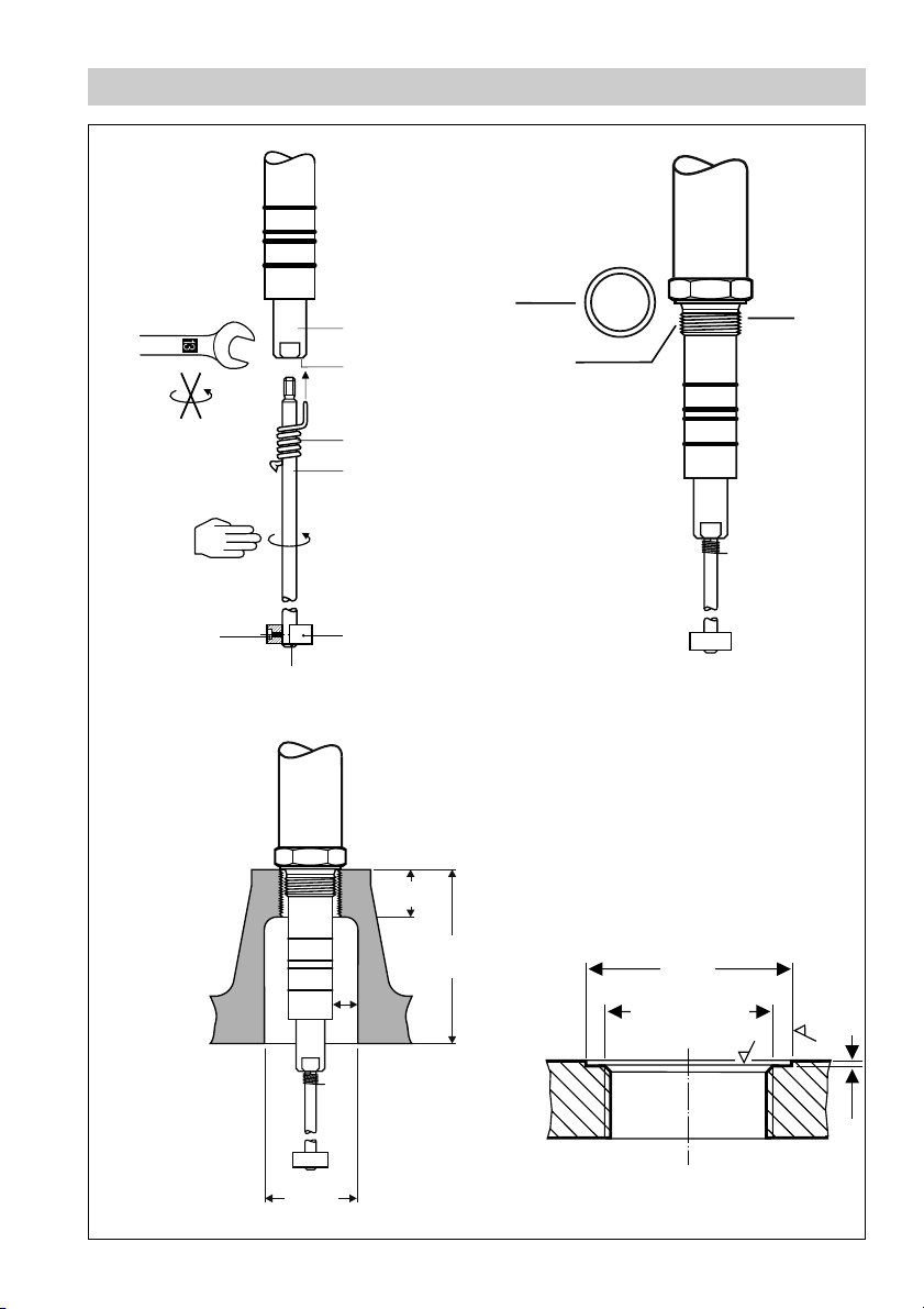
1. Screw electrode tip D into measuring electrode A. Fig. 3
2. Carefully determine required measuring length of electrode. Observe min. length, Fig. 2
3. Mark length of electrode tip D.
4. Unscrew electrode tip D from measuring electrode A and cut tip.
5. After visual inspection screw electrode tip D into measuring electrode A. Slide spring C along
electrode tip D, so that its bent end completely enters into small bore B.
6. Fit surface extension disk E to electrode tip end and make sure that electrode tip protrudes 2 mm
beyond the bottom of the surface extension disk. Fix the surface extension disk in this position with
the grub screw G. Push lock washer F over electrode tip end against surface extension disk E.
NRG 111-11, step 2
1. Check seating surfaces. Fig. 6
2. Place joint ring E onto seating surface F of electrode. Fig. 4
3. Apply a light smear of silicone grease G (e. g. Molykote
4. Screw level electrode into threads or flange provided on vesssel and tighten with a 41 mm open-end
spanner. The torque required is 475 Nm when cold.
Attention
■ The seating surfaces of the standpipe or the flange provided on the vessel must be
accurately machined, see fig. 6.
■ Do not bend electrode tip when mounting.
■ Use only ring joint (of stainless steel 1.4301) D 33x39 DIN 7603 supplied with the
electrode.
■ Do not lag electrode body above the hexgonal section.
■ Do not insulate electrode thread with hemp or PTFE tape.
■ The leakage path between electrode and flange (mass) must be at least 14 mm, fig. 5
■ Observe minimum distances and spacing dimensions when installing the electrode,
fig. 5
®
111) to electrode thread.
Molykote® 111 is a registered trademark of DOW Corning Corp., Midland Michigan, USA
12
Page 13

Installation – continued –
Note
■ For the approval of the boiler standpipe the relevant regulations
must be considered.
■ Refer to page 14 for four typical installation examples.
■ The inclination angle of the electrode must not exceed 45°. The max. length of the
electrode rod is 1600 mm.
Tools
■ Open-end spanner 13 mm A. F.
■ Open-end spanner 41 mm A. F.
■ Hacksaw
■ Flat file, medium cut
13
Page 14

Examples of Installation
1" BSP
DN 50
∅ 20
4
1
2
3
20
5
7
8
Fig. 9 Fig. 10
≤ 90°
∅ 20
≥10
9
0
1
1
Centre distance
1" BSP
DN 80
1
14
Fig. 11
1
Page 15

Key
Flange PN 320, DN 50, DIN 2505-1
1
Flange PN 250, DN 80, DIN 2505-1
For the approval of the boiler standpipe with connecting flange the relevant regulations must be
2
considered.
Vent hole Provide vent hole as close to the boiler wall as possible!
3
High water (HW)
4
Electrode rod d = 8 mm
5
Protection tube DN 100
7
Electrode distance ≥ 14 mm
8
Low water (LW)
9
Reducer DIN 2616-2, K-88.9 x 3.2- 42.4x 2.6 W
0
Wiring
NRG 111-11
2
Note that screened four-core cable, e. g. I-Y(St)Y 2 x 2 x 0.8 or LIYCY 4 x 0.5 mm
to the electrode.
Max. cable length 30 m with water conductivity from 0.5 µS/cm.
Max. cable length 15 m with water conductivity from 0.5 µS/cm when used in conjunction with inverter
URN 1 (24 d. c.).
1. Undo screws K and remove housing cover M. Fig. 7
2. Unscrew union nuts of cable entry L.
3. Slacken plug P with 18 mm open-end spanner but do not remove, fig. 8
The electrode terminal box can now be turned through +/–180°.
4. Turn electrode terminal box into desired position (+/–180°).
5. Tighten plug P slightly.
6. Remove terminal strip N from board.
7. Connect terminal strip according to wiring diagram.
8. Affix terminal strip.
9. Re-attach housing cover M and fix it with screws K.
is required for wiring
15
Page 16
Wiring – continued –
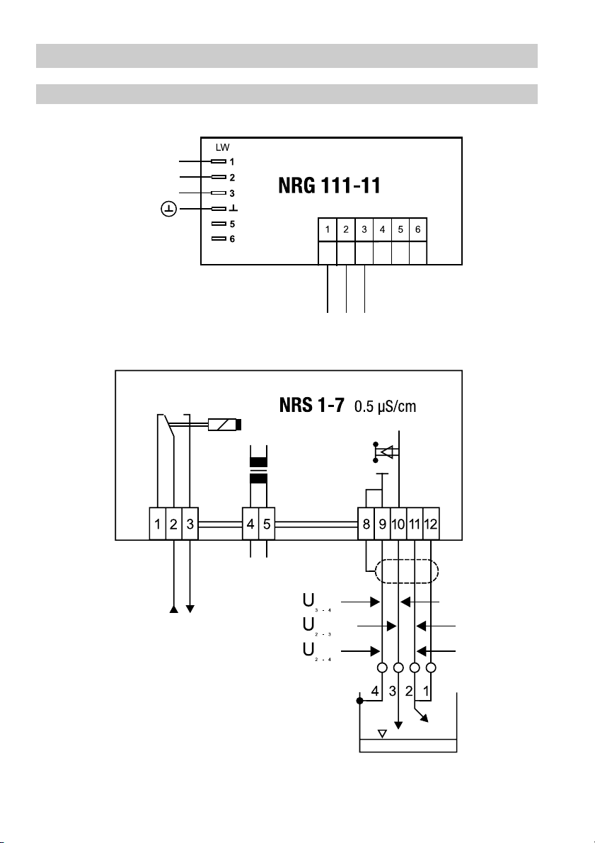
Wiring Diagram
Compensation electrode
Compensation electrode
Measuring electrode
Fig. 12
16
Page 17
Wiring – continued –
Attention
■ Use sealing plug for cable entry L if only one cable runs to the terminal box.
Insert sealing plug supplied with the electrode (IP 65)!
Voltage table
Use this voltage table to check whether the level electrode is submerged or if there is a malfunction.
Observe the wiring diagram of the NRS 1-7, fig. 12
U
10 V
eff
C=0.13 cm
1-2
0.5 µS/cm,
-1
U
1-4
submerged exposed
U
1-2
<
2
U
1-2
≥
2
malfunction (submerged / alarm)
U
2-4
≤
U
1-4
Note
■
The self-checking routine of the amplifier NRS 1-7 reduces U
to 0 volt!
every 40 sec.
1-2
Tools
■ Screwdriver for cross head screws, size 1
■ Screwdriver for slotted screws, size 2.5, completely insulated according to DIN VDE 0680-1
■ Open-end spanner 18 (19) mm A. F.
Commissioning
Check wiring
Make sure that the electrode NRG 111-11 is connected to the level switch NRS 1-7 according to the
wiring diagram. Fig. 12
Apply mains voltage
Apply mains voltage to level switch NRS 1-7.
17
Page 18

Operation
Water level limiter
Application in conjunction with level switch NRS 1-7 in steam and pressurised hot water plants in
accordance with TRD 401, TRD 602, TRD 604, EN 12952, EN 12953 or according to other national
regulations.
Note
■
To analyse and eliminate malfunctions use “Fault finding list for troubleshooting” on
page 18!
Operation Malfunctions
Fault finding list for troubleshooting
Level electrode immersed – low level alarm
Fault: Mains voltage not applied.
Remedy: Apply mains voltage. Connect electrode according to wiring diagram.
Fault: The electrode body does not have earth connection to the boiler.
Remedy: Clean seating surfaces and insert metal joint ring (of stainless steel 1.4301)
D 33 x 39 to DIN 7603.
Do not insulate level electrode with hemp or PTFE tape!
Fault: The internal insulation of the electrode rod is damaged.
Remedy: Replace level electrode.
Level below “low level limit” – no function
Fault: The electrode rods have earth contact.
Remedy: Check and change installation position if necessary.
Fault: The vent hole in the protection tube does not exist, is obstructed or flooded.
Remedy: Check protection tube and, if necessary, provide vent hole.
Fault: The isolating valves of the external measuring pot (optional extra) are closed.
Remedy: Open isolating valves.
If faults occur that are not listed above or cannot be corrected, please contact our service centre or
authorized agency in your country.
18
Page 19

Annex
Declaration of Conformity
We hereby declare that the equipment NRG 111-11 conforms to the following European guidelines:
■
LV guideline 73/23/eec version 93/68/eec
■
EMC guideline 89/336/eec version 93/68/eec
■
Pressure Equipment Directive (PED) No. 97/23/eec of 29 May 1997
The electrodes are safety accessories as defined in paragraph 1, section 2.1.3 PED.
Applied conformity assessment procedure: Annex III, Module B and D.
The guidelines and directives are based on the following harmonised standards:
■
LV standard DIN EN 50178
■
EMC standard DIN EN 50 081-2, DIN EN 61000-6-2
Other technical regulations applied: VdTÜV Bulletin “Wasserstand 100”
(= Water Level 100) 04.1990 and draft 08.2001.
This declaration is no longer valid if modifications are made to the equipment without consultation
with us.
Bremen, 10th October 2003
GESTRA AG
Dipl.-Ing. Stefan Bode
(Academically qualified engineer)
Head of R & D Dept. Electronics
Dipl.-Ing. Lars Bohl
(Academically qualified engineer)
Quality Assurance Manager
19
Page 20

Weltweite Vertretungen finden Sie unter:
www.gestra.de
GESTRA
España
GESTRA ESPAÑOLA S.A.
Luis Cabrera, 86-88
E-28002 Madrid
Tel. 00 34 91/ 51 52 032
Fax 0034 91/ 41 36 747; 51 52 036
E-mail: aromero@flowserve.com
Great Britain
Flowserve Flow Control (UK) Ltd.
Burrel Road, Haywards Heath
West Sussex RH 16 1TL
Tel. 00 44 14 44 / 31 44 00
Fax 00 44 14 44 / 31 45 57
E-mail: gestraukinfo@flowserve.com
Italia
Flowserve S.p.A.
Flow Control Division
Via Prealpi, 30
l-20032 Cormano (MI)
Tel. 00 39 02/ 66 32 51
Fax 0039 02/ 66 32 55 60
E-mail: infoitaly@flowserve.com
Poland
GESTRA POLONIA Spolka z.o.o.
Ul. Schuberta 104
PL - 80-172 Gdansk
Tel. 00 48 58 /306 10 -02 od 10
Fax 00 48 58 /306 33 00
E-mail: gestra@gestra.pl
Portugal
Flowserve Portuguesa, Lda.
Av. Dr. Antunes Guimarães, 1159
Porto 4100-082
Tel. 00351 22 /6 1987 70
Fax 0035122/6107575
E-mail: jtavares@flowserve.com
USA
Flowserve DALCO Steam Products
2601 Grassland Drive
Louisville, KY 40299
Tel.: 00 15 02 / 4 95 01 54, 4 95 17 88
Fax: 00 15 02 / 4 95 16 08
E-Mail: dgoodwin@flowserve.com
GESTRA AG
Postfach 10 54 60, D-28054 Bremen
Münchener Str. 77, D-28215 Bremen
Telefon +49 (0) 421 35 03- 0
Telefax +49 (0) 421 35 03- 393
E-Mail gestra.ag@flowserve.com
Internet www.gestra.de
810898-01/1004c · © 2003 GESTRA AG · Bremen · Printed in Germany
20
 Loading...