


Fisher & Paykel RDV3485GDN, RHV3484N, RDV3485GDL, FPRERADWRH3002, FPRERADWRH3003 Installation manual
...
PROFESSIONAL RANGE
RDV, RHV & RIV
models
INSTALLATION GUIDE
US CA
!
WARNING!
If the information in this manual
is not followed exactly, a fire or
explosion may result causing
property damage, personal injury
or death.
Do not store or use gasoline
or other flammable vapors and
liquids in the vicinity of this or any
otherappliance.
NEVER use this appliance as a
space heater to heat or warm
the room. Doing so may result in
carbon monoxide poisoning and
overheating of theappliance.
SAFETY AND WARNINGS
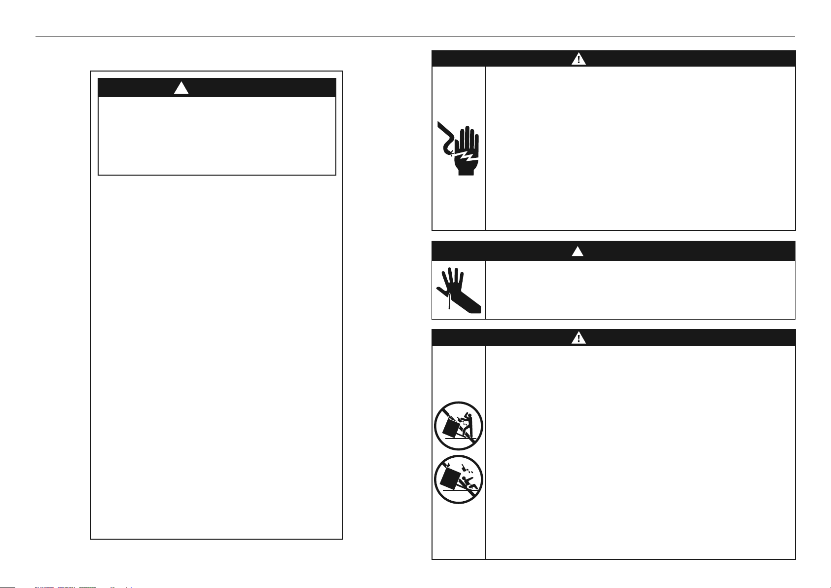
WARNING!
Electric Shock Hazard
Failure to follow this advice may result in
electrical shock or death.
• Before carrying out any work on the electrical
section of the appliance, it must be disconnected
from the mains electricitysupply.
• Connection to a good ground wiring system is
absolutely essential and mandatory.
• Alterations to the domestic wiring system must
only be made by a qualified electrician
!
WARNING!
Cut Hazard
Failure to use caution could result in injury.
• Take care: some edges are sharp.
What to Do if you Smell Gas
• Do not try to light any appliance.
• Do not touch any electrical switch.
• Do not use any phone in your building.
• Immediately call your gas supplier from
a neighbor’s phone. Follow the gas
supplier’s instructions.
• If you cannot reach your gas supplier,
call the fire department.
Installation and service must be
performed by a qualified installer,
service agency or the gas supplier.
2
Failure to follow this advice may result in
death or seriousburns to children of adults.
• To reduce the risk of tipping the appliance, the
appliance must be secured by properly installed
anti-tip device packed with the appliance.
• A child or adult can tip the range and be killed.
• Install the anti-tip device to the structure by
fastening the supplied bracket to the floor and
wall following the instructions for installing the
anti-tip device.
• Engage the anti-tip device.
• Re-engage the anti-tip device if the range
ismoved.
WARNING!

SAFETY AND WARNINGS
WARNING!
Extremely Heavy
Failure to follow this advice may result in
damage or personalinjury.
• Proper equipment and adequate manpower must
be used in moving the range to avoid personal
injury or damage to the unit or the floor. The unit
is heavy and rests on adjustable steellegs.
WARNING!
To avoid hazard, follow these instructions carefully before installing or using
thisappliance.
z
Please make this information available to the person installing the appliance–
doing so could reduce your installation costs.
z
Save these instructions for the local inspectors use.
z
This range is to be installed and connected to the electricity supply only by an
authorized person.
z
If the installation requires alterations to the domestic electrical system, call a
qualified electrician. The electrician should also check that the socket cable section
is suitable for the electricity drawn by the range.
z
Service should only be done by authorized technicians. Technicians must disconnect
the power supply before servicing this appliance.
z
The range must be grounded.
z
Installation must comply with your local building and electricity regulations.
z
This appliance must be installed and connected to the mains power supply only
by a suitably qualified person according to these installation instructions and
in compliance with any applicable local building and electricity regulations.
Failuretoinstall the appliance correctly could invalidate any warranty or
liability claims.
z
Ensure the installer shows the customer where the gas supply shut-off
valve is located.
z
If the power supply cable is damaged, it must be replaced by the manufacturer,
itsservice agent or similarly qualified person in order to avoid a hazard.
z
A circuit breaker is recommended.
z
Do not use adaptors, reducers or branching devices to connect the oven to
themainselectricity supply, as they can cause overheating and burning.
z
Improper installation, adjustment alteration, service or maintenance can
cause property damage, injury or death. Read the installation, operating and
maintenance instructions thoroughly before using, installing or servicing
this appliance.
z
A risk of the appliance tipping over exists if the appliance is not installed in
accordance with installation instructions.
z
DO NOT obstruct the flow of combustion or ventilation air to the appliance.
Besureafresh air supply is available.
z
California Proposition 65–The burning of gas cooking fuel generates some
by-products which are known by the State of California to cause cancer or
reproductive harm. California law requires businesses to warn customers of
potential exposure to such substances. To minimize exposure to these substances,
always operate this unit according to the manufacturer’s instructions and provide
good ventilation to the room when cooking with gas.
z
Check local building codes for the proper method of range installation.
Localcodesvary. Installation, electrical connections, and grounding must comply
with all applicable codes. In the absence of local codes, the range should be
installed in accordance with the latest edition of National Fuel Gas Code ANSI
Z223.1 and National Electrical Code ANSI/NFPA 70.
z
In Canada: Installation must be in accordance with the current CAN/CGA
B149.1&2 Gas Installation codes and/or local codes. Electrical installation must
be in accordance with the current CSA C22.1 Canadian Electrical Codes Part 1 and/
or local codes.
z
Be sure that the unit being installed is set up for the kind of gas being used.
The gasrange is shipped from the factory set and adjusted for Natural Gas or
LP (propane), depending on the specific model ordered. Verify that the range
is compatible with the gas at the installation site before proceeding further.
Returnrange to dealer if the unit is not set for site gas supply.
z
The appliance must not be installed behind a decorative door in order to
avoid overheating.
zz
Do not lift the range by the door handle. Doing so may damage the product.
zz
Before use, ensure all doors are correctly installed.
zz
Two persons are required to move the product safely to the installation location.
IMPORTANT!
SAVE THESE INSTRUCTIONS
The models shown in this installation guide may not be available in all markets and are subject to change at any time. For current details about model and specification availability in your country,
please go to our website www.fisherpaykel.com or contact your local Fisher&Paykel dealer.
3

PARTS SUPPLIED FOR INSTALLATION
Anti-tip bracket (1) 5/16" x 1 1/2"
#10 x 2"
wood screws (4)
sleeve anchors (2)
Lag bolts and
washers (2)
Foot cover
sets (2)
4

PRODUCT DIMENSIONS–30" MODELS
C
B
PLAN
H
I
C
F
G
A
J D
E
PROFILEFRONT
PRODUCT DIMENSIONS
A Overall height of range
(from floor to cook surface, excl. pan supports andvent trim)
30" MODELS
IN MM
min 35 3/4
max 36 3/4
min 908
max 933
B Overall width of range 29 7/8 759
C Overall depth of range (excl. handle and dials) 29 1/8 740
D Depth of chasis 25 3/8 644
E Depth from rear of chassis to front of control panel 27 11/16 703
F Height from top of cook surface to top of pan supports 1 9/16 40
G Height from top of cook surface to top of
zz
vent trim (as illustrated)
zz
angled vent trim (if fitted)
1 3/4
3 1/2
45
90
H Height from top of cook surface to bottom of chassis 35 1/4 895
I Adjustable feet height min 1/2
max 1 1/2
min 13
max 38
J Depth of open door to front control panel 19 1/8 486
5

PRODUCT DIMENSIONS–36" MODELS
C
B
PLAN
H
C
I
F
G
A
J D
E
PROFILEFRONT
PRODUCT DIMENSIONS
A Overall height of range
(from floor to cook surface, excl. pan supports andvent trim)
36" MODELS
IN MM
min 35 3/4
max 36 3/4
min 908
max 933
B Overall width of range 3 5 7/ 8 911
C Overall depth of range (excl. handle and dials) 29 1/8 740
D Depth of chassis 25 3/8 644
E Depth from rear of chassis to front of control panel 27 11/16 703
F Height from top of cook surface to top of pan supports 1 9/16 40
G Height from top of cook surface to top of
zz
vent trim (as illustrated)
zz
angled vent trim (if fitted)
1 3/4
3 1/2
45
90
H Height from top of cook surface to bottom of chassis 35 1/4 895
I Adjustable feet height min 1/2
max 1 1/2
min 13
max 38
J Depth of open door to front control panel 19 1/8 486
6
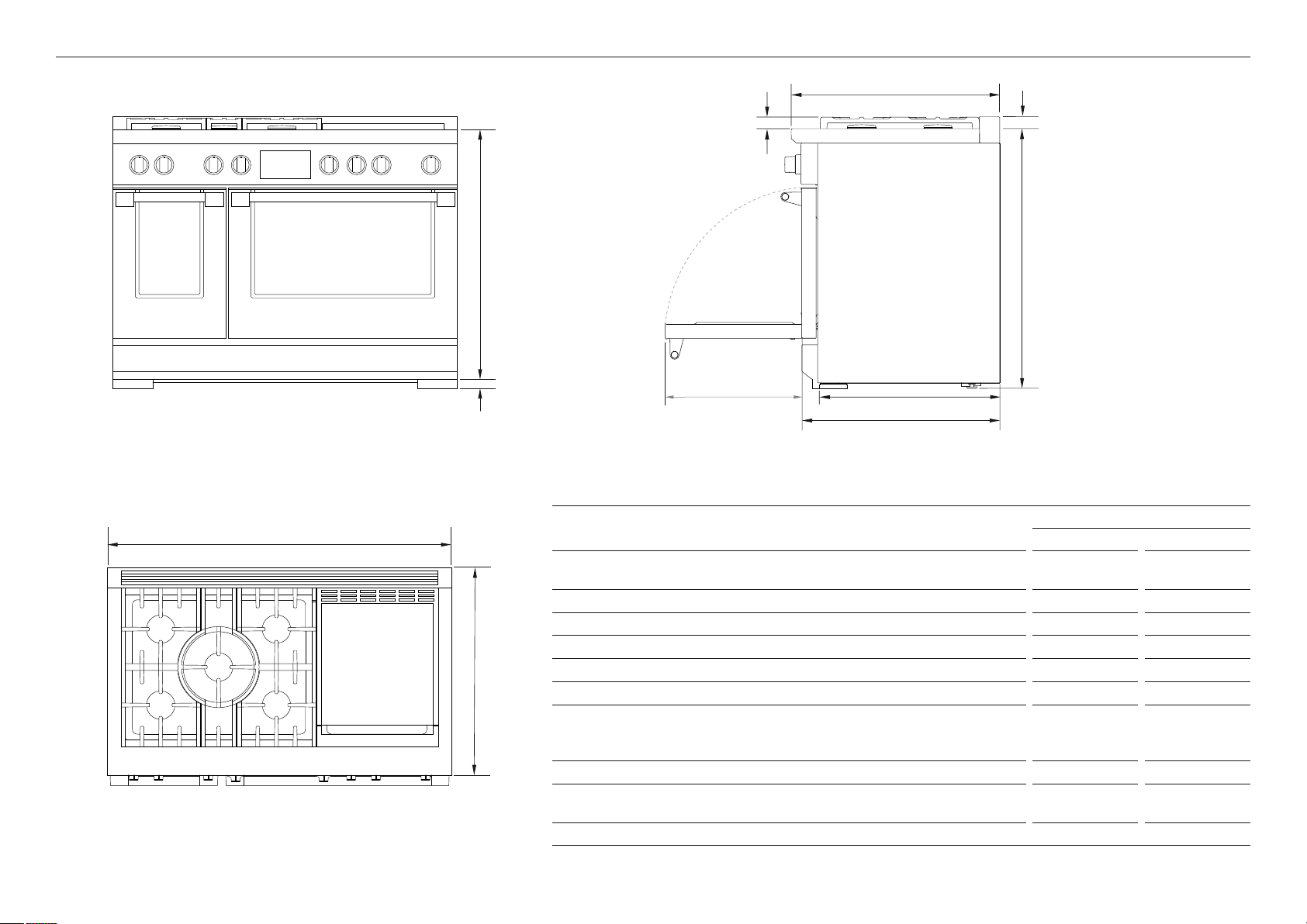
PRODUCT DIMENSIONS–48" MODELS
C
B
PLAN
C
H
I
F
G
A
J
D
E
PROFILEFRONT
PRODUCT DIMENSIONS
A Overall height of range
(from floor to cook surface, excl. pan supports andvent trim)
48" MODELS
IN MM
min 35 3/4
max 36 3/4
min 908
max 933
B Overall width of range 47 7/ 8 1216
C Overall depth of range (excl. handle and dials) 29 1/8 740
D Depth of chassis 25 3/8 644
E Depth from rear of chassis to front of control panel 27 11/16 703
F Height from top of cook surface to top of pan supports 1 9/16 40
G Height from top of cook surface to top of
zz
vent trim (as illustrated)
zz
angled vent trim (if fitted)
1 3/4
3 1/2
45
90
H Height from top of cook surface to bottom of chassis 35 1/4 895
I Adjustable feet height min 1/2
max 1 1/2
min 13
max 38
J Depth of open door to front control panel 19 1/8 486
7

A
CLEARANCE DIMENSIONS–ALL MODELS
E
B
D
C C
H
G
electrical
and gas
F
ISO
FRONT
CLEARANCE DIMENSIONS
30" MODELS 36" MODELS 48" MODELS
IN
MM
IN MM IN MM
A Minimum width of ventilation hood installed above range 30 762 36 914 48 1219
B Minimum vertical distance between countertop and cabinet extending above counter 18 457 18 457 18 457
C Minimum clearance from left and right edge of range to nearest vertical combustible surface 12 305 12 305 12 305
D Minimum clearance from cook surface to:
zz
combustible surface centered above the cook surface
zz
combustible covering for ventilation hood centered above the cook surface
zz
non-combustible surface* centered above the cook surface
36
30
1372
914
762
54
36
30
1372
914
762
54
36
30
1372
914
762
54
E Maximum overall depth of overhead cabinetry 13 330 13 330 13 330
F Width of cabinetry opening 30 762 36 914 48 1219
G Maximum height from floor to countertop:
– for level counter
– with range levelling legs fully extended
35 3/4
36 3/4
908
933
35 3/4
36 3/4
908
933
35 3/4
36 3/4
908
933
H Maximum depth from wall to cabinetry face:
zz
projecting control panel
zz
flush control panel
*Non-combustible surfaces: as defined in ‘National Fuel Gas Code’ (ANSI Z223.1, Current Edition). Clearances from non-combustible materials are not part of the ANSI Z21.1 scope and
are not certified by UL. Clearances of less than 6" (152mm) must be approved by the local codes and/or by the local authority having jurisdiction.
8
25 1/8
27 11/16
638
703
25 1/8
27 11/16
638
703
25 1/8
27 11/16
638
703
Note:
z
The cooking surface must sit flush or
above the adjacent countertop level.
z
If the range is to be placed adjacent
to cabinets, the clearances shown are
required. The same clearances apply
to island installations.
z
The range can be placed in various
positions with respect to the cabinet
front, with the control panel either
flush or projecting, depending on the
cabinetry depth.
z
The electrical and gas supply should
be within the zones shown in the
following diagrams
z
Any openings in the wall behind the
range and in the floor under the range
must be sealed.
z
Always keep the appliance area clear
and free from combustible materials,
gasoline and other flammable vapors
and liquids.
z
Do not obstruct the flow of combustion
and ventilation air to the unit.
 Loading...