


Fisher & Paykel OR90SCG6X1, OR90SCG1X1, OR90SCG6B1, OR90SCG4X1, OR90SCG6R1 Installation Guide
...
FREESTANDING RANGE
OR90 Dual Fuel
models
INSTALLATION GUIDE
NZ AU


1SAFETY AND WARNINGS
WARNING!
Electrical shock hazard
Before carrying out any work on the electrical section of the appliance,
it must be disconnected from the mains electricity supply.
Connection to a good ground wiring system is absolutely essential
and mandatory.
Alterations to the domestic wiring system must only be made by a
qualified electrician
Failure to follow this advice may result in electrical shock or death.
WARNING!
Cut Hazard
Take care – some edges are sharp.
Failure to use caution could result in injury or cuts.
WARNING!
To reduce the risk of tipping the appliance, the appliance must
be secured by properly installed anti-tip device packed with
the appliance.
●
A child or adult can tip the range and be killed.
●
Install the anti-tip device to the structure by fastening
the supplied bracket to the floor and wall following the
instructions for installing the anti-tip device.
●
Engage the anti-tip device.
●
Re-engage the anti-tip device if the range is moved.
Failure to do so can result in death or serious burns to children
of adults.
IMPORTANT SAFETY INSTRUCTIONS!
●
To avoid hazard, follow these instructions carefully before installing or using this appliance.
●
Please make this information available to the person installing the appliance - doing so could
reduce your installation costs.
●
This appliance must be installed according to AS/NZS 5601.1 (latest edition).
●
This appliance must be installed in accordance with these installation instructions.
●
This appliance shall only be serviced by authorized personnel.
●
This appliance is to be installed only by an authorised person in compliance with the current
electrical regulations gas codes and in observation of the instructions supplied by the
manufacturer. Failure to comply with this condition will render the guarantee invalid.
●
In the room where the range is installed, there must be enough air to allow the gas to burn
correctly, according to the current local regulations.
●
This appliance must only be installed in a permanently ventilated room in compliance with
the applicable regulations.
●
Isolating switch: make sure this range is connected to a circuit which incorporates an
isolating switch providing full disconnection from the power supply in accordance with the
wiring rules.
●
The range must be earthed.
●
Do not use adaptors, reducers or branching devices to connect the range to the mains
electricity supply, as they can cause overheating and burning.
●
Check for damage after unpacking and that the range door closes correctly.
●
The manufacturer accepts no responsibility for the incorrect installation of appliances.
Incorrect installation may result in personal injury, damage to property and may invalidate
any warranty or liability claims.
●
Do not modify this appliance.
●
Some models are supplied with a protective film on steel and aluminum parts.
●
This film must be removed before installing/using the appliance.
●
Packing elements (eg plastic bags, polystyrene foam, staples, packing straps etc) and tools
should not be left around during and after installation, especially if they are within easy
reach of children, as these may cause serious injuries.
●
Make sure you recycle the packaging material where possible.
●
Before disposing of any appliance, make sure that it can no longer be used and that all
hazardous parts are removed or made harmless, so that children playing with the old
appliance cannot harm themselves.
●
The various components of the appliance are recyclable. Dispose of them in accordance with
the regulations in force in your country. If the appliance is to be scrapped, remove the power
cord.
●
Be sure that the unit being installed is set up for the kind of gas being used. The gas range
is shipped from the factory set and adjusted for Natural Gas. It can be converted for use with
ULPG following the instructions in this manual.
IMPORTANT!
SAVE THESE INSTRUCTIONS
The models shown in this installation guide may not be available in all markets and are subject to change at any time. For current details about model and specification availability in your country,
please go to our website fisherpaykel.com or contact your local Fisher & Paykel dealer.
3

2GENERAL INSTALLATION INFORMATION
Cleaning and servicing
●
Service should only be performed by an authorised technician.
●
When removing appliance for cleaning and/or service:
●
Shut off gas at main supply.
●
Disconnect AC power supply.
●
Disconnect gas line to the inlet pipe.
●
Carefully remove the range by pulling outward.
●
CAUTION: Range is heavy; use care in handling.
●
The misuse of oven door (eg stepping, sitting, or leaning on them) can result
in potential hazards and/or injuries.
●
When installing or removing the range for service, a rolling lift jack should be used.
Do not push against any of the edges of the range in an attempt to slide it into or
out of the installation. Pushing or pulling a range (rather than using a lift jack) also increases
the possibility of bending the leg spindles or the internal coupling connectors.
IMPORTANT!
●
Range is heavy, use care in handling.
●
Do not lift the range by the oven door handle or hob rail, or by lifting the cooktop trim as
this may damage the appliance.
Replacement parts
Only authorised replacement parts may be used in performing service on the range.
Replacement parts are available from factory authorised parts distributors.
Contact the nearest parts distributor in your area.
PRODUCT LABEL
4

3PARTS SUPPLIED FOR INSTALLATION
Anti-tip bracket
and lock pin (1)
Screws and plastic
sleeve anchors (2)
Pressure regulator (1) Test point adapter (1) brass conical adapter
4TOOLS NEEDED FOR INSTALLATION (NOT SUPPLIED WITH THE APPLIANCE)
IMPORTANT!
THIS APPLIANCE MUST BE INSTALLED BY A QUALIFIED INSTALLER.
●
Improper installation, adjustment, alteration, services, or maintenance can cause injury or property damage.
Consult a qualified installer, service agent, or the gas supplier.
●
The use of suitable protective clothing/gloves is recommended when handling or installing this appliance.
and gasket (1)
Screwdriver 2 – Wrench T-handle
wrench
Pencil Tape measure Suitable
protective gloves
Hammer Adjustable
wrench
Adjustable
pliers
Drill
5

Model features may vary
OR90 MODELS
OR90SCG1
OR90SCG2
OR90SCG4
OR90SCG6
OR90SDG6
5MODEL IDENTIFICATION
6PRIOR TO INSTALLATION
Unpacking and handling
●
Inspect the range to verify that there is no shipping damage. If any damage is detected, call the shipper and initiate a damage claim. Fisher & Paykel is not responsible for shipping damage.
●
DO NOT discard any packing material until the range has been inspected.
●
Remove the outer carton and any packing material from range. Some models are supplied with a protective film on steel and aluminum parts.
This film must be removed before installing or using the appliance.
6

7PRODUCT DIMENSIONS
NOTE: Model features may vary
Optional kickstrip is available (purchased separately)
A
FRONT
E
F
G
C
SIDE
D
C
B
TOP
PRODUCT DIMENSIONS
Overall height of range
A
(from floor to top of cooktop, excluding grates and optional backguard)
Overall width of range
B
Overall depth of range
C
(from front of range to rear of backguard, excluding handles and dials)
Height of optional backguard from top of cooktop
D
(supplied with some models only)
Height of chassis (excluding adjustable feet)
E
F
Adjustable feet height
G
Depth of open door to front of range
OR90 DUAL FUEL
mm
min. 898
max 946
897
600
60
813
min. 85
max. 133
451
7
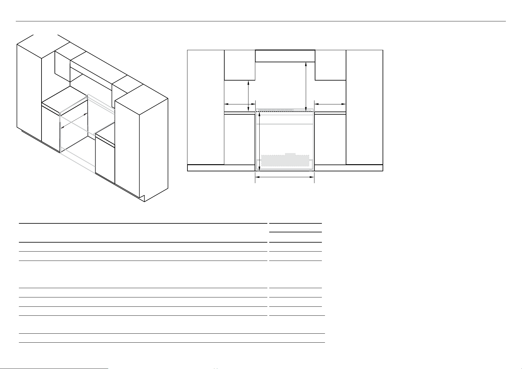
8CLEARANCE DIMENSIONS
A
F
ISO
CLEARANCE DIMENSIONS
Minimum vertical distance between benchtop and cabinet extending above counter 450
A
Minimum clearance from left and right edge of cooker to nearest vertical combustible surface*
B
Minimum clearance from cooking surface to:
C
– Overhead cabinet centered above the cooktop (combustible/unprotected)*
– Overhead cabinet centered above the cooktop (non-combustible/protected)*
– Ventilation hood centered above the cooking surface
Width of cabinetry opening 900
D
Maximum height of cabinetry immediately adjacent to the range (from floor to countertop)**
E
Maximum depth from wall to cabinetry face
F
* Installation clearances and protection of combustible surfaces shall comply with the current local regulations eg. AS/NZS5601.1 (latest edition)
Gas Installations code. The standards above specify that where required protection shall ensure that the surface temperature of the combustible
surface does not exceed 65°C above room temperature.
** Depending on the height of the feet adjustment. The cooking surface must sit flush or above countertop level.
COOKING SURFACE
E
Electrical & Gas
(see diagrams following)
D
FRONT
OR90 DUAL FUEL
C
mm
200
650
450
750
946
600
Note
Overhead Clearances
●
In no case shall the clearances between
the highest part of the cooker be less
than 650mm or for an overhead exhaust
fan 750 mm. All other downward facing
combustible surfaces less than 650
mm above the cooker surface shall
BB
be protected for the full width of the
cooking surface in accordance with the
standards noted above. In no case shall
the clearance be less than 450 mm.
Rear and Side Clearances
●
Where the dimensions from the
periphery of the nearest burner to any
vertical combustible surface is less than
200 mm the surface shall be protected
in accordance with the standards to a
height of not less than 150 mm above
the cooking surface for the full width or
depth of the cooking surface.
●
Where the dimensions from the
periphery of the nearest burner to any
horizontal combustible surface is less
than 200 mm, the horizontal surface
shall be greater than 10 mm below the
surface of the hob, or the horizontal
surface requirement above.
●
Do not install the range near flammable
materials such as curtains.
Installing the range on a plinth
●
The range can be installed on a plinth
without the adjustable feet fitted.
●
Ensure the range is secure and provide
safety measures to keep it in place.
●
Cabinetry dimensions can be adjusted
to suit the plinth height, see product
dimensions for chassis height.
8
 Loading...