


Fisher & Paykel RDV-364GL, RDV-485GD, RGU-366, RGU-485GD, RGU-486GL User Manual
...
Professional range
RGU, RDU, RGUC/RGVC,
RDV, RGV & RGVC models
Installation instructions
La cuisinière professionnelle
Modèles RGU, RDU, RGUC/RGVC,
RDV, RGV et RGVC
Guide d’installation
US CA

WARNING!
To reduce the risk of tipping the
appliance, the appliance must be secured
by properly installed anti-tip device
packed with the appliance.
A child or adult can tip the range
and be killed.
Install the anti-tip device to the
structure by fastening the
supplied bracket to the floor and
wall following the instructions for
installing anti-tip device.
Engage the anti-tip device.
Re-engage the anti-tip device if
the range is moved.
See installation instructions for
details.
Failure to do so can result in death or
serious burns to children of adults.
MISE EN GARDE!
Pour réduire le risque de basculer l’appareil,
il doit être fixé correctement par le dispositif
antibasculement fourni avec l’appareil.
Un enfant ou un adulte peut faire
basculer la cuisinière et être tué.
Installez le dispositif antibasculement
pour la structure de fixation du support
fourni à l’étage et mur en suivant
les instructions pour installer le dispositif
antibasculement.
Engager l’anti-dispositif de pointe.
Ré-engager le dispositif antibasculement
si la plage est déplacée.
Voir les instructions d’installation pour
plus de détails.
Le non-respect peut entraîner des brûlures
graves voire la mort aux enfants des adultes.
WARNING!
If the information in this manual is not
followed exactly, a fire or explosion may
result causing property damage, personal
injury or death.
Do not store or use gasoline or other
flammable vapors and liquids in the vicinity
of this or any other appliance.
NEVER use this appliance as a space heater
to heat or warm the room. Doing so may
result in carbon monoxide poisoning and
overheating of the appliance.
WHAT TO DO IF YOU SMELL GAS
Do not try to light any appliance.
Do not touch any electrical switch.
Do not use any phone in your building.
Immediately call your gas supplier from a
neighbor’s phone. Follow the gas supplier’s
instructions.
If you cannot reach your gas supplier, call the
fire department.
Installation and service must be performed by
a qualified installer, service agency or the gas
supplier.
MISE EN GARDE!
Le fait de ne pas suivre toutes les instructions
de ce manuel peut provoquer un feu ou une
explosion causant des dommages matériels,
des blessures ou la mort.
Ne rangez et n'utilisez pas de l’essence ou
d’autres liquides et vapeurs inflammables à
proximité de cet appareil ou de tout autre
appareil.
N'utilisez JAMAIS cet appareil pour chauffer
une pièce. Le non-respect de cette consigne
peut causer un empoisonnement au monoxyde
de carbone et une surchauffe de l'appareil.
QUE FAIRE SI VOUS DÉCELEZ
UNE ODEUR DE GAZ
Ne tentez d’allumer aucun appareil.
Ne touchez à aucun interrupteur électrique.
N'utilisez aucun téléphone dans l'édifice.
Appelez immédiatement votre fournisseur
de gaz en utilisant le téléphone d’un voisin.
Suivez les consignes du fournisseur de gaz.
S’il vous est impossible de joindre votre
fournisseur de gaz, appelez le service d’incendie.
L’installation et l’entretien doivent être effectués
par un installateur ou un technicien qualifié, ou
par un employé de votre fournisseur de gaz.
A MESSAGE TO OUR CUSTOMERS
Thank you for selecting this professional Range. Because of this appliance’s unique features we have developed
this Installation Guide. It contains valuable information on how to properly install your new appliance for years of
safe and enjoyable cooking.
For your convenience, product questions can be answered by a DCS Customer Care Representative by phone:
1-888-936-7872, or email:
NOTE: Please write the Model and Serial Numbers on this page for references (located on the label above the kick
panel on the right)
MODEL NUMBER SERIAL NUMBER
NOTE: Inspect the product to verify that there is no shipping damage. If any damage is detected, call the shipper
and initiate a damage claim. DCS by Fisher & Paykel is not responsible for shipping damage.
DO NOT discard any packing material (box, pallet, straps) until the unit has been inspected.
customer.care@fisherpaykel.com
.
1
US
CA
WARNING
Improper installation, adjustment alteration, service or maintenance can cause property damage, injury or death.
Read the installation, operating and maintenance instructions thoroughly before using, installing or servicing this
appliance.
A risk of the appliance tipping over exists if the appliance is not installed in accordance with installation instructions.
WARNING
To reduce the risk of injury to persons in the event of a rangetop grease fire, observe the following: Turn burner off
first. Smother flames with a close-fitting lid, cookie sheet, metal tray, baking soda or use a dry chemical or foam-type
fire extinguisher. Be careful to prevent burns. If the flames do not go out immediately, evacuate and call the fire
department. Never pick up a flaming pan - You may be burned. DO NOT USE WATER ON GREASE FIRES, including
wet dishcloths or towels - a violent steam explosion will result. Use an extinguisher ONLY if:
1. You know you have a Class ABC extinguisher, and you already know how to operate it.
2. The fire is small and contained in the area where it started.
3. The fire department is being called.
4. You can fight the fire with your back to an exit.
Important!
Installer: leave this manual with the customer.
Customer: please retain this manual for future reference and for the local inspector’s use.

US
CA
2

TABLE OF CONTENTS
SAFETY PRACTICES AND PRECAUTIONS 4
MODELS 7
PLANNING THE INSTALLATION 8
UNPACKING AND HANDLING 9
VENTILATION REQUIREMENTS 12
INSTALLING ANTITIP DEVICE 13
CABINET PREPARATION 14
BACKGUARD INSTALLATION 19
ELECTRICAL CONNECTIONS 19
GAS HOOKUP 21
TEST AND ADJUSTMENTS 22
CLEANING EXTERIOR SURFACES 23
3
US
CA
INSTALLER FINAL CHECKLIST 24
SERVICE 25

4
SAFETY PRACTICES AND PRECAUTIONS
US
CA
When properly cared for, your new DCS Appliance has been de signed to be a safe, reliable cooking appliance.
When using this restaurant caliber appliance, use it with extreme care, as this type appliance provides intense
heat and can increase the accident potential. Basic safety precautions must be followed when using kitchen
appliances, including the following:
■
Read the user guide, which came with this appliance, thoroughly before using your new appliance. This will help
to reduce the risk of fire, electric shock, or injury to persons.
■
Begin by insuring proper installation and servicing. Follow the installation instructions in this manual. Be sure to
have a qualified technician install and ground this appliance before using.
■
Have the installer show you where the gas supply shut-off valve is located.
■
If you smell gas, the installer has not done a proper job of checking for leaks. Shut the gas to the appliance off
and follow the instructions on the inside front cover of this manual. Do not attempt to find the leak yourself. This
must be done by a qualified service technician only.
■
If by some chance a burner goes out and gas escapes, open a window or a door to let the room air out. Do not
attempt to use the appliance until the gas has had time to dissipate. Follow the instructions on the inside front
cover of this manual.
■
This appliance has been factory assembled for natural or LP gas. It should be correctly ad justed from the factory
for the type of gas that is used.
■
Do not repair or replace any part of this appliance unless it is specifically recommended in this manual. All other
servicing should be referred to a qualified technician.
■
Children should not be left alone or unattended in an area where appliances are in use. They should never be
allowed to turn knobs, push buttons, sit or stand on, and/or touch any part of an appliance while in operation.
■
Children in walkers, or children crawling can be attracted to the oven door handle and may grab and open the
oven door. This can result in injury from the door being pulled open on a child, or severe burns if the oven is in
use and hot.
WARNING:
Do not store items of interest to children above or at the back of any appliance. Children could be seriously injured
if they should climb onto the appliance to reach these items.
■
Never store anything in the oven or on the cooktop. Flammable materials can catch fire, plastic items may melt
or ignite and other types of items could be ruined.
■
Do not hang articles from any part of the appliance or place anything against the oven. Some fabrics are quite
flammable and may catch on fire.
■
If the appliance is near a window be certain the curtains do not blow over or near the cooktop burners; they
could catch on fire.
■
Keep rugs and mats well clear of the base of the range.
■
Do not use water on grease fires. Turn all burners “OFF”, then smother fire with baking soda or use a dry
chemical or foam-type fire extinguisher.
■
Never let clothing, pot holders, or other flammable materials come in contact with, or too close to, any burner or
burner grate until it has cooled. Fabric may ignite and result in personal injury.
■
Be certain to use only dry pot holders: moist or damp pot holders on hot surfaces may cause burns from steam.
Do not use a towel or other bulky cloth in place of pot holders. Do not let pot holders touch hot burners, or
burner grates.

SAFETY PRACTICES AND PRECAUTIONS
■
For personal safety, wear proper apparel. Loose fitting garments or hanging sleeves should never be worn while
using this appliance. Some synthetic fabrics are highly flammable and should not be worn while cooking.
■ Do not use aluminum foil to line any part of the oven or cooktop. This will cause heat to be trapped underneath
it. This trapped heat can upset the cooking perfor mance and can damage the finish of the oven or the cooktop
parts.
■
WARNING! NEVER cover any slots, holes or passages in the oven bottom or cover
an entire rack with materials such as aluminum foil. Doing so blocks airflow through the oven and may
cause carbon monoxide poisoning. Aluminum foil linings may also trap heat, causing a fire hazard.
This appliance is for cooking. Never use the oven or cooktop to warm or heat a room. This could damage the
cooktop or oven parts.
■
When using the cooktop: Do not touch the burner grates or the immediate surrounding area. Areas adjacent to
the burners may become hot enough to cause burns.
■
When using the oven: Do not touch the interior surfaces of the oven, the exterior area immediately surrounding
the door or the back trim. The surfaces directly above the oven door may be hot if the oven has been operated
with the door open, or if something has prevented the door from sealing.
5
US
CA
■
Never leave the cooktop unattended when using high flame settings. When cooking with high flame settings,
boilovers may cause smoking and greasy spillovers may ignite. More importantly, if the burner flames are
smothered by a severe boilover which affects the igniter, unburned gas will escape into the room.
■
Only certain types of glass, heat-proof glass-ceramic, ceramic, earthen ware, or other glazed utensils are suitable
for cooktop use. Some utensils may break with sudden temperature changes. Use only on low or medium
flames settings according to the manufacturer’s directions. The use of professional utensils is recommended.
■
Do not heat unopened food containers; a build up of pressure may cause the container to burst.
■
During cooking, set the burner control so that the flame heats only the bottom of the pan and does not extend
beyond the bottom of the pan. This could heat and/or melt the handles, and may increase cooking time.
■
Always use utensils that have flat bottoms large enough to cover the burner. The use of undersized utensils will
expose a portion of the flame to direct contact and may result in ignition of clothing.
■
To minimize burns, ignition of flammable materials and unintentional spill overs, position handles of utensils
inward so they do not extend over adjacent work areas, cooking areas, or the edge of the cooktop.
■
Hold the handle of the pan to prevent movement of the utensil when stirring or turning food.
■
Grease is flammable. Let hot grease cool before attempting to handle it. Avoid letting grease deposits collect
around the cooktop burners. Clean after each use or boil over.
■ Do not remove the grease drip-pan from the griddle or grill until completely cool.
■
For proper lighting and performance of the cooktop burners, keep the burner ports clean. It may be necessary
to clean these when there is a boil over or when the burner does not light, even though the electronic igniters
click.
■
Do not use the grill for cooking excessively fatty meats or products which promote flare-ups. Do not use
cooking utensils on the grill.

6
Gas supply line
Installer-supplied
shut-o valve
“open” position
SAFETY PRACTICES AND PRECAUTIONS
US
CA
■
Clean the cooktop with caution. Avoid steam burns; do not use a wet sponge or cloth to clean the cooktop while
it is hot. Some cleaners produce noxious fumes if applied to a hot surface. Follow directions provided by the
cleaner manufacturer.
■
Be sure all the range and/or cooktop controls are turned off and the appliance is cool before using any type
of aerosol cleaner on or around the appliance. The chemical that produces the spraying action could, in the
presence of heat, ignite or cause metal parts to corrode.
■
Place oven racks in desired position while the oven is cool. If a rack must be moved while the oven is hot, do not
let the pot holders contact the hot interior of the oven.
■
Use care when opening the oven door; let hot air or steam escape before removing or replacing foods.
■
Do not rub, damage, move or remove the door gasket. It is essential for a good seal during baking. Wash the
gasket with hot water only.
■
Clean the ventilator hood and filters above the range or cooktop frequently so grease from cooking vapors does
not accumulate on them. The filters can be cleaned in a dishwasher or DishDrawer. Follow directions provided
by ventilation manufacturer for cleaning.
■
Turn the ventilator “OFF” in case of fire or when intentionally “flaming” liquor or other spirits on the cooktop.
The blower, if in operation, could unsafely spread the flames.
■
DO NOT obstruct the flow of combustion or ventilation air to the appliance. Be sure a fresh air supply is
available.
■
For safety reasons and to avoid damage to the appliance never sit, stand, or lean on the oven door or cooking
■
Service should only be done by authorized technicians. Technicians must disconnect the power supply before
■
The gas supply connections should be made by a qualified technician in accordance with local codes or
■
A manual shut-off valve (supplied by the installer) must be installed in an accessible location
■
The gas supply line must not protrude beyond the back of the appliance as this would prevent the product from
■
Make sure the gas supply is turned off at the wall valve before connecting the appliance.
surface.
servicing this appliance.
WARNING:
California Proposition 65 - The burning of gas cooking fuel generates some by-products which are known by the
State of California to cause cancer or reproductive harm. California law requires businesses to warn customers
of potential exposure to such substances. To minimize exposure to these substances, always operate this unit
according to the manufacturer’s instructions and provide good ventilation to the room when cooking with gas.
REQUIREMENTS FOR HOOKUP TO GAS SUPPLY
ordinances. In the absence of a local code, the installation must conform to the latest edition of National Fuel
Gas Code ANSI Z.223.1 (Warning: this appliance must be installed by a licensed plumber or gas fitter when within
the Commonwealth of Massachusetts).
in the gas line external to the appliance for the purpose of turning on or shutting off gas to
the appliance. (In Massachusetts such shut-off valves should be approved by the Board of
State Examiners of Plumbers & Gas Fitters.) The shut-off valve must be located within 6 feet
(1.8 metres) of the appliance it serves.
Important!
Fisher & Paykel recommends installing the manual shut-off valve in a location readily
accessible by the customer, so that gas to the appliance can be shut off in an emergency
situation. However, the appliance must not be modified in any way to accommodate such placement.
being pushed completely against the wall.
■
Leak-testing of the appliance shall be conducted according to the manufacturer’s instructions. See instructions
in section ‘Test and adjustments’.

MODELS
48” models
7
US
CA
RGU484GG
RDU/RDV484GG
RGU/RGV485GD
RDU/RDV485GD
36” models
RGU/RGV486GL
RDU/RDV486GL
RGU/RGV486GD
RDU/RDV486GD
RGU/RGV366
RDU/RDV366
30” models
RGU/RGV364GL
RDU/RDV364GL
RGU/RGV305
RDU/RDV305
RGUC/RGVC305
RGU/RGV364GD
RDU/RDV364GD
US
CA
8
PLANNING THE INSTALLATION
IMPORTANT INSTALLATION INFORMATION
The range is tested in accordance with ANSI Z21.1 Standard for Household Cooking Gas Appliances.
The range must be installed in conjunction with a suitable overhead vent hood. (See section ‘Ventilation
Requirements’). Due to the professional high heat capacity of this unit, particular attention should be paid to
the hood and duct work installation to ensure it meets local building codes. To eliminate risk of burns or fire by
reaching over heated surface units, cabinet storage located above the surface units should be avoided.
All range models with less than a 12” clearance between combustible material and the back edge of the
range (above the cooking surface) require the installation of one of the two offered Backguards – see section
‘Backguard installation’.
■
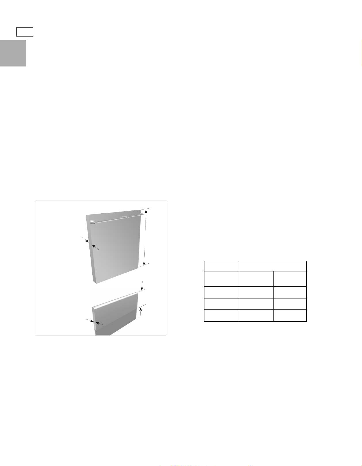
All ranges have a standard 3-1/2” integral island trim.
■
RGU/RGV and RGUC/RGVC ranges are supplied with a matching BGRU2-15xx standard backguard.
■
For RDU/RDV ranges, the backguard has to be purchased separately.
Wall Mount Full
Backguard
1-5/16”
26-1/2”
Model Number
Standard
Backguard
Range Mount
Standard
Backguard
13/16”
Fig.1 Backguards
Check local building codes for the proper method of range installation. Local codes vary. Installation, electrical
connections, and grounding must comply with all applicable codes. In the absence of local codes, the range
should be installed in accordance with the latest edition of National Fuel Gas Code ANSI Z223.1 and National
Electrical Code ANSI / NFPA 70.
11-13/32”
48” Range BGRU2-1548 BGRU-3048
36” Range BGRU2-1536 BGRU-3036
30” Range BGRU2-1530 BGRU-3030
Full
Backguard
Be sure that the unit being installed is set up for the kind of gas being used. The gas range is shipped from the
factory set and adjusted for Natural Gas or LP (propane), depending on the specific model ordered. Verify that
the range is compatible with the gas at the installation site before proceeding further. Return range to
dealer if the unit is not set for site gas supply.

PLANNING THE INSTALLATION
420-630 lb
190-285 kg
RECOMMENDED INSTALLATION SEQUENCE
Install components in the following order:
1. Locate and level range according to range installation instructions.
Steps 2,3 & 4 are only relevant if you are installing a Wall Mount Full Backguard:
2. Measure distance from floor to top of island trim on range, adding 1/4” for
backguard clearance.
3. Transfer this measurement to the wall. This will mark the bottom of your
backguard.
9
US
CA
Island Trim
4. From this line measure 26-1/4” up wall to mark the top of a Wall Mount Full
backguard. This is the minimum height that the bottom of your vent hood can
be installed.
5. Follow vent hood manufacturer’s installation instructions to install vent hood.
6. Follow backguard installation instructions to install backguard.
7. Connect gas and electric connections and slide range into position.
NOTE:
A manual gas shut-off valve must be installed. See section ‘Gas Hook-up’.
UNPACKING AND HANDLING
WARNING!
Extremely Heavy
Proper equipment and adequate manpower must be used in moving
the range to avoid personal injury or damage to the unit or the
oor. The unit is heavy and rests on adjustable steel legs.
0”
Floor
Failure to follow this advice may result in damage or personal injury.
WARNING:
DO NOT lift range by the oven door handles!!
WARNING:
DO NOT remove the grill or griddle assemblies!!
MOVING AND PLACING THE RANGE
The ranges have shipping weights varying from 420 lbs. to 630 lbs less approx. 50lbs. after removal of packing
material. It is recommended that the door(s), grates, and front kick panel be removed to facilitate handling. This
will reduce the weight for ease of handling.
It may be necessary to remove the oven door(s) to pass through some doorways. With the door(s) removed, a
29-1/2” wide opening is required. Without removing the door, a 32” wide opening is required. Remove the outer
carton and packing material from the shipping base.

US
CA
10
UNPACKING AND HANDLING
MOVING AND PLACING THE RANGE cont.)
Anti-tip device should be installed (see section ‘Installing anti-tip
device’ for instructions). The professional range should be
transported by a dolly close to its final location. The range can
be tipped back and supported on the rear legs while the dolly is
removed. The floor under the legs should be protected (wood
strips, carpet, paneling, etc.) before pushing the unit back into
position.
Electric and gas connections should be made before the range is
slid into the cabinet opening (see sections ‘Electrical connections’
and ‘Gas hook-up’). If installing a full backguard with the range,
it should also be installed before the range is placed in its final
position (see sections ‘Planning the installation’ and ‘Backguard
installation’). For proper performance, the professional range
should be level. Flooring in cabinet opening must be at the
same level as flooring located in front of the cabinets. To achieve
a flush fit of the range to adjoining countertops, it will be
necessary to have level cabinets (front to back, and left to right
across opening of the range). After checking the countertops
for level and before sliding the range into place, measure the
distance from the floor to the top of the counter work surface
in the rear left and right corners. Adjust the corresponding rear
corner of the range to an equal height of the counter, as the rear
leveling legs are not accessible once the range is pushed into
place. Once the range is in place, the front leg levelers can be
accessed to level the front of the range. Replace the kick panel
and oven doors by reversing the procedure described further
below. It is important that the two screws retaining the kick
panel are secure to prevent accidental access to live electrical
components and wires (Fig. 2a).
To remove the kick panel:
Remove two screws at the top and pull forward. The range is
held to the skid by two bolts (RGU/RGV/RDU/RDV models) or
by L-brackets (RGUC/RGVC models) in the front, behind the
kick panel, and two L-brackets located on the bottom flange
of the range back (Fig. 2b). After removing the bolts and
brackets, the range must be lifted and removed from the skid.
Kick Panel
(RDU, RGU & RGUC models)
Kick Panel
(RDV, RGV & RGVC models)
Fig. 2a
Left Rear
Left Rear Shipping
Shipping Screws
Screws
Due to the weight, a dolly with soft wheels should be used
to move this unit. The weight must be supported uniformly
across the bottom (Fig. 3).
CAUTION: RGUC/RGVC MODELS ONLY
Before using the range, be sure to remove shipping spacer
insert in the broiler (see Fig. 4).
Shipping
Spacer
Fig. 4
Leveling Legs
Leveling Legs
Fig. 2b
Fig. 3
Range Must
Range Must
be Uniformly
be Uniformly
Supported
Supported on
on Braces
Braces
22"

UNPACKING AND HANDLING
To remove door:
WARNING!
Do not lift oven door by the handle - this will cause damage! Be sure
the oven and door are cool before you begin to remove the door!
11
US
CA
1. Open the door completely. (Fig. 5a).
2. Unlock the door hinges by rotating the lock forward (Fig. 5b).
3. Once both hinges are unlocked, gently close the door until
approximately halfway closed. Grabbing the sides of the door
and gently lifting up and slightly forward, the door will unlatch
from the hinge.
4. Continue to lift and pull the door away from the range.
To re-install door:
1. Position the door in approximately halfway open position.
2. Simply place the hinge tongue into the hinge slots (See Fig. 6a).
3. Push the door into the slots until you feel them fall into the
latches.
4. Open the door completely and rotate the locks into the closed
position (Fig. 6b).
5. Close the oven door.
Fig. 5a Oven hinge assembly
Fig. 5b Hinge retainer clip in unlocked position
hinge tongue
hinge slot
Fig. 6a Hinge assembly
Fig. 6b Hinge retainer clip in locked position

US
CA
12
VENTILATION REQUIREMENTS
A suitable exhaust hood must be installed above the range. The following chart indicates the minimum blower
capacity recommended for hood ventilation.
Standard Counter
Ventilation Unit
Installation
Recommendatons
HOOD 23” Deep x Unit Width 30” Deep x 36” at Bottom
48” Range
1200 CFM
BLOWER
* 36” ranges featuring a grill (GL models) require a 1200 CFM ventilation unit
36” Range*
600-1200 CFM
30” Range
600 CFM
Island Installation
Recommendatons
1200 CFM
600-1200 CFM
600 CFM
CAUTION:
Ventilation hoods and blowers are designed for use with single wall ducting. However, some local building codes
or inspectors may require double wall ducting and/or a damper. Consult local building codes and/or local agencies,
before starting, to ensure that hood and duct installation will meet local requirements.
Hood blower speeds should be variable to reduce noise and loss of heated or air conditioned household air
when maximum ventilation is not required. Normally, the maximum blower speed is only required when using
the grill or the self-cleaning cycle.
For best smoke elimination, the lower edge of the hood should be installed a minimum of 30” to a maximum of
36” above the range cooking surface, (see section ‘Cabinet Preparation’). If the hood contains any combustible
materials (e.g. a wood covering) it must be a minimum of 36” above the cooking surface.
Due to a high volume of ventilation air, a source of make-up air (outside replacement air) is recommended. This
is particularly important for tightly sealed and insulated homes. A reputable heating and ventilating contractor
should be consulted.

INSTALLING ANTITIP DEVICE
All ranges must have an anti-tip device correctly
installed as per the following instructions. If you pull
the range out from the wall for any reason, make sure
that the device is properly engaged when you push
the range back against the wall. If it is not, there is
a risk of the range tipping over and causing injury
if you or a child stand, sit or lean on an open oven
door.
INCLUDED PARTS:
(4) #10 x 2” wood screws, (2) 5/16 x 1 -1/2” sleeve
anchors, (2) lag bolts and washers and
(1) Anti-tip bracket, and (1) Installation Instructions.
INSTALLING THE KIT:
Instructions are provided for wood and cement
floors. Any other type of construction may require
special installation techniques as deemed necessary
to provide adequate fastening of the Anti-tip bracket
to the floor and wall. The use of this bracket does
not preclude tipping of the range when not properly
installed.
WOOD CONSTRUCTION:
Place the bracket against the back wall, into the right
rear corner where the range is to be located. Leave a
gap between the wall (or side of range) and the bracket
(see Fig. 8). Drill (2) 1/8” diameter pilot holes in the
center of the small holes. A nail or awl may be used if a
drill is not available. Fasten the bracket securely to the
floor and wall.
CONCRETE OR CEMENT CONSTRUCTION:
Locate the bracket as described above.
Using the bracket as a template, drill (2x) 5/16”
diameter pilot holes in the centre of the larger holes to
a depth of at least 1- 3/4” . Place the sleeve anchors into
the holes and use a hammer to tap them all the way in.
Tighten the nuts on the sleeve anchors to fasten the
bracket securely to the floor.
For all installations:
(2) Small Holes for Wood
(2) Large Holes for Concrete
Installations
Model
Series
A
Installations
A
Fig. 8
RGU/RGV-48, RDU/RDV-48
RGU/RGV-36, RDU/RDV-36
RGU/RGV-30, RDU/RDV-30
1/2” 5/8”
A child or adult can tip the range
and be killed.
Install the anti-tip device to the
structure.
Engage the anti-tip device.
Re-engage the anti-tip device if
the range is moved.
See installation instructions for
details.
Failure to do so can result in death or
serious burns to children of adults.
13
US
CA
(2) Wood Screws into Back
Wall (ALL Installations)
BACK
WALL
RIGHT SIDE OF
WALL OR RANGE
RGUC/RGVC-30
WARNING!
Fasten the bracket to the back wall using the two holes
on the top of the bracket. Follow the method described
in ‘wood construction’.
ONCE INSTALLED:
Complete the range installation per the instructions
provided with the product. Check for proper installation
of the range and Anti-tip device by grasping the back of
the unit and carefully attempt to tilt the range forward.
Fig. 9

14
CABINET PREPARATION
US
CA
1. The range is a free standing unit. If the unit is to be placed adjacent to cabinets, the clearances shown in the
following diagrams are required. The same clearances apply to island installations.
2. The range can be placed in various positions with respect to the cabinet front, with the front frame either flush
or projecting, depending on the countertop depth.
3. The electrical and gas supply should be within the zones shown in the following diagrams.
4. A manual shut-off valve (supplied by the installer) must be installed in an accessible location in the gas line
external to the appliance for the purpose of turning on or shutting off gas to the appliance. (In Massachusetts
such shut-off valves should be approved by the Board of State Examiners of Plumbers & Gas Fitters.) The shut-off
valve must be located within 6 feet (1.8 metres) of the appliance it serves.
Important!
Fisher & Paykel recommends installing the manual shut-off valve in a location readily accessible by the customer,
so that gas to the appliance can be shut off in an emergency situation. However, the appliance must not be
modified in any way to accommodate such placement.
5. The maximum depth of over head cabinets installed on either side of the hood is 13”.
6. Any openings in the wall behind the range and in the floor under the range must be sealed.
7. When there is less than a 12” clearance between combustible material and the back edge of the range (above
the cooking surface), a DCS Standard backguard or Full backguard must be installed. When clearance to
combustible material is over 12” no backguard is necessary. RGU/RGV and RGUC/RGVC models are supplied with
a matching BGRU2-15xx standard backguard. For RDU/RDV models, the backguard must be ordered separately,
(see section ‘Planning the installation’). See Fig. 13 for an illustration of all the installation options.
8. Always keep the appliance area clear and free from combustible materials, gasoline and other flammable vapors
and liquids.
9. Do not obstruct the flow of combustion and ventilation air to the unit.
10. The horizontal surfaces of the range top (cooktop) trim must not be below countertop level.

CABINET PREPARATION
E
15
US
CA
A
C
Fig. 10 Cabinetry dimensions
B
D
Cooking surface
H
C
G
see diagrams
following for
electrical and gas
connection details
F
Cabinetry dimensions
minimum width of ventilation hood installed above
A
range
minimum vertical distance between countertop and
B
cabinet extending above counter
minimum clearance from left and right edge of range to
C
nearest vertical combustible surface
minimum clearance from cooking surface to:
- combustible surface centered above the
cooking surface
D
- non-combustible surface centered above the
cooking surface
maximum overall depth of overhead cabinetry
E
width of cabinetry opening
F
maximum height from floor to countertop:
- for level counter
G
- with range levelling legs fully extended
maximum depth from wall to cabinet front
H
RGU/RGV-48
RDU/RDV-48
48” 36” 30”
18” 18” 18”
12” 12” 12”
51”
30”
13” 13” 13”
48” 36” 30”
35-3/4”
36-3/4”
25” 25” 25”
RGU/RGV-36
RDU/RDV-36
51”
30”
35-3/4”
36-3/4”
RGU/RGV-30
RDU/RDV-30
RGUC/RGVC-30
51”
30”
35-3/4”
36-3/4”
 Loading...