


Fisher Paykel CG365DNGRX2N Installation Manual

GAS COOKTOP
CG65DW models
INSTALLATION GUIDE
US CA
590686 D 08.17
1 SAFETY AND WARNINGS
!
WARNING!
Electrical Shock Hazard
Disconnect product from the mains power supply before servicing. This
appliance is equipped with a three-prong grounding plug for your
protection against shock hazard and should be plugged directly into a
properly grounded power outlet. Do not under any circumstances cut or
remove the grounding prong from this plug.
Failure to follow this advice may result in electrical shock or death.
!
WARNING!
Cut Hazard
Take care - panel edges are sharp.
Failure to use caution could result in injury or cuts.
IMPORTANT SAFETY INSTRUCTIONS
●
This appliance shall be installed in accordance with the installation requirements of the
local gas authority or the appropriate installation code or in the absence of local codes
with the latest National Fuel Gas Code NFPA 54/ANSI Z223.1 or CAN/CSA B149.1,2
(Canada). Local building and electrical codes must be adhered to.
●
Electrical installation must be in accordance with the National Electrical Code, ANSI/
NFPA70 - latest edition or CSA C22.1 (Canada) and/or local codes.
●
Installation in manufactured (mobile) home: installation must conform with the
Manufactured Home Construction and Safety Standard, Title 24 CFR, Part 3280 [formerly
the Federal Standard for Mobile Home Construction and Safety, Title 24, HUD (Part
280)] or, when such standard is not applicable, the Standard for Manufactured Home
Installations, ANSI/NFPA 225, or with local codes where applicable.
●
Installation in Recreational Park Trailers: installation must conform with state or other
codes or, in the absence of such codes, with the Standard for Recreational Park Trailers,
ANSI A119.5.
●
Do not remove permanently affixed labels, warnings, or plates from the product. This
may void the warranty.
●
Flexible appliance connectors shall meet the requirements of ANSI Z21.24 and State
Boards. They shall not exceed 35 1/2 inches (900 mm) in length. In order to avoid hazard,
these appliances must be installed according to these instructions.
●
This appliance must be installed by an authorized person (Warning: this appliance must
be installed by a licensed plumber or gas fitter when within the Commonwealth of
Massachusetts).
●
Please make this information available to the person installing the appliance as it could
reduce your installation costs.
●
Please leave these instructions with the appliance. Inform the customer to retain for
future reference and for the local inspectors’ use.
●
Failure to install the appliance correctly could invalidate any warranty or liability claims.
●
Leak testing of the appliance shall be conducted according to the manufacturer’s
instructions.
Only genuine replacement parts may be used for servicing the appliance. These are
available from your nearest Fisher & Paykel Service Center.
Before you install the appliance, please make sure that
●
the local distribution conditions (nature of gas and pressure) and the adjustment of the
appliance are compatible. For adjustment conditions for this appliance, see ‘Gas rate
summary’ under step 3.
●
a suitable isolating switch is incorporated in the fixed wiring in an acceptable position.
●
the appliance is connected to a power outlet that is electrically grounded in accordance
with local codes or in the absence of local codes, with the National Electric Code ANSI/
NFPA 70 or CSA C22.2 (Canada).
●
there is a power outlet (110-120V 60Hz) within reach of the appliance cable (35 1/2” (900
mm) from the center rear of the appliance). This must be accessible after installation. The
mains power supply cable should not touch any metal parts.
●
the countertop is square and level and no structural members interfere with space
requirements
●
the countertop is made of heat-resistant material.
●
you take note of the following recommended non-combustible materials: 1/4” (6 mm) flame
retardant millboard covered with not less than No. 28 MSG sheet steel, 1/32” (0.4 mm)
stainless steel,
●
1/32” (0.6 mm) aluminum or 1/32” (0.5 mm) copper.
●
the gas shut-off valve is accessible after installation.
●
if the power supply cable is damaged, it is replaced only by the special cable: Part no.
534901 Trml Block-flex Assy CG901 NZ US, obtainable from authorized Fisher & Paykel
Service Agents.
●
NOTE:
As servicing requires removing of the cooktop from the countertop we do not recommend
flush mounting. To the fullest extent permissible by law, the owner carries all risk for flush
mounting of the cooktop. The owner must ensure the cooktop has been cut out from the
benchtop before servicing can be carried out. Fisher & Paykel will not be liable for any
costs associated with removing or replacing a flush-mounted and/or sealed-in product,
nor for repairing any damage that may be incurred by doing this. Fisher & Paykel does not
exclude any statutory liability it may have and which by law cannot be excluded, because of
the giving of this notice.
IMPORTANT!
SAVE THESE INSTRUCTIONS
The models shown in this installation guide may not be available in all markets and are subject to change at any time. For current details about model and specification availability in your country, please go to our
website www.fisherpaykel.com or contact your local Fisher & Paykel dealer.
1
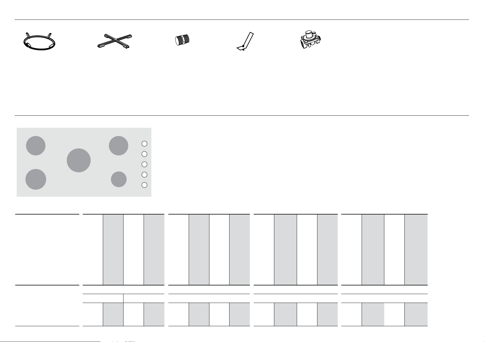
2 PARTS SUPPLIED
Wok stand (1)
Small pan
support (1)
SEMI-RAPID SEMI-RAPID
DUAL WOK
RAPID
CG365DW
AUX
Nipple 1/2 “
NPT thread (1)
3 GAS RATE SUMMARY
Clamping
brackets (6)
and screws (6)
Regulator (1)
High Altitude Installations
For installations above 3000’ conversion kits are required:
3,000-6,000’ 535315 KIT HI ALT LP 3-6K CG365 FLUSH
535317 KIT HI ALT NG 3-6K CG365 FLUSH
6000’+ 535316 KIT HI ALT LP 6-9K CG365 FLUSH
535318 KIT HI ALT NG 6-9K CG365 FLUSH
Contact your authorized dealer, customer care or refer to
the website listed at the back of this document.
US CA
INJECTOR ORIFICE (MM)
CG365DW AUX SEMI-RAPID RAPID DUAL WOK
0.9 3800 0.55 3500 1.35 8500 0.8 7600 1.45 9500 0.87 9000
NOMINAL RATING (BTU/HR)
NG LP NG LP NG LP NG LP
INJECTOR ORIFICE (MM)
NOMINAL RATING (BTU/HR)
INJECTOR ORIFICE (MM)
NOMINAL RATING (BTU/HR)
INJECTOR ORIFICE (MM)
NOMINAL RATING (BTU/HR)
INJECTOR ORIFICE (MM)
NOMINAL RATING (BTU/HR)
INJECTOR ORIFICE (MM)
NOMINAL RATING (BTU/HR)
INJECTOR ORIFICE (MM)
1.45
1.45
0.70
NOMINAL RATING (BTU/HR)
18500
0.80
0.80
0.50
INJECTOR ORIFICE (MM)
NOMINAL RATING (BTU/HR)
18000
2
A
K
D
B
E
C
G
F
J
H
I
TOP
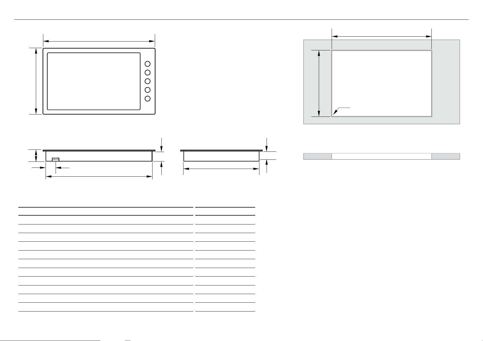
Note: Gas inlet connection is located in the
rear right corner.
REAR
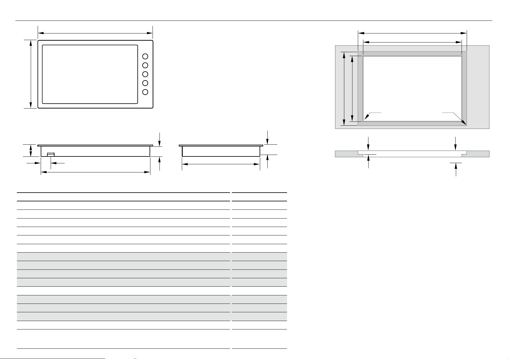
4 PRODUCT & CABINETRY DIMENSIONS
SIDE
TOP
FRONT
PRODUCT DIMENSIONS inches (mm)
Overall height of product (excluding burners, dials and pan supports) 3 1/8” (80)
A
Overall width of product 35 1/2” (900)
B
Overall depth of product 20 7/8” (530)
C
Height of chassis (below top of counter) 3 1/16” (77)
D
Width of chassis 33 13/16” (859)
E
Depth of chassis 19 3/16” (487)
F
Overall width of cutout 34 1/4” (870)
G
Overall depth of cutout 19 7/16” (494)
H
Corner radius of cutout max. 3/8” (10)
I
Distance from top of counter to center of gas inlet on product 2 15/16” (74)
J
Distance from edge of chassis to gas inlet on product 7/8” (22)
K
3
F
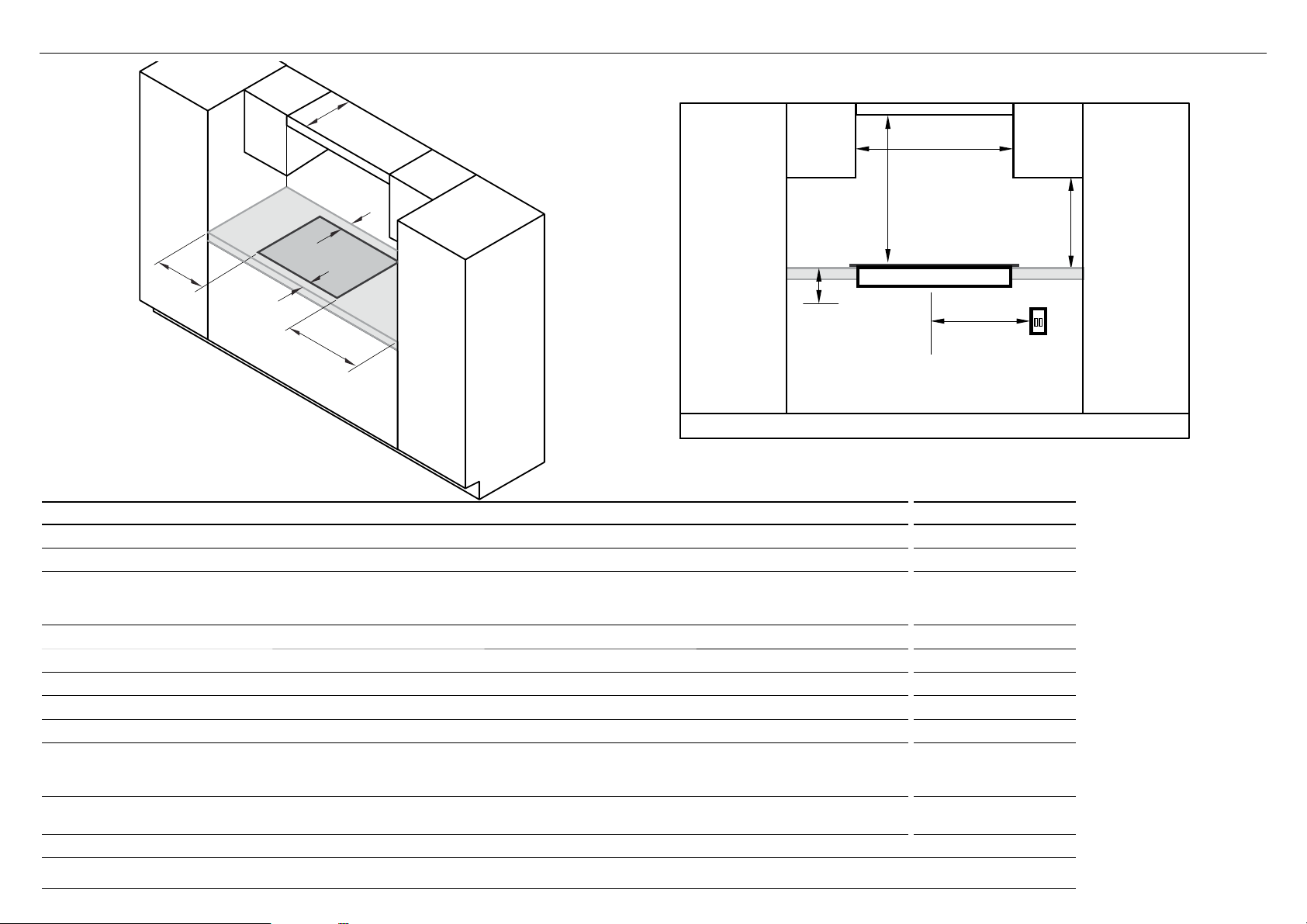
5 CLEARANCE DIMENSIONS
G
C
E
H
A
D
I
J
B
ISO
FRONT
CLEARANCE DIMENSIONS inches (mm)
Minimum clearance from left edge of product to nearest vertical surface 3 1/2” (90)
A
Minimum clearance from right edge of product to nearest vertical surface 1” (25)
B
Minimum clearance from rear edge of product to:
C
nearest combustible surface
nearest non-combustible surface*
Minimum clearance from front edge of counter to front edge of product 1 1/4” (32)
D
Minimum clearance from cooking surface to combustible surface centered above the cooking surface 34” (860)
E
Maximum overall depth of overhead cabinetry 13” (330)
F
Minimum distance between overhead cabinets installed to either side of productt 36” (915)
G
Minimum vertical distance between counter and cabinet extending above the counter 18” (457)
H
Minimum clearance below top of countertop to:
I
nearest combustible surface
F&P oven or nearest non-combustible surface
Maximum distance from the center of the product to the nearest grounded power outlet.
J
The power supply cable must not touch any hot metal surfaces.
less than 1 1/4” (32)
5 1/2” (140)
3 5/16” (84)
3 5/16” (84)
30” (762)
* Recommended non-combustible materials are: 1/4” (6 mm) flame retardant millboard covered with not less than No. 28 MSG sheet steel, 0.015” (0.4 mm) stainless steel,
0.024” (0.6 mm) aluminum or 0.020” (0.5 mm) copper.
4
A
M
D
B
E
C
F
L
5 FLUSH MOUNTING INSTALLATION (OPTIONAL)
IMPORTANT!
Refer to the NOTE in ‘Before you install
the appliance’ in the Safety and Warnings
section before you flush mount this
appliance.
HH
G
G
TOP
Note: Electrical
connection is
made at the right rear
REAR
PRODUCT AND CABINETRY DIMENSIONS inches (mm)
Overall height of product (excluding burners, dials and pan supports)
A
Overall width of product 35 1/2” (900)
B
Overall depth of product 20 7/8” (530)
C
Height of chassis (below top of counter)
D
Width of chassis
E
Depth of chassis
F
Overall width of routered recess
G
I
Width of cutout
G
Overall depth of routered recess
H
I
Depth of cutout
H
Corner radius of cutout
I
Corner radius of routered recess
J
Height of routered recess
K
Distance from top of counter to center of gas inlet on product 2 13/16” (71)
L
Distance from edge of chassis to gas inlet on product 7/8” (22)
M
Minimum clearance below top of benchtop to:
N
rear top of oven* installed below cooktop or cabinetry
thermal protection barrier
5
SIDE
33 13/16” (859)
3 1/8” (80)
3 1/16” (77)
19 3/16” (487)
35 5/8” (905)
34 1/4” (870)
21 1/16” (535)
19 7/16” (494)
max. 3/8” (10)
max. 3/16” (5)
1/8” (3)
3 1/2” (89)
3 1/2” (89)
IJ
TOP
K
FRONT
N
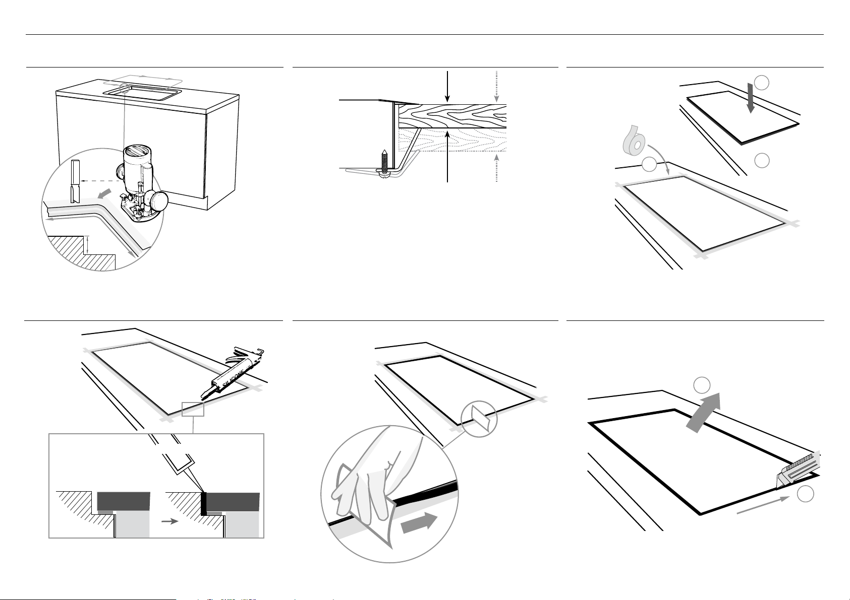
5 FLUSH MOUNTING INSTALLATION (OPTIONAL)
A ROUTER THE COUNTERTOP TO THE SPECIFIED DEPTH
1/8”
5 mm
(3 mm)
D APPLY SILICONE
B FIT THE CLAMPING BRACKETS
3/4” - 2”
(19 mm - 50 mm)
REPEAT ON ALL THE OTHER SIDES
(Total 6 brackets)
E WIPE OFF EXCESS SILICONE
C MASK OFF THE AREA TO BE SILICONED
1
3
F IF REMOVING PRODUCT, CUT
AROUND THE SILICONE
2
min. 150 OC rated
Ensure silicone does not leak underneath the steel edge.
TO REMOVE PRODUCT
2
1
6
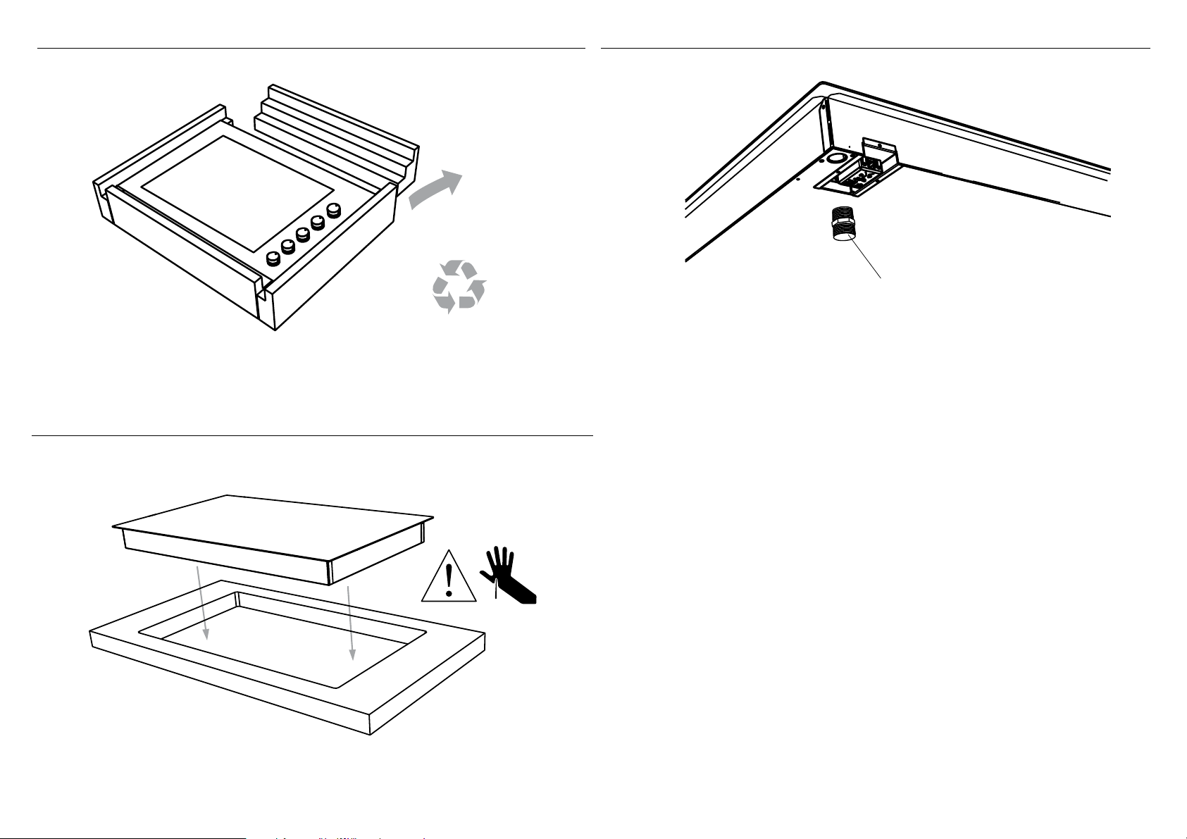
6 DISCARD PACKAGING 7 FIT THE NIPPLE AND WASHER
Model may vary from illustrations shown
8 LOWER GENTLY INTO THE CUTOUT
IMPORTANT! - Use gas tape
to seal the connection
Nipple (½” NPT thread)
Recycle responsibly
7

9 SECURE TO COUNTERTOP WITH BRACKETS BASED ON THE COUNTERTOP THICKNESS
on
Place the cooktop into the cutout and
tighten it with the supplied clamps. These
will cope with the countertop thicknesses
3/4”- 2” (19 - 50 mm)when used in the two
orientations shown.
REPEAT ON ALL THE OTHER SIDES
(Total 6 brackets)
IMPORTANT! - Do not over tighten.
3/4” - 2”
(19 mm - 50 mm)
!0 GAS CONNECTION
●
Make sure the connection point will be accessible with the cooktop installed.
●
To enable the gas supply to be readily shut off by the customer, make sure the connection is fitted with an isolating valve
close to the cooktop.
●
The appliance must be isolated from the gas supply piping system by closing its individual shut-off valve during any pressure testing of the
gas supply piping system at test pressures at or less than 1/2 p.s.i. (3.5 kPa).
●
Maximum inlet gas supply pressure 20” W.C. (5 kPa). Minimum gas supply pressure for regulator testing 5” W.C. Natural Gas / 12” W.C LP
gas.
●
A manual shut-off valve must be installed in an accessible location in the gas line external to the appliance for the purpose of turning on or
shutting off gas to the appliance. (In Massachusetts, such shut-off devices should be approved by the Board of State Examiners of Plumbers
& Gas Fitters).
●
Gas connection to the product must use the nipple supplied with a 1/2” NPT external thread. The supplied gas pressure regulator must be
installed where it will be accessible for adjustment. The metal flexible hose used must be new, CSA or UL-approved, and must have a 1/2”
NPT external thread on one end and a 1/2” NPT one on the other
If connecting the gas with a flexible hose
●
Ensure the hose is long enough to allow for removal of cooktop for servicing.
●
Make sure the connector is located as shown in step 5 CLEARANCE DIMENSIONS.
●
The hose assembly must be with an Rp 1/2” (ISO 7-1) female thread connection.
●
The hose assembly must be as short as practicable and comply with the relevant requirements.
●
The hose must not be kinked, subjected to abrasion or permanently deformed.
●
The hose must not be near or in contact with any hot surfaces (e.g. base of metal hotlplate, flue, or chassis of undercounter oven etc.)
8
 Loading...