


CP SERIES PROFESSIONAL GAS COOKTOP
Installation Guide
MODELS:
CP-366
CP-364GL
CP-364GD
CP-484GG
CP-485GD
CP-486GL
CP-486GD


A MESSAGE TO OUR CUSTOMERS
Thank you for selecting this DCS professional Cooktop. Because of this appliance’s unique features we have
developed this Installation Guide. It contains valuable information on how to properly install your new appliance
for years of safe and enjoyable cooking.
For your convenience, product questions can be answered by a DCS Customer Care Representative
by phone: 1-888-936-7872, ou email:
NOTE: Please write the Model, Code, and Serial Number on this page for references (located on the rating plate
behind the unit right side)
MODEL NUMBER SERIAL NUMBER
NOTE: Inspect the product to verify that there is no shipping damage. If any damage is detected, call the shipper
and initiate a damage claim. DCS by Fisher & Paykel is not responsible for shipping damage.
DO NOT discard any packing material (box, pallet, straps) until the unit has been inspected.
WARNING
Improper installation, adjustment alteration, service or maintenance can cause property damage, injury or death.
Read the installation, operating and maintenance instructions thoroughly before use, installing or servicing this
equipment.
customer.care@fisherpaykel.com
.
WARNING
If the information in this manual is not followed exactly, a fire or explosion may result causing property damage,
personal injury or death.
Do not store or use gasoline or other flammable vapors and liquids in the vicinity of this or any other appliance.
DANGER
If You Smell Gas:
1. Do not try to light any appliance.
2. Do not touch any electrical switch; do not use any phone in your building.
3. Immediately call your gas supplier from a neighbor’s phone. Follow the gas supplier’s instructions.
4. If you cannot reach your gas supplier, call the fire department.
5. Installation and service must be performed by a qualified installer, service agency or the gas supplier.
WARNING
To reduce the risk of injury to persons in the event of a cooktop grease fire, observe the following: Turn burner off
first. Smother flames with a close-fitting lid, cookie sheet, metal tray, baking soda or use a dry chemical or foam-type
fire extinguisher. Be careful to prevent burns. If the flames do not go out immediately evacuate and call the fire
department. Never pick up a flaming pan - You may be burned. DO NOT USE WATER ON GREASE FIRES, including
wet dishcloths or towels - a violent steam explosion will result. Use an extinguisher ONLY if:
1. You know you have a Class ABC extinguisher, and you already know how to operate it.
2. The fire is small and contained in the area where it started.
3. The fire department is being called.
4. You can fight the fire with your back to an exit.
PLEASE RETAIN THIS MANUAL FOR FUTURE REFERENCE.
1

TABLE OF CONTENTS
INTRODUCTION 3
SAFETY PRACTICES AND PRECAUTIONS 4-6
MODELS 7
PLANNING THE INSTALLATION 8-9
UNPACKING AND HANDLING 9-10
VENTILATION REQUIREMENTS 11
CABINET PREPARATION 12-14
BACKGUARD INSTALLATION 15
ELECTRICAL CONNECTIONS 15
GAS HOOK-UP 16
TEST AND ADJUSTMENTS 17
CLEANING EXTERIOR SURFACES 18
INSTALLER FINAL CHECKLIST 19
HOW TO OBTAIN SERVICE 20
WARRANTY 21-22
2

INTRODUCTION
The DCS Professional CP Cooktops feature a large number of features varying with each model. All models
feature a minimum of 4 surface burners, with the option of up to 6 surface burners on all models. All of the 48"
and 36" Cooktops feature the possibility of various grill and griddle combinations. All cooktop models require
the installation of one of the two offered backguards, if installed with less than 12” of clearance to combustible
material. See page 14.
IMPORTANT INSTALLATION INFORMATION
The cooktops are tested in accordance with ANSI Z21.1 Standard for Household Cooking Gas Appliances. These
cooktops must be installed in conjunction with a suitable overhead vent hood. (See ventilation requirements).
Due to the professional high heat capacity of this unit, particular attention should be paid to the hood and duct
work installation to ensure it meets local building codes. To eliminate risk of burns or fire by reaching over
heated surface units, cabinet storage located above the surface units should be avoided.
Check local building codes for the proper method of cooktop installation. Local codes vary. Installation,
electrical connections, and grounding must comply with all applicable codes. In the absence of local codes, the
cooktop should be installed accordance with the National Fuel Gas Code ANSI Z223.1 and National Electrical
Code ANSI / NFPA 70. Be sure that the unit being installed is set up for the kind of gas being used. The gas
cooktop is shipped from the factory set and adjusted for natural gas or LP (propane), depending on the specific
model ordered. Verify that the cooktop is compatible with gas supply at the installation site before
proceeding further. Return cooktop to dealer if unit is not set for site gas supply.
3

SAFETY PRACTICES AND PRECAUTIONS
When properly cared for, your new DCS Appliance has been designed to be a safe, reliable cooking appliance.
When using this restaurant caliber appliance, use it with extreme care, as this type appliance provides intense
heat and can increase the accident potential. Basic safety precautions must be followed when using kitchen
appliances, including the following:
■
Read the Use and Care Manual, which came with this appliance, thoroughly before using your new appliance.
This will help to reduce the risk of fire, electric shock, or injury to persons.
■
Begin by insuring proper installation and servicing. Follow the installation instructions in this manual. Be sure to
have a qualified technician install and ground this appliance before using.
■
Have the installer show you where the gas supply shut-off valve is located so you will know how and where to
turn off the gas to the appliance.
■
If you smell gas, the installer has not done a proper job of checking for leaks. You can have a small leak and
therefore a faint gas smell if the connections are not completely tight. Finding a gas leak is not a “do-it-yourself”
procedure. Some leaks can only be found with the burner control in the ON position and for your protection it
must be done by a qualified service technician.
■
If by some chance a burner goes out and gas escapes, open a window or a door to let the room air out. Do not
attempt to use the appliance until the gas has had time to dissipate. Follow the instructions on page 1, “For your
safety – if you smell gas”.
■
This appliance has been factory assembled for natural or LP gas. It should be correctly adjusted from the factory
for the type of gas that is used.
■
Do not repair or replace any part of this appliance unless it is specifically recommended in this manual. All other
servicing should be referred to a qualified technician.
■
Children should not be left alone or unattended in an area where appliances are in use. They should never be
allowed to turn knobs, push buttons, sit or stand on any part of an appliance while in operation.
WARNING:
Do not store items of interest to children above or at the back of any appliance. Children could be seriously injured
if they should climb onto the appliance to reach these items.
■
Never store anything on the cooktop. Flammable materials can catch fire, plastic items may melt or ignite and
other types of items could be ruined.
■
Do not hang articles from any part of the appliance or place anything against the oven. Some fabrics are quite
flammable and may catch on fire.
■
If the appliance is near a window be certain the curtains do not blow over or near the cooktop burners; they
could catch on fire.
■
Do not use water on grease fires. Turn all burners OFF, then smother fire with baking soda or use a dry chemical
or foam-type fire extinguisher.
■
Never let clothing, pot holders, or other flammable materials come in contact with, or too close to, any burner or
burner grate until it has cooled. Fabric may ignite and result in personal injury.
■
Be certain to use only dry pot holders: moist or damp pot holders on hot surfaces may cause burns from steam.
Do not use a towel or other bulky cloth in place of pot holders. Do not let pot holders touch hot burners, or
burner grates.
■
For personal safety, wear proper apparel. Loose fitting garments or hanging sleeves should never be worn while
using this appliance. Some synthetic fabrics are highly flammable and should not be worn while cooking.
4

SAFETY PRACTICES AND PRECAUTIONS
■ Do not use aluminum foil to line any part of the cooktop. Doing so, heat will be trapped underneath it. This
trapped heat can upset the cooking performance and can damage the finish of the cooktop parts.
■ This appliance is for cooking. Never use the cooktop to warm or heat a room. This could damage the cooktop.
WARNING! NEVER use this appliance as a space heater to heat or warm the room.
Doing so may result in carbon monoxide poisoning.
■
When using the cooktop: Do not touch the burner grates or the immediate surrounding area. Areas adjacent to
the burners may become hot enough to cause burns.
■
Never leave the cooktop unattended when using high flame settings. When cooking with high flame settings,
boil overs may cause smoking and greasy spill overs may ignite. More importantly, if the burner flames are
smothered by a severe boil over which effects the igniter, unburned gas will escape into the room.
■
Only certain types of glass, heat-proof glass-ceramic, ceramic, earthen ware, or other glazes utensils are suitable
for cooktop use. This type of utensil may break with sudden temperature changes. Use only on low or medium
flames settings according to the manufacturer’s directions. The use of professional utensils is recommended.
■
Do not heat unopened food containers; a build up of pressure may cause the container to burst.
■
During cooking, set the burner control so that the flame heats only the bottom of the pan and does not extend
beyond the bottom of the pan. This could heat and/or melt the handles, and may increase cooking time.
■
Always use utensils that have flat bottoms large enough to cover the burner. The use of undersized utensils will
expose a portion of the flame to direct contact and may result in ignition of clothing.
■
To minimize burns, ignition of flammable materials and unintentional spill overs, position handles of utensils
inward so they do not extend over adjacent work areas, cooking areas, or the edge of the cooktop.
■
Hold the handle of the pan to prevent movement of the utensil when stirring or turning food.
■
Grease is flammable. Let hot grease cool before attempting to handle it. Avoid letting grease deposits collect
around the cooktop burners. Clean after each use or boil over.
■
For proper lighting and performance of the cooktop burners, keep the burner ports clean. It may be necessary to
clean these when there is a boil over or when the burner does not light, even though the electronic igniters
click.
■
Do not use the grill for cooking excessively fatty meats or products which promote flare-ups. Do not use
cooking utensils on the grill.
5
SAFETY PRACTICES AND PRECAUTIONS
Installer supplied shut-off valve
must be easily accessible inside
cabinetry.
Gas Supply
■
Clean the cooktop with caution. Avoid steam burns; do not use a wet sponge or cloth to clean the cooktop
while it is hot. Some cleaners produce noxious fumes if applied to a hot surface. Follow directions provided by
the cleaner manufacturer.
■
Be sure all the cooktop controls are turned off and the appliance is cool before using any type of aerosol cleaner
on or around the appliance. The chemical that produces the spraying action could, in the presence of heat,
ignite or cause metal parts to corrode.
■
Clean the ventilator hood and filters above the cooktop frequently so grease from cooking vapors does not
accumulate on them.
■
Turn the ventilator OFF in case of fire or when intentionally “flaming” liquor or other spirits on the cooktop. The
blower, if in operation, could unsafely spread the flames.
■
DO NOT obstruct the flow of combustion or ventilation air to the appliance. Be sure a fresh air supply is
available.
■
For safety reasons and to avoid damage to the appliance never sit, stand, or lean on the cooking surface.
■
Service should only be done by authorized technicians. Technicians must disconnect the power supply before
servicing this appliance.
WARNING:
California Proposition 65 - The burning of gas cooking fuel generates some by-products which are known by the
State of California to cause cancer or reproductive harm. California law requires businesses to warn customers of
potential exposure to such substances. To minimize exposure to these substances, always operate this unit
according to the instructions contained in this booklet and provide good ventilation to the room when cooking with
gas.
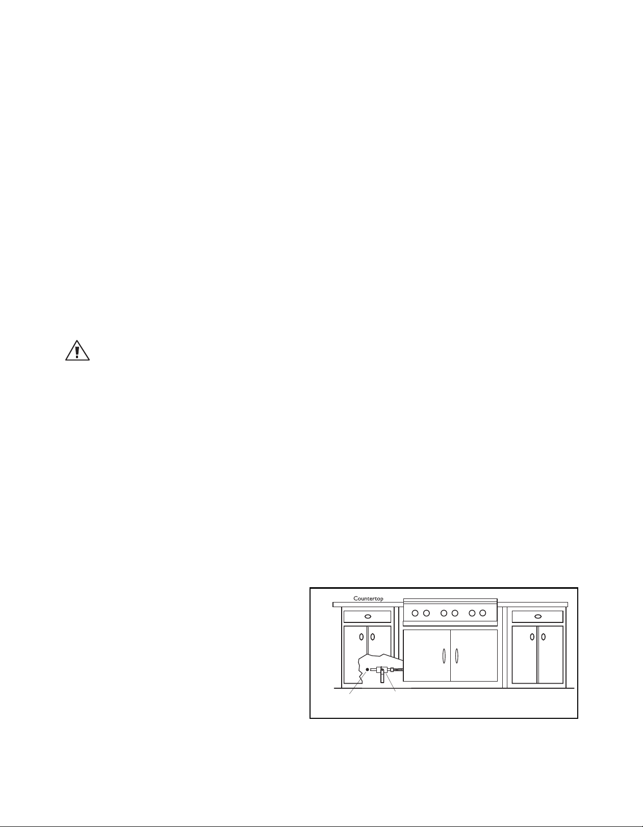
RECOMMENDATIONS ON HOOK-UP TO GAS SUPPLY:
A manual valve must be installed external to the appliance, in an accessible location from the front for the
purpose of shutting off the gas supply. The supply line must not protrude beyond the back of the unit. Make
sure the gas supply is turned off at the wall valve before connecting the appliance.
The gas supply connections should be made by a qualified technician and in accordance with local codes or
ordinances. In the absence of a local code, the installation must conform to the latest edition of National Fuel
Gas Code ANSI Z223.1.
NOTE:
This product must be installed by a licensed plumber or gas fitter when installed within the Commonwealth of
Massachusetts.
NOTE:
(mandatory for the State of Massachusetts)
Alternate method of supplying gas must be installed
into the unit.
6

MODELS
48” CP COOKTOP MODELS
CP-484GG
CP-485GD
36” CP COOKTOP MODELS
CP-366
CP-486GL CP-486GD
CP-364GL CP-364GD
7

PLANNING THE INSTALLATION
IMPORTANT INSTALLATION INFORMATION
All cooktop models with less than a 12” clearance between combustable material and the back edge of the
cooktop, require the installation of one of the two offered Wall Mount Backguards – see page 15.
Wall Mount Full
Backguard
15/16”
Wall Mount
Low Backguard
15/16”
FIG. 1
12”
30”
Model Number
Low
Backguard
48” Cooktop BGC-1248 BGC-3048
36” Cooktop BGC-1236 BGC-3036
Full
Backguard
8

PLANNING THE INSTALLATION
RECOMMENDED INSTALLATION INSTRUCTION
Install components in the following order:
A. Vent Hood
B. Backguard System (sold separately)
C. Cooktop
1. Locate cooktop according to cooktop installation instructions.
2. Measure distance from counter surface to top of trim on cooktop adding 1/8” for backguard clearance.
3. Transfer this measurement to the wall. This will mark the bottom of your backguard.
4. From this line measure 30-1/16” up wall to mark top of 30” backguard. This is the minimum height that the
bottom of your vent hood can be installed.
5. Follow vent hood manufacturer’s installation instructions to install vent hood.
6. Follow backguard installation instructions to install backguard.
7. Connect gas and electric connections and slide cooktop into position.
NOTE:
A manual gas supply valve must be installed. See page 16.
UNPACKING AND HANDLING
CAUTION:
Proper equipment and adequate manpower must be used in moving the cooktop to avoid personal injury or
damage to the unit.
MOVING AND PLACING THE COOKTOP
The cooktops have a shipping weight of approximately 228 pounds (36" models) and 324 pounds (48" models).
After removal of packing materials, it is recommended that the grates and drip pan (below knobs) be removed to
facilitate handling. This will reduce the weight to about 150 pounds.
■
DO NOT REMOVE THE GRILL OR GRIDDLE ASSEMBLIES.
NOTE:
If a solid side cabinet wall exists on one or both sides, you will need to notch the front corner of the cabinet to match the
counter top notch and to provide clearance for the cooktop front (see page 14).
It may be necessary to remove the cooktop knobs to pass through some doorways. With the knobs removed a
29-3/8" wide opening is required. Remove the outer carton and packing material from the shipping base. The
cooktop is held to the skid by four straps. After removing the straps, the cooktop must be lifted and removed
from the skid.
9
UNPACKING AND HANDLING
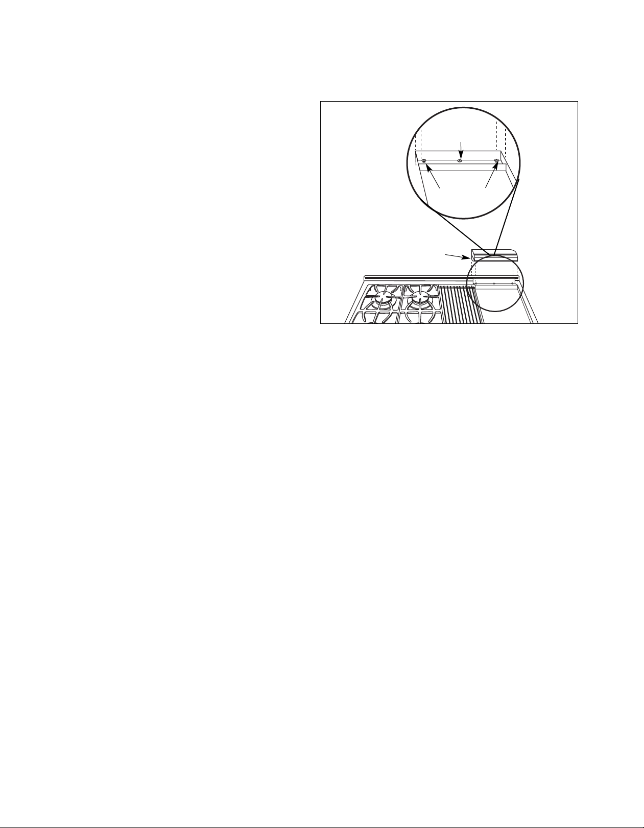
■
The professional cooktop should be moved close to
its final location. Electric and gas connections should
be made (pgs. 15 & 16) and the backguard installed
(as required, pg. 8 & 15) before the cooktop is placed
in its final position. The grill and griddle sections are
fastened in place at the front with screws. They are
designed to be stationary and not meant to be
removed for cleaning. The griddle has two leveling
screws beneath the rear flue cover which can be used
to adjust the griddle to the desired slope. The center
screw is for shipping and should be removed. See Fig.
2.
ANCHORING THE COOKTOP
■
Due to the weight of the cooktop, along with a builtin side frame gasket that is meant to rest and create
a seal on the counter top once installed, it is not
necessary to anchor the unit to the counter.
Shipping Screw
(remove)
Outer Leveling
Screws (2)
Griddle Flue Cover
Fig. 2
10

VENTILATION REQUIREMENTS
A suitable exhaust hood must be installed above the range. The following chart indicates the minimum blower
capacity recommended for hood ventilation.
Standard Counter
Ventilation Unit
Installation
Recommendatons
HOOD 24" Deep x Unit Width 30" Deep x 36" at Bottom
48” Cooktop
BLOWER
* When installing a unit featuring a grill, GL models, requires a 1200 CFM ventilation unit.
1200 CFM
*36” Cooktop
600-1200 CFM
Island Installation
Recommendatons
1200 CFM
600-1200 CFM
CAUTION:
Ventilation hoods and blowers are designed for use with single wall ducting. However, some local building codes or
inspectors may require double wall ducting and/or damper. Consult local building codes and/or local agencies,
before starting, to ensure that hood and duct installation will meet local requirements.
Hood blower speeds should be variable to reduce noise and loss of heated or air conditioned household air
when maximum ventilation is not required. Normally, the maximum blower speed is only required when using
the grill.
For best smoke elimination, the lower edge of the hood should be installed a minimum of 30" to a maximum of
36" above the cooktop cooking surface, (page 12). If the hood contains any combustible materials (i.e. a wood
covering) it must be a minimum of 36" above the cooking surface.
Due to a high volume of ventilation air, a source of make-up air (outside replacement air) is recommended. This
is particularly important for tightly sealed and insulated homes. A reputable heating and ventilating contractor
should be consulted.
11

CABINET PREPARATION
G
H
F
D
E
Min. 48" Wide Hood
Min. 36" Wide Hood
J
16"
Electrical and
Gas Supply.
2"
13"
Max.
12" Min. to
Combustible
Material#,
Each Side
CAUTION
36" Min. to
combustible
material#, from
cooking surface
Cooking Surface
2" x 4" corner
support (ifrequired )
18" Min.
A
C
B
# As defined in the “National Fuel Gas Code” (ANSI Z223.1, lastest edition).
The horizontal surfaces of the cooktop trim must not be below
countertop level.
30" Min.
36" Max.
for best smoke
elimination
1. To ensure professional results, the cabinet and countertop openings should be prepared by a qualified cabinet
worker. We recommend having the cooktop available before cutting the opening for more precise dimension
verification.
2. The clearances shown in Fig. 8 pg. 14 are required for all types of backguard installations.
3. The cooktop is designed to hang from the countertop from its rear and side flanges. The countertop, however,
must be strong enough to support this heavy cooktop. It may be necessary to add a supporting cleat along each
side or another form of support such as a 2” x 4” corner brace on each side, or a deck to set the cooktop on.
See Fig. 3 & 5.
4. The cooktop can be installed in various positions with the front either flush or projecting, depending on the
countertop depth. See Fig. 4 & Fig. 7 (cooktop side view).
5. Establish the centerline of the desired cooktop location. It should be the same as the center of the overhead
ventilation hood.
12
Fig. 3
Models ABCDEFGHJ
CP-48 Models 47-7/8” 26-1/2” 8-7/16” 46-15/16” 22-3/4” 8” 7/8” 0 ~ 2-1/2” 17”
CP-36 Models 35-7/8” 26-1/2 ” 8-7/16 ” 34-15/16” 22-3/4” 8” 1/2” 0 ~ 2-1/2” 7”

CABINET PREPARATION
Flush with cabinets
Front projects outward as shown
from standard depth cabinet.
Front flush with cabinets; a minimum
of 25
3/4" cabinet depth required
Counter-Sunk Screws
6. Cut the openings for the following installation:
■ Standard counter top installation, see Fig. 8A
■ Deep counter or island installation, see Fig. 8B
NOTE:
If the deck is used, the sides or bottom of the cutout may be solid
combustible or non-combustible material. If the bottom is solid, provide
a 6" x 6" cutout in the left rear corner for the gas inlet and power cord
clearance. See Fig. 6.
Front projects outward as shown
from standard depth cabinet.
Flush with cabinets
Counter-Sunk Screws
Front flush with cabinets; a minimum of 25-3/4”
cabinet depth required
Fig. 4
Cutout
6
6
Fig. 5
Fig. 6
13

CABINET PREPARATION
8-7/16"
22-3/4"
26-1/2"
23-1/4"
3" To Center Line
of Gas Inlet
1/2"
1/2"
5/8"
Cabinet face for installation
with projecting control panel
Cabinet face for installation
with flush control panel
2-1/2"
Countertop level
#
30"
26-1/2"
12" Min. to Combustibles
#
without Backguard
15/16"
12"
Wall Mount
Low Backguard
Base Cabinet
Wall Mount
Full Backguard
36” Min. to
Combustibles
#
36” Min. to
Combustibles
#
#
As defined in the “National Fuel Gas Code” (ANSI Z223.1, lastest edition).
A B
Fig. 7
14
Fig. 8

Receptacle Box
Cover Plate
Three Prong
Receptacle
Three
Prong
Plug
BACKGUARD INSTALLATION
12"
30"
15/16"
The backguard is located as shown in Fig. 9. Secure the
backguard to the wall behind the range. Specific
instructions for installation of the full backguard or low
backguard can be found packaged with the backguard.
See also page 8, “Planning The Installation” section. A
backguard must be installed when there is less than a
12” clearance between combustibles and the back of
the range (above the cooking surface). See fig. 8.
DCS backguards are sold separately.
Wall Mount
Full Backguard
(Model #’s BGC-3036, BGC-3048)
Wall Mount
Low Backguard
(Model #’s BGC-1236, BGC-1248)
Fig. 9
ELECTRICAL CONNECTIONS
ELECTRICAL REQUIREMENTS
■
120 VAC, 60 Hz., single phase
■
CP-48: 15 Amp. Max. (use 15 Amp. circuit)
■
CP-36: 15 Amp. Max. (use 15 Amp. circuit)
Always disconnect electric supply cord from the wall outlet or service
disconnect before servicing this appliance. Observe all governing codes
and ordinances when grounding, in absence of which, observe National
Electrical Code ANSI / NFPA No. 70.
RECOMMENDED GROUNDING METHOD
This appliance is factory equipped with a power supply cord with a
three-prong grounding plug (with polarized parallel blades). It must be
plugged into a mating grounding type receptacle, connected to a
correctly polarized 120 Volt circuit. If the circuit does not have a
grounding type receptacle, it is the responsibility and obligation of the
installer to have the existing receptacle changed to a properly grounded and polarized receptacle in accordance
with all applicable local codes and ordinances by a qualified electrician. In the absence of local codes and
ordinances, the receptacle replacement shall be in accordance with the National Electrical Code.
Note:
The third prong should not, under ANY circumstances, be cut or removed.
Fig. 10
15

GAS HOOK-UP
*Installation must conform with
local codes or with the National
Fuel Gas Code ANSI Z223.1 or
the CAN/CGA-B149.2 Propane
Installation Code
Coupling
1/2 NPT black
1/2 NPT
Close Nipple
Regulator
LP/NG (included)
Adapter 1/2 NPT
to 3/8 flare fitting
Do not put threading
compound on these
threads
Bottom of unit
Threading compound
must be resistant to LP gas
1/2 x 5" NPT
Close
Nipple
Installer supplied shut-off
valve must be easily
accessible*
Flex Line to Cooktop
Manual Shut-Off
Valve must be
Easily Accessible
!
GAS REQUIREMENTS
Verify the type of gas supplied to the location. The cooktop is shipped from the factory set up and adjusted for
Natural Gas or LP (propane), depending on the specific model ordered.
with gas supply at the installation site before proceeding further.
not set for the gas supplied at the site.
NATURAL GAS
■ Connection: 1/2” NPT Minimum 5/8” dia. flex line. ■ Supply Pressure: 6” to 14” W.C.
LP GAS
■ Connection: 1/2” NPT Minimum 5/8 dia. flex line. ■ Supply Pressure: 11” to 14” W.C.
A regulator is required at the LP source to provide a maximum of 14” W.C. to the cooktop regulator.
HOOK-UP TO GAS SUPPLY
A manual valve must be installed external to the appliance, in an
accessible location from the front for the purpose of shutting off the
gas supply (Fig. 11). Make sure the gas supply is turned off at the
wall valve before connecting the appliance. The gas supply
connections should be made by a qualified technician and in
accordance with local codes or ordinances. In the absence of a local
code, the installation must conform to the latest edition of National
Fuel Gas Code ANSI Z223.1.
Verify that the cooktop is compatible
Return the cooktop to the dealer if the unit is
To prepare the unit for connection to the gas supply, thread the
supplied 1/2” pipe nipple into the elbow on the end of the manifold.
The elbow is located inside the chassis of the unit, on the end of the
manifold, facing down. See fig.12. It is accessible through the
square cutout in the left rear corner of the chassis bottom. Connect
the outlet of the regulator to the exposed end of the nipple, connect
the flex line from the gas supply to the inlet side of the regulator.
NOTE:
Pipe seals must be used on all pipe threads.
CAUTION:
The appliance must be isolated from the building’s gas
supply piping system by closing its individual manual
shut-off valve during any pressure testing of the gas
supply piping system at test pressures equal to or less
than 1/2 psig (3.5kPa.). The appliance and its
individual shut-off valve must be disconnected from
the gas supply piping system during any pressure
testing of the system at the test pressures in excess of
1/2 psig (3.5kPa.). When checking the manifold gas
pressure, the inlet pressure to the regulator should be
at least 7.0”W.C. for natural gas or 12.0”for LP.
NOTE:
The arrow on the regulator indicating direction of gas
flow should be pointing towards the unit. The flex line
for the gas supply must be metal and be approved by an
approved certifying agency (AGA, CGA, or UL). Never use
a hose made of rubber or other synthetic material, as the
heat may cause the hose to melt and develop leaks.
Fig. 11
Fig. 12
16

TEST AND ADJUSTMENTS
1-1/2"
1-1/2" ~ 2"
Typical Section of Proper Flame
3/8" ~ 5/8"
(Grill)
(Griddle)
WARNING:
COOKTOP BURNER
For warranty coverage, DCS requires that burner adjustments be made by a
qualified technician at the time of installation. Extreme care should be used
when adjustments are made after installation.
COOKTOP BURNERS
The cooktop burners are not adjustable. Proper operation is achieved when
the correct orifices for gas supply are installed at the factory, based on model
ordered.
When installing the burner port ring, be sure that the two locating pins in the
bottom side of the brass port ring are properly aligned with the locating notch
and center holes on the top side of the simmer ring. Incorrect alignment will
produce a potentially dangerous flame and poor burner performance.
Note:
No air shutter adjustment is possible on the cooktop burners. Burner flames should
be blue and stable with no yellow-tipping (some yellow-tipping is normal with LP
gas), excessive noise, or lifting of flame from the burner (Fig. 13).
SIM
FIG. 13
OFF
LITE
HI
LO
FIG. 14
COOKTOP BURNER LIGHTING NOTE
The cooktop burners have an infinite number of heat settings and there are no fixed positions on the control
knobs between HI and LO. To turn the cooktop burner on, push in on the control knob and turn it counterclockwise to the “LITE” position. An audible clicking sound will be heard. When the gas has been ignited by the
electronic spark igniter, turn the knob to the desired setting (Fig. 14).
Note:
The igniter will continue to click until a flame is present. If the cooktop burner
does not ignite, check the spark igniter by listening for a clicking sound. If you
do not hear the igniter click, turn off the burner. Check for a tripped circuit
breaker, blown fuse, or poor wire connection to the igniter.
WARNING:
When turning on any cooktop burner, be sure to stop at the “LITE” position
before turning the burner to a flame setting for cooking. If the burner is not
lit and it is turned beyond the “LITE” position, to HI, MEDIUM, or LO, there
will be a burst of flame when the burner does light. This could cause burns
or damage to the surrounding countertop.
THIS ADJUSTMENT SECTION APPLIES TO THE GRIDDLE
AND GRILL BURNERS.
Check for the proper burner flame characteristics and adjust air shutters if
necessary (fig. 15). Each valve and air shutter is individually tested and
adjusted prior to shipment. Normally adjustment is not required,
however, vibration during transit, gas conversion or variations in the local
gas supply may make minor adjustments necessary. Burner flames should
be blue and stable with no yellow tips, excessive noise or lifting of the
flame from the burner. If any of these conditions exist, check that the air
shutter or burner ports are not blocked. If this condition persists, adjust
the air shutter as required. If the flame is too yellow, indicating insufficient air, adjust the shutter counterclockwise to increase air inlet. If the flame is noisy or tends to lift away from the burner, indicating too much air,
turn the shutter clockwise to reduce air. The griddle flames should be 1-1/2" to 2". The grill burner flames
should be 3/8” to 5/8” (fig. 16).
air shutter
Fig. 15
Typical Section of Proper Flame
Griddle
1-1/2” – 2”
Fig. 16
3/8” – 5/8”
Grill
17

CLEANING EXTERIOR SURFACES
The stainless steel surfaces may be cleaned by wiping with a damp soapy cloth or sponge. Any liquid soap (like
Dawn or Stainless Steel Magic) will remove fingerprints and smears. Do not use steel wool as it will scratch this
surface.
18

INSTALLER FINAL CHECKLIST
GENERAL
❑
Placement of unit.
❑
Specified clearance maintained to cabinet surfaces.
❑
Unit Level - front to back, side to side.
❑
All packaging material and tie straps removed, drip pans clean and empty.
❑
Backguard attached if there is less than 12" clearance above the cooking surface to combustibles behind unit.
❑
Radiant tray placed in grill unit (if equipped). The two grill racks in place.
ELECTRICAL
❑
Receptacle with 15 ampere over-current protection is provided for service cord connection.
❑
Adequate ground connection.
GAS SUPPLY
❑
Connection: 1/2 NPT with a minimum 5/8" diameter flex line. Site gas supply is compatible with range model,
and sufficient pressure is available (see gas requirements pg. 16).
❑
The pressure regulator which is connected to the manifold is set for 5.0” W.C. for natural gas or 10.0”W.C. for LP.
❑
Manual gas shut-off valve installed in an accessible location.
❑
Unit tested and free of gas leaks.
OPERATION
❑
All internal packing materials removed. Check below grate, pans and drip drawers.
❑
If used on LP gas, verify that pressure regulator, orifice hoods, air shutters, and valve jets have been set for use
with LP gas.
❑
Grill compartment seated and does not rock (if equipped).
❑
Bezels centered on burner knobs and knobs turn freely.
❑
Each burner lights satisfactorily, both individually and with other burners operating at the same time.
❑
Flame adjustment for 3/8” soft blue cone made on ports of each top burner, low flame adjustment verified.
❑
Griddle is level and does not rock (if equipped).
❑
Drip trays are properly in place and pull out freely (if equipped).
❑
Burner grates correctly positioned, level, and do not rock.
❑
Griddle flame (see page 17).
❑
Grill flame (see page 17).
❑
Cooktop burner flame (see page 17).
19

HOW TO OBTAIN SERVICE
For warranty service, please contact DCS Customer Care Representative at (888) 936-7872. Before you call, please
have the following information ready:
■
Model Number (located on the rating plate behind the unit right side)
■
Serial Number (located on the rating plate behind the unit right side)
■
Date of installation
■
A brief description of the problem
Your satisfaction is of the utmost importance to us. If a problem cannot be resolved to your satisfaction, please
write to Customer Care or email:
Write:
Fisher & Paykel Appliances, Inc.
Attention: DCS Customer Care
5900 Skylab Road
Huntington Beach, CA 92647
BEFORE YOU CALL FOR SERVICE:
1. Is the circuit breaker tripped or the fuse blown?
2. Is there a power outage in the area?
customer.care@fisherpaykel.com
20

WARRANTY
LIMITED WARRANTY
When you purchase a new DCS Professional Cooktop you automatically receive a One Year Limited Warranty
covering parts and labor for the entire product, a Five Year Limited Warranty on surface burners, griddle burners
and grill burners (parts only) for servicing within the 48 mainland United States, Hawaii, Washington D.C. and
Canada. In Alaska the Limited Warranty is the same except that you must pay to ship the Product to the service
shop or the service technician’s travel to your home. Products for use in Canada must be purchased through the
Canadian distribution channel to ensure regulatory compliance.
FISHER & PAYKEL UNDERTAKES TO:
Repair without cost to the owner either for material or labor any part of the Product, the serial number of which
appears on the Product, which is found to be defective. In Alaska, you must pay to ship the Product to the
service shop or for the service technician’s travel to your home.
If we are unable to repair a defective part of the Product after a reasonable number of attempts, at our option
we may replace the part or the Product, or we may provide you a full refund of the purchase price of the Product
(not including installation or other charges).
This warranty extends to the original purchaser and any succeeding owner of the Product for products purchased
for ordinary single-family home use. All service under this Limited Warranty shall be provided by Fisher & Paykel
or its Authorized DCS Service Agent during normal business hours.
HOW LONG DOES THIS LIMITED WARRANTY LAST?
Our liability under this Limited Warranty for the entire product expires One Year from the date of purchase of the
Product by the first consumer. Our liability under this Limited Warranty for surface burners, griddle burners, and
grill burner (parts only) expires Five Years from the date of the purchase of the Product by the first customer.
Our liability under any implied warranties, including the implied warranty of merchantability (an unwritten
warranty that the Product is fit for ordinary use) also expires One Year (or such longer period as required by
applicable law) from the date of purchase of the Product by the first consumer. Some states do not allow
limitations on how long an implied warranty lasts, so this limit on implied warranties may not apply to you.
THIS WARRANTY DOES NOT COVER:
A. Service calls that are not related to any defect in the Product. The cost of a service call will be charged if the
problem is not found to be a defect of the Product. For example:
1. Correct faulty installation of the Product.
2. Instruct you how to use the Product.
3. Replace house fuses, reset circuit breakers, correct house wiring or plumbing, or replace light bulbs.
4. Correct fault(s) caused by the user.
5. Change the set-up of the Product.
6. Unauthorized modifications of the Product.
7. Noise or vibration that is considered normal, for example, drain/fan sounds, regeneration noises or user
warning beeps.
8. Correcting damage caused by pests, for example, rats, cockroaches etc.
21

WARRANTY
B. Defects caused by factors other than:
1. Normal domestic use or
2. Use in accordance with the Product’s User Guide.
C. Defects to the Product caused by accident, neglect, misuse, fire, flood or Act of God.
D. The cost of repairs carried out by non-authorized repairers or the cost of correcting such unauthorized repairs.
E. Travel Fees and associated charges incurred when the product is installed in a location with limited or restricted
access. (i.e. airplane flights, ferry charges, isolated geographic areas).
F. Normal recommended maintenance as set forth in the Product’s User Guide.
If you have an installation problem contact your dealer or installer. You are responsible for providing adequate
electrical, exhausting and other connection facilities.
We are not responsible for consequential or incidental damages (the cost of repairing or replacing other
property damaged if the Product is defective or any of your expenses caused if the Product is defective). Some
states do not allow the exclusion or limitation of incidental or consequential damages, so the above limitation or
exclusion may not apply to you.
HOW TO GET SERVICE
Please read your User Guide. If you then have any questions about operating the Product, need the name of your
local DCS Authorized Service Agent, or believe the Product is
defective and wish service under this Limited Warranty, please contact your dealer or call us at:
TOLL FREE 1-888-936-7872 or contact us through our web site: www.dcsappliances.com
You may be required to provide reasonable proof of the date of purchase of the Product before the Product will
be serviced under this Limited Warranty.
COMMERCIAL USE
This warranty applies to appliances used in residential applications; it does not cover their use in commercial
situations.
NO OTHER WARRANTIES
This Limited Warranty is the complete and exclusive agreement between you and Fisher & Paykel Appliances Inc.
regarding any defect in the Product. None of our employees (or our Authorized Service Agents) are authorised to
make any addition or modification to this Limited Warranty.
Warrantor: Fisher & Paykel Appliances, Inc.
If you need further help concerning this Limited Warranty, please call us at the above number, or write to:
Fisher & Paykel Appliances, Inc.
5900 Skylab Road, Huntington Beach, CA 92647
This Limited Warranty gives you specific legal rights, and you may also have other rights which vary from state to
state.
Fisher & Paykel Appliances Inc. is a leading manufacturer of premium quality cooking and specialty appliances
under the Fisher & Paykel and DCS brands.
22

NOTE
23

NOTE
24

TABLE DE CUISSON À GAZ PROFESSIONNELLE
DE SÉRIE CP
Guide d'installation
MODÈLES :
CP-366
CP-364GL
CP-364GD
CP-484GG
CP-485GD
CP-486GL
CP-486GD

À L'INTENTION DE NOS CLIENTS
Nous vous remercions d'avoir choisi cette cuisinière à gaz professionnelle DCS. Nous avons conçu ce Manuel
d'installation pour expliquer ses fonctions uniques. Il contient des informations extrêmement utiles sur la façon
d'installer correctement votre nouvel appareil. Vous pourrez ainsi en profiter pendant des années en toute
sécurité.
Si vous avez des questions au sujet de notre produit, communiquez avec un représentant du centre de service à
la clientèle DCS par téléphone :1-888-936-7872, ou par courriel :
REMARQUE : Veuillez noter les numéros de modèle et de série sur cette page pour information(situé sur la plaque
signalétique, sur le panneau arrière et également sur le cadre avant, coin inférieur droit entre le panneau de seuil
de porte et la porte du four).
NUMÉRO DE MODÈLE NUMÉRO DE SÉRIE
REMARQUE : Inspecter le produit pour vérifier qu’il n’a pas été endommagé pendant l’expédition. En cas de
dommages, contacter le transporteur et entamer une déclaration pour dommage. DCS by Fisher & Paykel n’est en
aucun cas responsable des dommages pendant l’expédition.
Ne pas jeter le matériau d’emballage (boîte, palette, sangles) avant d’avoir inspecté l’unité.
AVERTISSEMENT!
Toute installation, ajustement, altération ou entretien incorrect peut causer des dommages matériels, des blessures
ou la mort. Veuillez lire soigneusement ces instructions d'installation, d'utilisation et d'entretien avant d'installer,
utiliser ou effectuer l'entretien de cet appareil.
customer.care@fisherpaykel.com
.
AVERTISSEMENT!
Si les informations de ce manuel ne sont pas suivies à la lettre, un incendie ou une explosion peuvent se produire et
causer des dommages matériels, des blessures ou la mort.
Évitez de stocker ou d'utiliser de l'essence ou tout autre liquide et vapeur inflammable à proximité de cet appareil
électroménager ou de tout autre.
DANGER
Si vous sentez une odeur de gaz :
1. N'essayez pas d'allumer aucun appareil électroménager.
2. Ne touchez aucun interrupteur électrique; n'utilisez aucun téléphone dans l'édifice.
3. Appelez immédiatement votre fournisseur de gaz de chez un voisin. Suivez les instructions du fournisseur
de gaz.
4. Si vous n'arrivez pas à joindre votre fournisseur de gaz, appelez les pompiers.
5. Toute installation ou service doit être confié à un installateur qualifié, un organisme de service ou le
fournisseur de gaz.
AVERTISSEMENT!
Pour réduire les risques de blessures en cas de feu de graisse sur la table de cuisson, respectez les consignes
suivantes : Éteignez d'abord le brûleur. Étouffez les flammes à l'aide d'un couvercle hermétique, d'une plaque à
biscuits d'un plateau métallique, de bicarbonate de soude ou à l'aide d'un extincteur à poudre ou à mousse.
Attention à ne pas vous brûler. Si les flammes ne s'éteignent pas immédiatement, évacuez les lieux et appelez les
pompiers. Ne prenez jamais en main une poêle ou une casserole qui a pris feu; vous pourriez vous brûler. N'UTILISEZ
PAS D'EAU SUR UN FEU DE GRAISSE, y compris des serviettes mouillées; une explosion de vapeur violente pourrait
en résulter. Utilisez un extincteur SEULEMENT si :
1. Vous êtes sûr qu'il s'agit d'un extincteur de classe ABC et savez comment le faire fonctionner.
2. L'incendie est limité et se limite à l'endroit où il s'est déclenché.
3. Vous êtes en train d'avertir les pompiers.
4. Vous pouvez combattre l'incendie le dos tourné vers une sortie.
VEUILLEZ CONSERVER CE MANUEL À TITRE DE RÉFÉRENCE.
1

INTRODUCTION 3
MESURES DE SÉCURITÉ ET DE PRÉCAUTION 4-6
MODÈLES 7
PLANIFICATION DE L'INSTALLATION 8-9
DÉBALLAGE ET MANIPULATION 9-10
EXIGENCES EN MATIÈRE DE VENTILATION 11
PRÉPARATION DES ARMOIRES 12-14
INSTALLATION DU DOSSERET 15
CONNEXIONS ÉLECTRIQUES 15
BRANCHEMENT DU GAZ 16-17
ESSAI ET RÉGLAGES 17-18
NETTOYAGE DES SURFACES EXTÉRIEURES 18
LISTE DE CONTRÔLE FINALE DE L'INSTALLATEUR 19
POUR L'OBTENTION DE SERVICE 20
GARANTIE 21-22
2

INTRODUCTION
Les tables de cuisson professionnelles CP de DCS sont dotées de nombreuses fonctions qui varient selon le
modèle. Tous les modèles sont dotés de 4 brûleurs de surface minimum et peuvent comporter, en option, jusqu'à
6 brûleurs de surface. Il est possible de combiner de différentes manières les grils et les plaques chauffantes sur
toutes les tables de cuisson de 48 po et 36 po. Vous devez installer l'un des deux dosserets muraux fournis si le
dégagement entre les matériaux combustibles et l'appareil est inférieur à 30,5 cm (12 po). Voir page 14.
INFORMATIONS IMPORTANTES CONCERNANT L'INSTALLATION
Les tables de cuisson professionnelles CP ont été testées conformément à la norme ANSI Z21.1 pour les appareils
électroménagers domestiques de cuisson à gaz. Ces cuisinières doivent être installées avec une hotte de
ventilation suspendue (voir les exigences en matière de ventilation). Étant donnée la puissance de feu professionnelle élevée de cet appareil, faites particulièrement attention à l'installation de la hotte et de ses conduites
de manière à respecter les codes du bâtiment en vigueur. Afin d'éliminer les risques de brûlures ou d'incendie
qui peuvent se produire lorsqu'on s'étire au-dessus d'appareils aux surfaces chauffantes, évitez de placer des
armoires de cuisine au-dessus de l'appareil.
Consultez les codes du bâtiment en vigueur concernant la méthode à suivre pour installer la cuisinière. Les codes
peuvent varier d'une région à l'autre. L'installation, les connexions électriques et la mise à la terre doivent être
conformes à tous les codes en vigueur. En l'absence de tels codes, l'appareil doit être installé conformément à la
norme ANSI Z223.1 du National Fuel Gas Code et la norme 70 ANSI/NFPA du National Electrical Code (Code
national de l'électricité). Assurez-vous que l'appareil installé est réglé selon le type de gaz utilisé. Les tables de
cuisson sont réglées en usine pour fonctionner au gaz naturel ou propane selon le modèle spécifique
commandé. Avant d'aller plus loin, vérifiez que la cuisinière est compatible avec l'alimentation en gaz du
site où elle doit être installée. Renvoyez la cuisinière au distributeur si elle n'est pas réglée pour fonctionner
avec l'alimentation en gaz du site.
3

MESURES DE SÉCURITÉ ET DE PRÉCAUTION
Votre nouvel appareil DCS fonctionnera de manière sûre et fiable pendant des années si vous en prenez bien
soin. Faites extrêmement attention quand vous utilisez cet appareil de niveau professionnel, car il dégage une
chaleur intense et peut augmenter les risques d'accidents. Vous devez respecter des consignes de sécurité
élémentaires durant l'utilisation d'appareils de cuisine, dont celles-ci :
■
Veuillez lire attentivement ce manuel d'utilisation et d'entretien avant d'utiliser votre nouvel appareil. Ceci vous
permettra de réduire les risques d'incendie, de choc électrique ou de blessures.
■
Commencez par vous assurer que l'installation et l'entretien sont effectués correctement. Suivez les instructions
d'installation fournies avec cet appareil. Avant d'utiliser l'appareil, confiez son installation et sa mise à la terre à
un technicien qualifié.
■
Demandez-lui de vous montrer l'emplacement du robinet d'arrêt de l'alimentation de gaz afin de savoir comment
couper l'arrivée de gaz.
■
Si vous sentez une odeur de gaz, cela signifie que l'installateur n'a pas vérifié correctement s'il y avait des fuites.
Si les connexions ne sont pas complètement étanches, une petite fuite pourrait se produire et laisser s'échapper
une faible odeur de gaz. La détection des fuites n'est pas une procédure à faire soi-même. Certaines fuites ne
peuvent être détectées que si la commande du brûleur est sur ON. Dans l'intérêt de votre sécurité, confiez cette
procédure à un technicien qualifié.
■
Si jamais un brûleur s'éteint et laisse s'échapper du gaz, ouvrez la fenêtre ou la porte pour évacuer l'air.
N'essayez pas d'utiliser l'appareil avant que le gaz ne se soit complètement dissipé. Suivez les instructions de la
page 1, « Pour votre sécurité - Si vous sentez une odeur de gaz ».
■
Cet appareil électroménager a été monté en usine pour être utilisé avec du gaz naturel ou propane. Il doit être
réglé correctement en usine selon le type de gaz utilisé.
■
Ne réparez pas ni ne remplacez aucune pièce de cet appareil, sauf indication contraire du manuel. Tout autre
travail d'entretien doit être confié à un technicien qualifié.
■
Les enfants ne doivent pas être laissés seuls ou sans surveillance dans un endroit où l'on utilise des appareils
électroménagers. Il ne faut jamais les laisser tourner ou enfoncer des boutons, ni s'asseoir ou se tenir debout sur
ces appareil ou les toucher lorsqu'ils sont en marche.
AVERTISSEMENT!
évitez de ranger sur les appareils ou à l'arrière des articles pouvant attirer les enfants. Les enfants peuvent être
blessés sérieusement s'ils grimpent sur l'appareil pour atteindre ces articles.
■
Ne rangez jamais rien dans le four ni sur la table de cuisson. Des matériaux inflammables pourraient prendre feu,
des éléments en plastique pourraient fondre ou s'enflammer et d'autres types d'objets pourraient être détruits.
■
Ne suspendez aucun article sur l'appareil et ne placez aucun objet contre le four. Certains matériaux sont très
inflammables et pourraient prendre feu.
■
Si l'appareil se trouve près d'une fenêtre, assurez-vous que les rideaux sont suffisamment éloignés des brûleurs
de la table de cuisson; ils pourraient prendre feu sinon.
■
Ne versez pas d'eau sur les feux de graisse. ÉTEIGNEZ tous les brûleurs, puis étouffez le feu avec du bicarbonate
de soude ou à l'aide d'un extincteur à poudre ou à mousse.
■
Ne laissez jamais des vêtements, gants ou autres matériaux inflammables en contact ou à proximité d'un brûleur
ou d'une grille de brûleur tant que ces derniers n'ont pas refroidi. Les tissus peuvent s'enflammer et causer des
blessures.
4

MESURES DE SÉCURITÉ ET DE PRÉCAUTION
■
Utilisez seulement des gants isolants secs : les gants humides sur des surfaces chaudes peuvent provoquer des
brûlures causées par la vapeur. N'utilisez pas de serviette ou de linge épais à la place de gants isolants. Ne laissez
pas les gants isolants toucher les brûleurs ou leurs grilles.
■
Pour assurer votre propre sécurité, habillez-vous de façon appropriée. Ne portez jamais de vêtements ou de
manches lâches lorsque vous utilisez l'appareil. Certains tissus synthétiques sont extrêmement inflammables et
ne doivent pas être portés pendant la cuisson.
■
Ne recouvrez aucune partie de la table de cuisson avec du papier aluminium. C'est un isolant thermique qui
peut emprisonner la chaleur, laquelle peut alors affecter la performance de la table de cuisson et endommager la
finition des pièces de la table de cuisson.
■
Cet appareil électroménager est destiné à la cuisson. N’utilisez jamais le four ou la table de cuisson pour
réchauffer ou chauffer une pièce. Une telle utilisation peut endommager les pièces de la table de cuisson.
AVERTISSEMENT! N’utilisez JAMAIS cet appareil comme appareil de
chauffage pour chauffer la pièce. Cela pourrait entraîner un empoisonnement à l'oxyde de
carbone.
■
Durant l'utilisation de la table de cuisson : ne touchez pas les grilles des brûleurs ou les surfaces adjacentes. Ces
surfaces peuvent devenir suffisamment chaudes pour provoquer des brûlures.
■
Ne laissez jamais la table de cuisson sans surveillance lorsque vous cuisinez à flamme haute. Un débordement
par bouillonnement pourrait produire de la fumée et un déversement graisseux qui pourrait prendre feu. Et, ce
qui est plus grave, si les flammes des brûleurs sont étouffées par un débordement important affectant l'allumeur,
le gaz non brûlé s'échappera dans la pièce.
■
Seuls certains types d'ustensiles en verre, vitrocéramique calorifugée, céramique, poterie ou émaillés sont
appropriés pour être utilisés sur la table de cuisson. Ce genre d'ustensile peut se briser à la suite de
changements de température soudains. Utilisez-les seulement à feu doux ou moyen selon les instructions du
fabricant. Il est recommandé d'utiliser des ustensiles de cuisine professionnels.
■
Ne chauffez pas de contenant de nourriture fermé car la pression pourrait s'accumuler et le faire exploser.
■
Durant la cuisson, réglez la commande du brûleur de sorte que la flamme ne chauffe que le fond du récipient et
ne le dépasse jamais. Cela pourrait sinon chauffer ou faire fondre les poignées.
■
Servez-vous toujours d'ustensiles à fond plat suffisamment larges pour couvrir les brûleurs. L'utilisation
d'ustensiles trop petits risque d'offrir un contact direct à la flamme et de mettre le feu aux vêtements.
■
Afin de réduire le risque de brûlures, d'allumage de matériaux inflammables et de déversement involontaire,
tournez les poignées des ustensiles vers l'intérieur afin qu'elles ne surplombent pas les surfaces de travail
adjacentes, les zones de cuisson et le bord extérieur de la table de cuisson.
■
Tenez la poignée du récipient afin d'empêcher tout mouvement de l'ustensile lorsque vous retournez ou remuez
la nourriture.
■
La graisse est inflammable. Laissez toute graisse chaude refroidir avant d'essayer de la manipuler. Évitez de
laisser la graisse s'accumuler autour des brûleurs de la table de cuisson. Nettoyez après chaque utilisation ou
déversement.
■
Pour assurer un bon allumage et une bonne performance des brûleurs de la table de cuisson, gardez leurs ports
dans un état propre. Il peut s'avérer nécessaire de nettoyer ceux-ci en cas de débordement ou lorsque le brûleur
ne s'allume pas, même si les allumeurs électroniques cliquent.
■
N'utilisez pas le gril pour cuire des viandes ou des produits très gras pouvant alimenter les flammes. N'utilisez
pas d'ustensiles de cuisson dans le gril.
5

MESURES DE SÉCURITÉ ET DE PRÉCAUTION
Comptoir
Le robinet d'arrêt fourni
par l'installateur doit
être facilement accessible de
l'intérieur du boîtier.
Alimentation
en gaz
■
Nettoyez la table de cuisson avec précaution. Évitez de vous brûler à la vapeur : n'utilisez pas d'éponge ou de
linge mouillé pour nettoyer l'appareil alors qu'il est encore chaud. Certains produits de nettoyage dégagent des
vapeurs nocives au contact d'une surface chaude. Respectez le mode d'emploi du fabricant du produit de
nettoyage.
■
Assurez-vous que les boutons de la cuisinière ou de la table de cuisson sont fermés et que l'appareil est froid
avant d'utiliser des nettoyants aérosol sur l'appareil ou à proximité. L'élément chimique qui produit le jet de
vaporisation peut, en présence de chaleur, s'enflammer ou provoquer la corrosion des parties métalliques.
■
Nettoyez fréquemment la hotte et les filtres de ventilation surplombant la cuisinière ou table de cuisson afin
d'empêcher toute accumulation de graisse provenant des vapeurs de cuisson. Le filtre peut être nettoyé dans un
lave-vaisselle ou un dishdrawer. Respectez le mode d'emploi du fabricant du produit de ventilation en ce qui a
trait au nettoyage.
■
ÉTEIGNEZ le ventilateur en cas d'incendie ou si vous flambez intentionnellement des liqueurs ou des spiritueux
sur la table de cuisson. Si le ventilateur est en marche, il pourrait en effet répandre les flammes.
■
ÉVITEZ de bloquer la circulation de l'air de combustion ou de ventilation. Assurez toujours un apport d'air frais.
■
Pour des raisons de sécurité et pour ne pas endommager l'appareil, évitez de vous asseoir, de vous tenir debout
ou de vous appuyer contre la surface de cuisson.
■
Les réparations doivent être effectuées par des techniciens agréés uniquement. Ceux-ci doivent débrancher le
bloc d'alimentation avant de travailler sur l'appareil.
AVERTISSEMENT!
Proposition 65 de la Californie - L'incinération de gaz de cuisson génère des sous-produits considérés par l'État de
Californie comme pouvant causer le cancer ou des malformations congénitales. Les lois de Californie exigent que les
entreprises avertissent leurs clients qu'ils risquent d'être exposés à de telles substances. Pour minimiser l'exposition
à ces substances, faites toujours fonctionner l'appareil conformément aux instructions contenues dans ce manuel et
assurez une bonne ventilation lorsque vous cuisinez au gaz.
RECOMMANDATIONS CONCERNANT LE BRANCHEMENT DU GAZ :
Un robinet manuel doit être installé à l'extérieur de l'appareil, sur le devant, dans un endroit accessible, afin de
permettre de couper le gaz. La conduite d'alimentation ne doit pas dépasser l'arrière de l'appareil. Avant de
brancher l'appareil, prenez soin de couper le gaz par le robinet mural.
Toutes les connexions d'alimentation en gaz doivent être effectuées par un technicien qualifié conformément
aux codes et règlements en vigueur. En l'absence d'une réglementation locale, l'installation doit être conforme à
la dernière édition du National Fuel Gas Code ANSI Z223.1.
REMARQUE :
Ce produit doit être installé par un plombier ou
ajusteur d'appareils à gaz agréé si l'installation a
lieu au sein du Commonwealth du Massachusetts.
REMARQUE :
(obligatoire dans l'état du Massachusetts)
Une méthode alternative d'alimentation en gaz doit
être installée dans l'appareil.
6

MODELS
MODÈLES DE TABLES DE CUISSON CP 48 PO
CP-484GG
CP-485GD
CP-486GL CP-486GD
MODÈLES DE TABLES DE CUISSON CP 36 PO
CP-366
CP-364GL CP-364GD
7

PLANIFICATION DE L'INSTALLATION
INFORMATIONS IMPORTANTES CONCERNANT L'INSTALLATION
Vous devez installer l'un des deux dosserets muraux disponibles si le dégagement entre les matériaux
combustibles et le bord arrière de la table de cuisson est inférieur à 30,5 cm (12 po) - voir page 15.
Dosseret mural
intégral
15/16”
Dosseret mural
inférieur
15/16”
FIG. 1
12”
30”
Numéro de modèle
Dosseret
bas
Table de cuisson 48 po BGC-1248 BGC-3048
Table de cuisson 36 po BGC-1236 BGC-3036
Dosseret
intégral
8

PLANIFICATION DE L'INSTALLATION
INSTRUCTIONS CONCERNANT L'INSTALLATION RECOMMANDÉE
Installez les composants dans l'ordre suivant :
A. Hotte à évacuation
B. Dosseret (vendu séparément)
C. Table de cuisson
1. Positionnez la table de cuisson conformément aux instructions d'installation.
2. Mesurez la distance entre la surface du comptoir et le haut de la garniture de la table de cuisson en ajoutant 3,5
mm (1/8 po) de dégagement pour le dosseret.
3. Reportez cette mesure au mur. Ceci indique le bas du dosseret.
4. Mesurez sur le mur, à partir de cette ligne, 76 cm (30-1/16 po) dans le sens de la hauteur pour indiquer la limite
supérieure du dosseret de 30 po. Ceci constitue la hauteur minimum à laquelle le bas de la hotte de ventilation
peut être installé.
5. Suivez les instructions du fabricant de la hotte pour installer celle-ci.
6. Suivez les instructions du fabricant du dosseret pour installer celui-ci.
7. Effectuez les connexions à gaz et électriques, puis glissez la table de cuisson à sa place.
REMARQUE :
Une valve manuelle d'alimentation en gaz doit être installée. Voir page 16.
DÉBALLAGE ET MANIPULATION
MISE EN GARDE :
Utilisez un équipement approprié et un nombre de personnes suffisant pour déplacer la table de cuisson afin
d'éviter d'endommager l'appareil ou de blesser quelqu'un.
DÉPLACEMENT ET PLACEMENT DE LA TABLE DE CUISSON
Le poids à l'expédition des tables de cuisson varie de 103 kg (228 lb; modèles 36 po) à 145 kg (36 lb; modèles 48
po) environ. Une fois le matériel d'emballage retiré, il est recommandé d'enlever les grilles et le ramasse-gouttes
(sous les boutons) afin de faciliter la manipulation de l'appareil. Cela réduira son poids d'environ 68 kg (150 lb).
■
ÉVITEZ DE RETIRER LE GRIL OU LES ENSEMBLES DE PLAQUE CHAUFFANTE.
REMARQUE :
Si un mur d'armoire plein existe se trouve sur l'un ou les deux côtés, vous devez effectuer une encoche sur le coin avant de
l'armoire afin qu'elle corresponde à l'encoche du comptoir et offre le dégagement nécessaire à l'avant de la table de
cuisson (voir page 14).
Il peut s'avérer nécessaire de retirer les boutons de la table de cuisson pour passer par certaines portes du
bâtiment. Une fois les boutons enlevés, l'appareil peut passer par une ouverture de 72 cm (29-3/8 po). Retirez le
carton extérieur et le matériel d'emballage de la base de transport. La table de cuisson est retenue sur la
plateforme par quatre sangles. Une fois les sangles retirées, soulevez la table de cuisson et dégagez-la de la
plateforme.
9

DÉBALLAGE ET MANIPULATION
■
La table de cuisson professionnelle doit être
transportée jusqu'à son emplacement final. Effectuez
les branchements électriques et à gaz (pages 15 et
16) et installez le dosseret (selon le besoin, pages 8
et 15) avant de placer la table de cuisson sur son
emplacement final. Le gril et la plaque chauffante (le
cas échéant) sont retenus à l'avant par des vis. Ils
sont conçus pour être stationnaires et ne pas être
retirés pendant le nettoyage. La plaque chauffante
est retenue par deux vis d'inclinaison sous le
couvercle de carneau arrière; celles-ci servent à
ajuster l'inclinaison de la plaque. Pour accéder aux
vis de réglage d'inclinaison, retirez le couvercle du
carneau de la plaque chauffante en le soulevant. La
vis centrale ne sert que durant le transport et doit
être retirée (Fig. 2).
ANCRAGE DE LA TABLE DE CUISSON
■
Il n'est pas nécessaire d'ancrer l'appareil sur le
comptoir en raison du poids de la table de cuisson et
du fait que le joint intégré du cadre latéral est conçu
pour reposer sur le comptoir et s'y coller une fois
installé.
Vis de transport
(à enlever)
2 vis extérieures
d'inclinaison
Couvercle du carneau de
la plaque chauffante
Fig. 2
10

EXIGENCES EN MATIÈRE DE VENTILATION
Vous devez installer une hotte à évacuation appropriée au-dessus de la cuisinière. Le tableau suivant indique la
capacité minimum du ventilateur recommandée pour aérer la hotte.
Appareil de
ventilation
HOTTE
VENTILATEUR
* Dans le cas de l'installation d'un appareil doté d'un gril, modèles GL, un appareil de ventilation d'une capacité
de 1200 pi3/m est requis.
Recommandations
concernant l'installation
d'un comptoir standard
(prof. 61 cm/24 po x larg. de
l'appareil)
Table de cuisson 48 po
1200 PI3/MIN
*Table de cuisson 48 po
600-1200 PI3/MIN
Recommandations
concernant l'installation
en îlot
(prof. 76 cm/30 po x 91 cm/36
po au bas
1200 PI3/MIN
600-1200 PI3/MIN
MISE EN GARDE :
les hottes et les ventilateurs sont conçus pour être utilisés avec des conduits à paroi simple. Il se peut toutefois que
certains codes du bâtiment ou inspecteurs locaux exigent des parois doubles et/ou un registre. Consultez les codes
du bâtiment ou organismes locaux avant de commencer, afin de vous assurer que l'installation de la hotte et des
conduits est conforme aux normes en vigueur.
La vitesse du ventilateur de la hotte doit être variable afin de permettre de réduire le niveau de bruit ainsi que la
perte d'air chauffé ou conditionné lorsqu'une ventilation maximum n'est pas requise. La vitesse maximum du
ventilateur n'est normalement requise que lorsqu'on utilise le gril.
Pour évacuer la fumée de façon optimale, le bord inférieur de la hotte doit être installé à un minimum de 76 cm
(30 po) et un maximum de 91 cm (36 po) au-dessus de la surface de cuisson de la cuisinière (pages 14 et 15). Si
la hotte contient des matériaux combustibles (un revêtement en bois par ex.), placez-la à au moins 91 cm (36 po)
au-dessus de la surface de cuisson.
Il est recommandé d'assurer une source d'air frais à cause du volume élevé d'air de ventilation. Ceci est particulièrement important pour les résidences très isolées. Consultez un spécialiste en chauffage et aération réputé.
11

PRÉPARATION DES ARMOIRES
G
H
F
D
E
Hotte de 48 po de largeur min.
Hotte de 36 po de largeur min.
J
40,6 cm (16 po)
Alimentation
électrique et en gaz.
2"
33 cm (13 po) max.
30,5 cm (12 po) min.
jusqu'aux matériaux
combustibles #, de
chaque côté
MISE EN GARDE
91,5 cm (36 po) min.
des matériaux
combustibles # à la
surface de cuisson
Surface de cuisson
Mur arrière
Support d'angle 5 x 10 cm
(2 x 4 po) (si requis)
45,5 cm
(18 po) min.
A
C
B
# Tel que défini dans le « National Fuel Gas Code »
(norme ANSI Z223.1, dernière édition).
Le niveau des surfaces horizontales de la garniture de la cuisinière ne doit
pas être inférieur au niveau du comptoir.
76,2 cm (30 po) min.
91,44 cm (36 po) max.
pour une évacuation
optimale de la fumée
1. Afin d'assurer un résultat professionnel, les ouvertures de l'armoire et du comptoir doivent être préparées par un
ébéniste qualifié. Nous vous recommandons de disposer de la table de cuisson avant de découper l'ouverture
afin de vous assurer de manière plus précise de l'exactitude des dimensions.
2. Les dégagements indiqués à la fig. 8, pg. 14, sont obligatoires pour tous les types de dosserets.
3. La table de cuisson est conçue pour être accrochée du comptoir par ses brides derrières et latérales. Toutefois, le
comptoir doit être suffisamment solide pour supporter le poids de la table de cuisson. Il peut s'avérer nécessaire
d'ajouter un tasseau de soutien le long de chaque côté ou une autre sorte de support telle qu'une équerre de 2
x 4 po de chaque côté, ou une plate-forme sur laquelle vous poserez la table de cuisson. Voir fig. 3 et 5.
4. La table de cuisson peut être placée de diverses façons, son devant affleurant ou dépassant le comptoir, selon la
profondeur de celui-ci. Voir fig. 4 et fig. 7 (vue latérale de la table de cuisson).
5. Établissez la ligne médiane de l'emplacement voulu de la table de cuisson. Elle doit correspondre au centre de la
hotte de ventilation au-dessus de l'appareil.
Fig. 3
AB C DEFG H J
Modèles CP-48 122 cm 67 cm 21,5 cm 118 cm 58 cm 20 cm 2,2 cm 0-6,35 cm 43 cm
Modèles CP-36 91 cm 67 cm 21,15 cm 87 cm 58 cm 20 cm 1,3 cm 0-6,35 cm 18 cm
12

PRÉPARATION DES ARMOIRES
Flush with cabinets
Front projects outward as shown
from standard depth cabinet.
Front flush with cabinets; a minimum
of 25
3/4" cabinet depth required
Counter-Sunk Screws
6. Découpez les ouvertures pour l'installation suivante :
■ Installation standard du comptoir, voir fig. 8A
■ Installation d'un comptoir profond ou d'un îlot, voir fig. 8B
REMARQUE :
Si vous utilisez une plate-forme, les côtés ou la partie inférieure de la
découpe peuvent être constitués de matériaux pleins combustibles ou
non-combustibles. Si la partie inférieure est pleine, prévoyez une
découpe de 15 x 15 cm (6 x 6 po) dans le coin arrière gauche pour
l'admission de gaz et le cordon d'alimentation. Voir fig. 6.
Le devant est projeté vers l'extérieur tel que le
montre l'illustration pour une armoire de pro-
fondeur standard.
Affleurant les armoires
Vis à tête fraisée
Affleurant les armoires à l'avant; les armoires
doivent avoir une profondeur minimum de
65,4 cm (25 3/4 po)
Fig. 4
Découpe
6
6
13
Fig. 5
Fig. 6

PRÉPARATION DES ARMOIRES
21,4 cm
(8-7/16 po)
57,8 cm
(22-3/4 po)
67,3 cm
(26-1/2 po)
59,1 cm
(23-1/4 po)
7,62 cm (3 po) de la
ligne médiane à
l'admission de gaz
1,2 cm
(1/2 po)
1,2 cm
(1/2 po)
1,6 cm
(5/8 po)
Face d'armoire à installer avec
panneau de contrôle dépassant
Face d'armoire à installer
avec panneau de contrôle affleurant
6,4 cm
(2-1/2po)
Niveau du comptoir
#
76,2 cm
(30 po)
67,3 cm
26-1/2"
30,5 cm (12 po) min. jusqu'aux
matériaux combustibles# sans
dosseret
2,4 cm (15/16 po)
30,5 cm
(12 po)
Dosseret mural
inférieur
Armoire
Dosseret mural
intégral
91 cm (36 po) min.
jusqu'aux matériaux
combustibles #
91 cm (36 po) min.
jusqu'aux matériaux
combustibles #
# Tel que défini dans le « National Fuel Gas Code » (norme ANSI Z223.1, dernière édition).
Fig. 7
A B
Fig. 8
14

Receptacle Box
Cover Plate
Three Prong
Receptacle
Three
Prong
Plug
INSTALLATION DU DOSSERET
71,4 cm
(28-1/8 po)
25,7 cm (10-1/8 po)
5,1 cm (2 po)
3,3 cm (1-5/16 po)
Placez le dosseret tel qu'indiqué à la fig. 9. Fixezle au mur, derrière la cuisinière. Chaque dosseret
(intégral ou bas) est fourni avec ses instructions
d'installation. Voir aussi page 8, section de
« Planification de l'installation ». Le dosseret doit
être installé lorsque le dégagement entre les
matériaux combustibles et l'arrière de la cuisinière
(au-dessus de la surface de cuisson) est inférieur à
30,5 cm (12 po). Voir fig. 8.
Les dosserets DCS sont vendus séparément.
dosseret mural intégral
(Modèle BGC-3036, BGC-3048)
dosseret mural inférieur
(Modèle BGC-1236, BGC-1248)
Fig. 9
CONNEXIONS ÉLECTRIQUES
CONNEXIONS ÉLECTRIQUES
Besoins en alimentation de la cuisinière :
■
120 V c.a., 60 Hz, courant monophasé
■
CP-48 : 15 A max. (utilisez un circuit de 15 A)
■
CP-36: 15 A max. (utilisez un circuit de 15 A)
Débranchez toujours le cordon d'alimentation électrique de la prise
murale ou coupez le courant avant de manipuler l'appareil. Respectez
tous les codes et réglementations en vigueur concernant la mise à la
terre. S'il n'y en a pas, respectez la norme ANSI/NFPA No. 70 du National
Electrical Code (Code national de l'électricité).
MÉTHODE DE MISE À LA TERRE RECOMMANDÉE
Cet appareil est équipé d'un cordon d'alimentation à fiche bipolaire avec
terre dotée de lames parallèles polarisées. La fiche doit être branchée
dans une prise avec mise à la terre correspondante connectée à un
circuit correctement polarisé de 120 V. Si le circuit ne possède pas ce genre de prise, l'installateur ou l'utilisateur
a la responsabilité et le devoir de faire remplacer, par un technicien qualifié, la prise existante par une prise
polarisée correctement mise à la terre conformément aux codes et réglementations en vigueur. En l'absence de
tels codes et réglementations, le remplacement de la prise doit être effectué conformément au National
Electrical Code (Code national de l'électricité).
Remarque:
La troisième broche de terre ne doit EN AUCUN CAS être coupée ou enlevée.
Plaque de
prise
Fiche bipolaire
avec terre
Prise à trois alvéoles
mise à la terre
Fig. 10
15

BRANCHEMENT DU GAZ
Flex Line to Cooktop
Manual Shut-Off
Valve must be
Easily Accessible
!
EXIGENCES CONCERNANT LE GAZ
Vérifiez le type de gaz alimentant le site. La table de cuisson est réglée en usine pour fonctionner au gaz naturel
ou propane selon le modèle spécifique commandé.
compatible avec l'alimentation en gaz du site où elle doit être installée.
distributeur si elle n'est pas réglée pour fonctionner avec l'alimentation en gaz du site.
GAZ NATUREL
■
Connexion : 1/2 NPT avec conduite flexible de 5/8 po de diamètre minimum.
■
Pression d'alimentation : 6 ~ 9 po C.E.
LP GAS
■ Connexion : Conduite flexible de 1/2 po NPT de 5/8 po diam. minimum.
■ Pression d'alimentation: entre 11 ~ 14 po C.E.
Un régulateur est requis à la source d'alimentation en gaz propane afin d'assurer une pression de 14 po C.E. maximum
au régulateur de La table de cuisson.
BRANCHEMENT DU GAZ
Un robinet manuel doit être installé à l'extérieur de l'appareil, sur le
devant, dans un endroit accessible, afin de permettre de couper le
gaz (Fig. 11). Avant de brancher l'appareil, prenez soin de couper le
gaz par le robinet mural. Toutes les connexions d'alimentation en
gaz doivent être effectuées par un technicien qualifié conformément
aux codes et règlements en vigueur. En l'absence de codes locaux,
l'installation doit être conforme à la norme ANSI Z223.1, dernière
édition, du National Fuel Gas Code.
Avant d'aller plus loin, vérifiez que
Renvoyez La table de cuisson au
La table de cuisson
Conduite flexible reliée à
la table de cuisson
Le robinet d'arrêt
manuel doit être
facilement accessible
est
Pour préparer l'appareil pour qu'il puisse être connecté à l'alimentation en gaz, enfilez le manchon de 1/2 po dans le coude à
l'extrémité du collecteur. Le coude est situé à l'intérieur du châssis
de l'appareil, à l'extrémité du collecteur, tourné vers le bas. Voir fig.
12. Il est accessible à travers la découpe carrée, dans le coin arrière
gauche du fond du châssis. Connectez la sortie du régulateur à
l'extrémité exposée du manchon, et connectez la conduite flexible
de l'alimentation en gaz à la section d'arrivée du régulateur.
Remarque:
Le cachet de tuyau doit être utilisé sur tous fils de tuyau.
Fig. 11
16

1-1/2"
* L'installation doit être conforme
aux codes locaux ou à la norme
ANSI Z223.1 du National Fuel Gas
Code ou norme CAN/CGA-B149.2
du Code d'installation du propane.
Raccord
1/2 NPT noir
Raccord étroit
1/2 NPT
Régulateur
(inclus)
Adaptateur, 1/2 NPT
à raccord évasé 3/8
Ne mettez pas de
composé de filetage sur
ce filetage
Fond de l'appareil
Le composé de filetage
doit être résistant au
propane
Raccord étroit
1/2 x 5 po NPT
Le robinet d'arrêt fourni par
l'installateur doit être
facilement accessible*
BRANCHEMENT DU GAZ
MISE EN GARDE :
l'appareil doit être isolé du système d'alimentation en
gaz en fermant son robinet d'arrêt durant les tests de
pression si la pression est inférieure ou égale à 3,5
kPa (1/2 psi). L'appareil et son robinet d'arrêt doivent
être déconnectés du système d'alimentation en gaz
durant les tests de pression lorsque la pression est
supérieure à 3,5 kPa (1/2 psi). Lors de la vérification
de la pression de gaz du distributeur, la pression
d'arrivée du régulateur doit être d'au moins 7,0 po
C.E. pour du gaz naturel ou 12 po pour du gaz
propane.
REMARQUE :
Assurez-vous que la flèche du régulateur, qui indique le
sens du débit du gaz, pointe vers l'appareil. La conduite
flexible de l'alimentation en gaz doit être métallique et
approuvée par un organisme de certification
homologué (AGA, CGA ou UL). N'utilisez jamais de
tuyau en caoutchouc ou autre matériau synthétique car
la chaleur peut le faire fondre et produire des fuites.
Fig. 12
ESSAI ET RÉGLAGES
AVERTISSEMENT :
Aux fins de la garantie, DCS exige que le réglage des brûleurs soit effectué par un
technicien qualifié au moment de l'installation. Faites extrêmement attention
quand des réglages sont effectués après l'installation. LA GARANTIE SERA
ANNULÉE SI LES RÉGLAGES SONT EFFECTUÉS INCORRECTEMENT OU PAS DU
TOUT.
TABLE DE CUISSON BRÛLEURS
Les brûleurs de la table de cuisson ne sont pas réglables. Un fonctionnement
normal est obtenu lorsque les orifices appropriés pour l'alimentation en gaz
sont installés en usine, selon le modèle commandé.
Lors de l'installation de la couronne de brûleur, assurez-vous que les deux
broches de position au bas de la couronne en laiton sont correctement alignés
avec l'encoche de position et les trous centraux sur le dessus de la couronne
de mijotage. Un mauvais alignement produira une flamme potentiellement
dangereuse et entraînera un mauvais fonctionnement du brûleur.
Remarque :
Il n'est pas possible d'effectuer un réglage de l'obturateur d'air sur les brûleurs de la table de cuisson. Les flammes du
brûleur doivent être bleues et stables, sans pointe jaune (quelques pointes jaunes sont chose normale pour du gaz
propane) ni bruit excessif, et ne doivent pas tirer vers le haut (Fig. 13).
17
BRÛLEUR DE TABLE DE CUISSON
FIG. 13
OFF
LITE
SIM
LO
FIG. 14
HI

ESSAI ET RÉGLAGES
1-1/2" ~ 2"
Typical Section of Proper Flame
3/8" ~ 5/8"
(Grill)
(Griddle)
REMARQUE CONCERNANT L'ALLUMAGE DU BRÛLEUR DE LA TABLE DE CUISSON
Les brûleurs à tête scellée de la table de cuisson permettent un réglage continu de la flamme et leurs boutons de
réglage ne comportent pas de position fixe entre les niveaux HI et LO. Pour allumer le brûleur à tête scellée de la
table de cuisson, enfoncez le bouton de réglage et tournez-le vers la gauche à la position LITE. Vous devriez
entendre un déclic. Une fois le gaz allumé par l'allumeur électronique, tournez le bouton au réglage voulu
(Fig. 14).
Remarque :
L'allumeur continue de cliquer jusqu'à l'apparition d'une flamme. Si le brûleur de la table de cuisson ne se rallume pas,
vérifiez l'allumeur en écoutant s'il y a un déclic. Si vous n'entendez pas de déclic, éteignez le brûleur. Vérifiez si un disjoncteur s'est déclenché, si un fusible est grillé ou si la connexion de l'allumeur est mauvaise.
AVERTISSEMENT :
Quand vous allumez un brûleur de table de cuisson, prenez soin de vous arrêter à la position LITE avant de
sélectionner un niveau de flamme pour la cuisson. Si le brûleur n'est pas allumé et qu'il est tourné au-delà de la
position « LITE », sur HI, MEDIUM ou LO, un éclat de flamme se produit lorsque le brûleur finit par s'allumer. Cela
peut causer des blessures ou endommager le comptoir adjacent.
CETTE SECTION SUR LE RÉGLAGE S'APPLIQUE AUX
BRÛLEURS DE LA PLAQUE CHAUFFANTE ET DU GRIL.
Vérifiez que la flamme du brûleur est correcte et ajustez les obturateurs
d'air au besoin (fig. 15). Chaque valve et obturateur d'air est testé
individuellement et réglé avant l'expédition. Aucun ajustement n'est
normalement requis; toutefois, les vibrations en cours de transport, la
conversion de gaz ou les variations particulières à chaque système
d'alimentation en gaz peuvent nécessiter quelques petits réglages. Les
flammes du brûleur doivent être bleues et stables, sans pointe jaune ni
bruit excessif, et ne doivent pas tirer vers le haut. Si l'une de ces situations
se produit, assurez-vous que l'obturateur d'air ou les ports des brûleurs ne
sont pas bouchés. Si le problème persiste, ajustez l'obturateur d'air selon
le besoin. Si la flamme est trop jaune, ce qui indique une insuffisance d'air,
tournez l'obturateur vers la gauche pour laisser passer davantage d'air. Si
la flamme fait du bruit et tend à s'élever au-dessus du brûleur, ce qui
indique un excédent d'air, tournez l'obturateur vers la droite pour réduire
l'arrivée d'air. La hauteur des flammes de la plaque chauffante doit se
situer entre 3,8 et 5 cm (de 1-1/2 à 2 po). Celle des flammes du brûleur du
gril doit se situer entre 1 et 1,6 cm (de 3/8 à 5/8 po) (fig. 16).
Obturateur d'air
Fig. 15
Section typique d'une flamme correcte
Plaque chauffante
1-1/2” – 2”
Fig. 16
Grill
3/8” – 5/8”
NETTOYAGE DES SURFACES EXTÉRIEURES
Pour nettoyer les surfaces en acier inoxydable, essuyez-les à l'aide d'un linge ou éponge imbibé d'eau
savonneuse. Un savon liquide (Dawn et Stainless Steel Magic, par exemple) permettra d'éliminer les empreintes
digitales et les taches. N'utilisez pas de laine d'acier au risque d'égratigner la surface.
18

LISTE DE CONTRÔLE FINALE DE L'INSTALLATEUR
GÉNÉRALITÉS
❑
Emplacement de l'appareil.
❑
Dégagement spécifié respecté par rapport aux surfaces d'armoires.
❑
Appareil de niveau - de l'avant à l'arrière, d'un bord à l'autre.
❑
Matériel d'emballage et courroies d'attache enlevés, ramasse-gouttes propres et vides.
❑
Dosseret installé si le dégagement entre les matériaux combustibles et l'arrière de la cuisinière, au-dessus de la
surface de cuisson, est inférieur à 30,5 cm (12 po).
❑
Plateau radiant placé dans le gril (le cas échéant). Les deux grilles du gril sont en place.
ÉLECTRIQUE/CARACTÉRISTIQUES ÉLECTRIQUES
❑
Prise avec protection de surintensité de courant de 15 ampères pour brancher le cordon d'alimentation.
❑
Connexion de mise à la terre adéquate.
ALIMENTATION EN GAZ
❑
Connexion : 1/2 NPT avec conduite flexible de 5/8 po de diamètre minimum. L'alimentation en gaz du site est
compatible avec le modèle de cuisinière, et une pression adéquate est assurée (voir Exigences concernant le gaz,
pg. 18).
❑
Le régulateur de pression connecté au distributeur est réglé sur 5,0 po C.E. pour le gaz naturel ou 10,0 po C.E.
pour le gaz propane.
❑
Robinet d'arrêt manuel installé dans un endroit facile d'accès.
❑
Appareil testé et exempt de fuites.
OPÉRATION/FONCTIONNEMENT
❑
Tout le matériel d'emballage interne a été enlevé. Vérifiez en dessous de la grille, des cuvettes et des ramasse-
gouttes.
❑
Si l'appareil est utilisé avec du gaz propane, vérifiez que le régulateur de pression, les têtes d'injecteur, les
obturateurs d'air et les gicleurs ont été réglés pour une utilisation avec du gaz propane.
❑
Le compartiment du gril est bien logé et ne balance pas (si l'appareil en est équipé).
❑
Cadrans centrés sur les boutons des brûleurs et boutons tournant librement.
❑
Chaque brûleur s'allume correctement, qu'il fonctionne seul ou avec les autres brûleurs fonctionnant en même
temps.
❑
Réglage de flamme produisant une flamme douce bleue conique de 1 cm (3/8 po) sur les ports des brûleurs
supérieurs, vérification du réglage de faible flamme.
❑
Réglage de la flamme effectué sur l'obturateur d'air de chaque brûleur de four, plaque chauffante ou gril.
❑
La plaque chauffante est de niveau et ne balance pas (si l'appareil en est équipé).
❑
Les ramasse-gouttes sont correctement mis en place et s'enlèvent librement (si l'appareil en est équipé).
❑
Les grilles des brûleurs sont correctement placées, de niveau et ne remuent pas.
❑
Flamme de la plaque chauffante (voir page 18).
❑
Flamme du gril (voir page 18).
❑
Flamme du brûleur de table de cuisson (voir page 17)..
19

POUR L'OBTENTION DE SERVICE
AVANT D'APPELER LE SERVICE TECHNIQUE
■
Est-ce que le disjoncteur s'est déclenché ou que le fusible est grillé?
■
Y a-t-il une coupure de courant dans le secteur?
SI LES BRÛLEURS DE LA TABLE DE CUISSON NE S'ALLUMENT PAS
■
Est-ce que le brûleur à deux morceaux est assemblé correctement? (Voir la page 23, Fig. 15)
■
Est-ce que la tête du brûleur est alignée correctement? (Voir la page 23, Fig. 15)
■
Est-ce que le robinet d'arrêt manuel est ouvert? Il est généralement situé là où le gaz provient du mur.
Pour le service sous garantie, contactez le représentant du centre de service à la clientèle DCS au (888) 936-7872.
Avant d'appeler, veuillez avoir les informations suivantes à portée de main :
■
Numéro de modèle (situé sur la plaque signalétique, sur le panneau arrière et également sur le cadre avant, coin
inférieur droit entre le panneau de seuil de porte et la porte du four).
■
Numéro de série (situé sur la plaque signalétique, sur le panneau arrière et également sur le cadre avant, coin
inférieur droit entre le panneau de seuil de porte et la porte du four).
■
Date d'installation
■
Brève description du problème
Votre satisfaction revêt la plus grande importance pour nous. Si un problème n'est pas résolu à votre entière
satisfaction, veuillez communiquer avec nous par téléphone, courrier ou courriel :
Fisher & Paykel Appliances, Inc.
Attention: DCS Customer Care
5900 Skylab Road
Huntington Beach, CA 92647
par courriel:
customer.care@fisherpaykel.com
20

GARANTIE
LIMITED WARRANTY
À l'achat d'une tables de cuisson DCS neuve, vous bénéficiez automatiquement d'une garantie limitée d'un an
couvrant pièces et main d’œuvre sur le produit tout entier, d'une garantie limitée de cinq ans sur les brûleurs de
surface, les brûleurs de plaque chauffante, le brûleur du gril et les brûleurs du four (pièces seulement), et d'une
garantie limitée de deux ans sur la paroi interne du four en porcelaine et le panneau de porte intérieur en
porcelaine (pièces seulement) donnant droit à un service technique dans les 48 États continentaux des ÉtatsUnis, Hawaï, Washington D.C. et le Canada. La garantie limitée est la même en Alaska sauf que vous devez payer
les frais d'expédition du produit à un centre de service ou les frais de déplacement d'un technicien dans le cas
d'une visite à domicile. Les produits destinés à une utilisation au Canada doivent être achetés auprès d'un
distributeur canadien afin de respecter la réglementation en vigueur.
FISHER & PAYKEL S'ENGAGE À :
entreprendre à ses frais (pièces et main-d'oeuvre) toutes réparations du produit (sur lequel figure le numéro de
série) jugé défectueux. En Alaska, vous devez payer les frais d'expédition du produit à un centre de service ou les
frais de déplacement d'un technicien dans le cas d'une visite à domicile.
Si nous sommes dans l'incapacité de réparer une pièce défectueuse du produit après un nombre raisonnable de
tentatives, nous pourrons, à notre choix, remplacer la pièce ou le produit, ou vous rembourser entièrement le
prix d'achat du produit (à l'exclusion des frais d'installation ou autres frais.)
Cette garantie s'applique à l'acheteur initial et à tous les propriétaires successifs du produit dans la mesure où il
s'agit d'un produit acheté pour une utilisation à domicile normale. Tout service couvert par cette garantie limitée
sera assuré par Fisher & Paykel Appliances Inc. ou son agent de service DCS agréé durant les heures d'ouverture
normales.
QUELLE EST LA DURÉE DE CETTE GARANTIE LIMITÉE?
Notre responsabilité en vertu de cette garantie limitée concernant l'intégralité du produit expire UN AN à partir
de la date d'achat du produit par le premier acheteur. Notre responsabilité en vertu de cette garantie limitée
concernant les brûleurs de surface, les brûleurs de plaque chauffante, le brûleur du gril et les brûleurs du four
(pièces seulement) expire CINQ ANS à partir de la date d'achat du produit par le premier client. Notre responsabilité en vertu de cette garantie limitée concernant la paroi interne du four en porcelaine et le panneau de
porte intérieur en porcelaine (pièces seulement) expire DEUX ANS à partir de la date d'achat du produit par le
premier client.
Notre responsabilité en vertu de toute garantie implicite, y compris la garantie implicite de qualité marchande
(la garantie tacite selon laquelle le produit est approprié pour un usage normal) expire également UN AN (ou
une période plus longue si requis par la loi) à partir de la date d'achat du produit par le premier acheteur.
Certaines juridictions ne permettent pas la limitation de la garantie implicite, il est donc possible que la
limitation ci-dessus sur les garanties implicites ne s'applique pas à vous.
NE SONT PAS COUVERTS PAR LA GARANTIE :
A. Les appels de service n'ayant aucun rapport avec un défaut éventuel du produit. Le coût de l'appel de service
sera facturé s'il se trouve que le problème n'est pas dû à un défaut du produit. Par exemple :
1 Corriger une mauvaise installation du produit.
2. Montrer comment utiliser le produit.
3. Remplacer des fusibles à domicile, réarmer les disjoncteurs, réparer les fils électriques ou la plomberie du
domicile, ou remplacer des ampoules.
4. Corriger des anomalies causées par l'utilisateur.
5. Changer la configuration du produit.
6. Modifications non autorisées du produit.
7. Bruits ou vibrations considérés comme normaux, par exemple les bruits de drain ou de ventilateur, les bruits
de régénération (vibrations, sifflements) ou les signaux d'avertissement à l'intention de l'utilisateur.
8. Corriger des dommages causés par des animaux nuisibles, par exemple des rats, des coquerelles, etc.
21

GARANTIE
B. Défauts causés par des facteurs autres que :
1. Utilisation domestique normale ou
2. Utilisation conformément au manuel d'utilisation et d'entretien du produit.
C. Défauts du produit pour cause d'accident, négligence, mauvaise utilisation, incendie, inondation ou calamité
naturelle.
D. Les coûts des réparations effectuées par des techniciens non autorisés ou le coût de correction de ces
réparations non autorisées.
E. Les frais de voyage et les frais connexes encourus lorsque le produit est installé dans un lieu à accès illimité ou
restreint (déplacement par avion ou par bateau, régions géographiques isolées, etc).
F. Entretien normal recommandé par le manuel d'utilisation et d'entretien du produit.
Contactez votre distributeur ou votre installateur en cas de problème d'installation. Il vous incombe d'assurer
une installation électrique, une ventilation et toute autre connexion appropriées.
Nous ne sommes pas responsables des dommages indirects ou accessoires (coût de réparation ou de
remplacement d'autres biens endommagés parce que le produit était défectueux ou tout autre coût que vous
auriez encouru parce que le produit était défectueux). Certaines juridictions interdisent l’exclusion ou la
restriction de la responsabilité des dommages indirects ou accessoires; l’exclusion ou la restriction indiquée cidessus peut donc ne pas s'appliquer à votre cas particulier.
POUR OBTENIR DES RÉPARATIONS
Veuillez consulter le manuel d'utilisation et d'entretien. Si vous avez des questions concernant l'utilisation du
produit, que vous cherchez le nom de l'agent de service DCS agréé local ou que pensez que le produit est
défectueux et désirez le faire réparer dans le cadre de cette garantie limitée, veuillez contacter votre distributeur
ou nous appeler au numéro suivant :
(NUMÉRO SANS FRAIS) 1-888-936-7872 ou contactez-nous par l'intermédiaire de notre site Web :
www.dcsappliances.com
Vous devrez peut-être présenter une preuve raisonnable de la date d'achat du produit avant de pouvoir
bénéficier d'une réparation dans le cadre de cette garantie limitée.
UTILISATION COMMERCIALE
Cette garantie s'applique à des appareils électroménagers utilisés à domicile; elle ne couvre pas les cas d'utilisation commerciale.
AUCUNE AUTRE GARANTIE
Cette garantie limitée constitue l'accord entier et exclusif entre vous et Fisher & Paykel Appliances Inc. en ce qui
concerne tout défaut du produit. Aucun de nos employés (ou agents de service agréés) n'est autorisé à apporter
des ajouts ou des modifications à cette garantie limitée.
Garant : Fisher & Paykel Appliances, Inc.
Si vous avez besoin d'aide au sujet de cette garantie limitée, veuillez nous appeler au numéro ci-dessus ou nous
écrire à l'adresse suivante :
Fisher & Paykel Appliances, Inc.
5900 Skylab Road, Huntington Beach, CA 9264 États-Unis
Cette garantie limitée vous donne des droits juridiques spécifiques et vous pouvez bénéficier d'autres droits qui
varient d'une juridiction à l'autre.
Fisher & Paykel Appliances inc. est un fabricant de pointe d'appareils de cuisson et d'appareils spécialisés, sous
les marques Fisher & Paykel et DCS.
22

REMARQUE
23


Fisher & Paykel Appliances, Inc.
5900 Skylab Road, Huntington Beach, CA 92647
Customer Care: 888.936.7872
Fax: 714.372.7003
www.dcsappliances.com
As product improvement is an ongoing process, we reserve
the right to change specifications or design without notice.
Nous améliorons constamment ses produits et se réserve le
droit de modifier les spécifications ou la conception de ses
produits sans aucun préavis.
P/N 238671 Rev. C
Litho in USA 08/2008
 Loading...