

Page 1

Convertional Automatic Programming
Function II for Lathe
Operator's Manual
B-
61804E-2/05
Page 2

B–61804E–2/05
Table of Contents
SAFETY PRECAUTIONS s–1. . . . . . . . . . . . . . . . . . . . . . . . . . . . . . . . . . . . . . . . . . . . . . . . . . . . .
I. GENERAL
1. GENERAL 3. . . . . . . . . . . . . . . . . . . . . . . . . . . . . . . . . . . . . . . . . . . . . . . . . . . . . . . . . . . . . . . . . .
2. CONVERSATIONAL AUTOMATIC PROGRAMMING FUNCTION 5. . . . . . . . . . . . . . . . . .
3. NOTES ON READING THIS MANUAL 6. . . . . . . . . . . . . . . . . . . . . . . . . . . . . . . . . . . . . . . . .
II. EXPLANATION FOR CRT/MDI PANEL
1. EXPLANATION FOR CRT/MDI PANEL 9. . . . . . . . . . . . . . . . . . . . . . . . . . . . . . . . . . . . . . . . .
2. KEYS EFFECTIVE IN FAPT MODE 16. . . . . . . . . . . . . . . . . . . . . . . . . . . . . . . . . . . . . . . . . . .
3. SOFT KEY 25. . . . . . . . . . . . . . . . . . . . . . . . . . . . . . . . . . . . . . . . . . . . . . . . . . . . . . . . . . . . . . . . .
III. PROGRAMMING AND OPERATION BY SYMBOLIC FAPT
1. SYMBOLIC FAPT 29. . . . . . . . . . . . . . . . . . . . . . . . . . . . . . . . . . . . . . . . . . . . . . . . . . . . . . . . . . .
2. START OF SYMBOLIC FAPT PROGRAMMING 30. . . . . . . . . . . . . . . . . . . . . . . . . . . . . . . .
3. EXECUTION OF SYMBOLIC FAPT 32. . . . . . . . . . . . . . . . . . . . . . . . . . . . . . . . . . . . . . . . . . .
3.1 BLANK AND DRAWING (DRAWING AND BLANK) 33. . . . . . . . . . . . . . . . . . . . . . . . . . . . . . . . . . .
3.2 BLANK AND PART (PART FIGURE) 38. . . . . . . . . . . . . . . . . . . . . . . . . . . . . . . . . . . . . . . . . . . . . . . . .
3.2.1 Drawing of Program Coordinate System and Blank Figure 39. . . . . . . . . . . . . . . . . . . . . . . . . . . . .
3.2.2 Part Figure Input (Input Method of with Figure) 39. . . . . . . . . . . . . . . . . . . . . . . . . . . . . . . . . . . . .
3.2.3 Input and Modification of Part Figure Data 55. . . . . . . . . . . . . . . . . . . . . . . . . . . . . . . . . . . . . . . . .
3.2.4 Blank Figure Input of Special Figure Blank 57. . . . . . . . . . . . . . . . . . . . . . . . . . . . . . . . . . . . . . . . .
3.2.5 Part Figure Input (Directory Input System) 60. . . . . . . . . . . . . . . . . . . . . . . . . . . . . . . . . . . . . . . . .
3.2.6 Batch Input Functions for Chamfering and Corner R 61. . . . . . . . . . . . . . . . . . . . . . . . . . . . . . . . . .
3.2.7 Pattern Figure Input Function 65. . . . . . . . . . . . . . . . . . . . . . . . . . . . . . . . . . . . . . . . . . . . . . . . . . . .
3.2.8 Function for Defining the Center of an Arc According to a Given Single Coordinate 80. . . . . . . .
3.3 MACHINE ZERO POINT AND TURRET POSITION 85. . . . . . . . . . . . . . . . . . . . . . . . . . . . . . . . . . . .
3.4 MACHINING DEFINITION 86. . . . . . . . . . . . . . . . . . . . . . . . . . . . . . . . . . . . . . . . . . . . . . . . . . . . . . . . .
3.4.1 Selection of Kinds of Machining 87. . . . . . . . . . . . . . . . . . . . . . . . . . . . . . . . . . . . . . . . . . . . . . . . .
3.4.2 Process Change and Correction 91. . . . . . . . . . . . . . . . . . . . . . . . . . . . . . . . . . . . . . . . . . . . . . . . . .
3.4.3 Output of Only Single Process 92. . . . . . . . . . . . . . . . . . . . . . . . . . . . . . . . . . . . . . . . . . . . . . . . . . .
c–1
Page 3

T ABLE OF CONTENTS
3.4.4 Tool Data 93. . . . . . . . . . . . . . . . . . . . . . . . . . . . . . . . . . . . . . . . . . . . . . . . . . . . . . . . . . . . . . . . . . . .
3.4.5 Machining Start Position 98. . . . . . . . . . . . . . . . . . . . . . . . . . . . . . . . . . . . . . . . . . . . . . . . . . . . . . . .
3.4.6 Passing Point 99. . . . . . . . . . . . . . . . . . . . . . . . . . . . . . . . . . . . . . . . . . . . . . . . . . . . . . . . . . . . . . . . .
3.4.7 Specifying the Direction and Area of Cutting 101. . . . . . . . . . . . . . . . . . . . . . . . . . . . . . . . . . . . . .
3.4.8 Function for Automatically Setting Area Division Points 109. . . . . . . . . . . . . . . . . . . . . . . . . . . . .
3.4.9 Cutting Conditions 110. . . . . . . . . . . . . . . . . . . . . . . . . . . . . . . . . . . . . . . . . . . . . . . . . . . . . . . . . . .
3.4.10 Setting the T ool Data and Tooling Information 132. . . . . . . . . . . . . . . . . . . . . . . . . . . . . . . . . . . . .
3.4.11 Drawing a Cutting Area and Painting a Blank Figure 136. . . . . . . . . . . . . . . . . . . . . . . . . . . . . . . .
3.5 NC DATA PREP ARATION 138. . . . . . . . . . . . . . . . . . . . . . . . . . . . . . . . . . . . . . . . . . . . . . . . . . . . . . . . .
3.5.1 Preparations of NC Data and Registrations of Machining Memory 138. . . . . . . . . . . . . . . . . . . . . .
3.5.2 Precautions to be Taken with Background Animated Simulation 142. . . . . . . . . . . . . . . . . . . . . . .
3.5.3 Display of Machining Time 143. . . . . . . . . . . . . . . . . . . . . . . . . . . . . . . . . . . . . . . . . . . . . . . . . . . .
3.5.4 Process Editing Function (Only with 2–path Control) 143. . . . . . . . . . . . . . . . . . . . . . . . . . . . . . . .
3.5.5 Special Block Output to both Programs 149. . . . . . . . . . . . . . . . . . . . . . . . . . . . . . . . . . . . . . . . . . .
3.5.6 Outputting the NC Data of a Multiple Thread Cutting Cycle 153. . . . . . . . . . . . . . . . . . . . . . . . . . .
3.6 CHECKING NC DATA (ANIMATED SIMULATION FUNCTION) 161. . . . . . . . . . . . . . . . . . . . . . . .
3.6.1 Operating Instructions 161. . . . . . . . . . . . . . . . . . . . . . . . . . . . . . . . . . . . . . . . . . . . . . . . . . . . . . . . .
3.6.2 Flow of Animation Screen 162. . . . . . . . . . . . . . . . . . . . . . . . . . . . . . . . . . . . . . . . . . . . . . . . . . . . .
3.6.3 Starting an Animated Simulation 162. . . . . . . . . . . . . . . . . . . . . . . . . . . . . . . . . . . . . . . . . . . . . . . .
3.6.4 Setting of Parameters for Animated Simulation 165. . . . . . . . . . . . . . . . . . . . . . . . . . . . . . . . . . . . .
3.6.5 Setting of Chuck Figure 167. . . . . . . . . . . . . . . . . . . . . . . . . . . . . . . . . . . . . . . . . . . . . . . . . . . . . . .
3.6.6 Setting of Tailstock Figure 168. . . . . . . . . . . . . . . . . . . . . . . . . . . . . . . . . . . . . . . . . . . . . . . . . . . . .
3.6.7 Setting of Tool Holder Figure 169. . . . . . . . . . . . . . . . . . . . . . . . . . . . . . . . . . . . . . . . . . . . . . . . . . .
3.6.8 Enlargement and Reduction in the Animated Screen 171. . . . . . . . . . . . . . . . . . . . . . . . . . . . . . . . .
3.6.9 Related System Parameters 172. . . . . . . . . . . . . . . . . . . . . . . . . . . . . . . . . . . . . . . . . . . . . . . . . . . . .
3.6.10 Input/Output of Graphic Data 173. . . . . . . . . . . . . . . . . . . . . . . . . . . . . . . . . . . . . . . . . . . . . . . . . . .
B–61804E–2/05
4. SUB CYCLE FUNCTION 175. . . . . . . . . . . . . . . . . . . . . . . . . . . . . . . . . . . . . . . . . . . . . . . . . . .
4.1 SETTING OF SUB CYCLE 176. . . . . . . . . . . . . . . . . . . . . . . . . . . . . . . . . . . . . . . . . . . . . . . . . . . . . . . .
4.2 INPUT/OUTPUT OF SUB CYCLE FILE 179. . . . . . . . . . . . . . . . . . . . . . . . . . . . . . . . . . . . . . . . . . . . .
4.3 DEFINITION OF “SUB CYCLE” PROCESS IN DEFINITION OF MACHINING 181. . . . . . . . . . . . .
4.4 PROCESS EDITING OF SUB CYCLE (2–PATH LATHE) 184. . . . . . . . . . . . . . . . . . . . . . . . . . . . . . . .
4.5 OUTPUT OF NC DATA 185. . . . . . . . . . . . . . . . . . . . . . . . . . . . . . . . . . . . . . . . . . . . . . . . . . . . . . . . . . .
4.6 CAUTIONS AND NOTES 187. . . . . . . . . . . . . . . . . . . . . . . . . . . . . . . . . . . . . . . . . . . . . . . . . . . . . . . . .
5. BALANCE CUT FAPT FUNCTION (2–PATH LATHE ONLY) 188. . . . . . . . . . . . . . . . . . . .
5.1 BALANCE CUTTING PROCESS 190. . . . . . . . . . . . . . . . . . . . . . . . . . . . . . . . . . . . . . . . . . . . . . . . . . .
5.2 SPECIFICATION METHOD 191. . . . . . . . . . . . . . . . . . . . . . . . . . . . . . . . . . . . . . . . . . . . . . . . . . . . . . .
5.3 USING THE AUTOMATIC PROCESS DETERMINATION FUNCTION 193. . . . . . . . . . . . . . . . . . . .
5.4 PROCESS EDITING SCREEN 193. . . . . . . . . . . . . . . . . . . . . . . . . . . . . . . . . . . . . . . . . . . . . . . . . . . . . .
5.5 NC DATA 194. . . . . . . . . . . . . . . . . . . . . . . . . . . . . . . . . . . . . . . . . . . . . . . . . . . . . . . . . . . . . . . . . . . . . . .
5.6 RELATED PARAMETERS 196. . . . . . . . . . . . . . . . . . . . . . . . . . . . . . . . . . . . . . . . . . . . . . . . . . . . . . . . .
5.7 CONSTANT SURFACE SPEED CONTROL FOR BALANCE CUT B 196. . . . . . . . . . . . . . . . . . . . . .
5.8 CAUTION AND NOTES 197. . . . . . . . . . . . . . . . . . . . . . . . . . . . . . . . . . . . . . . . . . . . . . . . . . . . . . . . . .
c–2
Page 4

B–61804E–2/05
T ABLE OF CONTENTS
6. AUTO COLLISION AVOIDANCE FUNCTION (15–TTFB ONLY) 198. . . . . . . . . . . . . . . . .
6.1 EXPLANATION OF FUNCTIONS 199. . . . . . . . . . . . . . . . . . . . . . . . . . . . . . . . . . . . . . . . . . . . . . . . . .
6.2 OPERATION 203. . . . . . . . . . . . . . . . . . . . . . . . . . . . . . . . . . . . . . . . . . . . . . . . . . . . . . . . . . . . . . . . . . . .
6.3 SYSTEM PARAMETER 204. . . . . . . . . . . . . . . . . . . . . . . . . . . . . . . . . . . . . . . . . . . . . . . . . . . . . . . . . . .
6.4 NOTES 205. . . . . . . . . . . . . . . . . . . . . . . . . . . . . . . . . . . . . . . . . . . . . . . . . . . . . . . . . . . . . . . . . . . . . . . . .
IV. VARIOUS FILE AND DATA
1. MEMORY COMPOSITION 209. . . . . . . . . . . . . . . . . . . . . . . . . . . . . . . . . . . . . . . . . . . . . . . . . .
1.1 MAIN MEMORY AND SUBMEMORY 210. . . . . . . . . . . . . . . . . . . . . . . . . . . . . . . . . . . . . . . . . . . . . .
1.1.1 Submemory 210. . . . . . . . . . . . . . . . . . . . . . . . . . . . . . . . . . . . . . . . . . . . . . . . . . . . . . . . . . . . . . . . .
1.1.2 Main Memory 211. . . . . . . . . . . . . . . . . . . . . . . . . . . . . . . . . . . . . . . . . . . . . . . . . . . . . . . . . . . . . . .
1.2 DISPLAY OF SUBMEMORY FILE NAME AND FILE DELETION 212. . . . . . . . . . . . . . . . . . . . . . .
1.3 ADDITIONAL P ARAMETER OF SUBMEMORY 213. . . . . . . . . . . . . . . . . . . . . . . . . . . . . . . . . . . . . .
1.4 NO. OF FILES REGISTERABLE IN SUB–MEMORY 213. . . . . . . . . . . . . . . . . . . . . . . . . . . . . . . . . . .
2. INPUT/OUTPUT AND COLLATION OF DATA 214. . . . . . . . . . . . . . . . . . . . . . . . . . . . . . . . .
2.1 INPUT/OUTPUT WITH SUBMEMORY 215. . . . . . . . . . . . . . . . . . . . . . . . . . . . . . . . . . . . . . . . . . . . . .
2.1.1 System Parameter, MTF , Setting Data 215. . . . . . . . . . . . . . . . . . . . . . . . . . . . . . . . . . . . . . . . . . . .
2.1.2 Family Program, Material Data, Tooling Information Sub Cycle File 215. . . . . . . . . . . . . . . . . . . .
2.1.3 File Protection 219. . . . . . . . . . . . . . . . . . . . . . . . . . . . . . . . . . . . . . . . . . . . . . . . . . . . . . . . . . . . . . .
2.1.4 Function For Automatically Registering Parameters and Data in Submemory 222. . . . . . . . . . . . .
2.2 COLLATION AND INPUT/OUTPUT WITH FLOPPY CASSETTE 223. . . . . . . . . . . . . . . . . . . . . . . .
2.2.1 System Parameter, MTF , Tool Data, Setting Data, Drawing Data 223. . . . . . . . . . . . . . . . . . . . . . .
2.2.2 Family Program, Material Data, Tooling Information, Sub Cycle File 225. . . . . . . . . . . . . . . . . . .
2.2.3 Handling of Floppy Cassette and Adapter 225. . . . . . . . . . . . . . . . . . . . . . . . . . . . . . . . . . . . . . . . .
2.3 FAPT I/O INTERFACE 227. . . . . . . . . . . . . . . . . . . . . . . . . . . . . . . . . . . . . . . . . . . . . . . . . . . . . . . . . . . .
2.4 REGISTRATION OF FILE NAME ONTO FLOPPY CASSETTE, HANDY FILE (OPTION) 228. . . .
2.5 FILE DATA INPUT/OUTPUT FUNCTION 229. . . . . . . . . . . . . . . . . . . . . . . . . . . . . . . . . . . . . . . . . . . .
2.5.1 Parameter 229. . . . . . . . . . . . . . . . . . . . . . . . . . . . . . . . . . . . . . . . . . . . . . . . . . . . . . . . . . . . . . . . . .
2.5.2 Screen 229. . . . . . . . . . . . . . . . . . . . . . . . . . . . . . . . . . . . . . . . . . . . . . . . . . . . . . . . . . . . . . . . . . . . .
2.5.3 Input/Output Data Format 230. . . . . . . . . . . . . . . . . . . . . . . . . . . . . . . . . . . . . . . . . . . . . . . . . . . . . .
2.5.4 File Name Registration in the Floppy Cassette or Handy File 231. . . . . . . . . . . . . . . . . . . . . . . . . .
V. SETTING AND DISPLAY OF DATA
1. MATERIAL DATA 235. . . . . . . . . . . . . . . . . . . . . . . . . . . . . . . . . . . . . . . . . . . . . . . . . . . . . . . . . .
1.1 MATERIAL DATA AND MATERIAL FILE 236. . . . . . . . . . . . . . . . . . . . . . . . . . . . . . . . . . . . . . . . . . .
1.2 SETTING AND DATA WHICH CAN DISPLA YED 237. . . . . . . . . . . . . . . . . . . . . . . . . . . . . . . . . . . . .
1.3 OPERATION METHOD 238. . . . . . . . . . . . . . . . . . . . . . . . . . . . . . . . . . . . . . . . . . . . . . . . . . . . . . . . . . .
1.3.1 Method of Registration 238. . . . . . . . . . . . . . . . . . . . . . . . . . . . . . . . . . . . . . . . . . . . . . . . . . . . . . . .
1.3.2 Method of Modification 239. . . . . . . . . . . . . . . . . . . . . . . . . . . . . . . . . . . . . . . . . . . . . . . . . . . . . . .
1.3.3 Method of Deletion 240. . . . . . . . . . . . . . . . . . . . . . . . . . . . . . . . . . . . . . . . . . . . . . . . . . . . . . . . . . .
1.4 INPUT/OUTPUT OF MATERIAL DATA 241. . . . . . . . . . . . . . . . . . . . . . . . . . . . . . . . . . . . . . . . . . . . .
1.5 NOTES ON MATERIAL FILES 241. . . . . . . . . . . . . . . . . . . . . . . . . . . . . . . . . . . . . . . . . . . . . . . . . . . . .
c–3
Page 5

T ABLE OF CONTENTS
B–61804E–2/05
2. TOOL DATA AND TOOLING INFORMATION 242. . . . . . . . . . . . . . . . . . . . . . . . . . . . . . . . .
2.1 TOOL DATA, TOOLING INFORMATION 243. . . . . . . . . . . . . . . . . . . . . . . . . . . . . . . . . . . . . . . . . . . .
2.2 TOOL DATA DISPLAY AND SETTING 244. . . . . . . . . . . . . . . . . . . . . . . . . . . . . . . . . . . . . . . . . . . . . .
2.3 INPUT/OUTPUT AND COLLATION OF TOOL DATA 248. . . . . . . . . . . . . . . . . . . . . . . . . . . . . . . . . .
2.3.1 Tool Data Input/Output Format 249. . . . . . . . . . . . . . . . . . . . . . . . . . . . . . . . . . . . . . . . . . . . . . . . .
2.4 TOOLING INFORMATION DISPLAY AND SETTING 251. . . . . . . . . . . . . . . . . . . . . . . . . . . . . . . . .
2.5 INITIALIZATION OF TOOLING INFORMATION 255. . . . . . . . . . . . . . . . . . . . . . . . . . . . . . . . . . . . .
2.6 TOOL FIGURE DATA AND SETTING METHOD 256. . . . . . . . . . . . . . . . . . . . . . . . . . . . . . . . . . . . . .
2.6.1 General Lathe Setting Method 256. . . . . . . . . . . . . . . . . . . . . . . . . . . . . . . . . . . . . . . . . . . . . . . . . .
2.6.2 Vertical Lathe Setting Method 269. . . . . . . . . . . . . . . . . . . . . . . . . . . . . . . . . . . . . . . . . . . . . . . . . .
3. SETTING DATA, SYSTEM PARAMETER, MTF 286. . . . . . . . . . . . . . . . . . . . . . . . . . . . . . . .
3.1 DISPLAY AND SETTING 287. . . . . . . . . . . . . . . . . . . . . . . . . . . . . . . . . . . . . . . . . . . . . . . . . . . . . . . . .
3.2 OUTPUT/INPUT AND COLLATION 288. . . . . . . . . . . . . . . . . . . . . . . . . . . . . . . . . . . . . . . . . . . . . . . .
3.3 FORMAT OF PARAMETER TAPE 289. . . . . . . . . . . . . . . . . . . . . . . . . . . . . . . . . . . . . . . . . . . . . . . . . .
3.4 ERROR DISPLAY MESSAGE 290. . . . . . . . . . . . . . . . . . . . . . . . . . . . . . . . . . . . . . . . . . . . . . . . . . . . . .
VI. AUXILIARY JOBS
1. SUBMEMORY INITIALIZATION 294. . . . . . . . . . . . . . . . . . . . . . . . . . . . . . . . . . . . . . . . . . . . .
2. CONVERSION OF INPUT UNIT (MM/INCH) 295. . . . . . . . . . . . . . . . . . . . . . . . . . . . . . . . . . .
3. CHANGING THE NUMBER OF REGISTERED TOOLS 301. . . . . . . . . . . . . . . . . . . . . . . . .
VII. VARIOUS FUNCTIONS AND PRECAUTIONS OF Symbolic FAPT
1. VARIOUS FUNCTIONS OF Symbolic FAPT 305. . . . . . . . . . . . . . . . . . . . . . . . . . . . . . . . . .
1.1 SKIP FUNCTION OF PAGE AND QUESTION 306. . . . . . . . . . . . . . . . . . . . . . . . . . . . . . . . . . . . . . . .
1.2 INCREMENTAL DESIGNATION 308. . . . . . . . . . . . . . . . . . . . . . . . . . . . . . . . . . . . . . . . . . . . . . . . . . .
1.3 EXPANSION AND CONTRACTION OF GRAPHIC DISPLA Y 310. . . . . . . . . . . . . . . . . . . . . . . . . . .
1.3.1 Designation Method 310. . . . . . . . . . . . . . . . . . . . . . . . . . . . . . . . . . . . . . . . . . . . . . . . . . . . . . . . . .
1.4 NC DATA OUTPUT BY SINGLE STEP 313. . . . . . . . . . . . . . . . . . . . . . . . . . . . . . . . . . . . . . . . . . . . . .
1.4.1 Single Step of Block 313. . . . . . . . . . . . . . . . . . . . . . . . . . . . . . . . . . . . . . . . . . . . . . . . . . . . . . . . . .
1.4.2 Single Step of Process 314. . . . . . . . . . . . . . . . . . . . . . . . . . . . . . . . . . . . . . . . . . . . . . . . . . . . . . . . .
1.5 RE–OUTPUT OF NC DATA BY EACH PROCESS 316. . . . . . . . . . . . . . . . . . . . . . . . . . . . . . . . . . . . .
1.6 OUTPUT IN MAIN PROGRAM AND SUBPROGRAM FORMAT 318. . . . . . . . . . . . . . . . . . . . . . . . .
1.7 S CODE OUTPUT 320. . . . . . . . . . . . . . . . . . . . . . . . . . . . . . . . . . . . . . . . . . . . . . . . . . . . . . . . . . . . . . . .
1.8 SIMULTANEOUS 1 AXIS MOVEMENT IN APPROACH AND RETURN RELIEF 322. . . . . . . . . . .
1.8.1 Setting of Parameters 322. . . . . . . . . . . . . . . . . . . . . . . . . . . . . . . . . . . . . . . . . . . . . . . . . . . . . . . . .
1.8.2 NC Data Format 323. . . . . . . . . . . . . . . . . . . . . . . . . . . . . . . . . . . . . . . . . . . . . . . . . . . . . . . . . . . . .
1.9 UTILIZATION OF DIRECT INPUT OF TOOL OFFSET VALUE 325. . . . . . . . . . . . . . . . . . . . . . . . . .
1.10 APPLICA TION FOR NC CHASER LATHE 327. . . . . . . . . . . . . . . . . . . . . . . . . . . . . . . . . . . . . . . . . . .
c–4
Page 6

B–61804E–2/05
1.11 INTERFERENCE CHECK 332. . . . . . . . . . . . . . . . . . . . . . . . . . . . . . . . . . . . . . . . . . . . . . . . . . . . . . . . .
1.11.1 Interference Check by T ool Shape and Machining Shape 332. . . . . . . . . . . . . . . . . . . . . . . . . . . . .
1.11.2 Interference Check in Approach and Return relief 332. . . . . . . . . . . . . . . . . . . . . . . . . . . . . . . . . . .
1.11.3 Grooving when the T ool Width and Groove Width are the Same 334. . . . . . . . . . . . . . . . . . . . . . .
1.11.4 Approach and Relief to Inner Diameter 335. . . . . . . . . . . . . . . . . . . . . . . . . . . . . . . . . . . . . . . . . . .
1.12 INITIAL SCREEN DISPLAY FUNCTION 336. . . . . . . . . . . . . . . . . . . . . . . . . . . . . . . . . . . . . . . . . . . .
1.12.1 Screen Flow 336. . . . . . . . . . . . . . . . . . . . . . . . . . . . . . . . . . . . . . . . . . . . . . . . . . . . . . . . . . . . . . . .
1.12.2 Setting Initial Screen Display Data 337. . . . . . . . . . . . . . . . . . . . . . . . . . . . . . . . . . . . . . . . . . . . . . .
1.12.3 Check Screen 341. . . . . . . . . . . . . . . . . . . . . . . . . . . . . . . . . . . . . . . . . . . . . . . . . . . . . . . . . . . . . . .
1.12.4 Error Messages 342. . . . . . . . . . . . . . . . . . . . . . . . . . . . . . . . . . . . . . . . . . . . . . . . . . . . . . . . . . . . . .
1.12.5 System Parameters 343. . . . . . . . . . . . . . . . . . . . . . . . . . . . . . . . . . . . . . . . . . . . . . . . . . . . . . . . . . .
1.13 OUTPUTTING NC DATA IN THE FS15T/16T FORMAT 344. . . . . . . . . . . . . . . . . . . . . . . . . . . . . . . .
1.13.1 MTF Setting 344. . . . . . . . . . . . . . . . . . . . . . . . . . . . . . . . . . . . . . . . . . . . . . . . . . . . . . . . . . . . . . . .
1.13.2 Supplementary 348. . . . . . . . . . . . . . . . . . . . . . . . . . . . . . . . . . . . . . . . . . . . . . . . . . . . . . . . . . . . . .
1.14 FUNCTION FOR PREPARING THE NEXT TOOL 349. . . . . . . . . . . . . . . . . . . . . . . . . . . . . . . . . . . . .
1.15 OUTPUT FUNCTION FOR INTERPOLATION RIGID TAPPING 351. . . . . . . . . . . . . . . . . . . . . . . . .
T ABLE OF CONTENTS
2. CAUTIONS FOR USING Symbolic FAPT 356. . . . . . . . . . . . . . . . . . . . . . . . . . . . . . . . . . . . .
2.1 TOOL FIGURE AND SETTING METHOD 357. . . . . . . . . . . . . . . . . . . . . . . . . . . . . . . . . . . . . . . . . . .
2.2 CUTTING DIRECTION AND CUTTING EDGE ANGLE 363. . . . . . . . . . . . . . . . . . . . . . . . . . . . . . . .
2.3 ROUGH CUTTING DIRECTION 364. . . . . . . . . . . . . . . . . . . . . . . . . . . . . . . . . . . . . . . . . . . . . . . . . . .
2.4 JUDGEMENT OF POCKETS 365. . . . . . . . . . . . . . . . . . . . . . . . . . . . . . . . . . . . . . . . . . . . . . . . . . . . . . .
2.5 DIVISION OF MACHINING AREA 367. . . . . . . . . . . . . . . . . . . . . . . . . . . . . . . . . . . . . . . . . . . . . . . . .
2.6 SURPLUS THICKNESS 370. . . . . . . . . . . . . . . . . . . . . . . . . . . . . . . . . . . . . . . . . . . . . . . . . . . . . . . . . . .
2.6.1 Finish Allowance and Surplus Thickness 370. . . . . . . . . . . . . . . . . . . . . . . . . . . . . . . . . . . . . . . . . .
2.6.2 Surplus Thickness and Blank 370. . . . . . . . . . . . . . . . . . . . . . . . . . . . . . . . . . . . . . . . . . . . . . . . . . .
2.6.3 Closed Part 371. . . . . . . . . . . . . . . . . . . . . . . . . . . . . . . . . . . . . . . . . . . . . . . . . . . . . . . . . . . . . . . . .
2.6.4 Definition of Optional Blank Figure 371. . . . . . . . . . . . . . . . . . . . . . . . . . . . . . . . . . . . . . . . . . . . . .
2.7 GROOVING 372. . . . . . . . . . . . . . . . . . . . . . . . . . . . . . . . . . . . . . . . . . . . . . . . . . . . . . . . . . . . . . . . . . . .
2.7.1 Tool Path 372. . . . . . . . . . . . . . . . . . . . . . . . . . . . . . . . . . . . . . . . . . . . . . . . . . . . . . . . . . . . . . . . . . .
2.7.2 Interference Check 373. . . . . . . . . . . . . . . . . . . . . . . . . . . . . . . . . . . . . . . . . . . . . . . . . . . . . . . . . . .
2.7.3 Blank Figure in Grooving Area 373. . . . . . . . . . . . . . . . . . . . . . . . . . . . . . . . . . . . . . . . . . . . . . . . .
2.7.4 Groove Bottom Figure 373. . . . . . . . . . . . . . . . . . . . . . . . . . . . . . . . . . . . . . . . . . . . . . . . . . . . . . . .
2.7.5 Concaved Parts in Groove 374. . . . . . . . . . . . . . . . . . . . . . . . . . . . . . . . . . . . . . . . . . . . . . . . . . . . .
2.8 DEPTH OF CUT (D) IN DRILLING 375. . . . . . . . . . . . . . . . . . . . . . . . . . . . . . . . . . . . . . . . . . . . . . . . .
2.9 THREADING 376. . . . . . . . . . . . . . . . . . . . . . . . . . . . . . . . . . . . . . . . . . . . . . . . . . . . . . . . . . . . . . . . . . .
2.9.1 Threading Direction 376. . . . . . . . . . . . . . . . . . . . . . . . . . . . . . . . . . . . . . . . . . . . . . . . . . . . . . . . . .
2.9.2 Threading Depth 377. . . . . . . . . . . . . . . . . . . . . . . . . . . . . . . . . . . . . . . . . . . . . . . . . . . . . . . . . . . . .
2.9.3 Depth of Screw Thread 377. . . . . . . . . . . . . . . . . . . . . . . . . . . . . . . . . . . . . . . . . . . . . . . . . . . . . . . .
2.10 CUTTING OVERHUNG PORTION 378. . . . . . . . . . . . . . . . . . . . . . . . . . . . . . . . . . . . . . . . . . . . . . . . . .
2.11 ERROR WHEN NC DATA IS PREPARED 380. . . . . . . . . . . . . . . . . . . . . . . . . . . . . . . . . . . . . . . . . . . .
2.12 OTHER PRECAUTIONS 383. . . . . . . . . . . . . . . . . . . . . . . . . . . . . . . . . . . . . . . . . . . . . . . . . . . . . . . . . .
2.12.1 Chucking Position 383. . . . . . . . . . . . . . . . . . . . . . . . . . . . . . . . . . . . . . . . . . . . . . . . . . . . . . . . . . . .
2.12.2 Cutting Start Position and Others 383. . . . . . . . . . . . . . . . . . . . . . . . . . . . . . . . . . . . . . . . . . . . . . . .
2.12.3 Method of Stopping the T ool on Z Axis 384. . . . . . . . . . . . . . . . . . . . . . . . . . . . . . . . . . . . . . . . . . .
2.12.4 T ool Path in Finish Cutting and Semi–finish Cutting 385. . . . . . . . . . . . . . . . . . . . . . . . . . . . . . . . .
c–5
Page 7

T ABLE OF CONTENTS
B–61804E–2/05
VIII. C–AXIS FAPT FUNCTION
1. PART FIGURE DEFINITION (MENU 2) 389. . . . . . . . . . . . . . . . . . . . . . . . . . . . . . . . . . . . . . .
1.1 KIND OF MACHINING 390. . . . . . . . . . . . . . . . . . . . . . . . . . . . . . . . . . . . . . . . . . . . . . . . . . . . . . . . . . .
1.2 SPECIFICATION OF C–AXIS MACHINING 391. . . . . . . . . . . . . . . . . . . . . . . . . . . . . . . . . . . . . . . . . .
1.3 DESIGNATION OF C–AXIS FIGURE DATA 392. . . . . . . . . . . . . . . . . . . . . . . . . . . . . . . . . . . . . . . . . .
1.3.1 Inserting or Deleting C–axis Figure Data 392. . . . . . . . . . . . . . . . . . . . . . . . . . . . . . . . . . . . . . . . . .
1.3.2 Details of C–axis Figure Data 393. . . . . . . . . . . . . . . . . . . . . . . . . . . . . . . . . . . . . . . . . . . . . . . . . . .
1.4 MILLING IN MULTIPLE PLANES 407. . . . . . . . . . . . . . . . . . . . . . . . . . . . . . . . . . . . . . . . . . . . . . . . . .
1.5 C–AXIS MACHINING WITH A MACHINING PLANE SPECIFIED 408. . . . . . . . . . . . . . . . . . . . . . .
2. MACHINING DEFINITION (MENU 4) 411. . . . . . . . . . . . . . . . . . . . . . . . . . . . . . . . . . . . . . . . .
2.1 SPECIFICATION OF C–AXIS MACHINING DEFINITION 412. . . . . . . . . . . . . . . . . . . . . . . . . . . . . .
2.1.1 Kind of C–axis Machining Specification 412. . . . . . . . . . . . . . . . . . . . . . . . . . . . . . . . . . . . . . . . . .
2.1.2 Tool Data for C–axis Machining 412. . . . . . . . . . . . . . . . . . . . . . . . . . . . . . . . . . . . . . . . . . . . . . . . .
2.1.3 Machining Start Position 415. . . . . . . . . . . . . . . . . . . . . . . . . . . . . . . . . . . . . . . . . . . . . . . . . . . . . . .
2.1.4 Cutting Conditions 416. . . . . . . . . . . . . . . . . . . . . . . . . . . . . . . . . . . . . . . . . . . . . . . . . . . . . . . . . . .
2.1.5 Specifying the Cutting Position for C–axis Machining 427. . . . . . . . . . . . . . . . . . . . . . . . . . . . . . .
2.2 BLIND HOLE AND THROUGH HOLE 428. . . . . . . . . . . . . . . . . . . . . . . . . . . . . . . . . . . . . . . . . . . . . .
3. ANIMATED SIMULATION FUNCTION (MENU 6) 429. . . . . . . . . . . . . . . . . . . . . . . . . . . . . .
3.1 OUTLINE 430. . . . . . . . . . . . . . . . . . . . . . . . . . . . . . . . . . . . . . . . . . . . . . . . . . . . . . . . . . . . . . . . . . . . . .
3.2 SPECIFICATION 431. . . . . . . . . . . . . . . . . . . . . . . . . . . . . . . . . . . . . . . . . . . . . . . . . . . . . . . . . . . . . . . . .
3.2.1 C–axis FAPT Animated Screen 431. . . . . . . . . . . . . . . . . . . . . . . . . . . . . . . . . . . . . . . . . . . . . . . . .
3.2.2 Parameter Screen for Animated Simulation 434. . . . . . . . . . . . . . . . . . . . . . . . . . . . . . . . . . . . . . . .
4. MATERIAL AND TOOL DATA 435. . . . . . . . . . . . . . . . . . . . . . . . . . . . . . . . . . . . . . . . . . . . . . .
4.1 MATERIAL DATA 436. . . . . . . . . . . . . . . . . . . . . . . . . . . . . . . . . . . . . . . . . . . . . . . . . . . . . . . . . . . . . . .
4.2 TOOL DATA 437. . . . . . . . . . . . . . . . . . . . . . . . . . . . . . . . . . . . . . . . . . . . . . . . . . . . . . . . . . . . . . . . . . . .
4.2.1 Tool Data 437. . . . . . . . . . . . . . . . . . . . . . . . . . . . . . . . . . . . . . . . . . . . . . . . . . . . . . . . . . . . . . . . . . .
4.2.2 Input and Output of the Tool Data and Collation 438. . . . . . . . . . . . . . . . . . . . . . . . . . . . . . . . . . . .
4.2.3 Displaying and Setting of Tooling Informations 439. . . . . . . . . . . . . . . . . . . . . . . . . . . . . . . . . . . .
5. MTF 442. . . . . . . . . . . . . . . . . . . . . . . . . . . . . . . . . . . . . . . . . . . . . . . . . . . . . . . . . . . . . . . . . . . . . .
5.1 MTF SETTING WHEN C–AXIS FAPT FUNCTION IS USED 443. . . . . . . . . . . . . . . . . . . . . . . . . . . .
5.2 NC DATA OUTPUT 447. . . . . . . . . . . . . . . . . . . . . . . . . . . . . . . . . . . . . . . . . . . . . . . . . . . . . . . . . . . . . .
5.3 RIGID TAPPING NC DATA INPUT 458. . . . . . . . . . . . . . . . . . . . . . . . . . . . . . . . . . . . . . . . . . . . . . . . .
5.4 F ACE MILLING 460. . . . . . . . . . . . . . . . . . . . . . . . . . . . . . . . . . . . . . . . . . . . . . . . . . . . . . . . . . . . . . . . .
5.5 SIDE MILLING 466. . . . . . . . . . . . . . . . . . . . . . . . . . . . . . . . . . . . . . . . . . . . . . . . . . . . . . . . . . . . . . . . . .
5.6 G85/G89 BORING CYCLE 470. . . . . . . . . . . . . . . . . . . . . . . . . . . . . . . . . . . . . . . . . . . . . . . . . . . . . . . .
6. CAUTIONS ON C–AXIS FAPT 471. . . . . . . . . . . . . . . . . . . . . . . . . . . . . . . . . . . . . . . . . . . . . .
6.1 SIMULTANEOUS AXIS MOVE CONTROL OF APPROACH AND RETURN RELIEF 472. . . . . . .
6.1.1 Setting of Parameter 472. . . . . . . . . . . . . . . . . . . . . . . . . . . . . . . . . . . . . . . . . . . . . . . . . . . . . . . . . .
6.1.2 Specification of Move Order at the Time of the Approach 472. . . . . . . . . . . . . . . . . . . . . . . . . . . .
6.1.3 Type of NC Data 472. . . . . . . . . . . . . . . . . . . . . . . . . . . . . . . . . . . . . . . . . . . . . . . . . . . . . . . . . . . . .
6.2 SPINDLE POSITIONING METHOD 473. . . . . . . . . . . . . . . . . . . . . . . . . . . . . . . . . . . . . . . . . . . . . . . . .
c–6
Page 8

B–61804E–2/05
T ABLE OF CONTENTS
7. IN–FEED MACHINING IN C–AXIS FACE MILLING PROCESS 474. . . . . . . . . . . . . . . . . .
7.1 FIGURE DEFINITION 475. . . . . . . . . . . . . . . . . . . . . . . . . . . . . . . . . . . . . . . . . . . . . . . . . . . . . . . . . . . .
7.2 MACHINING DEFINITION 476. . . . . . . . . . . . . . . . . . . . . . . . . . . . . . . . . . . . . . . . . . . . . . . . . . . . . . . .
7.3 SYSTEM PARAMETERS 478. . . . . . . . . . . . . . . . . . . . . . . . . . . . . . . . . . . . . . . . . . . . . . . . . . . . . . . . . .
7.4 MTF 478. . . . . . . . . . . . . . . . . . . . . . . . . . . . . . . . . . . . . . . . . . . . . . . . . . . . . . . . . . . . . . . . . . . . . . . . . . .
7.5 TOOL PATH DRAWING 479. . . . . . . . . . . . . . . . . . . . . . . . . . . . . . . . . . . . . . . . . . . . . . . . . . . . . . . . . .
IX. Y–AXIS FAPT FUNCTION
1. OVERVIEW 485. . . . . . . . . . . . . . . . . . . . . . . . . . . . . . . . . . . . . . . . . . . . . . . . . . . . . . . . . . . . . . .
1.1 DRILLING 486. . . . . . . . . . . . . . . . . . . . . . . . . . . . . . . . . . . . . . . . . . . . . . . . . . . . . . . . . . . . . . . . . . . . . .
1.2 MILLING 487. . . . . . . . . . . . . . . . . . . . . . . . . . . . . . . . . . . . . . . . . . . . . . . . . . . . . . . . . . . . . . . . . . . . . . .
1.3 ROTATING THE MACHINING PLANE 489. . . . . . . . . . . . . . . . . . . . . . . . . . . . . . . . . . . . . . . . . . . . . .
2. PART FIGURE DEFINITION (MENU 2) 490. . . . . . . . . . . . . . . . . . . . . . . . . . . . . . . . . . . . . . .
2.1 SPECIFYING A Y–AXIS MACHINING PROFILE 491. . . . . . . . . . . . . . . . . . . . . . . . . . . . . . . . . . . . .
2.2 SPECIFYING THE Y–AXIS FIGURE DATA 493. . . . . . . . . . . . . . . . . . . . . . . . . . . . . . . . . . . . . . . . . .
3. SPECIFYING HOME AND INDEX POSITIONS (MENU 3) 511. . . . . . . . . . . . . . . . . . . . . . .
4. DEFINING MACHINING (MENU 4) 512. . . . . . . . . . . . . . . . . . . . . . . . . . . . . . . . . . . . . . . . . . .
4.1 MACHINING DEFINITION MENU 513. . . . . . . . . . . . . . . . . . . . . . . . . . . . . . . . . . . . . . . . . . . . . . . . .
4.2 TOOL DATA 515. . . . . . . . . . . . . . . . . . . . . . . . . . . . . . . . . . . . . . . . . . . . . . . . . . . . . . . . . . . . . . . . . . . .
4.3 CUTTING AREA 517. . . . . . . . . . . . . . . . . . . . . . . . . . . . . . . . . . . . . . . . . . . . . . . . . . . . . . . . . . . . . . . .
4.4 CUTTING CONDITIONS 518. . . . . . . . . . . . . . . . . . . . . . . . . . . . . . . . . . . . . . . . . . . . . . . . . . . . . . . . . .
5. ANIMATED SIMULATION (MENU 6) 536. . . . . . . . . . . . . . . . . . . . . . . . . . . . . . . . . . . . . . . . .
6. SYSTEM PARAMETERS 539. . . . . . . . . . . . . . . . . . . . . . . . . . . . . . . . . . . . . . . . . . . . . . . . . . .
7. NC MACHINE TOOL FILE (MTF) 545. . . . . . . . . . . . . . . . . . . . . . . . . . . . . . . . . . . . . . . . . . . .
7.1 SETTING MTF PARAMETERS WHEN THE Y–AXIS FAPT FUNCTION IS SUPPORTED 554. . . .
8. NOTES 558. . . . . . . . . . . . . . . . . . . . . . . . . . . . . . . . . . . . . . . . . . . . . . . . . . . . . . . . . . . . . . . . . . .
X. BACK MACHINING FAPT
1. OUTLINE 561. . . . . . . . . . . . . . . . . . . . . . . . . . . . . . . . . . . . . . . . . . . . . . . . . . . . . . . . . . . . . . . . .
2. SPECIFICATIONS 562. . . . . . . . . . . . . . . . . . . . . . . . . . . . . . . . . . . . . . . . . . . . . . . . . . . . . . . . .
2.1 PROGRAMMING 563. . . . . . . . . . . . . . . . . . . . . . . . . . . . . . . . . . . . . . . . . . . . . . . . . . . . . . . . . . . . . . . .
2.1.1 Material Data Input (Menu No.1) 563. . . . . . . . . . . . . . . . . . . . . . . . . . . . . . . . . . . . . . . . . . . . . . . .
2.1.2 Part Figure Input (Menu No.2) 563. . . . . . . . . . . . . . . . . . . . . . . . . . . . . . . . . . . . . . . . . . . . . . . . . .
2.1.3 Home Position and Turret Index Position (Menu No.3) 564. . . . . . . . . . . . . . . . . . . . . . . . . . . . . . .
2.1.4 Machining Definition (Menu No.4) 564. . . . . . . . . . . . . . . . . . . . . . . . . . . . . . . . . . . . . . . . . . . . . .
2.1.5 NC Data Preparation (Menu No.5) 568. . . . . . . . . . . . . . . . . . . . . . . . . . . . . . . . . . . . . . . . . . . . . . .
2.1.6 Animation Drawing (Menu No.6) 569. . . . . . . . . . . . . . . . . . . . . . . . . . . . . . . . . . . . . . . . . . . . . . . .
c–7
Page 9

T ABLE OF CONTENTS
2.2 PARAMETERS, ETC. 570. . . . . . . . . . . . . . . . . . . . . . . . . . . . . . . . . . . . . . . . . . . . . . . . . . . . . . . . . . . . .
2.2.1 System Parameters 570. . . . . . . . . . . . . . . . . . . . . . . . . . . . . . . . . . . . . . . . . . . . . . . . . . . . . . . . . . .
2.2.2 MTF 571. . . . . . . . . . . . . . . . . . . . . . . . . . . . . . . . . . . . . . . . . . . . . . . . . . . . . . . . . . . . . . . . . . . . . .
2.2.3 Tool Data 573. . . . . . . . . . . . . . . . . . . . . . . . . . . . . . . . . . . . . . . . . . . . . . . . . . . . . . . . . . . . . . . . . . .
2.3 WARNINGS AND CAUTION 574. . . . . . . . . . . . . . . . . . . . . . . . . . . . . . . . . . . . . . . . . . . . . . . . . . . . . .
B–61804E–2/05
3. EXAMPLE OF NC DATA 575. . . . . . . . . . . . . . . . . . . . . . . . . . . . . . . . . . . . . . . . . . . . . . . . . . . .
XI. AUTOMATIC PROCESS DETERMINATION FUNCTION
1. OUTLINE 579. . . . . . . . . . . . . . . . . . . . . . . . . . . . . . . . . . . . . . . . . . . . . . . . . . . . . . . . . . . . . . . . .
2. EXECUTING AUTOMATIC PROCESS DETERMINATION 581. . . . . . . . . . . . . . . . . . . . . .
2.1 DEFINING A NEW PROCESS 582. . . . . . . . . . . . . . . . . . . . . . . . . . . . . . . . . . . . . . . . . . . . . . . . . . . . .
2.2 MODIFYING A DEFINED PROCESS 584. . . . . . . . . . . . . . . . . . . . . . . . . . . . . . . . . . . . . . . . . . . . . . .
3. SETTING THE MACHINING PROCEDURE 585. . . . . . . . . . . . . . . . . . . . . . . . . . . . . . . . . . .
4. DETAILS OF AUTOMATIC PROCESS DETERMINATION AND
NOTES ON ITS USE 589. . . . . . . . . . . . . . . . . . . . . . . . . . . . . . . . . . . . . . . . . . . . . . . . . . . . . . .
4.1 AUTOMATIC SELECTION OF A TOOL 590. . . . . . . . . . . . . . . . . . . . . . . . . . . . . . . . . . . . . . . . . . . . .
4.2 DETERMINING INVERSE PROCESSES
(AUTOMATIC PROCESS DETERMINATION FUNCTION B OPTION) 592. . . . . . . . . . . . . . . . . . . .
4.3 CUTTING DIRECTION 596. . . . . . . . . . . . . . . . . . . . . . . . . . . . . . . . . . . . . . . . . . . . . . . . . . . . . . . . . . .
4.4 AREA DIVISION 598. . . . . . . . . . . . . . . . . . . . . . . . . . . . . . . . . . . . . . . . . . . . . . . . . . . . . . . . . . . . . . . .
4.5 RESIDUAL MACHINING AND THREADING 601. . . . . . . . . . . . . . . . . . . . . . . . . . . . . . . . . . . . . . . .
4.6 CENTER DRILLING AND BAR FEEDING 601. . . . . . . . . . . . . . . . . . . . . . . . . . . . . . . . . . . . . . . . . . .
4.7 MULTITIER DRILLING
(B OPTION FOR THE AUTOMATIC PROCESS DETERMINATION FUNCTION) 602. . . . . . . . . . .
4.8 AUTOMATIC PROCESS DETERMINATION FOR A CLOSED FIGURE 615. . . . . . . . . . . . . . . . . . .
4.9 MACHINING FOR WHICH AUTOMATIC PROCESS DETERMINATION
CANNOT BE USED 616. . . . . . . . . . . . . . . . . . . . . . . . . . . . . . . . . . . . . . . . . . . . . . . . . . . . . . . . . . . . . .
5. SETTING DATA 617. . . . . . . . . . . . . . . . . . . . . . . . . . . . . . . . . . . . . . . . . . . . . . . . . . . . . . . . . . .
XII. DOUBLE SIDED MACHINING
1. SYSTEM PARAMETER 622. . . . . . . . . . . . . . . . . . . . . . . . . . . . . . . . . . . . . . . . . . . . . . . . . . . .
2. DEFINITION OF BLANK FIGURE 623. . . . . . . . . . . . . . . . . . . . . . . . . . . . . . . . . . . . . . . . . . .
3. DEFINITION OF PART FIGURE 624. . . . . . . . . . . . . . . . . . . . . . . . . . . . . . . . . . . . . . . . . . . . .
4. HOME AND INDEX POSITIONS 625. . . . . . . . . . . . . . . . . . . . . . . . . . . . . . . . . . . . . . . . . . . . .
c–8
Page 10

B–61804E–2/05
T ABLE OF CONTENTS
5. PROCESSING DEFINITION 626. . . . . . . . . . . . . . . . . . . . . . . . . . . . . . . . . . . . . . . . . . . . . . . . .
5.1 OUTLINE 627. . . . . . . . . . . . . . . . . . . . . . . . . . . . . . . . . . . . . . . . . . . . . . . . . . . . . . . . . . . . . . . . . . . . . .
5.2 DEFINITION BY MANUAL 628. . . . . . . . . . . . . . . . . . . . . . . . . . . . . . . . . . . . . . . . . . . . . . . . . . . . . . .
5.2.1 Tool Data Screen 629. . . . . . . . . . . . . . . . . . . . . . . . . . . . . . . . . . . . . . . . . . . . . . . . . . . . . . . . . . . . .
5.2.2 Cutting Area Screen 630. . . . . . . . . . . . . . . . . . . . . . . . . . . . . . . . . . . . . . . . . . . . . . . . . . . . . . . . . .
5.2.3 Cutting Condition Screen 630. . . . . . . . . . . . . . . . . . . . . . . . . . . . . . . . . . . . . . . . . . . . . . . . . . . . . .
5.3 AUTOMATIC PROCESSING DECISION FUNCTION 631. . . . . . . . . . . . . . . . . . . . . . . . . . . . . . . . . .
5.3.1 Processing Area Division Screen 631. . . . . . . . . . . . . . . . . . . . . . . . . . . . . . . . . . . . . . . . . . . . . . . .
5.3.2 Process Setting Screen 633. . . . . . . . . . . . . . . . . . . . . . . . . . . . . . . . . . . . . . . . . . . . . . . . . . . . . . . .
5.3.3 Automatic Processing Decision 633. . . . . . . . . . . . . . . . . . . . . . . . . . . . . . . . . . . . . . . . . . . . . . . . .
5.3.4 Process Area Division 634. . . . . . . . . . . . . . . . . . . . . . . . . . . . . . . . . . . . . . . . . . . . . . . . . . . . . . . . .
6. NC DATA PREPARATION 636. . . . . . . . . . . . . . . . . . . . . . . . . . . . . . . . . . . . . . . . . . . . . . . . . .
7. MACHINING TIME DISPLAY SCREEN 638. . . . . . . . . . . . . . . . . . . . . . . . . . . . . . . . . . . . . . .
8. SYSTEM PARAMETER 639. . . . . . . . . . . . . . . . . . . . . . . . . . . . . . . . . . . . . . . . . . . . . . . . . . . .
9. NOTES 640. . . . . . . . . . . . . . . . . . . . . . . . . . . . . . . . . . . . . . . . . . . . . . . . . . . . . . . . . . . . . . . . . . .
9.1 TOOL DATA 641. . . . . . . . . . . . . . . . . . . . . . . . . . . . . . . . . . . . . . . . . . . . . . . . . . . . . . . . . . . . . . . . . . . .
9.2 TOOLING INFORMATION 641. . . . . . . . . . . . . . . . . . . . . . . . . . . . . . . . . . . . . . . . . . . . . . . . . . . . . . . .
9.3 RELATION WITH BACK–SIDE MACHINING FAPT 641. . . . . . . . . . . . . . . . . . . . . . . . . . . . . . . . . . .
9.4 RELATION WITH 4–AXIS LATH 641. . . . . . . . . . . . . . . . . . . . . . . . . . . . . . . . . . . . . . . . . . . . . . . . . . .
XIII. ANIMATED SIMULATION FUNCTION II
1. OUTLINE 645. . . . . . . . . . . . . . . . . . . . . . . . . . . . . . . . . . . . . . . . . . . . . . . . . . . . . . . . . . . . . . . . .
2. FLOW OF ANIMATED SIMULATION 646. . . . . . . . . . . . . . . . . . . . . . . . . . . . . . . . . . . . . . . . .
3. OPERATION PROCEDURE FOR ANIMATED SIMULATION 647. . . . . . . . . . . . . . . . . . . .
4. ANIMATED SIMULATION SCREENS 648. . . . . . . . . . . . . . . . . . . . . . . . . . . . . . . . . . . . . . . .
4.1 ANIMATED SIMULATION OF TURNING 649. . . . . . . . . . . . . . . . . . . . . . . . . . . . . . . . . . . . . . . . . . .
4.2 ANIMATED SIMULATION WITH GRADATION 650. . . . . . . . . . . . . . . . . . . . . . . . . . . . . . . . . . . . . .
4.3 C–AXIS ANIMATED SIMULATION 651. . . . . . . . . . . . . . . . . . . . . . . . . . . . . . . . . . . . . . . . . . . . . . . .
4.4 Y–AXIS ANIMATED SIMULATION 652. . . . . . . . . . . . . . . . . . . . . . . . . . . . . . . . . . . . . . . . . . . . . . . .
4.5 INTERFERENCE CHECK FUNCTION 653. . . . . . . . . . . . . . . . . . . . . . . . . . . . . . . . . . . . . . . . . . . . . .
4.6 ANIMATED SIMULATION FOR TWO–PATH LATHE 654. . . . . . . . . . . . . . . . . . . . . . . . . . . . . . . . . .
4.7 SOFT KEYS 655. . . . . . . . . . . . . . . . . . . . . . . . . . . . . . . . . . . . . . . . . . . . . . . . . . . . . . . . . . . . . . . . . . . .
5. SYSTEM PARAMETERS 656. . . . . . . . . . . . . . . . . . . . . . . . . . . . . . . . . . . . . . . . . . . . . . . . . . .
6. SUPPLEMENT 657. . . . . . . . . . . . . . . . . . . . . . . . . . . . . . . . . . . . . . . . . . . . . . . . . . . . . . . . . . . .
c–9
Page 11

T ABLE OF CONTENTS
B–61804E–2/05
APPENDIX
A. SETTING DATA, SYSTEM PARAMETER, MTF 661. . . . . . . . . . . . . . . . . . . . . . . . . . . . . . .
A.1 SETTING DATA TABLE 662. . . . . . . . . . . . . . . . . . . . . . . . . . . . . . . . . . . . . . . . . . . . . . . . . . . . . . . . . .
A.2 SYSTEM PARAMETER T ABLE 668. . . . . . . . . . . . . . . . . . . . . . . . . . . . . . . . . . . . . . . . . . . . . . . . . . . .
A.3 MACHINE TOOL FILE (MTF) TABLE 695. . . . . . . . . . . . . . . . . . . . . . . . . . . . . . . . . . . . . . . . . . . . . .
A.4 FUNCTION TABLE (MTF 2000S) 704. . . . . . . . . . . . . . . . . . . . . . . . . . . . . . . . . . . . . . . . . . . . . . . . . . .
A.4.1 Outline 704. . . . . . . . . . . . . . . . . . . . . . . . . . . . . . . . . . . . . . . . . . . . . . . . . . . . . . . . . . . . . . . . . . . . .
A.4.2 Function Code 709. . . . . . . . . . . . . . . . . . . . . . . . . . . . . . . . . . . . . . . . . . . . . . . . . . . . . . . . . . . . . . .
A.4.3 Size of Function Table 720. . . . . . . . . . . . . . . . . . . . . . . . . . . . . . . . . . . . . . . . . . . . . . . . . . . . . . . .
A.4.4 Reference of Function Table 725. . . . . . . . . . . . . . . . . . . . . . . . . . . . . . . . . . . . . . . . . . . . . . . . . . . .
A.4.5 Referencing an Optional Function Table 740. . . . . . . . . . . . . . . . . . . . . . . . . . . . . . . . . . . . . . . . . .
A.5 ERROR MESSAGES 744. . . . . . . . . . . . . . . . . . . . . . . . . . . . . . . . . . . . . . . . . . . . . . . . . . . . . . . . . . . . .
A.5.1 Errors Common to All Screens 744. . . . . . . . . . . . . . . . . . . . . . . . . . . . . . . . . . . . . . . . . . . . . . . . . .
A.5.2 Errors at Defining Figures (Menu 2) 745. . . . . . . . . . . . . . . . . . . . . . . . . . . . . . . . . . . . . . . . . . . . .
A.5.3 Errors at Machining Definition (Menu 4) and NC Data Preparation (Menu 5) 746. . . . . . . . . . . . .
A.5.4 Errors at Animation Drawing (Menu 6) 746. . . . . . . . . . . . . . . . . . . . . . . . . . . . . . . . . . . . . . . . . . .
A.5.5 Errors at Accessing the Sub–memory 747. . . . . . . . . . . . . . . . . . . . . . . . . . . . . . . . . . . . . . . . . . . . .
A.5.6 Others 748. . . . . . . . . . . . . . . . . . . . . . . . . . . . . . . . . . . . . . . . . . . . . . . . . . . . . . . . . . . . . . . . . . . . .
B. RESTRICTIONS ON EACH SYSTEM 749. . . . . . . . . . . . . . . . . . . . . . . . . . . . . . . . . . . . . . . .
B.1 MACHINING DEFINITION FOR 5700 SERIES 752. . . . . . . . . . . . . . . . . . . . . . . . . . . . . . . . . . . . . . .
B.1.1 Machining Definition of Turning 752. . . . . . . . . . . . . . . . . . . . . . . . . . . . . . . . . . . . . . . . . . . . . . . .
B.1.1.1 Selection of kinds of machining 753. . . . . . . . . . . . . . . . . . . . . . . . . . . . . . . . . . . . . . . . . . . . . . . . .
B.1.1.2 Process change and correction 755. . . . . . . . . . . . . . . . . . . . . . . . . . . . . . . . . . . . . . . . . . . . . . . . . .
B.1.1.3 Output of only single process 756. . . . . . . . . . . . . . . . . . . . . . . . . . . . . . . . . . . . . . . . . . . . . . . . . . .
B.1.1.4 T ool data 756. . . . . . . . . . . . . . . . . . . . . . . . . . . . . . . . . . . . . . . . . . . . . . . . . . . . . . . . . . . . . . . . . . .
B.1.1.5 Machining start position 761. . . . . . . . . . . . . . . . . . . . . . . . . . . . . . . . . . . . . . . . . . . . . . . . . . . . . . .
B.1.1.6 Passing point 761. . . . . . . . . . . . . . . . . . . . . . . . . . . . . . . . . . . . . . . . . . . . . . . . . . . . . . . . . . . . . . . .
B.1.1.7 Cutting direction 763. . . . . . . . . . . . . . . . . . . . . . . . . . . . . . . . . . . . . . . . . . . . . . . . . . . . . . . . . . . . .
B.1.1.8 Cutting conditions 764. . . . . . . . . . . . . . . . . . . . . . . . . . . . . . . . . . . . . . . . . . . . . . . . . . . . . . . . . . . .
B.1.1.9 Cutting area definitions 773. . . . . . . . . . . . . . . . . . . . . . . . . . . . . . . . . . . . . . . . . . . . . . . . . . . . . . . .
B.1.2 Cut off Machining, Bar Feed 776. . . . . . . . . . . . . . . . . . . . . . . . . . . . . . . . . . . . . . . . . . . . . . . . . . .
B.1.2.1 Cut off machining 776. . . . . . . . . . . . . . . . . . . . . . . . . . . . . . . . . . . . . . . . . . . . . . . . . . . . . . . . . . . .
B.1.2.2 Bar feed 780. . . . . . . . . . . . . . . . . . . . . . . . . . . . . . . . . . . . . . . . . . . . . . . . . . . . . . . . . . . . . . . . . . . .
B.1.3 Machining Definition of C–axis Machining 784. . . . . . . . . . . . . . . . . . . . . . . . . . . . . . . . . . . . . . . .
B.1.3.1 Specification of C–axis machining definition 784. . . . . . . . . . . . . . . . . . . . . . . . . . . . . . . . . . . . . . .
B.1.3.2 Explanatory drawing of cutting conditions 789. . . . . . . . . . . . . . . . . . . . . . . . . . . . . . . . . . . . . . . . .
B.1.3.3 Blind hole and through hole 792. . . . . . . . . . . . . . . . . . . . . . . . . . . . . . . . . . . . . . . . . . . . . . . . . . . .
B.2 AUTOMATIC PROCESS SPECIFICATION FOR 5700 SERIES 793. . . . . . . . . . . . . . . . . . . . . . . . . . .
B.2.1 Outline 793. . . . . . . . . . . . . . . . . . . . . . . . . . . . . . . . . . . . . . . . . . . . . . . . . . . . . . . . . . . . . . . . . . . . .
B.2.2 Operation 793. . . . . . . . . . . . . . . . . . . . . . . . . . . . . . . . . . . . . . . . . . . . . . . . . . . . . . . . . . . . . . . . . . .
B.2.3 Setting 797. . . . . . . . . . . . . . . . . . . . . . . . . . . . . . . . . . . . . . . . . . . . . . . . . . . . . . . . . . . . . . . . . . . . .
B.2.3.1 Setting data 797. . . . . . . . . . . . . . . . . . . . . . . . . . . . . . . . . . . . . . . . . . . . . . . . . . . . . . . . . . . . . . . . .
B.2.3.2 T ool data and tooling information 802. . . . . . . . . . . . . . . . . . . . . . . . . . . . . . . . . . . . . . . . . . . . . . . .
B.2.4 Cautions and Notes 803. . . . . . . . . . . . . . . . . . . . . . . . . . . . . . . . . . . . . . . . . . . . . . . . . . . . . . . . . . .
c–10
Page 12

SAFETY PRECAUTIONS
This section describes the safety precautions related to the use of CNC units. It is essential that these precautions
be observed by users to ensure the safe operation of machines equipped with a CNC unit (all descriptions in this
section assume this configuration).
Users must also observe the safety precautions related to the machine, as described in the relevant manual supplied
by the machine tool builder. Before attempting to operate the machine or create a program to control the operation
of the machine, the operator must become fully familiar with the contents of this manual and relevant manual
supplied by the machine tool builder.
s–1
Page 13
1
SAFETY PRECAUTIONS
B–61804E–2/05
DEFINITION OF WARNING, CAUTION, AND NOTE
This manual includes safety precautions for protecting the user and preventing damage to the
machine. Precautions are classified into W arning and Caution according to their bearing on safety.
Also, supplementary information is described as a Note. Read the Warning, Caution, and Note
thoroughly before attempting to use the machine.
WARNING
Applied when there is a danger of the user being injured or when there is a damage of both the user
being injured and the equipment being damaged if the approved procedure is not observed.
CAUTION
Applied when there is a danger of the equipment being damaged, if the approved procedure is not
observed.
NOTE
The Note is used to indicate supplementary information other than Warning and Caution.
D Read this manual carefully, and store it in a safe place.
s–2
Page 14

B–61804E–2/05
2
SAFETY PRECAUTIONS
GENERAL WARNINGS
WARNING
1.
Before operating the machine, thoroughly check the entered data on the screen. Operating the
machine with incorrect data may result in the tool colliding with the workpiece and/or machine,
possibly causing damage to the machine and/or tool itself, or injury to the user.
2.
When the tool offset function is used, before activating the machine, check the direction and
value of the offset to ensure that the tool will not collide with the workpiece or machine. Any
collision may cause damage to the tool and/or machine, or injury to the user.
3.
Before starting the NC program prepared using the conversational function, thoroughly check
the contents of the NC data to ensure that the tool path and machining processes are set correctly ,
and that the tool will not collide with the workpiece or machine (including the chuck and
tailstock). Before starting a production run, perform a dry run to ensure that the tool will not
collide with the workpiece or machine (including the chuck and tailstock). For example, start
the machining program without mounting a workpiece on the machine. Any collision may cause
damage to the tool and/or machine, or injury to the user.
4.
Before using the conversational function to prepare a machining program, determine whether
the tool data, material data, setting data, system parameters, and MTF data are set as specified
by the machine tool builder. If these data values are not set appropriately, the cutting conditions
necessary for machining may not be set properly , possibly causing damage to the tool, or injury
to the user.
s–3
Page 15

I. GENERAL
Page 16

B–61804E–2/05
1
GENERAL
GENERAL
This manual is for conversational automatic programming function.
The conversational automatic programming function II is software in
which functions of an epoch–making automatic programming system
“Symbolic F APT” are assembled, and this “Symbolic F APT” allows even
unexperienced NC programmers to produce NC data for machining at
once simply by depressing buttons according to the instructions on the
graphic display CRT. The CNC can execute machining according to a
program soon after programming it at a site, or it can execute another
programming during machining.
The Symbolic FAPT produces NC data and loads them into built–in
memory (machining memory). Machining is made according to the NC
data in memory (also called NC program).
During machining, another program can also be produced by using
Symbolic FAPT function. When the machining memory has been
unloaded after machining, another program being prepared at the
automatic programming section is registered to the machining memory.
Since NC data loaded in machining memory are prepared in standard NC
language, an operator who knows the standard NC language can directly
check or modify NC data of standard NC language in machining memory
by using the CRT.
(Since NC data can be registered again to machining memory after
modifying NC data at the automatic programming section without any
need of modifying machining memory data, it is not necessary to modify
machining memory data usually.)
1. GENERAL
3
Page 17
1. GENERAL
GENERAL
B–61804E–2/05
Chapter III describes the programming and operation by Symbolic F APT .
After understanding these description, you can start machining at once,
referring to the machine tool builder’s manual.
4
Page 18

B–61804E–2/05
2
GENERAL
2. CONVERSA TIONAL AUTOMATIC
PROGRAMMING FUNCTION
CONVERSATIONAL AUTOMATIC PROGRAMMING FUNCTION
(1)The NC data thus produced automatically by Symbolic F APT are not
directly used for machining, but they are once loaded to the machining
memory .
(2) The automatic programming unit is not capable of storing various
information of machine tools and machine control unit.
Note that control information of machine tools can be processed only
in machine control unit.
(3)The machining information can be input to CNC by the following two
methods.
(a) Method of loading automatic programming results into the
machining memory after automatic programming has been made
by using the Symbolic F APT. This is a standard method, which can
be used without any knowledge on NC tape format.
(b)Method of inputting the machining information into the machining
memory of the machine control unit by MDI operation.
Since this operation is the same as in NC unit for ordinary MDI
input, you are requested to be familiar with NC tape format, etc.
5
Page 19

3. NOTES ON READING THIS MANUAL
15–TFB
NOTES ON READING THIS MANUAL
3
The models covered by this manual, and their abbreviations, are:
FANUC Series 15–TFB 15–TFB
FANUC Series 15–TTFB 15–TTFB
FANUC Series 16–TA (CAP II) 16–TA CAP II
FANUC Series 16/18–TB (CAP II) 16–TB CAP II
FANUC Series 16/18–TC (CAP II) 16–TC CAP II
FANUC Series 16i/18i–TA (CAP–II) 16i–TA CAP–II
GENERAL
Name of product Abbreviation
B–61804E–2/05
–
FANUC Series 16–TTA (CAP–II) 16–TTA CAP–II
FANUC Series 16/18–TB
(2–path lathe, CAP II)
FANUC Series 16/18–TC
(2–path lathe, CAP II)
FANUC Series 16i/18i–TA
(2–path lathe, CAP II)
(1)This manual does not cover the functions on the NC side.
(2)The function of an NC machine tool system does not depend only on
the NC, but on the combination of the machine tool, its magnetic
cabinet, servo system, the NC, operator’s panels, etc. It is too difficult
to describe the function, programming, and operation in various
combinations of them. This manual generally describes them from the
standpoint of the NC. So, for a particular NC machine tool, refer to
the manual issued by the machine tool builder, which should take
precedence over this manual.
(3) Notes refer to detailed and specific items. So, when a note will be
encountered, terms used in it sometimes will not have been explained
it. In such a case, first skip the note, then return to it after having read
the manual in outline for details.
(4) For 16–T CAP II, the manual covers only the 5710 system and the
5800 system series and later. The earlier series may not support some
functions described in the manual. See Appendix 2 for the
unsupported functions.
16–TB CAP II
16–TC CAP II
16i–TA CAP II
16–T CAP II
6
Page 20

II. EXPLANATION FOR
CRT/MDI PANEL
Page 21
B–61804E–2/05
1
EXPLANATION FOR CRT/MDI PANEL
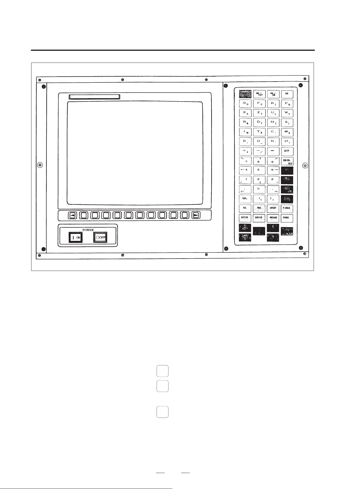
EXPLANATION FOR CRT/MDI PANEL
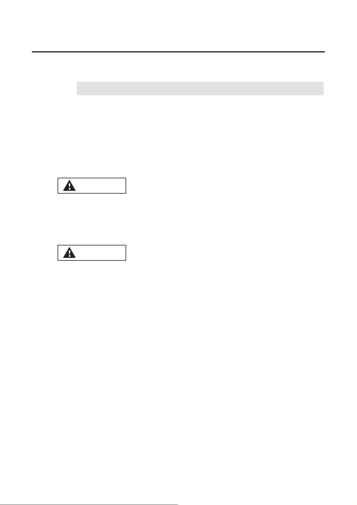
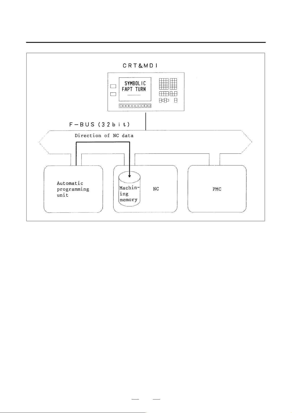
CR T/MDI panel is composed of a 14–inch CRT or 10.4–inch LCD color
graphic display and keys which consist of alphabet, numerics, and the
others. It is as shown below.
1. EXPLANA TION FOR
CRT/MDI PANEL
MDI panel for 15–TFB/15–TTFB
9
Page 22
1. EXPLANATION FOR
CRT/MDI PANEL
EXPLANATION FOR CRT/MDI PANEL
B–61804E–2/05
MDI panel for 16–T/16–TT CAP II
10
Page 23
B–61804E–2/05
EXPLANATION FOR CRT/MDI PANEL
Text type Symbol type
1. EXPLANA TION FOR
CRT/MDI PANEL
MDI panel for 16–TC/16i–TA CAP II (10.4–inch horizontal type LCD/MDI unit)
11
Page 24
1. EXPLANATION FOR
CRT/MDI PANEL
EXPLANATION FOR CRT/MDI PANEL
Text type
Symbol type
B–61804E–2/05
MDI panel for 16–TC/16i–TA CAP II (10.4–inch vertical type LCD/MDI unit)
12
Page 25
B–61804E–2/05
EXPLANATION FOR CRT/MDI PANEL
Text type Symbol type
1. EXPLANA TION FOR
CRT/MDI PANEL
MDI panel for 16–TC/16i–TA CAP II (14–inch horizontal type CRT/MDI unit)
13
Page 26
1. EXPLANATION FOR
CRT/MDI PANEL
EXPLANATION FOR CRT/MDI PANEL
B–61804E–2/05
MDI panel for 16i–TA CAP II (separate type MDI unit: text type)
MDI panel for 16i–TA CAP II (separate type MDI unit: symbol type)
14
Page 27
B–61804E–2/05
EXPLANATION FOR CRT/MDI PANEL
1. EXPLANA TION FOR
CRT/MDI PANEL
Fig. 1 14–inch color CRT/MDI panel external view
The mode in which the CR T/MDI unit is used for the creation of CNC data
with the Symbolic FAPT is called FAPT mode. The mode in which the
CRT/MDI is used for operations related to the CNC functions, such as
editing of created data, setting and check of various parameters for CNC
machining and tool offset amounts, and check of travel during CNC
machining, is called CNC mode.
T o change the mode of the CRT/MDI unit between F APT and CNC/PMC,
press the mode selector keys with lamps as shown below.
D For 15–TFB
MMC/
When
When
is pressed, FAPT screen is displayed.
FAPT
PMC/
is pressed, CNC screen is displayed.
CNC
D For 16–T CAP II
FAPT
When
is pressed, the FAPT screen is displayed.
To display the CNC screen, press one of the other function keys.
15
Page 28

2. KEYS EFFECTIVE IN
FAPT MODE
KEYS EFFECTIVE IN FAPT MODE
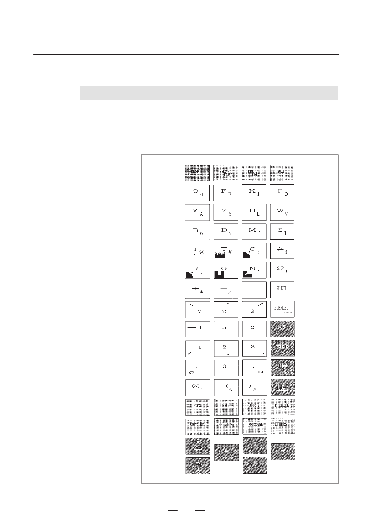
2
EXPLANATION FOR CRT/MDI PANEL
The diagram at under shows only the keys used in the Symbolic FAPT.
The symbols omitted are not used in FAPT mode.
B–61804E–2/05
16
Page 29
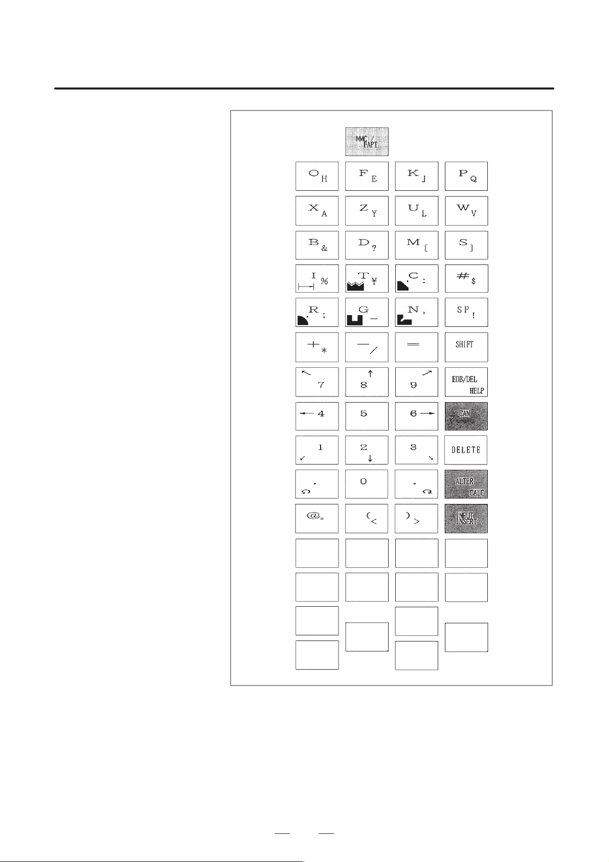
B–61804E–2/05
EXPLANATION FOR CRT/MDI PANEL
2. KEYS EFFECTIVE IN
FAPT MODE
17
Fig. 2 (a) 15TFB/TTFB
Page 30
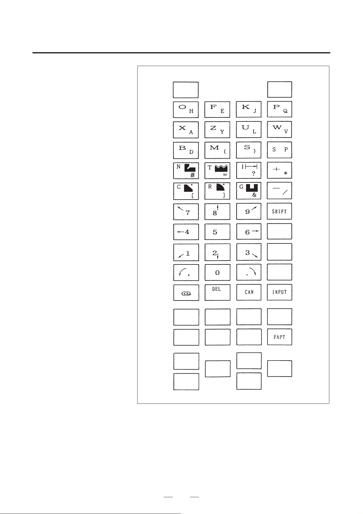
2. KEYS EFFECTIVE IN
FAPT MODE
EXPLANATION FOR CRT/MDI PANEL
B–61804E–2/05
18
Fig. 2 (b) 16T/TT CAP II
Page 31

B–61804E–2/05
EXPLANATION FOR CRT/MDI PANEL
Text type Symbol type
2. KEYS EFFECTIVE IN
FAPT MODE
MDI panel for 16–TC/16i–TA CAP II (10.4–inch horizontal type LCD/MDI unit)
19
Page 32

2. KEYS EFFECTIVE IN
FAPT MODE
EXPLANATION FOR CRT/MDI PANEL
Text type
Symbol type
B–61804E–2/05
MDI panel for 16–TC/16i–TA CAP II (10.4–inch vertical type LCD/MDI unit)
20
Page 33

B–61804E–2/05
EXPLANATION FOR CRT/MDI PANEL
Text type Symbol type
2. KEYS EFFECTIVE IN
FAPT MODE
MDI panel for 16–TC/16i–TA CAP II (14–inch horizontal type CRT/MDI unit)
21
Page 34

2. KEYS EFFECTIVE IN
FAPT MODE
EXPLANATION FOR CRT/MDI PANEL
B–61804E–2/05
MDI panel for 16i–TA CAP II (separate type MDI unit: text type)
MDI panel for 16i–TA CAP II (separate type MDI unit: symbol type)
22
Page 35

B–61804E–2/05
EXPLANATION FOR CRT/MDI PANEL
(1)Keys for parts figure input
Used for increment amount input. (See CHAPTER III,
3.2.3) Can also be used for inputting the alphabet I.
Used when commanding thread. Can also be used for
inputting the alphabet T.
Used when commanding chamfer. Can also be used for
inputting the alphabet C.
Used when commanding rounding. Can also be used
for inputting the alphabet R.
Used when commanding grooving. Can also be used
for inputting the alphabet G.
2. KEYS EFFECTIVE IN
FAPT MODE
Used when commanding neck. Can also be used for inputting the alphabet N.
Called ‘delete key’. This key is used to set undefined
data.
Called the cancel key . Only 1 character is
erased if this key is proceed after inputting
data and before pressing the INPUT key.
To cancel all the data input so far, press
, .
SHIFT
CAN
Arithmetical function keys (The – can also
be used as minus signs).
23
Page 36

2. KEYS EFFECTIVE IN
FAPT MODE
EXPLANATION FOR CRT/MDI PANEL
(2)Other keys
Used when inputting the alphabet at the right bottom of the key.
All the data in the key–in buffer line is cancelled
if is pressed after pressing this key.
CAN
Used to input space.
At–mark key. Pressed before writing the file
name, to display a @, when storing or calling family programs and material files in the sub memory .
Input key. This key is used to write the entered
data into memory.
B–61804E–2/05
24
Page 37

B–61804E–2/05
3
SOFT KEY
EXPLANATION FOR CRT/MDI PANEL
The 12 keys under the CR T are called soft keys. The function of the keys
change according to the screen displayed. The function for each screen
are framed at the bottom of the screen.
3. SOFT KEY
25
Page 38

III. PROGRAMMING AND
OPERATION BY SYMBOLIC FAPT
Page 39

B–61804E–2/05
1
OPERATION BY SYMBOLIC FAPT
SYMBOLIC FAPT
The Symbolic FAPT is an epoch making NC automatic programming
system which enables even unexperienced NC operators to prepare NC
tape immediately according to the instructions on the graphic display
CRT.
Each process from design drawings to NC tape preparation is entirely
advanced by the conversational operation with the graphic display CR T.
For (1) selection of coordinate system by drawing methods (2) selection
of figures of blank and input of dimensions (3) input of parts figures and
dimensions, and (4) selection of machining process and decision or
cutting conditions etc., the operator has only to answer questions from the
CR T.
The parts figure can be input simply by depressing corresponding symbol
keys on the operator’s panel according to the profiles of a workpiece
described on design drawings.
When dimensions and various data are input, various pieces of reference
information are illustrated on the CRT from time to time, and questions
are given to the operator using daily language.
When data are input, the figure of blank and parts profile are drawn
immediately , and automatic calculations of NC command data are started.
The tool path is concurrently displayed as figures.
Unless otherwise specified, this manual uses the screens of the 15–TFB
or 16–T CAP II to describe functions.
PROGRAMMING AND
1. SYMBOLIC FAPT
29
Page 40

2. START OF SYMBOLIC
FAPT PROGRAMMING
START OF SYMBOLIC FAPT PROGRAMMING
2
PROGRAMMING AND
OPERATION BY SYMBOLIC FAPT
CAUTION
After turning on the power, do not touch the keyboard until
the initial FAPT screen is displayed. Some keys are
specifically designed for maintenance or other special
operations; if any of these keys is pressed before the initial
screen is displayed, the machine may behave
unexpectedly.
B–61804E–2/05
The programming by Symbolic FAPT can be started by turning on the
power.
The initial screen is displayed 20 seconds after turning power on.
Symbolic FAPT
side initial screen
(16–T CAP II).
After the “SYSTEM EDITION,” the series/version number will be displayed.
Immediately after the series/version number, the language of the message
currently being displayed will be indicated in English.
V arious jobs are selectable by depressing soft keys, while the initial pattern appears on CRT screen.
[FAPT EXEC] Depress this key for NC programming, while. . . . .
monitoring the CRT screen.
[FAMILY PROGRAM] For calling a family program from. . .
30
submemory, floppy cassette or paper tape,
depress this key.
For using the memory cassette, the memory
cassette adapter is necessary.
For using the paper tape, FANUC PPR is
necessary.
Page 41

B–61804E–2/05
PROGRAMMING AND
OPERATION BY SYMBOLIC FAPT
[DATA SET] This key is used for input/output and setting of. . . . . .
system parameter, machine tool file (MTF),
setting data, material file and tooling data. For
storage of material files and tooling files,the
submemory, the memory cassette or paper tape is
used.
[AUXILIARY] This key is used to initialize sub memory. . . .
“FAPT execution”
2. START OF SYMBOLIC
FAPT PROGRAMMING
Press the “FAPT execution” on the initial screen to allow the FAPT
execution procedures menu to be displayed, By pressing the Software key
“Execution”, programming is initiated according to the procedures.
Correction can be easily made by directly selecting any menu on
correcting programs. For example, press the Software key “2” for
selecting input of final parts figure. Press the “5” for creating the NC data.
However, it is not possible to execute programming in the reverse order,
namely from larger memory number to smaller one.
Press the “End” when the above screen is being displayed to return to the
initial screen.
31
Page 42

3. EXECUTION OF
SYMBOLIC FAPT
EXECUTION OF SYMBOLIC FAPT
3
PROGRAMMING AND
OPERATION BY SYMBOLIC FAPT
It is possible to perform NC programming, monitoring the drawing in the
“F APT” screen. Proceed with programming, monitoring the CR T screen
according to the following procedures:
B–61804E–2/05
32
Page 43

B–61804E–2/05
3.1
BLANK AND DRAWING (DRAWING AND BLANK)
PROGRAMMING AND
OPERATION BY SYMBOLIC FAPT
WARNING
1 Select the same material as that of the workpiece to be
machined. If a desired material option is not displayed on
the material menu, cancel the machining of the workpiece.
Failure to select the correct material may result in the
machining being performed under incorrect cutting
conditions, or the tool colliding with the workpiece and/or
machine, possibly causing damage to the machine and/or
tool itself, or injury to the user.
2 Select the blank figure corresponding to that of workpiece
to be machined. Failure to select the correct figure may
result in the tool colliding with the workpiece and/or
machine, possibly causing damage to the machine and/or
tool itself, or injury to the user.
3 Enter the correct blank dimensional data for the workpiece
to be machined. Failure to enter the correct data may result
in the tool colliding with the workpiece and/or machine,
possibly causing damage to the machine and/or tool itself,
or injury to the user.
3. EXECUTION OF
SYMBOLIC FAPT
Soft key “1”
Go to the screen for the above processes. The meaning of each question
is as follows:
(a)MATERIAL NO MN =. . . . . . . . . . . . . . . . . . . . . . . .
This is a question for selecting the material of blank. Input the number
corresponding to the material NO. For example, key in 4 when
selecting aluminum.
33
Page 44

3. EXECUTION OF
SYMBOLIC FAPT
PROGRAMMING AND
OPERATION BY SYMBOLIC FAPT
B–61804E–2/05
(b)STANDARD SURFACE ROUGHNESS NR =. . . . .
, 2. , 3. , 4. )
(1.
This is a question used to select the surface roughness. Input the
number of
“2” if nearly all areas of machining drawing have
marks on the machining drawing. For example, key in
. It is possible
to skip this question using system parameter No.10.
(c)DRAWING FORMAT DF =. . . . . . . . . . . . . . . . . . .
This question is used to select the drawing format.
When the horizontal figure drawing is performed:
1. 2.
When the vertical figure drawing is performed:
In the case of horizontal drawing, select the drawing format 1 or 3 and
2 or 4 to easily input the dimension data on programming while the
dimension value of drawing is written based on the left and right sides,
respectively. This question can be skipped by setting of the system
parameter No.9.
34
Page 45

B–61804E–2/05
PROGRAMMING AND
OPERATION BY SYMBOLIC FAPT
3. EXECUTION OF
SYMBOLIC FAPT
(d)BLANK FIGURE BF =. . . . . . . . . . . . . . . . . . . . . . .
(1. Cylinder 2. Hollow cylinder 3. Special blank)
This question is used to select the blank figure. Input the number
corresponding to the blank figure. For example, key in 1 to select the
cylinder.
BLANK SIZE
DIAMETER D =. . . . . . . . . . . . . . . . . . . . . .
INNER DIAMETER D0 =. . . . . . . . . . . . . . .
LENGTH L =. . . . . . . . . . . . . . . . . . . . . . . .
The diameter (D) and length of blank (L) are indicated.
In the case of hollow cylinder, the inner diameter (D0) is also
displayed.
BASE LINE ZP=. . . . . . . . . . . . . . . . . . . . . . . . . . .
It is used to specify at which part of blank the coordinate system (X
axis) to be programmed exists.
SURPLUS THICKNESS TX =. . . . . . . . . . . . . . . . .
TZ =
If a special blank is selected as blank figure, the X and Y components
of surplus thickness are displayed.
When data is input to the TX and TZ, it is assumed that the blank has
a constant surplus thickness. When nothing is input to the TX and TZ,
it is possible to define a free blank figure. The definition method is
described in the following item of Blank and Part (Part Figure).
DEPTH OF CHUNKING ZC =. . . . . . . . . . . . . . . . .
Input the data to determine the drawing position of chuck when the
animation drawing function option is provided. See “Chapter 3
Section 3.6 Check of NC data (animation drawing function)” for
details.
Insert the “, ” mark between data on inputting data to allow plural
number of data to be input simultaneously.
Example)
Input as in the following to to allow several data to be input
simultaneously when BF=1, L=100, D=150, and ZP=5 are input:
BF=1, 100, 150, 5
“INPUT”
Meaning of software key
[ESCAPE] It is used to return to the menu screen.. .
[HELP] It is displayed when each question regarding the. . . . .
drawing format, blank figure, blank size, position of
base line is asked.
Press this key when the meaning of each question is
unknown.
Then the following screen appears:
35
Page 46

3. EXECUTION OF
SYMBOLIC FAPT
PROGRAMMING AND
OPERATION BY SYMBOLIC FAPT
When it is pressed in the case of drawing format question:
In the case of horizontal drawing:
B–61804E–2/05
In the case of vertical drawing:
When it is pressed in the case of question for blank format, blank size, or
position of base line:
In the case of horizontal drawing:
36
Page 47

B–61804E–2/05
PROGRAMMING AND
OPERATION BY SYMBOLIC FAPT
In the case of vertical drawing:
[MAT.NAME] Press this software key to see the name of 18th. .
material or thereafter while 18 or more blank
materials are registered.
[CURSOR ±] The cursor moves in forward direction.. . .
[CURSOR ´] The cursor moves in backward direction.. . .
3. EXECUTION OF
SYMBOLIC FAPT
[NEXT PAGE] The next screen appears. If the input data contradicts. .
or there PAGE are undefined data, the following
message is displayed and it is no t po s si bl e t o move to
the next page: “KEY IN AGAIN”
NOTE
Normally, the next screen is automatically displayed when
all questions are answered on one screen. Press the
“NEXT P AGE” if it is not required to answer all questions or
data has been input to all questions. Also, it is possible to
allow the screen to keep being displayed for several
seconds after answering all questions or to disable
advancing to the next screen.
When the standard surface roughness or drawing format is
fixed, it is possible to skip these questions. See “Chapter
7 section 1.1” for the method of skipping the questions.
Set the system parameter No.19 to determine either of
horizontal or vertical drawing.
37
Page 48

3. EXECUTION OF
SYMBOLIC FAPT
3.2
BLANK AND PART (PART FIGURE)
PROGRAMMING AND
OPERATION BY SYMBOLIC FAPT
WARNING
1 After entering part figure data, check the entered data.
Failure to enter correct data may result in the tool colliding
with the workpiece and/or machine, or forced machining
occurring, possibly causing damage to the workpiece,
machine, and/or tool itself, or injury to the user.
2 For a conversational program for which machining process
data has been prepared, if part figure data is modified, the
cutting area specified in the machining definition may be
changed. Operating the machine based on NC data in
memory , with an incorrect cutting area specified, may result
in the tool colliding with the workpiece and/or machine,
possibly causing damage to the machine and/or tool itself,
or injury to the user.
B–61804E–2/05
CAUTION
1 When entering threading data, check the data that is
automatically calculated by pressing the [OUTER
THREAD], [INNER THREAD], or [SQUARE THREAD] soft
key. If this data is incorrect, the workpiece cannot be
machined properly.
2 Check the figure data that is automatically inserted by the
batch input function for chamfering/corner R. If this data is
incorrect, the workpiece cannot be machined properly.
3 Check the figure data that is automatically created by the
pattern figure input function. If this data is incorrect, the
workpiece cannot be machined properly.
4 Check the data that is automatically set by the neck corner
input function. If this data is incorrect, the workpiece cannot
be machined properly.
38
Page 49

B–61804E–2/05
PROGRAMMING AND
OPERATION BY SYMBOLIC FAPT
3. EXECUTION OF
SYMBOLIC FAPT
3.2.1
Drawing of Program Coordinate System and Blank Figure
The coordinate axis and blank figure matching the drawing format
previously selected are drawn on the screen.
D The blank is plotted by a dotted line.
D The left end of the blank is plotted by a solid line to indicate the chuck
side.
D The blank is automatically scaled so that it is accommodated with the
screen, irrespective of its dimensions.
The system requests you to input the part figure by the following display
in conversational area on the CRT screen.
3.2.2
Part Figure Input (Input Method of with Figure)
ELEMENT SYMBOL ES =. . . . . . . . . . . . . . . . . . . . . .
D If the blank is long laterally , the conversational area is provided on the
lower side of the CRT screen, and if it is long longitudionally, the
conversational area is provided on the right side of the CRT screen.
This decision is automatically done according to the dimensions of
input blanks.
The part figure can be input by depressing the figure symbol keys
sequentially along the profile of a part. T en keys for numerical input and
alphabetic keys indicating the chamfering, rounding, threading,
grooving, and necking are employed as figure symbol keys.
39
Page 50

3. EXECUTION OF
SYMBOLIC FAPT
PROGRAMMING AND
OPERATION BY SYMBOLIC FAPT
B–61804E–2/05
(Example)
Start / End
point point
For a figure illustrated above, input the following keys along the drawing.
C
C
²
³
G
´
G
±
³
T C
R
¿
²
G
G
³
±
T C
²
C
±
The system will ask you necessary dimension, each time these figure
symbol keys are depressed.
(1)Contents of the question and the meaning of symbolic key.
Surface roughness
The system asks you the “surface roughness”, each time the figure
element symbol like a circle, a straight line, etc. is inputted. The
already designated “standard surface roughness” is automatically
displayed on the CRT screen at this time. If this value is allowable,
depress INPUT key only.
If you desire to change the surface roughness at that place only , select
the number of
symbols 1, 2, 3, or 4.
NOTE
By parameter setting on parameter No.0010, the question
on the surface roughness can be skipped. When this
question is skipped, the standard surface roughness is
employed.
Start point
The system asks you the start point at the first step of figure input only .
SDX Diameter value at start point. . . . .
SZ Z value at start point. . . . . . .
PE Whether a part exists on the left side or on right side along. . . . . . .
a series of a figure profile to be inputted, is selected by
1 or 0.
The questions are made for the first figure element only, when a part
figure is inputted.
40
Page 51

B–61804E–2/05
PROGRAMMING AND
OPERATION BY SYMBOLIC FAPT
3. EXECUTION OF
SYMBOLIC FAPT
Straight line
¾ ´ ½ ² ³ ¼ ± ¿
(a) ELEMENT SYMBOL ES =. . . . . . . . . . .
Input an arrow along the profile figure when the system asks you
the above question.
For example, input
¾
.
INPUT
(b)SURFACE ROUGHNESS SR =. . . . . . . .
Input the number of
marks indicating the surface roughness
when the system asks you the surface roughness.
(c) The system will ask you the following items sequentially, starting
with the top item by displaying these items on the CRT screen.
END POINT DX = Diameter value at end point. . . . . . . .
Z = Z value at end point
TANGENT LAST TL = Whether the profile touches. . . .
the last figure or not.
TANGENT NEXT TN = Whether the profile touches. . . .
the next figure or not.
ANGLE FROM Z A = Angle from Z axis. . . .
You have to input only the dimensions described on the drawing.
Depress
INPUT
key only , if a dimension is not found on the drawing.
The system does not always ask all the above items, depending
upon the input arrow directions, but it ask you necessary numerical
values only, and you have to input only those described on the
drawing.
(d)If data are insufficient, “KEY IN AGAIN” is displayed.
Circle
(a) ELEMENT SYMBOL ES =. . . . . . . . . . . . .
Input either
or key along the progressive direction of
the circle when the system asks you the above question.
(b)SURFACE ROUGHNESS SR =. . . . . . . . . .
Input the number of
marks indicating the surface roughness
when the system asks you the above question.
(c) END POINT DX = Diameter value at end point. . . . . . . .
Z = Z value at end point
TANGENT LAST TL = Whether the profile touches. . . .
the last arrow figure or not.
TANGENT NEXT TN = Whether the profile touches. . . .
the next arrow figure or not.
RADIUS R = Radius value of circle. . . . . . . . . . .
CENTER CDX = X value at circle center. . . . . . . . . . .
(diameter coordinate value)
CZ = Z value at circle center
41
Page 52

3. EXECUTION OF
SYMBOLIC FAPT
PROGRAMMING AND
OPERATION BY SYMBOLIC FAPT
B–61804E–2/05
The system asks you the above questions sequentially by
displaying these items on the CRT screen. Input only such
dimensions as are known from the drawing. Depress
INPUT
only, if a corresponding dimension is not found on the drawing.
(d)If data are insufficient or if an invalid numerical value was input,
KEY IN AGAIN is displayed.
(e) The system asks you the following question when a profile figure
transfers from a straight line to circular arc or from a circular arc
to a circular arc.
SELECT START POINT or END POINT
(³: RIGHT ²: LEFT ´: ABOVE ±: BELOW)
The parts figure input comprises two methods when a profile figure
transfers from a straight line or a circular arc.
½
When
keys were depressed;
key
The start point is either “left side”
or “lower side”.
The start point is either “right side”
or “upper side”.
When keys were depressed;
The start point is either “right
side” or “lower side”.
The start point is either “left
side” or “upper side”.
When the system asks you “SELECT ST ART POINT” to identify the
following two possible methods from each other, you have to select
the right side (³), left side (²), above (´) or below (±) by the
²
³
,
Chamfering
Chamfering is designated by
´
,
, or
±
key.
C
, which indicates the capital of
C
chamfer.
(a) ELEMENT SYMBOL ES =. . . . . . . . . . . . .
Answer
when the system asks you the above question.
C
42
Page 53

B–61804E–2/05
PROGRAMMING AND
OPERATION BY SYMBOLIC FAPT
(b)SURFACE ROUGHNESS SR =. . . . . . . . . .
Input the number of
marks indicating the surface roughness
when the system asks you the above question.
(c) CHAMFER C =. . . . . . . . . . . . . . . . . . . . . .
Input the chamfering amount for the above question.
(d)The chamfering amount is figured as shown below.
Straight line and straight line
Straight line and circular arc
Circular arc and circular arc
3. EXECUTION OF
SYMBOLIC FAPT
C
Straight line and straight line Straight line and circular arc Circular arc and circular arc
CC
(e) The chamfering is displayed on CRT screen as shown below.
½ ½³
C C C
Rounding
Rounding is designated by
R
, which indicates capital of rounding.
R
(a) ELEMENT SYMBOL ES =. . . . . . . . . . . . .
Input
when the system asks you the above question.
R
(b)SURFACE ROUGHNESS SR =. . . . . . . . . .
Input the number of marks indicating the surface roughness when
the system asks you the above question.
(c) RADIUS R =. . . . . . . . . . . . . . . . . . . . . . . .
Input the radius value for rounding when the system asks you the
above question.
43
Page 54

3. EXECUTION OF
SYMBOLIC FAPT
Straight line and straight line Straight line and circular arc Circular arc and circular arc
PROGRAMMING AND
OPERATION BY SYMBOLIC FAPT
(d)Rounding is done as follows.
(e) Rounding is displayed as a figure on the CRT screen as shown
below.
½ ½¼
R R R
B–61804E–2/05
CAUTION
Keys
, and should be selectively used for
R
specifying a circular arc as described below.
D (1) A tangential circule being caught by 2 straight lines, (2) a
tangential circule being caught by a straight line and a circular
arc, and (3) a tangential circle being caught by circular arcs can
be specified by
key as a figure element key, if their
R
radiuses are known, as illustrated above.
D If the coordinate values of a circular arc center, a start point and
an end point are written on a drawing, the rounding can be
specified by using
or key.
44
Page 55

B–61804E–2/05
PROGRAMMING AND
OPERATION BY SYMBOLIC FAPT
3. EXECUTION OF
SYMBOLIC FAPT
Threading
Threading is designated by
T
, which indicates the capital of thread.
T
(a) ELEMENT SYMBOL ES =. . . . . . . . . . . . .
Input
when the system asks you the above question.
T
(b)ON WHICH ELEMENT? EE = On which element is . . . .
(0: LAST 1: NEXT) threading done?
LENGTH LT = Length of thread. . . . . . . . . . . . . . . . .
LEAD LD = Lead of thread. . . . . . . . . . . . . . . . . . .
MUL TIPLE NT = Number of threads of screw. . . . . . . . . . . . . . .
The system asks you these questions, starting with the top item by
displaying them on CRT screen.
(c) “ON NEXT ELEMENT” or “ON LAST ELEMENT”?
is input before and after arrows, in general.
T
It indicates whether threading is made on a figure element to be
input or on the last figure element already input.
“ON NEXT ELEMENT” Input “1”.. . . . . . .
“ON LAST ELEMENT” Input “0”.. . . . . . .
Identify “ON NEXT ELEMENT” and “ON LAST ELEMENT”
from each other in the following illustration.
In case of the next element In case of the next element
´ ´
¾ ¾
In case of the last element In case of the last element
´ ´
¾ ¾
² ²
T T
² ²
T T
45
Page 56

3. EXECUTION OF
SYMBOLIC FAPT
PROGRAMMING AND
OPERATION BY SYMBOLIC FAPT
B–61804E–2/05
Reversing screws can be machined by selectively specifying either
“on the next element” or “on the last element”. If the rotating direction
of the blank is the same and the cutting direction is reversed in the
previous figure, screws are threaded reversely.
CAUTION
When chamfering was made by , the length of thread
C
can be calculated from the intersection of linear element
before chamfering.
(d)Lead length, pitch, and number of thread
The lead is defined as the Z–axis direction length when a screw
returns to the original angle after turning once.
In case of a one–thread screw, the pitch coincides with the lead.
In case of a three–thread screw , 1/3 of lead corresponds to the pitch.
The lead of a taper screw is also calculated in the Z–axis direction.
(e) Depth of thread
T ogether with the prompt on the depth of thread DT, the following
soft keys are displayed on the screen:
DT=_
ESCAPE BACK OUTER INNER SQUARE CURSOR CURSOR NEXT
PAGE THREAD THREAD THREAD PAGE
If one of the soft keys is pressed, the depth of thread DT is
automatically calculated. The calculation is defined as follows:
Pitch = LD (lead)/NT (number of threads)
OUTER THREAD: Pitch Constant (system parameter
No.174), initial value 0.7578
INNER THREAD: Pitch Constant (system parameter
No.125), initial value 0.6495
SQUARE THREAD: Pitch/(2 NT (number of threads))
If the value obtained by automatic calculation is unsatisfactory,
modify the data manually . For a trapezoidal thread, enter the data
manually. After the depth of thread (DT) has been automatically
calculated and specified, the cursor is repositioned to the first
prompt.
46
Page 57

B–61804E–2/05
PROGRAMMING AND
OPERATION BY SYMBOLIC FAPT
3. EXECUTION OF
SYMBOLIC FAPT
Grooving
Grooving is designated by
G
, which indicates the capital of groove.
G
(a) ELEMENT SYMBOL ES =. . . . . .
Input
when the system asks you the above question.
G
(b)SURFACE ROUGHNESS SR =. . .
Input the number of
marks indicating the surface roughness
when the system asks you the above question.
(c) ON WHICH ELEMENT? EE = On which element is . . . .
grooving made?
DIRECTION DN = Grooving direction. . . . . . . . . . . . . .
WIDTH WT = Grooving width. . . . . . . . . . . . . . . . . .
DEPTH DT = Grooving depth. . . . . . . . . . . . . . . . . .
R/C OF CORNER (ALONG ELEMENT)
1’ST KC = CV = . . . . . . . .
2’ND KC = CV = . . . . . . .
3’RD KC = CV = . . . . . . .
Designation of groove
shape
4’TH KC = CV =. . . . . . .
The system asks you these questions sequentially , starting with the
top question by displaying them on the CRT screen.
Input a numerical value for each question.
² ²
G
(d)“ON NEXT ELEMENT” or “ON LAST ELEMENT”?
is input before and after arrows, in general.
G
It indicates whether threading is made on a figure element to be
input or on the last figure element already input.
“ON NEXT ELEMENT” Input “1”.. . . . . . .
“ON LAST ELEMENT” Input “0”.. . . . . . .
Identify “ON NEXT ELEMENT” and “ON LAST ELEMENT”
from each other in the following illustration.
¿ ³
G
³ ½
G
47
Page 58

3. EXECUTION OF
SYMBOLIC FAPT
PROGRAMMING AND
OPERATION BY SYMBOLIC FAPT
B–61804E–2/05
(e) DIRECTION DN =. . . . . .
(³: RIGHT ²: LEFT ´: ABOVE ±: BELOW)
Designate the grooving direction by the arrow such as right (³),
left (²), above (´) or below (±) when the system asks you the above
question.
±±²
(f) After inputting the width and depth, the system asks you the figure
at groove corners. Numbers 1 to 4 area allocated to the corners of
each groove in the sequence of figure input.
(Example)
² ²
G
³ ³
G
Designate whether the figures of respective corners 1 to 4 are “round
(R)”, “chamfered (C)” or “left unmachined” according to the
following questions being displayed on the CRT screen.
R/C OF CORNER (ALONG ELEMENT)
1’ST KC = CV = Figure at the 1’st corner. . . . .
2’ND KC = CV = Figure at the 2’nd corner. . . . .
3’RD KC = CV = Figure at the 3’rd corner. . . . .
4’TH KC = CV = Figure at the 4’th corner. . . . .
D For rounding, depress
for “KC =” question, and input a radius
R
value for “CV =” question.
D For chamfering, depress
for “KC =” question, and input a
C
chamfering amount for “CV =” question.
D If a corner is neither rounded or chamfered, and it is left undone as
it is, depress
INPUT
key only, or depress [NEXT PAGE] key to
proceed to the next CRT screen when the system asks you the
question.
Trapezoid grooving (Automatic process determination function B is
required.)
As with grooving, to select trapezoid grooving, specify G.
(a) ON WHICH ELEMENT EE = Element on which a trapezoid. .
groove is made
(0: Last element, 1: Next element)
48
Page 59

B–61804E–2/05
PROGRAMMING AND
OPERATION BY SYMBOLIC FAPT
(b)DIRECTION DN = Direction of grooving. . . . . . . . . . .
(c) WIDTH WT =Distance between the . . . . . . . . . . . . . . .
(d)DEPTH DT = Depth of the groove. . . . . . . . . . . . . . .
3. EXECUTION OF
SYMBOLIC FAPT
Press the corresponding element
symbol key (´ ± ³ ²).
shoulders of the groove
CAUTION
If the line along which the width or depth of the groove is
measured is parallel to the X–axis (´ or ±), specify the width
or depth with a radius.
(e) R/C OF CORNER
1–ST KC = CV =. . . .
2–ND KC = CV =. . . .
3–RD KC = CV =. . . .
4–TH KC = CV =. . . .
Specify the figures of the groove corners in the order in which they
are defined.
49
Page 60

3. EXECUTION OF
SYMBOLIC FAPT
PROGRAMMING AND
OPERATION BY SYMBOLIC FAPT
B–61804E–2/05
When the above data is specified, a square groove is defined.
To define a trapezoid groove, specify the following data. To define a
conventional square groove, ignore the prompt and press the NEXT
PAGE soft key.
(f) WIDTH OF B. (1) W1 = Bottom width 1 of the groove. . . .
(This need not be specified if
bottom angle 1 of the groove is
specified.)
(g)WIDTH OF B. (2) W2 = Bottom width 2 of the groove. . . .
(This need not be specified if
bottom angle 2 of the groove is
specified.)
(h)ANGLE OF B. (1) A1 = Bottom angle 1 of the groove. . . .
(This need not be specified if
bottom width 1 of the groove is
specified.)
(i) ANGLE OF B. (2) A2 = Bottom angle 2 of the groove. . . .
(This need not be specified if
bottom width 2 of the groove is
specified.)
In figure definition, the system does not check the validity of the
specified bottom width (W*) and bottom angle (A*) of the groove.
The operator must carefully observe the figure drawn after the figure
is defined.
The positions of bottom widths 1 and 2 and angles 1 and 2 of the
groove depend on the direction of figure definition in the same way as
they do for R/C OF CORNER.
50
Page 61

B–61804E–2/05
PROGRAMMING AND
OPERATION BY SYMBOLIC FAPT
² ²
³ ³
3. EXECUTION OF
SYMBOLIC FAPT
G
G
[Reference]
1) Trapezoid grooving can be defined in the same way as conventional
grooving. (Automatic process determination is also allowed.)
2) If bottom width 1 (W1), bottom width 2 (W2), bottom angle 1 (A1),
and bottom angle 2 (A2) of a groove are specified, the width data has
priority over the angle data. The system ignores the angle data.
3) T o specify a trapezoid groove as shown in Fig. 3.2.2, do not define the
bottom width and bottom angle on the side of the groove having a
perpendicular wall.
Fig. 3.2.2 Defining a special trapezoid groove
Enter the bottom width or angle.
Leave the bottom width and bottom angle of the
perpendicular wall undefined.
51
Page 62

3. EXECUTION OF
SYMBOLIC FAPT
PROGRAMMING AND
OPERATION BY SYMBOLIC FAPT
B–61804E–2/05
4) It is recommended to specify the bottom widths when defining the
shape of a trapezoid groove. The trapezoid groove can be defined with
bottom angles, however, this definition may cause a small calculation
error.
5) The figure element copy function is convenient for defining two or
more identical trapezoid grooves.
Necking
Necking is designated by
N
, which indicates the capital of necking.
N
(a) ELEMENT SYMBOL ES =. . . . . . . .
Answer N when the system asks you the above question.
(b)SURFACE ROUGHNESS SR =. . . . .
Input the number of
marks indicating the surface roughness
when the system asks you the above question.
(c) WIDTH WT = Necking width. . . . . . .
DEPTH DT = Necking depth. . . . . . .
Input the necking width and depth for the above questions. The
necking direction is always 45° with reference to Z–axis.
The necking width and depth are as illustrated below.
(2)End of figure input
Key in the software key “END” or “INPUT” only for the following
question after ending the input of all machined figures:
ELEMENT SYMBOL ES =. . . . . . . .
52
Page 63

B–61804E–2/05
PROGRAMMING AND
OPERATION BY SYMBOLIC FAPT
3. EXECUTION OF
SYMBOLIC FAPT
Machine figure input before is drawn again on the CR T screen and the
message “SELECT SOFT KEY” is displayed at the lower side of
screen.
Check to see if there is any mistake in the input of figure by comparing
the drawing figure with that drawn on the screen. Press a software key
depending on the status at that time.
Meaning of software keys
[ESCAPE] It is used to return to the menu screen.. . . . . . . . . .
[BACK PAGE] It is used to return to the previous screen. . . . . . .
(drawing and blank screen).
[CORR.&ERASE] It is used to delete the machined figure. . . .
drawn on the screen and ERASE to modify
the machined figure. The modification
method is described below.
[CORRECTION] It is used to modify the machined figure. . . . .
based on the machined figure drawn on the
screen. The modification method is the
same as “CORR. & ERASE”.
[NEW] It is used to delete the machined figure on. . . . . . . . . . . . .
the screen and to input the figure again. All
elements input previously are deleted.
[LIST MODE] It is used to display all data previously. . . . . . .
input. Modification can be performed
similarly as in “CORRECTION”.
[DRAWNG RANGE] It is used to perform enlargement and. .
reduction of drawing. See “Chapter 3 1–3”
for the details.
[CHAMFER] It is used to insert the chamfer figure into all. . . . . . . .
of angles of machined figure drawn on the
screen. The details are described in the
following.
[C–AXIS MENU] It is displayed when the C axis FAPT. . . . .
function option is available.
[Y–AXIS MENU] Displayed when the Y–axis FAPT function. . . .
is provided.
[NEXT PAGE] It is used to move to the next page if there. . . . . . .
is no part modified.
[CORNERR] It is used to insert the corner R figure into. . . . . . . .
all of corners of machined figure drawn on
the screen.
53
Page 64

3. EXECUTION OF
SYMBOLIC FAPT
PROGRAMMING AND
OPERATION BY SYMBOLIC FAPT
B–61804E–2/05
When bit 1 of system parameter 19 is set to 1, the figure is displayed
vertically.
(3)Changing the color of a part figure or blank figure when it is modified
When a part figure or blank figure is modified (or created), the
elements before and after the element on which the cursor is placed are
displayed in different colors. As a result, the operator can easily tell
which element is currently being modified on the drawing.
System parameter 552 specifies the color of elements already
determined and system parameter 586 specifies the color of elements
to be determined.
Parameter No. Value Color Description
552 1 Red Specifies color of elements already
determined
586 3 Yellow Specifies color of elements to be
determined
Color Red Green Yellow Blue Purple
Value 1 2 3 4 5 6 7
Light
blue
White
NOTE
1 If the GRAPH MODE soft key is pressed after modification
of an original figure has been started by pressing the
CORRECTION soft key, the original figure cannot be
re–drawn.
2 If the ELEMENT BACK soft key is pressed in a definition
mode in which the end point of the previous element is
determined by the current element, the element before
these two elements is also drawn in the color of the
elements to be determined.
54
Page 65

B–61804E–2/05
PROGRAMMING AND
OPERATION BY SYMBOLIC FAPT
3. EXECUTION OF
SYMBOLIC FAPT
3.2.3
Input and Modification of Part Figure Data
Symbol
+
*
*
/
T
S
Arithmetic
contents
Addition
Subtraction
Multiplication
Division
tangent
sine
Arithmetic operation and function calculation
(1)
The arithmetic operation (addition, subtraction, multiplication,
division) and optional function calculations can also be executed when
inputting dimensions.
Examples Remarks
15 27.75 + 4.8
+
178.5 25.25
57.5 81.3
128 3.5
**
**
/
23
T
T ( )
15
S
S
23
15
( )
57.5 * 81.3 * indicates x.
/ indicates B.
The unit of angle is degree.
Arbitrary arithmetic operations are employable
inside parentheses.
The unit of angle is degree.
Arbitrary arithmetic operations are employable
inside parentheses.
C
A S
A
A T
R
P
C
cosine
arc sine
arc cosine
arc tangent
square root
square root
35
C
C
A S
A S
A C
A S
A T
177
R
R
P
35
( )
0.25
(
0.37
(
(
177
(
1.5, 4
(
0.25
0.37
3, 5
)
)
The unit of angle is degree.
Arbitrary arithmetic operations are employable
inside parentheses.
The unit of angle is degree.
Arbitrary arithmetic operations are employable
inside parentheses.
)
The unit of angle is degree.
Arbitrary arithmetic operations are employable
inside parentheses.
)
Parentheses are required without fail. A T
)
(numerator and denominator).
Optional arithmetic expressions are employable
inside parentheses, if any .
These examples mean 1.54 and 325, respectively .
P
3, 25
(
)
55
Page 66

3. EXECUTION OF
SYMBOLIC FAPT
PROGRAMMING AND
OPERATION BY SYMBOLIC FAPT
B–61804E–2/05
D Parentheses
and
(
are employable quadruply or less.
)
D Arithmetic symbols are employable whenever a dimension is
asked.
They are employable by an optional number, until one line is fully
filed.
D An arithmetic expression may be used conveniently when a cutting
condition is changed, for example. For setting the feedrate to 75%,
multiply the displayed numerical value by 0.75.
D It is recommended for using Symbolic FAPT to avoid mental
calculation as much as possible, but use this arithmetic function.
(2)
Input of incremental value
If the system asks you a dimension and you want to input an
incremental value from the present position, press
incremental value as shown below.
indicates the capital of
I
key after an
I
incremental.
(Example) 50.45 “I” “INPUT”
With
specification, the data in X–axis direction is radius value.
I
Change of figure element symbols
(3)
Depress soft key when the system asks you the following question.
ELEMENT SYMBOL ES =. . . . . . . . .
ELEMENT FORWRD
ELEMENT BACK
ELEMENT DELETE
Element advances. . . . . . . . . . . .
Element retreats. . . . . . . . . . . .
Element on the cursor is deleted.. . . . . . . . . . . .
The question place can be confirmed by a flickering figure element
symbol at the upper part of the CRT screen.
(Insertion example)
When depressing
R
with
½
³
Flickering
When depressing
C
with
½
. . . .
G
½
³ ±
R
³
Flickering
. . . .
½
G
³
C
±
56
Page 67

B–61804E–2/05
PROGRAMMING AND
OPERATION BY SYMBOLIC FAPT
3. EXECUTION OF
SYMBOLIC FAPT
(Deletion example) Depress
When depressing
DEL
with
½
DEL
key
³ ½ ³
. . .
Flickering
When depressing
DEL
with
½
G
³ ±
. . .
G
³ ±
Flickering
(Exchange)
For exchanging figure symbols, (1) delete old one after inserting new one,
or (2) insert new one after deleting old one.
(4)
Change of numerical value
The system will ask you necessary numerical values after figure
element symbols have been input. If a numerical value was input by
mistake, a correct numerical value can be input again after moving the
question place by depressing [CURSOR ±] or [CURSOR ´] CURSOR
key .
Select an optional question, and input a correct numerical value again.
[CURSOR ±] Element advances. . .
[CURSOR ´] Element retreats. . .
3.2.4
Blank Figure Input of Special Figure Blank
NOTE
If a figure element of data was corrected, press the software
key “END”.
(1)Input of blank figure
If a special figure is selected as the blank figure (BF = 3) and surplus
thicknesses (TX, TZ) are not defined as shown below , the blank figure
input screen is displayed after the data of the machining profile is
entered.
57
Page 68

3. EXECUTION OF
SYMBOLIC FAPT
PROGRAMMING AND
OPERATION BY SYMBOLIC FAPT
B–61804E–2/05
On the blank figure input screen, the machining profile is initially
drawn as the blank figure.
Select the software key “CORRECTION” or “LIST MODE” and
“NEW” to prepare the blank figure referring to the machined figure
and to prepare it newly, respectively.
Similar to input of parts figure data, use a symbolic key for entry of
blank figure. In this case, however, “G”, “T” and “N” keys cannot be
used for parts figure difinition.
Input a blank figure according to any one of the following three
formats.
(a) Start or end point is on the coordinate axis.
(Example 1) (Example 2)
(Example 3)
58
Page 69

B–61804E–2/05
PROGRAMMING AND
OPERATION BY SYMBOLIC FAPT
3. EXECUTION OF
SYMBOLIC FAPT
(b)Z axis coordinate values of start and end point are same.
(Example)
(c) Start and end point are same.
(Example)
(2)End of blank figure input
When all of blank figure has been input, key in the software key
“END” or “INPUT” if there is a question as shown below:
ELEMENT SYMBOL ES =. . . . . . . .
The element figure created so far is redrawn and the following message
is displayed: “Select software key”
Press the “NEXT PAGE” if there are no areas modified and when
proceeding to the next process.
59
Page 70

3. EXECUTION OF
SYMBOLIC FAPT
PROGRAMMING AND
OPERATION BY SYMBOLIC FAPT
B–61804E–2/05
3.2.5
Part Figure Input (Directory Input System)
The parts figure input system includes the system of entering the
definition data with displaying a defined figure, and the method of
entering the definition data while displaying in the table format. The
former is called “Graphic input system” (refer to para. 3.2.2 and 3.2.3 II)
and the latter is called “Directory input system”. The “Directory input
system” will be described here.
(1) In the screen of the graphic input system, press the soft key “LIST
MODE”.
[LIST MODE] The figure element input screen of the. . . .
directory input system is selected.
In this screen, select the element to be modified, using ELEMENT
FORWARD and ELEMENT BACK soft keys. (when the element is
inserted, it is inserted before the element is selected.)
Next, press “INPUT” when changing the figure data.
When it is desired to insert the element, key in the element symbol and
press “INPUT”. When only checking the data without modifying it,
check the objective element data, using ELEMENT FORWARD and
ELEMENT BACK soft keys.
(2)When the element is changed or inserted, the figure data input screen
is selected. The inquiry is displayed under the figure data list display .
60
Page 71

B–61804E–2/05
PROGRAMMING AND
OPERATION BY SYMBOLIC FAPT
3. EXECUTION OF
SYMBOLIC FAPT
In this screen, all data on the figure data are inquired. Adjust the cursor
to the data to be entered and input the data. Upon completion of
keying–in operation, press “NEXT PAGE” soft key.
(3)[NEXT PAGE] Again, the figure element input screen is. . . .
selected.
At this time, the modified data is registered on
the list screen.
[END] If END is pressed when the data input or modification is. . . .
completed, the display returns to the screen that the
figure data input is completed.
However, when an error is produced in the parts figure
data, it will not return to that screen 1 but will become
figure element input screen and the “Key in Again”
message is displayed.
In this case, modify the figure data of this element.
[GRAPH MODE] Press GRAPHIC MODE soft key to return to. .
the graphic input screen from the directory
input screen. At this time the position of the
element shown by the cursor will become the
same position with the elements where the
cursor was blinking in the directory input
system.
Drawing is also carried out up to its position
from the beginning.
3.2.6
Batch Input Functions for Chamfering and Corner R
(1)Chamfering
Normally, it is customary practice to chamfer a corner unless
otherwise specified for the machined parts in the drawing. Unlike the
specified chamfer, this chamfering is not described in the drawing, the
chamfering amount is constant and many in most cases.
Consequently, when the machined figure is prepared, it may be
troublesome to enter many chamfering elements. This function inputs
a given amount of chamfer exclusively to all corners to which no
chamfer (element symbol C) is input yet after all machined figures are
completely entered.
After the machined figure for turning is entered, the following screen
is displayed.
61
Page 72

3. EXECUTION OF
SYMBOLIC FAPT
PROGRAMMING AND
OPERATION BY SYMBOLIC FAPT
B–61804E–2/05
When the rightmost soft key [
] is pressed,
the following soft keys are displayed:
If the CHAMFER soft key is pressed, the yellow cursor blinks at a
corner of the machining profile whose chamfering data has not yet
been specified.
[CHAMFER]
At the same time, the question for the chamfering amount C and
surface roughness SR is displayed.
C = Input the chamfering amount.
SR = Input the number of
marks showing the surface
roughness.
When the control asks, input the chamfering amount and surface
roughness.
After keying in a required numeral, press [EXEC] soft key. Then,
chamfering is applied to the lighting corner, and the initial screen is
selected.
62
Page 73

B–61804E–2/05
PROGRAMMING AND
OPERATION BY SYMBOLIC FAPT
3. EXECUTION OF
SYMBOLIC FAPT
When no corner is present for the machined figure or chamfering is
applied to all corners or no section to designate chamfering is present,
the chamfering screen is not selected even when the soft key
“CHAMFER” is depressed. For the machined figure composed of
many elements, even when the soft key “CHAMFER” is depressed,
the chamfer may not be entered.
(2)Corner R
The batch input function for corner R is similar to the batch input
function for chamfering. The function specifies identical corner R
data for corners whose chamfering data is left unspecified after the
entire machining profile is specified.
The batch input function for corner R cannot be used for 5700 series
of 16–T CAP II.
After entering the turning figure, press the rightmost soft key [
Then, press the CORNER R key.
The yellow cursor lights at the corner whose chamfering data has not
yet been specified.
After entering the required data, press the EXEC soft key . The corner
R data is specified for the lighted corner. Then, the original screen is
displayed again.
].
63
Page 74

3. EXECUTION OF
SYMBOLIC FAPT
PROGRAMMING AND
OPERATION BY SYMBOLIC FAPT
B–61804E–2/05
NOTE
1 As a standard for a corner to be chamfered, set the
maximum angle to system parameter No.756. (Setting
range 0° t Angle x 180°) For example, if the angle is
set to 100, the cursor lights up as a chamfering corner with
100° or less angle. No cursor lights up for the portion more
than 100° angle.
Example) when setting system parameter No.756 as 100:
Related system parameter
010
NOTE
2 The initial value of Corner R amount can be set to system
parameter No.755. For example, if 0.2 is set to system
parameter No.755, when the control asks the chamfering
amount, the numeral 0.2 is entered as the initial value.
The inquiry for “SURFACE ROUGHNESS” can be omitted.
(System parameter No.0010) When omitted, “Standard
Surface Roughness” is adopted for surface roughness.
#7
#6 #5 #4 #3 #2 #1 #0
Bit 0 All surface roughness
Bit 1 Surface roughness for corner C
Bit 4 Surface roughness for corner R
0 : The inquiry is not omitted.
1 : The inquiry is omitted.
NOTE
3 No neck or groove portion is chamfered.
The corner for which thread cutting is designated is
chamfered.
64
Page 75

B–61804E–2/05
PROGRAMMING AND
OPERATION BY SYMBOLIC FAPT
3. EXECUTION OF
SYMBOLIC FAPT
Example) . .³G³. . . .³T±. .
3.2.7
Pattern Figure Input Function
“Pattern Figure” refers to a given shape or specified shape. This is a
convenient input method: a figure consisting of several elements can be
defined promptly by just answering the minimum question required for
its figure.
When the system asks “ELEMENTS SYMBOL – – – ES = ”, press
“PATTERN FIGURE”: the screen display changes to the soft key layout
showing the pattern figure input.
65
Page 76

3. EXECUTION OF
SYMBOLIC FAPT
PROGRAMMING AND
OPERATION BY SYMBOLIC FAPT
B–61804E–2/05
(1)Input of equal pitch/continuous groove
This input function is used for defining a figure in which a plurality
of grooves are arranged at an equal pitch. Press ”REPEAT
GROOVE”: the display as shown below will appear.
The meaning of each question is as follows.
(a) END POINT EDX =. . . . . . . .
EZ =
Input the end point of a straight line subsequent to a continuous
groove.
When defining the groove arranged in parallel to the Z–axis, it is
not necessary to input the end point value of X.
In contrast to the above, when defining a groove arranged in
parallel to the X–axis, it is not necessary to input the Z end point
value.
(b)QUANTITY N =. . . . . . . .
Input the number of grooves.
(c) PITCH PT =. . . . . . . . . . . . .
Input the space from the groove entrance to the next groove
entrance.
The following question is the same as in element G.
(d)DIRECTION DN =. . . . . . . .
WIDTH WT =. . . . . . . . . . . .
DEPTH DT =. . . . . . . . . . . .
Input the groove direction, width and depth.
(e) R/C OF CORNER
K1 = V1 =
K2 = V2 =
K3 = V3 =
K4 = V4 =
Designate each corner figure.
66
Page 77

B–61804E–2/05
PROGRAMMING AND
OPERATION BY SYMBOLIC FAPT
3. EXECUTION OF
SYMBOLIC FAPT
(f) SURFACE ROUGHNESS SR =. . . . .
Input the number of
marks indicating the surface roughness.
This surface roughness is applied to all elements forming this
figure. Further, it is also possible to skip this question by system
parameter No.0010 bit 2 (surface roughness to G). When skipped,
“Standard Surface Roughness” is adopted for the surface
roughness.
Meaning of a software key
[ESCAPE] The menu screen returns.. . . . .
[BACK P AGE] The screen, called by the sign ES = , returns. When. .
this software key is pressed, the input data will
become invalid.
[CURSOR ´] [CURSOR ±] The cursor goes up and down.. .
[EXEC] A shape is formed in accordance with the set data.. . . . . . . .
Example)
Method of defining a figure as shown above.
a) For normal figure input:
1) Definition from the origin direction ´²G²G²G²´². . .
2) Definition from the chuck direction ³±³G³G³G³±. . .
Each element is defined.
b) When the pattern figure input function is used:
1) Definition from the origin direction ´². . .
2) efinition from the chuck direction ³±³. . . . .
After defining the above so far, press “REPEAT & GROOVE”.
The setting of 1) above is as follows.
End point value of previous element DX = 40, Z = 8
END POINT EDX =. . . . . .
EZ = 36.0
QUANTITY N = 3. . . . . . .
PITCH PT = 10.0. . . . . . . . . . .
DIRECTION DN = ±. . . . . .
R/C OF CORNER
K1 = C V1 = 0.5
K2 = V2 =
K3 = V3 =
K4 = C V4 = 0.5
WIDTH WT = 4.0. . . . . . . . . .
DEPTH DT = 5.0. . . . . . . . . . .
67
Page 78

3. EXECUTION OF
SYMBOLIC FAPT
PROGRAMMING AND
OPERATION BY SYMBOLIC FAPT
Press “EXEC”
Thus, based on the preset data, a figure is defined and drawn.
The setting of 2) above is as follows.
End point value of previous element DX = 40, Z = 32
B–61804E–2/05
END POINT EDX =. . . . . .
QUANTITY N = 3. . . . . . .
PITCH PT = 10.0. . . . . . . . . . .
DIRECTION DN = . . . . . .
WIDTH WT = 4.0. . . . . . . . . .
DEPTH DT = 5.0. . . . . . . . . . .
Press “EXEC”
EZ = 0.0
R/C OF CORNER
K1 = C V1 = 0.5
K2 = V2 =
K3 = V3 =
K4 = C V4 = 0.5
Thus, based on the preset data, a figure is defined and drawn.
68
Page 79

B–61804E–2/05
PROGRAMMING AND
OPERATION BY SYMBOLIC FAPT
3. EXECUTION OF
SYMBOLIC FAPT
i) The figure defined by “REPEAT GROOVE” is defined as an
element by the arrow and G element row.
ii) Correct for each element. This is the same for the deletion.
iii)The relation between the pitch and groove is as shown below.
When DN = ± When DN = ²
NOTE
For pattern figure input, the end point value of the previous
element should already be fixed.
(2)Neck corner input
It is possible to define 3 types of DIN Standard neck corners. If
“NECK CORNER” is pressed, the display changes on the next screen.
³ “NECK CORNER”
In response to the question “TYPE =”, enter the neck figure type
number (1–3) for the type to be set.
The meaning of soft keys
“ESCAPE” Returns to the menu screen.. . . . . . . . .
“BACK PAGE” Returns to the “ES =” question screen.. . . . . .
69
Page 80

3. EXECUTION OF
SYMBOLIC FAPT
PROGRAMMING AND
OPERATION BY SYMBOLIC FAPT
1) Type 1: Neck grinding
B–61804E–2/05
The meaning of each question is as follows.
a) DEFINE DERECTION DD = (0: PV PH, 1: PH PV). . .
Specifies the direction that defines the element. If the current point
is PV and the PH direction is to be defined (vertical plane
horizontal plane), input 0. Conversely, if the current point is PH
and the PV direction is to be defined (horizontal plane vertical
plane) input 1.
b) END POINT P* EDX =. . . . . . . . .
EZ =
Inputting the end point value. If the define direction DD is 0, input
the PH point. If the define direction is 1, input the PV point.
c) WIDTH WT = (automatic setting) input neck width.. . . . . . . . . .
d) DEPTH DT = (automatic setting) input neck depth.. . . . . . . . . .
e) CORNER R R = (automatic setting) input the corner. . . . . . .
radius value.
The standard values of width, depth and corner R are set
automatically according to the diameter of the neck (PH point DX
value). To change these to other values, place the cursor on the
question and input the number.
f) SURFACE ROUGHNESS SR =. . . . .
Inputting the number of the
mark that displays surface
roughness. This surface roughness is appropriate to all the
elements that shape this figure. The standard setting value (value
of system parameter No.205) is set at the beginning automatically .
It is also possible to change to other values. By setting bit 1 of
system parameter No.10 to 1, it is possible to skip this question.
When it is skipped, the standard surface roughness setting value is
used.
70
Page 81

B–61804E–2/05
PROGRAMMING AND
OPERATION BY SYMBOLIC FAPT
The meaning of soft keys
“ESCAPE” Returns to the menu screen.. . . . . . . . . . . . . . . . .
“BACK PAGE” Returns to the neck type. . . . . . . . . . . . . .
“CURSOR ´” “CURSOR ±” Moves cursor up and down.. . . .
“EXEC” Creates the figure based on the. . . . . . . . . . . . . . . . . . . .
2) Type 2: Neck grinding (with side depth)
3. EXECUTION OF
SYMBOLIC FAPT
number selection screen.
data set.
The meaning of each question is as follows.
a) SIDE DEPTH W1 = inputs the depth of side depth.. . . . . . . . . .
The meaning of all other questions are the same as for Type 1.
3) Type 3: Neck threading
71
Page 82

3. EXECUTION OF
SYMBOLIC FAPT
PROGRAMMING AND
OPERATION BY SYMBOLIC FAPT
B–61804E–2/05
The meanings of the inquiries are:
(a) LENGTH LT = Thread length. . . . . . . . . . . . . .
(b)LEAD LD = Lead. . . . . . . . . . . . . . . .
(c) MULTIPLE NT = Number of threads. . . . . . . . . . . .
(d)THREADING DEPTH D1 = Threading depth. . .
For the meanings of the other inquiries, see the description of type 1.
When the threading depth (D1) is entered, the following soft keys are
displayed on the screen:
D1= METRIC
ESCAPE BACK OUTER INNER SQUARE CURSOR CURSOR EXEC
PAGE THREAD THREAD THREAD ° ±
If the OUTER THREAD, INNER THREAD, or SQUARE THREAD soft
key is pressed, the system automatically specifies the value of D1
(threading depth). The value is calculated using the following expression:
Pitch = LD (LEAD) B NT (MULTIPLE)
OUTER THREAD:
Pitch (P) Constant
(system parameter 174, initial value 0.7578)
INNER THREAD: Pitch (P) Constant
(system parameter 125, initial value 0.6495)
SQUARE THREAD: Pitch (P) B (2 NT (MULTIPLE))
System parameters 125 and 174 specify the constants to be used when the
elements of threading are manually defined.
If the automatically specified value is not suitable, change it manually.
To define a trapezoid thread, manually enter the data.
After the value of D1 is entered, the system automatically specifies the
values of WIDTH (WT), DEPTH (DT), and CORNER R (R). The values
are calculated as shown below:
WIDTH (WT): WT = 3.5 (constant) Pitch (P)
DEPTH (DT): DT = 1.2 (constant) Threading depth (D1)
CORNER R (R): R = 0.5 (constant) Pitch (P)
NOTE
1 The threading depth (D1) can be automatically determined
by pressing the OUTER THREAD, INNER THREAD, or
SQUARE THREAD soft key only when the values of LD
(LEAD) and NT (MULTIPLE) are specified.
2 If the value of LD (LEAD) or NT (MULTIPLE) is changed, the
D1 (threading depth) and DT (depth) must be calculated
again. Press the OUTER THREAD, INNER THREAD, or
SQUARE THREAD soft key to have the system
automatically specify suitable values.
72
Page 83

B–61804E–2/05
PROGRAMMING AND
OPERATION BY SYMBOLIC FAPT
3. EXECUTION OF
SYMBOLIC FAPT
4) Neck diameter (PH point DX value) and width, side depth, depth,
corner R (DIN Standards)
Diameter (X axis) Depth
Under 18 mm
Under 0.7087 inch
Above 18 mm below 80 mm
0.7087 to 3.15 inch
Above 80 mm
Above 3.15 inch
Example
(DT)
.25 mm
.0098 inch
.35 mm
.0138 inch
.45 mm
.0177 inch
Corner R
(R)
.6 mm
.0236 inch
.6 mm
.0236 inch
1.0 mm
.0394 inch
Width
(WT)
2.0 mm
.0787 inch
2.5 mm
.0984 inch
4.0 mm
.1575 inch
Side depth
(W1)
.1 mm
.0039 inch
.2 mm
.0079 inch
.3 mm
.0118 inch
Method of definition when defining the figure of this illustration.
a) Defining the figure by the existing method without using the
pattern figure input method
(1)Definition from zero point direction ´²¼R²R´². . .
(2)Definition from chuck direction ³±R³R½³±. . . . . . .
In this way, each element is defined one at a time.
b) Defining the figure using pattern figure input
(1)Definition from zero point direction ´ (End point PH). . .
(2)Definition from check direction ³ (End point PV). . . . . . .
Inputting elements in this way , after keying in the end point value (PH or
PV), press “neck corner”.
Input the following data with regard to each question for (1).
NECK TYPE P = 1. . . . . . . .
Questions and illustrations explaining neck type 1 are displayed here and
therefore the following data should be input.
Define direction DD =1 (0: PV³ PH, 1: PH ³ PV). . . . . . . .
End point PV EDX = 60.. . . . . . . . . .
EZ = 20.
Width WT = 2.5 (Automatic setting). . . . . . . . . . . . . . . .
Depth DT = 0.35 (Automatic setting). . . . . . . . . . . . . . . .
Corner R R = 0.6 (Automatic setting). . . . . . . . . . . . . .
Surface roughness SR = 2 (Automatic setting). . . . . . .
73
Page 84

3. EXECUTION OF
SYMBOLIC FAPT
PROGRAMMING AND
OPERATION BY SYMBOLIC FAPT
B–61804E–2/05
When “EXEC” is pressed the figure based on the data set is drawn.
Input the following data with regard to each question for 2.
NECK TYPE P = 1. . . . . . . . . .
Questions and illustrations explaining neck type 1 are displayed here and
therefore the following data should be input.
Define direction DD =0 (0: PV PH, 1: PH PV). . . . . . . .
End point PH EDX = 40.. . . . . . . . . .
EZ = 0.
Width WT = 2.5 (Automatic setting). . . . . . . . . . . . . . . .
Depth DT = 0.35 (Automatic setting). . . . . . . . . . . . . . . .
Corner R R = 0.6 (Automatic setting). . . . . . . . . . . . . .
Surface roughness SR = 2 (Automatic setting). . . . . . .
When “EXEC” is pressed the figure based on the data set is drawn.
i) The figure defined at neck corner input is separated and defined
into direction arrow elements and R.
ii) Carry out corrections and deletions one element at a time.
NOTE
1 Definition is possible if the element directly in front of corner
R is an element other than G/N/T, but the end point value
directly in front must be decided. Furthermore, it is not
possible to create it as the first element.
2 The neck is created in the corner of the vertical and
horizontal plane.
It is possible in the taper plane.
3 If define direction DD = 0 is input, the next end point symbol
is displayed as PH. Conversely, if define direction DD = 1
is input, the next end point symbol is displayed as PV.
Furthermore, the neck direction is decided automatically by
the define direction and end point value.
Examples Illustrations type 2 for horizontal figures
a) When define direction is 0 (PV: vertical plane PH: horizontal plane)
End point PH is upper left with regard to PV End point PH is upper right with regard to PV
End point PH is lower left with regard to PV End point PH is lower right with regard to PV
74
Page 85

B–61804E–2/05
End point PV is upper left with regard to PV End point PV is upper right with regard to PV
End point PV is lower left with regard to PH End point PV is lower right with regard to PH
PROGRAMMING AND
OPERATION BY SYMBOLIC FAPT
3. EXECUTION OF
SYMBOLIC FAPT
b) When define direction is 1 (PH: horizontal plane PV: vertical plane)
NOTE
4 As for the end point value, input the absolute values only.
It is not possible to input the incremental value.
5 Input positive neck, depth and side depth values.
6 Input values smaller than the difference between the Z
values of PV point and PH point for neck width. An alarm
(END POINT OR NECK WIDTH IS NOT CORRECT) is
displayed if a bigger value is input.
Note that if a bigger depth or side depth value is input, it is
possible that a figure other than a neck figure will be
created.
75
Page 86

3. EXECUTION OF
SYMBOLIC FAPT
PROGRAMMING AND
OPERATION BY SYMBOLIC FAPT
B–61804E–2/05
3) Figure element copy function
Having specified the start and end points of the figure to be copied,
once the number of copies has been keyed in, it is possible to define
the same figure repeatedly. This is useful when repeatedly inputting
special groove figures and complicated circular figures.
In the case illustrated above, when the soft key “PATTRN INPUT” is
pressed followed by “FIGURE COPY”, the following copy area
specification screen appears. Note however that when the “PATTRN
INPUT” key is pressed, the cursor must be next to the very last element,
as illustrated above.When the cursor has been moved by corrections to
element data etc., press the “FIGURE COPY” only after having made sure
to move the cursor next to the very last element. If the “FIGURE COPY”
key is pressed when the cursor is at an element other than the final one,
an error message will be displayed saying “CAN NOT USE THIS
FUNCTION” and the copy area specification screen will not appear.
76
Page 87

B–61804E–2/05
PROGRAMMING AND
OPERATION BY SYMBOLIC FAPT
3. EXECUTION OF
SYMBOLIC FAPT
a) The figure to be copied and the number of copies is specified in the
copy area specification screen.
Questions are as follows.
REPEAT NO. N = Specifies the number of repeat copies.. . . . . . . .
When the “NUMBER INPUT” is keyed in, the data is set for the
number of repeats.
When only “INPUT” is keyed in, the cursor point alternates between
the copy start and copy end point.
The meaning of soft keys
“ESCAPE”. Returns to the main menu screen.. . . . . . . . . . . .
“STOP” Returns to the ES = question screen. . . . . . . . . . . . . . . .
If this key is pressed, the copy area and
number of copies specified up until then
will be invalidated.
“CURSOR BACK”. The flashing cursor moves in the reverse. . . . .
direction.
“CURSOR FORW ARD” The flashing cursor moves in the regular.
direction.
“EXEC” Creates the figure based on the specified. . . . . . . . . . . . . .
copy area and the number of repeats.
b) To specify the copy start point, align the cursor to the copy start point
with the “CURSOR FORWRD”, “CURSOR BACK” key and press
the INPUT key.
When the copy start point has been specified, the message “SPECIFY
THE COPY END POINT” will appear.
c) To specify the copy end point, align the cursor to the copy and point
with the “CURSOR FORWRD”, “CURSOR BACK” key and press
the INPUT key.
When the copy end point has been specified, the message “SPECIFY
THE COPY START POINT” will appear.
d) When the soft key “EXEC” is pressed, the figure element will be
copied repeatedly within the range specified by the copy start point and
copy end point. Note however that when the number of repeats has not
been defined, the message “KEY IN REPEAT NO.” will appear and
the “EXEC” key should be pressed after having entered the number of
repeats.
Example) Illustration type = 2
Blank figure BF = 1
Blank dimensions
Diameter D = 100
Length L = 105
Position of reference line ZP = 5
77
Page 88

3. EXECUTION OF
SYMBOLIC FAPT
PROGRAMMING AND
OPERATION BY SYMBOLIC FAPT
B–61804E–2/05
Number 1 element ± SDX = 0 SZ = 0 PE =1
DX = 20
Number 2 element ² Z = 10
Number 3 element ¾ DX = Undefined Z = Undefined TN = 0
A = 45
Number 4 element ² Z = 30 Z = 20 TN = 0
Number 5 element ± DX = 20
Number 6 element ² Z = 25
Number 7 element ´ DX = 40
Number 8 element ² Z = 30
Number 9 element
The following explanation is based on an example where the above
mentioned data has been defined and one copy is required from No.3
element to No.8 element.
By pressing the soft key “ELEMENT COPY”, the copy area specification
screen will be displayed, set the repeat number to 1 and specify the No.3
element at copy start point and No.8 element at the copy end point.
78
Page 89

B–61804E–2/05
PROGRAMMING AND
OPERATION BY SYMBOLIC FAPT
Press the soft key “EXEC”.
3. EXECUTION OF
SYMBOLIC FAPT
One copy will be made from No.3 element to No.8 element based on the
data set.
When the figure that has been copied is to be corrected, change the data
element by element as with previous corrections.
NOTE
1 The final element of the figure must be a direction arrow and
the end point defined, before pressing the “FIGURE COPY”
key .
Examples
Figure element number 1 2 3 4 5 6 7 8. . . . . . . . .
Figure configuration element ´ ²¾² ±² ´²j. . . .
´
The element here must be an direction
arrow and the end point defined.
a) When the element in front is not a direction arrow, if the soft key
“FIGURE COPY” is pressed, the error message “LAST END
POINT IS ARROW” will be displayed and the copy specification
screen will not appear.
b) When the end point of the element is not defined, if the soft key
“FIGURE COPY” is pressed, the error message “LAST END
POINT IS UNDEFINED” will be displayed and the copy
specification screen will not appear.
79
Page 90

3. EXECUTION OF
SYMBOLIC FAPT
PROGRAMMING AND
OPERATION BY SYMBOLIC FAPT
NOTE
2 Input a positive whole number between 1 and 10 in the
repeat number. If any other data is keyed in the message
“KEY IN AGAIN” will appear.
3 When there is incremental type data in the copy area, it will
change to absolute type data when copied.
4 When the general element number has been exceeded
during execution of figure copy, as many copies as is
possible will be created. An error message indicating that
“the number of element is excessive” will appear on the
screen.
B–61804E–2/05
3.2.8
Function for Defining the Center of an Arc According to a Given Single Coordinate
In part figure definition, the system can define the center of an arc even
if only one of the coordinates (X or Z) is given. This feature eliminates
the need for manual calculation.
(1)Operation
As an example, consider the figure shown in Fig.1 (the drawing format
is FANUC standard 2), which is defined as described below:
1) Specifying the material
MATERIAL NO.: MN = 1
STANDARD SURFACE ROUGHNESS: NR = 2
BLANK FIGURE: BF = 1 (Cylinder)
BLANK SIZE, DIAMETER: D = 100
BLANK SIZE, LENGTH: L = 105
BASE LINE: ZP = 5
80
Page 91

B–61804E–2/05
PROGRAMMING AND
OPERATION BY SYMBOLIC FAPT
3. EXECUTION OF
SYMBOLIC FAPT
2) Defining a figure (entering a part figure)
The four points of the figure are defined in the following order: A
(start point), B, C, and D (end point).
The figure can be defined only by entering the following data in the
command specifying the arc from point A to C.
Figure element 1) SR = 2
SDX = 20
SZ = 0
PE = 1
DX = jjj R = 26
Z=jjj CDX = jjj
TL = jjj CZ = 18
TN = jjj
After the data is entered, the system can calculate the center of the arc.
The system prompts the operator to select a desired center.
On the screen, calculated centers are automatically scaled and
indicated by graphic cursors.
The system temporarily scales the centers so that the operator can
easily select one of the centers. After the operator specifies the desired
center, the original scale is restored.
Selecting a center PC = j (³: Right, ²: Left, ´: Up, ±: Down). .
The desired center is the intersection of auxiliary circle A (center (20,
0) and radius (R) 26) and the straight line of Z = 18. Since the circle
and line intersect at two points (PC1 and PC2), the operator must
specify either of them. (See the figure below.)
81
Page 92

3. EXECUTION OF
SYMBOLIC FAPT
PROGRAMMING AND
OPERATION BY SYMBOLIC FAPT
B–61804E–2/05
In response to the PC = j prompt, key in ± (INPUT). PC2 is selected.
(³: Right, ²: Left, ´: Up, ±: Down)
Figure element 2) DX = jjj R=70
Z = jjj CDX = jjj
TL = jj1CZ=jjj
TN = jj1
Figure element 3) DX = 70 R = 15
Z = jjj CDX = 80
TN = jjj CZ = 33
As two end points are possible (PE1 and PE2), the operator must specify
either of them. (See Fig.3.2.8.)
On the screen, calculated end points are automatically scaled and
indicated by graphic cursors.
The system temporarily scales the two end points so that the operator can
easily select one of them. After the operator specifies a desired end point,
the original scale is restored.
82
Page 93

B–61804E–2/05
PROGRAMMING AND
OPERATION BY SYMBOLIC FAPT
3. EXECUTION OF
SYMBOLIC FAPT
Fig.3.2.8 Selecting an End Point
In response to the PE = j prompt, key in ² (INPUT). PE1 is selected.
(³: Right, ²: Left, ´: Up, ±: Down)
After all the above data is specified, the arc is defined and the part figure
is drawn on the screen.
83
Page 94

3. EXECUTION OF
SYMBOLIC FAPT
PROGRAMMING AND
OPERATION BY SYMBOLIC FAPT
B–61804E–2/05
(2)Notes
NOTE
1 The system can define the center of an arc according to a
given single coordinate when either of the following
conditions is satisfied:
– The end point of the previous element is determined.
– The next element is known and the arc contacts the
element.
2 The system can define the center of an arc according to a
given single coordinate only when the coordinate (CDX or
CZ) is specified with an absolute value.
84
Page 95

B–61804E–2/05
3.3
MACHINE ZERO POINT AND TURRET POSITION
PROGRAMMING AND
OPERATION BY SYMBOLIC FAPT
WARNING
After entering machine zero point or turret position data,
check the entered data. Failure to enter correct data may
result in the tool colliding with the workpiece and/or
machine, possibly causing damage to the machine and/or
tool itself, or injury to the user.
When the figure has been defined, the screen asks about the “Home
position” and “Index position”.
The meaning of questions is as follows:
HOME POSITION
DXH =
ZH =
Input the coordinate value of home position of NC lathe.
If a data has already been input properly, press the “Cursor”. Do not
input data and leave it undefined when not starting from the home
position.
INDEX POSITION
DXI =
ZI =
Input the coordinate value of turret revolution center position.
If a data has already been input properly, press the “NEXT PAGE”.
In the case of 15–TTFB, 16–TT CAP II, the question for home position
and index position at the No.2 also appears.
3. EXECUTION OF
SYMBOLIC FAPT
WARNING
Input the distance from the programmed coordinate axis for
both home position
positive whichever direction the Z axis of coordinate axis
programmed faces. The home position is used to indicate
the relationship between the program coordinate system
and machine coordinate system.
When the home position
and it is troublesome to input these data every time, it is
possible to set initial values to the system parameters 206
– 213. Also, it is possible to skip questions. For details, see
Chapter 8 1–1. This screen does not appear when skipping
the questions of home position
and index position. Let the sign of Z to
and index position is determined
and index position.
85
Page 96

3. EXECUTION OF
SYMBOLIC FAPT
PROGRAMMING AND
OPERATION BY SYMBOLIC FAPT
B–61804E–2/05
3.4
MACHINING DEFINITION
End
Following is the configuration which defines the machining process.
Start machining
definition
New definition?
Select a mode
(modify, create, etc.)
Select a process
Is automatic process
determination executed?
Yes
Define a tool, machining start
Is machining
definition
completed?
position, and passing point
No
No
No
Yes
Yes
Execute automatic
process determination
Cutting off Center drilling, bar feed
Specify the cutting
start position
Define cutting
conditions
Yes
Is there only one
definition point?
No
Outer surface machining, inner surface
machining, grooving, residual machining, threading, C-axis machining Y -axis
machining
Is grooving, residual machining,
C-axis/Y -axis machining executed?
Specify the cutting area and the
direction or position of cutting
Define cutting conditions
Is machining of another area
defined with the same tool?
No
Yes
NOTE
The previous screen can be displayed by pressing the [BACK PAGE] key . When a subprocess
is defined, however, the [BACK PAGE] key is disabled.
86
Page 97

B–61804E–2/05
3.4.1
Selection of Kinds of Machining
PROGRAMMING AND
OPERATION BY SYMBOLIC FAPT
3. EXECUTION OF
SYMBOLIC FAPT
WARNING
No check of the validity of a machining sequence is made.
Therefore, even when a machining sequence specified in
the machining definition includes any invalid process steps
(inner surface machining without drilling, or finishing before
roughing, for example), the entire machining sequence is
reflected on the prepared NC data. When defining
machining, check the specified machining sequence.
Failure to specify a valid machining sequence may result in
the tool colliding with the workpiece and/or machine, or
forced machining occurring, possibly causing damage to
the machine and/or tool itself, or injury to the user.
When the machining definition soft key (No.4) is pressed on the
initial screen, the following screen appears. On this screen, the manual
machining definition item and the automatic process determination
function can be selected.
Fig. 3.4.1 (a)
T o select a machining type, press the soft key corresponding to a desired
major category. The detailed machining menu is then displayed. From
the menu, select the desired machining type.
On this screen, the following functions can be used:
– Automatic process determination function
– Function for setting the tool data and tooling data
87
Page 98

3. EXECUTION OF
SYMBOLIC FAPT
PROGRAMMING AND
OPERATION BY SYMBOLIC FAPT
B–61804E–2/05
Soft keys for selecting major categories of machining types
CENTER HOLE Displays the center drilling menu.. . . . . .
TURN Displays the turning menu.. . . . . . . . . . . . . .
GROOV. THREAD Displays the grooving and threading menu.. . .
MILLING Displays the C–axis/Y–axis milling. . . . . . . . . . .
machining menu.
Other soft keys
ESCAPE Displays the execution procedure menu.. . . . . . . . . . . .
PROC. DELETE Deletes the process selected by the cursor.. . . . .
CURSOR ´, CURSOR ± Move the cursor in the process list.. . . .
AUTO Executes automatic process determination.. . . . . . . . . . . . . .
AUTO PROC Specifies the machining procedure for. . . . . . . .
automatic process determination.
TOOL DATA Displays the screen on which the tool data. . . . . . . .
can be specified, modified, and deleted.
TOOLING INFOR. Displays the screen on which the tooling. . .
data can be specified, modified, and
deleted.
NEXT PAGE Displays the next page.. . . . . . . .
Displays the soft keys on the next page.. . . . . . . . . . . . . . . . .
88
Page 99

B–61804E–2/05
PROGRAMMING AND
OPERATION BY SYMBOLIC FAPT
When the CENTER HOLE soft key is pressed
3. EXECUTION OF
SYMBOLIC FAPT
[CENTER DRILL] Press this key for center drilling. . .
[DRILLING] Press this key for drilling. . . . . . . .
[REAMER] Select to perform reaming. . . . . . . . .
[TAP] Select to perform tapping. . . . . . . . . . . . . .
[SUB CYCLE] Press this key for sub cycle. . . . . . .
Fig. 3.4.1 (b)
89
Page 100

3. EXECUTION OF
SYMBOLIC FAPT
PROGRAMMING AND
OPERATION BY SYMBOLIC FAPT
[ROUGH O.D.] Press this key for roughing of outer figure. . . .
[S–FIN O.D.] Press this key for semi–finishing of outer figure. . . . . .
[FIN O.D.] Press this key for finishing of outer figure. . . . . . . .
[ROUGH I.D.] Press this key for roughing of inner figure. . . . .
[S–FIN I.D.] Press this key for semi–finishing of inner figure. . . . . . .
[FIN I.D.] Press this key for finishing of inner figure. . . . . . . . .
[BAR FEED] Press this key for bar feed machining.. . . . . .
[SUB CYCLE] Press this key for sub cycle. . . . .
B–61804E–2/05
Fig. 3.4.1 (c)
Fig. 3.4.1 (d)
[GROOV. NECK] Press this key for grooving (rough grooving. . . . . . .
or rough grooving and finishing are carried
out by a single tool) or necking.
[ROUGH. GROOVE] Press this key for rough grooving. . . .
[FIN. GROOVE] Press this key for grooving finishing. . . . . . . .
[CUT OFF] Press this key for corner cutting (When the. . . . . . . . . . . .
system parameter No.140 is 0, this soft key
is not displayed.)
[THREADING] Press this key for thread cutting. . . . . . . . .
[SUB CYCLE] Press this key for sub cycle. . . . . . . . . .
For example, press “Rough O.D.” when the soft key in Fig.3.4.1(c) is
displayed; “Roughing of outer figure” will have been selected in process
No.1.
NOTE
1 The CUT OFF soft key is not displayed if system parameter
140 is set to 0.
2 For the automatic tool determination function, see Section
10. For setting the tool data and tooling data, see Chapter
V.
90
 Loading...