

Page 1

C
8
/
-
C
FANU
Series 16/1
160/180
Model
Parameter Manual
B-62760E/01
Page 2

• No part of this manual may be reproduced in any form.
• All specifications and designs are subject to change without notice.
The export of this product is subject to the authorization of the government of the country
from where the product is exported.
In this manual we have tried as much as possible to describe all the various matters.
However, we cannot describe all the matters which must not be done, or which cannot be
done, because there are so many possibilities.
Therefore, matters which are not especially described as possible in this manual should be
regarded as ”impossible”.
This manual contains the program names or device names of other companies, some of
which are registered trademarks of respective owners. However, these names are not
followed by or in the main body.
Page 3
B–62760EN/01
M series
PREFACE
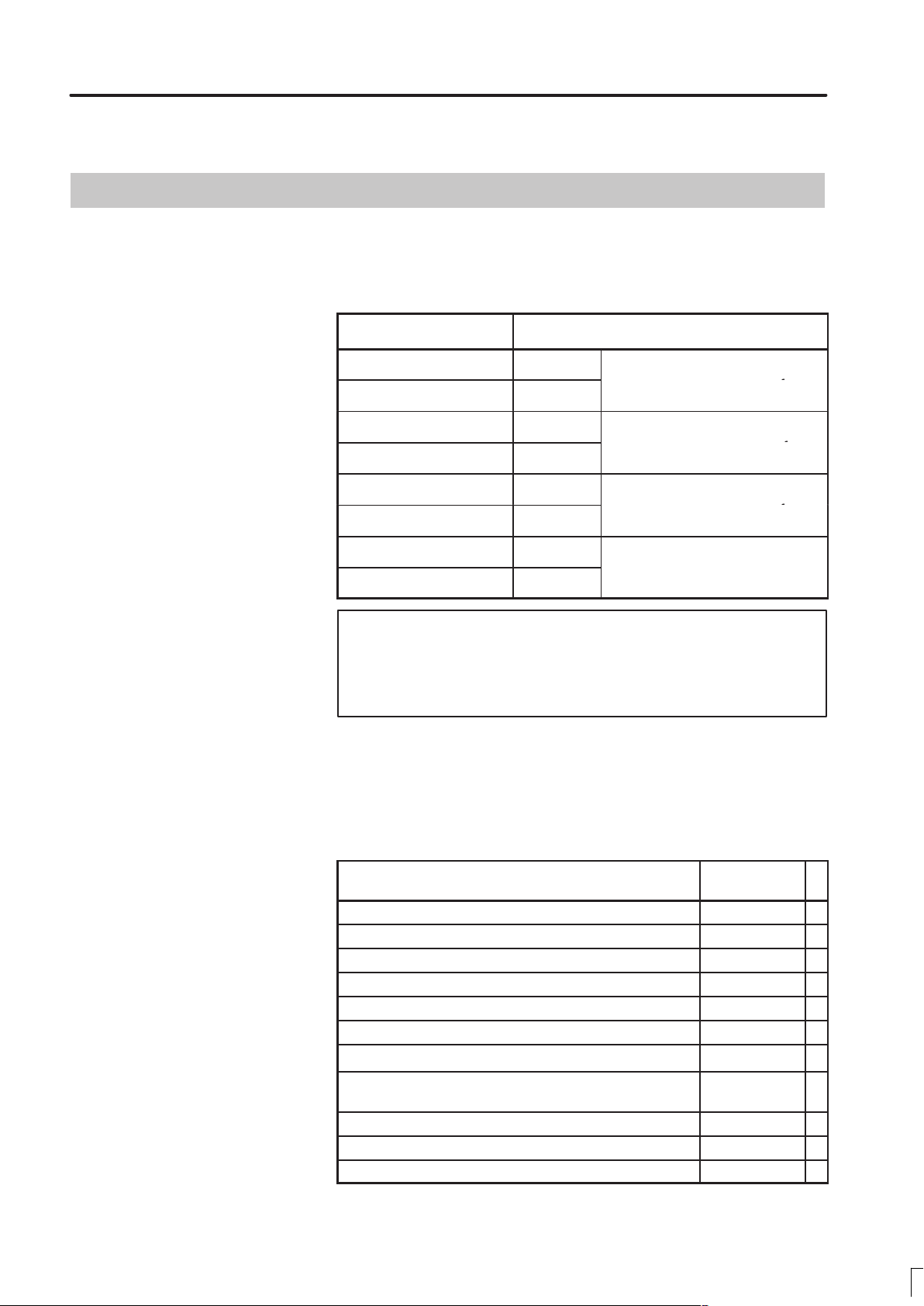
The mode covered by this manual, and their abbreviations are :
Product Name Abbreviations
FANUC Series 16–TC 16–TC
FANUC Series 160–TC 160–TC
FANUC Series 16–MC 16–MC
FANUC Series 160–MC 160–MC
FANUC Series 18–TC 18–TC
FANUC Series 180–TC 180–TC
FANUC Series 18–MC 18–MC
FANUC Series 180–MC 180–MC
T series or
T series (two–path control) *
M series or
M series (two–path control) *
T series or
T series (two–path control) *
1
1
1
Note
Some functions described in this manual may not be
applied to some products.
For details, refer to the DESCRIPTIONS (B–62752JA).
The table below lists manuals related to MODEL C of Series 16, Series
18, Series 160, Series 180. In the table, this manual is maked with an
asterisk (*).
Table 1 Related manuals
Manual name
DESCRIPTIONS B–62752EN
CONNECTION MANUAL (Hardware) B–62753EN
CONNECTION MANUAL (Function) B–62753EN–1
OPERATOR’S MANUAL FOR LATHE B–62754EN
OPERATOR’S MANUAL FOR MACHINE CENTER B–62764EN
MAINTENANCE MANUAL B–62755EN
PARAMETER MANUAL B–62760EN
PROGRAMMING MANUAL
(Macro Compiler/Macro Executer)
FAPT MACRO COMPILER PROGRAMMING MANUAL B–66102E
FANUC Super CAP T OPERATOR’S MANUAL B–62444E–1
FANUC Super CAP M OPERATOR’S MANUAL B–62154E
Specification
Number
B–61803E–1
*
Page 4

PREFACE
B–62760EN/01
Table 1 Related manuals
Manual name
FANUC Super CAP M PROGRAMMING MANUAL B–62153E
CONVERSATIONAL AUTOMATIC PROGRAMMING
FUNCTION I FOR LATHE OPERATOR’S MANUAL
CONVERSATIONAL AUTOMATIC PROGRAMMING
FUNCTION FOR LATHE OPERATOR’S MANUAL
Specification
Number
B–61804E–1
B–61804E–2
Page 5

B–62760EN/01
Table of contents
1. DISPLAYING PARAMETERS 1. . . . . . . . . . . . . . . . . . . . . . . . . . . . . . . . . . . . . . . . . . . .
2. SETTING PARAMETERS FROM MDI 3. . . . . . . . . . . . . . . . . . . . . . . . . . . . . . . . . . . .
3. INPUTTING AND OUTPUTTING PARAMETERS THROUGH
THE READER/PUNCHER INTERFACE 5. . . . . . . . . . . . . . . . . . . . . . . . . . . . . . . . . . .
3.1 OUTPUTTING PARAMETERS THROUGH THE READER/PUNCHER INTERF ACE 6. . . . . . . . .
3.2 INPUTTING PARAMETERS THROUGH THE READER/PUNCHER INTERFACE 7. . . . . . . . . . .
4. DESCRIPTION OF PARAMETERS 8. . . . . . . . . . . . . . . . . . . . . . . . . . . . . . . . . . . . . . .
4.1 PARAMETERS OF SETTING 10. . . . . . . . . . . . . . . . . . . . . . . . . . . . . . . . . . . . . . . . . . . . . . . . . . . . . . .
4.2 PARAMETERS OF READER/PUNCHER INTERFACE, REMOTEBUFFER,
DNC1, DNC2, AND M–NET INTERF ACE 14. . . . . . . . . . . . . . . . . . . . . . . . . . . . . . . . . . . . . . . . . . . .
4.3 PARAMETERS OF AXIS CONTROL/ INCREMENT SYSTEM 32. . . . . . . . . . . . . . . . . . . . . . . . . . .
4.4 PARAMETERS OF COORDLNATES 48. . . . . . . . . . . . . . . . . . . . . . . . . . . . . . . . . . . . . . . . . . . . . . . .
4.5 PARAMETERS OF STROKE LIMIT 53. . . . . . . . . . . . . . . . . . . . . . . . . . . . . . . . . . . . . . . . . . . . . . . . .
4.6 PARAMETERS OF THE CHUCK AND TAILSTOCK BARRIER (16–TB) 56. . . . . . . . . . . . . . . . . . .
4.7 PARAMETERS OF FEEDRATE 60. . . . . . . . . . . . . . . . . . . . . . . . . . . . . . . . . . . . . . . . . . . . . . . . . . . . .
4.8 PARAMETERS OF ACCELERATION/ DECELERATION CONTROL 72. . . . . . . . . . . . . . . . . . . . . .
4.9 PARAMETERS OF SERVO 90. . . . . . . . . . . . . . . . . . . . . . . . . . . . . . . . . . . . . . . . . . . . . . . . . . . . . . . .
4.10 PARAMETERS OF DI/DO 106. . . . . . . . . . . . . . . . . . . . . . . . . . . . . . . . . . . . . . . . . . . . . . . . . . . . . . . . .
4.11 PARAMETERS OF CRT/MDI, DISPLAY, AND EDIT 110. . . . . . . . . . . . . . . . . . . . . . . . . . . . . . . . . . .
4.12 PARAMETERS OF PROGRAMS 128. . . . . . . . . . . . . . . . . . . . . . . . . . . . . . . . . . . . . . . . . . . . . . . . . . . .
4.13 PARAMETERS OF PITCH ERROR COMPENSATION 136. . . . . . . . . . . . . . . . . . . . . . . . . . . . . . . . . .
4.14 PARAMETERS OF SPINDLE CONTROL 141. . . . . . . . . . . . . . . . . . . . . . . . . . . . . . . . . . . . . . . . . . . . .
4.15 PARAMETERS OF TOOL COMPENSATION 177. . . . . . . . . . . . . . . . . . . . . . . . . . . . . . . . . . . . . . . . . .
4.16 PARAMETERS RELATED TO GRINDING–WHEEL WEAR COMPENSATION 185. . . . . . . . . . . . .
4.17 PARAMETERS OF CANNED CYCLES 186. . . . . . . . . . . . . . . . . . . . . . . . . . . . . . . . . . . . . . . . . . . . . .
4.18 PARAMETERS OF RIGID TAPPING 197. . . . . . . . . . . . . . . . . . . . . . . . . . . . . . . . . . . . . . . . . . . . . . . . .
4.19 PARAMETERS OF SCALING/COORDINATE ROTATION 210. . . . . . . . . . . . . . . . . . . . . . . . . . . . . . .
4.20 PARAMETERS OF UNI–DIRECTIONAL POSITIONING 212. . . . . . . . . . . . . . . . . . . . . . . . . . . . . . . .
4.21 PARAMETERS OF POLAR COORDINATE INTERPOLATION 213. . . . . . . . . . . . . . . . . . . . . . . . . . .
4.22 PARAMETERS OF NORMAL DIRECTION CONTROL 215. . . . . . . . . . . . . . . . . . . . . . . . . . . . . . . . .
4.23 PARAMETERS OF INDEXING INDEX TABLE 217. . . . . . . . . . . . . . . . . . . . . . . . . . . . . . . . . . . . . . . .
4.24 PARAMETER FOR INVOLUTE INTERPOLATION 219. . . . . . . . . . . . . . . . . . . . . . . . . . . . . . . . . . . .
4.25 EXPONENTIAL INTERPOLATION PARAMETERS 220. . . . . . . . . . . . . . . . . . . . . . . . . . . . . . . . . . . .
4.26 STRAIGHTNESS COMPENSATION PARAMETERS 221. . . . . . . . . . . . . . . . . . . . . . . . . . . . . . . . . . .
4.27 PARAMETERS OF CUSTOM MACROS 223. . . . . . . . . . . . . . . . . . . . . . . . . . . . . . . . . . . . . . . . . . . . . .
4.28 PARAMETERS RELATED TO PATTERN DATA INPUT 230. . . . . . . . . . . . . . . . . . . . . . . . . . . . . . . . .
4.29 PARAMETER OF SKIP FUNCTION 231. . . . . . . . . . . . . . . . . . . . . . . . . . . . . . . . . . . . . . . . . . . . . . . . .
4.30 PARAMETERS OF AUTOMATIC TOOL COMPENSATION (16–TB)
AND AUTOMATIC TOOL LENGTH COMPENSATION (16–MB) 236. . . . . . . . . . . . . . . . . . . . . . . . .
4.31 PARAMETER OF EXTERNAL DATA INPUT/OUTPUT 238. . . . . . . . . . . . . . . . . . . . . . . . . . . . . . . . .
4.32 PARAMETERS OF GRAPHIC DISPLAY 238. . . . . . . . . . . . . . . . . . . . . . . . . . . . . . . . . . . . . . . . . . . . .
4.33 PARAMETERS OF DISPLAYING OPERATION TIME AND NUMBER OF PARTS 243. . . . . . . . . . .
i
Page 6

Table of contents
4.34 PARAMETERS OF TOOL LIFE MANAGEMENT 246. . . . . . . . . . . . . . . . . . . . . . . . . . . . . . . . . . . . . .
4.35 PARAMETERS OF POSITION SWITCH FUNCTIONS 249. . . . . . . . . . . . . . . . . . . . . . . . . . . . . . . . . .
4.36 PARAMETERS OF MANUAL OPERATIONAND AUT OMATIC OPERATION 252. . . . . . . . . . . . . .
4.37 PARAMETERS OF MANUAL HANDLE FEED, HANDLE INTERRUPTION
AND HANDLE FEED IN TOOL AXIAL DIRECTION 253. . . . . . . . . . . . . . . . . . . . . . . . . . . . . . . . . .
4.38 PARAMETERS RELATED TO BUTT–TYPE REFERENCE POSITION SETTING 257. . . . . . . . . . . .
4.39 PARAMETERS OF SOFTWARE OPERATOR’S PANEL 259. . . . . . . . . . . . . . . . . . . . . . . . . . . . . . . . .
4.40 PARAMETERS OF PROGRAM RESTART 262. . . . . . . . . . . . . . . . . . . . . . . . . . . . . . . . . . . . . . . . . . . .
4.41 PARAMETERS OF HIGH–SPEED MACHINING
(HIGH–SPEED CYCLE MACHINING/HIGH– SPEED REMOTE BUFFER) 263. . . . . . . . . . . . . . . . .
4.42 PARAMETERS OF POLYGON TURNING 266. . . . . . . . . . . . . . . . . . . . . . . . . . . . . . . . . . . . . . . . . . . .
4.43 PARAMETERS OF THE EXTERNAL PULSE INPUT 270. . . . . . . . . . . . . . . . . . . . . . . . . . . . . . . . . . .
4.44 PARAMETERS OF THE HOBBING MACHINE AND ELECTRONIC GEAR BOX 271. . . . . . . . . . .
4.45 PARAMETERS OF AXIS CONTROL BY PMC 276. . . . . . . . . . . . . . . . . . . . . . . . . . . . . . . . . . . . . . . .
4.46 PARAMETERS OF TWO–PATH CONTROL 281. . . . . . . . . . . . . . . . . . . . . . . . . . . . . . . . . . . . . . . . . . .
4.47 PARAMETERS FOR CHECKING INTERFERENCE BETWEEN TOOL POSTS
(TWO–PATH CONTROL) 282. . . . . . . . . . . . . . . . . . . . . . . . . . . . . . . . . . . . . . . . . . . . . . . . . . . . . . . . . .
4.48 PARAMETERS RELA TED T O PATH AXIS REASSIGNMENT 284. . . . . . . . . . . . . . . . . . . . . . . . . . .
4.49 PARAMETERS FOR ANGULAR AXIS CONTROL 296. . . . . . . . . . . . . . . . . . . . . . . . . . . . . . . . . . . . .
4.50 PARAMETERS RELATED TO B–AXIS CONTROL 297. . . . . . . . . . . . . . . . . . . . . . . . . . . . . . . . . . . .
4.51 PARAMETERS OF SIMPLE SYNCHRONOUS CONTROL 301. . . . . . . . . . . . . . . . . . . . . . . . . . . . . .
4.52 PARAMETERS OF RELATED TO CHECK TERMINATION 306. . . . . . . . . . . . . . . . . . . . . . . . . . . . .
4.53 CHOPPING PARAMETERS 307. . . . . . . . . . . . . . . . . . . . . . . . . . . . . . . . . . . . . . . . . . . . . . . . . . . . . . . .
4.54 PARAMETERS OF HIGH–SPEED HIGH–PRECISION CONTOUR CONTROL BY
RISC (16–MB) 310. . . . . . . . . . . . . . . . . . . . . . . . . . . . . . . . . . . . . . . . . . . . . . . . . . . . . . . . . . . . . . . . . . .
4.55 OTHER PARAMETERS 317. . . . . . . . . . . . . . . . . . . . . . . . . . . . . . . . . . . . . . . . . . . . . . . . . . . . . . . . . . .
4.56 PARAMETERS FOR MAINTENANCE 320. . . . . . . . . . . . . . . . . . . . . . . . . . . . . . . . . . . . . . . . . . . . . . .
B–62760EN/01
APPENDIXES
A. CHARACTER CODE LIST 321. . . . . . . . . . . . . . . . . . . . . . . . . . . . . . . . . . . . . . . . . . . . . .
ii
Page 7
B–62760EN/01
1
1. DISPLA YING PARAMETERS
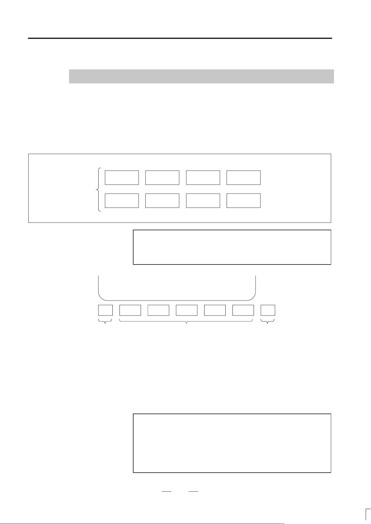
DISPLAYING PARAMETERS
Follow the procedure below to display parameters.
(1) Press the SYSTEM function key on the CRT/MDI as many times as
required, or alternatively , press the SYSTEM function key once, then
the PARAM section select soft key. The parameter screen is then
selected.
Function keys
POS PROG
SYSTEM MESSAGE GRAPH
Note
Pressing the SYSTEM function key displays section select
soft keys including PARAM.
>
MEM STRT MTN FIN *** 10:02:30
[ PARAM ] [ DGNOS ] [ PMC ] [ SYSTEM ] [ (OPRT) ]
Return menu key Soft keys Continuous menu key
(2 ) The parameter screen consists of multiple pages. Use step (a) or (b)
to display the page that contains the parameter you want to display.
(a) Use the page select key or the cursor move keys to display the de-
sired page.
(b) Enter the data number of the parameter you want to display from
the keyboard, then press the [NO.SRH] soft key . The parameter
page containing the specified data number appears with the cursor positioned at the data number. (The data is displayed in reverse video.)
OFFSET
SETTING
CUSTOM
Soft key display
←
(section select)
Note
If key entry is started with the section select soft keys
displayed, they are replaced automatically by operation
select soft keys including [NO.SRH]. Pressing the
[(OPRT)] soft key can also cause the operation select
keys to be displayed.
1
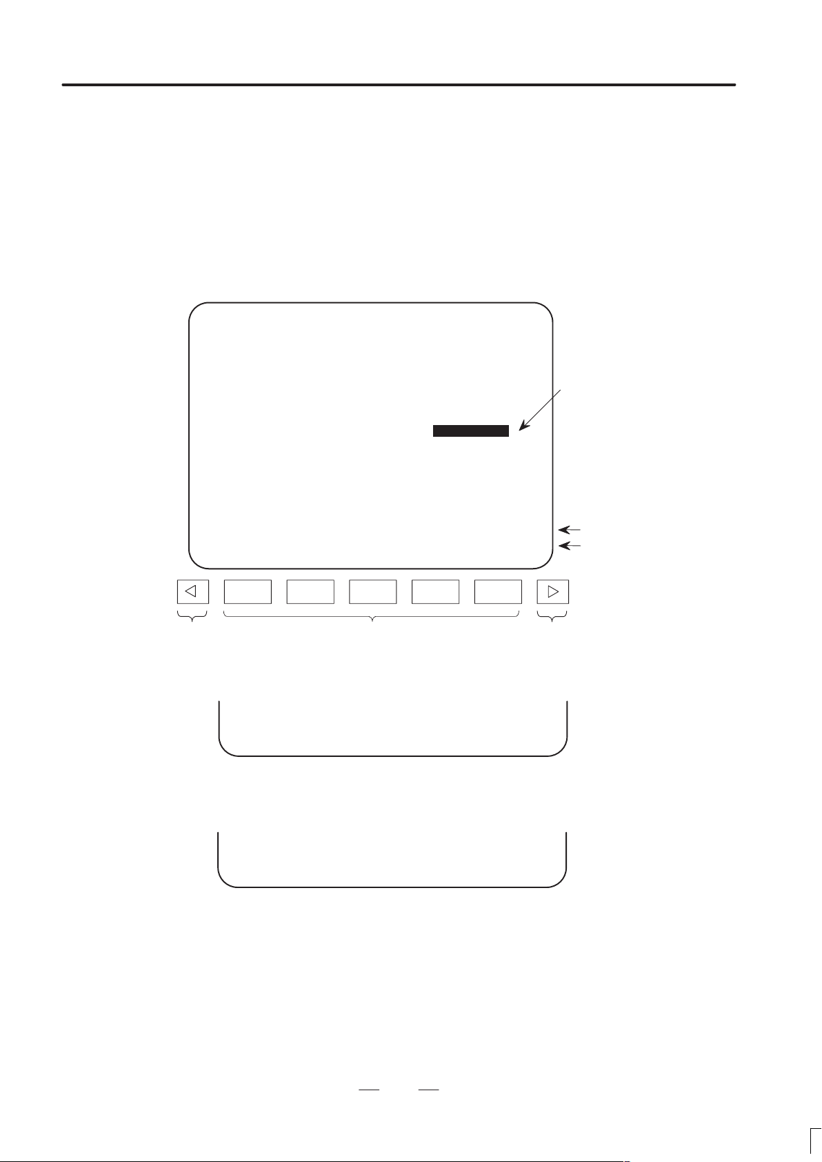
Page 8

1. DISPLA YING PARAMETERS
B–62760EN/01
>
MEM STRT MTN FIN *** 10:02:34
[ NO. SRH ] [ ON:1 ] [ OFF:0 ] [ +INPUT ] [ INPUT ]
PARAMETER (FEEDRATE)
1401 RDR JZR RPD
00000000
1402 JRV
00000000
1410 DRY RUN FEEDRATE
1412 0
1420 RAPID FEEDRATE X 15000
>
MEM STRT MTN FIN *** 10:02:35
[ NO. SRH ] [ ON:1 ] [ OFF:0 ] [ +INPUT ] [ INPUT ]
Data entered from
←
the keyboard
Soft key display
←
(section select)
O0001 N00010
10000
Y 15000
Z 15000
Cursor
2
Page 9

B–62760EN/01
2
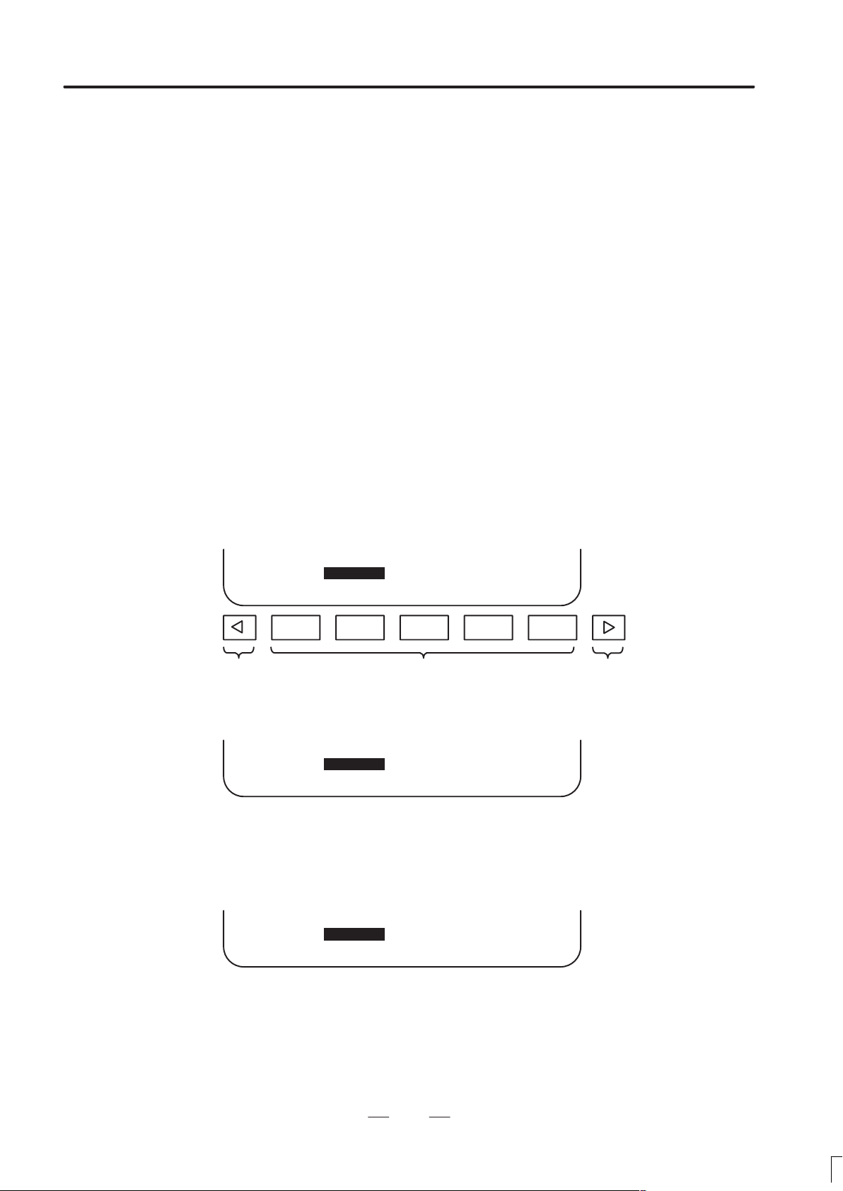
2. SETTING PARAMETERS FROM MDI
SETTING PARAMETERS FROM MDI
Follow the procedure below to set parameters.
(1) Place the NC in the MDI mode or the emergency stop state.
(2) Follow the substeps below to enable writing of parameters.
1. To display the setting screen, press the SETTING function key
as many times as required, or alternatively press the SETTING
function key once, then the SETTING section select soft key . The
first page of the setting screen appears.
2. Position the cursor on “P ARAMETER WRITE” using the cursor
move keys.
SETTING (HANDY) O0001 N00010
PARAMETER WRITE = (0:DISABLE 1:ENABLE)
TV CHECK = 0 (0:OFF 1:ON)
PUNCH CODE = 0 (0:EIA 1:ISO)
INPUT UNIT = 0 (0:MM 1:INCH)
I/O CHANNEL = 0 (0–3:CHANNEL NO.)
3. Press the [(OPRT)] soft key to display operation select soft keys.
> 1410
MDI STOP *** *** *** 10:03:02
[ NO. SRH ] [ ON:1 ] [ OFF:0 ] [ +INPUT ] [ INPUT ]
4. To set “PARAMETER WRITE=” to 1, press the ON:1 soft key,
or alternatively enter 1 and press the INPUT soft key . From now
on, the parameters can be set. At the same time an alarm condition (P/S100 PARAMETER WRITE ENABLE) occurs in the
CNC.
(3 ) To display the parameter screen, press the SYSTEM function key as
many times as required, or alternatively press the SYSTEM function
key once, then the PARAM section select soft key.
(See “1. Displaying Parameters.”)
(4) Display the page containing the parameter you want to set, and
position the cursor on the parameter. (See “1. Displaying
Parameters.”)
0
← Data entered from
the keyboard
← Soft key display
(section select)
(5 ) Enter data, then press the [INPUT] soft key. The parameter indicated
by the cursor is set to the entered data.
3
Page 10

L2. SETTING P ARAMETERS FROM MDI
[Example] 12000 [INPUT]
Data can be entered continuously for parameters, starting at the selected
parameter, by separating each data item with a semicolon (;).
[Example]
PARAMETER (FEEDRATE) O0001 N00010
1401 RDR JZR RPD
00000000
1402 JRV
00000000
1410 DRY RUN FEEDRATE
1412 0
1420 RAPID FEEDRATE X 15000
>
MDI STOP *** *** ALM 10:03:10
[ NO. SRH ] [ ON:1 ] [ OFF:0 ] [ +INPUT ] [ INPUT ]
12000
Y 15000
Z 15000
B–62760EN/01
Cursor
Entering 10;20;30;40 and pressing the INPUT key assigns values 10, 20,
30, and 40 to parameters in order starting at the parameter indicatedby the
cursor.
(6) Repeat steps (4) and (5) as required.
(7) If parameter setting is complete, set “PARAMETER WRITE=” to 0
on the setting screen to disable further parameter setting.
(8) Reset the NC to release the alarm condition (P/S100).
If an alarm condition (P/S000 PLEASE TURN OFF POWER) occurs in
the NC, turn it off before continuing operation.
Note
The bits left blank in 4. DESCRIPTION OF
PARAMETERS and the parameter numbers that appear
on the CRT screen but are not found in the parameter list
are reserved for future expansion. They must always be
0.
4
Page 11

B–62760EN/01
3
3. INPUTTING AND OUTPUTTING PARAMETERS THROUGH
THE READER/PUNCHER INTERFACE
INPUTTING AND OUTPUTTING PARAMETERS THROUGH THE
READER/PUNCHER INTERFACE
This section explains the parameter input/output procedures for
input/output devices connected to the reader/puncher interface.
The following description assumes the input/output devices are ready for
input/output. It also assumes parameters peculiar to the input/output
devices, such as the baud rate and the number of stop bits, have been set in
advance.
5
Page 12
3. INPUTTING AND OUTPUTTING PARAMETERS THROUGH
THE READER/PUNCHER INTERFACE
3.1
B–62760EN/01
OUTPUTTING
PARAMETERS
THROUGH THE
READER/PUNCHER
INTERFACE
PARAMETER (FEEDRATE) O0001 N00010
1401 RDR JZR RPD
1402 JRV
1410 DRY RUN FEEDRATE
1412 0
1420 RAPID FEEDRATE X 15000
>
MDI STOP *** *** ALM 10:03:10
[ NO. SRH ] [ ON:1 ] [ OFF:0 ] [ +INPUT ] [ INPUT ]
(1) Select the EDIT mode.
(2) To select the parameter screen, press the SYSTEM function key as
many times as required, or alternatively press the SYSTEM function
key once, then the PARAM section select soft key.
(3 ) Press the [(OPRT)] soft key to display operation select soft keys, then
press the forward menu key located at the right–hand side of the soft
keys to display another set of operation select keys including
PUNCH.
00000000
00000000
12000
Y 15000
Z 15000
Cursor
State display
Soft key display (operation
select)
Soft keys Continuous menu keyReturn menu key
(4) Pressing the [PUNCH] soft key changes the soft key display as
shown below:
>
EDIT STOP *** *** *** 10:35:03
[ ] [ ] [ ] [ CANCEL ] [ EXEC ]
(5) Press the [EXEC] soft key to start parameter output. When
parameters are being output, “OUTPUT” blinks in the state display
field on the lower part of the screen.
>
EDIT STOP *** *** *** 10:35:04 OUTPUT
[ ] [ ] [ ] [ CANCEL ] [ EXEC ]
(6 ) When parameter output terminates, “OUTPUT” stops blinking. Press
the RESET key to interrupt parameter output.
← OUTPUT blinking
6
Page 13
B–62760EN/01
3.2
3. INPUTTING AND OUTPUTTING PARAMETERS THROUGH
THE READER/PUNCHER INTERFACE
INPUTTING
PARAMETERS
THROUGH THE
READER/PUNCHER
INTERFACE
(1) Place the NC in the emergency stop state.
(2) Enable parameter writing.
1. To display the setting screen, press the SETTING function key
as many times as required, or alternatively press the SETTING
function key once, then the SETTING section select soft key . The
first page of the setting screen appears.
2. Position the cursor on “P ARAMETER WRITE” using the cursor
move keys.
3. Press the [(OPRT)] soft key to display operation select soft keys.
4. T o set “PARAMETER WRITE=” to 1, press the ON:1 soft key,
or alternatively enter 1, then press the [INPUT] soft key. From
now on, parameters can be set. At the same time an alarm condition (P/S100 PARAMETER WRITE ENABLE) occurs in the
NC.
(3) To select the parameter screen, press the SYSTEM function key as
many times as required, or alternatively press the SYSTEM key once,
then [PARAM] soft key.
(4) Press the [(OPRT)] soft key to display operation select keys, then
press the forward menu key located at the right–hand side of the soft
keys to display another set of operation select soft keys including
[READ].
>
EDIT STOP ALM 10:37:30
[ ] [ READ ] [ PUNCH ] [ ] [ ]
EMS
← State display
← Soft key display
Soft keys Continuous menu key
(5 ) Pressing the [READ] soft key changes the soft key display as shown
below:
>
EDIT STOP ALM 10:37:30
[ ] [ ] [ ] [ CANCEL ] [ EXEC ]
EMS
(6) Press the [EXEC] soft key to start inputting parameters from the
input/output device. When parameters are being input, “INPUT”
blinks in the state display field on the lower part of the screen.
>
EDIT STOP ALM 10:37:30 INPUT
[ ] [ ] [ ] [ CANCEL ] [ EXEC ]
EMS
(7 ) When parameter input terminates, “INPUT” stops blinking. Press the
RESET key to interrupt parameter input.
(8) When parameter read terminates, “INPUT” stops blinking, and an
alarm condition (P/S000) occurs in the NC. Turn it off before
continuing operation.
← INPUT blinking
7
Page 14
4. DESCRIPTION OF P ARAMETERS
0 or 1
g
g
0
99999999
DESCRIPTION OF PARAMETERS
4
Parameters are classified by data type as follows:
Table 4 Data Types and Valid Data Ranges of Parameters
Data type Valid data range Remarks
Bit
Bit axis
Byte
Byte axis
Word
Word axis
2–word
2–word axis
0 – 127
0 – 255
0 – 32767
0 – 65535
–
–
In some parameters, signs are
ignored.
In some parameters, signs are
ignored.
B–62760EN/01
[Example]
0000
Data No.
1023 Servo axis number of a specific axis
Notes
1 For the bit type and bit axis type parameters, a single data
number is assigned to 8 bits. Each bit has a different
meaning.
2 The axis type allows data to be set separately for each
control axis.
3 The valid data range for each data type indicates a
general range. The range varies according to the
parameters. For the valid data range of a specific
parameter, see the explanation of the parameter.
(1) Notation of bit type and bit axis type parameters
#7
#6 #5
SEQ
#4 #3 #2
Data #0 to #7 are bit positions.
INI
#1
ISO
(2) Notation of parameters other than bit type and bit axis type
#0
TVC
Data No.
8
Data.
Page 15

B–62760EN/01
4. DESCRIPTION OF P ARAMETERS
Notes
1 The systems may be classified as follows:
T series : 16/18/160/180–TC
M series : 16/18/160/180–MC
2–path control:with an option of 2–path control
2 Parameters having different meanings between the T
series and M series and parameters that are valid only for
the T or M series are indicated in two levels as shown
below. Parameters left blank are unavailable.
Example1
Example2
Example3
Parameter 5010 has different meanings for the T series and M series.
5010
Tool nose radius compensation ...
Tool compensation C ...
DPI is a parameter common to the M and T series, but GSB and GSC are
parameters valid only for the T series.
#7 #6 #0
3401
GSC GSB DPI
DPI
The following parameter is provided only for the M series.
1450
F1 digit feed ...
T series
M series
T series
M series
T series
M series
9
Page 16

4. DESCRIPTION OF P ARAMETERS
4.1
PARAMETERS OF
SETTING
B–62760EN/01
#7
0000
#6 #5
SEQ
Setting entry is acceptable.
[Data type] Bit
TVC TV check
0 : Not performed
1 : Performed
ISO Code used for data output
0 : EIA code
1 : ISO code
INI Unit of input
0 : In mm
1 : In inches
SEQ Automatic insertion of sequence numbers
0: Not performed
1: Performed
Note
When a program is prepared by using MDI keys in the
part program storage and edit mode, a sequence number
can automatically be assigned to each block in set
increments. Set the increment to parameter 3216.
#4 #3 #2
INI
#1
ISO
#0
TVC
0001
Setting entry is acceptable.
[Data type] Bit
FCV Tape format
0: Series 16 standard format
1: Series 15 format
#7
#6 #5 #4 #3 #2 #1
10
#0
FCV
Page 17

B–62760EN/01
4. DESCRIPTION OF P ARAMETERS
Notes
Programs created in the Series 15 tape format can be
used for operation on the following functions:
1 Subprogram call M98
2 Thread cutting with equal leads G32 (T series)
3 Canned cycle G90, G92, G94 (T series)
4 Multiple repetitive canned cycle G71 to G76 (T series)
5 Drilling canned cycle G73, G74, G76, G80 to G89 (M
series)
6 Cutter compensation C (M series)
When the tape format used in the Series 15 is used for
this CNC, some limits may add. Refer to the Series 16/18
/160/180–MODEL C OPERATOR’S MANUAL
(B–62754EN (16/18/160/180–TC), or B–62764EN
(16/18/160/180–MC)).
0002
Setting entry is acceptable.
[Data type] Bit
RDG Remote diagnose
0 : Not performed
1 : Performed
Note
Set this bit to 0 when the remote diagnosis functions is not
used. When this bit is set to 1, never modify the
parameters related to remote diagnosis (parameter Nos.
0201 to 0223).
SJZ Manual reference position si performed as follows:
0 : When no reference position has been set, reference position return is
performed using deceleration dogs. When a reference position is
already set, reference position return is performed using rapid traverse
and deceleration dogs are ignored.
1 : Reference position return is performed using deceleration dogs at all
times.
#7
#6 #5 #4 #3 #2 #1 #0
RDG
RDGSJZ
Note
SJZ is enabled when bit 3 (HJZ) of parameter No. 1005 is
set to 1. When a reference position is set without a dog,
(i.e. when bit 1 (DLZ) of parameter No. 1002 is set to 1 or
bit 1 (DLZx) of parameter No. 1005 is set to 1) reference
position return after reference position setting is
performed using rapid traverse at all times, regardless of
the setting of SJZ.
11
Page 18

4. DESCRIPTION OF P ARAMETERS
B–62760EN/01
#7
RMVx0012
#6 #5 #4 #3 #2 #1 #0
Setting entry is acceptable.
[Data type] Bit axis
MIRx Mirror image for each axis
0 : Mirror image is off.
1 : Mirror image is on.
RMVx Releasing the assignment of the control axis for each axis
0 : Not released
1 : Released
Note
RMVx is valid when RMBx in parameter 1005 is 1.
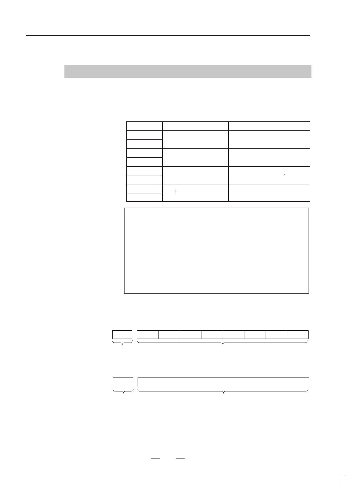
0020 I/O CHANNEL: Selection of an input/output device
Setting entry is acceptable.
MIRx
[Data type] Byte
[Valid data range] 0 to 35
This CNC provides the following interfaces for data transfer to and from
the host computer and external input/output devices:
– Input/output device interface (RS–232–C serial port)
– Remote buffer interface (RS–232–C/RS–422)
– DNC1/DNC2 interface
In addition, data can be transferred to and from the Power Mate via the
FANUC I/O Link.
This parameter is used to select the interface used to trnsfer data to and
from an input/output device.
Notes
1 The input/output device used can be selected also on the
setting screen. Using the setting screen is a more
common method for selecting the device.
2 The specified data, such as a baud rate and the number
of stop bits, of an input/output device connected to a
specific channel must be set in parameters for that
channel in advance.
I/O CHANNEL=0 and I/O CHANNEL=1 both refer to
channel 1. For each, parameters to set the baud rate, the
number of stop bits, and other data are provided
separately.
12
Page 19
B–62760EN/01
21
Group 1
|
15) via the FANUC I/O Link
Grou 14
4. DESCRIPTION OF P ARAMETERS
Setting Description
0, 1 RS–232–C serial port (connector JD5A on the main CPU board)
2 RS–232–C serial port (connectior JD5B on the main CPU board)
3 Remote buffer interface (connector JD5C (RS–232–C interface) or
connector JD6A (RS–422 interface) on option 1 board)
5 Data server board
10 DNC1/DNC2 interface, OSI–Ethernet
11 DNC1 interafce #2
20
Group 0
22
34
35
p
Group 2
|
Group 14
Group 15
Data is transferred between the CNC and Power Mate
in group n (n: 0 to
.
Notes
1 An input/output device can also be selected using the
setting screen. Usually the setting screen is used.
2 Secifications (such as the baud rate and number of stop
bits) of input/output devices to be connected neet to be
set in the corresponding paremeters for each interface
beforehand. (See Section 4.2) I/O channel = 0 and I/O
channel = 1 represent input/output devices connected to
RS–232–C serial port 1. However, separate parameters
for the baud rate, stop bits, and other specifications are
provided for each channel.
Series 16/18/160/180–C
MAIN CPU BOARD OPTION- 1 BOARD
Channel 1
JD5A
RS–232–C
Reader/puncher
I/ O CHANNEL=0 I/ O CHANNEL=2 I/ O CHANNEL=3 I/ O CHANNEL=3
or
I/ O CHANNEL=1
JD5B
RS–232–C RS–232–C RS–422
Reader/puncher
Fig.4.1 I/O Unit Selection
Channel 3Channel 2
JD5C JD6A
Host computer
Host computer
13
Page 20

4. DESCRIPTION OF P ARAMETERS
B–62760EN/01
4.2
PARAMETERS OF
READER/PUNCHER
INTERFACE, REMOTE
BUFFER, DNC1,
DNC2, AND M–NET
INTERFACE
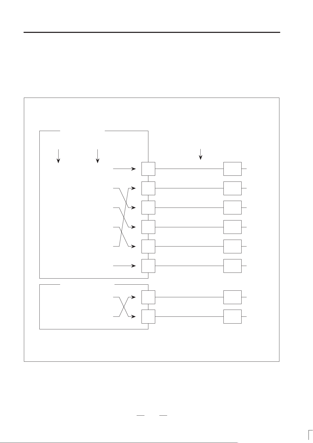
Input/output channel number (parameter No. 0020)
0020 0101
Specify a channel for an input/output device.
I/ O CHANNEL
=0 : Channel1
=1 : Channel1
=2 : Channel2
=3 : Channel3
I/O CHANNEL
This CNC has three channels of input/output device interfaces. The
input/output device to be used is specified by setting the channel
connected to that device in setting parameter I/O CHANNEL.
The specified data, such as a baud rate and the number of stop bits, of an
input/output device connected to a specific channel must be set in
parameters for that channel in advance.
For channel 1, two combinations of parameters to specify the input/output
device data are provided.
The following shows the interrelation between the input/output device
interface parameters for the channels.
↓
Stop bit and other data
I/O CHANNEL=0
(channel 1)
I/O CHANNEL=1
(channel 1)
0102
0103
01 11
01 12
01 13
Number specified for the input/
output device
Baud rate
Stop bit and other data
Number specified for the input/
output device
Baud rate
0121
I/O CHANNEL=2
(channel 2)
I/O CHANNEL=3
(channel 3)
Fig.4.2 I/O Device Interface Settings
0122
0123
0131
0132
0133
0134
0135
Stop bit and other data
Number specified for the input/
output device
Baud rate
Stop bit and other data
Number specified for the input/
output device
Baud rate
Selection of protocol
Selection of RS–422 or
RS–232C, and other data
14
Page 21

B–62760EN/01
4. DESCRIPTION OF P ARAMETERS
(1) Parameters common to all channels
#7
ENS0100
#6
IOP
#5
ND3
#4 #3
NCR
#2 #1
CTV
Setting entry is acceptable.
[Data type] Bit
CTV: Character counting for TV check in the comment section of a program.
0 : Performed
1 : Not performed
NCR Output of the end of block (EOB) in ISO code
0 : LF, CR, CR are output.
1 : Only LF is output.
ND3 In DNC operation, a program is:
0 : Read block by block. (A DC3 code is output for each block.)
1 : Read continuously until the buffer becomes full. (A DC3 code is
output when the buffer becomes full.)
Note
In general, reading is performed more efficiently when
ND3 = 1. This specification reduces the number of
buffering interruptions caused by reading of a series of
blocks specifying short movements. This in turn reduces
the effective cycle time.
#0
IOP Specifies how to stop NC program input/output operations.
0 : An NC reset can stop NC program input/output operations.
1 : Only the [STOP] soft key can stop NC program input/output
operations. (An NC reset cannot stop NC program input/output
operations.)
ENS Action taken when a NULL code is found during read of EIA code
0 : An alarm is generated.
1 : The NULL code is ignored.
(2) Parameters for channel 1 (I/O CHANNEL=0)
#7
NFD0101
#6 #5 #4 #3
ASI
#2 #1 #0
[Data type] Bit type
SB2 The number of stop bits
0 : 1
1 : 2
ASI Code used at data input
0 : EIA or ISO code (automatically distinguished)
1 : ASCII code
NFD Feed before and after the data at data output
0 : Output
1 : Not output
SB2
Note
When input/output devices other than the FANUC PPR
are used, set NFD to 1.
15
Page 22

4. DESCRIPTION OF P ARAMETERS
B–62760EN/01
0102
[Data type] Byte
Set the number specified for the input/output device used when the I/O
CHANNEL is set to 0, with one of the set values listed in Table 4.2 (a).
Set value
Number specified for the input/output device (when the I/O CHANNEL is set to
0)
Table 4.2 (a) Set value and Input/Output Device
Input/output device
0 RS–232–C (Used control codes DC1 to DC4)
1 FANUC CASSETTE ADAPTOR 1 (FANUC CASSETTE B1/ B2)
2 FANUC CASSETTE ADAPTOR 3 (FANUC CASSETTE F1)
3 FANUC PROGRAM FILE Mate, FANUC FA Card Adaptor
FANUC FLOPPY CASSETTE ADAPTOR, FANUC Handy File
FANUC SYSTEM P-MODEL H
4 RS–232–C (Not used control codes DC1 to DC4)
5 Portable tape reader
6 FANUC PPR
FANUC SYSTEM P-MODEL G, FANUC SYSTEM P-MODEL H
0103 Baud rate (when the I/O CHANNEL is set to 0)
[Data type] Byte
Set baud rate of the input/output device used when the I/O CHANNEL is
set to 0, with a set value in Table 4.2 (b).
(3) Parameters for channel 1 (I/O CHANNEL=1)
[Data type] Bit
Set value Baud rate (bps)
1
2
3
4
5
6
#7
NFD0111
50
100
110
150
200
300
#6 #5 #4 #3
Table 4.2 (b)
Set value Baud rate (bps)
7
8
9
10
11
12
#2 #1 #0
ASI
600
1200
2400
4800
9600
19200
SB2
These parameters are used when I/O CHANNEL is set to 1. The meanings
of the bits are the same as for parameter 0101.
16
Page 23

B–62760EN/01
0112 Number specified for the input/output device (when I/O CHANNEL is set to 1)
[Data type] Byte
Set the number specified for the input/output device used when the I/O
CHANNEL is set to 1, with one of the set values listed in Table 4.2 (a).
0113 Baud rate (when I/O CHNNEL is set to 1)
[Data type] Byte
Set the baud rate of the input/output device used when I/O CHANNEL is
set to 1, with a value in Table 4.2 (b).
(4) Parameters for channel 2 (I/O CHANNEL=2)
[Data type] Bit
4. DESCRIPTION OF P ARAMETERS
#7
NFD0121
#6 #5 #4 #3
ASI
#2 #1 #0
SB2
These parameters are used when I/O CHANNEL is set to 2. The meanings
of the bits are the same as for parameter 0101.
0122 Number specified for the input/output device (when I/O CHANNEL is set to 2)
[Data type] Byte
Set the number specified for the input/output device used when I/O
CHANNEL is set to 2, with a value in Table 4.2 (a).
0123 Baud rate (when the I/O CHANNEL is set to 2)
[Data type] Byte
Set the baud rate of the input/output device used when I/O CHANNEL is
set to 2, with a value in Table 4.2 (b).
(5) Parameters for channel 3 (I/O CHANNEL=3)
#7
NFD0131
#6 #5 #4 #3
ASI
#2 #1 #0
SB2
[Data type] Bit
These parameters are used when I/O CHANNEL is set to 3. The meanings
of the bits are the same as for parameter 0101.
Note
When this parameter is set, the power must be turned off
before operation is continued.
17
Page 24

4. DESCRIPTION OF P ARAMETERS
0132 Number specified for the input/output device (when I/O CHANNEL is set to 3)
[Data type] Byte
0133 Baud rate (when the I/O CHANNEL is set to 3)
B–62760EN/01
Note
When this parameter is set, the power must be turned off
before operation is continued.
Set the number specified for the input/output device used when I/O
CHANNEL is set to 3, with a number in Table 4.2 (a).
Note
When this parameter is set, the power must be turned off
before operation is continued.
[Data type] Byte
Set the baud rate of the input/output device used when the I/O CHANNEL
is set to 3 according to the table 4.2 (c).
Note
Valid data range: 1 to 15 (up to a baud rate of 86400
bps) for the RS–422 interface or 1 to 12 (up to a baud
rate of 19200 bps) for the RS–232–C interface.
Table 4.2 (c) Baud Rate Settings
Set value Baud rate (bps)
1
2
3
4
5
6
7
8
50
100
110
150
200
300
600
1200
Set value Baud rate (bps)
9
10
11
12
13
14
14
2400
4800
9600
19200
38400
76800
86400
0134
#7
#6 #5
CLK#4NCD
#3 #2
SYN
#1
PRY
Note
When this parameter is set, the power must be turned off
before operation is continued.
18
#0
Page 25

B–62760EN/01
4. DESCRIPTION OF P ARAMETERS
[Data type] Bit
PRY Parity bit
0: Not used
1: Used
SYN NC reset/alarm in protocol B
0: Not reported to the host
1: Reported to the host with SYN and NAK codes
NCD CD (signal quality detection) of the RS–232–C interface
0: Checked
1: Not checked
CLK Baud rate clock when the RS–422 interface is used
0: Internal clock
1: External clock
Note
When the RS–232–C interface is used, set this bit to 0.
#7
RMS0135
#6 #5 #4 #3
Note
When this parameter is set, the power must be turned off
before operation is continued.
[Data type] Bit
ASC Communication code except NC data
0: ISO code
1: ASCII code
ETX End code for protocol A or extended protocol A
0: CR code in ASCII/ISO
1: ETX code in ASCII/ISO
Note
Use of ASCII/ISO is specified by ASC.
R42
#2
PRA
#1
ETX
#0
ASC
PRA Communication protocol
0: Protocol B
1: Protocol A
R42 Interface
0: RS–232–C interface
1: RS–422 interface
RMS State of remote/tape operation when protocol A is used
0: Always 0 is returned.
1: Contents of the change request of the remote/tape operation in the
SET command from the host is returned.
19
Page 26

4. DESCRIPTION OF P ARAMETERS
B–62760EN/01
0140
Note
[Data type] Bit
BCC The BCC value (block check characters) for the DNC2 interface is:
0: Checked.
1: Not checked.
0141 System for connection between the CNC and host (DNC1 interface)
[Data type] Byte
[Valid data range] 1 or 2
This parameter specifies the system for connection (DNC1 interface)
between the CNC and host.
Set value
1 : Point–to–point connection
2 : Multipoint connection
#7
#6 #5
BCC
#4 #3 #2 #1 #0
When this parameter is set, the power must be turned off
before operation is continued.
Note
When this parameter is set, the power must be turned off
before operation is continued.
0142 Station address of the CNC (DNC1 interface)
[Data type] Byte
[Valid data range] 2 to 52
This parameter specifies the station address of the CNC when the CNC is
connected via the DNC1 interface using multipoint connection.
Note
When this parameter is set, the power must be turned off
before operation is continued.
0143 Time limit specified for the timer monitoring a response (DNC2 interface)
Note
When this parameter is set, the power must be turned off
before operation is continued.
20
Page 27

B–62760EN/01
4. DESCRIPTION OF P ARAMETERS
[Data type] Byte
[Unit of data] Seconds
[Valid data range] 1 to 60 (The standard setting is 3.)
0144 Time limit specified for the timer monitoring the EOT signal (DNC2 interface)
Note
When this parameter is set, the power must be turned off
before operation is continued.
[Data type] Byte
[Unit of data] Seconds
[Valid data range] 1 to 60 (The standard setting is 5.)
0145 Time required for switching RECV and SEND (DNC2 interface)
Note
When this parameter is set, the power must be turned off
before operation is continued.
[Data type] Byte
[Unit of data] Seconds
[Valid data range] 1 to 60 (The standard setting is 1.)
0146 Number of times the system retries holding communication (DNC2 interface)
Note
When this parameter is set, the power must be turned off
before operation is continued.
[Data type] Byte
[Unit of data] Seconds
[Valid data range] 1 to 10 (The standard setting is 3.)
Set the maximum number of times the system retries holding
communication with the remote device if the remote device uses an
invalid protocol in the data–link layer or the remote device does not
respond to the request.
21
Page 28

4. DESCRIPTION OF P ARAMETERS
B–62760EN/01
0147
Number of times the system sends the message in response to the NAK signal
(DNC2 interface)
Note
When this parameter is set, the power must be turned off
before operation is continued.
[Data type] Byte
[Unit of data] Number of times
[Valid data range] 1 to 10 (The standard setting is 2.)
Set the maximum number of times the system retries sending the message
in response to the NAK signal.
0148 Number of characters in overrun (DNC2) interface)
Note
When this parameter is set, the power must be turned off
before operation is continued.
[Data type] Byte
[Valid data range] 10 to 225 (The standard setting is 10.)
Set the number of characters the system can receive after transmission is
stopped (CS off).
0149
Number of characters in the data section of the communication packet (DNC2
interface)
Note
When this parameter is set, the power must be turned off
before operation is continued.
[Data type] Word
[Valid range] 80 to 256
The standard setting is 256. If the specified value is out of range, a value of
80 or 256 is used.
This parameter determines the maximum length of the packet used in
transmission over the DNC2 interface. Including the two characters at the
start of the packet, the four characters used for a command, and the three
characters at the end, the maximum number of characters in the packet is
nine plus the number specified in parameter No. 0149.
22
Page 29

B–62760EN/01
4. DESCRIPTION OF P ARAMETERS
Length of the packet
DLE
STX Command Data section DEL ETX BCC
2 bytes 4 bytes 80 to 256 bytes 3 bytes
#7
SRS0161
#6 #5
PEO#4SRP
#3 #2
SRL
Note
When this parameter is set, the power must be turned off
before operation is continued.
[Data type] Bit
SRL Number of characters used in the serial interface
0: Seven bits
1: Eight bits
SRP Vertical parity in the serial interface
0: Vertical parity is not checked.
1: Vertical parity is checked.
PEO Either odd or even parity is used for vertical parity in the serial interface
0: Odd parity is used.
1: Even parity is used.
Note
This bit is effective when bit SRP is set to 1.
#1 #0
SRS Stop bit in the serial interface
0: One stop bit is used.
1: Two stop bits are used.
Note
Set this parameter (No. 0161) when the M–NET interface
is used.
0171 Length of DI data in bytes in M–NET
Note
When this parameter is set, the power must be turned off
before operation is continued.
23
Page 30

4. DESCRIPTION OF P ARAMETERS
[Data type] Byte
[Valid range] 1 to 32
0172 Length of DO data in bytes in M–NET
[Data type] Byte
[Valid range] 1 to 32
B–62760EN/01
Specify the length of DI data in bytes (number of byte of data actually
transferred from the PLC unit to the CNC unit) in the serial interface.
Note
When this parameter is set, the power must be turned off
before operation is continued.
Specify the length of DO data in bytes (number of bytes of data actually
transferred from the CNC unit to the PLC unit) in the serial interface.
Note
When a self–loop test is performed, specify the same
value in parameters No. 0171 and No. 0172.
0173 Station address in M–NET
Note
When this parameter is set, the power must be turned off
before operation is continued.
[Data type] Byte
[Valid range] 1 to 15
Specify a station address in the serial interface.
0174 Baud rate in M–NET
Note
When this parameter is set, the power must be turned off
before operation is continued.
[Data type] Byte
[Valid range] 0 to 6
24
Page 31

B–62760EN/01
4. DESCRIPTION OF P ARAMETERS
Specify a baud rate for the serial interface. The standard setting is 3.
Setting Baud rate (bps)
1 2 4 0 0
2 4800
3 9600
4 19200
5 38400
6 57600
7 76800
0175 Time required for connecting two stations in M–NET
Note
When this parameter is set, the power must be turned off
before operation is continued.
[Data type] Word
[Unit of data] ms
[Valid range] 1 to 32767
Specify a time limit from when the connection sequence is completed for
the self–station to when the normal transfer sequence starts in the serial
interface. The standard setting is 10000.
0176 Time required for polling in M–NET
Note
When this parameter is set, the power must be turned off
before operation is continued.
[Data type] Word
[Unit of data] ms
[Valid data range] 1 to 32767
Specify a time limit for polling in the normal sequence at the self–station
in the serial interface. The standard setting is 500.
0177 Time required from SAI to BCC in M–NET
[Data type] Word
[Unit of data] ms
Note
When this parameter is set, the power must be turned off
before operation is continued.
25
Page 32

4. DESCRIPTION OF P ARAMETERS
[Valid data range] 1 to 32767
0178 Time between a reception and the next transmission in M–NET
[Data type] Word
[Unit of data] ms
[Valid data range] 1 to 32767
B–62760EN/01
Specify a time limit from when the SAI signal starts to be transferred to
when the BCC signal has been sent. The standard setting is 50.
Note
When this parameter is set, the power must be turned off
before operation is continued.
Specify the time from when data has been received to when the next data
starts to be transmitted. The standard setting is 1.
(6) Parameter for remote diagnose
#7
0201
#6 #5 #4 #3 #2
[Data type]
SB2 Number of stop bits
0 : 1 bit
1 : 2 bit
ASC Data output code
0 : ISO Code
1 : ASCII Code
NCR EOB (End of Block) is output as
0 : “LF” “CR” “CR”
1 : “LF”
0203 Band rate (For remote diagnosis)
[Data type] Byte
Set value Baud rate
1
2
3
4
5
6
50
100
110
150
200
300
NCR#1ASC
Set value Baud rate
7
8
9
10
11
600
1200
2400
4800
9600
#0
SB2
0204 Channel used for remote diagnosis
[Data type] Byte
26
Page 33

B–62760EN/01
4. DESCRIPTION OF P ARAMETERS
[Valid data range] 0, 1, 2
Interface used for remote diagnosis
0, 1: RS–232–C Serial Port 1 (Channel 1)
2 : RS–232–C Serial Port 2 (Channel 2)
0206 Device ID number for remote diagnosis
[Data type] Byte
[Valid data range] 0 to 20
This parameter sets a device identifier (ID) for identifying each CNC with
which the host computer is to communicate.
With the remote diagnosis function, multiple CNCs can be diagnosed via
a single telephone line by using wireless adapters. Besides wireless
adapter device numbers, a device ID can be assigned to each CNC to
check that the correct CNC to be diagnosed is selected.
When wireless adapters are used
CNC
Device ID xx
CNC
Device ID yy
CNC
Wireless
adapter
(slave)
Wireless
adapter
(slave)
RS–232–C
Wireless
adapter
(master)
Modem
RS–232–CRS–232–C
Telephone line
When wireless adapters are not used
Modem
Modem
Modem
Personal
computer
RS–232–C
Personal
computer
Device ID xx
RS–232–C RS–232–C
Telephone line
27
Page 34

4. DESCRIPTION OF P ARAMETERS
0211 Password 1 for remote diagnose
0212 Password 2 for remote diagnose
0213 Password 3 for remote diagnose
[Valid data range] 1 to 99999999
B–62760EN/01
These parameters set passwords for using the remote diagnosis function.
With the remote diagnosis function, three types of passwords are avail-
able for protecting data. These passwords help to prevent unauthorized
persons from accessing system parameters and machining programs.
Password 1:
Sets a password for all services of the remote diagnosis function. (No
remote diagnosis function services are available until this password is
entered on the host computer (personal or other)).
Password 2:
Sets a password for part programs. (Program–related operations such
as program data input/output and check cannot be performed until this
password is entered on the host computer (personal or other)).
Password 3:
Sets a password for parameters. (Parameter–related operations such
as parameter data input/output cannot be performed until this
password is entered on the host computer (personal or other)).
Note
Once a value other than 0 is set as a password, the
password cannot be modified until the same value is set
in the corresponding keyword parameter (parameter Nos.
221 to 223.) When a value other than 0 is set as a
password, the parameter screen does not display the
value of the password; only blanks are displayed. Care
must be taken in setting a password.
0221 Key word 1 for remote diagnosis
0222 Key word 2 for remote diagnosis
0223 Key word 3 for remote diagnosis
[Valid data range] 1 to 99999999
These parameters set the keywords for passwords used with the remote
diagnosis function.
Keyword 1: Keyword for password 1 (parameter No. 211)
Keyword 2: Keyword for password 2 (parameter No. 212)
Keyword 3: Keyword for password 3 (parameter No. 213)
When a value other than 0 is specified as a password (parameter Nos. 211
to 213), the password cannot be modified until the same value is set in the
corresponding keyword parameter.
28
Page 35

B–62760EN/01
[Data type]
SB2 Number of stop bits
4. DESCRIPTION OF P ARAMETERS
Notes
1 Upon power–up, the keyword parameters are set to 0.
2 The parameter screen does not display any set keyword
values; only blanks are displayed.
(7) Parameter of DNC interface #2
#7
NFD0231
#6 #5 #4 #3
ASI
#2 #1 #0
Note
When this parameter is set, the power must be turned off
before operation is continued.
0: 1 bit
1: 2 bits
SB2
ASI Data input code
0: IEA or ISO (automatic recognition)
1: ASCII Code
NFD When data is out, feed holes are
0: Output before and after data section
1: Not output
0233 Baud rate (DNC1 interface)
Note
When this parameter is set, the power must be turned off
before operation is continued.
[Data type] Byte
[Valid data range] 1 to 15
Baud rate
Set value Baud rate (bps)
1
2
3
4
5
50
100
110
150
200
bps
Set value Baud rate (bps)
6
7
8
9
10
bps bps
300
600
1200
2400
4800
Set value Baud rate (bps)
11
12
13
14
9600
19200
38400
76800
8640015
29
Page 36

4. DESCRIPTION OF P ARAMETERS
0241 Mode of connection between the host and CNC (DNC1 interface)
[Data type] Byte
[Valid data range] 1 to 2
0242 CNC station address (DNC 1 interface)
B–62760EN/01
Note
When this parameter is set, the power must be turned off
before operation is continued.
This parameter sets the mode of connection between the host and CNC.
Setting Mode
1 Point–to–point mode
2 Multipoint mode
Note
When this parameter is set, the power must be turned off
before operation is continued.
[Data type] Byte
[Valid data range] 2 to 52
This parameter sets a CNC station address when the CNC is to be
connected in the multipoint mode.
(8) Parameters related to the data server
#7
0900
[Data type] Bit
[DSV The data server function is]
0: Enabled
1: Disabled
0911 Altemate MDI character
[Data type] Word
#6 #5 #4 #3 #2 #1 #0
DSV
[Set value] ASCII code (decimal)
0192 Character not provided in MDI keys
[Data type] Word
[Set value] ASCII code (decimal)
When specifying a character which is not provided as a MDI keys for
HOST DIRECTORY of DATA SERVER SETTING–1, use these
parameters to assign an alternative key to that character.
30
Page 37

B–62760EN/01
4. DESCRIPTION OF P ARAMETERS
Examples
If ODSERVERONCPROG is specified for HOST DIRECTORY, you
cannot enter “O” with the MDI keys. To use “@” as an alternative
character, set 64 (ASCII code for @) in parameter No. 091 1 and 92 (ASCII
code for \) in parameter No. 0912.
When
“DSERVER@NCPROG”
is specified for HOST DIRECTORY, the data server converts it to
“ODSERVERONCPROG”.
Note
When both parameters No. 0911 and 0912 are set to 0,
the data server assumes the following setting:
No. 0911 = 32 (blank)
No. 0912 = 92 (\)
31
Page 38

4. DESCRIPTION OF P ARAMETERS
4.3
PARAMETERS OF
AXIS CONTROL/
INCREMENT SYSTEM
1001
[Data type] Bit
INM Least command increment on the linear axis
#7
#6 #5 #4 #3 #2 #1 #0
Note
When this parameter is set, the power must be turned off
before operation is continued.
0 : In mm (metric system machine)
1 : In inches (inch system machine)
B–62760EN/01
INM
#7
1002
#6 #5 #4
XIK
XIK
#3
AZR
#2
SFD
SFD
DLZ
DLZ
[Data type] Bit
JAX Number of axes controlled simultaneously in manual continuous feed,
manual rapid traverse and manual reference position return
0 : 1 axis
1 : 3 axes
DLZ Function setting the reference position without dog
0 : Disabled
1 : Enabled
Note
This function can be specified for each axis by DLZx, bit 1
of parameter No. 1005.
SFD The function for shifting the reference position is
0: Not used.
1: Used.
AZR When no reference position is set, the G28 command causes:
0: Reference position return using deceleration dogs (as during manual
reference position return) to be exected.
1: P/S alarm No. 090 to be issued.
#1
#0
JAX
JAX
32
Page 39

B–62760EN/01
4. DESCRIPTION OF P ARAMETERS
Note
When reference position return without dogs is specified,
(when bit 1 (DLZ) of parameter No. 1002 is set to 1 or bit
1 (DLZx) of parameter No. 1005 is set to 1) the G28
command specified before a reference position is set
causes P/S alarm No. 090 to be issued, regardless of the
setting of AZR.
XIK When LRP, bit 1 of parameter No. 1401, is set to 0, namely, when
positioning is performed using non–linear type positioning, if an
interlock is applied to the machine along one of axes in positioning,
0: The machine stops moving along the axis for which the interlock is
applied and continues to move along the other axes.
1: The machine stops moving along all the axes.
1004
#7
IPR
IPR
#6 #5 #4 #3 #2 #1
ISC
ISC
[Data type] Bit
ISA, ISC The least input increment and least command increment are set.
ISC ISA Least input increment and least command
0 0 0.001 mm, 0.001 deg, or 0.0001 inch IS–B
0 1 0.01 mm, 0.01 deg, or 0.001 inch IS–A
1 0 0.0001 mm, 0.0001 deg, or 0.00001 inch IS–C
increment
Note
IS–A cannot be used at present.
IPR Whether the least input increment for each axis is set to a value 10 times as
large as the least command increment is specified, in increment systems
of IS–B and IS–C.
0: The least input increment is not set to a value 10 times as larg as the
least command increment.
1: The least input increment is set to a value 10 times as large as the least
command increment.
#0
ISA
Symbol
If IPR is set to 1, the least input increment is set as follows:
Input increment Least input increment
IS–B 0.01 mm, 0.01 deg, or 0.0001 inch
IS–C 0.001 mm, 0.001 deg, or 0.00001 inch
Note
For IS–A, the least input increment cannot be set to a
value 10 times as large as the least command increment.
33
Page 40

4. DESCRIPTION OF P ARAMETERS
B–62760EN/01
1005
#7
RMBx
#6
MCCx
MCCx
#5
EDMx
EDMx
#4
EDPx
EDPx#3HJZ
#2 #1
DLZx
DIZx
[Data type] Bit axis
ZRNx When a command specifying the movement except for G28 is issued in
automatic operation (MEM, RMT, or MDI) and when a return to the
reference position has not been performed since the power was turned on
0 : An alarm is generated (P/S alarm 224).
1 : An alarm is not generated.
DLZx Function for setting the reference position without dogs
0 : Disabled
1 : Enabled
Note
When DLZ of parameter No. 1002 is 0, DLZx is enabled.
When DLZ of parameter No. 1002 is 1, DLZx is disabled,
and the function for setting the reference position without
dogs is enabled for all axes.
#0
ZRNx
ZRNxRMBx
HJZ When a reference position is already set:
0 : Manual reference position return is performed with deceleration sogs.
1 : Manual reference position return is performed using rapid traverse
without deceleration dogs, or manual reference position return is
performed with deceleration dogs, depending on the setting of bit 7 of
parameter No. 0002.
Note
When reference position return without dogs is specified,
(when bit 1 (DLZ) of parameter No. 1002 is set to 1 or bit
(DLZx) of parameter No. 1005 is set to 1) reference
position return after a reference position is set is
performed using rapid traverse, regardless of the setting
of HJZ.
EDPx External deceleration signal in the positive direction for each axis
0 : Valid only for rapid traverse
1 : Valid for rapid traverse and cutting feed
EDMx External deceleration signal in the negative direction for each axis
0 : Valid only for rapid traverse
1 : Valid for rapid traverse and cutting feed
MCCx When an axis become the removal state using the controlled axis removal
signal or setting:
0: MCC is turned off
1: MCC is not turned off. (Servo motor excitation is turned off, but the
MCC signal of the servo amplifier is not turned off.)
34
Page 41

B–62760EN/01
4. DESCRIPTION OF P ARAMETERS
Note
This parameter is used to remove only one axis, for
example, when a two–axis or three–axis amplifier is used.
When two–a axis or three–axis amplifier is used and only
one axis is removed, servo alarm No. 401 (V–READY
OFF) is usually issued. However, this parameter, when
set to 1, prevents servo alarm No. 401 from being issued.
Note, however, that disconnecting a servo amplifier from
the CNC will cause the servo amplifier to enter the
V–READY OFF status. This is a characteristic of all
multiaxis amplifiers.
RMBx Releasing the assignment of the control axis for each axis (signal input
and setting input)
0 : Invalid
1 : Valid
#7
1006
#6 #5
ZMIx
ZMIx
Note
When this parameter is changed, turn off the power
before continuing operation.
[Data type] Bit axis
ROTx, ROSx Setting linear or rotation axis.
ROSx ROTx Meaning
0 0 Linear axis
(1) Inch/metric conversion is done.
(2) All coordinate values are linear axis type.
(3) Stored pitch error compensation is linear axis type
(Refer to parameter No. 3624)
0 1 Rotation axis (A type)
(1) Inch/metric conversion is not done.
(2) Machine coordinate values are rounded in 0 to 360.
Absolute coordinate values are rounded or not rounded
by parameter No. 1008#0 and #2.
(3) Stored pitch error compensation is the rotation type.
(Refer to parameter No. 3624)
(4) Automatic reference position return (G28, G30) is done
in the reference position return direction and the move
amount does not exceed one rotation.
#4 #3
DIAx
#2 #1
ROSx
ROSx
#0
ROTx
ROTx
35
Page 42

4. DESCRIPTION OF P ARAMETERS
DIAx Either a diameter or radius is set to be used for specifying the amount of
ZMIx The direction of reference position return.
B–62760EN/01
ROSx MeaningROTx
1 0 Setting is invalid (unused)
1 1 Rotation axis (B type)
(1) Inch/metric conversion, absolute coordinate values and
relative coordinate values are not done.
(2) Machine coordinate values, absolute coordinate values
and relative coordinate values are linear axis type. (Is
not rounded in 0 to 360).
(3) Stored pitch error compensation is linear axis type (Re-
fer to parameter No. 3624)
(4) Cannot be used with the ratation axis roll over function
and the index table indexing fanction (M series)
travel on each axis.
0 : Radius
1 : Diameter
0 : Positive direction
1 : Negative direction
Note
The direction of the initial backlash, which occurs when
power is switched on, is opposite to the direction of a
reference position return.
#7
1007
#6 #5 #4 #3
RAAx
[Data type] Bit axis
RAAx When an absolute command is specified for a rotation axis:
0: The end point coordinates and direction of rotation conform to bit 1
(RABx) of parameter No. 1008.
1: The end point coordinates conform to the absolute value of the value
specified in the command. The rotational direction conforms to the
sign of the value specified in the command.
Note
This parameter is valid when the rotary axis control
function is provided and the rotation axis rollover function
is applied (bit 0 (ROAx) of parameter No. 1008 is set to
1).
#2 #1 #0
36
Page 43

B–62760EN/01
4. DESCRIPTION OF P ARAMETERS
#7
1008
#6 #5 #4 #3
RAAx#2RRLx#1RABx#0ROAx
Note
When this parameter is set, the power must be turned off
before operation is continued.
[Data type] Bit axis
ROAx The roll–over function of a rotation axis is
0 : Invalid
1 : Valid
Note
ROAx specifies the function only for a rotation axis (for
which ROTx, #0 of parameter No. 1006, is set to 1)
RABx In the absolute commands, the axis rotates in the direction
0 : In which the distance to the target is shorter.
1 : Specified by the sign of command value.
Note
RABx is valid only when ROAx is 1.
RRLx Relative coordinates are
0 : Not rounded by the amount of the shift per one rotation
1 : Rounded by the amount of the shift per one rotation
Notes
1 RRLx is valid only when ROAx is 1.
2 Assign the amount of the shift per one rotation in
parameter No. 1260.
#7
1009
#6 #5 #4 #3
RAAx
#2 #1 #0
RAAx The rotation direction of a rotation axis and end point coordinates in the
absolute command mode:
0: Agree with the setting of bit 1 (RABx) of parameter No. 1008.
1: Agree with the absolute value of the specified value for the end point
coordinates and the sign of the specified value for the rotation
direction.
37
Page 44

4. DESCRIPTION OF P ARAMETERS
1010 Number of CNC–controlled axes
[Data type] Byte
[Valid data range] 1, 2, 3, ..., the number of controlled axes
B–62760EN/01
Note
This parameter is enabled when the rotary axis control
function is provided and the rotation axis roll–over function
is used (with bit 0 (ROAx) of parameter No. 1008 set to 1).
Note
When this parameter is set, the power must be turned off
before operation is continued.
Set the maximum number of axes that can be controlled by the CNC.
Examples
Suppose that the first axis is the X axis, and the second and subsequent
axes are the Y, Z, A, B, and C axes in that order, and that they are
controlled as follows:
X, Y, Z, and A axes: Controlled by the CNC and PMC
B and C axes: Controlled by the PMC
Then set this parameter to 4 (total 4: X, Y, Z, and A)
1020 Name of the axis used for programming for each axis
[Data type] Byte axis
Set the name of the program axis for each control axis, with one of the
values listed in the following table:
Axis
name
X 88 U 85 A 65
Y 89 V 86 B 66
Z 90 W 87 C 67
Note
1 In the T series, when G code system A is used, neither U,
V, nor W can be used as an axis name. Only when G
code system B or C is used, U, V, and W can be used as
axis names.
2 The same axis name cannot be assigned to more than
one axis.
3 When the secondary auxiliary function is provided,
address B cannot be used as an axis name. In the T
series, when CCR, #4 of parameter 3405, is set to 1,
address A and C may not be used with functions such as
chamfering, corner R, or direct drawing dimensions
programming.
Set value Axis
name
Set value Axis
name
Set value
38
Page 45

B–62760EN/01
4. DESCRIPTION OF P ARAMETERS
1022 Setting of each axis in the basic coordinate system
Note
When this parameter is set, power must be turned off
before operation is continued.
[Data type] Byte axis
To determine the following planes used for circular interpolation, cutter
compensation C (for the M series), tool nose radius compensation (for the
T series), etc., each control axis is set to one of the basic three axes X, Y,
and Z, or an axis parallel to the X, Y, or Z axis.
G17: Plane Xp–Yp
G18: Plane Zp–Xp
G19: Plane Yp–Zp
Only one axis can be set for each of the three basic axes X, Y, and Z, but
two or more parallel axes can be set.
Set value Meaning
0 Neither the basic three axes nor a parallel axis
1 X axis of the basic three axes
2 Y axis of the basic three axes
3 Z axis of the basic three axes
5 Axis parallel to the X axis
6 Axis parallel to the Y axis
7 Axis parallel to the Z axis
1023 Number of the servo axis for each axis
Note
When this parameter is set, power must be turned off
before operation is continued.
[Data type] Byte axis
[Valid data range] 1, 2, 3, ..., number of control axes
Set the servo axis for each control axis.
Usually set to same number as the control axis number.
The control axis number is the order number that is used for setting the
axis–type parameters or axis–type machine signals
39
Page 46

4. DESCRIPTION OF P ARAMETERS
B–62760EN/01
Examples
Control axis
number
Main CPU board
1
2
In case of 1 path control
(a) Main CPU board max. 4 axes + Additional board
(i) Parameter No. 1023 X 1
Program axis name
(Set by parameter No. 1020)
X
Y
Y2
Z3
C4
U5
V6
W7
A8
Servo axis number
(Set by parameter No. 1023)
JV1/JS1
JV2/JS2
1
2
motor
X
Y
3
4
Additional axis board
5
6
7
8
C
U
W
Z
JV3/JS3
JV4/JS4
JV1/JV5/JS1
JV2/JV6/JS1
V
JV3/JV7/JS1
JV4/JV8/JS1
A
3
Z
4
C
5
U
6
V
7
W
8
A
40
Page 47

B–62760EN/01
Control axis
number
Main CPU board
Program axis name
(Set by parameter No. 1020)
4. DESCRIPTION OF P ARAMETERS
(ii) Parameter No. 1023 X 1
Y3
Z4
C5
U2
V6
W8
A7
Servo axis number
(Set by parameter No. 1023)
motor
1
2
3
4
Additional axis board
5
6
7
8
C
U
W
X
JV1/JS1
JV2/JS2
Y
JV3/JS3
Z
JV4/JS4
JV1/JV5/JS1
JV2/JV6/JS1
V
JV3/JV7/JS1
JV4/JV8/JS1
A
1
X
2
U
3
Y
4
Z
5
C
6
V
7
A
8
W
41
Page 48

4. DESCRIPTION OF P ARAMETERS
Main CPU board
Control axis
number
Program axis name
(Set by parameter No. 1020)
B–62760EN/01
(b) Main CPU board max. 6 axes + Additional board
(i) Parameter No. 1023 X 1
Y2
Z3
C4
U5
V6
W7
A8
Servo axis number
(Set by parameter No. 1023)
motor
1
2
3
4
5
6
Additional axis board
7
8
C
U
W
X
JS1
JS2
Y
JS3
Z
JS4
JS5
JS6
V
JV1/JV5/JS1
JV2/JV6/JS2
A
1
X
2
Y
3
Z
4
C
5
U
6
V
7
W
8
A
42
Page 49
B–62760EN/01
Control axis
number
Main CPU board
Program axis name
(Set by parameter No. 1020)
4. DESCRIPTION OF P ARAMETERS
(ii) Parameter No. 1023 X 1
Y3
Z4
C5
U2
V6
W8
A7
Servo axis number
(Set by parameter No. 1023)
motor
1
2
3
4
5
6
Additional axis board
7
8
C
U
W
X
JS1
JS2
Y
JS3
Z
JS4
JS5
JS6
V
JV1/JV5/JS1
JV2/JV6/JS2
A
1
X
2
U
3
Y
4
Z
5
C
6
V
7
A
8
W
43
Page 50

4. DESCRIPTION OF P ARAMETERS
B–62760EN/01
Examples
Control axis
number
Main CPU board
1
2
In case of 2 path control
(a) Main CPU board max. 4 axes + Sub CPU board max. 4 axes
(i) Parameter No. 1023 Path 1 path 2
Program axis name
(Set by parameter No. 1020)
X
Y
X
1
Y
1
Z
1
C
1
Servo axis number
(Set by parameter No. 1023)
JV1/JS1
JV2/JS2
1
2
1X
2Y
3Z
4C
2
2
2
2
motor
5
6
7
8
X
Y
1
1
3
4
Sub CPU board
1
2
3
4
Z
JV3/JS3
JV4/JS4
C
JV1/JV5/JS1
X
JV2/JV6/JS2
Y
JV3/JV7/JS3
Z
JV4/JV8/JS4
C
3
4
5
6
7
8
Z
1
C
1
X
2
Y
2
Z
2
C
2
44
Page 51

B–62760EN/01
Control axis
number
Main CPU board
Program axis name
(Set by parameter No. 1020)
4. DESCRIPTION OF P ARAMETERS
(ii) Parameter No. 1023 Path 1 path 2
X
Y
Z
C
Servo axis number
(Set by parameter No. 1023)
1
1
1
1
1X
3Y
2Z
4C
2
2
2
2
motor
5
7
6
8
1
2
3
4
Sub CPU board
1
2
3
4
X
JV1/JS1
JV2/JS2
Y
JV3/JS3
Z
JV4/JS4
C
JV1/JV5/JS1
X
JV2/JV6/JS2
Y
JV3/JV7/JS3
Z
JV4/JV8/JS4
C
1
2
3
4
5
6
7
8
X
1
Z
1
Y
1
C
1
X
2
Z
2
Y
2
C
2
45
Page 52

4. DESCRIPTION OF P ARAMETERS
Main CPU board
Control axis
number
Program axis name
(Set by parameter No. 1020)
B–62760EN/01
(b) Main CPU board max. 6 axes + Sub CPU board max. 6 axes
(i) Parameter No. 1023 Path 1 path 2
X
Y
Z
C
U
V
Servo axis number
(Set by parameter No. 1023)
1
1
1
1
1
1
1X
2Y
3Z
4C
5U
6V
2
2
2
2
2
2
motor
7
8
9
10
11
12
1
2
3
4
5
6
Sub CPU board
1
2
X
JS1
JS2
Y
JS3
Z
JS4
C
JS5
U
JS6
V
JS1
X
JS2
Y
1
2
3
4
5
6
1
2
X
1
Y
1
Z
1
C
1
U
1
V
1
X
2
Y
2
3
4
5
6
Z
C
U
V
JS3
JS4
JS5
JS6
3
4
5
6
Z
2
C
2
U
2
V
2
46
Page 53
B–62760EN/01
Control axis
number
Main CPU board
Program axis name
(Set by parameter No. 1020)
4. DESCRIPTION OF P ARAMETERS
(ii) Parameter No. 1023 Path 1 path 2
X
Y
Z
C
U
V
Servo axis number
(Set by parameter No. 1023)
1
1
1
1
1
1
1X
4Y
5Z
2C
3U
6V
2
2
2
2
2
2
motor
7
10
11
8
9
12
1
2
3
4
5
6
Sub CPU board
1
2
X
JS1
JS2
Y
JS3
Z
JS4
C
JS5
U
JS6
V
JS1
X
JS2
Y
1
2
3
4
5
6
7
8
X
1
C
1
U
1
Y
1
Z
1
V
1
X
2
C
2
3
4
5
6
Z
C
U
V
JS3
JS4
JS5
JS6
10
11
12
9
U
2
Y
2
Z
2
V
2
47
Page 54

4. DESCRIPTION OF PARAMETERS
4.4
PARAMETERS OF
COORDINATES
B–62760EN/01
1201
#7
WZR
#6 #5
AWK
AWK
#4 #3
FPC
FPC
#2
ZCL
ZCL
#1
ZPI
ZPF
[Data type]Bit
ZPRAutomatic setting of a coordinate system when the manual reference
position return is performed
0 :Not set automatically
1 :Set automatically
This bit is ineffective, when a workpiece coordinate system option is
provided, however.
ZPICoordinates at the reference position when a coordinate system is set
automatically
0 :Value set in parameter No. 1250 is used.
1 :For input in mm, the value set in parameter 1250 is used, or for input in
inches, the value set in parameter No. 1251 is used.
This bit is ineffective, when a workpiece coordinate system option is
provided, however.
ZCLLocal coordinate system when the manual reference position return is
performed
0 :The local coordinate system is not canceled.
1 :The local coordinate system is canceled.
#0
ZPR
ZPR
FPCWhen the floating reference position is specified using soft keys on the
current position display screen
0 :The value of the displayed relative position is not preset. (In other
words, the value does not change.)
1 :The value of the displayed relative position is preset to 0.
AWKAction taken after the workpiece zero point offset value is changed
0 :The absolute coordinate value is changed when the first automatic
operation is performed.
1 :The absolute coordinate value is changed immediately.
WZRUpon reset, the workpiece coordinate system is:
0 :Not returned to that specified with G54
1 :Returned to that specified with G54
#7
1202
#6 #5 #4 #3
RLC
RLC
#2
G50
EWS#0EWD
[Data type]Bit
EWDThe shift direction of the workpiece coordinate system is:
0 :The direction specified by the external workpiece zero point offset
value
1 :In the opposite direction to that specified by the external workpiece
zero point offset value
#1
48
Page 55

B–62760EN/01
X
XXX
4. DESCRIPTION OF P ARAMETERS
EWD=0
Z
EXOFS
Z
EXOFS : External workpiece zero point offset value
EWD=1
–EXOFS
(Shifted workpiece
Z
coordinate system)
(Original workpiece
Z
coordinate system)
EWS Shift value of the workpiece coordinate system and external workpiece
zero point offset value are
0 : Stored in the separate memory areas.
1 : Stored in the same memory area, that is, the shift and the offset values
are the same.
G50 When the CNC has commands G54 to G59 specifying workpiece
coordinate systems (optional function), if the G50 command for setting a
coordinate system (or the G92 command in G command system B or C) is
specified,
RLC Local coordinate system is
0 : Not cancelled by reset
1 : Cancelled by reset
1220 External workpiece zero point offset value
[Data type] 2–word axis
[Unit of data]
Input increment IS–A IS–B IS–C Unit
Linear axis (input in mm) 0.01 0.001 0.0001
Linear axis (input in inches) 0.001 0.0001 0.00001 inch
Rotation axis 0.01 0.001 0.0001 deg
[Valid data range] –7999 to 7999
This is one of the parameters that give the position of the origin of
workpiece coordinate system (G54 to G59). It gives an offset of the
workpiece origin common to all workpiece coordinate systems. In
general, the offset varies depending on the workpiece coordinate systems.
The value can be set from the PMC using the external data input function.
1221 Workpiece zero point offset value in workpiece coordinate system 1 (G54)
1222 Workpiece zero point offset value in workpiece coordinate system 2(G55)
1223 Workpiece zero point offset value in workpiece coordinate system 3(G56)
1224 Workpiece zero point offset value in workpiece coordinate system 4 (G57)
mm
1225 Workpiece zero point offset value in workpiece coordinate system 5 (G58)
1226 Workpiece zero point offset value in workpiece coordinate system 6 (G59)
49
Page 56

4. DESCRIPTION OF P ARAMETERS
[Data type] 2–word axis
[Unit of data]
[Valid data range] –99999999 to 99999999
B–62760EN/01
Input increment IS–A IS–B IS–C Unit
Linear axis (input in mm) 0.01 0.001 0.0001 mm
Linear axis (input in inches) 0.001 0.0001 0.00001 inch
Rotation axis 0.01 0.001 0.0001 deg
The workpiece zero point offset values in workpiece coordinate systems 1
to 6 (G54 to G59) are set.
Workpiece coordinate system 1 (G54)
Workpiece coordinate system 2 (G55)
Workpiece zero point offset
Origin of machine coordinate system
1240
1241
1242
1243
Coordinate value of the reference position on each axis in the machine
coordinate system
Coordinate value of the second reference position on each axis in the machine
coordinate system
Coordinate value of the third reference position on each axis in the machine coordinate system
Coordinate value of the fourth reference position on each axis in the machine
coordinate system
[Data type] 2–word axis
[Unit of data]
Increment system IS–A IS–B IS–C Unit
Millimeter machine 0.01 0.001 0.0001
Inch machine 0.001 0.0001 0.00001
Rotation axis 0.01 0.001 0.0001
[Valid data range] –99999999 to 99999999
Set the coordinate values of the reference positions in the machine
coordinate system.
mm
inch
deg
50
Page 57
B–62760EN/01
1244 Coodinates of the floating reference positon for each axis
[Data type] 2–word axis
[Unit of data]
Increment system IS–A IS–B IS–C Unit
Millimeter machine 0.01 0.001 0.0001
Inch input 0.001 0.0001 0.00001 inch
Rotation axis 0.01 0.001 0.0001
[Valid data range] –99999999 to 99999999
This parameter specifies the coordinates of the floating reference position
for each axis. The parameter is automatically set when the floating
reference position is specified using soft keys on the current position
display screen.
4. DESCRIPTION OF P ARAMETERS
mm
deg
1250
Coordinate value of the reference position used when automatic coordinate system setting is performed
[Data type] 2–word axis
[Unit of data]
Input increment IS–A IS–B IS–C Unit
Linear axis (input in mm) 0.01 0.001 0.0001 mm
Linear axis (input in inches) 0.001 0.0001 0.00001 inch
Rotation axis 0.01 0.001 0.0001 deg
[Valid data range] –99999999 to 99999999
Set the coordinate value of the reference position on each axis to be used
for setting a coordinate system automatically.
1251
Coordinate value of the reference position on each axis used for setting a coordinate system automatically when input is performed in inches
[Data type] 2–word axis
[Unit of data]
Incerment system IS–A IS–B IS–C Unit
Linear axis (input in inches) 0.001 0.0001 0.00001 inch
[Valid data range] –99999999 to 99999999
Set the coordinate value of the reference position on each axis to be used
for setting a coordinate system automatically when input is performed in
inches.
Note
This parameter is valid when ZPI in parameter 1201 is set
to 1.
51
Page 58

4. DESCRIPTION OF P ARAMETERS
1260 Amount of a shift per one rotation of a rotation axis
[Data type] 2–word axis
[Unit of data]
[Valid data range] 1000 to 9999999
B–62760EN/01
Note
After setting the parameter, turn off the power once and
turn it on again to operate the machine.
Increment system Unit of data Standard value
IS–A 0.01 deg 36000
IS–B 0.001 deg 360000
IS–C 0.0001 deg 3600000
Set the amount of a shift per one rotaion of a rotaion axis.
1290
[Data type] 2–word
[Unit of data]
Increment system IS–A IS–B IS–C Unit
Millimeter machine 0.01 0.001 0.0001 mm
Inch machine 0.001 0.0001 0.00001 inch
[Valid data range] 0 to 99999999
Set the distance between two opposite tool posts in mirror image.
Distance between two opposite tool posts in mirror image
52
Page 59

B–62760EN/01
4.5
PARAMETERS OF
STROKE LIMIT
4. DESCRIPTION OF P ARAMETERS
#7
BFA1300
#6
LZR
#5
RL3
#4 #3 #2
LMS
#1 #0
[Data type] Bit
OUT The area inside or outside of the stored stroke limit 2 is set as an inhibition
area.
0: Inside
1: Outside
LMS The EXLM signal for switching stored stroke limit 1
0: Disabled
1: Enabled
RL3 Stored stroke limit3 release signal RLSOT3 is
0: Disabled
1: Enabled
LZR Checking of stored stroke limit 1 during the time from power–on to the
manual position reference return
0: The stroke limit 1 is checked.
1: The stroke limit 1 is not checked
BFA When a command that exceeds a stored stroke limit is issued
0: An alarm is generated after the stroke limit is exceeded.
1: An alarm is generated before the stroke limit is exceeded.
OUT
Note
When an absolute position detector is used and a
reference position is already set upon power–up, stored
stroke limit check 1 is started immediately after power–up,
regardless of the setting.
#7
PLC1301
#6 #5 #4 #3 #2
NPC
#1 #0
[Data type] Bit
NPC As part of the stroke limit check performed before movement, the
movement specified in G31 (skip) and G37 (automatic tool length
measurement (for M series) or automatic tool compensation (for T series))
blocks is:
0: Checked
1: Not checked
PLC Stroke limit check before movement is:
0: Not performed
1: Performed
53
Page 60

4. DESCRIPTION OF P ARAMETERS
B–62760EN/01
#7
1310
#6 #5 #4 #3 #2 #1
[Data type] Bit axis
OT2x Whether stored stroke limit 2 is checked for each axis is set.
0: Stored stroke limit 2 is not checked.
1: Stored stroke limit 2 is checked.
OT3x Whether stored stroke limit 3 is checked for each axis is set.
0: Stored stroke limit 3 is not checked.
1: Stored stroke limit 3 is checked.
1320 Coordinate value I of stored stroke limit 1 in the positive direction on each axis
1321 Coordinate value I of stored stroke limit 1 in the negative direction on each axis
[Data type] 2–word axis
Increment system IS–A IS–B IS–C Unit
Millimeter machine 0.01 0.001 0.0001 mm
Inch machine 0.001 0.0001 0.00001 inch
Rotation axis 0.01 0.001 0.0001 deg
OT3x#0OT2x
OT2x
[Valid data range] –99999999 to 99999999
The coordinate values of stored stroke limits 1 in the positive and negative
directions are setfor each axis in the machine coordinate system. The
outside area of the two limits set in the parameters is inhibited.
Note
1 For axes with diameter specification, a diameter value
must be set.
2 When the parameters are set as follows, the stroke
becomes infinite:
parameter 1320 < parameter 1321
For movement along the axis for which infinite stroke is
set, only increment commands are available. If an
absolute command is issued for this axis, the absolute
register may overflow, and normal movement will not
result.
1322 Coordinate value of stored stroke limit 2 in the positive direction on each axis
1323 Coordinate value of stored stroke limit 2 in the negative direction on each axis
[Data type] 2–word axis
[Unit of data]
Increment system IS–A IS–B IS–C Unit
Millimeter machine 0.01 0.001 0.0001 mm
Inch machine 0.001 0.0001 0.00001 inch
Rotation axis 0.01 0.001 0.0001 deg
54
Page 61

B–62760EN/01
4. DESCRIPTION OF P ARAMETERS
[Valid data range] –99999999 to 99999999
Set the coordinate values of stored stroke limits 2 in the positive and
negative directions foreach axis in the machine coordinate system. OUT ,
#0 of parameter 1300, sets either the area outside of the area inside
specified by two limits are the inhibition area.
Note
For axes with diameter specification, a diameter value
must be set.
1324 Coordinate value of stored stroke limite 3 in the positive direction on each axis
1325 Coordinate value of stored stroke limite 3 in the negative direction on each axis
[Data type] 2–word axis
[Unit of data]
Increment system IS–A IS–B IS–C Unit
Millimeter machine 0.01 0.001 0.0001 mm
Inch machine 0.001 0.0001 0.00001 inch
Rotation axis 0.01 0.001 0.0001 deg
[Valid data range] –99999999 to 99999999
Set the coordinate values of stored stroke limits 3 in the positive and
negative directions foreach axis in the machine coordinate system. The
area inside the limits set in the parameter is inhibited.
1326 Coordinate value II of stored stroke limit 1 in the positive direction on each axis
1327 Coordinate value II of stored stroke limit 1 in the negative direction on each axis
[Data type] 2–word axis
[Unit of data]
Increment system IS–A IS–B IS–C Unit
Millimeter machine 0.01 0.001 0.0001 mm
Inch machine 0.001 0.0001 0.00001 inch
Rotation axis 0.01 0.001 0.0001 deg
[Valid data range] –99999999 to 99999999
Set the coordinate values of stored stroke limits 1 in the positive and
negative directions foreach axis in the machine coordinate system.
When stroke limit switching signal EXLM is ON, stroke limits are
checked with parameters 1326 and 1327, not with parameters 1320 and
1321. The area outside that set by parameters 1326 and 1327 is inhibited.
Note
The EXLM signal is enabled only when LMS, #2 of
parameter 1300, is set to 1.
55
Page 62

4. DESCRIPTION OF P ARAMETERS
4.6
PARAMETERS OF
THE CHUCK AND
T AILSTOCK BARRIER
(16–TB)
1330 Profile of a chuck
[Data type] Byte
[Valid data range] 0 or 1
1331 Dimensions of the claw of a chuck (L)
1332 Dimensions of the claw of a chuck (W)
1333 Dimensions of the part of a claw at which a workpiece is held (L1)
B–62760EN/01
0: Chuck which holds a workpiece on the inner surface
1: Chuck which holds a workpiece on the outer surface
1334 Dimensions of the part of a claw at which a workpiece is held (W1)
1335 X coordinate of a chuck (CX)
1336 ZX coordinate of a chuck (CZ)
[Data type] 2–word
[Unit of data]
Increment system IS–B IS–C Unit
Millimeter machine 0.001 0.0001 mm
Inch machine 0.0001 0.00001 inch
[Valid range] No. 1331 to No. 1334: 0 to 99999999
No. 1335 to No. 1336: –99999999 to 99999999
Specify the profile of a chuck.
56
Page 63

B–62760EN/01
4. DESCRIPTION OF P ARAMETERS
Chuck which holds a workpiece on the outer surface
(TY= 1)
L
L1
W
W1
X
A
CX
CZ
Zero point of the
workpiece
coodinate system
Chuck which holds a workpiece on the inner surface
(TY= 0)
L
A
W1
W
L1
Z
CZ
X
Zero point of the
workpiece
coodinate system
CX
Z
Symbol
Ty Profile of a chuck (0: Chuck which holds a workpiece on the inner
CX X coordinate of a chuck
CZ Z coordinate of a chuck
W Dimensions of the claw of a chuck (radius input)
L
W
surface, 1: Chuck which holdsa workpiece on the outer surface)
L Dimensions of the claw of a chuck
Dimensions of the part of a claw at which a workpiece is held
1
Dimensions of the part of a claw at which a workpiece is held (ra-
1
dius input)
Decription
TY Specifies the profile of a chuck. When TY is set to 0, the chuck holding a
workpiece on theinner surface is specified. When TY is set to 1, the chuck
holding a workpiece on the outer surface is specified. The profile of the
chuck is assumed to be symmetrical with respect to the z–axis.
CX, and CZ Specify the position (point A) of a chuck with the coordinates of the
workpiece coordinate system. In this case, do not use the coordinates of
the machine coordinate system.
Note
Specifying the coordinates with a diameter or radius
depends on whether the correspondingaxis conforms to
diameter or radius specification. When the axis conforms
to diameter specification, spcify the coordinates with a
diameter.
L, L1, W and W1 Define the profile of a chuck.
57
Page 64

4. DESCRIPTION OF P ARAMETERS
B–62760EN/01
Note
Always specify W and W1 with radiuses. Specify L and L1
with radiuses when the Z–axis conforms to radius
specification.
1341
1342
1343
1344
1345
1346
1347
1348
[Data type] 2–words
Length of a tailstock (L)
Diameter of a tailstock (D)
Length of a tailstock (L1)
Diameter of a tailstock (D1)
Length of a tailstock (D1)
Diameter of a tailstock (D2)
Diameter of the hole of a tailstock (D3)
Z coordinate of a tailstock (TZ)
[Unit of data]
Increment system IS–B IS–C Unit
Millimeter machine 0.001 0.0001 mm
Inch machine 0.0001 0.00001 inch
[Valid range] No. 1341 to No. 1347: 0 to 99999999
No. 1348: –99999999 to 99999999
Specify the profile of a tailstock.
58
Page 65
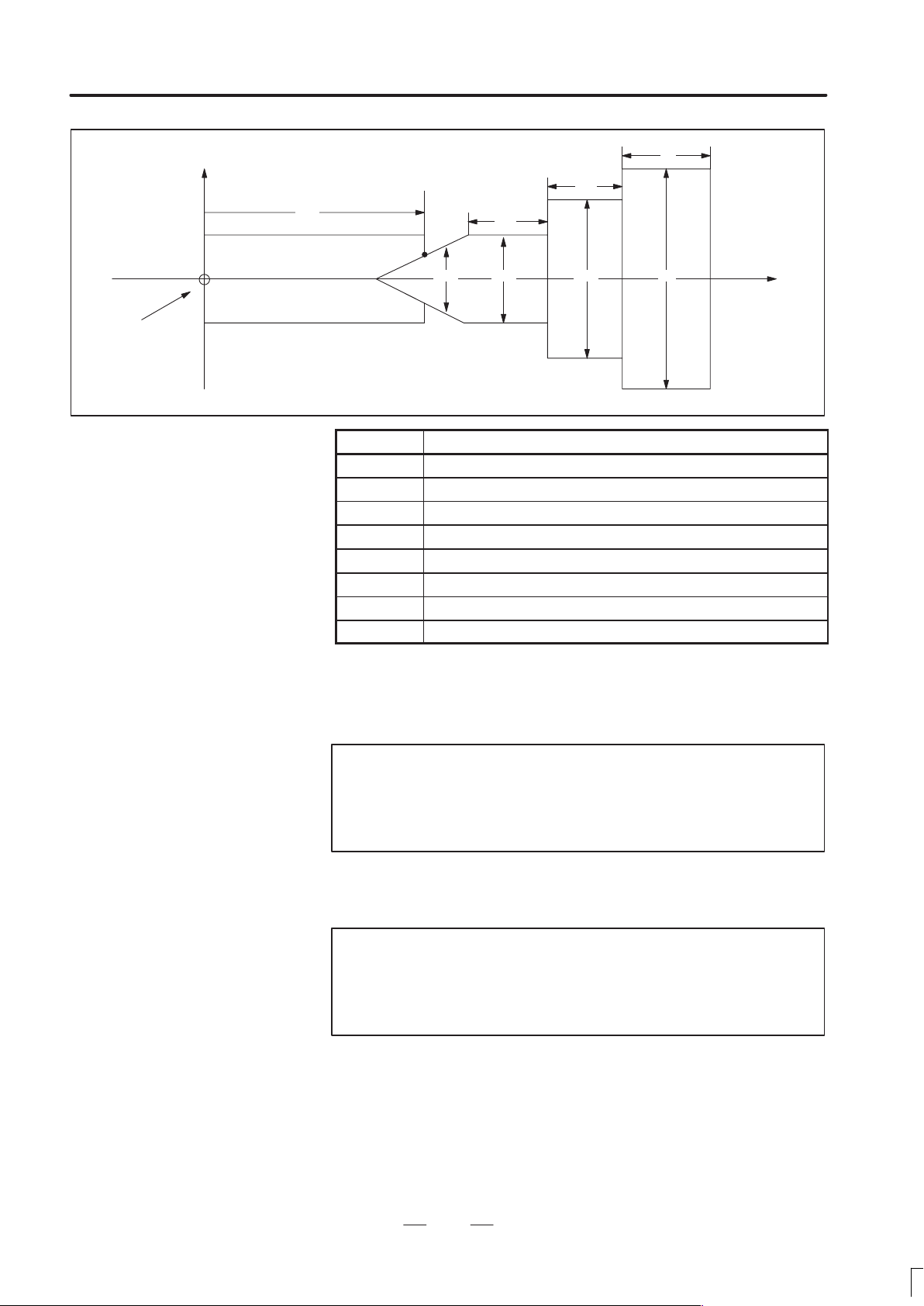
B–62760EN/01
4. DESCRIPTION OF P ARAMETERS
Zero point of
the workpiece
coordinate
system
X
Workpiece
TZ
L
L1
L2
B
D3
Symbol Description
TZ Z–axis coordinate of a tailstock
L Length of a tailstock
D Diameter of a tailstock (diameter input)
L1 Length of a tailstock (1)
D1 Diameter of a tailstock (1) (diameter input)
L2 Length of a tailstock (2)
D2 Diameter of a tailstock (2) (diameter input)
D3 Diameter of the hole of a tailstock (diameter input)
D2 D1 D
Z
TZ: Specifies the position (point B) of a tailstock with the Z–axis coordinate
of the workpiece coordinate system. In this case, do not use the coordinate
of the machine coordinate system. The profile of a tailstock is assumed to
be symmetrical with respect to the Z–axis.
Note
Specifying the position of a tailstock with a radius or
diameter depends on whether the Z–axis conforms to
radius or diameter specification.
L, L1, L2, D, D1, D2, and D3:
Define the profile of a tailstock.
Note
Always specify D, D1, D2, and D3 with diameters. Specify
L, L1, and L2 with radiuses if the Z–axis conforms to
radius specification.
59
Page 66

4. DESCRIPTION OF P ARAMETERS
4.7
PARAMETERS OF
FEEDRATE
B–62760EN/01
#7
1401
#6
RDR
RDR
#5
TDR
TDR
#4
RFO
RFO
#3 #2
JZR
#1
LRP
LRP
[Data type] Bit
RPD Manual rapid traverse during the period from power–on time to the
completion of the reference position return.
0: Disabled (Jog feed is performed.)
1: Enabled
LRP Positioning (G00)
0: Positioning is performed with non–linear type positioning so that the
tool moves along each axis independently at rapid traverse.
1: Positioning is performed with linear interpolation so that the tool
moves in a straight line.
JZR The manual reference position return at JOG feedrate
0: Not performed
1: Performed
RFO When cutting feedrate override is 0% during rapid traverse,
0: The machine tool does not stop moving.
1: The machine tool stops moving.
#0
RPD
RPD
TDR Dry run during threading or tapping (tapping cycle G74 or G84, rigid
tapping)
0: Enabled
1: Disabled
RDR Dry run for rapid traverse command
0: Disabled
1: Enabled
#7
1402
#6 #5 #4
JRV
#3
OV2
OV2
#2 #1 #0
[Data type] Bit
NPC The feed per rotation command is:
0: Ineffective when a position coder is not provided.
1: Effective even when a position coder is not provided (because the
CNC converts it to the feed per minute command automatically).
OV2 2nd feedrate override is
0: specified every 1%
1: specified every 0.01%
NPC
NPC
60
Page 67

B–62760EN/01
4. DESCRIPTION OF P ARAMETERS
Note
Signals used for 2nd feedrate override are:
*AFV0 to AFV7 (G013) when OV2 = 0
*APF00 to *AFP15 (G094, G095) when OV2 = 1
JRV Manual continuous feed (jog feed)
0: Jog feed is performed at feed per minute.
1: Jog feed is performed at feed per rotation.
Note
Specify a feedrate in parameter No. 1423.
1403
#7
RTV
#6 #5 #4 #3 #2 #1 #0
Note
When this parameter is set, the power must be turned off
before operation is continued.
[Data type] Bit
MIF Cutting feedrates at feed per minute is specified by F commands
0: In units of 1 mm/min for millimeter machines or 0.01 inches/min for
inch machines.
1: In unit of 0.001 mm/min for millimeter machines or 0.00001
inches/min for inch machines.
Note
M series are not equipped with this parameter. Cutting
feedrates are specified by F commands in units of 0.001
mm/min for millimeter machines or 0.00001 inches/min for
inch machines.
MIF
RTV Override while the tool is retracting in threading
0 : Override is effective.
1 : Override is not effective.
#7
1404
#6 #5 #4 #3 #2
Note
When this parameter is set, the power must be turned off
before operation is continued.
61
F8A
F8A
#1
DLF
DLF
#0
HFC
HFC
Page 68

4. DESCRIPTION OF P ARAMETERS
[Data type] Bit
HFC The feedrate for helical interpolation is:
DLF After a reference potition is set, manual reference position return
B–62760EN/01
0: Clamped so that the feedrates along an arc and linear axis do not
exceed the maximum cutting feedrate specified by parameter.
1: Clamped so that the composite feedrate along an arc and linear axis
does not exceed the maximum cutting feedrate specified by
parameter.
performed at:
0 : Rapid traverse rate (parameter No. 1420)
1 : Manual rapid traverse rate (parameter No.1424)
Note
This parameter selects a feedrate for reference position
return performed without dogs. This parameter also
selects a feedrate when manual reference position return
is performed according to bit 7 (SJZ) of parameter No.
0002 using rapid traverse without deceleration dogs after
a reference position is set.
<For T series>
F8A Valid data range for an F command in feed–per–minute mode
<For M series>
F8A Valid data range for an F command with a decimal point in feed–per
0: Range specified with bit 0 (MIF) of parameter No. 1403
1:
Increment system Units IS–A, IS–B IS–C
Millimeter input mm/min 0.001–240000. 0.001–100000.
Inch input inch/min 0.00001–9600. 0.00001–4000.
Rotation axis deg/min 1–240000. 1–100000.
minute mode
0:
Increment system Units IS–A, IS–B IS–C
Millimeter input mm/min 0.001–99999.999.
Inch input inch/min 0.00001–999.99999.
Rotation axis (mm) deg/min 1–240000. 1–100000.
Rotation axis (inch) deg/min 1–9600. 1–4000.
1:
Increment system Units IS–A, IS–B IS–C
Millimeter input mm/min 0.001–240000. 0.001–100000.
Inch input inch/min 0.00001–9600. 0.00001–4000.
Rotation axis deg/min 1–240000. 1–100000.
62
Page 69

B–62760EN/01
Increment system
Unit of data
Increment system
Unit of data
Increment system
Unit of data
4. DESCRIPTION OF P ARAMETERS
1410 Dry run rate
[Data type] Word
[Unit of data]
[Valid data range]
Valid data range
IS-A, IS-B IS-C
Millimeter machine 1 mm/min 6 – 15000 6 – 12000
Inch machine 0.1 inch/min 6 – 6000 6 – 4800
Set the dry run rate when the manual feedrate is overridden by 100%.
Specify the jog feedrate when the override is 100% for manual linear or
circular interpolation.
1411
[Data type] Word
[Unit of data]
[Valid data range]
1414 Feedrate for retrace
[Data type] 2–word
Cutting feedrate in the automatic mode at power–on
Setting entry is acceptable.
Valid data range
IS-A, IS-B IS-C
Millimeter machine 1 mm/min 6 – 32767 6 – 32767
Inch machine 0.1 inch/min 6 – 32767 6 – 32767
When the machine requires little change in cutting feedrate during
cutting, a cutting feedrate can be specified in the parameter. This
eliminates the need to specify a cutting feedrate in the NC command data.
This parameter sets the feedrate for retrace when the retrace function is
used.
(1) For rapid traverse
[Unit of data]
[Valid data range]
Valid data range
IS-A, IS-B IS-C
Millimeter machine 1 mm/min 6 to 240000 6 to 100000
Inch machine 0.1 inch/min 6 to 96000 6 to 48000
Rotation axis 1 deg/min 6 to 240000 6 to 100000
63
Page 70

4. DESCRIPTION OF P ARAMETERS
Increment system
Unit of data
Increment system
Unit of data
Override value
1420 Rapid traverse rate for each axis
[Data type] 2–word axis
[Unit of data]
[Valid data range]
B–62760EN/01
Note
When 0 is set in this parameter, the rapid traverse rate
that is set in parameter No. 1420 is used for retrace.
(2) For cutting feed
When a value other than 0 is specified in this parameter, the same
feedrate as an F command specified using the value without a decimal
point is set and is used for retrace. When 0 is specified in this
parameter, the programmed feedrate (F command) is used for retrace.
1421 F0 rate of rapid traverse override for each axis
[Data type] Word axis
[Unit of data]
[Valid data range]
Valid data range
IS-A, IS-B IS-C
Millimeter machine 1 mm/min 30 to 240000 6 to 100000
Inch machine 0.1 inch/min 30 to 96000 6 to 48000
Rotation axis 1 deg/min 30 to 240000 6 to 100000
Set the rapid traverse rate when the rapid traverse override is 100% for
each axis.
Valid data range
IS-A, IS-B IS-C
Millimeter machine 1 mm/min 30 – 15000 30 – 12000
Inch machine 0.1 inch/min 30 – 6000 30 – 4800
Rotaion axis 1 deg/min 30 – 15000 30 – 12000
Set the F0 rate of the rapid traverse override for each axis.
Rapid traverse override signal
ROV2 ROV1
0 0 100%
0 1 50%
1 0 25%
1 1 F0
F0: Parameter 1421
64
Page 71

B–62760EN/01
Increment system
Unit of data
Increment system
Unit of data
4. DESCRIPTION OF P ARAMETERS
1442 Maximum cutting feedrate for all axes
[Data type] 2–word
[Unit of data]
[Valid data range]
Valid data range
IS-A, IS-B IS-C
Millimeter machine 1 mm/min 6 – 240000 6 – 100000
Inch machine 0.1 inch/min 6 – 96000 6 – 48000
Specify the maximum cutting feedrate.
A feedrate in the tangential direction is clamped in cutting feed so that it
does not exceed the feedrate specified in this parameter.
Note
To specify the maximum cutting feedrate for each axis,
use parameter No. 1430 instead.
1423 Feedrate in manual continuous feed (jog feed) for each axis
[Data type] Word axis
(1) In M series, or in T series when JRV, bit 4 of parameter No. 1402, is set
[Unit of data, valid range]
Millimeter machine 1 mm/min
Inch machine 0.1 inch/min
Rotaiton axis 1 deg/min
(2) When JRV, bit 4 of parameter No. 1402, is set to 1 (feed per
[Unit of data, valid range]
Increment system Unit of data Valid data range
Millimeter machine 0.01 mm/rev
Inch machine 0.001 mm/rev
Rotation axis 0.01 deg/rev
to 0 (feed per minute), specify a jog feedrate at feed per minute with an
override of 100%.
Valid data range
IS-A, IS-B IS-C
6–32767
revolution) in T series, specify a jog feedarate (feed per revolution)
under an override of 100%.
0 – 32767
65
Page 72

4. DESCRIPTION OF P ARAMETERS
Increment system
Unit of data
Increment system
Unit of data
Increment system
Unit of data
1424 Manual rapid traverse rate for each axis
[Data type] 2–word axis
[Unit of data]
[Valid data range]
B–62760EN/01
Valid data range
IS-A, IS-B IS-C
Millimeter machine 1 mm/min 30 – 30 –
Inch machine 0.1 inch/min
Rotation axis 1 deg/min
Set the rate of manual rapid traverse when the rapid traverse override is
100% for each axis.
Note
If 0 is set, the rate set in parameter 1420 is assumed.
1425 FL rate of the reference position return for each axis
[Data type] Word axis
[Unit of data]
[Valid data range]
1426 External deceleration rate of cutting feed
[Unit of data]
[Valid data range]
Valid data range
IS-A, IS-B IS-C
Millimeter machine 1 mm/min 6 – 15000 6 – 12000
Inch machine 0.1 inch/min 6 – 6000 6 – 4800
Rotaion axis 1 deg/min 6 – 15000 6 – 12000
Set feedrate (FL rate) after deceleration when the reference position return
is performed for each axis.
Valid data range
IS-A, IS-B IS-C
Millimeter machine 1 mm/min 6 – 15000 6 – 12000
Inch machine 0.1 inch/min 6 – 6000 6 – 4800
Set the external deceleration rate of cutting feed.
66
Page 73
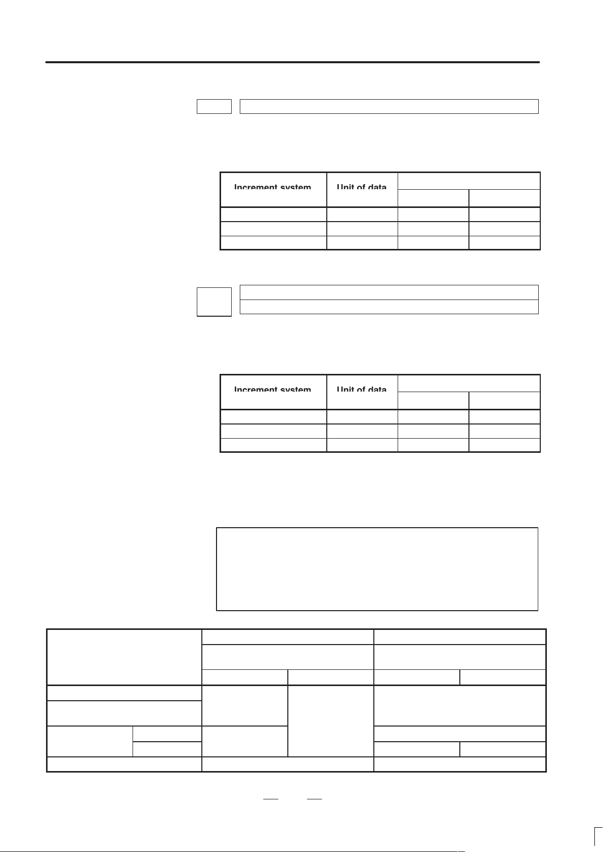
B–62760EN/01
Increment system
Unit of data
Increment system
Unit of data
iti
No.1424
4. DESCRIPTION OF P ARAMETERS
1427 External deceleration rate of rapid traverse for each axis
[Data type] Word axis
[Unit of data]
[Valid data range]
Valid data range
IS-A, IS-B IS-C
Millimeter machine 1 mm/min 6 – 15000 6 – 12000
Inch machine 0.1 inch/min 6 – 6000 6 – 4800
Rotaion axis 1 deg/min 6 – 15000 6 – 12000
Set the external deceleration rate of rapid traverse for each axis.
1428
[Data type] 2–word axis
[Unit of data]
[Valid data range]
Reference position return feedrate
Valid data range
IS-A, IS-B IS-C
Millimeter machine 1 mm/min 30 – 240000 6 – 100000
Inch machine 0.1 inch/min 30 – 96000 6 – 48000
Rotaion axis 1 deg/min 30 – 240000 6 – 100000
This parameter sets a rapid traverse rate for reference position return
operation using deceleration dogs, or for reference position return
operation before a reference position is set.
This parameter is also used to set a feedrate for the rapid traverse
command (G00) in automatic operation before a reference position is set.
Note
This parameter is enabled when the reference position
return feedrate setting function is used. When 0 is set in
this parameter, this parameter disables the reference
position return feedrate setting function.
Reference position return by G28
Raped traverse command (G00) in
automatic operation
Manual reference
pos
on return
Manual raped traverse No.1423 or No.1424
Without dogs
With dogs
*1
Before a reference position is set After a reference position is set
Reference position ruturn feedrate set-
ting function
Disabled Enabled Disabled Enabled
No.1420
No.1428
*1
67
Reference position return feedrate set-
No.1424 No.1428
*2
ting function
No.1420
No.1420 or No.1424
No.1424
*3
Page 74

4. DESCRIPTION OF P ARAMETERS
Increment system
Unit of data
Increment system
Unit of data
*1 With/without dogs: Reference position return operation not using/using
*2 For manual rapid traverse before a reference position is set, a jog feedrate
*3 The raped traverse rate set in parameter No. 1424 or No.1420 is used
B–62760EN/01
deceleration dogs
(parameter No. 1423) or manual raped traverse rate (parameter No. 1424)
is used according to the setting of bit 0 (RPD) of parameter No. 1401.
according to the setting of bit 1 (DLF) of parameter No.1404 when
reference position return is perfomed without dogs, or when reference
position return operation is performed with bit 7 (SJZ) of parameter No.
0002 set to 1 after a reference position is set (when reference position
return operation is performed using rapid traverse without deceleration
dogs).
1430
[Data type] 2–word axis
Millimeter machine 1 mm/min 6 – 240000 6 – 100000
Inch machine 0.1 inch/min 6 – 96000 6 – 48000
Rotaion axis 1 deg/min 6 – 240000 6 – 100000
Specify the maximum cutting feedrate for each axis.
A feedrate for each axis is clamped in cutting feed so that it does not
exceed the maximum feedrate specified for each axis.
Notes
1 This parameter is effective only in linear and circular
interpolation. In polar coordinate, cylindrical, and involute
interpolation, the maximum feedrate for all axes specified
in parameter No. 1422 is effective.
2 If the setting for each axis is 0, the maximum feedrate
specified in parameter No. 1422 is applied to all axes and
the feedrate is clamped at the maximum feedrate.
Maximum cutting feedrate for each axis
Valid data range
IS-A, IS-B IS-C
1431
[Data type] 2–words
[Unit of data, valid range]
Millimeter machine 1 mm/min 0 – 240000 0 – 100000
Inch machine 0.1 inch/min 0 – 96000 0 – 48000
Rotaion axis 1 deg/min 0 – 240000 0 – 100000
Specify the maximum cutting feedrate for all axes in the look–ahead
control mode.
Maximum cutting feedrate for all axes in the look–ahead control mode
Valid data range
IS-A, IS-B IS-C
68
Page 75

B–62760EN/01
Increment system
Unit of data
4. DESCRIPTION OF P ARAMETERS
A feedrate in the tangential direction is clamped in cutting feed so that it
does not exceed the feedrate specified in this parameter.
Notes
1 To specify the maximum cutting feedrate for each axis,
use parameter No. 1432 instead.
2 In a mode other than the look–ahead mode, the maximum
cutting feedrate specified in parameter No. 1422 or No.
1430 is applied and the feedrate is clamped at the
maximum feedrate.
1432
[Data type] 2–word axis
[Unit of data, valid range]
Millimeter machine 1 mm/min 0 – 240000 0 – 100000
Inch machine 0.1 inch/min 0 – 96000 0 – 48000
Rotaion axis 1 deg/min 0 – 240000 0 – 100000
Specify the maximum cutting feedrate for each axis in the look–ahead
control mode.
A feedrate for each axis is clamped during cutting feed so that it does not
exceed the maximum cutting feedrate specified for each axis.
Notes
1 This parameter is effective only in linear and circular
interpolation. In polar coordinate, cylindrical, and involute
interpolation, the maximum feedrate for all axes specified
in parameter No. 1431 is effective.
2 If a setting for each axis is 0, the maximum feedrate
specified in parameter No. 1431 is applied to all axes and
the feedrate is clamped at the maximum feedrate.
3 In a mode other than the look–ahead mode, the maximum
cutting feedrate specified in parameter No. 1422 or No.
1430 is applied and the feedrate is clamped at the
maximum feedrate.
Maximum cutting feedrate for each axis in the look–ahead control mode
Valid data range
IS-A, IS-B IS-C
69
Page 76

4. DESCRIPTION OF P ARAMETERS
B–62760EN/01
1450
[Data type] Byte
[Valid data range] 1 to 127
Set the constant that determines the change in feedrate as the manual pulse
generator is rotated one graduation during F1-digit feed.
∆
In the above equation, set n. That is, the number of revolutions of the
manual pulse generator, required to reach feedrate Fmaxi is obtained.
Fmaxi refers to the upper limit of the feedrate for an F1-digit feed
command, and set it in parameter 1460 or 1461.
Fmax1: Upper limit of the feedrate for F1 to F4 (parameter 1460)
Fmax2: Upper limit of the feedrate for F5 to F9 (parameter 1461)
1451
1452
Change of feedrate for one graduation on the manual pulse generator during F1
digit feed
Fmaxi
F
100n
(where, i=1 or 2)
Feedrate for F1 digit command F1
Feedrate for F1 digit command F2
1453
1454
1455
1456
1457
1458
1459
Input for setting is enabled.
[Data type] 2–word
Feedrate for F1 digit command F3
Feedrate for F1 digit command F4
Feedrate for F1 digit command F5
Feedrate for F1 digit command F6
Feedrate for F1 digit command F7
Feedrate for F1 digit command F8
Feedrate for F1 digit command F9
70
Page 77

B–62760EN/01
Increment system
Unit of data
Increment system
Unit of data
4. DESCRIPTION OF P ARAMETERS
[Unit of data]
[Valid data range]
Valid data range
IS-A, IS-B IS-C
Millimeter machine 1 mm/min 6 – 150000 6 – 120000
Inch machine 0.1 inch/min 6 – 6000 0 – 48000
Rotaion axis 1 deg/min 6 – 150000 0 – 120000
Set Feedrates for one–digit F code feed commands F1 to F9.
When an one–digit F code feed command is executed, as the feedrate is
changed by turning the manual pulse generator, these parameter values
also change accordingly.
1460
1461
[Data type] 2–word
[Unit of data]
[Valid data range]
Upper limit of feedrate for the one–digit F code command (F1 to F4)
Upper limit of feedrate for the one–digit F code command (F5 to F9)
Valid data range
IS-A, IS-B IS-C
Millimeter machine 1 mm/min 6 – 15000 6 – 12000
Inch machine 0.1 inch/min 6 – 6000 6 – 4800
Rotaion axis 1 deg/min 6 – 15000 6 – 12000
Set the upper limit of feedrate for the F1-digit feed command.
As the feedrate increases by turning the manual pulse generator, the
feedrate is clamped when it reaches the upper limit set. If an F1-digit feed
command F1 to F4 is executed, the upper limit is that set in parameter
1460. If an F1-digit command F5 to F9 is executed, the upper limit is that
set in parameter 1461.
71
Page 78

4. DESCRIPTION OF P ARAMETERS
É
É
É
É
4.8
PARAMETERS OF
ACCELERATION/
DECELERATION
CONTROL
B–62760EN/01
#7
1601
[Data type] Bit
OVB Block overlap in cutting feed
0: Blocks are not overlapped in cutting feed.
1: Blocks are overlapped in cutting feed.
Block overlap outputs the pulses remaining at the end of pulse
distribution in a block together with distribution pulses in the next block.
This eliminates changes in feedrates between blocks.
Block overlap is enabled when blocks containing G01, G02, or G03 are
consecutively specified in G64 mode. If minute blocks, however, are
specified consecutively, overlap may not be performed.
The following pulses in block F2 are added to the pulses remaining at the
end of pulse distribution in block F1.
(Number of pulses to be added) = F2
When F1 = F2
#6
ACD
ACD
#5
NCI
NCI
#4
RTO
RTO
#3 #2
OVB
#1 #0
(Number of pulses required at the end of block F1)
F1
F
F1 F2
t
When block overlap is disabled
72
Page 79

B–62760EN/01
É
É
É
4. DESCRIPTION OF P ARAMETERS
F
F1 F2
t
When block overlap is enabled
RTO Block overlap in rapid traverse
0 : Blocks are not overlapped in rapid traverse.
1 : Blocks are overlapped in rapid traverse.
Note
See the description of parameter No. 1722.
NCI Inposition check at deceleration
0 : Performed
1 : Not performed
ACD Function for automatically reducing the feedrate at corners (automatic
corner override function)
0 : The function is not used.
1 : The function is used.
#7
1602
#6
LS2
#5 #4
CSD
#3 #2 #1 #0
[Data type] Bit
FWB Cutting feed acceleration/deceleration before interpolation
0 : Type A of acceleration/deceleration before interpolation is used.
1 : Type B of acceleration/deceleration before interpolation is used.
Type A: When a feedrate is to be changed by a command,
acceleration/deceleration starts after the program enters the
block in which the command is specified.
Type B: When a feedrate is to be changed by a command, deceleration
starts and terminates at the block before the blcock in which the
command is specified.
When a feedrate is to be changed by a command, acceleration
starts after the program enters theblock in which the command
is specified.
FWB
73
Page 80

4. DESCRIPTION OF P ARAMETERS
<Example of a deceleration process> <Example of a acceleration process>
B–62760EN/01
Specified feedrate
Feedrate
Point 1
F3
F2
F1
Type B
N1 N2
To change the feedrate from F3 to F2, it is necessary to start reducing the feedrate at point 1.
Feedrate after acceleration/
deceleration before interpolation is applied
Type A
Time
Feedrate
F3
F2
F1
N1 N2
Specified feedrate
Feedrate after acceleration/
deceleration before interpolation is applied
CSD In the function for automatically reducing a feedrate at corners,
0 : Angles are used for controlling the feedrate.
1 : Differences in feedrates are used for controlling the feedrate.
Time
LS2 Acceleration/deceleration after interpolation for cutting feed in the
look–ahead control mode is:
0 : Exponential acceleration/deceleration
1 : Linear acceleration/deceleration. (The function for linear
acceleration/deceleration after interpolation for cutting feed is
required.)
#7
1610
#6 #5 #4
JGLx
#3 #2 #1
[Data type] Bit axis
CTLx Acceleration/deceleration in cutting feed including feed in dry run
0 : Exponential acceleration/deceleration is applied.
1 : Linear acceleration/deceleration after interpolation is applied.
Note
If the optional function of linear acceleration/deceleration
after interpolation in cutting feed is not provided,
exponential acceleration/deceleration is used irrespective
of this setting.
CTBx#0CTLx
74
Page 81

B–62760EN/01
Acceleration/deceleration
4. DESCRIPTION OF P ARAMETERS
To use bell–shaped acceleration/deceleration after interpolation, set this
parameter to 0 and select the acceleration/deceleration using CTBx, bit 1
of parameter No. 1610.
Parameter
CTBx CTLx
0 0
0 1
1 0
Exponential acceleration/deceleration
Linear acceleration/deceleration after
interpolation
Bell–shaped acceleration/decelera-
tion after interpolation
CTBx Acceleration/deceleration in cutting feed including feed in dry run
0 : Exponential acceleration/deceleration or linear acceleration/decel-
eration after interpolation is applied (depending on the setting in
CTLx, bit 0 of parameter No. 1610).
1 : Bell–shaped acceleration/deceleration after interpolation is applied.
Note
This parameter is effective only when the function of
bell–shaped acceleration/deceleration after interpolation
in cutting feed is provided. If the function is not provided,
the setting in CTLx, bit 0 of parameter No. 1610,
determines the type of acceleration/deceleration
irrespective of the setting in this parameter.
JGLx Acceleration/deceleration in jog feed
0 : Exponential acceleration/deceleration is applied.
1 : Linear acceleration/deceleration after interpolation or bell–shaped
acceleration/deceleration after interpolation is applied (depending on
which is used for cutting feed).
1620
Time constant used for linear acceleration/deceleration or bell–shaped acceleration/deceleration in rapid traverse for each axis
[Data type] Word axis
[Unit of data] ms
[Valid data range] 0 to 4000
Specify a time constant used for acceleration/deceleration in rapid traverse. When the optional function of bell–shaped acceleration/deceleration in rapid traverse is provided, bell–shaped acceleration/deceleration is
applied in rapid traverse. If the function is not provided, linear acceleration/deceleration is applied.
(1) When the function is provided, set this parameter to time constant T1
used in bell–shaped acceleration/deceleration in rapid traverse, and
set parameter No. 1621 to time constant T2.
(2) When the function is not provided, specify a time constant used in
linear acceleration/deceleration.
75
Page 82
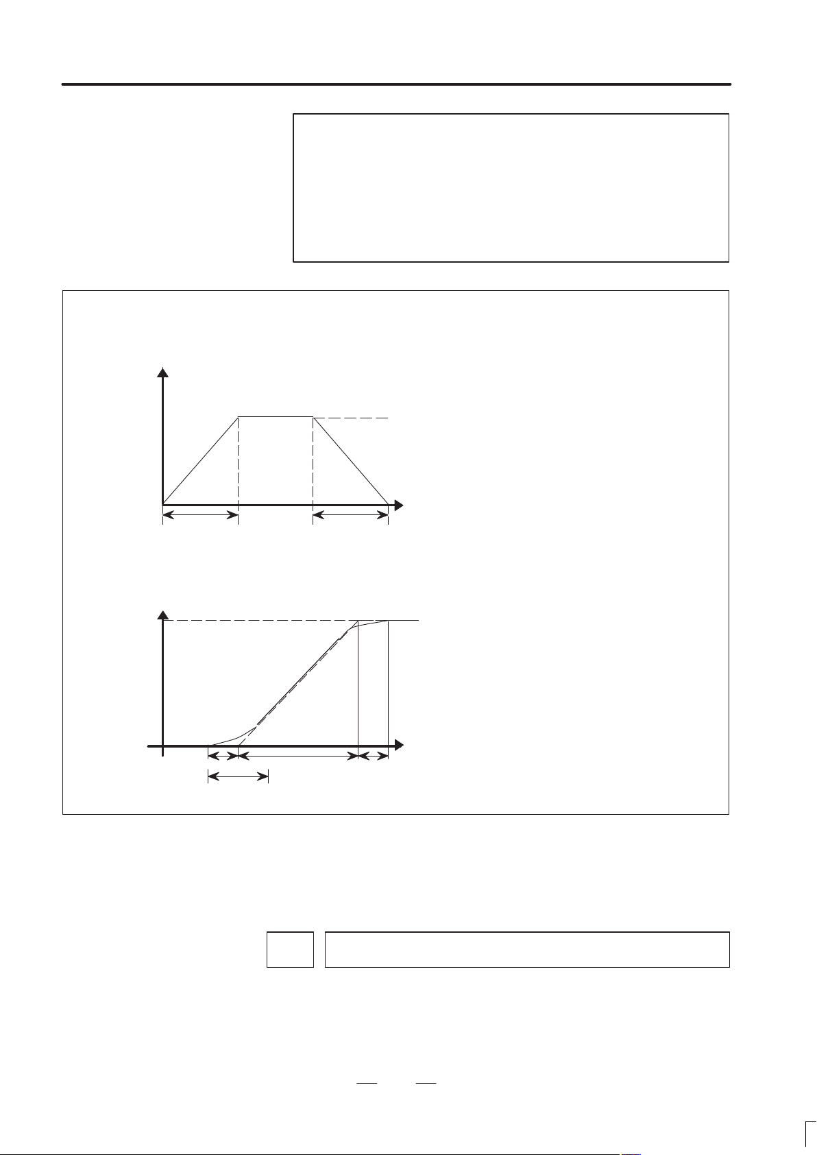
4. DESCRIPTION OF P ARAMETERS
<Rapid traverese linear acceleration/deceleration>
Speed
B–62760EN/01
Note
When parameter No. 1621 (time constant T2 used for
bell–shaped acceleration/deceleration in rapid traverse) is
set to 0, linear acceleration/deceleration is applied in rapid
traverse even if the function is provided. In this case, this
parameter stands for a time constant used in linear
acceleration/deceleration in rapid traverse.
Rapid traverse feed rate
T
<Rapid traverse bell shaped acceleration/deceleration>
Speed
Rapid
traverse rate
T2/2
T
2
T
1
T
Set the value when the rapid traverse rate is 100%. If it is under 100%, the
total time is reduced. (Constant acceleration method)
The value of T1 is determined from the torque of motor. Usually set the
value of T2 to 24 ms ir 32 ms.
T2/2
Time
TIme
T: Time constant for linear
acceleration/deceleration
T1: Set a time constant used for lin-
ear acceleration/deceleration
: Set a time for rounding.
T
2
Total time=T1 + T
Time for linear=T1 – T
Time for rounding part=T
2
2
2
1621
[Data type] Word axis
[Unit of data] ms
[Valid data range] 0 to 512
Time constant t T2 used for bell–shaped acceleration/deceleration in rapid traverse for each axis
76
Page 83

B–62760EN/01
4. DESCRIPTION OF P ARAMETERS
Specify time constant T2 used for bell–shaped acceleration/deceleration
in rapid traverse for each axis.
Notes
1 This parameter is effective when the function of
bell–shaped acceleration/deceleration in rapid traverse is
provided. Set parameter No. 1620 to time constant T1
used for bell–shaped acceleration/deceleration in rapid
traverse, and set this parameter to time constant T2.
For details of time constants T1 and T2, see the
description of parameter No.1620.
2 When this parameter is set to 0, linear
acceleration/deceleration is applied in rapid traverse. The
setting in parameter No. 1620 is used as a time constant
in linear acceleration/deceleration.
1622
Time constant of exponential acceleration/deceleration or bell–shaped acceleration/deceleration after interpolation, or linear aceeleration/deceleration after
interpolation in cutting feed for each axis
[Data type] Word axis
[Unit of data] ms
[Valid data range] 0 to 4000(exponential acceleration/deceleration in cutting feed)
0 to 512 (linear or bell–shaped acceleration/deceleration after
interpolation in cutting feed)
Set the time constant used for exponential acceleration/deceleration in
cutting feed, bell–shaped acceleration/deceleration after interpolation or
linear acceleration/deceleration after interpolation in cutting feed for each
axis. Except for special applications, the same time constant must be set
for all axes in this parameter. If the time constants set for the axes dif fer
from each other, proper straight lines and arcs cannot be obtained.
Bell–shaped acceleraton/deceleration after cutting feed interpolation
Speed
T : Total time. it is constant irrespective of feed rate.
(Time constant is constant).
The curve corresponds to that T1 = T/2 and T2 = T/2 set in parameter no. 1620 and 1621.
Time
T
77
Page 84

4. DESCRIPTION OF P ARAMETERS
Increment system
Unit of data
Increment system
Unit of data
1623 FL rate of exponential acceleration/deceleration in cutting feed for each axis
[Data type] Word axis
[Unit of data]
[Valid data range]
B–62760EN/01
Valid data range
IS-A, IS-B IS-C
Millimeter machine 1 mm/min 6 – 15000 6 – 12000
Inch machine 0.1 inch/min 6 – 6000 6 – 4800
Rotaion axis 1 deg/min 6 – 15000 6 – 12000
Set the lower limit (FL rate) of exponential acceleration/deceleration in
cutting feed for each axis. Except for special applications, this parameter
must be set to 0 for all axes. If a value other than 0 is specified, proper
straight lines and arcs cannot be obtained.
Time constant of exponential acceleration/deceleration or bell–shaped accelera-
1624
tion/deceleration or linear acceleration/deceleration after interpolation, in jog
feed for each axis.
[Data type] Word axis
[Unit of data] ms
[Valid data range] 0 to 4000(exponential acceleration/deceleration in jog feed)
0 to 512 (linear or bell–shaped acceleration/deceleration after
interpolation in jog feed)
Set the time constant used for exponential acceleration/deceleration,
bell–shaped acceleration/deceleration or linear acceleration/deceleration
after interpolation in jog feed fot each axis.
1625 FL rate of exponential acceleration/deceleration in jog feed for each axis.
[Data type] Word axis
[Unit of data]
[Valid data range]
Valid data range
IS-A, IS-B IS-C
Millimeter machine 1 mm/min 6 – 15000 6 – 12000
Inch machine 0.1 inch/min 6 – 6000 6 – 4800
Rotaion axis 1 deg/min 6 – 15000 6 – 12000
Set the lower limit (FL rate) of exponential acceleration/deceleration in
cutting feed for each axis.
78
Page 85

B–62760EN/01
Increment system
Unit of data
Increment system
Unit of data
Time constant of exponetial acceleration/deceleration in the thread cutting cycle
1626
for each axis
[Data type] Word
[Unit of data] ms
[Valid data range] 0 to 4000
Set the time constant used for exponential acceleration/deceleration in the
thread cutting cycle (G76, G78 (G92 in G code system A)) for each axis.
FL rate of exponential acceleration /deceleration in the thread cutting cycle for
1627
each axis
4. DESCRIPTION OF P ARAMETERS
[Data type] Word axis
[Unit of data]
[Valid data range]
1630
[Data type] 2–word
Valid data range
IS-A, IS-B IS-C
Millimeter machine 1 mm/min 6 – 15000 6 – 12000
Inch machine 0.1 inch/min 6 – 6000 6 – 4800
Rotaion axis 1 deg/min 6 – 15000 6 – 12000
Set the lower limit (FL rate) of exponential acceleration/deceleration in
the thread cutting cycle (G76, G78 (G92 in G code system A)) for each
axis.
Parameter 1 for setting an acceleration for linear acceleration/deceleration before interpolation (maximum machining feedrate during linear acceleration/deceleration before interpolation)
Valid data range
IS-A, IS-B IS-C
Millimeter machine 1 mm/min 6 – 240000 6 – 100000
Inch machine 0.1 inch/min 6 – 96000 6 – 48000
This parameter is used to set an acceleration for linear
acceleration/deceleration before interpolation. In this parameter, set a
maximum machining speed during linear acceleration/deceleration
before interpolation. In parameter No. 1631, set a time used to reach the
maximum machining speed.
79
Page 86

4. DESCRIPTION OF P ARAMETERS
Speed
Parameter 1
B–62760EN/01
Parameter 1: Parameter No. 1630
Parameter 2: Parameter No. 1631
Time
Parameter 2
Notes
1 When 0 is set in parameter No. 1630 or parameter No.
1631, linear acceleration/deceleration before interpolation
is disabled.
2 In the look–ahead control mode, parameter No. 1770 and
parameter No. 1771 are valid.
1631
[Data type] Word
[Unit of data] 1 ms
[Valid data range]
Parameter 2 for setting an acceleration for linear acceleration/deceleration before interpolation (time used to reach the maximum machining speed during
linear acceleration/deceleration before interpolation.)
0 to 4000
This parameter is used to set an acceleration for linear
acceleration/deceleration before interpolation. In this parameter, set the
time (time constant) used to reach the speed set in parameter No. 1630.
Notes
1 When 0 is set in parameter No. 1630 or parameter No.
1631, linear acceleration/deceleration before interpolation
is disabled.
2 In parameter Nos. 1630 and 1631, set values that satisfy
the following:
Parameter No. 1630/Parameter No. 1631 > 5
3 In the look–ahead control mode, parameter No. 1770 and
parameter No. 1771 are valid.
80
Page 87
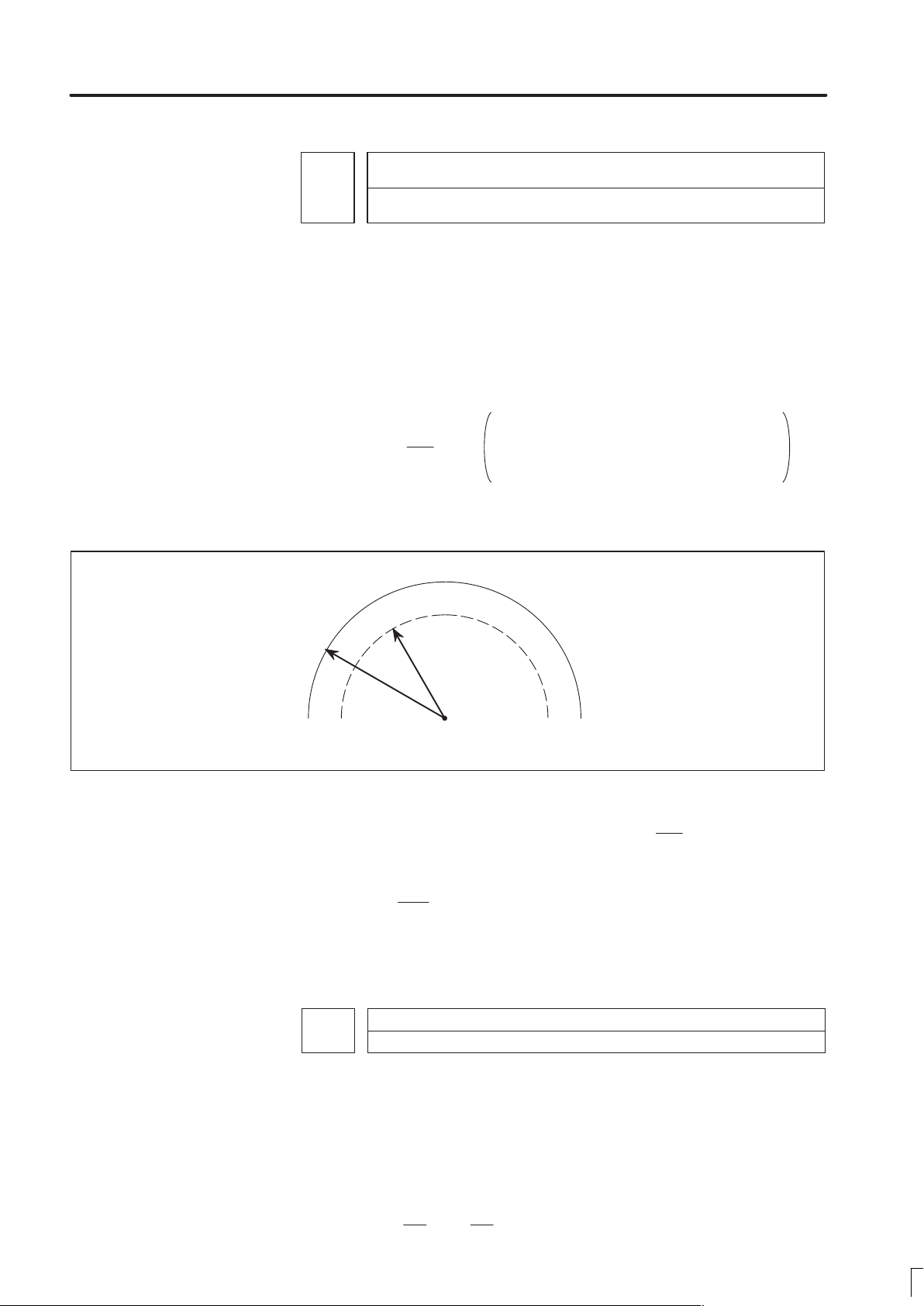
B–62760EN/01
4. DESCRIPTION OF P ARAMETERS
1710
[Data type] Byte
[Unit of data] %
[Valid data range]
Minimum deceleration ratio (MDR) of the inner circular cutting rate in automatic
corner override
1 to 100
Set the minimum deceleration ratio (MDR) in changing the inner circular
cutting feed rate by automatic corner override.
In circular cutting with an inward offset, the actual feedrate for a specified
feedrate (F) becomes as follows:
Rc
Rp
F
Rc: Radius of the path of the cutter’s center
Rp: Programmed radius
By the actual feedrate becomes the value obtained from the above
equation, the specified rate F can be achieved on the program path.
If Rc is too small in comparison with Rp so that
stop. To prevent this, the minimum deceleration ratio (MDR) is set.
When
The actual rate becomes as follows:
F (MDR)
1711
[Data type] Byte
[Unit of data] Degree
Rc
Cutter center
Rp
Fig. 4.8 (a) Rp and Rc
path
Rc
.
=
0,
.
Rp
Angle (θp) to recognize the inner corner in automatic override
Programmed path
Rc
8 0, the cutter will
Rp
[Valid data range]
1 to 179 (standard value = 91)
Set the angle to recognize the inner corner when automatic override is
performed for the inner corner.
81
Page 88
4. DESCRIPTION OF P ARAMETERS
B–62760EN/01
1712
[Data type] Byte
[Unit of data] %
[Valid data range]
1 to 100 (standard value = 50)
Set the amount of automatic override for an inner corner.
1713
[Data type] Word
[Unit of data]
Increment system IS–A IS–B IS–C Unit
Input in mm 1 0.1 0.01
Input in inches 0.1 0.01 0.001
[Valid data range] 0 to 3999
Set distance Le from the starting point in an inner comer for automatic
corner override.
Amount of automatic override for an inner corner
Distance Le from the starting point in inner corner automatic override
mm
inch
1714 Distance Ls up to the ending point in inner corner automatic override
[Data type] Word
[Unit of data]
Increment system IS–A IS–B IS–C Unit
Input in mm
Input in inches inch
[Valid data range] 0 to 3999
Set distance Ls up to the end point in an inner corner for automatic corner
override.
Ifx p, the inside of a comer is recognized. ( is set in parameter 1711.)
When an inner corner is recognized, the feedrate is overridden in the range
of Le in the block immediately before the intersection of the corner and Ls
in the next block following the intersection.
Ls and Le are each a straight line connecting the intersection of the corner
and a given point on the path of the cutter’s center.
mm
82
Page 89

B–62760EN/01
4. DESCRIPTION OF P ARAMETERS
Ls and Le are set in parameters 1713 and 1714.
Examples
Fig.4.8 (c) Distance Le and Ls in the automatic corner override at
1722 Rapid traverse feedrate reduction ratio for overlapping rapid traverse blocks
[Data type] Byte axis
[Unit of data] %
[Valid data range] 1 to 100
This parameter is used when rapid traverse blocks are arranged
successively, or when a rapid traverse block is followed by a block that
does not cause, movement. When the feedrate for each axis of a block is
reduced to the ratio set in this parameter, the execution of the next block is
started.
Le
θ
a
An override is applied from point a to b.
an inner corner
Ls
b
Programmed
path
Cutter center
path
X–axis feedrate
N1 G00 X– – ; N2 G00 X– – ;
Fh
Fh
: Rapid traverse feedrate
a
: Setting of parameter No. 1722 (feedrate reduction ratio)
Fd
: Feedrate where deceleration is terminated: Fh x a/100
When the function of overlapping rapid
traverse blocks is enabled
When the function of overlapping rapid
Fd
traverse blocks is disabled
t
Note
The parameter No. 1722 is effective when parameter No.
1601 #4 (RT0) is set to 1.
83
Page 90

4. DESCRIPTION OF P ARAMETERS
Increment system
Unit of data
Increment system
Unit of data
1730 Maximum feedrate for arc radius R
[Data type] Word
[Unit of data]
1731 Arc radius value corresponding to a maximum feedrate
[Data type] 2–word
[Unit of data]
B–62760EN/01
Valid data range
IS-A, IS-B IS-C
Millimeter machine 1 mm/min 8 – 15000 0 – 12000
Inch machine 0.1 inch/min 8 – 6000 0 – 4800
Set a maximum feedrate for the arc radius set in parameter No. 1731. Set
this parameter when the arc radius–based feedrate clamping function is
enabled.
Unit IS–A IS–B IS–C Unit
Linear axis
(millimeter machine)
Linear axis
(inch machine)
[Valid data range] 1000 to 99999999
Set the arc radius corresponding to the maximum feedrate set in parameter
No. 1730. Set this parameter when the arc radius–based feedrate clamping
function is enabled.
1732 Minimum value (RV min) for arc radius–based feedrate clamp
[Data type] Word
Millimeter machine 1 mm/min 0 – 15000 0 – 12000
Inch machine 0.1 inch/min 0 – 6000 0 – 4800
The arc radius–based feedrate clamping function reduces the maximum
feedrate as the arc radius decreases. When the specified maximum
feedrate is not greater than R V min (minimum value for arc radius–based
feedrate clamping), RV min is used as the maximum feedrate.
0.01 0.001 0.0001 mm
0.001 0.0001 0.00001 inch
Valid data range
IS-A, IS-B IS-C
1740 Critical angle subtended by two blocks for automatic corner deceleration
[Data type] 2–word
[Unit of data] 0.001 deg
[Valid data range] 0 to 180000
Set a critical angle to be subtended by two blocks for corner deceleration
when the angle–based automatic corner deceleration function is used.
84
Page 91

B–62760EN/01
Increment system
Unit of data
Increment system
Unit of data
4. DESCRIPTION OF P ARAMETERS
The angle subtended by two blocks is defined as in the examples shown
below .
Block A (G01)
θ
Block B (G01)
Angle subtended by two straight lines
1741
[Data type] Word axis
[Unit of data]
Millimeter machine 1 mm/min 6 – 15000 6 – 12000
Inch machine 0.1 inch/min 6 – 6000 6 – 4800
Rotaion axis 1 deg/min 6 – 15000 6 – 12000
Set the feedrate for assuming the termination of deceleration in automatic
corner deceleration.
θ
Block A (G02)
Block B(G01)
Angle subtended by an arc and its tangent
Feedrate for assuming the termination of automatic corner deceleration (for acceleration/deceleration after interpolation)
Valid data range
IS-A, IS-B IS-C
1762
Exponential acceleration/deceleration time constant for cutting feed in the look–
ahead control mode
[Data type] Word axis
[Unit of data] 1 ms
[Valid data range] 0 to 4000
Set an exponential acceleration/deceleration time constant for cutting
feed in the look–ahead control mode.
1763
Minimum speed in exponential acceleration/deceleration for cutting feed in the
look–ahead control mode
[Data type] Word axis
Millimeter machine 1 mm/min 6 – 15000 6 – 12000
Inch machine 0.1 inch/min 6 – 6000 6 – 4800
Rotation axis 1 deg/min 6 – 15000 6 – 12000
Set minimum speed (FL) in exponential acceleration/deceleration for
cutting feed in the look–ahead control mode.
Valid data range
IS-A, IS-B IS-C
85
Page 92

4. DESCRIPTION OF P ARAMETERS
Increment system
Unit of data
B–62760EN/01
1768
[Data type] Word axis
[Unit of data] ms
[Valid data range] 8 to 512
This parameter sets a time constant for linear acceleration/deceleration for
cutting feed in the look–ahead control mode.
Note
The function for linear acceleration/deceleration after
interpolation for cutting feed isrequired.
1770
[Data type] 2–word
[Unit of data, valid range]
Time constant for linear acceleration/deceleration during cutting feed in lock–
ahead control mode.
Parameter 1 (for look–ahead control) for setting an acceleration for linear acceleration/deceleration before interpolation (maximum machining speed during linear
acceleration/deceleration before interpolation)
Millimeter machine 1 mm/min 6 – 240000 6 – 100000
Inch machine 0.1 inch/min 6 – 96000 6 – 48000
This parameter is used to set an acceleration for linear
acceleration/deceleration before interpolation in the look–ahead control
mode. In this parameter, set the maximum machining speed during linear
acceleration/deceleration before interpolation. Set the time used to reach
the maximummachining speed in parameter No.1771.
Parameter 1
(No. 1770)
Valid data range
IS-A, IS-B IS-C
Speed
Time
Parameter 2 (No. 1771)
Note
When 0 is set in parameter No. 1770 or parameter No.
1771, linear acceleration/deceleration before interpolation
is disabled.
86
Page 93

B–62760EN/01
Increment system
Unit of data
Increment system
Unit of data
1771
[Data type] Word
[Unit of data] 1 msec
[Valid range] 0 to 4000
This parameter is used to set an acceleration for linear
acceleration/deceleration before interpolation in the look–ahead control
mode. In this parameter, set the time (time constant) used toreach the
speed set in parameter No. 1770.
Notes
1 When 0 is set in parameter No. 1770 or parameter No.
1771, linear acceleration/deceleration before interpolation
is disabled.
2 In parameter Nos. 1770 and 1771, set values that satisfy
the following:
Parameter No. 1770/Parameter No. 1771 y 5
4. DESCRIPTION OF P ARAMETERS
Parameter 2 (for look–ahead control) for setting an acceleration for linear acceleration/deceleration before interpolation (time used to reach the maximum machining speed during linear acceleration/deceleration before interpolation)
1775 (Must not be used)
1776 (Must not be used)
1777 Minimum speed for the automatic corner deceleration function (look–ahead control)
[Data type] Word axis
[Unit of data, valid range]
Millimeter machine 1 mm/min 6 – 15000 6 – 12000
Inch machine 0.1 inch/min 6 – 6000 6 – 4800
Rotation axis 1 deg/min 6 – 15000 6 – 12000
Set a speed at which the number of buffered pulses in deceleration is
assumed to be 0 when linear acceleration/deceleration before
interpolation is used.
1778
[Data type] Word axis
[Unit of data, valid range]
Valid data range
IS-A, IS-B IS-C
Minimum speed of for the automtic corner deceleration function (for linear acceleration/deceleration before interpolation)
Valid data range
IS-A, IS-B IS-C
Millimeter machine 1 mm/min 6 – 15000 6 – 12000
Inch machine 0.1 inch/min 6 – 6000 6 – 4800
Rotation axis 1 deg/min 6 – 15000 6 – 12000
87
Page 94

4. DESCRIPTION OF P ARAMETERS
Increment system
Unit of data
Increment system
Unit of data
B–62760EN/01
Set a speed at which the number of buffered pulses in deceleration is
assumed to be 0 when linear acceleration/deceleration before
interpolation is used.
1779
Critical angle subtended by two blocks for automatic corner deceleration (for
look–ahead control)
[Data type] 2–word
[Unit of data] 0.001 deg
[Valid data range] 0 to 180000
Set a critical angle to be subtended by two blocks for corner deceleration
when the angle–basedautomatic corner deceleration function is used.
The angle subtended by two blocks is defined as θ in the examples shown
below .
Block A (G01)
θ
Angle subtended by two straight lines
Block B (G01)
θ
Block A (G02)
Block B (G01)
Angle subtended by an arc and its tangent
1780
[Data type] Word
[Unit of data, valid range]
Millimeter machine 1 mm/min 6 – 15000 6 – 12000
Inch machine 0.1 inch/min 6 – 6000 6 – 4800
Set the speed difference for the speed difference–based automatic corner
deceleration function when linear acceleration/deceleration before
interpolation is used.
[Data type] Word axis
[Unit of data, valid range]
Millimeter machine 1 mm/min 6 – 15000 6 – 12000
Inch machine 0.1 inch/min 6 – 6000 6 – 4800
Rotation axis 0.1 deg/min 6 – 15000 6 – 12000
Allowable speed difference for the speed difference–based corner deceleration
function (for linear acceleration/deceleration before interpolation)
Valid range
IS-A, IS-B IS-C
Valid range
IS-A, IS-B IS-C
88
Page 95

B–62760EN/01
Increment system
Unit of data
Increment system
Unit of data
4. DESCRIPTION OF P ARAMETERS
1781
Set speed difference for the speed difference–based automatic corner
deceleration function when linear acceleration/deceleration after
interpolation used.
1783
[Data type] Word axis
[Unit of data, valid range]
Millimeter machine 1 mm/min 6 – 15000 6 – 12000
Inch machine 0.1 inch/min 6 – 6000 6 – 4800
Rotation axis 0.1 deg/min 6 – 15000 6 – 12000
A separate allowable feedrate difference can be set for each axis. The
allowable feedrate difference is set for each axis with this parameter.
Among the axes that exeed the specified allowable feedrate difference, the
axis with the greatest ratio of the actual feedrate difference to the
allowable feedrate difference is used as the reference to calculate the
reduced feedrate at the corner.
Allowable speed difference for the speed difference–based corner deceleration
function (linear acceleration/deceleration after interpolation)
Allowable speed difference for the speed difference based corner deceleration
function (linear acceleration/deceleration before interpolation)
Valid range
IS-A, IS-B IS-C
1784
[Data type] Word axis
[Unit of data]
[Valid data range]
Speed when overtravel alarm has generated during acceleration/deceleration
before interpolation
Valid range
IS-A, IS-B IS-C
Millimeter machine 1 mm/min 6 – 15000 6 – 12000
Inch machine 0.1 inch/min 6 – 6000 6 – 4800
Deceleration is started beforehand to reach the feedrate set in the
parameter when an overtravel alarm is issued (when a limit is reached)
during linear acceleration/deceleration before interpolation. By using
this parameter, the overrun distance that occurs when an overtravel alarm
is output can be reduced.
Notes
1 When 0 is set in this parameter, the control described
above is not exercised.
2 Use type–B linear acceleration/deceleration before
interpolation (by setting bit 0 (FWB) of parameter No.
1602 to 1).
3 The control described above is applicable only to stored
stroke limit 1.
89
Page 96

4. DESCRIPTION OF P ARAMETERS
4.9
PARAMETERS OF
SERVO
B–62760EN/01
#7
1800
#6 #5
TRC
#4
RBK
#3
FFR
#2
OZR#1CVR
[Data type] Bit
CVR When velocity control ready signal VRDY is set ON before position
control ready signal PRDY comes ON
0: A servo alarm is generated.
1: A servo alarm is not generated.
OZR When manual reference position return is attempted in the halt state
during automatic operation (feed hold stop state) under any of the
conditions listed below:
0: Manual reference position return is not performed, with P/S alarm No.
091.
1: Manual reference position return is performed without an alarm
occurring.
< Conditions >
(1) When there is a remaining distance to travel.
(2) When an auxiliary function (miscellaneous function, spindle–speed
function, tool function) is being executed.
(3 ) When a cycle such as a dwell cycle or canned cycle is being executed.
FFR Feed–forward control is enabled for
0 : Cutting feed only
1 : Cutting feed and rapid traverse
#0
RBK Backlash compensation applied separately for cutting feed and rapid
traverse
0: Not performed
1: Performed
TRC The servo trace functon is:
0 : Disabled
1 : Enabled (Also set parameter No. 1870.)
#7
1801
#6 #5
CIN
CIN
#4
CCI
CCI
#3 #2 #1
PM2
#0
PM1
[Data type] Bit
PM1, PM2 Sets a gear ratio between the spindle and motor when the servo
motor–based speed control function is used.
Magnification PM2
1/1
1/2
1/4
1/8
0
0
1
1
PM1
0
1
0
1
Magnification=
spindle speed
motor speed
90
Page 97

B–62760EN/01
4. DESCRIPTION OF P ARAMETERS
CCI The in–position area for cutting feed is:
0 : Set in parameter No. 1826 (same as for rapid traverse).
1 : Set in bit 5 (CIN) of parameter No. 1801.
CIN When bit 4 (CCI) of parameter No. 1801 = 1, the in–position area for
cutting feed is:
0 : Use value in parameter No. 1827 if the next block is also for cutting
feed, or use value in parameter No. 1826 if the next block is not for
cutting feed.
1 : Use value in parameter No. 1827, regardless of the next block. (The
setting of parameter No. 1826 is used for rapid traverse, and the
setting of parameter No. 1827 is used for cutting feed.)
#7
1802
#6 #5
DPS
#4 #3 #2 #1 #0
Note
After this parameter is set, the power needs to be turned
off.
[Data type] Bit
CTS The servo motor–based speed control function is:
0 : Not used
1 : Used
DPS When servo motor–based speed control is applied, a position coder is:
0 : Used
1 : Not used
#7
1804
#6
SAK
#5 #4 #3 #2 #1 #0
[Data type] Bit axis
CTS
SAK When the VRDY OFF alarm ignore signal IGNVRY is 1, or when the
VRDY OFF alarm ignore signals IGVRY1 to IGVRY8 are 1:
0 : Servo ready signal SA is set to 0.
1 : Servo ready signal SA remains set to 1.
#7
ZMGx1815
#6 #5
APCx#4APZx
#3 #2 #1
OPTx
Note
When this parameter has been set, the power must be
turned off before operation is continued.
[Data type] Bit axis
OPTx Position detector
91
#0
Page 98

4. DESCRIPTION OF P ARAMETERS
Detection multiply
APZx Machine position and position on absolute position detector when the
APCx Position detector
B–62760EN/01
0 : A separate pulse coder is not used.
1 : A separate pulse coder is used.
absolute position detector is used
0 : Not corresponding
1 : Corresponding
Note
When an absolute position detector is used, after primary
adjustment is performed or after the absolute position
detector is replaced, this parameter must be set to 0,
power must be turned off and on, then manual reference
position return must be performed. This completes the
positional correspondence between the machine position
and the position on the absolute position detector, and
sets this parameter to 1 automatically.
0 : Other than absolute position detector
1 : Absolute position detector (absolute pulse coder)
ZMGx Reference position return method is:
0 : Grid method
1 : Magne–switch method
#7
1816
#6
DM3x#5DM2x#4DM1x
Note
When this parameter has been set, the power must be
turned off before operation is continued.
[Data type] Bit axis
DM1x to DM3x Setting of detection multiply
Set value
DM3x DM2x DM1x
0
0
0
0
1
1
1
1
0
0
1
1
0
0
1
1
#3 #2 #1 #0
0
1
0
1
0
1
0
1
1/2
1
3/2
2
5/2
3
7/2
4
Note
When the flexibly feed gear is used, do not use these
parameters. Set the numerator and denominator of DMR
to an appropriate values in parameters 2084 and 2085
respectively.
92
Page 99

B–62760EN/01
4. DESCRIPTION OF P ARAMETERS
1817
Note
When this parameter has been set, the power must be
turned off before operation is continued.
[Data type] Bit axis
TAN Tandem control
0 : Not used
1 : Used
Note
Set this parameter to both master axis and slave axis.
1819
#7
#7
#6
TAN
#6 #5 #4 #3 #2 #1 #0
#5 #4 #3 #2 #1 #0
FUPx
FUPxNAHx
[Data type] Bit axis
FUPx To perform follow–up when the servo is off is set for each axis.
0: The follow–up signal, *FLWU, determines whether follow–up is
performed or not.
When *FLWU is 0, follow–up is performed.
When *FLWU is 1, follow–up is not performed.
1: Follow–up is not performed.
Note
When the index table indexing function (M series) is used,
be sure to set FUPx of the 4th axis to 1.
NAHx In the look–ahead control mode, advanced feed–forward is:
0 : Used
1 : Not used
Note
Set1 for a PMC–based control axis.
1820 Command multiply for each axis (CMR)
Note
When this parameter has been set, the power must be
turned off before operation is continued.
93
Page 100

4. DESCRIPTION OF P ARAMETERS
[Data type] Byte axis
B–62760EN/01
Set a command multiply indicating the ratio of the least command
increment to the detection unit for each axis.
Least command increment = detection unit command multiply
Relationship between the increment system and the least command
increment
Least command increment
Increment system IS–A IS–B IS–C Unit
Millimeter machine 0.01 0.001 0.0001
Inch machine 0.001 0.0001 0.00001 inch
Rotation axis 0.01 0.001 0.0001 deg
mm
Setting command multiply (CMR), detection multiply (DMR), and the
capacity of the reference counter
least command
increment
Feedback pulse unit =
X CMR
Reference
counter
Fig.4.9 (a) CMR, DMR, and the Capacity of the Reference Counter
+
–
Detection
unit
Error counter
Feedback pulse
X DMR
DA
Converter
To velocity control
Position detector
Set the magnification ratios of CMR and DMR so that the weight of
positive inputs to the error counter equals that of negative inputs.
Least command increment
=detection unit=
feedback pulse unit
CMR
The feedback pulse unit varies according to the type of detector.
the amount of travel per rotation of the pulse coder
the number of pulses per rotation of the pulse coder (2000, 2500, or 3000)
As the size of the reference counter, specify the grid interval for the
reference position return in the grid method.
Size of the reference counter = Grid interval/detection unit
Grid interval = the amount of travel per rotation of the pulse coder
The value set in the parameter is obtained as follows:
DMR
(1) When command multiply is 1/2 to 1/27
Set value =
1
(Command multiply)
Valid data range: 102 to 127
94
+ 100
 Loading...