

Page 1

GE Fanuc Automation
Computer Numerical Control Products
Series 16 / 18 / 160 / 180 – Model C
for Machining Center
Operator's Manual
B-62764EN/01 December 1995
Page 2

Warnings, Cautions, and Notes
as Used in this Publication
Warning notices are used in this publication to emphasize that hazardous voltages, currents,
temperatures, or other conditions that could cause personal injury exist in this equipment or
may be associated with its use.
In situations where inattention could cause either personal injury or damage to equipment, a
Warning notice is used.
Caution notices are used where equipment might be damaged if care is not taken.
GFL-001
Warning
Caution
Note
Notes merely call attention to information that is especially significant to understanding and
operating the equipment.
This document is based on information available at the time of its publication. While efforts
have been made to be accurate, the information contained herein does not purport to cover all
details or variations in hardware or software, nor to provide for every possible contingency in
connection with installation, operation, or maintenance. Features may be described herein
which are not present in all hardware and software systems. GE Fanuc Automation assumes
no obligation of notice to holders of this document with respect to changes subsequently made.
GE Fanuc Automation makes no representation or warranty, expressed, implied, or statutory
with respect to, and assumes no responsibility for the accuracy, completeness, sufficiency, or
usefulness of the information contained herein. No warranties of merchantability or fitness for
purpose shall apply.
©Copyright 1995 GE Fanuc Automation North America, Inc.
All Rights Reserved.
Page 3

SAFETY PRECAUTIONS
This section describes the safety precautions related to the use of CNC units. It is essential that these precautions
be observed by users to ensure the safe operation of machines equipped with a CNC unit (all descriptions in this
section assume this configuration). Note that some precautions are related only to specific functions, and thus
may not be applicable to certain CNC units.
Users must also observe the safety precautions related to the machine, as described in the relevant manual supplied
by the machine tool builder. Before attempting to operate the machine or create a program to control the operation
of the machine, the operator must become fully familiar with the contents of this manual and relevant manual
supplied by the machine tool builder.
Contents
1. DEFINITION OF WARNING, CAUTION, AND NOTE s–2. . . . . . . . . . . . . . . . . . . . . . . .
2. GENERAL WARNINGS AND CAUTIONS s–3. . . . . . . . . . . . . . . . . . . . . . . . . . . . . . . . .
3. WARNINGS AND CAUTIONS RELATED TO PROGRAMMING s–5. . . . . . . . . . . . . .
4. WARNINGS AND CAUTIONS RELATED TO HANDLING s–7. . . . . . . . . . . . . . . . . . . .
5. WARNINGS RELATED TO DAILY MAINTENANCE s–9. . . . . . . . . . . . . . . . . . . . . . . . .
s–1
Page 4

1
SAFETY PRECAUTIONS
B–62764EN/01
DEFINITION OF WARNING, CAUTION, AND NOTE
This manual includes safety precautions for protecting the user and preventing damage to the
machine. Precautions are classified into W arning and Caution according to their bearing on safety.
Also, supplementary information is described as a Note. Read the Warning, Caution, and Note
thoroughly before attempting to use the machine.
WARNING
Applied when there is a danger of the user being injured or when there is a damage of both the user
being injured and the equipment being damaged if the approved procedure is not observed.
CAUTION
Applied when there is a danger of the equipment being damaged, if the approved procedure is not
observed.
NOTE
The Note is used to indicate supplementary information other than Warning and Caution.
Read this manual carefully, and store it in a safe place.
s–2
Page 5

B–62764EN/01
2
SAFETY PRECAUTIONS
GENERAL WARNINGS AND CAUTIONS
WARNING
1.
Never attempt to machine a workpiece without first checking the operation of the machine.
Before starting a production run, ensure that the machine is operating correctly by performing
a trial run using, for example, the single block, feedrate override, or machine lock function or
by operating the machine with neither a tool nor workpiece mounted. Failure to confirm the
correct operation of the machine may result in the machine behaving unexpectedly, possibly
causing damage to the workpiece and/or machine itself, or injury to the user.
2.
Before operating the machine, thoroughly check the entered data.
Operating the machine with incorrectly specified data may result in the machine behaving
unexpectedly , possibly causing damage to the workpiece and/or machine itself, or injury to the
user.
3.
Ensure that the specified feedrate is appropriate for the intended operation. Generally , for each
machine, there is a maximum allowable feedrate. The appropriate feedrate varies with the
intended operation. Refer to the manual provided with the machine to determine the maximum
allowable feedrate. If a machine is run at other than the correct speed, it may behave
unexpectedly , possibly causing damage to the workpiece and/or machine itself, or injury to the
user.
4.
When using a tool compensation function, thoroughly check the direction and amount of
compensation.
Operating the machine with incorrectly specified data may result in the machine behaving
unexpectedly , possibly causing damage to the workpiece and/or machine itself, or injury to the
user.
5.
The parameters for the CNC and PMC are factory–set. Usually , there is not need to change them.
When, however, there is not alternative other than to change a parameter, ensure that you fully
understand the function of the parameter before making any change.
Failure to set a parameter correctly may result in the machine behaving unexpectedly , possibly
causing damage to the workpiece and/or machine itself, or injury to the user.
6.
Immediately after switching on the power, do not touch any of the keys on the MDI panel until
the position display or alarm screen appears on the CNC unit.
Some of the keys on the MDI panel are dedicated to maintenance or other special operations.
Pressing any of these keys may place the CNC unit in other than its normal state. Starting the
machine in this state may cause it to behave unexpectedly.
7.
The operator’s manual and programming manual supplied with a CNC unit provide an overall
description of the machine’s functions, including any optional functions. Note that the optional
functions will vary from one machine model to another. Therefore, some functions described
in the manuals may not actually be available for a particular model. Check the specification of
the machine if in doubt.
s–3
Page 6

SAFETY PRECAUTIONS
B–62764EN/01
W ARNING
8.
Some functions may have been implemented at the request of the machine–tool builder. When
using such functions, refer to the manual supplied by the machine–tool builder for details of their
use and any related cautions.
NOTE
Programs, parameters, and macro variables are stored in nonvolatile memory in the CNC unit.
Usually , they are retained even if the power is turned off. Such data may be deleted inadvertently,
however, or it may prove necessary to delete all data from nonvolatile memory as part of error
recovery.
To guard against the occurrence of the above, and assure quick restoration of deleted data, backup
all vital data, and keep the backup copy in a safe place.
s–4
Page 7

B–62764EN/01
3
1.
SAFETY PRECAUTIONS
WARNINGS AND CAUTIONS RELATED TO
PROGRAMMING
This section covers the major safety precautions related to programming. Before attempting to
perform programming, read the supplied operator’s manual and programming manual carefully
such that you are fully familiar with their contents.
WARNING
Coordinate system setting
If a coordinate system is established incorrectly, the machine may behave unexpectedly as a
result of the program issuing an otherwise valid move command.
Such an unexpected operation may damage the tool, the machine itself, the workpiece, or cause
injury to the user.
2.
Positioning by nonlinear interpolation
When performing positioning by nonlinear interpolation (positioning by nonlinear movement
between the start and end points), the tool path must be carefully confirmed before performing
programming.
Positioning involves rapid traverse. If the tool collides with the workpiece, it may damage the
tool, the machine itself, the workpiece, or cause injury to the user.
3.
Function involving a rotation axis
When programming polar coordinate interpolation or normal–direction (perpendicular) control,
pay careful attention to the speed of the rotation axis. Incorrect programming may result in the
rotation axis speed becoming excessively high, such that centrifugal force causes the chuck to
lose its grip on the workpiece if the latter is not mounted securely.
Such mishap is likely to damage the tool, the machine itself, the workpiece, or cause injury to
the user.
4.
Inch/metric conversion
Switching between inch and metric inputs does not convert the measurement units of data such
as the workpiece origin offset, parameter, and current position. Before starting the machine,
therefore, determine which measurement units are being used. Attempting to perform an
operation with invalid data specified may damage the tool, the machine itself, the workpiece, or
cause injury to the user.
5.
Constant surface speed control
When an axis subject to constant surface speed control approaches the origin of the workpiece
coordinate system, the spindle speed may become excessively high. Therefore, it is necessary
to specify a maximum allowable speed. Specifying the maximum allowable speed incorrectly
may damage the tool, the machine itself, the workpiece, or cause injury to the user.
s–5
Page 8

SAFETY PRECAUTIONS
W ARNING
6.
Stroke check
After switching on the power, perform a manual reference position return as required. Stroke
check is not possible before manual reference position return is performed. Note that when stroke
check is disabled, an alarm is not issued even if a stroke limit is exceeded, possibly damaging
the tool, the machine itself, the workpiece, or causing injury to the user.
7.
Tool post interference check
A tool post interference check is performed based on the tool data specified during automatic
operation. If the tool specification does not match the tool actually being used, the interference
check cannot be made correctly, possibly damaging the tool or the machine itself, or causing
injury to the user.
After switching on the power, or after selecting a tool post manually, always start automatic
operation and specify the tool number of the tool to be used.
8.
Absolute/incremental mode
B–62764EN/01
If a program created with absolute values is run in incremental mode, or vice versa, the machine
may behave unexpectedly.
9.
Plane selection
If an incorrect plane is specified for circular interpolation, helical interpolation, or a canned cycle,
the machine may behave unexpectedly . Refer to the descriptions of the respective functions for
details.
10.
Torque limit skip
Before attempting a torque limit skip, apply the torque limit. If a torque limit skip is specified
without the torque limit actually being applied, a move command will be executed without
performing a skip.
11.
Programmable mirror image
Note that programmed operations vary considerably when a programmable mirror image is
enabled.
12.
Compensation function
If a command based on the machine coordinate system or a reference position return command
is issued in compensation function mode, compensation is temporarily canceled, resulting in the
unexpected behavior of the machine.
Before issuing any of the above commands, therefore, always cancel compensation function
mode.
s–6
Page 9

B–62764EN/01
4
1.
SAFETY PRECAUTIONS
WARNINGS AND CAUTIONS RELATED TO HANDLING
This section presents safety precautions related to the handling of machine tools. Before attempting
to operate your machine, read the supplied operator’s manual and programming manual carefully,
such that you are fully familiar with their contents.
WARNING
Manual operation
When operating the machine manually , determine the current position of the tool and workpiece,
and ensure that the movement axis, direction, and feedrate have been specified correctly.
Incorrect operation of the machine may damage the tool, the machine itself, the workpiece, or
cause injury to the operator.
2.
Manual reference position return
After switching on the power, perform manual reference position return as required. If the
machine is operated without first performing manual reference position return, it may behave
unexpectedly . Stroke check is not possible before manual reference position return is performed.
An unexpected operation of the machine may damage the tool, the machine itself, the workpiece,
or cause injury to the user.
3.
Manual numeric command
When issuing a manual numeric command, determine the current position of the tool and
workpiece, and ensure that the movement axis, direction, and command have been specified
correctly, and that the entered values are valid.
Attempting to operate the machine with an invalid command specified may damage the tool, the
machine itself, the workpiece, or cause injury to the operator.
4.
Manual handle feed
In manual handle feed, rotating the handle with a large scale factor, such as 100, applied causes
the tool and table to move rapidly. Careless handling may damage the tool and/or machine, or
cause injury to the user.
5.
Disabled override
If override is disabled (according to the specification in a macro variable) during threading, rigid
tapping, or other tapping, the speed cannot be predicted, possibly damaging the tool, the machine
itself, the workpiece, or causing injury to the operator.
6.
Origin/preset operation
Basically, never attempt an origin/preset operation when the machine is operating under the
control of a program. Otherwise, the machine may behave unexpectedly , possibly damaging the
tool, the machine itself, the tool, or causing injury to the user.
s–7
Page 10

SAFETY PRECAUTIONS
W ARNING
7.
Workpiece coordinate system shift
Manual intervention, machine lock, or mirror imaging may shift the workpiece coordinate
system. Before attempting to operate the machine under the control of a program, confirm the
coordinate system carefully.
If the machine is operated under the control of a program without making allowances for any shift
in the workpiece coordinate system, the machine may behave unexpectedly , possibly damaging
the tool, the machine itself, the workpiece, or causing injury to the operator.
8.
Software operator’s panel and menu switches
Using the software operator’s panel and menu switches, in combination with the MDI panel, it
is possible to specify operations not supported by the machine operator’s panel, such as mode
change, override value change, and jog feed commands.
Note, however, that if the MDI panel keys are operated inadvertently, the machine may behave
unexpectedly, possibly damaging the tool, the machine itself, the workpiece, or causing injury
to the user.
B–62764EN/01
9.
Manual intervention
If manual intervention is performed during programmed operation of the machine, the tool path
may vary when the machine is restarted. Before restarting the machine after manual intervention,
therefore, confirm the settings of the manual absolute switches, parameters, and
absolute/incremental command mode.
10.
Feed hold, override, and single block
The feed hold, feedrate override, and single block functions can be disabled using custom macro
system variable #3004. Be careful when operating the machine in this case.
11.
Dry run
Usually , a dry run is used to confirm the operation of the machine. During a dry run, the machine
operates at dry run speed, which differs from the corresponding programmed feedrate. Note that
the dry run speed may sometimes be higher than the programmed feed rate.
12.
Cutter and tool nose radius compensation in MDI mode
Pay careful attention to a tool path specified by a command in MDI mode, because cutter or tool
nose radius compensation is not applied. When a command is entered from the MDI to interrupt
in automatic operation in cutter or tool nose radius compensation mode, pay particular attention
to the tool path when automatic operation is subsequently resumed. Refer to the descriptions of
the corresponding functions for details.
13.
Program editing
If the machine is stopped, after which the machining program is edited (modification, insertion,
or deletion), the machine may behave unexpectedly if machining is resumed under the control
of that program. Basically , do not modify, insert, or delete commands from a machining program
while it is in use.
s–8
Page 11

B–62764EN/01
5
1.
SAFETY PRECAUTIONS
WARNINGS RELATED TO DAILY MAINTENANCE
WARNING
Memory backup battery replacement
When replacing the memory backup batteries, keep the power to the machine (CNC) turned on,
and apply an emergency stop to the machine. Because this work is performed with the power
on and the cabinet open, only those personnel who have received approved safety and
maintenance training may perform this work.
When replacing the batteries, be careful not to touch the high–voltage circuits (marked
fitted with an insulating cover).
Touching the uncovered high–voltage circuits presents an extremely dangerous electric shock
hazard.
and
NOTE
The CNC uses batteries to preserve the contents of its memory , because it must retain data such as
programs, offsets, and parameters even while external power is not applied.
If the battery voltage drops, a low battery voltage alarm is displayed on the machine operator’s panel
or CR T screen.
When a low battery voltage alarm is displayed, replace the batteries within a week. Otherwise, the
contents of the CNC’s memory will be lost.
Refer to the maintenance section of the operator’s manual or programming manual for details of the
battery replacement procedure.
s–9
Page 12

SAFETY PRECAUTIONS
B–62764EN/01
W ARNING
2.
Absolute pulse coder battery replacement
When replacing the memory backup batteries, keep the power to the machine (CNC) turned on,
and apply an emergency stop to the machine. Because this work is performed with the power
on and the cabinet open, only those personnel who have received approved safety and
maintenance training may perform this work.
When replacing the batteries, be careful not to touch the high–voltage circuits (marked
fitted with an insulating cover).
Touching the uncovered high–voltage circuits presents an extremely dangerous electric shock
hazard.
NOTE
The absolute pulse coder uses batteries to preserve its absolute position.
If the battery voltage drops, a low battery voltage alarm is displayed on the machine operator’s panel
or CR T screen.
When a low battery voltage alarm is displayed, replace the batteries within a week. Otherwise, the
absolute position data held by the pulse coder will be lost.
Refer to the maintenance section of the operator’s manual or programming manual for details of the
battery replacement procedure.
and
s–10
Page 13

B–62764EN/01
3.
SAFETY PRECAUTIONS
W ARNING
Fuse replacement
For some units, the chapter covering daily maintenance in the operator’s manual or programming
manual describes the fuse replacement procedure.
Before replacing a blown fuse, however, it is necessary to locate and remove the cause of the
blown fuse.
For this reason, only those personnel who have received approved safety and maintenance
training may perform this work.
When replacing a fuse with the cabinet open, be careful not to touch the high–voltage circuits
(marked
Touching an uncovered high–voltage circuit presents an extremely dangerous electric shock
hazard.
and fitted with an insulating cover).
s–1 1
Page 14

B–62764EN/01
Table of Contents
SAFETY PRECAUTIONS S–1. . . . . . . . . . . . . . . . . . . . . . . . . . . . . . . . . . . . . . . . . . . . . . . . . . . . .
I. GENERAL
1. GENERAL 3. . . . . . . . . . . . . . . . . . . . . . . . . . . . . . . . . . . . . . . . . . . . . . . . . . . . . . . . . . . . . . . . . .
1.1 GENERAL FLOW OF OPERATION OF CNC MACHINE TOOL 5. . . . . . . . . . . . . . . . . . . . . . . . . . . .
1.2 NOTES ON READING THIS MANUAL 7. . . . . . . . . . . . . . . . . . . . . . . . . . . . . . . . . . . . . . . . . . . . . . .
II. PROGRAMMING
1. GENERAL 11. . . . . . . . . . . . . . . . . . . . . . . . . . . . . . . . . . . . . . . . . . . . . . . . . . . . . . . . . . . . . . . . .
1.1 TOOL MOVEMENT ALONG WORKPIECE PARTS FIGURE–INTERPOLATION 12. . . . . . . . . . . .
1.2 FEED–FEED FUNCTION 14. . . . . . . . . . . . . . . . . . . . . . . . . . . . . . . . . . . . . . . . . . . . . . . . . . . . . . . . . .
1.3 PART DRAWING AND TOOL MOVEMENT 15. . . . . . . . . . . . . . . . . . . . . . . . . . . . . . . . . . . . . . . . . . .
1.3.1 Reference Position (Machine–Specific Position) 15. . . . . . . . . . . . . . . . . . . . . . . . . . . . . . . . . . . . .
1.3.2 Coordinate System on Part Drawing and Coordinate System Specified
by CNC – Coordinate System 16. . . . . . . . . . . . . . . . . . . . . . . . . . . . . . . . . . . . . . . . . . . . . . . . . . . .
1.3.3 How to Indicate Command Dimensions for Moving the Tool – Absolute,
Incremental Commands 19. . . . . . . . . . . . . . . . . . . . . . . . . . . . . . . . . . . . . . . . . . . . . . . . . . . . . . . .
1.4 CUTTING SPEED – SPINDLE SPEED FUNCTION 20. . . . . . . . . . . . . . . . . . . . . . . . . . . . . . . . . . . . .
1.5 SELECTION OF TOOL USED FOR VARIOUS MACHINING – TOOL FUNCTION 21. . . . . . . . . . .
1.6 COMMAND FOR MACHINE OPERATIONS – MISCELLANEOUS FUNCTION 22. . . . . . . . . . . . .
1.7 PROGRAM CONFIGURATION 23. . . . . . . . . . . . . . . . . . . . . . . . . . . . . . . . . . . . . . . . . . . . . . . . . . . . .
1.8 TOOL FIGURE AND TOOL MOTION BY PROGRAM 26. . . . . . . . . . . . . . . . . . . . . . . . . . . . . . . . . .
1.9 TOOL MOVEMENT RANGE – STROKE 27. . . . . . . . . . . . . . . . . . . . . . . . . . . . . . . . . . . . . . . . . . . . . .
2. CONTROLLED AXES 28. . . . . . . . . . . . . . . . . . . . . . . . . . . . . . . . . . . . . . . . . . . . . . . . . . . . . . .
2.1 CONTROLLED AXES 29. . . . . . . . . . . . . . . . . . . . . . . . . . . . . . . . . . . . . . . . . . . . . . . . . . . . . . . . . . . . .
2.2 AXIS NAME 29. . . . . . . . . . . . . . . . . . . . . . . . . . . . . . . . . . . . . . . . . . . . . . . . . . . . . . . . . . . . . . . . . . . . .
2.3 INCREMENT SYSTEM 31. . . . . . . . . . . . . . . . . . . . . . . . . . . . . . . . . . . . . . . . . . . . . . . . . . . . . . . . . . . .
2.4 MAXIMUM STROKE 32. . . . . . . . . . . . . . . . . . . . . . . . . . . . . . . . . . . . . . . . . . . . . . . . . . . . . . . . . . . . .
3. PREPARATORY FUNCTION (G FUNCTION) 33. . . . . . . . . . . . . . . . . . . . . . . . . . . . . . . . . . .
4. INTERPOLATION FUNCTIONS 38. . . . . . . . . . . . . . . . . . . . . . . . . . . . . . . . . . . . . . . . . . . . . .
4.1 POSITIONING (G00) 39. . . . . . . . . . . . . . . . . . . . . . . . . . . . . . . . . . . . . . . . . . . . . . . . . . . . . . . . . . . . . .
4.2 SINGLE DIRECTION POSITIONING (G60) 41. . . . . . . . . . . . . . . . . . . . . . . . . . . . . . . . . . . . . . . . . . .
4.3 LINEAR INTERPOLATION (G01) 43. . . . . . . . . . . . . . . . . . . . . . . . . . . . . . . . . . . . . . . . . . . . . . . . . . .
4.4 CIRCULAR INTERPOLATION (G02,G03) 45. . . . . . . . . . . . . . . . . . . . . . . . . . . . . . . . . . . . . . . . . . . . .
4.5 HELICAL INTERPOLATION (G02,G03) 49. . . . . . . . . . . . . . . . . . . . . . . . . . . . . . . . . . . . . . . . . . . . . .
4.6 POLAR COORDINATE INTERPOLA TION (G12.1,G13.1) 50. . . . . . . . . . . . . . . . . . . . . . . . . . . . . . . .
4.7 CYLINDRICAL INTERPOLATION (G07.1) 54. . . . . . . . . . . . . . . . . . . . . . . . . . . . . . . . . . . . . . . . . . . .
4.8 INVOLUTE INTERPOLATION (G02.2, G03.2) 57. . . . . . . . . . . . . . . . . . . . . . . . . . . . . . . . . . . . . . . . .
c–1
Page 15

TABLE OF CONTENTS
4.9 EXPONENTIAL INTERPOLATION (G02.3, G03.3) 63. . . . . . . . . . . . . . . . . . . . . . . . . . . . . . . . . . . . .
4.10 SMOOTH INTERPOLATION (G05.1) 67. . . . . . . . . . . . . . . . . . . . . . . . . . . . . . . . . . . . . . . . . . . . . . . . .
4.11 HYPOTHETICAL AXIS INTERPOLATION (G07) 71. . . . . . . . . . . . . . . . . . . . . . . . . . . . . . . . . . . . . .
4.12 THREAD CUTTING (G33) 73. . . . . . . . . . . . . . . . . . . . . . . . . . . . . . . . . . . . . . . . . . . . . . . . . . . . . . . . .
4.13 SKIP FUNCTION(G31) 75. . . . . . . . . . . . . . . . . . . . . . . . . . . . . . . . . . . . . . . . . . . . . . . . . . . . . . . . . . . .
4.14 MULTISTAGE SKIP (G31) 77. . . . . . . . . . . . . . . . . . . . . . . . . . . . . . . . . . . . . . . . . . . . . . . . . . . . . . . . .
4.15 HIGH SPEED SKIP SIGNAL (G31) 78. . . . . . . . . . . . . . . . . . . . . . . . . . . . . . . . . . . . . . . . . . . . . . . . . .
4.16 CONTINUOUS HIGH–SPEED SKIP FUNCTION (G31) 79. . . . . . . . . . . . . . . . . . . . . . . . . . . . . . . . . .
B–62764EN/01
5. FEED FUNCTIONS 80. . . . . . . . . . . . . . . . . . . . . . . . . . . . . . . . . . . . . . . . . . . . . . . . . . . . . . . . .
5.1 GENERAL 81. . . . . . . . . . . . . . . . . . . . . . . . . . . . . . . . . . . . . . . . . . . . . . . . . . . . . . . . . . . . . . . . . . . . . . .
5.2 RAPID TRAVERSE 83. . . . . . . . . . . . . . . . . . . . . . . . . . . . . . . . . . . . . . . . . . . . . . . . . . . . . . . . . . . . . . .
5.3 CUTTING FEED 84. . . . . . . . . . . . . . . . . . . . . . . . . . . . . . . . . . . . . . . . . . . . . . . . . . . . . . . . . . . . . . . . . .
5.4 CUTTING FEEDRATE CONTROL 89. . . . . . . . . . . . . . . . . . . . . . . . . . . . . . . . . . . . . . . . . . . . . . . . . . .
5.4.1 Exact Stop (G09, G61) Cutting Mode (G64) Tapping Mode (G63) 90. . . . . . . . . . . . . . . . . . . . . . .
5.4.2 Automatic Override for Inner Corners (G62) 91. . . . . . . . . . . . . . . . . . . . . . . . . . . . . . . . . . . . . . . .
5.4.3 Internal Circular Cutting Feedrate Change 94. . . . . . . . . . . . . . . . . . . . . . . . . . . . . . . . . . . . . . . . . .
5.4.4 Automatic Corner Deceleration 95. . . . . . . . . . . . . . . . . . . . . . . . . . . . . . . . . . . . . . . . . . . . . . . . . .
5.5 DWELL (G04) 102. . . . . . . . . . . . . . . . . . . . . . . . . . . . . . . . . . . . . . . . . . . . . . . . . . . . . . . . . . . . . . . . . . .
6. REFERENCE POSITION 103. . . . . . . . . . . . . . . . . . . . . . . . . . . . . . . . . . . . . . . . . . . . . . . . . . .
7. FLOATING REFERENCE POSITION RETURN (G30.1) 108. . . . . . . . . . . . . . . . . . . . . . . .
8. COORDINATE SYSTEM 110. . . . . . . . . . . . . . . . . . . . . . . . . . . . . . . . . . . . . . . . . . . . . . . . . . . .
8.1 MACHINE COORDINATE SYSTEM 11 1. . . . . . . . . . . . . . . . . . . . . . . . . . . . . . . . . . . . . . . . . . . . . . . .
8.2 WORKPIECE COORDINATE SYSTEM 112. . . . . . . . . . . . . . . . . . . . . . . . . . . . . . . . . . . . . . . . . . . . . .
8.2.1 Setting a Workpiece Coordinate System 112. . . . . . . . . . . . . . . . . . . . . . . . . . . . . . . . . . . . . . . . . . .
8.2.2 Selecting a Workpiece Coordinate System 113. . . . . . . . . . . . . . . . . . . . . . . . . . . . . . . . . . . . . . . . .
8.2.3 Changing Workpiece Coordinate System 114. . . . . . . . . . . . . . . . . . . . . . . . . . . . . . . . . . . . . . . . . .
8.2.4 Workpiece Coordinate System Preset (G92.1) 117. . . . . . . . . . . . . . . . . . . . . . . . . . . . . . . . . . . . . .
8.2.5 Adding Workpiece Coordinate Systems (G54.1 or G54) 119. . . . . . . . . . . . . . . . . . . . . . . . . . . . . .
8.3 LOCAL COORDINATE SYSTEM 121. . . . . . . . . . . . . . . . . . . . . . . . . . . . . . . . . . . . . . . . . . . . . . . . . . .
8.4 PLANE SELECTION 123. . . . . . . . . . . . . . . . . . . . . . . . . . . . . . . . . . . . . . . . . . . . . . . . . . . . . . . . . . . . .
9. COORDINATE VALUE AND DIMENSION 124. . . . . . . . . . . . . . . . . . . . . . . . . . . . . . . . . . . . .
9.1 ABSOLUTE AND INCREMENTAL PROGRAMMING (G90, G91) 125. . . . . . . . . . . . . . . . . . . . . . . .
9.2 POLAR COORDINATE COMMAND (G15, G16) 126. . . . . . . . . . . . . . . . . . . . . . . . . . . . . . . . . . . . . .
9.3 INCH/METRIC CONVERSION (G20,G21) 129. . . . . . . . . . . . . . . . . . . . . . . . . . . . . . . . . . . . . . . . . . .
9.4 DECIMAL POINT PROGRAMMING 130. . . . . . . . . . . . . . . . . . . . . . . . . . . . . . . . . . . . . . . . . . . . . . . .
10. SPINDLE SPEED FUNCTION (S FUNCTION) 131. . . . . . . . . . . . . . . . . . . . . . . . . . . . . . . .
10.1 SPECIFYING THE SPINDLE SPEED WITH A CODE 132. . . . . . . . . . . . . . . . . . . . . . . . . . . . . . . . . .
10.2 SPECIFYING THE SPINDLE SPEED VALUE DIRECTLY (S5–DIGIT COMMAND) 132. . . . . . . . .
10.3 CONSTANT SURFACE SPEED CONTROL (G96, G97) 133. . . . . . . . . . . . . . . . . . . . . . . . . . . . . . . . .
10.4 SPINDLE SPEED FLUCTUATION DETECTION FUNCTION (G25, G26) 136. . . . . . . . . . . . . . . . . .
c–2
Page 16

B–62764EN/01
TABLE OF CONTENTS
11. TOOL FUNCTION (T FUNCTION) 139. . . . . . . . . . . . . . . . . . . . . . . . . . . . . . . . . . . . . . . . . .
11.1 TOOL SELECTION FUNCTION 140. . . . . . . . . . . . . . . . . . . . . . . . . . . . . . . . . . . . . . . . . . . . . . . . . . . .
11.2 TOOL LIFE MANAGEMENT FUNCTION 141. . . . . . . . . . . . . . . . . . . . . . . . . . . . . . . . . . . . . . . . . . .
11.2.1 Tool Life Management Data 142. . . . . . . . . . . . . . . . . . . . . . . . . . . . . . . . . . . . . . . . . . . . . . . . . . . .
11.2.2 Register, Change and Delete of Tool Life Management Data 143. . . . . . . . . . . . . . . . . . . . . . . . . .
11.2.3 Tool Life Management Command in a Machining Program 146. . . . . . . . . . . . . . . . . . . . . . . . . . .
11.2.4 Tool Life 149. . . . . . . . . . . . . . . . . . . . . . . . . . . . . . . . . . . . . . . . . . . . . . . . . . . . . . . . . . . . . . . . . . .
12. AUXILIARY FUNCTION 150. . . . . . . . . . . . . . . . . . . . . . . . . . . . . . . . . . . . . . . . . . . . . . . . . . .
12.1 AUXILIARY FUNCTION (M FUNCTION) 151. . . . . . . . . . . . . . . . . . . . . . . . . . . . . . . . . . . . . . . . . . .
12.2 MULTIPLE M COMMANDS IN A SINGLE BLOCK 152. . . . . . . . . . . . . . . . . . . . . . . . . . . . . . . . . . .
12.3 M CODE GROUP CHECK FUNCTION 153. . . . . . . . . . . . . . . . . . . . . . . . . . . . . . . . . . . . . . . . . . . . . .
12.4 THE SECOND AUXILIARY FUNCTIONS (B CODES) 154. . . . . . . . . . . . . . . . . . . . . . . . . . . . . . . . .
13. PROGRAM CONFIGURATION 155. . . . . . . . . . . . . . . . . . . . . . . . . . . . . . . . . . . . . . . . . . . . .
13.1 PROGRAM COMPONENTS OTHER THAN PROGRAM SECTIONS 157. . . . . . . . . . . . . . . . . . . . .
13.2 PROGRAM SECTION CONFIGURATION 160. . . . . . . . . . . . . . . . . . . . . . . . . . . . . . . . . . . . . . . . . . . .
13.3 SUBPROGRAM 166. . . . . . . . . . . . . . . . . . . . . . . . . . . . . . . . . . . . . . . . . . . . . . . . . . . . . . . . . . . . . . . . .
13.4 8–DIGIT PROGRAM NUMBER 170. . . . . . . . . . . . . . . . . . . . . . . . . . . . . . . . . . . . . . . . . . . . . . . . . . . .
14. FUNCTIONS TO SIMPLIFY PROGRAMMING 173. . . . . . . . . . . . . . . . . . . . . . . . . . . . . . . .
14.1 CANNED CYCLE 174. . . . . . . . . . . . . . . . . . . . . . . . . . . . . . . . . . . . . . . . . . . . . . . . . . . . . . . . . . . . . . . .
14.1.1 High–speed Peck Drilling Cycle (G73) 178. . . . . . . . . . . . . . . . . . . . . . . . . . . . . . . . . . . . . . . . . . .
14.1.2 Left–handed Tapping Cycle (G74) 180. . . . . . . . . . . . . . . . . . . . . . . . . . . . . . . . . . . . . . . . . . . . . . .
14.1.3 Fine Boring Cycle (G76) 182. . . . . . . . . . . . . . . . . . . . . . . . . . . . . . . . . . . . . . . . . . . . . . . . . . . . . .
14.1.4 Drilling Cycle, Spot Drilling (G81) 184. . . . . . . . . . . . . . . . . . . . . . . . . . . . . . . . . . . . . . . . . . . . . .
14.1.5 Drilling Cycle Counter Boring Cycle (G82) 186. . . . . . . . . . . . . . . . . . . . . . . . . . . . . . . . . . . . . . . .
14.1.6 Peck Drilling Cycle (G83) 188. . . . . . . . . . . . . . . . . . . . . . . . . . . . . . . . . . . . . . . . . . . . . . . . . . . . .
14.1.7 Small–hole Peck Drilling Cycle (G83) 190. . . . . . . . . . . . . . . . . . . . . . . . . . . . . . . . . . . . . . . . . . . .
14.1.8 Tapping Cycle (G84) 194. . . . . . . . . . . . . . . . . . . . . . . . . . . . . . . . . . . . . . . . . . . . . . . . . . . . . . . . . .
14.1.9 Boring Cycle (G85) 196. . . . . . . . . . . . . . . . . . . . . . . . . . . . . . . . . . . . . . . . . . . . . . . . . . . . . . . . . . .
14.1.10 Boring Cycle (G86) 198. . . . . . . . . . . . . . . . . . . . . . . . . . . . . . . . . . . . . . . . . . . . . . . . . . . . . . . . . . .
14.1.11 Boring Cycle Back Boring Cycle (G87) 200. . . . . . . . . . . . . . . . . . . . . . . . . . . . . . . . . . . . . . . . . . .
14.1.12 Boring Cycle (G88) 202. . . . . . . . . . . . . . . . . . . . . . . . . . . . . . . . . . . . . . . . . . . . . . . . . . . . . . . . . . .
14.1.13 Boring Cycle (G89) 204. . . . . . . . . . . . . . . . . . . . . . . . . . . . . . . . . . . . . . . . . . . . . . . . . . . . . . . . . . .
14.1.14 Canned Cycle Cancel (G80) 206. . . . . . . . . . . . . . . . . . . . . . . . . . . . . . . . . . . . . . . . . . . . . . . . . . . .
14.2 RIGID TAPPING 209. . . . . . . . . . . . . . . . . . . . . . . . . . . . . . . . . . . . . . . . . . . . . . . . . . . . . . . . . . . . . . . . .
14.2.1 Rigid Tapping (G84) 210. . . . . . . . . . . . . . . . . . . . . . . . . . . . . . . . . . . . . . . . . . . . . . . . . . . . . . . . . .
14.2.2 Left–handed Rigid Tapping Cycle (G74) 213. . . . . . . . . . . . . . . . . . . . . . . . . . . . . . . . . . . . . . . . . .
14.2.3 Peck Rigid Tapping Cycle (G84 or G74) 216. . . . . . . . . . . . . . . . . . . . . . . . . . . . . . . . . . . . . . . . . .
14.2.4 Canned Cycle Cancel (G80) 218. . . . . . . . . . . . . . . . . . . . . . . . . . . . . . . . . . . . . . . . . . . . . . . . . . . .
14.3 CANNED GRINDING CYCLE (FOR GRINDING MACHINE) 219. . . . . . . . . . . . . . . . . . . . . . . . . . .
14.3.1 Plunge Grinding Cycle (G75) 220. . . . . . . . . . . . . . . . . . . . . . . . . . . . . . . . . . . . . . . . . . . . . . . . . . .
14.3.2 Direct Constant–dimension Plunge Grinding Cycle (G77) 222. . . . . . . . . . . . . . . . . . . . . . . . . . . .
14.3.3 Continuous–feed Surface Grinding Cycle (G78) 224. . . . . . . . . . . . . . . . . . . . . . . . . . . . . . . . . . . .
14.3.4 Intermittent–feed Surface Grinding Cycle (G79) 226. . . . . . . . . . . . . . . . . . . . . . . . . . . . . . . . . . . .
c–3
Page 17

TABLE OF CONTENTS
14.4 GRINDING–WHEEL WEAR COMPENSATION BY CONTINUOUS DRESSING
(FOR GRINDING MACHINE) 228. . . . . . . . . . . . . . . . . . . . . . . . . . . . . . . . . . . . . . . . . . . . . . . . . . . . . .
14.5 AUTOMATIC GRINDING WHEEL DIAMETER COMPENSATION AFTER DRESSING 229. . . . .
14.5.1 Checking the Minimum Grinding Wheel Diameter (for grinding machine) 229. . . . . . . . . . . . . . .
14.6 IN–FEED GRINDING ALONG THE Y AND Z AXES AT THE END OF TABLE SWING
(FOR GRINDING MACHINE) 230. . . . . . . . . . . . . . . . . . . . . . . . . . . . . . . . . . . . . . . . . . . . . . . . . . . . . .
14.7 OPTIONAL ANGLE CHAMFERING AND CORNER ROUNDING 231. . . . . . . . . . . . . . . . . . . . . . .
14.8 EXTERNAL MOTION FUNCTION (G81) 234. . . . . . . . . . . . . . . . . . . . . . . . . . . . . . . . . . . . . . . . . . . .
14.9 FIGURE COPY (G72.1, G72.2) 235. . . . . . . . . . . . . . . . . . . . . . . . . . . . . . . . . . . . . . . . . . . . . . . . . . . . .
14.10 THREE–DIMENTIONAL COORDINATE CONVERSION (G68, G69) 242. . . . . . . . . . . . . . . . . . . . .
14.11 INDEX TABLE INDEXING FUNCTION 249. . . . . . . . . . . . . . . . . . . . . . . . . . . . . . . . . . . . . . . . . . . . .
B–62764EN/01
15. COMPENSATION FUNCTION 252. . . . . . . . . . . . . . . . . . . . . . . . . . . . . . . . . . . . . . . . . . . . . .
15.1 TOOL LENGTH OFFSET (G43,G44,G49) 253. . . . . . . . . . . . . . . . . . . . . . . . . . . . . . . . . . . . . . . . . . . .
15.1.1 General 253. . . . . . . . . . . . . . . . . . . . . . . . . . . . . . . . . . . . . . . . . . . . . . . . . . . . . . . . . . . . . . . . . . . .
15.1.2 G53, G28, G30, and G30.1 Commands in Tool Length Offset Mode 258. . . . . . . . . . . . . . . . . . . .
15.2 AUTOMATIC TOOL LENGTH MEASUREMENT (G37) 261. . . . . . . . . . . . . . . . . . . . . . . . . . . . . . .
15.3 TOOL OFFSET (G45–G48) 265. . . . . . . . . . . . . . . . . . . . . . . . . . . . . . . . . . . . . . . . . . . . . . . . . . . . . . . .
15.4 CUTTER COMPENSATION B (G39 – G42) 270. . . . . . . . . . . . . . . . . . . . . . . . . . . . . . . . . . . . . . . . . . .
15.4.1 Cutter Compensation Left (G41) 273. . . . . . . . . . . . . . . . . . . . . . . . . . . . . . . . . . . . . . . . . . . . . . . .
15.4.2 Cutter Compensation Right (G42) 275. . . . . . . . . . . . . . . . . . . . . . . . . . . . . . . . . . . . . . . . . . . . . . .
15.4.3 Corner Offset Circular Interpolation (G39) 277. . . . . . . . . . . . . . . . . . . . . . . . . . . . . . . . . . . . . . . .
15.4.4 Cutter Compensation Cancel (G40) 278. . . . . . . . . . . . . . . . . . . . . . . . . . . . . . . . . . . . . . . . . . . . . .
15.4.5 Switch between Cutter Compensation Left and Cutter Compensation Right 279. . . . . . . . . . . . . . .
15.4.6 Change of the Cutter Compensation Value 280. . . . . . . . . . . . . . . . . . . . . . . . . . . . . . . . . . . . . . . . .
15.4.7 Positive/Negative Cutter Compensation Value and Tool Center Path 281. . . . . . . . . . . . . . . . . . . .
15.5 OVERVIEW OF CUTTER COMPENSATION C (G40 – G42) 283. . . . . . . . . . . . . . . . . . . . . . . . . . . . .
15.6 DETAILS OF CUTTER COMPENSA TION C 289. . . . . . . . . . . . . . . . . . . . . . . . . . . . . . . . . . . . . . . . . .
15.6.1 General 289. . . . . . . . . . . . . . . . . . . . . . . . . . . . . . . . . . . . . . . . . . . . . . . . . . . . . . . . . . . . . . . . . . . .
15.6.2 Tool Movement in Start–up 290. . . . . . . . . . . . . . . . . . . . . . . . . . . . . . . . . . . . . . . . . . . . . . . . . . . .
15.6.3 Tool Movement in Offset Mode 294. . . . . . . . . . . . . . . . . . . . . . . . . . . . . . . . . . . . . . . . . . . . . . . . .
15.6.4 Tool Movement in Offset Mode Cancel 308. . . . . . . . . . . . . . . . . . . . . . . . . . . . . . . . . . . . . . . . . . .
15.6.5 Interference Check 314. . . . . . . . . . . . . . . . . . . . . . . . . . . . . . . . . . . . . . . . . . . . . . . . . . . . . . . . . . .
15.6.6 Overcutting by Cutter Compensation 319. . . . . . . . . . . . . . . . . . . . . . . . . . . . . . . . . . . . . . . . . . . . .
15.6.7 Input Command from MDI 322. . . . . . . . . . . . . . . . . . . . . . . . . . . . . . . . . . . . . . . . . . . . . . . . . . . . .
15.6.8 G53,G28,G30,G30.1 and G29 Commands in Cutter Compensation C Mode 323. . . . . . . . . . . . . .
15.7 THREE–DIMENSIONAL TOOL COMPENSATION (G40, G41) 342. . . . . . . . . . . . . . . . . . . . . . . . . .
15.8 TOOL COMPENSA–TION VALUES, NUMBER OF COMPENSATION VALUES,
AND ENTERING VALUES FROM THE PROGRAM (G10) 346. . . . . . . . . . . . . . . . . . . . . . . . . . . . . .
15.9 SCALING (G50,G51) 348. . . . . . . . . . . . . . . . . . . . . . . . . . . . . . . . . . . . . . . . . . . . . . . . . . . . . . . . . . . . .
15.10 COORDINATE SYSTEM ROTATION (G68, G69) 353. . . . . . . . . . . . . . . . . . . . . . . . . . . . . . . . . . . . . .
15.11 NORMAL DIRECTION CONTROL (G40.1, G41.1, G42.1 OR G150, G151, G152) 359. . . . . . . . . . .
15.12 PROGRAMMABLE MIRROR IMAGE (G50.1, G51.1) 364. . . . . . . . . . . . . . . . . . . . . . . . . . . . . . . . . .
15.13 GRINDING WHEEL WEAR COMPENSATION 366. . . . . . . . . . . . . . . . . . . . . . . . . . . . . . . . . . . . . . .
16. CUSTOM MACRO 370. . . . . . . . . . . . . . . . . . . . . . . . . . . . . . . . . . . . . . . . . . . . . . . . . . . . . . . .
16.1 VARIABLES 371. . . . . . . . . . . . . . . . . . . . . . . . . . . . . . . . . . . . . . . . . . . . . . . . . . . . . . . . . . . . . . . . . . . .
c–4
Page 18

B–62764EN/01
16.2 SYSTEM VARIABLES 375. . . . . . . . . . . . . . . . . . . . . . . . . . . . . . . . . . . . . . . . . . . . . . . . . . . . . . . . . . . .
16.3 ARITHMETIC AND LOGIC OPERATION 382. . . . . . . . . . . . . . . . . . . . . . . . . . . . . . . . . . . . . . . . . . . .
16.4 MACRO STATEMENTS AND NC STATEMENTS 386. . . . . . . . . . . . . . . . . . . . . . . . . . . . . . . . . . . . .
16.5 BRANCH AND REPETITION 387. . . . . . . . . . . . . . . . . . . . . . . . . . . . . . . . . . . . . . . . . . . . . . . . . . . . . .
16.6 MACRO CALL 392. . . . . . . . . . . . . . . . . . . . . . . . . . . . . . . . . . . . . . . . . . . . . . . . . . . . . . . . . . . . . . . . . .
16.7 PROCESSING MACRO ST ATEMENTS 405. . . . . . . . . . . . . . . . . . . . . . . . . . . . . . . . . . . . . . . . . . . . . .
16.8 REGISTERING CUSTOM MACRO PROGRAMS 407. . . . . . . . . . . . . . . . . . . . . . . . . . . . . . . . . . . . . .
16.9 LIMITATIONS 408. . . . . . . . . . . . . . . . . . . . . . . . . . . . . . . . . . . . . . . . . . . . . . . . . . . . . . . . . . . . . . . . . . .
16.10 EXTERNAL OUTPUT COMMANDS 409. . . . . . . . . . . . . . . . . . . . . . . . . . . . . . . . . . . . . . . . . . . . . . . .
16.11 INTERRUPTION TYPE CUSTOM MACRO 413. . . . . . . . . . . . . . . . . . . . . . . . . . . . . . . . . . . . . . . . . .
TABLE OF CONTENTS
16.5.1 Unconditional Branch (GOTO Statement) 387. . . . . . . . . . . . . . . . . . . . . . . . . . . . . . . . . . . . . . . . .
16.5.2 Conditional Branch (IF Statement) 388. . . . . . . . . . . . . . . . . . . . . . . . . . . . . . . . . . . . . . . . . . . . . . .
16.5.3 Repetition (While Statement) 389. . . . . . . . . . . . . . . . . . . . . . . . . . . . . . . . . . . . . . . . . . . . . . . . . . .
16.6.1 Simple Call (G65) 393. . . . . . . . . . . . . . . . . . . . . . . . . . . . . . . . . . . . . . . . . . . . . . . . . . . . . . . . . . . .
16.6.2 Modal Call (G66) 397. . . . . . . . . . . . . . . . . . . . . . . . . . . . . . . . . . . . . . . . . . . . . . . . . . . . . . . . . . . .
16.6.3 Macro Call Using G Code 399. . . . . . . . . . . . . . . . . . . . . . . . . . . . . . . . . . . . . . . . . . . . . . . . . . . . . .
16.6.4 Macro Call Using an M Code 400. . . . . . . . . . . . . . . . . . . . . . . . . . . . . . . . . . . . . . . . . . . . . . . . . . .
16.6.5 Subprogram Call Using an M Code 401. . . . . . . . . . . . . . . . . . . . . . . . . . . . . . . . . . . . . . . . . . . . . .
16.6.6 Subprogram Calls Using a T Code 402. . . . . . . . . . . . . . . . . . . . . . . . . . . . . . . . . . . . . . . . . . . . . . .
16.6.7 Sample Program 403. . . . . . . . . . . . . . . . . . . . . . . . . . . . . . . . . . . . . . . . . . . . . . . . . . . . . . . . . . . . .
16.11.1 Specification Method 414. . . . . . . . . . . . . . . . . . . . . . . . . . . . . . . . . . . . . . . . . . . . . . . . . . . . . . . . .
16.11.2 Details of Functions 415. . . . . . . . . . . . . . . . . . . . . . . . . . . . . . . . . . . . . . . . . . . . . . . . . . . . . . . . . .
17. PATTERN DATA INPUT FUNCTION 423. . . . . . . . . . . . . . . . . . . . . . . . . . . . . . . . . . . . . . . .
17.1 DISPLAYING THE PATTERN MENU 424. . . . . . . . . . . . . . . . . . . . . . . . . . . . . . . . . . . . . . . . . . . . . . .
17.2 PATTERN DATA DISPLAY 428. . . . . . . . . . . . . . . . . . . . . . . . . . . . . . . . . . . . . . . . . . . . . . . . . . . . . . . .
17.3 CHARACTERS AND CODES TO BE USED FOR THE PATTERN DATA INPUT FUNCTION 432.
18. PROGRAMMABLE PARAMETER ENTRY (G10) 434. . . . . . . . . . . . . . . . . . . . . . . . . . . . .
19. MEMORY OPERATION USING FS15 TAPE FORMAT 436. . . . . . . . . . . . . . . . . . . . . . . .
20. HIGH SPEED CUTTING FUNCTIONS 437. . . . . . . . . . . . . . . . . . . . . . . . . . . . . . . . . . . . . . .
20.1 HIGH–SPEED CYCLE CUTTING 438. . . . . . . . . . . . . . . . . . . . . . . . . . . . . . . . . . . . . . . . . . . . . . . . . . .
20.2 FEEDRATE CLAMPING BY ARC RADIUS 440. . . . . . . . . . . . . . . . . . . . . . . . . . . . . . . . . . . . . . . . . .
20.3 LOOK–AHEAD CONTROL (G08) 441. . . . . . . . . . . . . . . . . . . . . . . . . . . . . . . . . . . . . . . . . . . . . . . . . .
20.4 HIGH–SPEED REMOTE BUFFER 443. . . . . . . . . . . . . . . . . . . . . . . . . . . . . . . . . . . . . . . . . . . . . . . . . .
20.4.1 High–speed Remote Buffer A (G05) 443. . . . . . . . . . . . . . . . . . . . . . . . . . . . . . . . . . . . . . . . . . . . .
20.4.2 High–speed Remote Buffer B (G05) 446. . . . . . . . . . . . . . . . . . . . . . . . . . . . . . . . . . . . . . . . . . . . .
20.5 HIGH–PRECISION CONTOUR CONTROL 447. . . . . . . . . . . . . . . . . . . . . . . . . . . . . . . . . . . . . . . . . . .
20.6 DISTRIBUTION PROCESSING TERMINATION MONITORING FUNCTION
FOR THE HIGH–SPEED MACHINING COMMAND (G05) 456. . . . . . . . . . . . . . . . . . . . . . . . . . . . . .
21. AXIS CONTROL FUNCTIONS 457. . . . . . . . . . . . . . . . . . . . . . . . . . . . . . . . . . . . . . . . . . . . .
21.1 SIMPLE SYNCHRONOUS CONTROL 458. . . . . . . . . . . . . . . . . . . . . . . . . . . . . . . . . . . . . . . . . . . . . . .
21.2 ROTARY AXIS ROLL–OVER 461. . . . . . . . . . . . . . . . . . . . . . . . . . . . . . . . . . . . . . . . . . . . . . . . . . . . .
c–5
Page 19

TABLE OF CONTENTS
21.3 TOOL WITHDRAWAL AND RETURN (G10.6) 462. . . . . . . . . . . . . . . . . . . . . . . . . . . . . . . . . . . . . . . .
21.4 T ANDEM CONTROL 465. . . . . . . . . . . . . . . . . . . . . . . . . . . . . . . . . . . . . . . . . . . . . . . . . . . . . . . . . . . . .
21.5 ANGULAR AXIS CONTROL/ANGULAR AXIS CONTROL B 466. . . . . . . . . . . . . . . . . . . . . . . . . .
21.6 CHOPPING FUNCTION (G80, G81.1) 468. . . . . . . . . . . . . . . . . . . . . . . . . . . . . . . . . . . . . . . . . . . . . . .
21.7 SIMPLE ELECTRIC GEAR BOX (G80, G81) 474. . . . . . . . . . . . . . . . . . . . . . . . . . . . . . . . . . . . . . . . .
21.8 RETREAT AND RETRY FUNCTIONS 479. . . . . . . . . . . . . . . . . . . . . . . . . . . . . . . . . . . . . . . . . . . . . . .
B–62764EN/01
22. TWO–PATH CONTROL FUNCTION 485. . . . . . . . . . . . . . . . . . . . . . . . . . . . . . . . . . . . . . . .
22.1 GENERAL 486. . . . . . . . . . . . . . . . . . . . . . . . . . . . . . . . . . . . . . . . . . . . . . . . . . . . . . . . . . . . . . . . . . . . . .
22.2 WAITING FOR PATHS 487. . . . . . . . . . . . . . . . . . . . . . . . . . . . . . . . . . . . . . . . . . . . . . . . . . . . . . . . . . . .
22.3 MEMOR Y COMMON TO PATH 489. . . . . . . . . . . . . . . . . . . . . . . . . . . . . . . . . . . . . . . . . . . . . . . . . . . .
III. OPERATION
1. GENERAL 493. . . . . . . . . . . . . . . . . . . . . . . . . . . . . . . . . . . . . . . . . . . . . . . . . . . . . . . . . . . . . . . .
1.1 MANUAL OPERATION 494. . . . . . . . . . . . . . . . . . . . . . . . . . . . . . . . . . . . . . . . . . . . . . . . . . . . . . . . . . .
1.2 TOOL MOVEMENT BY PROGRAMING– AUTOMATIC OPERATION 496. . . . . . . . . . . . . . . . . . . .
1.3 AUTOMATIC OPERATION 497. . . . . . . . . . . . . . . . . . . . . . . . . . . . . . . . . . . . . . . . . . . . . . . . . . . . . . . .
1.4 TESTING A PROGRAM 499. . . . . . . . . . . . . . . . . . . . . . . . . . . . . . . . . . . . . . . . . . . . . . . . . . . . . . . . . .
1.4.1 Check by Running the Machine 499. . . . . . . . . . . . . . . . . . . . . . . . . . . . . . . . . . . . . . . . . . . . . . . . .
1.4.2 How to View the Position Display Change without Running the Machine 500. . . . . . . . . . . . . . . .
1.5 EDITING A PART PROGRAM 501. . . . . . . . . . . . . . . . . . . . . . . . . . . . . . . . . . . . . . . . . . . . . . . . . . . . .
1.6 DISPLAYING AND SETTING DATA 502. . . . . . . . . . . . . . . . . . . . . . . . . . . . . . . . . . . . . . . . . . . . . . .
1.7 DISPLAY 505. . . . . . . . . . . . . . . . . . . . . . . . . . . . . . . . . . . . . . . . . . . . . . . . . . . . . . . . . . . . . . . . . . . . . . .
1.7.1 Program Display 505. . . . . . . . . . . . . . . . . . . . . . . . . . . . . . . . . . . . . . . . . . . . . . . . . . . . . . . . . . . .
1.7.2 Current Position Display 506. . . . . . . . . . . . . . . . . . . . . . . . . . . . . . . . . . . . . . . . . . . . . . . . . . . . . . .
1.7.3 Alarm Display 506. . . . . . . . . . . . . . . . . . . . . . . . . . . . . . . . . . . . . . . . . . . . . . . . . . . . . . . . . . . . . . .
1.7.4 Parts Count Display, Run Time Display 507. . . . . . . . . . . . . . . . . . . . . . . . . . . . . . . . . . . . . . . . . . .
1.7.5 Graphic Display 507. . . . . . . . . . . . . . . . . . . . . . . . . . . . . . . . . . . . . . . . . . . . . . . . . . . . . . . . . . . . .
1.8 DATA INPUT/OUTPUT 508. . . . . . . . . . . . . . . . . . . . . . . . . . . . . . . . . . . . . . . . . . . . . . . . . . . . . . . . . . .
2. OPERATIONAL DEVICES 509. . . . . . . . . . . . . . . . . . . . . . . . . . . . . . . . . . . . . . . . . . . . . . . . . .
2.1 SETTING AND DISPLAY UNITS 510. . . . . . . . . . . . . . . . . . . . . . . . . . . . . . . . . . . . . . . . . . . . . . . . . . .
2.1.1 9″ Monochrome CRT/MDI (Small Type) 511. . . . . . . . . . . . . . . . . . . . . . . . . . . . . . . . . . . . . . . . . .
2.1.2 9″ Monochrome CRT/MDI (Standard Type) 511. . . . . . . . . . . . . . . . . . . . . . . . . . . . . . . . . . . . . . .
2.1.3 9″ Monochrome PDP/MDI (Standard Type) 512. . . . . . . . . . . . . . . . . . . . . . . . . . . . . . . . . . . . . . .
2.1.4 8.4″ Color LCD/MDI (Small Type, Sheet Key) 512. . . . . . . . . . . . . . . . . . . . . . . . . . . . . . . . . . . . .
2.1.5 8.4″ Color LCD/MDI (Standard Type, Sheet Key) 513. . . . . . . . . . . . . . . . . . . . . . . . . . . . . . . . . .
2.1.6 9.5″ Color LCD/MDI (Horizontal Type) 513. . . . . . . . . . . . . . . . . . . . . . . . . . . . . . . . . . . . . . . . . .
2.1.7 9.5″ Color LCD/MDI (Vertical Type) 514. . . . . . . . . . . . . . . . . . . . . . . . . . . . . . . . . . . . . . . . . . . . .
2.1.8 14″ Color CRT/MDI (Horizontal Type) 515. . . . . . . . . . . . . . . . . . . . . . . . . . . . . . . . . . . . . . . . . . .
2.1.9 14″ Color CRT/MDI (Vertical Type) 516. . . . . . . . . . . . . . . . . . . . . . . . . . . . . . . . . . . . . . . . . . . . .
2.1.10 9″ Monochrome CRT (Separate Type) 517. . . . . . . . . . . . . . . . . . . . . . . . . . . . . . . . . . . . . . . . . . . .
2.1.11 9″ Monochrome PDP (Separate Type) 517. . . . . . . . . . . . . . . . . . . . . . . . . . . . . . . . . . . . . . . . . . . .
2.1.12 7.2″ Monochrome LCD (Separate type) 518. . . . . . . . . . . . . . . . . . . . . . . . . . . . . . . . . . . . . . . . . . .
c–6
Page 20

B–62764EN/01
2.2 EXPLANATION OF THE KEYBOARD 523. . . . . . . . . . . . . . . . . . . . . . . . . . . . . . . . . . . . . . . . . . . . . .
2.3 FUNCTION KEYS AND SOFT KEYS 525. . . . . . . . . . . . . . . . . . . . . . . . . . . . . . . . . . . . . . . . . . . . . . .
2.4 EXTERNAL I/O DEVICES 546. . . . . . . . . . . . . . . . . . . . . . . . . . . . . . . . . . . . . . . . . . . . . . . . . . . . . . . .
2.5 POWER ON/OFF 551. . . . . . . . . . . . . . . . . . . . . . . . . . . . . . . . . . . . . . . . . . . . . . . . . . . . . . . . . . . . . . . .
TABLE OF CONTENTS
2.1.13 8.4″ Color LCD (Separate type) 518. . . . . . . . . . . . . . . . . . . . . . . . . . . . . . . . . . . . . . . . . . . . . . . . .
2.1.14 9.5″ Color LCD (Separate Type) 519. . . . . . . . . . . . . . . . . . . . . . . . . . . . . . . . . . . . . . . . . . . . . . . .
2.1.15 Separate Type MDI (Small Key) for 9″CRT/ PDP , 8.4″ /7.2 ″ LCD 519. . . . . . . . . . . . . . . . . . . . . . .
2.1.16 Separate Type MDI (Standard Key) for 9″CR T/PDP, 8.4″/7.2″LCD 520. . . . . . . . . . . . . . . . . . . . .
2.1.17 Separate Type MDI (Vertical Type) for 9.5″ LCD 521. . . . . . . . . . . . . . . . . . . . . . . . . . . . . . . . . . .
2.1.18 Separate Type MDI (Horizontal Type) for 9.5 ″LCD 522. . . . . . . . . . . . . . . . . . . . . . . . . . . . . . . . .
2.3.1 General Screen Operations 525. . . . . . . . . . . . . . . . . . . . . . . . . . . . . . . . . . . . . . . . . . . . . . . . . . . . .
2.3.2 Function Keys 526. . . . . . . . . . . . . . . . . . . . . . . . . . . . . . . . . . . . . . . . . . . . . . . . . . . . . . . . . . . . . . .
2.3.3 Soft Keys 527. . . . . . . . . . . . . . . . . . . . . . . . . . . . . . . . . . . . . . . . . . . . . . . . . . . . . . . . . . . . . . . . . . .
2.3.4 Key Input and Input Buffer 543. . . . . . . . . . . . . . . . . . . . . . . . . . . . . . . . . . . . . . . . . . . . . . . . . . . . .
2.3.5 Warning Messages 544. . . . . . . . . . . . . . . . . . . . . . . . . . . . . . . . . . . . . . . . . . . . . . . . . . . . . . . . . . .
2.3.6 14″CRT and 9.5″LCD Soft Key Configuration 545. . . . . . . . . . . . . . . . . . . . . . . . . . . . . . . . . . . . .
2.4.1 FANUC Handy File 548. . . . . . . . . . . . . . . . . . . . . . . . . . . . . . . . . . . . . . . . . . . . . . . . . . . . . . . . . .
2.4.2 FANUC Floppy Cassette 548. . . . . . . . . . . . . . . . . . . . . . . . . . . . . . . . . . . . . . . . . . . . . . . . . . . . . . .
2.4.3 FANUC FA Card 549. . . . . . . . . . . . . . . . . . . . . . . . . . . . . . . . . . . . . . . . . . . . . . . . . . . . . . . . . . . . .
2.4.4 FANUC PPR 549. . . . . . . . . . . . . . . . . . . . . . . . . . . . . . . . . . . . . . . . . . . . . . . . . . . . . . . . . . . . . . . .
2.4.5 Portable Tape Reader 550. . . . . . . . . . . . . . . . . . . . . . . . . . . . . . . . . . . . . . . . . . . . . . . . . . . . . . . . .
2.5.1 Turning on the Power 551. . . . . . . . . . . . . . . . . . . . . . . . . . . . . . . . . . . . . . . . . . . . . . . . . . . . . . . . .
2.5.2 Screen Displayed at Power–on 552. . . . . . . . . . . . . . . . . . . . . . . . . . . . . . . . . . . . . . . . . . . . . . . . . .
2.5.3 Power Disconnection 553. . . . . . . . . . . . . . . . . . . . . . . . . . . . . . . . . . . . . . . . . . . . . . . . . . . . . . . . .
3. MANUAL OPERATION 554. . . . . . . . . . . . . . . . . . . . . . . . . . . . . . . . . . . . . . . . . . . . . . . . . . . . .
3.1 MANUAL REFERENCE POSITION RETURN 555. . . . . . . . . . . . . . . . . . . . . . . . . . . . . . . . . . . . . . . .
3.2 JOG FEED 557. . . . . . . . . . . . . . . . . . . . . . . . . . . . . . . . . . . . . . . . . . . . . . . . . . . . . . . . . . . . . . . . . . . . . .
3.3 INCREMENTAL FEED 559. . . . . . . . . . . . . . . . . . . . . . . . . . . . . . . . . . . . . . . . . . . . . . . . . . . . . . . . . . .
3.4 MANUAL HANDLE FEED 560. . . . . . . . . . . . . . . . . . . . . . . . . . . . . . . . . . . . . . . . . . . . . . . . . . . . . . . .
3.5 MANUAL ABSOLUTE ON AND OFF 563. . . . . . . . . . . . . . . . . . . . . . . . . . . . . . . . . . . . . . . . . . . . . . .
3.6 TOOL AXIS DIRECTION HANDLE FEED/TOOL AXIS DIRECTION HANDLE FEED B 568. . . . .
3.6.1 Tool Axis Direction Handle Feed 568. . . . . . . . . . . . . . . . . . . . . . . . . . . . . . . . . . . . . . . . . . . . . . . .
3.6.2 Tool Axis Normal Direction Handle Feed 571. . . . . . . . . . . . . . . . . . . . . . . . . . . . . . . . . . . . . . . . .
3.7 MANUAL LINEAR/CIRCULAR INTERPOLATION 576. . . . . . . . . . . . . . . . . . . . . . . . . . . . . . . . . . . .
3.8 MANUAL RIGID TAPPING 581. . . . . . . . . . . . . . . . . . . . . . . . . . . . . . . . . . . . . . . . . . . . . . . . . . . . . . .
4. AUTOMATIC OPERATION 583. . . . . . . . . . . . . . . . . . . . . . . . . . . . . . . . . . . . . . . . . . . . . . . . . .
4.1 MEMOR Y OPERATION 584. . . . . . . . . . . . . . . . . . . . . . . . . . . . . . . . . . . . . . . . . . . . . . . . . . . . . . . . . . .
4.2 MDI OPERATION 587. . . . . . . . . . . . . . . . . . . . . . . . . . . . . . . . . . . . . . . . . . . . . . . . . . . . . . . . . . . . . . . .
4.3 DNC OPERATION 591. . . . . . . . . . . . . . . . . . . . . . . . . . . . . . . . . . . . . . . . . . . . . . . . . . . . . . . . . . . . . . .
4.4 SIMULTANEOUS INPUT/OUTPUT 594. . . . . . . . . . . . . . . . . . . . . . . . . . . . . . . . . . . . . . . . . . . . . . . . .
4.5 PROGRAM REST ART 596. . . . . . . . . . . . . . . . . . . . . . . . . . . . . . . . . . . . . . . . . . . . . . . . . . . . . . . . . . . .
4.6 SCHEDULING FUNCTION 603. . . . . . . . . . . . . . . . . . . . . . . . . . . . . . . . . . . . . . . . . . . . . . . . . . . . . . . .
4.7 SUBPROGRAM CALL FUNCTION 608. . . . . . . . . . . . . . . . . . . . . . . . . . . . . . . . . . . . . . . . . . . . . . . . .
4.8 MANUAL HANDLE INTERRUPTION 610. . . . . . . . . . . . . . . . . . . . . . . . . . . . . . . . . . . . . . . . . . . . . .
4.9 MIRROR IMAGE 613. . . . . . . . . . . . . . . . . . . . . . . . . . . . . . . . . . . . . . . . . . . . . . . . . . . . . . . . . . . . . . . .
c–7
Page 21

TABLE OF CONTENTS
4.10 TOOL WITHDRAWAL AND RETURN 615. . . . . . . . . . . . . . . . . . . . . . . . . . . . . . . . . . . . . . . . . . . . . .
4.11 RETRACE FUNCTION 621. . . . . . . . . . . . . . . . . . . . . . . . . . . . . . . . . . . . . . . . . . . . . . . . . . . . . . . . . . .
4.12 MANUAL INTERVENTION AND RETURN 629. . . . . . . . . . . . . . . . . . . . . . . . . . . . . . . . . . . . . . . . . .
4.13 RETREAT AND RETRY FUNCTION 631. . . . . . . . . . . . . . . . . . . . . . . . . . . . . . . . . . . . . . . . . . . . . . . .
B–62764EN/01
5. TEST OPERATION 635. . . . . . . . . . . . . . . . . . . . . . . . . . . . . . . . . . . . . . . . . . . . . . . . . . . . . . . .
5.1 MACHINE LOCK AND AUXILIAR Y FUNCTION LOCK 636. . . . . . . . . . . . . . . . . . . . . . . . . . . . . . .
5.2 FEEDRATE OVERRIDE 638. . . . . . . . . . . . . . . . . . . . . . . . . . . . . . . . . . . . . . . . . . . . . . . . . . . . . . . . . .
5.3 RAPID TRAVERSE OVERRIDE 639. . . . . . . . . . . . . . . . . . . . . . . . . . . . . . . . . . . . . . . . . . . . . . . . . . . .
5.4 DRY RUN 640. . . . . . . . . . . . . . . . . . . . . . . . . . . . . . . . . . . . . . . . . . . . . . . . . . . . . . . . . . . . . . . . . . . . . .
5.5 SINGLE BLOCK 641. . . . . . . . . . . . . . . . . . . . . . . . . . . . . . . . . . . . . . . . . . . . . . . . . . . . . . . . . . . . . . . . .
6. SAFETY FUNCTIONS 643. . . . . . . . . . . . . . . . . . . . . . . . . . . . . . . . . . . . . . . . . . . . . . . . . . . . . .
6.1 EMERGENCY STOP 644. . . . . . . . . . . . . . . . . . . . . . . . . . . . . . . . . . . . . . . . . . . . . . . . . . . . . . . . . . . . .
6.2 OVERTRAVEL 645. . . . . . . . . . . . . . . . . . . . . . . . . . . . . . . . . . . . . . . . . . . . . . . . . . . . . . . . . . . . . . . . . .
6.3 STROKE CHECK 646. . . . . . . . . . . . . . . . . . . . . . . . . . . . . . . . . . . . . . . . . . . . . . . . . . . . . . . . . . . . . . . .
6.4 STROKE LIMIT CHECK PRIOR TO PERFORMING MOVEMENT 650. . . . . . . . . . . . . . . . . . . . . . .
7. ALARM AND SELF–DIAGNOSIS FUNCTIONS 653. . . . . . . . . . . . . . . . . . . . . . . . . . . . . . .
7.1 ALARM DISPLAY 654. . . . . . . . . . . . . . . . . . . . . . . . . . . . . . . . . . . . . . . . . . . . . . . . . . . . . . . . . . . . . . .
7.2 ALARM HISTORY DISPLAY 656. . . . . . . . . . . . . . . . . . . . . . . . . . . . . . . . . . . . . . . . . . . . . . . . . . . . . .
7.3 CHECKING BY SELF–DIAGNOSTIC SCREEN 657. . . . . . . . . . . . . . . . . . . . . . . . . . . . . . . . . . . . . . .
8. DATA INPUT/OUTPUT 660. . . . . . . . . . . . . . . . . . . . . . . . . . . . . . . . . . . . . . . . . . . . . . . . . . . . .
8.1 FILES 661. . . . . . . . . . . . . . . . . . . . . . . . . . . . . . . . . . . . . . . . . . . . . . . . . . . . . . . . . . . . . . . . . . . . . . . . . .
8.2 FILE SEARCH 663. . . . . . . . . . . . . . . . . . . . . . . . . . . . . . . . . . . . . . . . . . . . . . . . . . . . . . . . . . . . . . . . . .
8.3 FILE DELETION 665. . . . . . . . . . . . . . . . . . . . . . . . . . . . . . . . . . . . . . . . . . . . . . . . . . . . . . . . . . . . . . . .
8.4 PROGRAM INPUT/OUTPUT 666. . . . . . . . . . . . . . . . . . . . . . . . . . . . . . . . . . . . . . . . . . . . . . . . . . . . . .
8.4.1 Inputting a Program 666. . . . . . . . . . . . . . . . . . . . . . . . . . . . . . . . . . . . . . . . . . . . . . . . . . . . . . . . . .
8.4.2 Outputting a Program 668. . . . . . . . . . . . . . . . . . . . . . . . . . . . . . . . . . . . . . . . . . . . . . . . . . . . . . . . .
8.5 OFFSET DAT A INPUT AND OUTPUT 671. . . . . . . . . . . . . . . . . . . . . . . . . . . . . . . . . . . . . . . . . . . . . . .
8.5.1 Inputting Offset Data 671. . . . . . . . . . . . . . . . . . . . . . . . . . . . . . . . . . . . . . . . . . . . . . . . . . . . . . . . .
8.5.2 Outputting Offset Data 672. . . . . . . . . . . . . . . . . . . . . . . . . . . . . . . . . . . . . . . . . . . . . . . . . . . . . . . .
8.6 INPUTTING AND OUTPUTTING PARAMETERS AND PITCH ERROR
COMPENSATION DATA 673. . . . . . . . . . . . . . . . . . . . . . . . . . . . . . . . . . . . . . . . . . . . . . . . . . . . . . . . . .
8.6.1 Inputting Parameters 673. . . . . . . . . . . . . . . . . . . . . . . . . . . . . . . . . . . . . . . . . . . . . . . . . . . . . . . . . .
8.6.2 Outputting Parameters 674. . . . . . . . . . . . . . . . . . . . . . . . . . . . . . . . . . . . . . . . . . . . . . . . . . . . . . . .
8.6.3 Inputting Pitch Error Compensation Data 675. . . . . . . . . . . . . . . . . . . . . . . . . . . . . . . . . . . . . . . . .
8.6.4 Outputting Pitch Error Compensation Data 676. . . . . . . . . . . . . . . . . . . . . . . . . . . . . . . . . . . . . . . .
8.7 INPUTTING/OUTPUTTING CUSTOM MACRO COMMON VARIABLES 677. . . . . . . . . . . . . . . . .
8.7.1 Inputting Custom Macro Common Variables 677. . . . . . . . . . . . . . . . . . . . . . . . . . . . . . . . . . . . . . .
8.7.2 Outputting Custom Macro Common Variable 678. . . . . . . . . . . . . . . . . . . . . . . . . . . . . . . . . . . . . .
8.8 DISPLAYING DIRECTORY OF FLOPPY CASSETTE 679. . . . . . . . . . . . . . . . . . . . . . . . . . . . . . . . . .
8.8.1 Displaying the Directory 680. . . . . . . . . . . . . . . . . . . . . . . . . . . . . . . . . . . . . . . . . . . . . . . . . . . . . . .
8.8.2 Reading Files 683. . . . . . . . . . . . . . . . . . . . . . . . . . . . . . . . . . . . . . . . . . . . . . . . . . . . . . . . . . . . . . .
8.8.3 Outputting Programs 684. . . . . . . . . . . . . . . . . . . . . . . . . . . . . . . . . . . . . . . . . . . . . . . . . . . . . . . . . .
8.8.4 Deleting Files 685. . . . . . . . . . . . . . . . . . . . . . . . . . . . . . . . . . . . . . . . . . . . . . . . . . . . . . . . . . . . . . .
8.9 OUTPUTTING A PROGRAM LIST FOR A SPECIFIED GROUP 687. . . . . . . . . . . . . . . . . . . . . . . . .
c–8
Page 22

B–62764EN/01
TABLE OF CONTENTS
9. EDITING PROGRAMS 688. . . . . . . . . . . . . . . . . . . . . . . . . . . . . . . . . . . . . . . . . . . . . . . . . . . . .
9.1 INSERTING, ALTERING AND DELETING A WORD 689. . . . . . . . . . . . . . . . . . . . . . . . . . . . . . . . . .
9.1.1 Word Search 690. . . . . . . . . . . . . . . . . . . . . . . . . . . . . . . . . . . . . . . . . . . . . . . . . . . . . . . . . . . . . . . .
9.1.2 Heading a Program 692. . . . . . . . . . . . . . . . . . . . . . . . . . . . . . . . . . . . . . . . . . . . . . . . . . . . . . . . . . .
9.1.3 Inserting a Word 693. . . . . . . . . . . . . . . . . . . . . . . . . . . . . . . . . . . . . . . . . . . . . . . . . . . . . . . . . . . . .
9.1.4 Altering a Word 694. . . . . . . . . . . . . . . . . . . . . . . . . . . . . . . . . . . . . . . . . . . . . . . . . . . . . . . . . . . . . .
9.1.5 Deleting a Word 695. . . . . . . . . . . . . . . . . . . . . . . . . . . . . . . . . . . . . . . . . . . . . . . . . . . . . . . . . . . . .
9.2 DELETING BLOCKS 696. . . . . . . . . . . . . . . . . . . . . . . . . . . . . . . . . . . . . . . . . . . . . . . . . . . . . . . . . . . . .
9.2.1 Deleting a Block 696. . . . . . . . . . . . . . . . . . . . . . . . . . . . . . . . . . . . . . . . . . . . . . . . . . . . . . . . . . . . .
9.2.2 Deleting Multiple Blocks 697. . . . . . . . . . . . . . . . . . . . . . . . . . . . . . . . . . . . . . . . . . . . . . . . . . . . . .
9.3 PROGRAM NUMBER SEARCH 698. . . . . . . . . . . . . . . . . . . . . . . . . . . . . . . . . . . . . . . . . . . . . . . . . . . .
9.4 SEQUENCE NUMBER SEARCH 699. . . . . . . . . . . . . . . . . . . . . . . . . . . . . . . . . . . . . . . . . . . . . . . . . . .
9.5 DELETING PROGRAMS 701. . . . . . . . . . . . . . . . . . . . . . . . . . . . . . . . . . . . . . . . . . . . . . . . . . . . . . . . . .
9.5.1 Deleting One Program 701. . . . . . . . . . . . . . . . . . . . . . . . . . . . . . . . . . . . . . . . . . . . . . . . . . . . . . . .
9.5.2 Deleting All Programs 701. . . . . . . . . . . . . . . . . . . . . . . . . . . . . . . . . . . . . . . . . . . . . . . . . . . . . . . .
9.5.3 Deleting More Than One Program by Specifying a Range 702. . . . . . . . . . . . . . . . . . . . . . . . . . . .
9.6 EXTENDED PART PROGRAM EDITING FUNCTION 703. . . . . . . . . . . . . . . . . . . . . . . . . . . . . . . . .
9.6.1 Copying an Entire Program 704. . . . . . . . . . . . . . . . . . . . . . . . . . . . . . . . . . . . . . . . . . . . . . . . . . . .
9.6.2 Copying Part of a Program 705. . . . . . . . . . . . . . . . . . . . . . . . . . . . . . . . . . . . . . . . . . . . . . . . . . . . .
9.6.3 Moving Part of a Program 706. . . . . . . . . . . . . . . . . . . . . . . . . . . . . . . . . . . . . . . . . . . . . . . . . . . . . .
9.6.4 Mer ging a Program 707. . . . . . . . . . . . . . . . . . . . . . . . . . . . . . . . . . . . . . . . . . . . . . . . . . . . . . . . . . .
9.6.5 Supplementary Explanation for Copying,Moving and Merging 708. . . . . . . . . . . . . . . . . . . . . . . .
9.6.6 Replacement of Words and Addresses 710. . . . . . . . . . . . . . . . . . . . . . . . . . . . . . . . . . . . . . . . . . . .
9.7 EDITING OF CUSTOM MACROS 712. . . . . . . . . . . . . . . . . . . . . . . . . . . . . . . . . . . . . . . . . . . . . . . . . .
9.8 BACKGROUND EDITING 713. . . . . . . . . . . . . . . . . . . . . . . . . . . . . . . . . . . . . . . . . . . . . . . . . . . . . . . .
9.9 PASSWORD FUNCTION 714. . . . . . . . . . . . . . . . . . . . . . . . . . . . . . . . . . . . . . . . . . . . . . . . . . . . . . . . . .
10. CREATING PROGRAMS 716. . . . . . . . . . . . . . . . . . . . . . . . . . . . . . . . . . . . . . . . . . . . . . . . . .
10.1 CREATING PROGRAMS USING THE MDI PANEL 717. . . . . . . . . . . . . . . . . . . . . . . . . . . . . . . . . . . .
10.2 AUTOMATIC INSERTION OF SEQUENCE NUMBERS 718. . . . . . . . . . . . . . . . . . . . . . . . . . . . . . . .
10.3 CREATING PROGRAMS IN TEACH IN MODE 720. . . . . . . . . . . . . . . . . . . . . . . . . . . . . . . . . . . . . . .
10.4 CONVERSATIONAL PROGRAMMING WITH GRAPHIC FUNCTION 723. . . . . . . . . . . . . . . . . . . .
11. SETTING AND DISPLAYING DATA 727. . . . . . . . . . . . . . . . . . . . . . . . . . . . . . . . . . . . . . . . .
11.1 SCREENS DISPLAYED BY FUNCTION KEY 734. . . . . . . . . . . . . . . . . . . . . . . . . . . . . . . . . . . . . . . .
11.1.1 Position Display in the Work Coordinate System 735. . . . . . . . . . . . . . . . . . . . . . . . . . . . . . . . . . . .
11.1.2 Position Display in the Relative Coordinate System 737. . . . . . . . . . . . . . . . . . . . . . . . . . . . . . . . .
11.1.3 Overall Position Display 740. . . . . . . . . . . . . . . . . . . . . . . . . . . . . . . . . . . . . . . . . . . . . . . . . . . . . . .
11.1.4 Presetting the Workpiece Coordinate System 742. . . . . . . . . . . . . . . . . . . . . . . . . . . . . . . . . . . . . . .
11.1.5 Actual Feedrate Display 743. . . . . . . . . . . . . . . . . . . . . . . . . . . . . . . . . . . . . . . . . . . . . . . . . . . . . . .
11.1.6 Display of Run Time and Parts Count 745. . . . . . . . . . . . . . . . . . . . . . . . . . . . . . . . . . . . . . . . . . . .
11.1.7 Setting the Floating Reference Position 746. . . . . . . . . . . . . . . . . . . . . . . . . . . . . . . . . . . . . . . . . . .
11.1.8 Operating Monitor Display 747. . . . . . . . . . . . . . . . . . . . . . . . . . . . . . . . . . . . . . . . . . . . . . . . . . . . .
11.2 SCREENS DISPLAYED BY FUNCTION KEY
(IN MEMORY MODE OR MDI MODE) 749. . . . . . . . . . . . . . . . . . . . . . . . . . . . . . . . . . . . . . . . . . . . . .
PROG
c–9
Page 23

TABLE OF CONTENTS
11.2.1 Program Contents Display 750. . . . . . . . . . . . . . . . . . . . . . . . . . . . . . . . . . . . . . . . . . . . . . . . . . . . .
11.2.2 Current Block Display Screen 751. . . . . . . . . . . . . . . . . . . . . . . . . . . . . . . . . . . . . . . . . . . . . . . . . .
11.2.3 Next Block Display Screen 752. . . . . . . . . . . . . . . . . . . . . . . . . . . . . . . . . . . . . . . . . . . . . . . . . . . . .
11.2.4 Program Check Screen 753. . . . . . . . . . . . . . . . . . . . . . . . . . . . . . . . . . . . . . . . . . . . . . . . . . . . . . . .
11.2.5 Program Screen for MDI Operation 756. . . . . . . . . . . . . . . . . . . . . . . . . . . . . . . . . . . . . . . . . . . . . .
11.2.6 Stamping the Machining Time 757. . . . . . . . . . . . . . . . . . . . . . . . . . . . . . . . . . . . . . . . . . . . . . . . . .
11.3 SCREENS DISPLAYED BY FUNCTION KEY
11.3.1 Displaying Memory Used and a List of Programs 765. . . . . . . . . . . . . . . . . . . . . . . . . . . . . . . . . . .
11.3.2 Displaying a Program List for a Specified Group 768. . . . . . . . . . . . . . . . . . . . . . . . . . . . . . . . . . .
11.4 SCREENS DISPLAYED BY FUNCTION KEY
11.4.1 Setting and Displaying the Tool Offset Value 772. . . . . . . . . . . . . . . . . . . . . . . . . . . . . . . . . . . . . . .
11.4.2 Tool Length Measurement 775. . . . . . . . . . . . . . . . . . . . . . . . . . . . . . . . . . . . . . . . . . . . . . . . . . . . .
11.4.3 Displaying and Entering Setting Data 777. . . . . . . . . . . . . . . . . . . . . . . . . . . . . . . . . . . . . . . . . . . . .
11.4.4 Sequence Number Comparison and Stop 779. . . . . . . . . . . . . . . . . . . . . . . . . . . . . . . . . . . . . . . . . .
11.4.5 Displaying and Setting Run Time,Parts Count, and Time 781. . . . . . . . . . . . . . . . . . . . . . . . . . . . .
11.4.6 Displaying and Setting the Workpiece Origin Offset Value 783. . . . . . . . . . . . . . . . . . . . . . . . . . . .
11.4.7 Input of Measured Workpiece Origin Offsets 784. . . . . . . . . . . . . . . . . . . . . . . . . . . . . . . . . . . . . . .
11.4.8 Displaying and Setting Custom Macro Common Variables 786. . . . . . . . . . . . . . . . . . . . . . . . . . . .
11.4.9 Displaying Pattern Data and Pattern Menu 787. . . . . . . . . . . . . . . . . . . . . . . . . . . . . . . . . . . . . . . . .
11.4.10 Displaying and Setting the Software Operator’s Panel 789. . . . . . . . . . . . . . . . . . . . . . . . . . . . . . . .
11.4.11 Displaying and Setting Tool Life Management Data 791. . . . . . . . . . . . . . . . . . . . . . . . . . . . . . . . .
11.4.12 Displaying and Setting Extended T ool Life Management 794. . . . . . . . . . . . . . . . . . . . . . . . . . . . .
11.4.13 Displaying and Setting Chopping Data 799. . . . . . . . . . . . . . . . . . . . . . . . . . . . . . . . . . . . . . . . . . . .
PROG
(IN THE EDIT MODE) 765. . . . . . . . . . . . . . .
OFFSET
SETTING
B–62764EN/01
771. . . . . . . . . . . . . . . . . . . . . . . . . . . . . . . . . . .
11.5 SCREENS DISPLAYED BY FUNCTION KEY
SYSTEM
11.5.1 Displaying and Setting Parameters 802. . . . . . . . . . . . . . . . . . . . . . . . . . . . . . . . . . . . . . . . . . . . . . .
11.5.2 Displaying and Setting Pitch Error Compensation Data 804. . . . . . . . . . . . . . . . . . . . . . . . . . . . . . .
11.6 DISPLAYING THE PROGRAM NUMBER, SEQUENCE NUMBER, AND STATUS,
AND WARNING MESSAGES FOR DATA SETTING OR INPUT/OUTPUT OPERATION 806. . . . .
11.6.1 Displaying the Program Number and Sequence Number 806. . . . . . . . . . . . . . . . . . . . . . . . . . . . . .
11.6.2 Displaying the Status and Warning for Data Setting or Input/Output Operation 807. . . . . . . . . . . .
11.7 SCREENS DISPLAYED BY FUNCTION KEY
MESSAGE
11.7.1 External Operator Message History Display 809. . . . . . . . . . . . . . . . . . . . . . . . . . . . . . . . . . . . . . .
11.8 CLEARING THE SCREEN 811. . . . . . . . . . . . . . . . . . . . . . . . . . . . . . . . . . . . . . . . . . . . . . . . . . . . . . . .
11.8.1 Erase CRT Screen Display 811. . . . . . . . . . . . . . . . . . . . . . . . . . . . . . . . . . . . . . . . . . . . . . . . . . . . .
11.8.2 Automatic Erase CRT Screen Display 812. . . . . . . . . . . . . . . . . . . . . . . . . . . . . . . . . . . . . . . . . . . .
12. GRAPHICS FUNCTION 813. . . . . . . . . . . . . . . . . . . . . . . . . . . . . . . . . . . . . . . . . . . . . . . . . . .
12.1 GRAPHICS DISPLAY 814. . . . . . . . . . . . . . . . . . . . . . . . . . . . . . . . . . . . . . . . . . . . . . . . . . . . . . . . . . . .
12.2 DYNAMIC GRAPHIC DISPLAY 820. . . . . . . . . . . . . . . . . . . . . . . . . . . . . . . . . . . . . . . . . . . . . . . . . . .
12.2.1 Path Drawing 820. . . . . . . . . . . . . . . . . . . . . . . . . . . . . . . . . . . . . . . . . . . . . . . . . . . . . . . . . . . . . . .
12.2.2 Solid Graphics 829. . . . . . . . . . . . . . . . . . . . . . . . . . . . . . . . . . . . . . . . . . . . . . . . . . . . . . . . . . . . . . .
12.3 BACKGROUND DRA WING 842. . . . . . . . . . . . . . . . . . . . . . . . . . . . . . . . . . . . . . . . . . . . . . . . . . . . . . .
801. . . . . . . . . . . . . . . . . . . . . . . . . . . . . . . . . .
809. . . . . . . . . . . . . . . . . . . . . . . . . . . . . . . . . . .
13. HELP FUNCTION 845. . . . . . . . . . . . . . . . . . . . . . . . . . . . . . . . . . . . . . . . . . . . . . . . . . . . . . . .
c–10
Page 24

B–62764EN/01
TABLE OF CONTENTS
IV. MAINTENANCE
1. METHOD OF REPLACING BATTERY 853. . . . . . . . . . . . . . . . . . . . . . . . . . . . . . . . . . . . . . . .
1.1 REPLACING CNC BATTERY FOR MEMORY BACK–UP 854. . . . . . . . . . . . . . . . . . . . . . . . . . . . . .
1.2 REPLACING BATTERIES FOR ABSOLUTE PULSE CODER 855. . . . . . . . . . . . . . . . . . . . . . . . . . . .
1.3 REPLACING BATTERIES FOR ABSOLUTE PULSE CODER
( Series Servo Amp Module) 856. . . . . . . . . . . . . . . . . . . . . . . . . . . . . . . . . . . . . . . . . . . . . . . . . . . . . . .
APPENDIX
A. TAPE CODE LIST 859. . . . . . . . . . . . . . . . . . . . . . . . . . . . . . . . . . . . . . . . . . . . . . . . . . . . . . . . .
B. LIST OF FUNCTIONS AND TAPE FORMAT 862. . . . . . . . . . . . . . . . . . . . . . . . . . . . . . . . . .
C. RANGE OF COMMAND VALUE 867. . . . . . . . . . . . . . . . . . . . . . . . . . . . . . . . . . . . . . . . . . . .
D. NOMOGRAPHS 870. . . . . . . . . . . . . . . . . . . . . . . . . . . . . . . . . . . . . . . . . . . . . . . . . . . . . . . . . . .
D.1 INCORRECT THREADED LENGTH 871. . . . . . . . . . . . . . . . . . . . . . . . . . . . . . . . . . . . . . . . . . . . . . . .
D.2 SIMPLE CALCULATION OF INCORRECT THREAD LENGTH 873. . . . . . . . . . . . . . . . . . . . . . . . .
D.3 TOOL PATH AT CORNER 875. . . . . . . . . . . . . . . . . . . . . . . . . . . . . . . . . . . . . . . . . . . . . . . . . . . . . . . .
D.4 RADIUS DIRECTION ERROR AT CIRCLE CUTTING 878. . . . . . . . . . . . . . . . . . . . . . . . . . . . . . . . .
E. STATUS WHEN TURNING POWER ON, WHEN CLEAR AND WHEN RESET 879. . . .
F. CHARACTER–TO–CODES CORRESPONDENCE TABLE 881. . . . . . . . . . . . . . . . . . . . . .
G. ALARM LIST 882. . . . . . . . . . . . . . . . . . . . . . . . . . . . . . . . . . . . . . . . . . . . . . . . . . . . . . . . . . . . .
H. OPERATION OF PORTABLE TAPE READER 904. . . . . . . . . . . . . . . . . . . . . . . . . . . . . . . .
c–11
Page 25

I. GENERAL
Page 26

B–62764EN/01
1
GENERAL
GENERAL
This manual consists of the following parts:
1. GENERAL
I. GENERAL
Describes chapter organization, applicable models, related manuals,
and notes for reading this manual.
II. PROGRAMMING
Describes each function: Format used to program functions in the NC
language, characteristics, and restrictions. When a program is created
through conversational automatic programming function, refer to the
manual for the conversational automatic programming function
(Table 1).
III. OPERATION
Describes the manual operation and automatic operation of a machine,
procedures for inputting and outputting data, and procedures for
editing a program.
IV. MAINTENANCE
Describes procedures for replacing batteries.
V. APPENDIX
Lists tape codes, valid data ranges, and error codes.
Some functions described in this manual may not be applied to some
products. For detail, refer to the DESCRIPTIONS manual(B–62752EN).
This manual does not describe parameters in detail. For details on
parameters mentioned in this manual, refer to the manual for parameters
(B–62760EN).
This manual describes all optional functions. Look up the options
incorporated into your system in the manual written by the machine tool
builder.
The models covered by this manual, and their abbreviations are:
Product name Abbreviations
FANUC Series 16–MC 16–MC Series 16
FANUC Series 18–MC 18–MC Series 18
FANUC Series 160–MC 160–MC Series 160
FANUC Series 180–MC 180–MC Series 180
3
Page 27

1. GENERAL
GENERAL
B–62764EN/01
Special symbols
Related manuals
This manual uses the following symbols:
I
P
Indicates a combination of axes such as
_
X__ Y__ Z (used in PROGRAMMING.).
Indicates the end of a block. It actually corresponds to the ISO code LF or EIA code CR.
The table below lists manuals related to MODEL C of Series 16, Series
18, Series 160 and Series 180. In the table, this manual is marked with
an asterisk (*).
Table 1 Related Manuals
Manual name
DESCRIPTIONS B–62752EN
CONNECTION MANUAL (Hardware) B–62753EN
CONNECTION MANUAL (Function) B–62753EN–1
OPERATOR’S MANUAL for Lathe B–62754EN
OPERATOR’S MANUAL for Machining Center B–62764EN
Specification
number
*
MAINTENANCE MANUAL B–62755
PARAMETER MANUAL B–62760EN
PROGRAMMING MANUAL (Macro Compiler / Macro Executer) B–61803E–1
FAPT MACRO COMPILER PROGRAMMING MANUAL B–66102E
FANUC Super CAP T/Super CAP II T OPERATOR’S MANUAL B–62444E–1
FANUC Super CAP M/Super CAP II M OPERATOR’S MANUAL B–62154E
FANUC Super CAP M PROGRAMMING MANUAL B–62153E
CONVERSATIONAL AUTOMATIC PROGRAMMING FUNCTION I
for Lathe OPERATOR’S MANUAL
CONVERSATIONAL AUTOMATIC PROGRAMMING FUNCTION II
for Lathe OPERATOR’S MANUAL
CONVERSATIONAL AUTOMATIC PROGRAMMING FUNCTION
for MACHINING CENTER OPERATOR’S MANUAL
B–61804E–1
B–61804E–2
B–61874E–1
4
Page 28
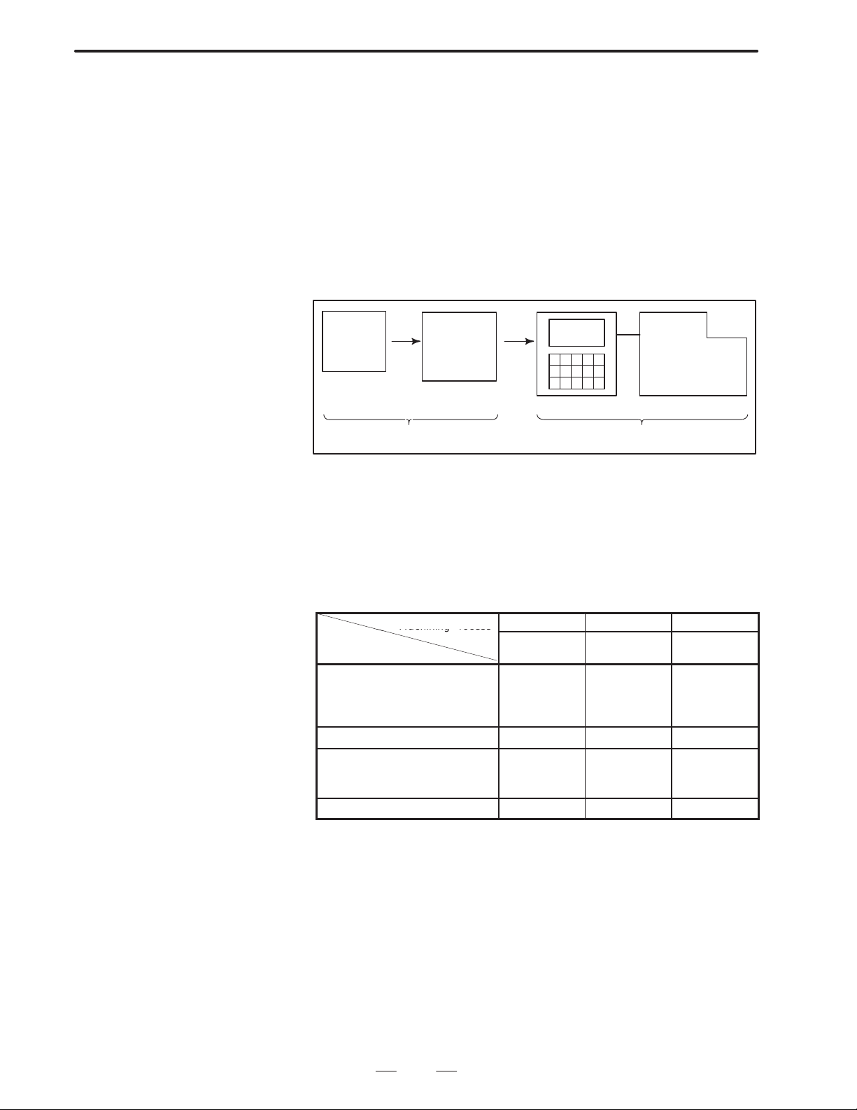
B–62764EN/01
Machining rocess
GENERAL
1. GENERAL
1.1
GENERAL FLOW
OF OPERATION OF
CNC MACHINE
TOOL
When machining the part using the CNC machine tool, first prepare the
program, then operate the CNC machine by using the program.
1) First, prepare the program from a part drawing to operate the CNC
machine tool.
How to prepare the program is described in the Chapter II.
PROGRAMMING.
2) The program is to be read into the CNC system. Then, mount the
workpieces and tools on the machine, and operate the tools according
to the programming. Finally, execute the machining actually.
How to operate the CNC system is described in the Chapter III.
OPERATION.
Part
drawing
CHAPTER II PROGRAMMING CHAPTER III OPERATION
Part
programming
CNC
MACHINE TOOL
Before the actual programming, make the machining plan for how to
machine the part.
Machining plan
1. Determination of workpieces machining range
2. Method of mounting workpieces on the machine tool
3. Machining sequence in every machining process
4. Machining tools and machining
Decide the machining method in every machining process.
Machining process
Machining procedure
1. Machining method
: Rough
Semi
Finish
2. Machining tools
3. Machining conditions
: Feedrate
Cutting depth
4. Tool path
1 2 3
Feed cutting Side cutting
Hole
machining
5
Page 29
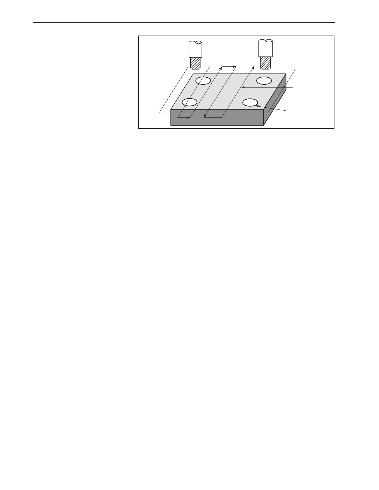
1. GENERAL
GENERAL
Tool
Side cutting
B–62764EN/01
Face cutting
Hole machining
Prepare the program of the tool path and machining condition
according to the workpiece figure, for each machining.
6
Page 30

B–62764EN/01
1.2
NOTES ON READING THIS MANUAL
GENERAL
NOTE
1 The function of an CNC machine tool system depends not
only on the CNC, but on the combination of the machine
tool, its magnetic cabinet, the servo system, the CNC, the
operator’s panels, etc. It is too difficult to describe the
function, programming, and operation relating to all
combinations. This manual generally describes these from
the stand–point of the CNC. So, for details on a particular
CNC machine tool, refer to the manual issued by the
machine tool builder, which should take precedence over
this manual.
2 Headings are placed in the left margin so that the reader can
easily access necessary information. When locating the
necessary information, the reader can save time by
searching though these headings.
3 Machining programs, parameters, variables, etc. are stored
in the CNC unit internal non–volatile memory. In general,
these contents are not lost by the switching ON/OFF of the
power. However, it is possible that a state can occur where
precious data stored in the non–volatile memory has to be
deleted, because of deletions from a maloperation, or by a
failure restoration. In order to restore rapidly when this kind
of mishap occurs, it is recommended that you create a copy
of the various kinds of data beforehand.
4 This manual describes as many reasonable variations in
equipment usage as possible. It cannot address every
combination of features, options and commands that
should not be attempted.
If a particular combination of operations is not described, it
should not be attempted.
1. GENERAL
7
Page 31

II. PROGRAMMING
Page 32

B–62764EN/01
1
PROGRAMMING
1. GENERAL
11
Page 33

1. GENERAL
PROGRAMMING
B–62764EN/01
1.1
TOOL MOVEMENT
ALONG WORKPIECE
PARTS FIGURE–
INTERPOLATION
Explanations
D Tool movement along a
straight line
The tool moves along straight lines and arcs constituting the workpiece
parts figure (See II–4).
The function of moving the tool along straight lines and arcs is called the
interpolation.
Tool
Workpiece
Fig.1.1 (a) Tool movement along a straight line
Program
G01 X_ _ Y_ _ ;
X_ _ ;
D Tool movement along an
arc
Program
G03X_ _Y_ _R_ _;
Tool
Workpiece
Fig. 1.1 (b) T ool movement along an arc
12
Page 34

B–62764EN/01
PROGRAMMING
1. GENERAL
Symbols of the programmed commands G01, G02, ... are called the
preparatory function and specify the type of interpolation conducted in
the control unit.
(a) Movement along straight line
G01 Y_ _;
X– –Y– – – –;
Control unit
Interpolation
a)Movement
along straight
line
b)Movement
along arc
Fig. 1.1 (c) Interpolation function
(b) Movement along arc
G03X––Y––R––;
X axis
Y axis
Tool
movement
NOTE
Some machines move tables instead of tools but this
manual assumes that tools are moved against workpieces.
13
Page 35

1. GENERAL
PROGRAMMING
B–62764EN/01
1.2
FEED–
FEED FUNCTION
Movement of the tool at a specified speed for cutting a workpiece is called
the feed.
mm/min
F
Workpiece
Table
Fig. 1.2 (a) Feed function
Tool
Feedrates can be specified by using actual numerics. For example, to feed
the tool at a rate of 150 mm/min, specify the following in the program:
F150.0
The function of deciding the feed rate is called the feed function (See
II–5).
14
Page 36

B–62764EN/01
1.3
PART DRAWING AND
TOOL MOVEMENT
PROGRAMMING
1. GENERAL
1.3.1
Reference Position
(Machine–Specific
Position)
A CNC machine tool is provided with a fixed position. Normally, tool
change and programming of absolute zero point as described later are
performed at this position. This position is called the reference position.
Reference position
Tool
Workpiece
Table
Fig. 1.3 (a) Reference position
The tool can be moved to the reference position in two ways:
(1)Manual reference position return (See III–3.1)
Reference position return is performed by manual button operation.
(2)Automatic reference position return (See II–6)
In general, manual reference position return is performed first after the
power is turned on. In order to move the tool to the reference position
for tool change thereafter, the function of automatic reference position
return is used.
15
Page 37

1. GENERAL
1.3.2
Coordinate System on
Part Drawing and
Coordinate System
Specified by CNC –
Coordinate System
PROGRAMMING
Z
B–62764EN/01
Z
Y
Program
Y
Explanations
D Coordinate system
X
Part drawing
Fig. 1.3.2 (a)
X
Coordinate system
CNC
Command
Tool
Z
Y
Workpiece
X
Machine tool
Coordinate system
The following two coordinate systems are specified at different locations:
(See II–8)
(1)Coordinate system on part drawing
The coordinate system is written on the part drawing. As the program
data, the coordinate values on this coordinate system are used.
(2)Coordinate system specified by the CNC
The coordinate system is prepared on the actual machine tool table.
This can be achieved by programming the distance from the current
position of the tool to the zero point of the coordinate system to be set.
Y
230
300
Program
zero point
Fig. 1.3.2 (b) Coordinate system specified by the CNC
16
Present tool position
Distance to the zero point of a coordinate system to be set
X
Page 38

B–62764EN/01
PROGRAMMING
1. GENERAL
The positional relation between these two coordinate systems is
determined when a workpiece is set on the table.
Coordinate system on
part drawing established on the work-
Coordinate system specified by the CNC established on the table
Table
Fig. 1.3.2 (c) Coordinate system specified by CNC and coordinate
systemon part drawing
Y
Y
Workpiece
piece
X
X
D Methods of setting the
two coordinate systems
in the same position
The tool moves on the coordinate system specified by the CNC in
accordance with the command program generated with respect to the
coordinate system on the part drawing, and cuts a workpiece into a shape
on the drawing.
Therefore, in order to correctly cut the workpiece as specified on the
drawing, the two coordinate systems must be set at the same position.
To set the two coordinate systems at the same position, simple methods
shall be used according to workpiece shape, the number of machinings.
(1)Using a standard plane and point of the workpiece.
Y
Fixed distance
Program
zero point
Bring the tool center to the workpiece standard point.
And set the coordinate system specified by CNC at this position.
Workpiece’s
standard point
Fixed distance
X
17
Page 39

1. GENERAL
PROGRAMMING
B–62764EN/01
(2)Mounting a workpiece directly against the jig
Program zero point
Jig
Meet the tool center to the reference position. And set the coordinate system
specified by CNC at this position. (Jig shall be mounted on the predetermined
point from the reference position.)
(3)Mounting a workpiece on a pallet, then mounting the workpiece and
pallet on the jig
Pallet
Jig
Workpiece
(Jig and coordinate system shall be specified by the same as (2)).
18
Page 40

B–62764EN/01
1.3.3
How to Indicate
Command Dimensions
for Moving the Tool –
Absolute, Incremental
Commands
PROGRAMMING
1. GENERAL
Explanations
D Absolute command
Command for moving the tool can be indicated by absolute command or
incremental command (See II–9.1).
The tool moves to a point at “the distance from zero point of the
coordinate system” that is to the position of the coordinate values.
Z
X
Command specifying movement from
point A to point B
B(10.0,30.0,20.0)
G90 X10.0 Y30.0 Z20.0 ;
Coordinates of point B
Tool
A
D Incremental command
Specify the distance from the previous tool position to the next tool
position.
Z
Tool
A
X=40.0
Z=–10.0
B
X
Command specifying movement from
point A to point B
19
Y=–30.0
G91 X40.0 Y–30.0 Z–10.0
Distance and direction for
movement along each axis
;
Page 41

1. GENERAL
PROGRAMMING
B–62764EN/01
1.4
CUTTING SPEED –
SPINDLE SPEED
FUNCTION
Examples
The speed of the tool with respect to the workpiece when the workpiece
is cut is called the cutting speed.
As for the CNC, the cutting speed can be specified by the spindle speed
in rpm unit.
Tool
Spindle speed N
rpm
Workpiece
Tool diameter
D mm
V: Cutting speed
m/min
<When a workpiece should be machined with a tool 100 mm in
diameter at a cutting speed of 80 m/min. >
The spindle speed is approximately 250 rpm, which is obtained from
N=1000v/πD. Hence the following command is required:
S250;
Commands related to the spindle speed are called the spindle speed
function ( See II–10) .
20
Page 42

B–62764EN/01
PROGRAMMING
1. GENERAL
1.5
SELECTION OF TOOL
USED FOR VARIOUS
MACHINING – TOOL
FUNCTION
Examples
When drilling, tapping, boring, milling or the like, is performed, it is
necessary to select a suitable tool. When a number is assigned to each tool
and the number is specified in the program, the corresponding tool is
selected.
Tool number
01
02
A TC magazine
<When No.01 is assigned to a drilling tool>
When the tool is stored at location 01 in the ATC magazine, the tool
can be selected by specifying T01. This is called the tool function (See
II–11).
21
Page 43

1. GENERAL
PROGRAMMING
B–62764EN/01
1.6
COMMAND FOR
MACHINE
OPERATIONS –
MISCELLANEOUS
FUNCTION
When machining is actually started, it is necessary to rotate the spindle,
and feed coolant. For this purpose, on–off operations of spindle motor and
coolant valve should be controlled.
Tool
Coolant
Workpiece
The function of specifying the on–off operations of the components of the
machine is called the miscellaneous function. In general, the function is
specified by an M code (See II–12).
For example, when M03 is specified, the spindle is rotated clockwise at
the specified spindle speed.
22
Page 44

B–62764EN/01
PROGRAMMING
1. GENERAL
1.7
PROGRAM CONFIGURATION
A group of commands given to the CNC for operating the machine is
called the program. By specifying the commands, the tool is moved along
a straight line or an arc, or the spindle motor is turned on and off.
In the program, specify the commands in the sequence of actual tool
movements.
Block
Block
Tool movement sequence
Block
Program
Fig. 1.7 (a) Program configuration
Block
⋅
⋅
⋅
⋅
Block
A group of commands at each step of the sequence is called the block.
The program consists of a group of blocks for a series of machining. The
number for discriminating each block is called the sequence number, and
the number for discriminating each program is called the program
number (See II–13).
23
Page 45

1. GENERAL
PROGRAMMING
B–62764EN/01
Explanations
D Block
D Program
The block and the program have the following configurations.
1 block
N ffff G ff Xff.f Yfff.f M ff S ff T ff ;
Sequence
number
Preparatory
function
Dimension word Miscel-
laneous
function
Fig. 1.7 (b) Block configuration
Spindle
function
Tool
function
End of
block
A block starts with a sequence number to identify the block and ends with
an end–of–block code.
This manual indicates the end–of–block code by ; (LF in the ISO code and
CR in the EIA code).
;
Offff;
⋅
⋅
⋅
M30 ;
Fig. 1.7 (c) Program configuration
Program number
Bloc
k
Bloc
k
⋅
Bloc
⋅
k
⋅
End of program
Normally , a program number is specified after the end–of–block (;) code
at the beginning of the program, and a program end code (M02 or M30)
is specified at the end of the program.
24
Page 46

B–62764EN/01
PROGRAMMING
1. GENERAL
D Main program and
subprogram
When machining of the same pattern appears at many portions of a
program, a program for the pattern is created. This is called the
subprogram. On the other hand, the original program is called the main
program. When a subprogram execution command appears during
execution of the main program, commands of the subprogram are
executed. When execution of the subprogram is finished, the sequence
returns to the main program.
Main program
⋅
⋅
M98P1001
⋅
⋅
⋅
M98P1002
⋅
⋅
⋅
M98P1001
⋅
⋅
Subprogram #1
O1001
M99
Subprogram #2
O1002
Program for
hole #1
Program for
hole #2
⋅
M99
Hole #1
Hole #1
Hole #2
Hole #2
25
Page 47

1. GENERAL
1.8
TOOL FIGURE AND TOOL MOTION BY PROGRAM
Explanations
PROGRAMMING
B–62764EN/01
D Machining using the end
of cutter – Tool length
compensation function
(See II–15.1)
D Machining using the side
of cutter – Cutter
compensation function
(See II–15.4,15.5,15.6)
Usually, several tools are used for machining one workpiece. The tools
have different tool length. It is very troublesome to change the program
in accordance with the tools.
Therefore, the length of each tool used should be measured in advance.
By setting the difference between the length of the standard tool and the
length of each tool in the CNC (data display and setting : see III–11),
machining can be performed without altering the program even when the
tool is changed. This function is called tool length compensation.
Standard
tool
H1
H2
Workpiece
H3 H4
Because a cutter has a radius, the center of the cutter path goes around the
workpiece with the cutter radius deviated.
Cutter path using cutter
compensation
Machined part
figure
Workpiece
Cutter
If radius of cutters are stored in the CNC (Data Display and Setting : see
III–11), the tool can be moved by cutter radius apart from the machining
part figure. This function is called cutter compensation.
26
Page 48

B–62764EN/01
PROGRAMMING
1. GENERAL
1.9
TOOL MOVEMENT
RANGE – STROKE
Limit switches are installed at the ends of each axis on the machine to
prevent tools from moving beyond the ends. The range in which tools can
move is called the stroke.
Table
Motor
Limit switch
Machine zero point
Specify these distances.
Tools cannot enter this area. The area is specified by data in memory or
a program.
Besides strokes defined with limit switches, the operator can define an
area which the tool cannot enter using a program or data in memory . This
function is called stroke check (see III–6.3).
27
Page 49

2. CONTROLLED AXES
CONTROLLED AXES
2
PROGRAMMING
B–62764EN/01
28
Page 50

B–62764EN/01
2.1
CONTROLLED AXES
PROGRAMMING
2. CONTROLLED AXES
Series 16, Series 160
Series 18, Series 180
Item
No. of basic controlled
axes
Controlled axes
expansion (total)
Basic simultaneously
controlled axes
Simultaneously controlled
axes expansion (total)
16–MC
160–MC
3 axes
Max. 8 axes
(included in Cs axis)
2 axes
Max. 6 axes Max. 6 axes for each path
16–MC, 160–MC
(two–path control)
3 axes for each path
(6 axes in total)
Max. 7 axes for each path
(Feed 6 axes + Cs axis)
2 axes for each path
(4 axes in total)
NOTE
The number of simultaneously controllable axes for manual
operation jog feed, manual reference position return, or
manual rapid traverse) is 1 or 3 (1 when bit 0 (JAX) of
parameter 1002 is set to 0 and 3 when it is set to 1).
Item 18–MC, 180–MC
No. of basic controlled axes 3 axes
Controlled axes expansion (total)
Basic simultaneously controlled axes 2 axes
Simultaneously controlled axes expansion (total) Max. 4 axes
Max. 6 axes
(included in Cs axis)
2.2
AXIS NAME
NOTE
The number of simultaneously controllable axes for manual
operation jog feed, manual reference position return, or
manual rapid traverse) is 1 or 3 (1 when bit 0 (JAX) of
parameter 1002 is set to 0 and 3 when it is set to 1).
The user can assign any one of the following nine characters as the axis
name: A, B, C, U, V, W, X, Y, and Z.Parameter No. 1020 is used to
determine the name of each axis.
When this parameter is set to 0 or a character other than the valid
characters is specified, an axis name from 1 to 8 is assigned by default.
In two–path control, the basic three axis names are fixed to X, Y, and Z
for either path, but the name of an additional axis can be selected from A,
B, C, U, V, and W by parameter 1020. Duplicate axis names cannot be
used in the same path, but the same axis name can be used in different
paths.
29
Page 51

2. CONTROLLED AXES
Limitations
PROGRAMMING
B–62764EN/01
D Default axis name
D Duplicate axis names
When a default axis name (1 to 8) is used, operation in the MEM mode
and MDI mode is disabled.
If a duplicate axis name is specified in the parameter, operation is enabled
only for the axis specified first.
NOTE
In two–path control, axis information displayed on the CRT
screen, such as the current position, may contain an axis
name with a suffix indicating the related path (X1, X2, etc).
This is intended to provide a comprehensible indication of
the path to which the axis belongs. The suffix cannot be
used in a program ; the axis name should be specified as X,
Y, Z, U, V, W, A, B, or C.
30
Page 52

B–62764EN/01
PROGRAMMING
2. CONTROLLED AXES
2.3
INCREMENT SYSTEM
The increment system consists of the least input increment (for input) and
least command increment (for output). The least input increment is the
least increment for programming the travel distance. The least command
increment is the least increment for moving the tool on the machine. Both
increments are represented in mm, inches, or deg.
Name of increment system
IS–B
Name of increment system
IS–C
Least input increment
0.001mm
0.0001inch
0.001deg
Least input incre-
ment
0.0001mm
0.00001inch
0.0001deg
Least command
increment
0.001mm
0.0001inch
0.001deg
Least command
increment
0.0001mm
0.00001inch
0.0001deg
Maximum
stroke
99999.999mm
9999.9999inch
99999.999deg
Maximum
stroke
9999.9999mm
999.99999inch
9999.9999deg
The least command increment is either metric or inch depending on the
machine tool. Set metric or inch to the parameter INM (No.100#0).
For selection between metric and inch for the least input increment, G
code (G20 or G21) or a setting parameter selects it.
Combined use of the inch system and the metric system is not allowed.
There are functions that cannot be used between axes with different unit
systems (circular interpolation, cutter compensation, etc.). For the
increment system, see the machine tool builder’s manual.
31
Page 53

2. CONTROLLED AXES
IS–B
IS–C
PROGRAMMING
B–62764EN/01
2.4
MAXIMUM STROKE
Maximum stroke = Least command increment 99999999
See 2.3 Incremen System.
Table 2.4(a) Maximum strokes
Increment system Maximum stroke
Metric machine system 99999.999 mm
99999.999 deg
–
Inch machine system 9999.9999 inch
99999.999 deg
Metric machine system 9999.9999 mm
9999.9999 deg
–
Inch machine system 999.99999 inch
9999.9999 deg
NOTE
1 A command exceeding the maximum stroke cannot be
specified.
2 The actual stroke depends on the machine tool.
32
Page 54

B–62764EN/01
3
3. PREP ARATORY FUNCTION
PROGRAMMING
PREPARATORY FUNCTION (G FUNCTION)
A number following address G determines the meaning of the command
for the concerned block.
G codes are divided into the following two types.
Type Meaning
One–shot G code The G code is effective only in the block in which it is
specified.
Modal G code The G code is effective until another G code of the
same group is specified.
(Example )
G01 and G00 are modal G codes in group 01.
(G FUNCTION)
G01X
Z
X
G00Z
G01 is effective in this range.
33
Page 55

3. PREPARATORY FUNCTION
(G FUNCTION)
PROGRAMMING
B–62764EN/01
Explanations
1. When the clear state (bit 6 (CLR) of parameter No. 3402) is set at
power–up or reset, the modal G codes are placed in the states
described below.
(1) The modal G codes are placed in the states marked with
as
indicated in Table 3.
(2) G20 and G21 remain unchanged when the clear state is set at
power–up or reset.
(3) Which status G22 or G23 at power on is set by parameter G23 (No.
3402#7). However, G22 and G23 remain unchanged when the
clear state is set at reset.
(4) The user can select G00 or G01 by setting bit 0 (G01) of parameter
No. 3402.
(5) The user can select G90 or G91 by setting bit 3 (G91) of parameter
No. 3402.
(6) The user can select G17, G18, or G19 by setting bit 1 (parameterG18)
and bit 2 (parameter G19) of parameter No. 3402.
2.G codes other than G10 and G11 are one–shot G codes.
3.When a G code not listed in the G code list is specified, or a G code
that has no corresponding option is specified, P/S alarm No. 010 is
output.
4.Multiple G codes can be specified in the same block if each G code
belongs to a different group. If multiple G codes that belong to the
same group are specified in the same block, only the last G code
specified is valid.
5.If a G code belonging to group 01 is specified in a canned cycle, the
canned cycle is cancelled. This means that the same state set by
specifying G80 is set. Note that the G codes in group 01 are not
affected by a G code specifying a canned cycle.
6.G codes are indicated by group.
34
Page 56

B–62764EN/01
01
00
25
17
06
04
24
00
3. PREP ARATORY FUNCTION
PROGRAMMING
Table 3 G code list (1/3)
G code
G00
G01
G02
G03
G02.2, G03.2
G02.3, G03.3
G04 Dwell, Exact stop
G05 High speed cycle machining
G07.1 (G107) Cylindrical interpolation
G08
G09
G10 Programmable data input
G10.6 Tool retract & recover
G11 Programmable data input mode cancel
G12.1
G13.1
G15
G16
G17
G18
G19
G20
G21
G22
G23
G25
G26
G27 Reference position return check
G28 Return to reference position
G29
G30
G30.1 Floating reference point return
G31 Skip function
G33 01 Thread cutting
Group Function
Positioning
Linear interpolation
02 ZpXp plane selection Yp: Y axis or its parallel axis
Circular interpolation/Helical interpolation CW
Circular interpolation/Helical interpolation CCW
Involute interpolation
Explanation interpolation
Look–ahead control
Exact stop
Polar coordinate interpolation mode
Polar coordinate interpolation cancel mode
Polar coordinates command cancel
Polar coordinates command
XpY p plane selection Xp: X axis or its parallel axis
Y pZp plane selection Zp: Z axis or its parallel axis
Input in inch
Input in mm
Stored stroke check function on
Stored stroke check function off
Spindle speed fluctuation detection off
Spindle speed fluctuation detection on
Return from reference position
2nd, 3rd and 4th reference position return
(G FUNCTION)
35
Page 57

3. PREPARATORY FUNCTION
00
08
00
11
22
00
15
(G FUNCTION)
G code
G37
G39
G40
G41
G42 Cutter compensation right
G40.1 (G150)
G41.1 (G151) 19 Normal direction control left side on
G42.1 (G152) Normal direction control right side on
G43
G44
G45 Tool offset increase
G46
G47
G48 Tool offset double decrease
G49
G50
G51
G50.1
G51.1
G52
G53
G54
G54.1 Additional workpiece coordinate system selection
G55
G56
G57 Workpiece coordinate system 4 selection
G58 Workpiece coordinate system 5 selection
G59 Workpiece coordinate system 6 selection
G60 00 Single direction positioning
G61 Exact stop mode
G62
G63
G64
PROGRAMMING
Table 3 G code list (2/3)
Group Function
Automatic tool length measurment
Corner offset circular interpolation
Cutter compensation cancel/Three dimensional compensation cancel
07
08 Tool length compensation cancel
14
Cutter compensation left/Three dimensional compensation
Normal direction control cancel mode
Tool length compensation + direction
Tool length compensation – direction
Tool offset decrease
Tool offset double increase
Scaling cancel
Scaling
Programmable mirror image cancel
Programmable mirror image
Local coordinate system setting
Machine coordinate system selection
Workpiece coordinate system 1 selection
Workpiece coordinate system 2 selection
Workpiece coordinate system 3 selection
Automatic corner override
Tapping mode
Cutting mode
B–62764EN/01
36
Page 58

B–62764EN/01
12
16
09
03
00
05
13
10
20
3. PREP ARATORY FUNCTION
PROGRAMMING
Table 3 G code list (3/3)
G code
G65 00 Macro call
G66
G67
G68
G69
G73
G74
G75 01 Plunge grinding cycle (for grinding machine)
G76
G77 Direct constant–dimension plunge grinding cycle(for grinding machine)
G78 01 Continuous–feed surface grinding cycle(for grinding machine)
G79 Intermittent–feed surface grinding cycle(for grinding machine)
G80
G81
G82 Drilling cycle or counter boring cycle
G83 Peck drilling cycle
G84
G85 Boring cycle
G86 Boring cycle
G87 Back boring cycle
G88 Boring cycle
G89 Boring cycle
G90
G91
G92
G92.1
G94
G95
G96
G97
G98
G99
G160
G161
Group Function
Macro modal call
Macro modal call cancel
Coordinate rotation
Coordinate rotation cancel
Peck drilling cycle
Counter tapping cycle
09
09
Fine boring cycle
Canned cycle cancel/external operation function cancel
Drilling cycle, spot boring cycle or external operation function
Tapping cycle
Absolute command
Increment command
Setting for work coordinate system or clamp at maximum spindle speed
Workpiece coordinate system preset
Feed per minute
Feed per rotation
Constant surface speed control
Constant surface speed control cancel
Return to initial point in canned cycle
Return to R point in canned cycle
In–feed control function cancel(for grinding machine)
In–feed control function(for grinding machine)
(G FUNCTION)
37
Page 59

4. INTERPOLA TION FUNCTIONS
INTERPOLATION FUNCTIONS
4
PROGRAMMING
B–62764EN/01
38
Page 60

B–62764EN/01
PROGRAMMING
4. INTERPOLA TION FUNCTIONS
4.1
POSITIONING (G00)
Format
Explanations
The G00 command moves a tool to the position in the workpiece system
specified with an absolute or an incremental command at a rapid traverse
rate.
In the absolute command, coordinate value of the end point is
programmed.
In the incremental command the distance the tool moves is programmed.
G00IP_;
IP_: For an absolute command, the coordinates of an end
position, and for an incremental commnad, the distance
the tool moves.
Either of the following tool paths can be selected according to bit 1 of
parameter LRP No. 1401.
D Nonlinear interpolation positioning
The tool is positioned with the rapid traverse rate for each axis
separately. The tool path is normally straight.
D Linear interpolation positioning
The tool path is the same as in linear interpolation (G01). The tool
is positioned within the shortest possible time at a speed that is not
more than the rapid traverse rate for each axis.
Start position
Linear interpolation positioning
End position
Non linear interpolation positioning
The rapid traverse rate in G00 command is set to the parameter No. 1420
for each axis independently by the machine tool builder. In the
posiitoning mode actuated by G00, the tool is accelerated to a
predetermined speed at the start of a block and is decelerated at the end
of a block. Execution proceeds to the next block after confirming the
in–position.
“In–position ” means that the feed motor is within the specified range.
This range is determined by the machine tool builder by setting to
parameter (No. 1826).
In–position check for each block can be disabled by setting bit 5 (NCI)
of parameter No.1601 accordingly.
39
Page 61

4. INTERPOLA TION FUNCTIONS
PROGRAMMING
B–62764EN/01
Limitations
The rapid traverse rate cannot be specified in the address F.
Even if linear interpolation positioning is specified, nonlinear
interpolation positioning is used in the following cases. Therefore, be
careful to ensure that the tool does not foul the workpiece.
D G28 specifying positioning between the reference and intermediate
positions.
D G53
40
Page 62

B–62764EN/01
PROGRAMMING
4. INTERPOLA TION FUNCTIONS
4.2
SINGLE DIRECTION POSITIONING (G60)
Format
For accurate positioning without play of the machine (backlash), final
positioning from one direction is available.
Overrun
Start position
Start position
End position
G60 IP_;
IP_ : For an absolute command, the coordinates of an end
position, and for an incremental commnad, the distance
the tool moves.
Temporary stop
Explanations
Examples
An overrun and a positioning direction are set by the parameter (No.
5440). Even when a commanded positioning direction coincides with
that set by the parameter, the tool stops once before the end point.
G60, which is an one–shot G–code, can be used as a modal G–code in
group 01 by setting 1 to the parameter (No. 5431 bit 0 MDL).
This setting can eliminate specifying a G60 command for every block.
Other specifications are the same as those for an one–shot G60 command.
When an one–shot G code is sepcified in the single direction positioning
mode, the one–shot G command is effective like G codes in group 01.
When one–shot
G60 commands are used.
G90;
G60 X0Y0;
G60 X100;
G60 Y100;
G04 X10;
G00 X0Y0;
Single direction
positioning
When modal
G60 command is used.
G90G60;
X0Y0;
X100;
Y100;
G04X10;
G00X0Y0;
Single direction
positioning mode start
Single direction
positioning
Dwell
Single direction
positioning
mode cancel
41
Page 63

4. INTERPOLA TION FUNCTIONS
PROGRAMMING
B–62764EN/01
Restrictions
D During canned cycle for drilling, no single direction positioning is
effected in Z axis.
D No single direction positioning is effected in an axis for which no
overrun has been set by the parameter.
D When the move distance 0 is commanded, the single direction
positioning is not performed.
D The direction set to the parameter is not effected by mirror image.
D The single direction positioning does not apply to the shift motion in
the canned cycles of G76 and G87.
42
Page 64

B–62764EN/01
PROGRAMMING
4. INTERPOLA TION FUNCTIONS
4.3
LINEAR
INTERPOLATION
(G01)
Format
Explanations
Tools can move along a line
G01 IP_F_;
IP_:For an absolute command, the coordinates of an end point ,
and for an incremental commnad, the distance the tool moves.
F_:Speed of tool feed (Feedrate)
A tools move along a line to the specified position at the feedrate
specified in F.
The feedrate specified in F is effective until a new value is specified. It
need not be specified for each block.
The feedrate commanded by the F code is measured along the tool path.
If the F code is not commanded, the feedrate is regarded as zero.
The feedrate of each axis direction is as follows.
G01ααββγγζζ
Feed rate of α axis direction :
Feed rate of Β axis direction :
Feed rate of Γ axis direction :
Feed rate of Ζ axis direction :
2
Ǹ
L + a
) b2) g2) z
Ff ;
a
Fa +
f
L
b
Fb+
f
L
g
Fg +
f
L
z
+
f
F
z
L
2
The feed rate of the rotary axis is commanded in the unit of deg/min (the
unit is decimal point position).
When the straight line axis α(such as X, Y, or Z) and the rotating axisβ
(such as A, B, or C) are linearly interpolated, the feed rate is that in which
the tangential feed rate in the αandβ cartesian coordinate system is
commanded by F(mm/min).
β–axis feedrate is obtained ; at first, the time required for distribution is
calculated by using the above fromula, then the β –axis feedrate unit is
changed to deg 1min.
43
Page 65

4. INTERPOLA TION FUNCTIONS
PROGRAMMING
B–62764EN/01
A calcula;tion example is as follows.
G91 G01 X20.0B40.0 F300.0 ;
This changes the unit of the C axis from 40.0 deg to 40mm with metric
input. The time required for distribution is calculated as follows:
Examples
D Linear interpolation
Ǹ
202) 40
The feed rate for the C axis is
300
40
0.14907
2
0.14907 (min)8
8
268.3 degńmin
In simultaneous 3 or 4 axes control, the feed rate is calculated the same
way as in 2 axes control.
(G91) G01X200.0Y100.0F200.0 ;
Y axis
100.0
(End position)
D Feedrate for the
rotation axis
(Start position)
G91G01C–90.0 G300.0 ;Feed rate of 300deg/min
(End point)
200.00
(Start point)
90°
Feedrate is 300 deg/min
X axis
44
Page 66

B–62764EN/01
PROGRAMMING
4. INTERPOLA TION FUNCTIONS
4.4
CIRCULAR
INTERPOLATION
(G02,G03)
Format
The command below will move a tool along a circular arc.
Arc in the XpYp plane
G17
Arc in the ZpXp plane
G18
Arc in the YpZp plane
G19
G02
G03
G02
G03
G02
G03
Xp_Yp_
Xp_ p_
Yp_ Zp_
I_ J_
R_
I_ K_
R_
J_ K_
R_
F_ ;
F_
F_
T able.4.4 Description of the Command Format
Command
G17 Specification of arc on XpYp plane
G18 Specification of arc on ZpXp plane
G19 Specification of arc on YpZp plane
G02 Circular Interpolation Clockwise direction (CW)
G03 Circular Interpolation Counterclockwise direction (CCW)
X
p_
Y
p_
Z
p_
I_ Xp axis distance from the start point to the center of an arc
J_ Yp axis distance from the start point to the center of an arc
Command values of X axis or its parallel axis
(set by parameter No. 1022)
Command values of Y axis or its parallel axis
(set by parameter No. 1022)
Command values of Z axis or its parallel axis
(set by parameter No. 1022)
with sign
with sign
Description
k_ Zp axis distance from the start point to the center of an arc
with sign
R_ Arc radius (with sign)
F_ Feedrate along the arc
45
Page 67

4. INTERPOLA TION FUNCTIONS
Explanations
PROGRAMMING
B–62764EN/01
D Direction of the circular
interpolation
D Distance moved on an
arc
D Distance from the start
point to the center of arc
“Clockwise”(G02) and “counterclockwise”(G03) on the XpYp plane
(Z
plane or YpZp plane) are defined when the XpYp plane is viewed
pXp
in the positive–to–negative direction of the Z
axis (Yp axis or Xp axis,
p
respectively) in the Cartesian coordinate system. See the figure below.
Yp Xp Zp
G18
G03
Zp
G03
G02
Yp
G19
G02
G17
G03
G02
Xp
The end point of an arc is specified by address Xp, Yp or Zp, and is
expressed as an absolute or incremental value according to G90 or G91.
For the incremental value, the distance of the end point which is viewed
from the start point of the arc is specified.
The arc center is specified by addresses I, J, and K for the Xp, Y p, and Zp
axes, respectively . The numerical value following I, J, or K, however, is
a vector component in which the arc center is seen from the start point,
and is always specified as an incremental value irrespective of G90 and
G91, as shown below.
I, J, and K must be signed according to the direction.
End point (x,y)
yx
x
Center
i
Start
point
j
I0,J0, and K0 can be omitted. When Xp, Yp , and Z
End point (z,x)
z
k
Center
Start
point
End point (y ,z)
z
y
i
Center
p
j
are omitted (the end
Start
point
k
point is the same as the start point) and the center is specified with I, J,
and K, a 360° arc (circle) is specified.
G021; Command for a circle
If the difference between the radius at the start point and that at the
end point exceeds the permitted value in a parameter (No.3410), an P/S
alarm (No.020) occurs.
46
Page 68

B–62764EN/01
PROGRAMMING
4. INTERPOLA TION FUNCTIONS
D
The distance between an arc and the center of a circle that contains the arc
can be specified using the radius, R, of the circle instead of I, J, and K.
In this case, one arc is less than 180°, and the other is more than 180° are
considered. When an arc exceeding 180° is commanded, the radius must
be specified with a negative value. If Xp, Yp, and Zp are all omitted, if
the end point is located at the same position as the start point and when
R is used, an arc of 0° is programmed
G02R ; (The cutter does not move.)
For arc (1)(less than 180°)
G91 G02 X
For arc (2)(greater than 180°)
G91 G02 X
60.0 YP20.0 R50.0 F300.0 ;
P
60.0 YP20.0 R–50.0 F300.0 ;
P
2
r=50mm
End point
1
D
Restrictions
Start point
r=50mm
Y
X
The feedrate in circular interpolation is equal to the feed rate specified by
the F code, and the feedrate along the arc (the tangential feedrate of the
arc) is controlled to be the specified feedrate.
The error between the specified feedrate and the actual tool feedrate is
±2% or less. However, this feed rate is measured along the arc after the
cutter compensation is applied
If I, J, K, and R addresses are specified simultaneously, the arc specified
by address R takes precedence and the other are ignored.
If an axis not comprising the specified plane is commanded, an alarm is
displayed.
For example, if axis U is specified as a parallel axis to X axis when plane
XY is specified, an P/S alarm (No.028)is displayed.
When an arc having a center angle approaching 180° is specified, the
calculated center coordinates may contain an error. In such a case, specify
the center of the arc with I, J, and K.
47
Page 69

4. INTERPOLA TION FUNCTIONS
PROGRAMMING
B–62764EN/01
Examples
Y axis
100
50R
140
60R
200
60
40
0
90 120
The above tool path can be programmed as follows ;
G92X200.0 Y40.0 Z0 ;
G90 G03 X140.0 Y100.0R60.0 F300.;
G02 X120.0 Y60.0R50.0 ;
or
G92X200.0 Y40.0Z0 ;
G90 G03 X140.0 Y100.0I-60.0 F300.;
G02 X120.0 Y60.0I-50.0 ;
G91 G03 X-60.0 Y60.0 R60.0 F300.;
G02 X-20.0 Y-40.0 R50.0 ;
or
G91 G03 X-60.0 Y60.0 I-60.0 F300. ;
G02 X-20.0 Y-40.0 I-50.0 ;
X axis
48
Page 70

B–62764EN/01
PROGRAMMING
4. INTERPOLA TION FUNCTIONS
4.5
HELICAL
INTERPOLATION
(G02,G03)
Format
Helical interpolation which moved helically is enabled by specifying up
to two other axes which move synchronously with the circular
interpolation by circular commands.
Synchronously with arc of XpYp plane
G17
Synchronously with arc of ZpXp plane
G18
Synchronously with arc of YpZp plane
G19
α,β:Any one axis where circular interpolation is not applied
G02
G03
G02
G03
G02
G03
Up to two other axes can be specified.
XpYp
XpZp
YpZp
IJ
R_
IK
JK
R
α(β)F
αβ)F_;
αβ)F;
.
Explanations
The command method is to simply or secondary add a move command
axis which is not circular interpolation axes. An F command specifies a
feed rate along a circular arc. Therefore, the feed rate of the linear axis
is as follows:
Length of linear axis
F×
Length of circular arc
Determine the feed rate so the linear axis feed rate does not exceed any
of the various limit values.Bit 0 (HFC) of parameter No. 1404 can be used
to prevent the linear axis feedrate from exceeding various limit values.
Z
Tool path
YX
Restrictions
The feedrate along the circumference of two circular interpolated axes is the specified feedrate.
⋅Cutter compensation is applied only for a circular arc.
⋅Tool offset and tool length compensation cannot be used in a block in
which a helical interpolation is commanded.
49
Page 71

4. INTERPOLA TION FUNCTIONS
PROGRAMMING
B–62764EN/01
4.6
POLAR
COORDINATE
INTERPOLATION
(G12.1,G13.1)
Format
D Specify G12.1 and G13.1
in Separate Blocks.
Explanations
D Polar coordinate
interpolation plane
Polar coordinate interpolation is a function that exercises contour control
in converting a command programmed in a Cartesian coordinate system
to the movement of a linear axis (movement of a tool) and the movement
of a rotary axis (rotation of a workpiece). This function is useful for
grinding a cam shaft.
G12.1 ;
G13.1 ;
Starts polar coordinate interpolation mode (enables polar
coordinate interpolation)
Specify linear or circular interpolation using coordinates in a
Cartesian coordinate system consisting of a linear axis and
rotary axis (virtual axis).
Polar coordinate interpolation mode is cancelled (for not
performing polar coordinate interpolation)
G12.1 starts the polar coordinate interpolation mode and selects a polar
coordinate interpolation plane (Fig. 4.6 (a)). Polar coordinate
interpolation is performed on this plane.
Rotary axis (virtual axis)
(unitmm or inch)
Linear axis
(unit:mm or inch)
Origin of the local coordinate system (G52 command)
(Or origin of the workpiece coordinate system)
Fig4.6 (a) Polar coordinate interpolation plane.
When the power is turned on or the system is reset, polar coordinate
interpolation is canceled (G13.1).
The linear and rotation axes for polar coordinate interpolation must be set
in parameters (No. 5460 and 5461) beforehand.
CAUTION
The plane used before G12.1 is specified (plane selected
by G17, G18, or G19) is canceled. It is restored when G13.1
(canceling polar coordinate interpolation) is specified.
When the system is reset, polar coordinate interpolation is
canceled and the plane specified by G17, G18, or G19 is
used.
50
Page 72

B–62764EN/01
PROGRAMMING
4. INTERPOLA TION FUNCTIONS
D Distance moved and
feedrate for polar
coordinate interpolation
The unit for coordinates
on the hypothetical axis is
the same as the unit for
the linear axis (mm/inch)
The unit for the feedrate
is mm/min or inch/min
D G codes which can be
specified in the polar
coordinate interpolation
mode
D Circular interpolation in
the polar coordinate
plane
D Movement along axes
not in the polar
coordinate interpolation
plane in the polar
coordinate interpolation
mode
In the polar coordinate interpolation mode, program commands are
specified with Cartesian coordinates on the polar coordinate interpolation
plane. The axis address for the rotation axis is used as the axis address
for the second axis (virtual axis) in the plane. Whether a diameter or
radius is specified for the first axis in the plane is the same as for the
rotation axis regardless of the specification for the first axis in the plane.
The virtual axis is at coordinate 0 immediately after G12.1 is specified.
Polar interpolation is started assuming the angle of 0 for the position of
the tool when G12.1 is specified.
Specify the feedrate as a speed (relative speed between the workpiece and
tool) tangential to the polar coordinate interpolation plane (Cartesian
coordinate system) using F.
G01 Linear interpolation. . . . . . . . . . . .
G02, G03 Circular interpolation. . . . . . . .
G04 Dwell, Exact stop. . . . . . . . . . . .
G40, G41, G42 Cutter compensation . . .
(Polar coordinate interpolation is applied to the path
after cutter compensation.)
G65, G66, G67 Custom macro command. . .
G90, G91 Absolute command, incremental command. . . . . . . .
G94, G95 Feed per minute, feed per revolution. . . . . . . .
The addresses for specifying the radius of an arc for circular interpolation
(G02 or G03) in the polar coordinate interpolation plane depend on the
first axis in the plane (linear axis).
⋅ I and J in the Xp–Yp plane when the linear axis is the X–axis or an axis
parallel to the X–axis.
⋅ J and K in the Y p–Zp plane when the linear axis is the Y–axis or an axis
parallel to the Y–axis.
⋅ K and I in the Zp–Xp plane when the linear axis is the Z–axis or an axis
parallel to the Z–axis.
The radius of an arc can be specified also with an R command.
The tool moves along such axes normally, independent of polar
coordinate interpolation.
D Current position display
in the polar coordinate
interpolation mode
Limitations
D Coordinate system for
the polar coordinate
interpolation
D Tool offset command
Actual coordinates are displayed. However, the remaining distance to
move in a block is displayed based on the coordinates in the polar
coordinate interpolation plane (Cartesian coordinates).
Before G12.1 is specified, a local coordinate system (or workpiece
coordinate system) where the center of the rotary axis is the origin of the
coordinate system must be set. In the G12.1 mode, the coordinate system
must not be changed (G92, G52, G53, relative coordinate reset, G54
through G59, etc.).
The polar coordinate interpolation mode cannot be started or terminated
(G12.1 or G13.1) in the tool offset mode (G41 or G42). G12.1 or G13.1
must be specified in the tool offset canceled mode (G40).
51
Page 73

4. INTERPOLA TION FUNCTIONS
PROGRAMMING
B–62764EN/01
D Tool length offset
command
D Tool offset command
D Program restart
D Cutting feedrate for the
rotation axis
WARNING
T ool length of fset must be specified in the polar coordinate interpolation
cancel mode before G12.1 is specified. It cannot be
specified in the polar coordinate interpolation mode. Furthermore, no
offset values can be changed in the polar coordinate interpolation mode.
A tool offset must be specified before the G12.1 mode is set. No offset
can be changed in the G12.1 mode.
For a block in the G12.1 mode, the program cannot be restarted.
Polar coordinate interpolation converts the tool movement for a figure
programmed in a Cartesian coordinate system to the tool movement in the
rotation axis (C–axis) and the linear axis (X–axis). When the tool moves
closer to the center of the workpiece, the C–axis component of the
feedrate becomes larger and may exceed the maximum cutting feedrate
for the C–axis (set in parameter (No. 1422)), causing an alarm (see the
figure below). To prevent the C–axis component from exceeding the
maximum cutting feedrate for the C–axis, reduce the feedrate specified
with address F or create a program so that the tool (center of the tool when
cutter compensation is applied) does not move close to the center of the
workpiece.
∆
X
θ1
θ2
θ3
L :Distance (in mm) between the tool center and workpiece center when the tool center is the nearest to the
workpiece center
R :Maximum cutting feedrate (deg/min) of the C axis
Then, a speed specifiable with address F in polar coordinate interpolation can be given by the formula below.
Specify a speed allowed by the formula. The formula provides a theoretical value; in practice, a value slightly
smaller than a theoretical value may need to be used due to a calculation error.
L
1
F < L × R ×
Consider lines L1, L2, and L3. ∆X is the distance the tool moves per time unit
at the feedrate specified with address F in the Cartesian coordinate system.
As the tool moves from L1 to L2 to L3, the angle at which the tool moves per
L
time unit corresponding to ∆X in the Cartesian coordinate system increases
2
fromθ1 toθ 2 to θ3.
L
In other words, the C–axis component of the feedrate becomes larger as the
3
tool moves closer to the center of the workpiece. The C component of the
feedrate may exceed the maximum cutting feedrate for the C–axis because
the tool movement in the Cartesian coordinate system has been converted to
the tool movement for the C–axis and the X–axis.
π
(mm/min)
180
52
Page 74

B–62764EN/01
PROGRAMMING
4. INTERPOLA TION FUNCTIONS
Examples
Example of Polar Coordinate Interpolation Program
Based on X Axis(Linear Axis) and C Axis (Rotary Axis)
C’(hypothetical axis)
N204
N205
N206
C axis
N203
N202 N201
N208
N207
Path after cutter compensation
Program path
N200
X axis
Tool
Z axis
O0001 ;
N010 T0101
N0100 G90 G00 X60.0 C0 Z_ ; Positioning to start position
N0200 G12.1 ; Start of polar coordinate interpolation
N0201 G42 G01 X20.0 F_ ;
N0202 C10.0 ;
N0203 G03 X10.0 C20.0 R10.0 ;
N0204 G01 X–20.0 ; Geometry program
N0205 C–10.0 ; (program based on cartesian coordinates on
N0206 G03 X–10.0 C–20.0 I10.0 J0 ; X–C’ plane)
N0207 G01 X20.0 ;
N0208 C0 ;
N0209 G40 X60.0 ;
N0210 G13.1 ; Cancellation of polar coordinate interpolation
N0300 Z_ ;
N0400 X_ C_ ;
N0900M30 ;
53
Page 75

4. INTERPOLA TION FUNCTIONS
PROGRAMMING
B–62764EN/01
4.7
CYLINDRICAL
INTERPOLATION
(G07.1)
Format
The amount of travel of a rotary axis specified by an angle is once
internally converted to a distance of a linear axis along the outer surface
so that linear interpolation or circular interpolation can be performed with
another axis. After interpolation, such a distance is converted back to the
amount of travel of the rotary axis.
The cylindrical interpolation function allows the side of a cylinder to be
developed for programming. So programs such as a program for
cylindrical cam grooving can be created very easily.
G07.1 IP r ; Starts the cylindrical interpolation mode
(enables cylindrical interpolation).
:
:
:
G07.1 IP 0 ; The cylindrical interpolation mode is cancelled.
IP : An address for the rotation axis
r : The radius of the cylinder
Specify G07.1 IP r ; and G07.1 IP 0; in separate blocks.
G107 can be used instead of G07.1.
Explanations
D Plane selection
(G17, G18, G19)
D
D Circular interpolation
(G02,G03)
Use parameter (No. 1022) to specify whether the rotation axis is the X–,
Y–, or Z–axis, or an axis parallel to one of these axes. Specify the G code
to select a plane for which the rotation axis is the specified linear axis.
For example, when the rotation axis is an axis parallel to the X–axis, G17
must specify an Xp–Y p plane, which is a plane defined by the rotation axis
and the Y–axis or an axis parallel to the Y–axis.
Only one rotation axis can be set for cylindrical interpolation.
A feedrate specified in the cylindrical interpolation mode is a speed on the
developed cylindrical surface.
In the cylindrical interpolation mode, circular interpolation is possible
with the rotation axis and another linear axis. Radius R is used in
commands in the same way as described in II–4.4.
The unit for a radius is not degrees but millimeters (for metric input) or
inches (for inch input).
< Example Circular interpolation between the Z axis and C axis >
For the C axis of parameter (No.1022), 5 (axis parallel with the X axis)
is to be set. In this case, the command for circular interpolation is
G18 Z__C__;
G02 (G03) Z__C__R__;
For the C axis of parameter (No.1022), 6 (axis parallel with the Y axis)
may be specified instead. In this case, however, the command for
circular interpolation is
G19 C__Z__;
G02 (G03) Z__C__R__;
54
Page 76

B–62764EN/01
PROGRAMMING
4. INTERPOLA TION FUNCTIONS
D Tool offset
D Cylindrical interpolation
accuracy
To perform tool offset in the cylindrical interpolation mode, cancel any
ongoing cutter compensation mode before entering the cylindrical
interpolation mode. Then, start and terminate tool offset within the
cylindrical interpolation mode.
In the cylindrical interpolation mode, the amount of travel of a rotary axis
specified by an angle is once internally converted to a distance of a linear
axis on the outer surface so that linear interpolation or circular
interpolation can be performed with another axis. After interpolation,
such a distance is converted back to an angle. For this conversion, the
amount of travel is rounded to a least input increment.
So when the radius of a cylinder is small, the actual amount of travel can
differ from a specified amount of travel. Note, however, that such an error
is not accumulative.
If manual operation is performed in the cylindrical interpolation mode
with manual absolute on, an error can occur for the reason described
above.
The actual amount
of travel
MOTION REV
R
MOTION REV
=
2×2πR
The amount of travel per rotation of the rotation axis (Set-
:
ting value of parameter No. 1260)
Workpiece radius
:
Specified value
2×2πR
MOTION REV
Limitations
D Arc radius specification
in the cylindrical
interpolation mode
D Circular interpolation
and cutter compensation
D Positioning
D Coordinate system
setting
D Cylindrical interpolation
mode setting
:Rounded to the least input increment
In the cylindrical interpolation mode, an arc radius cannot be specified
with word address I, J, or K.
If the cylindrical interpolation mode is started when cutter compensation
is already applied, circular interpolation is not correctly performed in the
cylindrical interpolation mode.
In the cylindrical interpolation mode, positioning operations (including
those that produce rapid traverse cycles such as G28, G53, G73, G74,
G76, G80 through G89) cannot be specified. Before positioning can be
specified, the cylindrical interpolation mode must be cancelled.
Cylindrical interpolation (G07.1) cannot be performed in the positioning
mode (G00).
In the cylindrical interpolation mode, a workpiece coordinate system
(G92, G54 through G59) or local coordinate system (G52) cannot be
specified.
In the cylindrical interpolation mode, the cylindrical interpolation mode
cannot be reset. The cylindrical interpolation mode must be cancelled
before the cylindrical interpolation mode can be reset.
D Tool offset
D Index table indexing
function
A tool offset must be specified before the cylindrical interpolation mode
is set. No offset can be changed in the cylindrical interpolation mode.
Cylindrical interpolation cannot be specified when the index table index
function is being used.
55
Page 77

4. INTERPOLA TION FUNCTIONS
Examples
PROGRAMMING
B–62764EN/01
Example of a Cylindrical Interpolation Program
O0001 (CYLINDRICAL INTERPOLATION );
N01 G00 G90 Z100.0 C0 ;
N02 G01 G91 G18 Z0 C0 ;
N03 G07.1 C57299 ;
N04 G90 G01 G42 Z120.0 D01 F250 ;
N05 C30.0 ;
N06 G02 Z90.0 C60.0 R30.0 ;
N07 G01 Z70.0 ;
N08 G03 Z60.0 C70.0 R10.0 ;
N09 G01 C150.0 ;
N10 G03 Z70.0 C190.0 R75.0 ;
N11 G01 Z110.0 C230.0 ;
N12 G02 Z120.0 C270.0 R75.0 ;
N13 G01 C360.0 ;
N14 G40 Z100.0 ;
N15 G07.1 C0 ;
N16 M30 ;
C
RZ
mm
120
110
90
70
60
Z
N05
N06
N11
N07
N08 N09 N10
0
30
60 70
150
N12
230190
270
N13
360
deg
C
56
Page 78

B–62764EN/01
PROGRAMMING
4. INTERPOLA TION FUNCTIONS
4.8
INVOLUTE
INTERPOLATION
(G02.2, G03.2)
Involute curve machining can be performed by using involute
interpolation. Involute interpolation ensures continuous pulse
distribution even in high–speed operation in small blocks, thus enabling
smooth and high–speed machining. Furthermore, machining tapes can
be created easily and efficiently, reducing the required length of tape.
57
Page 79

4. INTERPOLA TION FUNCTIONS
Format
PROGRAMMING
Involute interpolation on the X–Y plane
G17 G02.2 X__Y__I__J__R__F__ ;
G17 G03.2 X__Y__I__J__R__F__ ;
Involute interpolation on the Z–X plane
G18 G02.2 Z_
G18 G03.2 Z_
X__K__I__R__F__ ;
X__K__I__R__F__ ;
Involute interpolation on the Y–Z plane
G19 G02.2 Y__Z__J__K__R__F__ ;
G19 G03.2 Y__Z__J__K__R__F__ ;
Where,
G02.2: Involute interpolation (clockwise)
G03.2: Involute interpolation (counterclockwise)
G17/G18/G19 : X –Y / Z–X / Y–Z plane selection
X, Y, Z : Involute curve end coordinate
I, J, K : Center of the base circle for an involute curve viewed
from the start point
R : Base circle radius
F : Cutting feedrate
Yp Yp
B–62764EN/01
Start point
Ps
J
Base circle
Yp
P
e
End point
Po
Ps
I
End point
Pe
I
Po
0
R
Xp
R
0
Pe
J
End point
Clockwise involute interpolation (G02.2)
Yp
End point
Ro
J
I
Ps
Pe
Start point
I
J
0
R
Start point
Ps
Po
Xp Xp
R
0
Counterclockwise involute interpolation (G03.2)
Xp
58
Page 80

B–62764EN/01
Explanations
PROGRAMMING
4. INTERPOLA TION FUNCTIONS
D Involute curve
An involute curve on the X–Y plane is defined as follows ;
X (θ)=R [cos θ+ (θ-θ0 ) sin θ] +X
Y (θ)=R [sin θ- (θ-θ0 ) cos θ] +Y
0
0
where,
X0 , Y0: Coordinates of the center of a base circle
R:Base circle radius
θ0: Angle of the start point of an involute curve
θ : Angle of the point where a tangent from the current position
to the base circle contacts the base circle
X (θ), Y (θ): Current position on the X–axis and Y–axis
Y
Involute curve
Start point
(X,Y)
θ0
R
(X0,Y0)
Base circle
θ
End point
X
D Start point and end point
D Base circle specification
Fig.4.8 (a) Involute Curve
Involute curves on the Z–X plane and Y–Z plane are defined in the same
way as an involute curve on the X–Y plane.
The end point of an involute curve is specified using address X, Y, or Z.
An absolute value or incremental value is used to specify an X, Y, or Z
value. When using an incremental value, specify the coordinates of the
end point viewed from the start point of the involute curve.
When no end point is specified, P/S alarm No. 241 is issued.
If the specified start point or end point lies within the base circle, P/S
alarm No. 242 is issued. The same alarm is issued if cutter compensation
C causes the offset vector to enter the base circle. Be particularly careful
when applying an offset to the inside of an involute curve.
The center of a base circle is specified with I, J, and K, corresponding to
X, Y, and Z. The value following I, J, or K is a vector component defined
when the center of the base circle is viewed from the start point of the
involute curve; this value must always be specified as an incremental
value, regardless of the G90/G91 setting. Assign a sign to I, J, and K
according to the direction.
If I, J, and K are all left unspecified, or I0J0K0 is specified, P/S alarm No.
241 or No. 242 is issued.
If R is not specified, or R < 0, P/S alarm No. 241 or No. 242 is issued.
59
Page 81

4. INTERPOLA TION FUNCTIONS
PROGRAMMING
B–62764EN/01
D Choosing from two types
of involute curves
D Feedrate
D Plane selection
D Cutter compensation C
When only a start point and I, J, and K data are given, two types of involute
curves can be created. One type of involute curve extends towards the
base circle, and the other extends away from the base circle. When the
specified end point is closer to the center of the base circle than the start
point, the involute curve extends toward the base circle. In the opposite
case, the involute curve extends away from the base circle.
The cutting feedrate specified in an F code is used as the feedrate for
involute interpolation. The feedrate along the involute curve (feedrate
along the tangent to the involute curve) is controlled to satisfy the
specified feedrate.
As with circular interpolation, the plane to which to apply involute
interpolation can be selected using G17, G18, and G19.
Cutter compensation C can be applied to involute curve machining. As
with linear and circular interpolation, G40, G41, and G42 are used to
specify cutter compensation.
G40 : Cutter compensation cancel
G41 : Cutter compensation left
G42 : Cutter compensation right
Cutter compensation for an involute curve is implemented as described
below.
First, near the start point of an involute curve, an arc with a curvature close
to the curvature of the involute curve is found. Next, an offset intersection
between the arc and the linear line or arc in the previous block is found.
Similarly, an offset intersection is found near the end point. Then, the
involute curve passing through the two points is used as the tool center
path.
In involute interpolation mode, cutter compensation cannot be started or
cancelled.
Tool center path
Programmed
path
R
Start point
60
Arc with a curvature
closer to the curvature of the involute
curve near the start
point
Arc with a curvature closer to the
curvature of the involute curve near
the end point
End point
Page 82

B–62764EN/01
PROGRAMMING
4. INTERPOLA TION FUNCTIONS
D Specifiable G codes
D Modes that allow
involute interpolation
specification
D End point error
The following G codes can be specified in involute interpolation mode:
G04 : Dwell
G10 : Data setting
G17 : X–Y plane selection
G18 : Z–X plane selection
G19 : Y–Z plane selection
G65 : Macro call
G66 : Macro modal call
G67 : Macro modal call cancel
G90 : Absolute command
G91 : Incremental command
Involute interpolation can be specified in the following G code modes:
G41 : Cutter compensation left
G42 : Cutter compensation right
G51 : Scaling
G51.1 : Programmable mirror image
G68 : Coordinate rotation
As shown below the end point may not be located on an involute curve
that passes through the start point.
When an involute curve that passes through the start point deviates from
the involute curve that passes through the end point by more than the value
set in parameter No. 5610, P/S alarm No. 243 is issued.
When there is an end point error, the feedrate is not guaranteed.
Y
End point
Deviation
Fig. 4.8 (b) End Point Error in Counterclockwise Involute Interpolation (G03.2)
Pe
Path after correction
Start
point
Ps
Correct involute curve
X
61
Page 83

4. INTERPOLA TION FUNCTIONS
Limitations
PROGRAMMING
B–62764EN/01
D Number of involute curve
turns
D Unspecifiable functions
D Modes that do not allow
involute interpolation
specification
D Cutting accuracy
Both the start point and end point must be within 100 turns from the point
where the involute curve starts. An involute curve can be specified to
make one or more turns in a single block.
If the specified start point or end point is beyond 100 turns from the point
where the involute curve starts, P/S alarm No. 242 is issued.
In involute interpolation mode, chamfer corner R (with an arbitrary
angle), helical cutting, or axis–by–axis scaling functions cannot be
specified.
Involute interpolation cannot be used in the following modes:
G41.1 (G151) : Normal direction control left side on
G42.1 (G152) : Normal direction control right side on
G07.1 (G107) : Cylindrical interpolation
G12.1 : Polar coordinate interpolation mode
G16 : Polar coordinates command
G72.1 : Drawing copy
The curvature of an involute curve varies rather sharply near the base
circle. In such locations, a larger load is applied to the cutter when the
programmed feedrate is used for cutting; in this case, the surface produced
may be somewhat uneven
62
Page 84

B–62764EN/01
PROGRAMMING
4. INTERPOLA TION FUNCTIONS
4.9
EXPONENTIAL
INTERPOLATION
(G02.3, G03.3)
Exponential interpolation exponentially changes the rotation of a
workpiece with respect to movement on the rotary axis. Furthermore,
exponential interpolation performs linear interpolation with respect to
another axis. This enables tapered groove machining with a constant
helix angle (constant helix taper machining). This function is best suited
for grooving and grinding tools such as end mills.
Z
β2β
A
X (Linear axis)
β
3
1
Helix angle
= β2= β
β
1
X
3
Format
X
A (Rotary axis)
A
positive rotation (ω=0)
G02. 3 X__ Y__ Z__ I__ J__ K__ R__ F__ Q__ ;
Negative rotation (ω=1)
G03. 3 X__ Y__ Z__ I__ J__ K__ R__ F__ Q__ ;
X__; Specifies an end point with an absolute or incremental value.
Y__; Specifies an end point with an absolute or incremental value.
Z__; Specifies an end point with an absolute or incremental value.
I__ ; Specifies angl I (from 1to 89 deg in units of 0.001deg ).
J__ ; Specifies angle J (from 1 to 89 degin units of 0.001deg).
K__; Specifies the amount to divide the linear axis for exponential
interpolation (span value). Specify a positive value.
When no value is specified, the value specified in parameter
(No. 5643) is used.
R__; Specifies constant R for exponential interpolation.
F__; Specifies the initial feedrate.
Specified in the same way as an ordinary F code. Specify a
composite feedrate including a feedrate on the rotary axis.
Q__ ; Specifies the feedrate at the end point.
The same unit used for F is used. The CNC internally performs
interpolation between the initial feedrate (F) and final feedrate
(Q), depending on the travel distance on the linear axis.
63
Page 85

4. INTERPOLA TION FUNCTIONS
Explanations
PROGRAMMING
B–62764EN/01
D Exponential relational
expressions
Exponential relational expressions for a linear axis and rotary axis are
defined as follows:
θ
X(θ)=R (e –1)
A()=(–1)360
k
tan (I)
θ
2π
1
⋅⋅⋅⋅⋅⋅⋅⋅⋅⋅
⋅⋅⋅⋅⋅⋅⋅⋅⋅⋅
Movement on the linear axis (1)
Movement on the linear axis (2)
Where,
tan (J)
K =
tan (I)
ω=0/1 ⋅⋅⋅⋅⋅⋅⋅⋅⋅⋅⋅⋅⋅⋅⋅⋅⋅⋅⋅
R, I, and J are constants, and θ represents an angle (radian)
Rotation direction
The following is obtained from Expression (1)
(X)=Kln( +1)
Xtan (I)
R
When there is movement from X1 to X2 on the linear axis, the
amount of movement on the rotary axis is determined by :
X
tan (I)
= K{ ln ( +1) – ln ( +1)}
2
R
X
tan (I)
1
R
Specify Expressions (1) and (2) in the format described earlier.
X (linear axis)
Limitations
D Cases where linear
interpolation is
performed
D Tool length
compensation / cutter
compensation
X
A (rotary axis)
A
Even when the G02.3 or G03.3 mode is set, linear interpolation is
performed in the following cases:
S When the linear axis specified in parameter( No. 5641) is not specified,
or the amount of movement on the linear axis is 0
S When the rotary axis specified in parameter (No. 5642) is specified
S When the amount for dividing the linear axis (span value) is 0
Neither tool length compensation nor cutter compensation can be used in
the G02.3 and G03.3 modes.
64
Page 86

B–62764EN/01
Examples
PROGRAMMING
4. INTERPOLA TION FUNCTIONS
CAUTION
The amount for dividing the linear axis for exponential
interpolation (span value) affects figure precision. However ,
if an excessively small value is set, the machine may stop
during interpolation. Try to specify an optimal span value
depending on the machine being used.
Constant helix machining for producing a tapered figure
Z
I
B
r
J
A
X
U
X
Constant helix machining for producing a reverse tapered figure
I
B
X
r
J
U
X
A
Z
65
Page 87

4. INTERPOLA TION FUNCTIONS
PROGRAMMING
B–62764EN/01
Relational expressions
Z (θ) = { –Utan (I) }(e –1) +Z (0) (3)
X (θ) = { –Utan (I) }(e –1) (4)
A () = (–1)360
r
2
r
2
2π
θ
k
θ
k
θ
tan (B)
tan (I)
1
tan (I)
⋅⋅⋅⋅⋅⋅⋅⋅⋅⋅⋅
⋅⋅⋅⋅⋅⋅⋅⋅⋅⋅⋅⋅⋅⋅⋅⋅⋅⋅⋅⋅
where
tan (J)
K =
tan (I)
X (), Z (), A (): Absolute value on the X–axis, Z–axis, and
A–axis from the origin
r : Left end diameter
U : Excess length
I : T aper angle
B : Groove bottom taper angle
J : Helix angle
X : Amount of movement on the linear axis
: Helix direction (0: Positive, 1: Negative)
: Workpiece rotation angle
From expressions (3) and (4), the following is obtained ;
Z () = tan (B) X () + Z (0) (5)
⋅⋅⋅⋅⋅⋅⋅⋅⋅⋅⋅⋅⋅⋅⋅⋅⋅⋅⋅
The groove bottom taper angle (B) is determined from the end
point position on the X–axis and Z–axis according to Expression
5. The amount of movement on the Z–axis is determined from a
groove bottom taper angle (B) and X–axis position.
From Expressions (1) and (4), the following is determined:
R = r/2 – Utan (I) (6)
⋅⋅⋅⋅⋅⋅⋅⋅⋅⋅⋅⋅⋅⋅⋅⋅⋅⋅⋅
Constant R is determined from the left end diameter (r) and excess
length (U) according to Expression (6). Specify a taper angle (I) in
address I, and specify a helix angle (J) in address J. Note, however, that a negative value must be specified as the taper angle (I) for
constant helix machining in order to produce a reverse tapered figure. Select a helix direction with G02.3 or G03.3. The user can
perform constant helix machining to produce a tapered figure or a
reverse tapered figure.
66
Page 88

B–62764EN/01
PROGRAMMING
4. INTERPOLA TION FUNCTIONS
4.10
SMOOTH
INTERPOLATION
(G05.1)
Format
Either of two types of machining can be selected, depending on the
program command.
D For those portions where the accuracy of the figure is critical, such as
at corners, machining is performed exactly as specified by the program
command.
D For those portions having a large radius of curvature where a smooth
figure must becreated, points along the machining path are
interpolated with a smooth curve, calculated from the polygonal lines
specified with the program command (smooth interpolation).
Smooth interpolation can be specified when CDSP (bit 5 of parameter No.
8485) is set to 1 in high–speed contour control mode (between G05
P10000 and G05 P0). Smooth interpolation performed in high–speed
contour control mode is described below. For details of high–speed
contour control, see Section 20.5.
Starting of smooth interpolation mode
G05.1 Q2X0Y0Z0;
Cancelation of smooth interpolation mode
Explanations
D Characteristics of
smooth interpolation
G05.1 Q 0;
To machine a part having sculptured surfaces, such as metal moldings
used in automobiles and airplanes, a part program usually approximates
the sculptured surfaces with minute line segments. As shown in the
following figure, a sculptured curve is normally approximated using line
segments with a tolerance of about 10 m.
Enlarged
10 m
: Specified point
67
Page 89

4. INTERPOLA TION FUNCTIONS
PROGRAMMING
B–62764EN/01
When a program approximates a sculptured curve with line segments, the
length of each segment differs between those portions that have mainly
a small radius of curvature and those that have mainly a large radius of
curvature. The length of the line segments is short in those portions
having a small radius of curvature, while it is long in those portions
having a large radius of curvature. The high–precision contour control of
the FANUC Series 15 moves the tool along a programmed path thus
enabling highly precise machining. This means that the tool movement
precisely follows the line segments used to approximate a sculptured
curve. This may result in a non–smooth machined curve if control is
applied to machining a curve where the radius of curvature is large and
changes only gradually . Although this effect is caused by high–precision
machining, which precisely follows a pre–programmed path, the uneven
corners that result will be judged unsatisfactory when smooth surfaces are
required.
Profile Portions having
mainly a small radius
of curvature
Example of machined
parts
Length of line segment Short Long
Resulting surfaces pro-
duced using high–precision contour control
Automobile parts Decorative parts, such
Smooth surface even
when machining is performed exactly as specified by a program
mainly a large radius
as body side moldings
Uneven surfaces may
result when machining
is performed exactly as
specified by a program
Portions having
of curvature
Example of uneven surfaces (polygon) resulting from machining that
precisely follows the line segments.
In smooth interpolation mode, the CNC automatically determines,
according to the program command, whether an accurate figure is
required, such as at corners, or a smooth figure is required where the
radius of curvature is large. If a block specifies a travel distance or
direction which differs greatly from that in the preceding block, smooth
interpolation is not performed for that block. Linear interpolation is
performed exactly as specified by the program command. Programming
is thus very simple.
68
Page 90

B–62764EN/01
Examples
N17
PROGRAMMING
Interpolated by smooth curve
4. INTERPOLA TION FUNCTIONS
Linear interpolation
D Conditions for
performing smooth
interpolation
N1
N1
N2
N17
N2
N16
N3
N16
N15
N14
N4
Interpolated by smooth curve
N15
N14
N3
N4
N13
N5
N13
N5
N6
N6
N12
N12
N7
N7
N11
N8
N8
N10
N9
Linear interpolation
N11
N10
N9
Smooth interpolation is performed when all the following conditions are
satisfied. If any of the following conditions is not satisfied for a block,
that block is executed without smooth interpolation then the conditions
are checked for the next block.
D Commands which cancel
smooth interpolation
(1)The machining length specified in the block is shorter than the length
specified with parameter No. 8486.
(2)The machining length is other than 0.
(3)The modes are:
G01 : Linear interpolation
G13.1 : Polar coordinate interpolation cancel
G15 : Polar coordinate command cancel
G40 : Cutter compensation cancel
(except for 3–dimensional tool compensation)
G64 : Cutting mode
G80 : Canned cycle cancel
G94 : Feed per minute
(4)Machining is specified only along the axes specified with G05.1Q2.
(5) The block is judged to be unsuitable for smooth interpolation, as
performed with the internal algorithm of the CNC.
(1)Auxiliary and second auxiliary functions
(2)M98, M99 : Subprogram call
M198 : Calling a subprogram in external memory
69
Page 91

4. INTERPOLA TION FUNCTIONS
Limitations
PROGRAMMING
B–62764EN/01
D Controlled axes
D High–precision contour
control mode
Examples
Smooth interpolation can be specified only for the X–, Y–, and Z–axes
and any axes parallel to these axes (up to three axes at one time).
Commands for turning on and off smooth interpolation mode must be
executed in high–precision contour control mode.
Example program for smooth interpolation
G05 P10000 ; N10 X–1000 Z350 ;
. N11 X–1000 Z175 ;
. N12 X–1000 Z25 ;
G91 ; N13 X–1000 Z– 50 ;
G05. 1 Q2 X0 Y0 Z0 ; N14 X–1000 Z– 50 ;
N01 G01 X1000 Z–300 ; N15 X–1000 Z50 ;
N02 X1000 Z–200 ; N16 X–1000 Z200 ;
N03 X1000 Z–50 ; N17 X–1000 Z300 ;
N04 X1000 Z50 ; G05. 1 Q0 ;
N05 X1000 Z50 ; .
N06 X1000 Z–25 ; .
N07 X1000 Z–175 ; G05 P0 ;
N08 X1000 Z–350 ; .
N09 Y1000 ; .
N1
N17
N16
N2
N3
Interpolated by smooth curve
Interpolated by smooth curve
N5
N13
N6
N15
N14
N4
N12
N7
N11
N8
N10
N9
Linear interpolation
70
Page 92

B–62764EN/01
PROGRAMMING
4. INTERPOLA TION FUNCTIONS
4.11
HYPOTHETICAL AXIS
INTERPOLATION
(G07)
Format
Explanations
D Sine interpolation
In helical interpolation, when pulses are distributed with one of the
circular interpolation axes set to a hypothetical axis, sine interpolation is
enabled.
When one of the circular interpolation axes is set to a hypothetical axis,
pulse distribution causes the speed of movement along the remaining axis
to change sinusoidally. If the major axis for threading (the axis along
which the machine travels the longest distance) is set to a hypothetical
axis, threading with a fractional lead is enabled. The axis to be set as the
hypothetical axis is specified with G07.
G07 0; Hypothetical axis setting
G07 1; Hypothetical axis cancel
Where, is any one of the addresses of the controlled axes.
The axis is regarded as a hypothetical axis for the period of time from
the G07 0 command until the G07 1 command appears.
Suppose sine interpolation is performed for one cycle in the YZ plane.
The hypothetical axis is then the X axis.
2
X
+ Y2 = r2 (r is the radius of an arc.)
Y = r SIN (
2
Z )
1
(1 is the distance traveled along the Z–axis in one cycle.)
D Interlock, stroke limit,
and external
deceleration
D Handle interrupt
Y
r
0
2
2
1
Z
Interlock, stroke limit, and external deceleration can also apply to the
hypothetical axis.
An interrupt caused by the handle also applies to the hypothetical axis.
This means that movement for a handle interrupt is performed.
71
Page 93

4. INTERPOLA TION FUNCTIONS
Limitations
PROGRAMMING
B–62764EN/01
D Manual operation
D Move command
D Coordinate rotation
Examples
D Sine interpolation
The hypothetical axis can be used only in automatic operation. In manual
operation, it is not used, and movement takes place.
Specify hypothetical axis interpolation only in the incremental mode.
Hypothetical axis interpolation does not support coordinate rotation.
Y
10.0
0
20.0
Z
D Changing the feedrate to
form a sine curve
N001 G07 X0 ;
N002 G91 G17 G03 X–20.2 Y0.0 I–10.0 Z20.0 F100 ;
N003 G01 X10.0 ;
N004 G07 X1 ;
From the N002 to N003 blocks, the X–axis is set to a hypothetical axis.
The N002 block specifies helical cutting in which the Z–axis is the linear
axis. Since no movement takes place along the X axis, movement along
the Y–axis is performed while performing sine interpolation along the
Z–axis.
In the N003 block, there is no movement along the X–axis, and so the
machine dwells until interpolation terminates.
(Sample program)
G07Z0 ; The Z–axis is set to a hypothetical axis.
G02X0Z0I10.0F4. ; The feedrate on the X–axis changes sinusoidally.
G07Z1 ; The use of the Z–axis as a hypothetical axis is
canceled.
F
4.0
72
Xt
Page 94

B–62764EN/01
t
Inch i
t
PROGRAMMING
4. INTERPOLA TION FUNCTIONS
4.12
THREAD CUTTING (G33)
Format
Explanations
Straight threads with a constant lead can be cut. The position coder
mounted on the spindle reads the spindle speed in real–time. The read
spindle speed is converted to the feedrate per minute to feed the tool.
I
P
G33 _ F_ ;
F : Long axis direction lead
Z
X
In general, thread cutting is repeated along the same tool path in rough
cutting through finish cutting for a screw . Since thread cutting starts when
the position coder mounted on the spindle outputs a 1–turn signal,
threading is started at a fixed point and the tool path on the workpiece is
unchanged for repeated thread cutting. Note that the spindle speed must
remain constant from rough cutting through finish cutting. If not,
incorrect thread lead will occur.
In general, the lag of the servo system, etc. will produce somewhat
incorrect leads at the starting and ending points of a thread cut. To
compensate for this, a thread cutting length somewhat longer than
required should be specified.
Table 4.12 (a) lists the ranges for specifying the thread lead.
T able. 4.12 (a) Ranges of lead sizes that can be specified
mm inpu
npu
Least command
increment
0.001 mm F1 to F50000 (0.01 to 500.00mm)
0.0001 mm F1 to F50000 (0.01 to 500.00mm)
0.0001 inch F1 to F99999
0.00001 inch F1 to F99999
Command value range of the lead
(0.0001 to 9.9999inch)
(0.0001 to 9.9999inch)
73
Page 95

4. INTERPOLA TION FUNCTIONS
NOTE
1 The spindle speed is limited as follows :
PROGRAMMING
B–62764EN/01
1 spindle speed
Maximum feedrate
Thread lead
Spindle speed : rpm
Thread lead : mm or inch
Maximum feedrate : mm/min or inch/min ; maximum command–specified feedrate for
feed–per–minute mode or maximum feedrate that is determined based on mechanical
restrictions including those related to motors, whichever is smaller
2 Cutting feedrate override is not applied to the converted feedrate in all machining process from
rough cutting to finish cutting. The feedrate is fixed at 100%
3 The converted feedrate is limited by the upper feedrate specified.
4 Feed hold is disabled during threading. Pressing the feed hold key during thread cutting causes
the machine to stop at the end point of the next block after threading (that is, after the G33 mode
is terminated)
Examples
Thread cutting at a pitch of 1.5mm
G33 Z10. F1.5;
74
Page 96

B–62764EN/01
PROGRAMMING
4. INTERPOLA TION FUNCTIONS
4.13
SKIP FUNCTION(G31)
Format
Explanations
Linear interpolation can be commanded by specifying axial move
following the G31 command, like G01. If an external skip signal is input
during the execution of this command, execution of the command is
interrupted and the next block is executed.
The skip function is used when the end of machining is not programmed
but specified with a signal from the machine, for example, in grinding. It
is used also for measuring the dimensions of a workpiece.
G31 IP_ ;
G31: One–shot G code (If is effective only in the block in which it
is specified)
The coordinate values when the skip signal is turned on can be used in a
custom macro because they are stored in the custom macro system
variable #5061 to #5064, as follows:
#5061 X axis coordinate value
#5062 Y axis coordinate value
#5063 Z axis coordinate value
#5064 4th axis coordinate value
#5065 5th axis coordinate value
#5066 6th axis coordinate value
#5067 7th axis coordinate value
#5068 8th axis coordinate value
WARNING
Disable feedrate override, dry run, and automatic
acceleration/deceleration (however, these become
available by setting the parameter SKF No.6200#7 to 1.)
when the feedrate per minute is specified, allowing for an
error in the position of the tool when a skip signal is input.
These functions are enabled when the feedrate per rotation
is specified.
NOTE
If G31 command is issued while cutter compensation C is
applied, an P/S alarm of No.035 is displayed. Cancel the
cutter compensation with the G40 command before the G31
command is specified.
75
Page 97

4. INTERPOLA TION FUNCTIONS
Examples
D The next block to G31 is
an incremental
command
PROGRAMMING
G31 G91X100.0 F100;
Y50.0;
B–62764EN/01
D The next block to G31 is
an absolute command
for 1 axis
Skip signal is input here
Y
100.0
X
Fig.4.13 (a) The next block is an incremental command
G31 G90X200.00 F100;
Y100.0;
Skip signal is input here
Y100.0
50.0
Actual motion
Motion without skip signal
X200.0
D The next block to G31 is
an absolute command
for 2 axes
Actual motion
Motion without skip signal
Fig.4.13 (b) The next block is an absolute command for 1 axis
G31 G90X200.0 F100;
X300.0 Y100.0;
Y
Skip signal is input here
100
100 200 300
Fig 4.13 (c) The next block is an absolute command for 2 axes
(300,100)
Actual motion
Motion without skip signal
X
76
Page 98

B–62764EN/01
PROGRAMMING
4. INTERPOLA TION FUNCTIONS
4.14
MULTISTAGE SKIP
(G31)
Format
In a block specifying P1 to P4 after G31, the multistage skip function
stores coordinates in a custom macro variable when a skip signal (4–point
or 8–point ; 8–point when a high–speed skip signal is used) is turned on.
Parameters No. 6202 to No. 6205 can be used to select a 4–point or
8–point (when a high–speed skip signal is used) skip signal. One skip
signal can be set to match multiple Pn or Qn (n=1,2,3,4) as well as to
match a Pn or Qn on a one–to–one basis. Parameters DS1 to DS8 (No.
6206 #0A#7) can be used for dwell.
A skip signal from equipment such as a fixed–dimension size measuring
instrument can be used to skip programs being executed.
In plunge grinding, for example, a series of operations from rough
machining to spark–out can be performed automatically by applying a
skip signal each time rough machining, semi–fine machining,
fine–machining, or spark–out operation is completed.
Move command
G31 IP __ F __ P __ ;
IP
IP_ : End point
IP
F_ : Feedrate
P_ : P1–P4
Explanations
D Correspondence to skip
signals
Dwell
G04 X (U, P)__ (Q__)
;
X(U, P)_ : Dwell time
Q_ : Q1 – Q4
Multistage skip is caused by specifying P1, P2, P3, or P4 in a G31 block.
For an explanation of selecting (P1, P2, P3, or P4), refer to the manual
supplied by the machine tool builder.
Specifying Q1, Q2, Q3, or Q4 in G04 (dwell command) enables dwell
skip in a similar way to specifying G31. A skip may occur even if Q is
not specified. For an explanation of selecting (Q1, Q2, Q3, or Q4), refer
to the manual supplied by the machine tool builder.
Parameter Nos. 6202 to 6205 can be used to specify whether the 4–point
or 8–point skip signal is used (when a high–speed skip signal is used).
Specification is not limited to one–to–one correspondence. It is possible
to specify that one skip signal correspond to two or more Pn’s or Qn’s
(n=1, 2, 3, 4). Also, bits 0 (DS1) to 7 (DS8) of parameter No. 6206 can
be used to specify dwell.
CAUTION
Dwell is not skipped when Qn is not specified and
parameters DS1–DS8 (No. 6206#0–#7) are not set.
77
Page 99

4. INTERPOLA TION FUNCTIONS
PROGRAMMING
B–62764EN/01
4.15
HIGH SPEED SKIP
SIGNAL (G31)
Format
The skip function operates based on a high–speed skip signal (connected
directly to the NC; not via the PMC) instead of an ordinary skip signal.
In this case, up to eight signals can be input.
Delay and error of skip signal input is 0 – 2 msec at the NC side (not
considering those at the PMC side).
This high–speed skip signal input function keeps this value to 0.1 msec
or less, thus allowing high precision measurement.
For details, refer to the appropriate manual supplied from the machine
tool builder.
G31 IP_ ;
IP
G31: One–shot G code (If is effective only in the block in which it is
specified)
78
Page 100

B–62764EN/01
PROGRAMMING
4. INTERPOLA TION FUNCTIONS
4.16
CONTINUOUS
HIGH–SPEED SKIP
FUNCTION (G31)
Format
Explanations
D Custom macro variables
The continuous high–speed skip function enables reading of absolute
coordinates by using the high–speed skip signal. Once a high–speed skip
signal has been input in a G31P90 block, absolute coordinates are read
into custom macro variables #5061 to #5068. The input of a skip signal
does not stops axial movement, thus enabling reading of the coordinates
of two or more points.
The rising and falling edges of the high–speed skip signal can be used as
a trigger, depending on the parameter BHIS (No. 6201#5) setting.
G31 P90 __ F__
__: Skip axis address and amount of travel
Only one axis can be specified. G31 is a one–shot G code.
Once a high–speed skip signal has been input in a G31P90 block, absolute
coordinates are read into custom macro variables #5061 to #5068. These
variables are immediately updated once the tool reaches the next skip
position. The feedrate must, therefore, be specified such that the tool does
not reach the next skip position before the application completes reading
of the variables. For details of the application, refer to the appropriate
manual supplied from the machine tool builder.
D High–speed skip signal
D End of block
Limitations
D Controlled axes
#5061 Coordinate along the first axis
#5062 Coordinate along the second axis
#5063 Coordinate along the third axis
#5068 Coordinate along the eighth axis
This function is enabled only when a high–speed skip signal is used.
The high–speed skip signal to be used is selected with bits 0 to 7 of
parameter No. 6208 (9S1 to 9S8).
The G31P90 block is terminated when the tool reaches the end point.
Only one axis can be specified in the block for the continuous high–speed
skip function (G31P90). If two or more axes are specified, P/S alarm No.
5068 is issued.
79
 Loading...