

Page 1

GE Fanuc Automation
Computer Numerical Control Products
Series 16 / 18 / 160 / 180 – Model C
for Lathe
Operator's Manual
B-62754EN/01 December 1995
Page 2

Warnings, Cautions, and Notes
as Used in this Publication
Warning notices are used in this publication to emphasize that hazardous voltages, currents,
temperatures, or other conditions that could cause personal injury exist in this equipment or
may be associated with its use.
In situations where inattention could cause either personal injury or damage to equipment, a
Warning notice is used.
Caution notices are used where equipment might be damaged if care is not taken.
GFL-001
Warning
Caution
Note
Notes merely call attention to information that is especially significant to understanding and
operating the equipment.
This document is based on information available at the time of its publication. While efforts
have been made to be accurate, the information contained herein does not purport to cover all
details or variations in hardware or software, nor to provide for every possible contingency in
connection with installation, operation, or maintenance. Features may be described herein
which are not present in all hardware and software systems. GE Fanuc Automation assumes
no obligation of notice to holders of this document with respect to changes subsequently made.
GE Fanuc Automation makes no representation or warranty, expressed, implied, or statutory
with respect to, and assumes no responsibility for the accuracy, completeness, sufficiency, or
usefulness of the information contained herein. No warranties of merchantability or fitness for
purpose shall apply.
©Copyright 1995 GE Fanuc Automation North America, Inc.
All Rights Reserved.
Page 3

SAFETY PRECAUTIONS
This section describes the safety precautions related to the use of CNC units. It is essential that these precautions
be observed by users to ensure the safe operation of machines equipped with a CNC unit (all descriptions in this
section assume this configuration). Note that some precautions are related only to specific functions, and thus
may not be applicable to certain CNC units.
Users must also observe the safety precautions related to the machine, as described in the relevant manual supplied
by the machine tool builder. Before attempting to operate the machine or create a program to control the operation
of the machine, the operator must become fully familiar with the contents of this manual and relevant manual
supplied by the machine tool builder.
Contents
1. DEFINITION OF WARNING, CAUTION, AND NOTE s–2. . . . . . . . . . . . . . . . . . . . . . . .
2. GENERAL WARNINGS AND CAUTIONS s–3. . . . . . . . . . . . . . . . . . . . . . . . . . . . . . . . .
3. WARNINGS AND CAUTIONS RELATED TO PROGRAMMING s–5. . . . . . . . . . . . . .
4. WARNINGS AND CAUTIONS RELATED TO HANDLING s–7. . . . . . . . . . . . . . . . . . . .
5. WARNINGS RELATED TO DAILY MAINTENANCE s–9. . . . . . . . . . . . . . . . . . . . . . . . .
s–1
Page 4

1
SAFETY PRECAUTIONS
B–62754EN/01
DEFINITION OF WARNING, CAUTION, AND NOTE
This manual includes safety precautions for protecting the user and preventing damage to the
machine. Precautions are classified into W arning and Caution according to their bearing on safety.
Also, supplementary information is described as a Note. Read the Warning, Caution, and Note
thoroughly before attempting to use the machine.
WARNING
Applied when there is a danger of the user being injured or when there is a damage of both the user
being injured and the equipment being damaged if the approved procedure is not observed.
CAUTION
Applied when there is a danger of the equipment being damaged, if the approved procedure is not
observed.
NOTE
The Note is used to indicate supplementary information other than Warning and Caution.
Read this manual carefully, and store it in a safe place.
s–2
Page 5

B–62754EN/01
2
SAFETY PRECAUTIONS
GENERAL WARNINGS AND CAUTIONS
WARNING
1.
Never attempt to machine a workpiece without first checking the operation of the machine.
Before starting a production run, ensure that the machine is operating correctly by performing
a trial run using, for example, the single block, feedrate override, or machine lock function or
by operating the machine with neither a tool nor workpiece mounted. Failure to confirm the
correct operation of the machine may result in the machine behaving unexpectedly, possibly
causing damage to the workpiece and/or machine itself, or injury to the user.
2.
Before operating the machine, thoroughly check the entered data.
Operating the machine with incorrectly specified data may result in the machine behaving
unexpectedly , possibly causing damage to the workpiece and/or machine itself, or injury to the
user.
3.
Ensure that the specified feedrate is appropriate for the intended operation. Generally , for each
machine, there is a maximum allowable feedrate. The appropriate feedrate varies with the
intended operation. Refer to the manual provided with the machine to determine the maximum
allowable feedrate. If a machine is run at other than the correct speed, it may behave
unexpectedly , possibly causing damage to the workpiece and/or machine itself, or injury to the
user.
4.
When using a tool compensation function, thoroughly check the direction and amount of
compensation.
Operating the machine with incorrectly specified data may result in the machine behaving
unexpectedly , possibly causing damage to the workpiece and/or machine itself, or injury to the
user.
5.
The parameters for the CNC and PMC are factory–set. Usually , there is not need to change them.
When, however, there is not alternative other than to change a parameter, ensure that you fully
understand the function of the parameter before making any change.
Failure to set a parameter correctly may result in the machine behaving unexpectedly , possibly
causing damage to the workpiece and/or machine itself, or injury to the user.
6.
Immediately after switching on the power, do not touch any of the keys on the MDI panel until
the position display or alarm screen appears on the CNC unit.
Some of the keys on the MDI panel are dedicated to maintenance or other special operations.
Pressing any of these keys may place the CNC unit in other than its normal state. Starting the
machine in this state may cause it to behave unexpectedly.
7.
The operator’s manual and programming manual supplied with a CNC unit provide an overall
description of the machine’s functions, including any optional functions. Note that the optional
functions will vary from one machine model to another. Therefore, some functions described
in the manuals may not actually be available for a particular model. Check the specification of
the machine if in doubt.
s–3
Page 6

SAFETY PRECAUTIONS
B–62754EN/01
W ARNING
8.
Some functions may have been implemented at the request of the machine–tool builder. When
using such functions, refer to the manual supplied by the machine–tool builder for details of their
use and any related cautions.
NOTE
Programs, parameters, and macro variables are stored in nonvolatile memory in the CNC unit.
Usually , they are retained even if the power is turned off. Such data may be deleted inadvertently,
however, or it may prove necessary to delete all data from nonvolatile memory as part of error
recovery.
To guard against the occurrence of the above, and assure quick restoration of deleted data, backup
all vital data, and keep the backup copy in a safe place.
s–4
Page 7

B–62754EN/01
3
1.
SAFETY PRECAUTIONS
WARNINGS AND CAUTIONS RELATED TO
PROGRAMMING
This section covers the major safety precautions related to programming. Before attempting to
perform programming, read the supplied operator’s manual and programming manual carefully
such that you are fully familiar with their contents.
WARNING
Coordinate system setting
If a coordinate system is established incorrectly, the machine may behave unexpectedly as a
result of the program issuing an otherwise valid move command.
Such an unexpected operation may damage the tool, the machine itself, the workpiece, or cause
injury to the user.
2.
Positioning by nonlinear interpolation
When performing positioning by nonlinear interpolation (positioning by nonlinear movement
between the start and end points), the tool path must be carefully confirmed before performing
programming.
Positioning involves rapid traverse. If the tool collides with the workpiece, it may damage the
tool, the machine itself, the workpiece, or cause injury to the user.
3.
Function involving a rotation axis
When programming polar coordinate interpolation or normal–direction (perpendicular) control,
pay careful attention to the speed of the rotation axis. Incorrect programming may result in the
rotation axis speed becoming excessively high, such that centrifugal force causes the chuck to
lose its grip on the workpiece if the latter is not mounted securely.
Such mishap is likely to damage the tool, the machine itself, the workpiece, or cause injury to
the user.
4.
Inch/metric conversion
Switching between inch and metric inputs does not convert the measurement units of data such
as the workpiece origin offset, parameter, and current position. Before starting the machine,
therefore, determine which measurement units are being used. Attempting to perform an
operation with invalid data specified may damage the tool, the machine itself, the workpiece, or
cause injury to the user.
5.
Constant surface speed control
When an axis subject to constant surface speed control approaches the origin of the workpiece
coordinate system, the spindle speed may become excessively high. Therefore, it is necessary
to specify a maximum allowable speed. Specifying the maximum allowable speed incorrectly
may damage the tool, the machine itself, the workpiece, or cause injury to the user.
s–5
Page 8

SAFETY PRECAUTIONS
W ARNING
6.
Stroke check
After switching on the power, perform a manual reference position return as required. Stroke
check is not possible before manual reference position return is performed. Note that when stroke
check is disabled, an alarm is not issued even if a stroke limit is exceeded, possibly damaging
the tool, the machine itself, the workpiece, or causing injury to the user.
7.
Tool post interference check
A tool post interference check is performed based on the tool data specified during automatic
operation. If the tool specification does not match the tool actually being used, the interference
check cannot be made correctly, possibly damaging the tool or the machine itself, or causing
injury to the user.
After switching on the power, or after selecting a tool post manually, always start automatic
operation and specify the tool number of the tool to be used.
8.
Absolute/incremental mode
B–62754EN/01
If a program created with absolute values is run in incremental mode, or vice versa, the machine
may behave unexpectedly.
9.
Plane selection
If an incorrect plane is specified for circular interpolation, helical interpolation, or a canned cycle,
the machine may behave unexpectedly . Refer to the descriptions of the respective functions for
details.
10.
Torque limit skip
Before attempting a torque limit skip, apply the torque limit. If a torque limit skip is specified
without the torque limit actually being applied, a move command will be executed without
performing a skip.
11.
Programmable mirror image
Note that programmed operations vary considerably when a programmable mirror image is
enabled.
12.
Compensation function
If a command based on the machine coordinate system or a reference position return command
is issued in compensation function mode, compensation is temporarily canceled, resulting in the
unexpected behavior of the machine.
Before issuing any of the above commands, therefore, always cancel compensation function
mode.
s–6
Page 9

B–62754EN/01
4
1.
SAFETY PRECAUTIONS
WARNINGS AND CAUTIONS RELATED TO HANDLING
This section presents safety precautions related to the handling of machine tools. Before attempting
to operate your machine, read the supplied operator’s manual and programming manual carefully,
such that you are fully familiar with their contents.
WARNING
Manual operation
When operating the machine manually , determine the current position of the tool and workpiece,
and ensure that the movement axis, direction, and feedrate have been specified correctly.
Incorrect operation of the machine may damage the tool, the machine itself, the workpiece, or
cause injury to the operator.
2.
Manual reference position return
After switching on the power, perform manual reference position return as required. If the
machine is operated without first performing manual reference position return, it may behave
unexpectedly . Stroke check is not possible before manual reference position return is performed.
An unexpected operation of the machine may damage the tool, the machine itself, the workpiece,
or cause injury to the user.
3.
Manual numeric command
When issuing a manual numeric command, determine the current position of the tool and
workpiece, and ensure that the movement axis, direction, and command have been specified
correctly, and that the entered values are valid.
Attempting to operate the machine with an invalid command specified may damage the tool, the
machine itself, the workpiece, or cause injury to the operator.
4.
Manual handle feed
In manual handle feed, rotating the handle with a large scale factor, such as 100, applied causes
the tool and table to move rapidly. Careless handling may damage the tool and/or machine, or
cause injury to the user.
5.
Disabled override
If override is disabled (according to the specification in a macro variable) during threading, rigid
tapping, or other tapping, the speed cannot be predicted, possibly damaging the tool, the machine
itself, the workpiece, or causing injury to the operator.
6.
Origin/preset operation
Basically, never attempt an origin/preset operation when the machine is operating under the
control of a program. Otherwise, the machine may behave unexpectedly , possibly damaging the
tool, the machine itself, the tool, or causing injury to the user.
s–7
Page 10

SAFETY PRECAUTIONS
W ARNING
7.
Workpiece coordinate system shift
Manual intervention, machine lock, or mirror imaging may shift the workpiece coordinate
system. Before attempting to operate the machine under the control of a program, confirm the
coordinate system carefully.
If the machine is operated under the control of a program without making allowances for any shift
in the workpiece coordinate system, the machine may behave unexpectedly , possibly damaging
the tool, the machine itself, the workpiece, or causing injury to the operator.
8.
Software operator’s panel and menu switches
Using the software operator’s panel and menu switches, in combination with the MDI panel, it
is possible to specify operations not supported by the machine operator’s panel, such as mode
change, override value change, and jog feed commands.
Note, however, that if the MDI panel keys are operated inadvertently, the machine may behave
unexpectedly, possibly damaging the tool, the machine itself, the workpiece, or causing injury
to the user.
B–62754EN/01
9.
Manual intervention
If manual intervention is performed during programmed operation of the machine, the tool path
may vary when the machine is restarted. Before restarting the machine after manual intervention,
therefore, confirm the settings of the manual absolute switches, parameters, and
absolute/incremental command mode.
10.
Feed hold, override, and single block
The feed hold, feedrate override, and single block functions can be disabled using custom macro
system variable #3004. Be careful when operating the machine in this case.
11.
Dry run
Usually , a dry run is used to confirm the operation of the machine. During a dry run, the machine
operates at dry run speed, which differs from the corresponding programmed feedrate. Note that
the dry run speed may sometimes be higher than the programmed feed rate.
12.
Cutter and tool nose radius compensation in MDI mode
Pay careful attention to a tool path specified by a command in MDI mode, because cutter or tool
nose radius compensation is not applied. When a command is entered from the MDI to interrupt
in automatic operation in cutter or tool nose radius compensation mode, pay particular attention
to the tool path when automatic operation is subsequently resumed. Refer to the descriptions of
the corresponding functions for details.
13.
Program editing
If the machine is stopped, after which the machining program is edited (modification, insertion,
or deletion), the machine may behave unexpectedly if machining is resumed under the control
of that program. Basically , do not modify, insert, or delete commands from a machining program
while it is in use.
s–8
Page 11

B–62754EN/01
5
1.
SAFETY PRECAUTIONS
WARNINGS RELATED TO DAILY MAINTENANCE
WARNING
Memory backup battery replacement
When replacing the memory backup batteries, keep the power to the machine (CNC) turned on,
and apply an emergency stop to the machine. Because this work is performed with the power
on and the cabinet open, only those personnel who have received approved safety and
maintenance training may perform this work.
When replacing the batteries, be careful not to touch the high–voltage circuits (marked
fitted with an insulating cover).
Touching the uncovered high–voltage circuits presents an extremely dangerous electric shock
hazard.
and
NOTE
The CNC uses batteries to preserve the contents of its memory , because it must retain data such as
programs, offsets, and parameters even while external power is not applied.
If the battery voltage drops, a low battery voltage alarm is displayed on the machine operator’s panel
or CR T screen.
When a low battery voltage alarm is displayed, replace the batteries within a week. Otherwise, the
contents of the CNC’s memory will be lost.
Refer to the maintenance section of the operator’s manual or programming manual for details of the
battery replacement procedure.
s–9
Page 12

SAFETY PRECAUTIONS
B–62754EN/01
W ARNING
2.
Absolute pulse coder battery replacement
When replacing the memory backup batteries, keep the power to the machine (CNC) turned on,
and apply an emergency stop to the machine. Because this work is performed with the power
on and the cabinet open, only those personnel who have received approved safety and
maintenance training may perform this work.
When replacing the batteries, be careful not to touch the high–voltage circuits (marked
fitted with an insulating cover).
Touching the uncovered high–voltage circuits presents an extremely dangerous electric shock
hazard.
NOTE
The absolute pulse coder uses batteries to preserve its absolute position.
If the battery voltage drops, a low battery voltage alarm is displayed on the machine operator’s panel
or CR T screen.
When a low battery voltage alarm is displayed, replace the batteries within a week. Otherwise, the
absolute position data held by the pulse coder will be lost.
Refer to the maintenance section of the operator’s manual or programming manual for details of the
battery replacement procedure.
and
s–10
Page 13

B–62754EN/01
3.
SAFETY PRECAUTIONS
W ARNING
Fuse replacement
For some units, the chapter covering daily maintenance in the operator’s manual or programming
manual describes the fuse replacement procedure.
Before replacing a blown fuse, however, it is necessary to locate and remove the cause of the
blown fuse.
For this reason, only those personnel who have received approved safety and maintenance
training may perform this work.
When replacing a fuse with the cabinet open, be careful not to touch the high–voltage circuits
(marked
Touching an uncovered high–voltage circuit presents an extremely dangerous electric shock
hazard.
and fitted with an insulating cover).
s–1 1
Page 14

B–62754EN/01
Table of Contents
SAFETY PRECAUTIONS s–1. . . . . . . . . . . . . . . . . . . . . . . . . . . . . . . . . . . . . . . . . . . . . . . . . . . . .
I. GENERAL
1 GENERAL 3. . . . . . . . . . . . . . . . . . . . . . . . . . . . . . . . . . . . . . . . . . . . . . . . . . . . . . . . . . . . . . . . .
1.1 GENERAL FLOW OF OPERATION OF CNC MACHINE TOOL 5. . . . . . . . . . . . . . . . . . . . . . . . . . . .
1.2 NOTES ON READING THIS MANUAL 7. . . . . . . . . . . . . . . . . . . . . . . . . . . . . . . . . . . . . . . . . . . . . . .
II. PROGRAMMING
1. GENERAL 11. . . . . . . . . . . . . . . . . . . . . . . . . . . . . . . . . . . . . . . . . . . . . . . . . . . . . . . . . . . . . . . .
1.1 TOOL MOVEMENT ALONG WORKPIECE PARTS FIGURE– INTERPOLATION 12. . . . . . . . . . . .
1.2 FEED–FEED FUNCTION 15. . . . . . . . . . . . . . . . . . . . . . . . . . . . . . . . . . . . . . . . . . . . . . . . . . . . . . . . . .
1.3 PART DRAWING AND TOOL MOVEMENT 16. . . . . . . . . . . . . . . . . . . . . . . . . . . . . . . . . . . . . . . . . . .
1.3.1 Reference Position (Machine–Specific Position) 16. . . . . . . . . . . . . . . . . . . . . . . . . . . . . . . . . . . . . . . . . . . . .
1.3.2 Coordinate System on Part Drawing and Coordinate System Specified by CNC – Coordinate System 17. . .
1.3.3 How to Indicate Command Dimensions for Moving the Tool – Absolute, Incremental Commands 20. . . . . .
1.4 CUTTING SPEED – SPINDLE SPEED FUNCTION 23. . . . . . . . . . . . . . . . . . . . . . . . . . . . . . . . . . . . .
1.5 SELECTION OF TOOL USED FOR VARIOUS MACHINING – TOOL FUNCTION 24. . . . . . . . . . .
1.6 COMMAND FOR MACHINE OPERATIONS – MISCELLANEOUS FUNCTION 25. . . . . . . . . . . . .
1.7 PROGRAM CONFIGURATION 26. . . . . . . . . . . . . . . . . . . . . . . . . . . . . . . . . . . . . . . . . . . . . . . . . . . . .
1.8 TOOL FIGURE AND TOOL MOTION BY PROGRAM 29. . . . . . . . . . . . . . . . . . . . . . . . . . . . . . . . . .
1.9 TOOL MOVEMENT RANGE – STROKE 30. . . . . . . . . . . . . . . . . . . . . . . . . . . . . . . . . . . . . . . . . . . . . .
2. CONTROLLED AXES 31. . . . . . . . . . . . . . . . . . . . . . . . . . . . . . . . . . . . . . . . . . . . . . . . . . . . . .
2.1 CONTROLLED AXES 32. . . . . . . . . . . . . . . . . . . . . . . . . . . . . . . . . . . . . . . . . . . . . . . . . . . . . . . . . . . . .
2.2 NAMES OF AXES 33. . . . . . . . . . . . . . . . . . . . . . . . . . . . . . . . . . . . . . . . . . . . . . . . . . . . . . . . . . . . . . . .
2.3 INCREMENT SYSTEM 34. . . . . . . . . . . . . . . . . . . . . . . . . . . . . . . . . . . . . . . . . . . . . . . . . . . . . . . . . . . .
2.4 MAXIMUM STROKES 35. . . . . . . . . . . . . . . . . . . . . . . . . . . . . . . . . . . . . . . . . . . . . . . . . . . . . . . . . . . .
3. PREPARATORY FUNCTION (G FUNCTION) 36. . . . . . . . . . . . . . . . . . . . . . . . . . . . . . . . . .
4. INTERPOLATION FUNCTIONS 41. . . . . . . . . . . . . . . . . . . . . . . . . . . . . . . . . . . . . . . . . . . . . .
4.1 POSITIONING (G00) 42. . . . . . . . . . . . . . . . . . . . . . . . . . . . . . . . . . . . . . . . . . . . . . . . . . . . . . . . . . . . . .
4.2 LINEAR INTERPOLATION (G01) 44. . . . . . . . . . . . . . . . . . . . . . . . . . . . . . . . . . . . . . . . . . . . . . . . . . .
4.3 CIRCULAR INTERPOLATION (G02, G03) 45. . . . . . . . . . . . . . . . . . . . . . . . . . . . . . . . . . . . . . . . . . . .
4.4 HELICAL INTERPOLATION (G02, G03) 49. . . . . . . . . . . . . . . . . . . . . . . . . . . . . . . . . . . . . . . . . . . . . .
4.5 POLAR COORDINATE INTERPOLATION (G12.1, G13.1) 50. . . . . . . . . . . . . . . . . . . . . . . . . . . . . . .
4.6 CYLINDRICAL INTERPOLATION (G07.1) 54. . . . . . . . . . . . . . . . . . . . . . . . . . . . . . . . . . . . . . . . . . . .
4.7 HYPOTHETICAL AXIS INTERPOLATION (G07) 57. . . . . . . . . . . . . . . . . . . . . . . . . . . . . . . . . . . . . .
4.8 CONSTANT LEAD THREADING (G32) 59. . . . . . . . . . . . . . . . . . . . . . . . . . . . . . . . . . . . . . . . . . . . . .
4.9 VARIABLE–LEAD THREAD CUTTING (G34) 63. . . . . . . . . . . . . . . . . . . . . . . . . . . . . . . . . . . . . . . . .
4.10 CONTINUOUS THREAD CUTTING 64. . . . . . . . . . . . . . . . . . . . . . . . . . . . . . . . . . . . . . . . . . . . . . . . .
4.11 MULTIPLE–THREAD CUTTING 65. . . . . . . . . . . . . . . . . . . . . . . . . . . . . . . . . . . . . . . . . . . . . . . . . . . .
c–1
Page 15

T ABLE OF CONTENTS
4.12 CIRCULAR THREADING (G35, G36) 67. . . . . . . . . . . . . . . . . . . . . . . . . . . . . . . . . . . . . . . . . . . . . . . .
4.13 SKIP FUNCTION (G31) 70. . . . . . . . . . . . . . . . . . . . . . . . . . . . . . . . . . . . . . . . . . . . . . . . . . . . . . . . . . . .
4.14 MULTISTAGE SKIP 72. . . . . . . . . . . . . . . . . . . . . . . . . . . . . . . . . . . . . . . . . . . . . . . . . . . . . . . . . . . . . . .
4.15 TORQUE LIMIT SKIP (G31 P99) 73. . . . . . . . . . . . . . . . . . . . . . . . . . . . . . . . . . . . . . . . . . . . . . . . . . . .
B–62754EN/01
5. FEED FUNCTIONS 75. . . . . . . . . . . . . . . . . . . . . . . . . . . . . . . . . . . . . . . . . . . . . . . . . . . . . . . .
5.1 GENERAL 76. . . . . . . . . . . . . . . . . . . . . . . . . . . . . . . . . . . . . . . . . . . . . . . . . . . . . . . . . . . . . . . . . . . . . . .
5.2 RAPID TRAVERSE 78. . . . . . . . . . . . . . . . . . . . . . . . . . . . . . . . . . . . . . . . . . . . . . . . . . . . . . . . . . . . . . .
5.3 CUTTING FEED 79. . . . . . . . . . . . . . . . . . . . . . . . . . . . . . . . . . . . . . . . . . . . . . . . . . . . . . . . . . . . . . . . . .
5.4 DWELL (G04) 82. . . . . . . . . . . . . . . . . . . . . . . . . . . . . . . . . . . . . . . . . . . . . . . . . . . . . . . . . . . . . . . . . . . .
6. REFERENCE POSITION 83. . . . . . . . . . . . . . . . . . . . . . . . . . . . . . . . . . . . . . . . . . . . . . . . . . .
7. FLOATING REFERENCE POSITION RETURN (G30.1) 86. . . . . . . . . . . . . . . . . . . . . . . . .
8. COORDINATE SYSTEM 87. . . . . . . . . . . . . . . . . . . . . . . . . . . . . . . . . . . . . . . . . . . . . . . . . . . .
8.1 MACHINE COORDINATE SYSTEM 88. . . . . . . . . . . . . . . . . . . . . . . . . . . . . . . . . . . . . . . . . . . . . . . . .
8.2 WORKPIECE COORDINATE SYSTEM 89. . . . . . . . . . . . . . . . . . . . . . . . . . . . . . . . . . . . . . . . . . . . . . .
8.2.1 Setting a Workpiece Coordinate System 89. . . . . . . . . . . . . . . . . . . . . . . . . . . . . . . . . . . . . . . . . . . . . . . . . . . .
8.2.2 Selecting a Workpiece Coordinate System 91. . . . . . . . . . . . . . . . . . . . . . . . . . . . . . . . . . . . . . . . . . . . . . . . . .
8.2.3 Changing Workpiece Coordinate System 92. . . . . . . . . . . . . . . . . . . . . . . . . . . . . . . . . . . . . . . . . . . . . . . . . . .
8.2.4 Workpiece Coordinate System Preset (G92.1) 94. . . . . . . . . . . . . . . . . . . . . . . . . . . . . . . . . . . . . . . . . . . . . . .
8.2.5 Workpiece Coordinate System shift 96. . . . . . . . . . . . . . . . . . . . . . . . . . . . . . . . . . . . . . . . . . . . . . . . . . . . . . .
8.3 LOCAL COORDINATE SYSTEM 97. . . . . . . . . . . . . . . . . . . . . . . . . . . . . . . . . . . . . . . . . . . . . . . . . . . .
8.4 PLANE SELECTION 99. . . . . . . . . . . . . . . . . . . . . . . . . . . . . . . . . . . . . . . . . . . . . . . . . . . . . . . . . . . . . .
9. COORDINATE VALUE AND DIMENSION 100. . . . . . . . . . . . . . . . . . . . . . . . . . . . . . . . . . . .
9.1 ABSOLUTE AND INCREMENTAL PROGRAMMING (G90, G91) 101. . . . . . . . . . . . . . . . . . . . . . . .
9.2 INCH/METRIC CONVERSION (G20, G21) 102. . . . . . . . . . . . . . . . . . . . . . . . . . . . . . . . . . . . . . . . . . .
9.3 DECIMAL POINT PROGRAMMING 103. . . . . . . . . . . . . . . . . . . . . . . . . . . . . . . . . . . . . . . . . . . . . . . .
9.4 DIAMETER AND RADIUS PROGRAMMING 104. . . . . . . . . . . . . . . . . . . . . . . . . . . . . . . . . . . . . . . .
10.SPINDLE SPEED FUNCTION 105. . . . . . . . . . . . . . . . . . . . . . . . . . . . . . . . . . . . . . . . . . . . . .
10.1 SPECIFYING THE SPINDLE SPEED WITH A CODE 106. . . . . . . . . . . . . . . . . . . . . . . . . . . . . . . . . .
10.2 SPECIFYING THE SPINDLE SPEED VALUE DIRECTLY (S5–DIGIT COMMAND) 106. . . . . . . . .
10.3 CONSTANT SURFACE SPEED CONTROL (G96, G97) 106. . . . . . . . . . . . . . . . . . . . . . . . . . . . . . . . .
10.4 SPINDLE SPEED FLUCTUATION DETECTION FUNCTION (G25, G26) 110. . . . . . . . . . . . . . . . . .
10.5 SPINDLE POSITIONING FUNCTION 113. . . . . . . . . . . . . . . . . . . . . . . . . . . . . . . . . . . . . . . . . . . . . . .
10.5.1 Spindle Orientation 113. . . . . . . . . . . . . . . . . . . . . . . . . . . . . . . . . . . . . . . . . . . . . . . . . . . . . . . . . . . . . . . . . . .
10.5.2 Spindle Positioning 113. . . . . . . . . . . . . . . . . . . . . . . . . . . . . . . . . . . . . . . . . . . . . . . . . . . . . . . . . . . . . . . . . . .
10.5.3 Canceling Spindle Positioning 115. . . . . . . . . . . . . . . . . . . . . . . . . . . . . . . . . . . . . . . . . . . . . . . . . . . . . . . . . .
11.TOOL FUNCTION (T FUNCTION) 116. . . . . . . . . . . . . . . . . . . . . . . . . . . . . . . . . . . . . . . . . .
11.1 TOOL SELECTION 117. . . . . . . . . . . . . . . . . . . . . . . . . . . . . . . . . . . . . . . . . . . . . . . . . . . . . . . . . . . . . .
11.2 TOOL LIFE MANAGEMENT 118. . . . . . . . . . . . . . . . . . . . . . . . . . . . . . . . . . . . . . . . . . . . . . . . . . . . . .
11.2.1 Program of Tool Life Data 118. . . . . . . . . . . . . . . . . . . . . . . . . . . . . . . . . . . . . . . . . . . . . . . . . . . . . . . . . . . . .
11.2.2 Counting a Tool Life 121. . . . . . . . . . . . . . . . . . . . . . . . . . . . . . . . . . . . . . . . . . . . . . . . . . . . . . . . . . . . . . . . . .
11.2.3 Specifying a Tool Group in a Machining Program 122. . . . . . . . . . . . . . . . . . . . . . . . . . . . . . . . . . . . . . . . . . .
c–2
Page 16

B–62754EN/01
T ABLE OF CONTENTS
12.AUXILIARY FUNCTION 123. . . . . . . . . . . . . . . . . . . . . . . . . . . . . . . . . . . . . . . . . . . . . . . . . . .
12.1 AUXILIARY FUNCTION (M FUNCTION) 124. . . . . . . . . . . . . . . . . . . . . . . . . . . . . . . . . . . . . . . . . . .
12.2 MULTIPLE M COMMANDS IN A SINGLE BLOCK 125. . . . . . . . . . . . . . . . . . . . . . . . . . . . . . . . . . .
12.3 M CODE GROUP CHECK FUNCTION 126. . . . . . . . . . . . . . . . . . . . . . . . . . . . . . . . . . . . . . . . . . . . . .
12.4 THE SECOND AUXILIARY FUNCTIONS (B CODES) 127. . . . . . . . . . . . . . . . . . . . . . . . . . . . . . . . .
13.PROGRAM CONFIGURATION 128. . . . . . . . . . . . . . . . . . . . . . . . . . . . . . . . . . . . . . . . . . . . .
13.1 PROGRAM COMPONENTS OTHER THAN PROGRAM SECTIONS 130. . . . . . . . . . . . . . . . . . . . .
13.2 PROGRAM SECTION CONFIGURATION 133. . . . . . . . . . . . . . . . . . . . . . . . . . . . . . . . . . . . . . . . . . . .
13.3 SUBPROGRAM 139. . . . . . . . . . . . . . . . . . . . . . . . . . . . . . . . . . . . . . . . . . . . . . . . . . . . . . . . . . . . . . . . .
13.4 8–DIGIT PROGRAM NUMBER 142. . . . . . . . . . . . . . . . . . . . . . . . . . . . . . . . . . . . . . . . . . . . . . . . . . . .
14.FUNCTIONS TO SIMPLIFY PROGRAMMING 145. . . . . . . . . . . . . . . . . . . . . . . . . . . . . . . .
14.1 CANNED CYCLE (G90, G92, G94) 146. . . . . . . . . . . . . . . . . . . . . . . . . . . . . . . . . . . . . . . . . . . . . . . . . .
14.1.1 Outer Diameter / Internal Diameter Cutting Cycle (G90) 146. . . . . . . . . . . . . . . . . . . . . . . . . . . . . . . . . . . . . .
14.1.2 Thread Cutting Cycle (G92) 148. . . . . . . . . . . . . . . . . . . . . . . . . . . . . . . . . . . . . . . . . . . . . . . . . . . . . . . . . . . .
14.1.3 End Face Turning Cycle (G94) 151. . . . . . . . . . . . . . . . . . . . . . . . . . . . . . . . . . . . . . . . . . . . . . . . . . . . . . . . . .
14.1.4 How to Use Canned Cycles (G90, G92, G94) 154. . . . . . . . . . . . . . . . . . . . . . . . . . . . . . . . . . . . . . . . . . . . . .
14.2 MULTIPLE REPETITIVE CYCLE (G70–G76) 156. . . . . . . . . . . . . . . . . . . . . . . . . . . . . . . . . . . . . . . . .
14.2.1 Stock Removal in Turning (G71) 156. . . . . . . . . . . . . . . . . . . . . . . . . . . . . . . . . . . . . . . . . . . . . . . . . . . . . . . .
14.2.2 Stock Removal In Facing (G72) 160. . . . . . . . . . . . . . . . . . . . . . . . . . . . . . . . . . . . . . . . . . . . . . . . . . . . . . . . .
14.2.3 Pattern Repeating (G73) 161. . . . . . . . . . . . . . . . . . . . . . . . . . . . . . . . . . . . . . . . . . . . . . . . . . . . . . . . . . . . . . .
14.2.4 Finishing Cycle (G70) 162. . . . . . . . . . . . . . . . . . . . . . . . . . . . . . . . . . . . . . . . . . . . . . . . . . . . . . . . . . . . . . . . .
14.2.5 End Face Peck Drilling Cycle (G74) 166. . . . . . . . . . . . . . . . . . . . . . . . . . . . . . . . . . . . . . . . . . . . . . . . . . . . . .
14.2.6 Outer Diameter / Internal Diameter Drilling Cycle (G75) 167. . . . . . . . . . . . . . . . . . . . . . . . . . . . . . . . . . . . .
14.2.7 Multiple Thread Cutting Cycle (G76) 168. . . . . . . . . . . . . . . . . . . . . . . . . . . . . . . . . . . . . . . . . . . . . . . . . . . . .
14.2.8 Notes on Multiple Repetitive Cycle (G70–G76) 172. . . . . . . . . . . . . . . . . . . . . . . . . . . . . . . . . . . . . . . . . . . . .
14.3 CANNED CYCLE FOR DRILLING (G80–G89) 173. . . . . . . . . . . . . . . . . . . . . . . . . . . . . . . . . . . . . . . .
14.3.1 Front Drilling Cycle (G83) / Side Drilling Cycle (G87) 176. . . . . . . . . . . . . . . . . . . . . . . . . . . . . . . . . . . . . . .
14.3.2 Front Tapping Cycle (G84) / Side Tapping Cycle (G88) 179. . . . . . . . . . . . . . . . . . . . . . . . . . . . . . . . . . . . . .
14.3.3 Front Boring Cycle (G85) / Side Boring Cycle (G89) 181. . . . . . . . . . . . . . . . . . . . . . . . . . . . . . . . . . . . . . . .
14.3.4 Canned Cycle for Drilling Cancel (G80) 182. . . . . . . . . . . . . . . . . . . . . . . . . . . . . . . . . . . . . . . . . . . . . . . . . .
14.3.5 Precautions to be Taken by Operator 183. . . . . . . . . . . . . . . . . . . . . . . . . . . . . . . . . . . . . . . . . . . . . . . . . . . . .
14.4 CANNED GRINDING CYCLE (FOR GRINDING MACHINE) 184. . . . . . . . . . . . . . . . . . . . . . . . . . .
14.4.1 Traverse Grinding Cycle (G71) 184. . . . . . . . . . . . . . . . . . . . . . . . . . . . . . . . . . . . . . . . . . . . . . . . . . . . . . . . . .
14.4.2 Traverse Direct Fixed–dimension Grinding Cycle (G72) 185. . . . . . . . . . . . . . . . . . . . . . . . . . . . . . . . . . . . . .
14.4.3 Oscillation Grinding Cycle (G73) 186. . . . . . . . . . . . . . . . . . . . . . . . . . . . . . . . . . . . . . . . . . . . . . . . . . . . . . . .
14.4.4 Oscillation Direct Fixed–Dimension Grinding Cycle 187. . . . . . . . . . . . . . . . . . . . . . . . . . . . . . . . . . . . . . . . .
14.5 CHAMFERING AND CORNER R 188. . . . . . . . . . . . . . . . . . . . . . . . . . . . . . . . . . . . . . . . . . . . . . . . . . .
14.6 MIRROR IMAGE FOR DOUBLE TURRET (G68, G69) 191. . . . . . . . . . . . . . . . . . . . . . . . . . . . . . . . .
14.7 DIRECT DRA WING DIMENSIONS PROGRAMMING 192. . . . . . . . . . . . . . . . . . . . . . . . . . . . . . . . .
14.8 RIGID TAPPING 197. . . . . . . . . . . . . . . . . . . . . . . . . . . . . . . . . . . . . . . . . . . . . . . . . . . . . . . . . . . . . . . . .
14.8.1 Front Face Rigid Tapping Cycle (G84) / Side Face Rigid Tapping Cycle (G88) 198. . . . . . . . . . . . . . . . . . . .
15.COMPENsation FUNCTION 201. . . . . . . . . . . . . . . . . . . . . . . . . . . . . . . . . . . . . . . . . . . . . . .
15.1 TOOL OFFSET 202. . . . . . . . . . . . . . . . . . . . . . . . . . . . . . . . . . . . . . . . . . . . . . . . . . . . . . . . . . . . . . . . . .
15.1.1 Tool Geometry Offset and Tool Wear Offset 202. . . . . . . . . . . . . . . . . . . . . . . . . . . . . . . . . . . . . . . . . . . . . . . .
15.1.2 T Code for Tool Offset 203. . . . . . . . . . . . . . . . . . . . . . . . . . . . . . . . . . . . . . . . . . . . . . . . . . . . . . . . . . . . . . . .
c–3
Page 17

T ABLE OF CONTENTS
15.1.3 Tool Selection 203. . . . . . . . . . . . . . . . . . . . . . . . . . . . . . . . . . . . . . . . . . . . . . . . . . . . . . . . . . . . . . . . . . . . . . .
15.1.4 Offset Number 203. . . . . . . . . . . . . . . . . . . . . . . . . . . . . . . . . . . . . . . . . . . . . . . . . . . . . . . . . . . . . . . . . . . . . . .
15.1.5 Offset 204. . . . . . . . . . . . . . . . . . . . . . . . . . . . . . . . . . . . . . . . . . . . . . . . . . . . . . . . . . . . . . . . . . . . . . . . . . . . . .
15.1.6 G53, G28, G30, and G30.1 Commands When Tool Position Offset is Applied 207. . . . . . . . . . . . . . . . . . . . .
15.2 OVERVIEW OF TOOL NOSE RADIUS COMPENSATION 211. . . . . . . . . . . . . . . . . . . . . . . . . . . . . .
15.2.1 Imaginary Tool Nose 211. . . . . . . . . . . . . . . . . . . . . . . . . . . . . . . . . . . . . . . . . . . . . . . . . . . . . . . . . . . . . . . . . .
15.2.2 Direction of Imaginary Tool Nose 213. . . . . . . . . . . . . . . . . . . . . . . . . . . . . . . . . . . . . . . . . . . . . . . . . . . . . . . .
15.2.3 Offset Number and Offset Value 214. . . . . . . . . . . . . . . . . . . . . . . . . . . . . . . . . . . . . . . . . . . . . . . . . . . . . . . . .
15.2.4 Work Position and Move Command 216. . . . . . . . . . . . . . . . . . . . . . . . . . . . . . . . . . . . . . . . . . . . . . . . . . . . . .
15.2.5 Notes on tool nose radius compensation 221. . . . . . . . . . . . . . . . . . . . . . . . . . . . . . . . . . . . . . . . . . . . . . . . . . .
15.3 DETAILS OF TOOL NOSE RADIUS COMPENSA TION 224. . . . . . . . . . . . . . . . . . . . . . . . . . . . . . . .
15.3.1 General 224. . . . . . . . . . . . . . . . . . . . . . . . . . . . . . . . . . . . . . . . . . . . . . . . . . . . . . . . . . . . . . . . . . . . . . . . . . . .
15.3.2 Tool Movement in Start–up 226. . . . . . . . . . . . . . . . . . . . . . . . . . . . . . . . . . . . . . . . . . . . . . . . . . . . . . . . . . . . .
15.3.3 Tool Movement in Offset Mode 228. . . . . . . . . . . . . . . . . . . . . . . . . . . . . . . . . . . . . . . . . . . . . . . . . . . . . . . . .
15.3.4 Tool Movement in Offset Mode Cancel 241. . . . . . . . . . . . . . . . . . . . . . . . . . . . . . . . . . . . . . . . . . . . . . . . . . .
15.3.5 Interference Check 244. . . . . . . . . . . . . . . . . . . . . . . . . . . . . . . . . . . . . . . . . . . . . . . . . . . . . . . . . . . . . . . . . . .
15.3.6 Overcutting by Tool Nose Radius Compensation 249. . . . . . . . . . . . . . . . . . . . . . . . . . . . . . . . . . . . . . . . . . . .
15.3.7 Correction in Chamfering and Corner Arcs 250. . . . . . . . . . . . . . . . . . . . . . . . . . . . . . . . . . . . . . . . . . . . . . . .
15.3.8 Input Command from MDI 252. . . . . . . . . . . . . . . . . . . . . . . . . . . . . . . . . . . . . . . . . . . . . . . . . . . . . . . . . . . . .
15.3.9 General Precautions for Offset Operations 253. . . . . . . . . . . . . . . . . . . . . . . . . . . . . . . . . . . . . . . . . . . . . . . . .
15.3.10 G53, G28, G30, and G30.1 Commands in Tool–tip Radius Compensation Mode 254. . . . . . . . . . . . . . . . . . .
15.4 CORNER CIRCULAR INTERPOLATION FUNCTION (G39) 263. . . . . . . . . . . . . . . . . . . . . . . . . . . .
15.5 TOOL COMPENSATION VALUES, NUMBER OF COMPENSATION VALUES,
AND ENTERING VALUES FROM THE PROGRAM (G10) 265. . . . . . . . . . . . . . . . . . . . . . . . . . . . . .
15.5.1 Tool Compensation and Number of Tool Compensation 265. . . . . . . . . . . . . . . . . . . . . . . . . . . . . . . . . . . . . .
15.5.2 Changing of Tool Offset Value (Programmable Data Input ) (G10) 266. . . . . . . . . . . . . . . . . . . . . . . . . . . . . .
15.6 AUTOMATIC TOOL OFFSET (G36, G37) 267. . . . . . . . . . . . . . . . . . . . . . . . . . . . . . . . . . . . . . . . . . . .
15.7 COORDINATE ROTATION (G68.1, G69.1) 270. . . . . . . . . . . . . . . . . . . . . . . . . . . . . . . . . . . . . . . . . . .
B–62754EN/01
16.CUSTOM MACRO 274. . . . . . . . . . . . . . . . . . . . . . . . . . . . . . . . . . . . . . . . . . . . . . . . . . . . . . . .
16.1 VARIABLES 275. . . . . . . . . . . . . . . . . . . . . . . . . . . . . . . . . . . . . . . . . . . . . . . . . . . . . . . . . . . . . . . . . . . .
16.2 SYSTEM VARIABLES 279. . . . . . . . . . . . . . . . . . . . . . . . . . . . . . . . . . . . . . . . . . . . . . . . . . . . . . . . . . . .
16.3 ARITHMETIC AND LOGIC OPERATION 285. . . . . . . . . . . . . . . . . . . . . . . . . . . . . . . . . . . . . . . . . . . .
16.4 MACRO STATEMENTS AND NC STATEMENTS 289. . . . . . . . . . . . . . . . . . . . . . . . . . . . . . . . . . . . .
16.5 BRANCH AND REPETITION 290. . . . . . . . . . . . . . . . . . . . . . . . . . . . . . . . . . . . . . . . . . . . . . . . . . . . . .
16.5.1 Unconditional Branch (GOTO Statement) 290. . . . . . . . . . . . . . . . . . . . . . . . . . . . . . . . . . . . . . . . . . . . . . . . .
16.5.2 Conditional Branch (IF Statement) 291. . . . . . . . . . . . . . . . . . . . . . . . . . . . . . . . . . . . . . . . . . . . . . . . . . . . . . .
16.5.3 Repetition (While Statement) 292. . . . . . . . . . . . . . . . . . . . . . . . . . . . . . . . . . . . . . . . . . . . . . . . . . . . . . . . . . .
16.6 MACRO CALL 295. . . . . . . . . . . . . . . . . . . . . . . . . . . . . . . . . . . . . . . . . . . . . . . . . . . . . . . . . . . . . . . . . .
16.6.1 Simple Call (G65) 296. . . . . . . . . . . . . . . . . . . . . . . . . . . . . . . . . . . . . . . . . . . . . . . . . . . . . . . . . . . . . . . . . . . .
16.6.2 Modal Call (G66) 300. . . . . . . . . . . . . . . . . . . . . . . . . . . . . . . . . . . . . . . . . . . . . . . . . . . . . . . . . . . . . . . . . . . .
16.6.3 Macro Call Using G Code 302. . . . . . . . . . . . . . . . . . . . . . . . . . . . . . . . . . . . . . . . . . . . . . . . . . . . . . . . . . . . . .
16.6.4 Macro Call Using an M Code 303. . . . . . . . . . . . . . . . . . . . . . . . . . . . . . . . . . . . . . . . . . . . . . . . . . . . . . . . . . .
16.6.5 Subprogram Call Using an M Code 304. . . . . . . . . . . . . . . . . . . . . . . . . . . . . . . . . . . . . . . . . . . . . . . . . . . . . .
16.6.6 Subprogram Calls Using a T Code 305. . . . . . . . . . . . . . . . . . . . . . . . . . . . . . . . . . . . . . . . . . . . . . . . . . . . . . .
16.6.7 Sample Program 306. . . . . . . . . . . . . . . . . . . . . . . . . . . . . . . . . . . . . . . . . . . . . . . . . . . . . . . . . . . . . . . . . . . . .
16.7 PROCESSING MACRO STATEMENTS 308. . . . . . . . . . . . . . . . . . . . . . . . . . . . . . . . . . . . . . . . . . . . . .
16.8 REGISTERING CUSTOM MACRO PROGRAMS 310. . . . . . . . . . . . . . . . . . . . . . . . . . . . . . . . . . . . . .
16.9 LIMITATIONS 311. . . . . . . . . . . . . . . . . . . . . . . . . . . . . . . . . . . . . . . . . . . . . . . . . . . . . . . . . . . . . . . . . . .
c–4
Page 18

B–62754EN/01
16.10 EXTERNAL OUTPUT COMMANDS 312. . . . . . . . . . . . . . . . . . . . . . . . . . . . . . . . . . . . . . . . . . . . . . . .
16.11 INTERRUPTION TYPE CUST OM MACRO 316. . . . . . . . . . . . . . . . . . . . . . . . . . . . . . . . . . . . . . . . . .
16.11.1 Specification Method 317. . . . . . . . . . . . . . . . . . . . . . . . . . . . . . . . . . . . . . . . . . . . . . . . . . . . . . . . . . . . . . . . .
16.11.2 Details of Functions 318. . . . . . . . . . . . . . . . . . . . . . . . . . . . . . . . . . . . . . . . . . . . . . . . . . . . . . . . . . . . . . . . . . .
T ABLE OF CONTENTS
17.PROGRAMMABLE PARAMETER ENTRY (G10) 325. . . . . . . . . . . . . . . . . . . . . . . . . . . . .
18.MEMORY OPERATION BY FS15 TAPE FORMAT 328. . . . . . . . . . . . . . . . . . . . . . . . . . . .
18.1 ADDRESSES AND SPECIFIABLE VALUE RANGE FOR SERIES 15 TAPE FORMAT 329. . . . . . .
18.2 EQUAL–LEAD THREADING 330. . . . . . . . . . . . . . . . . . . . . . . . . . . . . . . . . . . . . . . . . . . . . . . . . . . . . .
18.3 SUBPROGRAM CALLING 331. . . . . . . . . . . . . . . . . . . . . . . . . . . . . . . . . . . . . . . . . . . . . . . . . . . . . . . .
18.4 CANNED CYCLE 332. . . . . . . . . . . . . . . . . . . . . . . . . . . . . . . . . . . . . . . . . . . . . . . . . . . . . . . . . . . . . . . .
18.5 MULTIPLE REPETITIVE CANNED TURNING CYCLE 333. . . . . . . . . . . . . . . . . . . . . . . . . . . . . . . .
18.6 CANNED DRILLING CYCLE FORMATS 335. . . . . . . . . . . . . . . . . . . . . . . . . . . . . . . . . . . . . . . . . . . .
19.FUNCTIONS FOR HIGH SPEED CUTTING 339. . . . . . . . . . . . . . . . . . . . . . . . . . . . . . . . . .
19.1 HIGH SPEED CYCLE CUTTING 340. . . . . . . . . . . . . . . . . . . . . . . . . . . . . . . . . . . . . . . . . . . . . . . . . . .
19.2 DISTRIBUTION PROCESSING TERMINATION MONITORING FUNCTION
FOR THE HIGH–SPEED MACHINING COMMAND (G05) 342. . . . . . . . . . . . . . . . . . . . . . . . . . . . . .
20.AXIS CONTROL FUNCTION 343. . . . . . . . . . . . . . . . . . . . . . . . . . . . . . . . . . . . . . . . . . . . . . .
20.1 POLYGONAL TURNING 344. . . . . . . . . . . . . . . . . . . . . . . . . . . . . . . . . . . . . . . . . . . . . . . . . . . . . . . . . .
20.2 ROTARY AXIS ROLL–OVER 349. . . . . . . . . . . . . . . . . . . . . . . . . . . . . . . . . . . . . . . . . . . . . . . . . . . . . .
20.3 SIMPLE SYNCHRONIZATION CONTROL 350. . . . . . . . . . . . . . . . . . . . . . . . . . . . . . . . . . . . . . . . . . .
20.4 SYNCHRONIZATION CONTROL 352. . . . . . . . . . . . . . . . . . . . . . . . . . . . . . . . . . . . . . . . . . . . . . . . . .
20.5 B–AXIS CONTROL (G100, G101, G102, G103, G110) 353. . . . . . . . . . . . . . . . . . . . . . . . . . . . . . . . . .
20.6 ANGULAR AXIS CONTROL / ARBITRARY ANGULAR AXIS CONTROL 363. . . . . . . . . . . . . . . .
20.7 TOOL WITHDRAWAL AND RETURN (G10.6) 365. . . . . . . . . . . . . . . . . . . . . . . . . . . . . . . . . . . . . . . .
21.TWO–PATH CONTROL FUNCTION 368. . . . . . . . . . . . . . . . . . . . . . . . . . . . . . . . . . . . . . . . .
21.1 GENERAL 369. . . . . . . . . . . . . . . . . . . . . . . . . . . . . . . . . . . . . . . . . . . . . . . . . . . . . . . . . . . . . . . . . . . . . .
21.2 WAITING FOR TOOL POSTS 371. . . . . . . . . . . . . . . . . . . . . . . . . . . . . . . . . . . . . . . . . . . . . . . . . . . . . .
21.3 TOOL POST INTERFACE CHECK 373. . . . . . . . . . . . . . . . . . . . . . . . . . . . . . . . . . . . . . . . . . . . . . . . . .
21.3.1 General 373. . . . . . . . . . . . . . . . . . . . . . . . . . . . . . . . . . . . . . . . . . . . . . . . . . . . . . . . . . . . . . . . . . . . . . . . . . . .
21.3.2 Data Setting for the Tool Post Interference Check Function 373. . . . . . . . . . . . . . . . . . . . . . . . . . . . . . . . . . . .
21.3.3 Setting and Display of Interference Forbidden Areas for Tool Post Interference Checking 377. . . . . . . . . . . .
21.3.4 Conditions for Making a Tool Post Interference Check 378. . . . . . . . . . . . . . . . . . . . . . . . . . . . . . . . . . . . . . .
21.3.5 Execution of Tool Post Interference Checking 379. . . . . . . . . . . . . . . . . . . . . . . . . . . . . . . . . . . . . . . . . . . . . .
21.3.6 Example of Making a Tool Post Interference Check 381. . . . . . . . . . . . . . . . . . . . . . . . . . . . . . . . . . . . . . . . . .
21.4 BALANCE CUT (G68, G69) 383. . . . . . . . . . . . . . . . . . . . . . . . . . . . . . . . . . . . . . . . . . . . . . . . . . . . . . .
21.5 MEMOR Y COMMON TO TOOL POSTS 385. . . . . . . . . . . . . . . . . . . . . . . . . . . . . . . . . . . . . . . . . . . . .
21.6 SPINDLE CONTROL IN TWO–PATH CONTROL 386. . . . . . . . . . . . . . . . . . . . . . . . . . . . . . . . . . . . .
21.7 SYNCHRONIZATION CONTROL AND COMPOSITE CONTROL 388. . . . . . . . . . . . . . . . . . . . . . . .
22.PATTERN DATA INPUT FUNCTION 391. . . . . . . . . . . . . . . . . . . . . . . . . . . . . . . . . . . . . . . . .
22.1 DISPLAYING THE PATTERN MENU 392. . . . . . . . . . . . . . . . . . . . . . . . . . . . . . . . . . . . . . . . . . . . . . .
22.2 PATTERN DATA DISPLAY 396. . . . . . . . . . . . . . . . . . . . . . . . . . . . . . . . . . . . . . . . . . . . . . . . . . . . . . . .
22.3 CHARACTERS AND CODES TO BE USED FOR THE PATTERN DATA
INPUT FUNCTION 400. . . . . . . . . . . . . . . . . . . . . . . . . . . . . . . . . . . . . . . . . . . . . . . . . . . . . . . . . . . . . . .
c–5
Page 19

T ABLE OF CONTENTS
B–62754EN/01
III. OPERATION
1. GENERAL 405. . . . . . . . . . . . . . . . . . . . . . . . . . . . . . . . . . . . . . . . . . . . . . . . . . . . . . . . . . . . . . .
1.1 MANUAL OPERATION 406. . . . . . . . . . . . . . . . . . . . . . . . . . . . . . . . . . . . . . . . . . . . . . . . . . . . . . . . . . .
1.2 TOOL MOVEMENT BY PROGRAMING – AUTOMATIC OPERATION 408. . . . . . . . . . . . . . . . . . .
1.3 AUTOMATIC OPERATION 409. . . . . . . . . . . . . . . . . . . . . . . . . . . . . . . . . . . . . . . . . . . . . . . . . . . . . . . .
1.4 TESTING A PROGRAM 411. . . . . . . . . . . . . . . . . . . . . . . . . . . . . . . . . . . . . . . . . . . . . . . . . . . . . . . . . .
1.4.1 Check by Running the Machine 411. . . . . . . . . . . . . . . . . . . . . . . . . . . . . . . . . . . . . . . . . . . . . . . . . . . . . . . . .
1.4.2 How to View the Position Display Change without Running the Machine 412. . . . . . . . . . . . . . . . . . . . . . . .
1.5 EDITING A PART PROGRAM 413. . . . . . . . . . . . . . . . . . . . . . . . . . . . . . . . . . . . . . . . . . . . . . . . . . . . .
1.6 DISPLAYING AND SETTING DATA 414. . . . . . . . . . . . . . . . . . . . . . . . . . . . . . . . . . . . . . . . . . . . . . . .
1.7 DISPLAY 417. . . . . . . . . . . . . . . . . . . . . . . . . . . . . . . . . . . . . . . . . . . . . . . . . . . . . . . . . . . . . . . . . . . . . . .
1.7.1 Program Display 417. . . . . . . . . . . . . . . . . . . . . . . . . . . . . . . . . . . . . . . . . . . . . . . . . . . . . . . . . . . . . . . . . . . . .
1.7.2 Current Position Display 418. . . . . . . . . . . . . . . . . . . . . . . . . . . . . . . . . . . . . . . . . . . . . . . . . . . . . . . . . . . . . . .
1.7.3 Alarm Display 418. . . . . . . . . . . . . . . . . . . . . . . . . . . . . . . . . . . . . . . . . . . . . . . . . . . . . . . . . . . . . . . . . . . . . . .
1.7.4 Parts Count Display, Run Time Display 419. . . . . . . . . . . . . . . . . . . . . . . . . . . . . . . . . . . . . . . . . . . . . . . . . . .
1.7.5 Graphic Display (See Section III–12) 420. . . . . . . . . . . . . . . . . . . . . . . . . . . . . . . . . . . . . . . . . . . . . . . . . . . . .
1.8 DATA OUTPUT 421. . . . . . . . . . . . . . . . . . . . . . . . . . . . . . . . . . . . . . . . . . . . . . . . . . . . . . . . . . . . . . . . . .
2. OPERATIONAL DEVICES 422. . . . . . . . . . . . . . . . . . . . . . . . . . . . . . . . . . . . . . . . . . . . . . . . .
2.1 SETTING AND DISPLAY UNIT 423. . . . . . . . . . . . . . . . . . . . . . . . . . . . . . . . . . . . . . . . . . . . . . . . . . . .
2.1.1 9″ Monochrome CRT/MDI (Small Type) 424. . . . . . . . . . . . . . . . . . . . . . . . . . . . . . . . . . . . . . . . . . . . . . . . . .
2.1.2 9″ Monochrome CRT/MDI (Standard Type) 424. . . . . . . . . . . . . . . . . . . . . . . . . . . . . . . . . . . . . . . . . . . . . . . .
2.1.3 9″ Monochrome PDP/MDI (Standard Type) 425. . . . . . . . . . . . . . . . . . . . . . . . . . . . . . . . . . . . . . . . . . . . . . . .
2.1.4 8.4″ Color LCD/MDI (Small Type, Sheet Key) 426. . . . . . . . . . . . . . . . . . . . . . . . . . . . . . . . . . . . . . . . . . . . .
2.1.5 8.4″ Color LCD/MDI (Standard Type, Sheet Key) 427. . . . . . . . . . . . . . . . . . . . . . . . . . . . . . . . . . . . . . . . . . .
2.1.6 9.5″ Color LCD/MDI (Horizontal Type) 427. . . . . . . . . . . . . . . . . . . . . . . . . . . . . . . . . . . . . . . . . . . . . . . . . . .
2.1.7 9.5″ Color LCD/MDI (Vertical Type) 428. . . . . . . . . . . . . . . . . . . . . . . . . . . . . . . . . . . . . . . . . . . . . . . . . . . . .
2.1.8 14″ Color CRT/MDI (Horizontal Type) 429. . . . . . . . . . . . . . . . . . . . . . . . . . . . . . . . . . . . . . . . . . . . . . . . . . .
2.1.9 14″ Color CRT/MDI (Vertical Type) 430. . . . . . . . . . . . . . . . . . . . . . . . . . . . . . . . . . . . . . . . . . . . . . . . . . . . . .
2.1.10 9″ Monochrome CRT (Separate Type) 431. . . . . . . . . . . . . . . . . . . . . . . . . . . . . . . . . . . . . . . . . . . . . . . . . . . .
2.1.11 9″ Monochrome PDP (Separate Type) 431. . . . . . . . . . . . . . . . . . . . . . . . . . . . . . . . . . . . . . . . . . . . . . . . . . . .
2.1.12 7.2″ Monochrome LCD (Separate type) 432. . . . . . . . . . . . . . . . . . . . . . . . . . . . . . . . . . . . . . . . . . . . . . . . . . .
2.1.13 8.4″ Color LCD (Separate type) 432. . . . . . . . . . . . . . . . . . . . . . . . . . . . . . . . . . . . . . . . . . . . . . . . . . . . . . . . .
2.1.14 9.5″ Color LCD (Separate Type) 433. . . . . . . . . . . . . . . . . . . . . . . . . . . . . . . . . . . . . . . . . . . . . . . . . . . . . . . . .
2.1.15 Separate Type MDI (Small Key) for 9″CRT/PDP, 8.4″/7.2″LCD 434. . . . . . . . . . . . . . . . . . . . . . . . . . . . . . . .
2.1.16 Separate Type MDI (Standard Key) for 9″CRT/PDP, 8.4″/7.2″LCD 435. . . . . . . . . . . . . . . . . . . . . . . . . . . . .
2.1.17 Separate Type MDI (Vertical Type) for 9.5″LCD 436. . . . . . . . . . . . . . . . . . . . . . . . . . . . . . . . . . . . . . . . . . . .
2.1.18 Separate Type MDI (Horizontal Type) for 9.5″LCD 437. . . . . . . . . . . . . . . . . . . . . . . . . . . . . . . . . . . . . . . . . .
2.2 EXPLANATION OF THE KEYBOARD 438. . . . . . . . . . . . . . . . . . . . . . . . . . . . . . . . . . . . . . . . . . . . . .
2.3 FUNCTION KEYS AND SOFT KEYS 440. . . . . . . . . . . . . . . . . . . . . . . . . . . . . . . . . . . . . . . . . . . . . . .
2.3.1 General Screen Operations 440. . . . . . . . . . . . . . . . . . . . . . . . . . . . . . . . . . . . . . . . . . . . . . . . . . . . . . . . . . . . .
2.3.2 Function Keys 441. . . . . . . . . . . . . . . . . . . . . . . . . . . . . . . . . . . . . . . . . . . . . . . . . . . . . . . . . . . . . . . . . . . . . . .
2.3.3 Soft Keys 442. . . . . . . . . . . . . . . . . . . . . . . . . . . . . . . . . . . . . . . . . . . . . . . . . . . . . . . . . . . . . . . . . . . . . . . . . . .
2.3.4 Key Input and Input Buffer 458. . . . . . . . . . . . . . . . . . . . . . . . . . . . . . . . . . . . . . . . . . . . . . . . . . . . . . . . . . . . .
2.3.5 Warning Messages 459. . . . . . . . . . . . . . . . . . . . . . . . . . . . . . . . . . . . . . . . . . . . . . . . . . . . . . . . . . . . . . . . . . . .
2.3.6 14″ CRT and 9.5″ LCD Soft Key Configuration 460. . . . . . . . . . . . . . . . . . . . . . . . . . . . . . . . . . . . . . . . . . . . .
2.4 EXTERNAL I/O DEVICES 461. . . . . . . . . . . . . . . . . . . . . . . . . . . . . . . . . . . . . . . . . . . . . . . . . . . . . . . .
2.4.1 FANUC Handy File 463. . . . . . . . . . . . . . . . . . . . . . . . . . . . . . . . . . . . . . . . . . . . . . . . . . . . . . . . . . . . . . . . . . .
c–6
Page 20

B–62754EN/01
2.4.2 FANUC Floppy Cassette 463. . . . . . . . . . . . . . . . . . . . . . . . . . . . . . . . . . . . . . . . . . . . . . . . . . . . . . . . . . . . . . .
2.4.3 FANUC FA Card 464. . . . . . . . . . . . . . . . . . . . . . . . . . . . . . . . . . . . . . . . . . . . . . . . . . . . . . . . . . . . . . . . . . . . .
2.4.4 FANUC PPR 464. . . . . . . . . . . . . . . . . . . . . . . . . . . . . . . . . . . . . . . . . . . . . . . . . . . . . . . . . . . . . . . . . . . . . . . .
2.4.5 Portable Tape Reader 465. . . . . . . . . . . . . . . . . . . . . . . . . . . . . . . . . . . . . . . . . . . . . . . . . . . . . . . . . . . . . . . . . .
2.5 POWER ON/OFF 466. . . . . . . . . . . . . . . . . . . . . . . . . . . . . . . . . . . . . . . . . . . . . . . . . . . . . . . . . . . . . . . .
2.5.1 Turning on the Power 466. . . . . . . . . . . . . . . . . . . . . . . . . . . . . . . . . . . . . . . . . . . . . . . . . . . . . . . . . . . . . . . . .
2.5.2 Screen Displayed at Power–on 467. . . . . . . . . . . . . . . . . . . . . . . . . . . . . . . . . . . . . . . . . . . . . . . . . . . . . . . . . .
2.5.3 Power Disconnection 468. . . . . . . . . . . . . . . . . . . . . . . . . . . . . . . . . . . . . . . . . . . . . . . . . . . . . . . . . . . . . . . . . .
T ABLE OF CONTENTS
3. MANUAL OPERATION 469. . . . . . . . . . . . . . . . . . . . . . . . . . . . . . . . . . . . . . . . . . . . . . . . . . . .
3.1 MANUAL REFERENCE POSITION RETURN 470. . . . . . . . . . . . . . . . . . . . . . . . . . . . . . . . . . . . . . . .
3.2 JOG FEED 472. . . . . . . . . . . . . . . . . . . . . . . . . . . . . . . . . . . . . . . . . . . . . . . . . . . . . . . . . . . . . . . . . . . . . .
3.3 INCREMENTAL FEED 474. . . . . . . . . . . . . . . . . . . . . . . . . . . . . . . . . . . . . . . . . . . . . . . . . . . . . . . . . . .
3.4 MANUAL HANDLE FEED 475. . . . . . . . . . . . . . . . . . . . . . . . . . . . . . . . . . . . . . . . . . . . . . . . . . . . . . . .
3.5 MANUAL ABSOLUTE ON AND OFF 478. . . . . . . . . . . . . . . . . . . . . . . . . . . . . . . . . . . . . . . . . . . . . . .
3.6 MANUAL LINEAR/CIRCULAR INTERPOLATION 483. . . . . . . . . . . . . . . . . . . . . . . . . . . . . . . . . . . .
4. AUTOMATIC OPERATION 488. . . . . . . . . . . . . . . . . . . . . . . . . . . . . . . . . . . . . . . . . . . . . . . . .
4.1 MEMOR Y OPERATION 489. . . . . . . . . . . . . . . . . . . . . . . . . . . . . . . . . . . . . . . . . . . . . . . . . . . . . . . . . . .
4.2 MDI OPERATION 492. . . . . . . . . . . . . . . . . . . . . . . . . . . . . . . . . . . . . . . . . . . . . . . . . . . . . . . . . . . . . . . .
4.3 PROGRAM REST ART 496. . . . . . . . . . . . . . . . . . . . . . . . . . . . . . . . . . . . . . . . . . . . . . . . . . . . . . . . . . . .
4.4 SCHEDULING FUNCTION 504. . . . . . . . . . . . . . . . . . . . . . . . . . . . . . . . . . . . . . . . . . . . . . . . . . . . . . . .
4.5 SUBPROGRAM CALL FUNCTION (M198) 509. . . . . . . . . . . . . . . . . . . . . . . . . . . . . . . . . . . . . . . . . .
4.6 MANUAL HANDLE INTERRUPTION 511. . . . . . . . . . . . . . . . . . . . . . . . . . . . . . . . . . . . . . . . . . . . . .
4.7 MIRROR IMAGE 514. . . . . . . . . . . . . . . . . . . . . . . . . . . . . . . . . . . . . . . . . . . . . . . . . . . . . . . . . . . . . . . .
4.8 MANUAL INTERVENTION AND RETURN 516. . . . . . . . . . . . . . . . . . . . . . . . . . . . . . . . . . . . . . . . . .
4.9 DNC OPERATION 518. . . . . . . . . . . . . . . . . . . . . . . . . . . . . . . . . . . . . . . . . . . . . . . . . . . . . . . . . . . . . . .
5. TEST OPERATION 521. . . . . . . . . . . . . . . . . . . . . . . . . . . . . . . . . . . . . . . . . . . . . . . . . . . . . . . .
5.1 MACHINE LOCK AND AUXILIAR Y FUNCTION LOCK 522. . . . . . . . . . . . . . . . . . . . . . . . . . . . . . .
5.2 FEEDRATE OVERRIDE 524. . . . . . . . . . . . . . . . . . . . . . . . . . . . . . . . . . . . . . . . . . . . . . . . . . . . . . . . . .
5.3 RAPID TRAVERSE OVERRIDE 525. . . . . . . . . . . . . . . . . . . . . . . . . . . . . . . . . . . . . . . . . . . . . . . . . . . .
5.4 DRY RUN 526. . . . . . . . . . . . . . . . . . . . . . . . . . . . . . . . . . . . . . . . . . . . . . . . . . . . . . . . . . . . . . . . . . . . . .
5.5 SINGLE BLOCK 527. . . . . . . . . . . . . . . . . . . . . . . . . . . . . . . . . . . . . . . . . . . . . . . . . . . . . . . . . . . . . . . . .
6. SAFETY FUNCTIONS 531. . . . . . . . . . . . . . . . . . . . . . . . . . . . . . . . . . . . . . . . . . . . . . . . . . . . .
6.1 EMERGENCY STOP 532. . . . . . . . . . . . . . . . . . . . . . . . . . . . . . . . . . . . . . . . . . . . . . . . . . . . . . . . . . . . .
6.2 OVERTRAVEL 533. . . . . . . . . . . . . . . . . . . . . . . . . . . . . . . . . . . . . . . . . . . . . . . . . . . . . . . . . . . . . . . . . .
6.3 STROKE CHECK 534. . . . . . . . . . . . . . . . . . . . . . . . . . . . . . . . . . . . . . . . . . . . . . . . . . . . . . . . . . . . . . . .
6.4 CHUCK AND TAILSTOCK BARRIERS 538. . . . . . . . . . . . . . . . . . . . . . . . . . . . . . . . . . . . . . . . . . . . . .
6.5 STROKE LIMIT CHECK PRIOR TO PERFORMING MOVEMENT 545. . . . . . . . . . . . . . . . . . . . . . .
7. ALARM AND SELF–DIAGNOSIS FUNCTIONS 548. . . . . . . . . . . . . . . . . . . . . . . . . . . . . . .
7.1 ALARM DISPLAY 549. . . . . . . . . . . . . . . . . . . . . . . . . . . . . . . . . . . . . . . . . . . . . . . . . . . . . . . . . . . . . . .
7.2 ALARM HISTORY DISPLAY 551. . . . . . . . . . . . . . . . . . . . . . . . . . . . . . . . . . . . . . . . . . . . . . . . . . . . . .
7.3 CHECKING BY SELF–DIAGNOSTIC SCREEN 552. . . . . . . . . . . . . . . . . . . . . . . . . . . . . . . . . . . . . . .
8. DATA INPUT/OUTPUT 555. . . . . . . . . . . . . . . . . . . . . . . . . . . . . . . . . . . . . . . . . . . . . . . . . . . .
8.1 FILES 556. . . . . . . . . . . . . . . . . . . . . . . . . . . . . . . . . . . . . . . . . . . . . . . . . . . . . . . . . . . . . . . . . . . . . . . . . .
c–7
Page 21

T ABLE OF CONTENTS
8.2 FILE SEARCH 558. . . . . . . . . . . . . . . . . . . . . . . . . . . . . . . . . . . . . . . . . . . . . . . . . . . . . . . . . . . . . . . . . .
8.3 FILE DELETION 560. . . . . . . . . . . . . . . . . . . . . . . . . . . . . . . . . . . . . . . . . . . . . . . . . . . . . . . . . . . . . . . .
8.4 PROGRAM INPUT/OUTPUT 561. . . . . . . . . . . . . . . . . . . . . . . . . . . . . . . . . . . . . . . . . . . . . . . . . . . . . .
8.4.1 Inputting a Program 561. . . . . . . . . . . . . . . . . . . . . . . . . . . . . . . . . . . . . . . . . . . . . . . . . . . . . . . . . . . . . . . . . . .
8.4.2 Outputting a Program 564. . . . . . . . . . . . . . . . . . . . . . . . . . . . . . . . . . . . . . . . . . . . . . . . . . . . . . . . . . . . . . . . .
8.5 OFFSET DATA INPUT AND OUTPUT 566. . . . . . . . . . . . . . . . . . . . . . . . . . . . . . . . . . . . . . . . . . . . . . .
8.5.1 Inputting Offset Data 566. . . . . . . . . . . . . . . . . . . . . . . . . . . . . . . . . . . . . . . . . . . . . . . . . . . . . . . . . . . . . . . . . .
8.5.2 Outputting Offset Data 567. . . . . . . . . . . . . . . . . . . . . . . . . . . . . . . . . . . . . . . . . . . . . . . . . . . . . . . . . . . . . . . .
8.6 INPUTTING AND OUTPUTTING PARAMETERS AND
PITCH ERROR COMPENSATION DATA 568. . . . . . . . . . . . . . . . . . . . . . . . . . . . . . . . . . . . . . . . . . . . .
8.6.1 Inputting Parameters 568. . . . . . . . . . . . . . . . . . . . . . . . . . . . . . . . . . . . . . . . . . . . . . . . . . . . . . . . . . . . . . . . . .
8.6.2 Outputting Parameters 569. . . . . . . . . . . . . . . . . . . . . . . . . . . . . . . . . . . . . . . . . . . . . . . . . . . . . . . . . . . . . . . . .
8.6.3 Inputting Pitch Error Compensation Data 570. . . . . . . . . . . . . . . . . . . . . . . . . . . . . . . . . . . . . . . . . . . . . . . . . .
8.6.4 Outputting Pitch Error Compensation Data 571. . . . . . . . . . . . . . . . . . . . . . . . . . . . . . . . . . . . . . . . . . . . . . . .
8.7 INPUTTING / OUTPUTTING CUSTOM MACRO COMMON VARIABLES 572. . . . . . . . . . . . . . . .
8.7.1 Inputting Custom Macro Common Variables 572. . . . . . . . . . . . . . . . . . . . . . . . . . . . . . . . . . . . . . . . . . . . . . .
8.7.2 Outputting Custom Macro Common Variable 573. . . . . . . . . . . . . . . . . . . . . . . . . . . . . . . . . . . . . . . . . . . . . . .
8.8 DISPLAYING DIRECTORY OF FLOPPY DISK 574. . . . . . . . . . . . . . . . . . . . . . . . . . . . . . . . . . . . . . .
8.8.1 Displaying the Directory 575. . . . . . . . . . . . . . . . . . . . . . . . . . . . . . . . . . . . . . . . . . . . . . . . . . . . . . . . . . . . . . .
8.8.2 Reading Files 578. . . . . . . . . . . . . . . . . . . . . . . . . . . . . . . . . . . . . . . . . . . . . . . . . . . . . . . . . . . . . . . . . . . . . . . .
8.8.3 Outputting Programs 579. . . . . . . . . . . . . . . . . . . . . . . . . . . . . . . . . . . . . . . . . . . . . . . . . . . . . . . . . . . . . . . . . .
8.8.4 Deleting Files 580. . . . . . . . . . . . . . . . . . . . . . . . . . . . . . . . . . . . . . . . . . . . . . . . . . . . . . . . . . . . . . . . . . . . . . .
8.9 OUTPUTTING A PROGRAM LIST FOR A SPECIFIED GROUP 582. . . . . . . . . . . . . . . . . . . . . . . . .
B–62754EN/01
9. EDITING PROGRAMS 583. . . . . . . . . . . . . . . . . . . . . . . . . . . . . . . . . . . . . . . . . . . . . . . . . . . .
9.1 INSERTING, ALTERING AND DELETING A WORD 584. . . . . . . . . . . . . . . . . . . . . . . . . . . . . . . . . .
9.1.1 Word Search 585. . . . . . . . . . . . . . . . . . . . . . . . . . . . . . . . . . . . . . . . . . . . . . . . . . . . . . . . . . . . . . . . . . . . . . . .
9.1.2 Heading a Program 587. . . . . . . . . . . . . . . . . . . . . . . . . . . . . . . . . . . . . . . . . . . . . . . . . . . . . . . . . . . . . . . . . . .
9.1.3 Inserting a Word 588. . . . . . . . . . . . . . . . . . . . . . . . . . . . . . . . . . . . . . . . . . . . . . . . . . . . . . . . . . . . . . . . . . . . .
9.1.4 Altering a Word 589. . . . . . . . . . . . . . . . . . . . . . . . . . . . . . . . . . . . . . . . . . . . . . . . . . . . . . . . . . . . . . . . . . . . . .
9.1.5 Deleting a Word 590. . . . . . . . . . . . . . . . . . . . . . . . . . . . . . . . . . . . . . . . . . . . . . . . . . . . . . . . . . . . . . . . . . . . . .
9.2 DELETING BLOCKS 591. . . . . . . . . . . . . . . . . . . . . . . . . . . . . . . . . . . . . . . . . . . . . . . . . . . . . . . . . . . . .
9.2.1 Deleting a Block 591. . . . . . . . . . . . . . . . . . . . . . . . . . . . . . . . . . . . . . . . . . . . . . . . . . . . . . . . . . . . . . . . . . . . .
9.2.2 Deleting Multiple Blocks 592. . . . . . . . . . . . . . . . . . . . . . . . . . . . . . . . . . . . . . . . . . . . . . . . . . . . . . . . . . . . . .
9.3 PROGRAM NUMBER SEARCH 593. . . . . . . . . . . . . . . . . . . . . . . . . . . . . . . . . . . . . . . . . . . . . . . . . . . .
9.4 SEQUENCE NUMBER SEARCH 594. . . . . . . . . . . . . . . . . . . . . . . . . . . . . . . . . . . . . . . . . . . . . . . . . . .
9.5 DELETING PROGRAMS 596. . . . . . . . . . . . . . . . . . . . . . . . . . . . . . . . . . . . . . . . . . . . . . . . . . . . . . . . . .
9.5.1 Deleting One Program 596. . . . . . . . . . . . . . . . . . . . . . . . . . . . . . . . . . . . . . . . . . . . . . . . . . . . . . . . . . . . . . . . .
9.5.2 Deleting All Programs 596. . . . . . . . . . . . . . . . . . . . . . . . . . . . . . . . . . . . . . . . . . . . . . . . . . . . . . . . . . . . . . . . .
9.5.3 Deleting More Than One Program by Specifying a Range 597. . . . . . . . . . . . . . . . . . . . . . . . . . . . . . . . . . . . .
9.6 EXTENDED PART PROGRAM EDITING FUNCTION 598. . . . . . . . . . . . . . . . . . . . . . . . . . . . . . . . .
9.6.1 Copying an Entire Program 599. . . . . . . . . . . . . . . . . . . . . . . . . . . . . . . . . . . . . . . . . . . . . . . . . . . . . . . . . . . . .
9.6.2 Copying Part of a Program 600. . . . . . . . . . . . . . . . . . . . . . . . . . . . . . . . . . . . . . . . . . . . . . . . . . . . . . . . . . . . .
9.6.3 Moving Part of a Program 601. . . . . . . . . . . . . . . . . . . . . . . . . . . . . . . . . . . . . . . . . . . . . . . . . . . . . . . . . . . . . .
9.6.4 Merging a Program 602. . . . . . . . . . . . . . . . . . . . . . . . . . . . . . . . . . . . . . . . . . . . . . . . . . . . . . . . . . . . . . . . . . .
9.6.5 Supplementary Explanation for Copying, Moving and Merging 603. . . . . . . . . . . . . . . . . . . . . . . . . . . . . . . .
9.6.6 Replacement of Words and Addresses 605. . . . . . . . . . . . . . . . . . . . . . . . . . . . . . . . . . . . . . . . . . . . . . . . . . . .
9.7 EDITING OF CUSTOM MACROS 607. . . . . . . . . . . . . . . . . . . . . . . . . . . . . . . . . . . . . . . . . . . . . . . . . .
9.8 BACKGROUND EDITING 608. . . . . . . . . . . . . . . . . . . . . . . . . . . . . . . . . . . . . . . . . . . . . . . . . . . . . . . .
9.9 PASSWORD FUNCTION 609. . . . . . . . . . . . . . . . . . . . . . . . . . . . . . . . . . . . . . . . . . . . . . . . . . . . . . . . . .
c–8
Page 22

B–62754EN/01
T ABLE OF CONTENTS
10.CREATING PROGRAMS 611. . . . . . . . . . . . . . . . . . . . . . . . . . . . . . . . . . . . . . . . . . . . . . . . . .
10.1 CREATING PROGRAMS USING THE MDI PANEL 612. . . . . . . . . . . . . . . . . . . . . . . . . . . . . . . . . . . .
10.2 AUTOMATIC INSERTION OF SEQUENCE NUMBERS 613. . . . . . . . . . . . . . . . . . . . . . . . . . . . . . . .
10.3 CREATING PROGRAMS IN TEACH IN MODE 615. . . . . . . . . . . . . . . . . . . . . . . . . . . . . . . . . . . . . . .
10.4 CONVERSATIONAL PROGRAMMING WITH GRAPHIC FUNCTION 618. . . . . . . . . . . . . . . . . . . .
11.SETTING AND DISPLAYING DATA 622. . . . . . . . . . . . . . . . . . . . . . . . . . . . . . . . . . . . . . . . .
11.1 SCREENS DISPLAYED BY FUNCTION KEY
POS
11.1.1 Position Display in the Workpiece Coordinate System 631. . . . . . . . . . . . . . . . . . . . . . . . . . . . . . . . . . . . . . . .
11.1.2 Position Display in the Relative Coordinate System 633. . . . . . . . . . . . . . . . . . . . . . . . . . . . . . . . . . . . . . . . . .
11.1.3 Overall Position Display 636. . . . . . . . . . . . . . . . . . . . . . . . . . . . . . . . . . . . . . . . . . . . . . . . . . . . . . . . . . . . . . .
11.1.4 Presetting the Workpiece Coordinate System 638. . . . . . . . . . . . . . . . . . . . . . . . . . . . . . . . . . . . . . . . . . . . . . .
11.1.5 Actual Feedrate Display 639. . . . . . . . . . . . . . . . . . . . . . . . . . . . . . . . . . . . . . . . . . . . . . . . . . . . . . . . . . . . . . .
11.1.6 Display of Run Time and Parts Count 641. . . . . . . . . . . . . . . . . . . . . . . . . . . . . . . . . . . . . . . . . . . . . . . . . . . . .
11.1.7 Setting the Floating Reference Position 642. . . . . . . . . . . . . . . . . . . . . . . . . . . . . . . . . . . . . . . . . . . . . . . . . . .
11.1.8 Operating Monitor Display 643. . . . . . . . . . . . . . . . . . . . . . . . . . . . . . . . . . . . . . . . . . . . . . . . . . . . . . . . . . . . .
11.2 SCREENS DISPLAYED BY FUNCTION KEY
PROG
(IN MEMORY MODE OR MDI MODE) 645. . . . . . . . . . . . . . . . . . . . . . . . . . . . . . . . . . . . . . . . . . . . . .
11.2.1 Program Contents Display 646. . . . . . . . . . . . . . . . . . . . . . . . . . . . . . . . . . . . . . . . . . . . . . . . . . . . . . . . . . . . . .
11.2.2 Current Block Display Screen 647. . . . . . . . . . . . . . . . . . . . . . . . . . . . . . . . . . . . . . . . . . . . . . . . . . . . . . . . . . .
11.2.3 Next Block Display Screen 648. . . . . . . . . . . . . . . . . . . . . . . . . . . . . . . . . . . . . . . . . . . . . . . . . . . . . . . . . . . . .
11.2.4 Program Check Screen 649. . . . . . . . . . . . . . . . . . . . . . . . . . . . . . . . . . . . . . . . . . . . . . . . . . . . . . . . . . . . . . . .
11.2.5 Program Screen for MDI Operation 652. . . . . . . . . . . . . . . . . . . . . . . . . . . . . . . . . . . . . . . . . . . . . . . . . . . . . .
11.2.6 Stamping the Machining Time 653. . . . . . . . . . . . . . . . . . . . . . . . . . . . . . . . . . . . . . . . . . . . . . . . . . . . . . . . . .
11.2.7 Displaying the B–axis Operation State 661. . . . . . . . . . . . . . . . . . . . . . . . . . . . . . . . . . . . . . . . . . . . . . . . . . . .
11.3 SCREENS DISPLAYED BY FUNCTION KEY
11.3.1 Displaying Memory Used and a List of Programs 663. . . . . . . . . . . . . . . . . . . . . . . . . . . . . . . . . . . . . . . . . . .
11.3.2 Two–path simultaneous editing on the program screen 666. . . . . . . . . . . . . . . . . . . . . . . . . . . . . . . . . . . . . . .
11.3.3 Displaying a Program List for a Specified Group 669. . . . . . . . . . . . . . . . . . . . . . . . . . . . . . . . . . . . . . . . . . . .
11.4 SCREENS DISPLAYED BY FUNCTION KEY
PROG
(IN THE EDIT MODE) 662. . . . . . . . . . . . . . .
OFFSET
SETTING
630. . . . . . . . . . . . . . . . . . . . . . . . . . . . . . . . . . .
672. . . . . . . . . . . . . . . . . . . . . . . . . . . . . . . . . . .
11.4.1 Setting and Displaying the Tool Offset Value 673. . . . . . . . . . . . . . . . . . . . . . . . . . . . . . . . . . . . . . . . . . . . . . .
11.4.2 Direct Input of Tool Offset Value 676. . . . . . . . . . . . . . . . . . . . . . . . . . . . . . . . . . . . . . . . . . . . . . . . . . . . . . . .
11.4.3 Direct Input of tool offset measured B 678. . . . . . . . . . . . . . . . . . . . . . . . . . . . . . . . . . . . . . . . . . . . . . . . . . . .
11.4.4 Counter Input of Offset value 680. . . . . . . . . . . . . . . . . . . . . . . . . . . . . . . . . . . . . . . . . . . . . . . . . . . . . . . . . . .
11.4.5 Setting the Workpiece Coordinate System Shifting Amount 681. . . . . . . . . . . . . . . . . . . . . . . . . . . . . . . . . . .
11.4.6 Y Axis Offset 683. . . . . . . . . . . . . . . . . . . . . . . . . . . . . . . . . . . . . . . . . . . . . . . . . . . . . . . . . . . . . . . . . . . . . . . .
11.4.7 Displaying and Entering Setting Data 686. . . . . . . . . . . . . . . . . . . . . . . . . . . . . . . . . . . . . . . . . . . . . . . . . . . . .
11.4.8 Sequence Number Comparison and Stop 688. . . . . . . . . . . . . . . . . . . . . . . . . . . . . . . . . . . . . . . . . . . . . . . . . .
11.4.9 Displaying and Setting Run Time,Parts Count, and Time 690. . . . . . . . . . . . . . . . . . . . . . . . . . . . . . . . . . . . . .
11.4.10 Displaying and Setting the Workpiece Origin Offset Value 692. . . . . . . . . . . . . . . . . . . . . . . . . . . . . . . . . . . .
11.4.11 Input of measured workpiece origin offsets 693. . . . . . . . . . . . . . . . . . . . . . . . . . . . . . . . . . . . . . . . . . . . . . . .
11.4.12 Displaying and Setting Custom Macro Common Variables 695. . . . . . . . . . . . . . . . . . . . . . . . . . . . . . . . . . . .
11.4.13 Displaying and Setting the Software Operator’s Panel 696. . . . . . . . . . . . . . . . . . . . . . . . . . . . . . . . . . . . . . . .
11.4.14 Displaying and Setting Tool Life Management Data 698. . . . . . . . . . . . . . . . . . . . . . . . . . . . . . . . . . . . . . . . .
11.4.15 Setting and Displaying B–axis Tool Compensation 701. . . . . . . . . . . . . . . . . . . . . . . . . . . . . . . . . . . . . . . . . .
11.5 SCREENS DISPLAYED BY FUNCTION KEY
SYSTEM
c–9
703. . . . . . . . . . . . . . . . . . . . . . . . . . . . . . . . . . .
Page 23

T ABLE OF CONTENTS
11.5.1 Displaying and Setting Parameters 704. . . . . . . . . . . . . . . . . . . . . . . . . . . . . . . . . . . . . . . . . . . . . . . . . . . . . . .
11.5.2 Displaying and Setting Pitch Error Compensation Data 706. . . . . . . . . . . . . . . . . . . . . . . . . . . . . . . . . . . . . . .
11.6 DISPLAYING THE PROGRAM NUMBER, SEQUENCE NUMBER, AND STATUS,
AND WARNING MESSAGES FOR DATA SETTING OR INPUT/OUTPUT OPERATION 708. . . . .
11.6.1 Displaying the Program Number and Sequence Number 708. . . . . . . . . . . . . . . . . . . . . . . . . . . . . . . . . . . . . .
11.6.2 Displaying the Status and Warning for Data Setting or Input/Output Operation 709. . . . . . . . . . . . . . . . . . . .
B–62754EN/01
11.7 SCREENS DISPLAYED BY FUNCTION KEY
11.7.1 External Operator Message History Display 711. . . . . . . . . . . . . . . . . . . . . . . . . . . . . . . . . . . . . . . . . . . . . . . .
11.8 CLEARING THE SCREEN 713. . . . . . . . . . . . . . . . . . . . . . . . . . . . . . . . . . . . . . . . . . . . . . . . . . . . . . . .
11.8.1 Erase CRT Screen Display 713. . . . . . . . . . . . . . . . . . . . . . . . . . . . . . . . . . . . . . . . . . . . . . . . . . . . . . . . . . . . .
11.8.2 Automatic Erase CRT Screen Display 714. . . . . . . . . . . . . . . . . . . . . . . . . . . . . . . . . . . . . . . . . . . . . . . . . . . .
MESSAGE
12.GRAPHICS FUNCTION 715. . . . . . . . . . . . . . . . . . . . . . . . . . . . . . . . . . . . . . . . . . . . . . . . . . .
12.1 GRAPHICS DISPLAY 716. . . . . . . . . . . . . . . . . . . . . . . . . . . . . . . . . . . . . . . . . . . . . . . . . . . . . . . . . . . .
13.HELP FUNCTION 722. . . . . . . . . . . . . . . . . . . . . . . . . . . . . . . . . . . . . . . . . . . . . . . . . . . . . . . . .
IV. MAINTENANCE
1. METHOD OF REPLACING BATTERY 729. . . . . . . . . . . . . . . . . . . . . . . . . . . . . . . . . . . . . . .
1.1 REPLACING CNC BATTERY FOR MEMORY BACK–UP 730. . . . . . . . . . . . . . . . . . . . . . . . . . . . . .
1.2 REPLACING BATTERIES FOR ABSOLUTE PULSE CODER 731. . . . . . . . . . . . . . . . . . . . . . . . . . . .
1.3 REPLACING BATTERIES FOR ABSOLUTE PULSE CODER
( Series Servo Amp Module) 732. . . . . . . . . . . . . . . . . . . . . . . . . . . . . . . . . . . . . . . . . . . . . . . . . . . . . . .
711. . . . . . . . . . . . . . . . . . . . . . . . . . . . . . . . . . .
APPENDIX
A. TAPE CODE LIST 735. . . . . . . . . . . . . . . . . . . . . . . . . . . . . . . . . . . . . . . . . . . . . . . . . . . . . . . . .
B. LIST OF FUNCTIONS AND TAPE FORMAT 737. . . . . . . . . . . . . . . . . . . . . . . . . . . . . . . . .
C. RANGE OF COMMAND VALUE 740. . . . . . . . . . . . . . . . . . . . . . . . . . . . . . . . . . . . . . . . . . . .
D. NOMOGRAPHS 743. . . . . . . . . . . . . . . . . . . . . . . . . . . . . . . . . . . . . . . . . . . . . . . . . . . . . . . . . .
D.1 INCORRECT THREADED LENGTH 744. . . . . . . . . . . . . . . . . . . . . . . . . . . . . . . . . . . . . . . . . . . . . . . .
D.2 SIMPLE CALCULATION OF INCORRECT THREAD LENGTH 746. . . . . . . . . . . . . . . . . . . . . . . . .
D.3 TOOL PATH AT CORNER 748. . . . . . . . . . . . . . . . . . . . . . . . . . . . . . . . . . . . . . . . . . . . . . . . . . . . . . . . .
D.4 RADIUS DIRECTION ERROR AT CIRCLE CUTTING 751. . . . . . . . . . . . . . . . . . . . . . . . . . . . . . . . .
E. STATUS WHEN TURNING POWER ON, WHEN CLEAR AND WHEN RESET 752. . . .
F. CHARACTER–TO–CODES CORRESPONDENCE TABLE 754. . . . . . . . . . . . . . . . . . . . .
G. ALARM LIST 755. . . . . . . . . . . . . . . . . . . . . . . . . . . . . . . . . . . . . . . . . . . . . . . . . . . . . . . . . . . . .
H. OPERATION OF PORTABLE TAPE READER 776. . . . . . . . . . . . . . . . . . . . . . . . . . . . . . . .
c–10
Page 24

I. GENERAL
Page 25

B–62754EN/01
1
GENERAL
GENERAL
This manual consists of the following parts:
1. GENERAL
I. GENERAL
Describes chapter organization, applicable models, related manuals,
and notes for reading this manual.
II. PROGRAMMING
Describes each function: Format used to program functions in the NC
language, characteristics, and restrictions. When a program is created
through conversational automatic programming function, refer to the
manual for the conversational automatic programming function
(Table1).
III. OPERATION
Describes the manual operation and automatic operation of a machine,
procedures for inputting and outputting data, and procedures for
editing a program.
IV. MAINTENANCE
Describes procedures for replacing batteries.
V. APPENDIX
Lists tape codes, valid data ranges, and error codes.
Some functions described in this manual may not be applied to some
products. For detail, refer to the DESCRIPTIONS manual
(B–62752EN).
This manual does not describe parameters in detail. For details on
parameters mentioned in this manual, refer to the manual for parameters
(B–62760EN).
This manual describes all optional functions. Look up the options
incorporated into your system in the manual written by the machine tool
builder.
The models covered by this manual, and their abbreviations are:
Product name Abbreviations
FANUC Series 16–TC 16–TC Series 16
FANUC Series 18–TC 18–TC Series 18
FANUC Series 160–TC 160–TC Series 160
FANUC Series 180–TC 180–TC Series 180
3
Page 26

1. GENERAL
GENERAL
B–62754EN/01
Special symbols
Related manuals
This manual uses the following symbols:
:
_
Indicates a combination of axes such as X__ Y__ Z
(used in PROGRAMMING.).
;
:
Indicates the end of a block. It actually corresponds to
the ISO code LF or EIA code CR.
The table below lists manuals related to MODEL C of Series 16, Series
18, Series 160 and Series 180.
In the table, this manual is marked with an asterisk (*).
Table 1 Related Manuals
Manual name
DESCRIPTIONS B–62752EN
CONNECTION MANUAL (Hardware) B–62753EN
CONNECTION MANUAL (Function) B–62753EN–1
OPERATOR’S MANUAL for Lathe B–62754EN
OPERATOR’S MANUAL for Machining Center B–62764EN
Specification
number
*
MAINTENANCE MANUAL B–62755
PARAMETER MANUAL B–62760EN
PROGRAMMING MANUAL (Macro Compiler / Macro Executer) B–61803E–1
FAPT MACRO COMPILER PROGRAMMING MANUAL B–66102E
FANUC Super CAP T/Super CAP II T OPERATOR’S MANUAL B–62444E–1
FANUC Super CAP M/Super CAP II M OPERATOR’S MANUAL B–62154E
FANUC Super CAP M PROGRAMMING MANUAL B–62153E
CONVERSATIONAL AUTOMATIC PROGRAMMING FUNCTION I
for Lathe OPERATOR’S MANUAL
CONVERSATIONAL AUTOMATIC PROGRAMMING FUNCTION II
for Lathe OPERATOR’S MANUAL
CONVERSATIONAL AUTOMATIC PROGRAMMING FUNCTION
for MACHINING CENTER OPERATOR’S MANUAL
B–61804E–1
B–61804E–2
B–61874E–1
4
Page 27
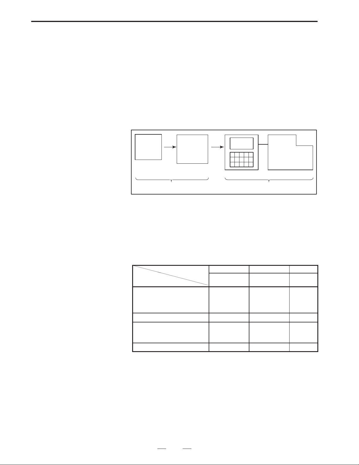
B–62754EN/01
Cutting rocess
GENERAL
1. GENERAL
1.1
GENERAL FLOW OF
OPERATION OF CNC
MACHINE TOOL
When machining the part using the CNC machine tool, first prepare the
program, then operate the CNC machine by using the program.
1) First, prepare the program from a part drawing to operate the CNC
machine tool.
How to prepare the program is described in the Chapter II.
PROGRAMMING.
2) The program is to be read into the CNC system. Then, mount the
workpieces and tools on the machine, and operate the tools according
to the programming. Finally, execute the machining actually.
How to operate the CNC system is described in the Chapter III.
OPERATION.
Part
drawing
CHAPTER II PROGRAMMING CHAPTER III OPERATION
Part
programming
CNC
MACHINE TOOL
Before the actual programming, make the machining plan for how to
machine the part.
Machining plan
1. Determination of workpieces machining range
2. Method of mounting workpieces on the machine tool
3. Machining sequence in every cutting process
4. Cutting tools and cutting conditions
Decide the cutting method in every cutting process.
in
Cutting procedure
1. Cutting method
: Rough
Semi
Finish
2. Cutting tools
3. Cutting conditions
: Feedrate
Cutting depth
4. Tool path
pr
1 2 3
End face
cutting
Outer diameter
cutting
Grooving
5
Page 28
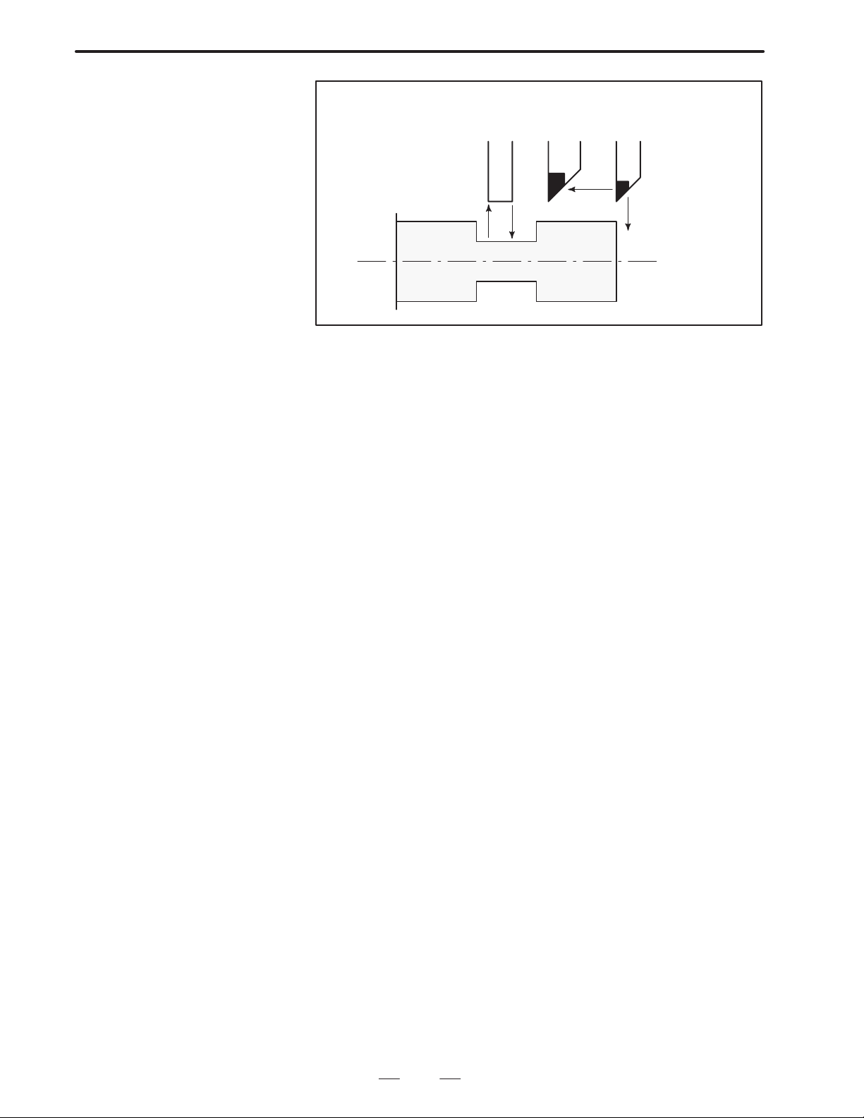
1. GENERAL
GENERAL
B–62754EN/01
Grooving
Outer
diameter
cutting
Workpiece
End
face
cutting
Prepare the program of the tool path and cutting condition according to
the workpiece figure, for each cutting.
6
Page 29

B–62754EN/01
1.2
NOTES ON READING THIS MANUAL
GENERAL
NOTE
1 The function of an CNC machine tool system depends not
only on the CNC, but on the combination of the machine
tool, its magnetic cabinet, the servo system, the CNC, the
operator’s panels, etc. It is too difficult to describe the
function, programming, and operation relating to all
combinations. This manual generally describes these from
the stand–point of the CNC. So, for details on a particular
CNC machine tool, refer to the manual issued by the
machine tool builder, which should take precedence over
this manual.
2 Headings are placed in the left margin so that the reader can
easily access necessary information. When locating the
necessary information, the reader can save time by
searching though these headings.
3 Machining programs, parameters, variables, etc. are stored
in the CNC unit internal non–volatile memory. In general,
these contents are not lost by the switching ON/OFF of the
power. However, it is possible that a state can occur where
precious data stored in the non–volatile memory has to be
deleted, because of deletions from a maloperation, or by a
failure restoration. In order to restore rapidly when this kind
of mishap occurs, it is recommended that you create a copy
of the various kinds of data beforehand.
4 This manual describes as many reasonable variations in
equipment usage as possible. It cannot address every
combination of features, options and commands that
should not be attempted.
If a particular combination of operations is not described, it
should not be attempted.
1. GENERAL
7
Page 30

II. PROGRAMMING
Page 31

B–62754EN/01
1
PROGRAMMING
1. GENERAL
11
Page 32
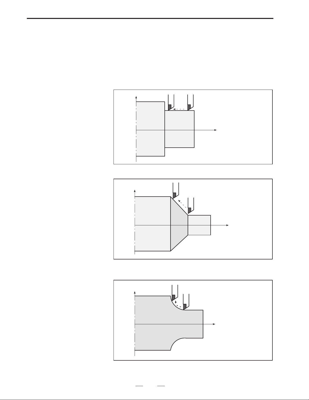
1. GENERAL
PROGRAMMING
B–62754EN/01
1.1
TOOL MOVEMENT
ALONG WORKPIECE
PARTS FIGURE–
INTERPOLATION
Explanations
D Tool movement along a
straight line
The tool moves along straight lines and arcs constituting the workpiece
parts figure (See II–4).
X
Tool
Workpiece
Fig.1.1 (a) T ool movement along the straight line which is parallel to Z–axis
Program
G01 Z...;
Z
D Tool movement along an
arc
X
Tool
Workpiece
Fig.1.1 (b) T ool movement along the taper line
X
Workpiece
Tool
Program
G02X ... Z ... R ... ;
or
G03X ... Z ... R ... ;
Z
Program
G01 X ... Z... ;
Z
Fig. 1.1 (c) T ool movement along an arc
12
Page 33
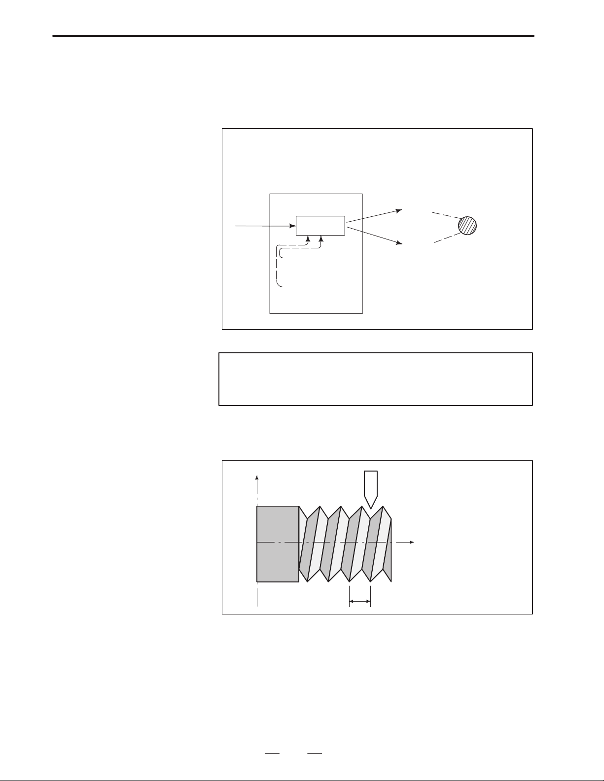
B–62754EN/01
PROGRAMMING
1. GENERAL
The term interpolation refers to an operation in which the tool moves
along a straight line or arc in the way described above.
Symbols of the programmed commands G01, G02, ... are called the
preparatory function and specify the type of interpolation conducted in
the control unit.
(a) Movement along straight line
G01 Z__;
X––Z––––;
Control unit
Interpolation
a) Movement
along straight
line
b) Movement
along arc
Fig. 1.1 (d) Interpolation function
(b) Movement along arc
G03X––Z––;
X axis
Y axis
Tool
movement
NOTE
Some machines move tables instead of tools but this
manual assumes that tools are moved against workpieces.
D Thread cutting
Threads can be cut by moving the tool in synchronization with spindle
rotation. In a program, specify the thread cutting function by G32.
X
Workpiece
Fig. 1.1 (e) Straight thread cutting
Tool
Z
F
Program
G32Z––F––;
13
Page 34
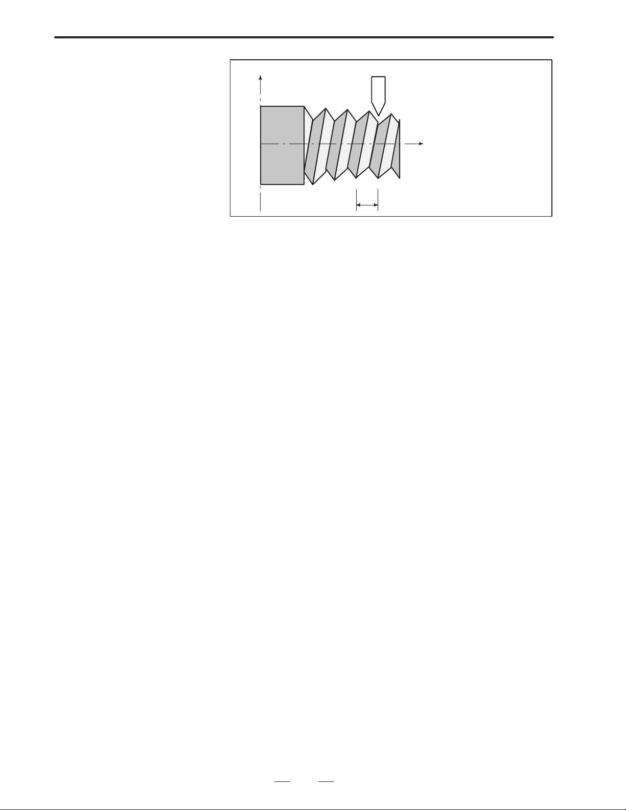
1. GENERAL
PROGRAMMING
B–62754EN/01
X
Workpiece
Tool
Program
G32X––Z––F––;
Z
F
Fig. 1.1 (f) Taper thread cutting
14
Page 35
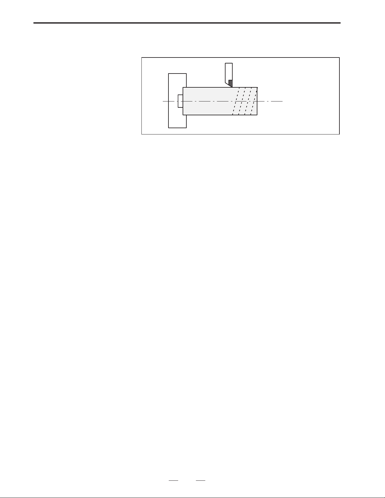
B–62754EN/01
PROGRAMMING
1. GENERAL
1.2
FEED–
FEED FUNCTION
Movement of the tool at a specified speed for cutting a workpiece is called
the feed.
Chuck
Workpiece
Fig. 1.2 (a) Feed function
Tool
Feedrates can be specified by using actual numerics.
For example, the following command can be used to feed the tool 2 mm
while the workpiece makes one turn :
F2.0
The function of deciding the feed rate is called the feed function (See
II–5).
15
Page 36
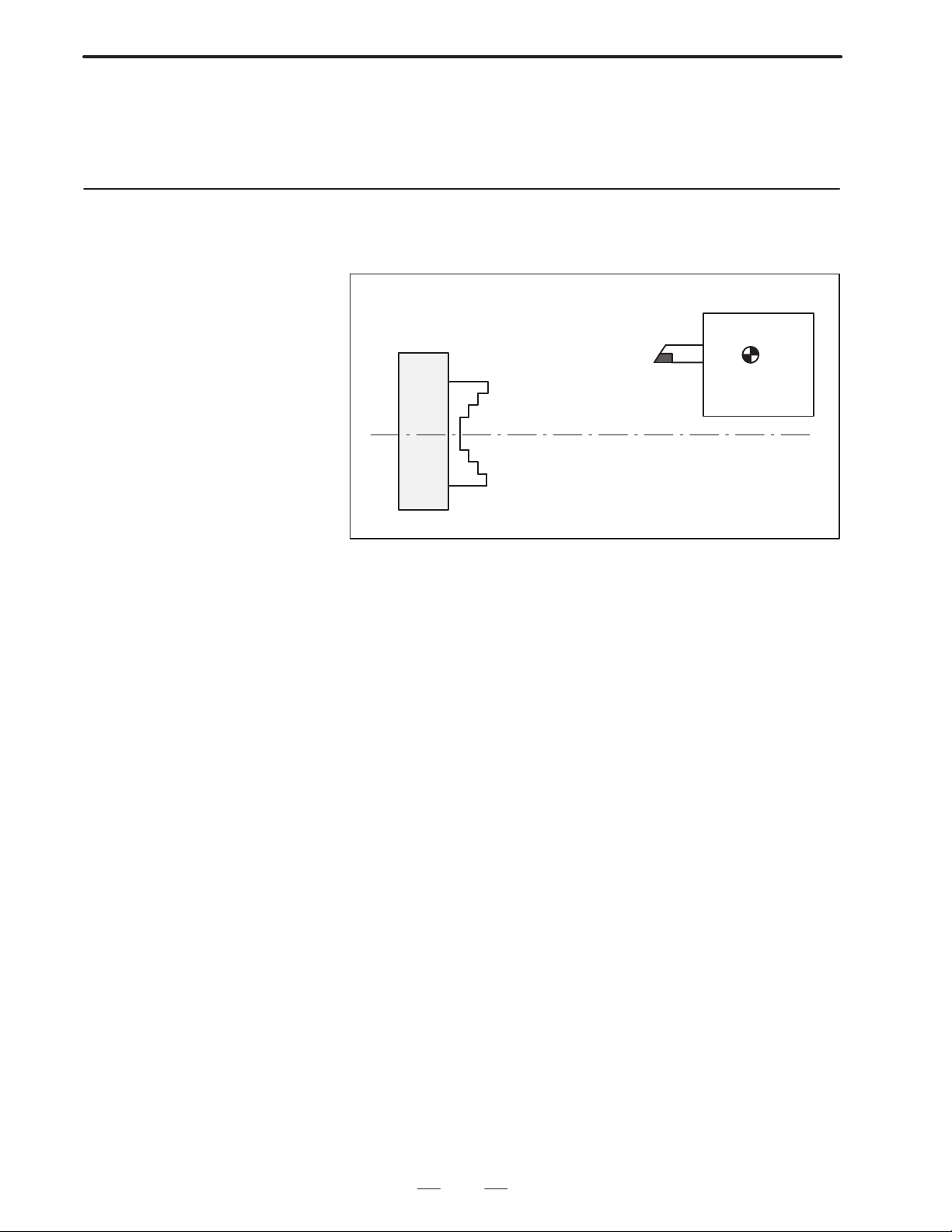
1. GENERAL
1.3
PART DRAWING AND TOOL MOVEMENT
PROGRAMMING
B–62754EN/01
1.3.1
Reference Position
(Machine–Specific
Position)
Explanations
A CNC machine tool is provided with a fixed position. Normally, tool
change and programming of absolute zero point as described later are
performed at this position. This position is called the reference position.
Tool post
Chuck
Fig. 1.3.1 (a) Reference position
The tool can be moved to the reference position in two ways:
1. Manual reference position return (See III–3.1)
Reference position return is performed by manual button operation.
Reference
position
2. Automatic reference position return (See II–6)
In general, manual reference position return is performed first after
the power is turned on. In order to move the tool to the reference
position for tool change thereafter, the function of automatic
reference position return is used.
16
Page 37
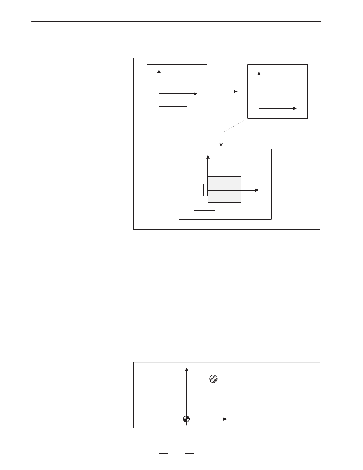
B–62754EN/01
1.3.2
Coordinate System on
Part Drawing and
Coordinate System
Specified by CNC –
Coordinate System
PROGRAMMING
X
Part drawing
1. GENERAL
X
Program
Z
Z
Coordinate system
CNC
Command
X
Workpiece
Explanations
D Coordinate system
Z
Machine tool
Fig. 1.3.2 (a) Coordinate system
The following two coordinate systems are specified at different locations:
(See II–8)
1. Coordinate system on part drawing
The coordinate system is written on the part drawing. As the program
data, the coordinate values on this coordinate system are used.
2. Coordinate system specified by the CNC
The coordinate system is prepared on the actual machine tool. This
can be achieved by programming the distance from the current
position of the tool to the zero point of the coordinate system to be
set.
X
230
300
Program
zero point
Fig. 1.3.2 (b) Coordinate system specified by the CNC
Present tool position
Distance to the zero point of a coordinate system to be set
Z
17
Page 38
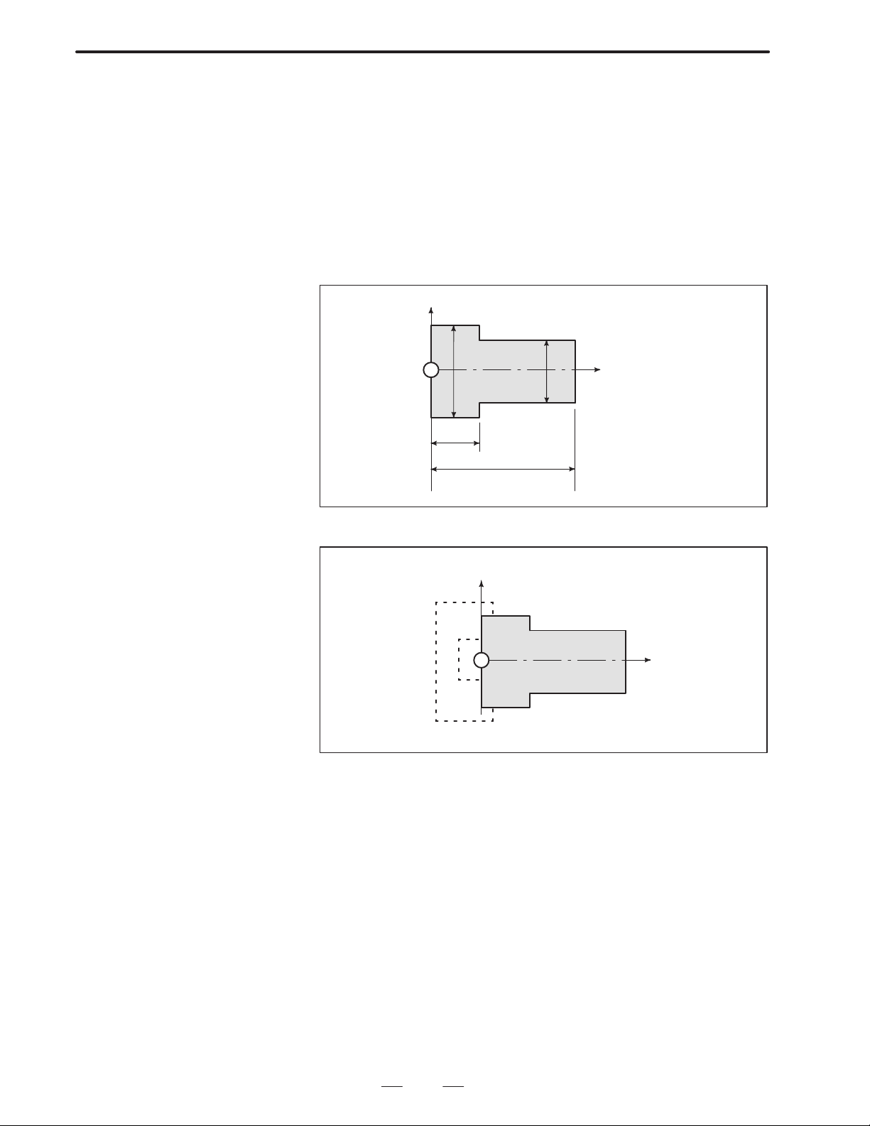
1. GENERAL
PROGRAMMING
B–62754EN/01
The tool moves on the coordinate system specified by the CNC in
accordance with the command program generated with respect to the
coordinate system on the part drawing, and cuts a workpiece into a shape
on the drawing.
Therefore, in order to correctly cut the workpiece as specified on the
drawing, the two coordinate systems must be set at the same position.
D Methods of setting the
two coordinate systems
in the same position
The following method is usually used to define two coordinate systems
at the same location.
1. When coordinate zero point is set at chuck face
X
Workpiece
60
40
150
Fig. 1.3.2 (c) Coordinates and dimensions on part drawing
X
40
Z
Workpiece
Z
Fig. 1.3.2 (d) Coordinate system on lathe as specified by CNC
(made to coincide with the coordinate system on part drawing)
18
Page 39

B–62754EN/01
PROGRAMMING
2. When coordinate zero point is set at work end face.
X
1. GENERAL
Workpiece
60
100
Fig. 1.3.2 (e) Coordinates and dimensions on part drawing
Workpiece
Fig. 1.3.2 (f) Coordinate system on lathe as specified by CNC
(made to coincide with the coordinate system on part drawing)
80
30
30
Z
X
Z
19
Page 40
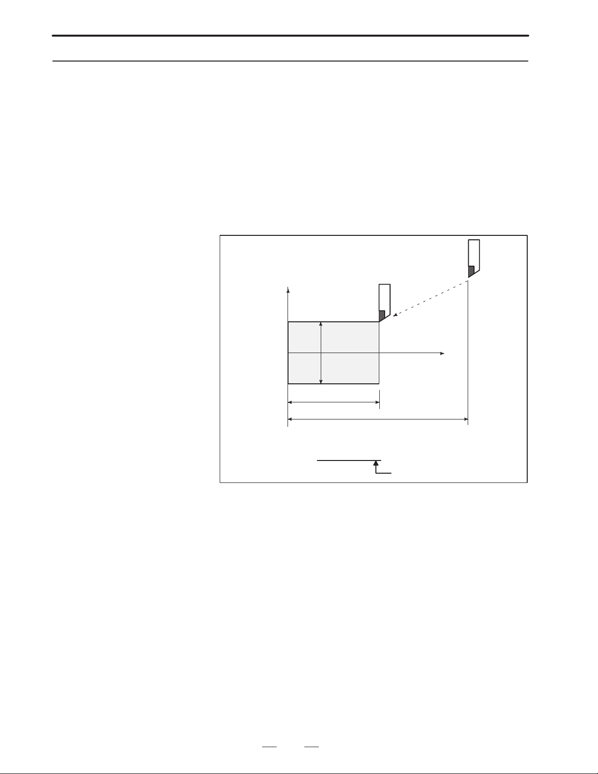
1. GENERAL
1.3.3
How to Indicate
Command Dimensions
for Moving the Tool –
Absolute, Incremental
Commands
PROGRAMMING
B–62754EN/01
Explanations
D Absolute command
Methods of command for moving the tool can be indicated by absolute
or incremental designation (See II–9.1).
The tool moves to a point at “the distance from zero point of the
coordinate system” that is to the position of the coordinate values.
Tool
X
Workpiece
φ30
70
Command specifying movement from point A to point B
G90X30.0Z70.0;
B
110
A
Z
Fig. 1.3.3 (a) Absolute command
20
Coordinates of point B
Page 41
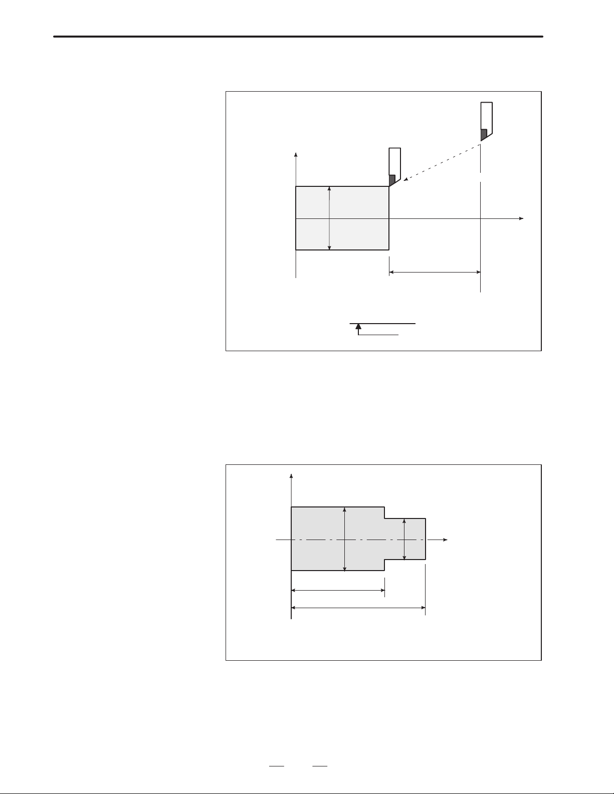
B–62754EN/01
PROGRAMMING
1. GENERAL
D Incremental command
Specify the distance from the previous tool position to the next tool
position.
Tool
A
X
φ60
B
Z
φ30
40
Command specifying movement from point A to point B
U–30.0W–40.0
Distance and direction for
movement along each axis
D Diameter programming /
radius programming
Fig. 1.3.3 (b) Incremental command
Dimensions of the X axis can be set in diameter or in radius. Diameter
programming or radius programming is employed independently in each
machine.
1. Diameter programming
In diameter programming, specify the diameter value indicated on the
drawing as the value of the X axis.
X
B
φ30
A
Z
Workpiece
φ40
60
80
Coordinate values of points A and B
A(30.0, 80.0), B(40.0, 60.0)
Fig. 1.3.3 (c) Diameter programming
21
Page 42

1. GENERAL
PROGRAMMING
B–62754EN/01
2. Radius programming
In radius programming, specify the distance from the center of the
workpiece, i.e. the radius value as the value of the X axis.
X
B
20
Workpiece
60
80
Coordinate values of points A and B
A(15.0, 80.0), B(20.0, 60.0)
Fig. 1.3.3 (d) Radius programming
A
15
Z
22
Page 43

B–62754EN/01
PROGRAMMING
1. GENERAL
1.4
CUTTING SPEED –
SPINDLE SPEED
FUNCTION
Examples
The speed of the tool with respect to the workpiece when the workpiece
is cut is called the cutting speed.
As for the CNC, the cutting speed can be specified by the spindle speed
in rpm unit.
Tool
Workpiece
Fig. 1.4 (a) Cutting speed
V: Cutting speed
v m/min
φ
N rpm
<When a workpiece 200 mm in diameter should be machined at
a cutting speed of 300 m/min. >
The spindle speed is approximately 478 rpm, which is obtained from
N=1000v/πD. Hence the following command is required:
S478 ;
Commands related to the spindle speed are called the spindle speed
function (See II–10).
The cutting speed v (m/min) can also be specified directly by the speed
value. Even when the workpiece diameter is changed, the CNC changes
the spindle speed so that the cutting speed remains constant.
This function is called the constant surface speed control function
(See II–10.2).
23
Page 44

1. GENERAL
PROGRAMMING
B–62754EN/01
1.5
SELECTION OF TOOL
USED FOR VARIOUS
MACHINING – TOOL
FUNCTION
Examples
When drilling, tapping, boring, milling or the like, is performed, it is
necessary to select a suitable tool. When a number is assigned to each tool
and the number is specified in the program, the corresponding tool is
selected.
Tool number
01
06
02
03
Fig. 1.5 (a) T ool used for various machining
05
04
Tool post
<When No.01 is assigned to a roughing tool>
When the tool is stored at location 01 of the tool post, the tool can be
selected by specifying T0101.
This is called the tool function (See II–11).
24
Page 45

B–62754EN/01
PROGRAMMING
1. GENERAL
1.6
COMMAND FOR
MACHINE
OPERATIONS –
MISCELLANEOUS
FUNCTION
When machining is actually started, it is necessary to rotate the spindle,
and feed coolant. For this purpose, on–off operations of spindle motor and
coolant valve should be controlled (See II–12).
Coolant on/off
Chuck open/close
Workpiece
Fig. 1.6 (a) Command for machine operations
The function of specifying the on–off operations of the components of the
machine is called the miscellaneous function. In general, the function is
specified by an M code.
For example, when M03 is specified, the spindle is rotated clockwise at
the specified spindle speed.
CW spindle rotation
25
Page 46

1. GENERAL
PROGRAMMING
B–62754EN/01
1.7
PROGRAM CONFIGURATION
A group of commands given to the CNC for operating the machine is
called the program. By specifying the commands, the tool is moved along
a straight line or an arc, or the spindle motor is turned on and off.
In the program, specify the commands in the sequence of actual tool
movements.
Block
Block
Tool movement sequence
Block
Program
Block
⋅
⋅
⋅
⋅
Block
Fig. 1.7 (a) Program configuration
A group of commands at each step of the sequence is called the block.
The program consists of a group of blocks for a series of machining. The
number for discriminating each block is called the sequence number, and
the number for discriminating each program is called the program
number (See II–13).
26
Page 47

B–62754EN/01
PROGRAMMING
1. GENERAL
Explanations
D Block
D Program
The block and the program have the following configurations.
1 block
N fffff G ff Xff.f Zfff.f M ff S ff T ff ;
Sequence
number
Preparatory
function
Dimension word Miscel-
laneous
function
Fig. 1.7 (b) Block configuration
Spindle
function
Tool
function
End of
block
A block begins with a sequence number that identifies that block and ends
with an end–of–block code.
This manual indicates the end–of–block code by ; (LF in the ISO code and
CR in the EIA code).
;
Offff;
⋅
⋅
⋅
M30 ;
Fig. 1.7 (c) Program configuration
Program number
Bloc
k
Bloc
k
⋅
Bloc
⋅
k
⋅
End of program
Normally , a program number is specified after the end–of–block (;) code
at the beginning of the program, and a program end code (M02 or M30)
is specified at the end of the program.
27
Page 48

1. GENERAL
PROGRAMMING
B–62754EN/01
D Main program and
subprogram
When machining of the same pattern appears at many portions of a
program, a program for the pattern is created. This is called the
subprogram. On the other hand, the original program is called the main
program. When a subprogram execution command appears during
execution of the main program, commands of the subprogram are
executed. When execution of the subprogram is finished, the sequence
returns to the main program.
Main program
⋅
⋅
M98P1001
⋅
⋅
⋅
M98P1002
⋅
⋅
⋅
M98P1001
⋅
⋅
Subprogram #1
O1001
M99
Subprogram #2
O1002
Program for
hole #1
Program for
hole #2
⋅
M99
28
Page 49
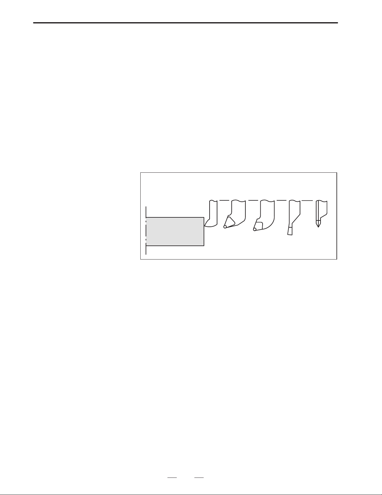
B–62754EN/01
1.8
TOOL FIGURE AND TOOL MOTION BY PROGRAM
Explanations
PROGRAMMING
1. GENERAL
D Machining using the end
of cutter – Tool length
compensation function
(See II–15.1)
Usually, several tools are used for machining one workpiece. The tools
have different tool length. It is very troublesome to change the program
in accordance with the tools.
Therefore, the length of each tool used should be measured in advance.
By setting the difference between the length of the standard tool and the
length of each tool in the CNC (data display and setting : see III–11),
machining can be performed without altering the program even when the
tool is changed. This function is called tool length compensation.
Workpiece
Standard
tool
Rough
cutting
tool
Fig. 1.8 (a) T ool offset
Finishing
tool
Grooving
tool
Thread
cutting
tool
29
Page 50
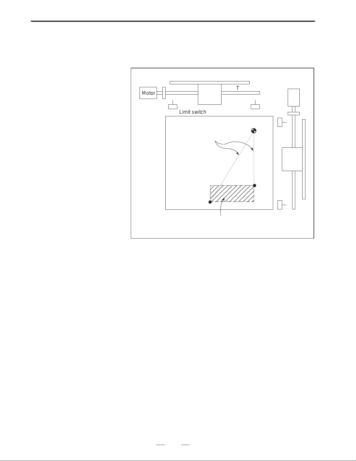
1. GENERAL
PROGRAMMING
B–62754EN/01
1.9
TOOL MOVEMENT
RANGE – STROKE
Limit switches are installed at the ends of each axis on the machine to
prevent tools from moving beyond the ends. The range in which tools can
move is called the stroke. Besides the stroke limits, data in memory can
be used to define an area which tools cannot enter.
Table
Motor
Limit switch
Machine zero point
Specify these distances.
Tools cannot enter this area. The area is specified by data in memory or
a program.
Besides strokes defined with limit switches, the operator can define an
area which the tool cannot enter using a program or data in memory (see
Section III–11). This function is called stroke check.
30
Page 51

B–62754EN/01
2
PROGRAMMING
CONTROLLED AXES
2. CONTROLLED AXES
31
Page 52
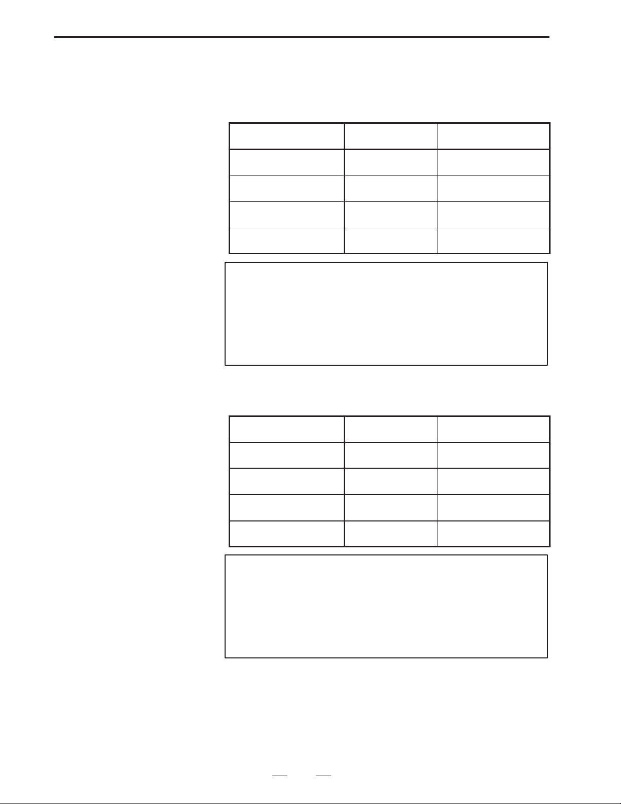
2. CONTROLLED AXES
2.1
CONTROLLED AXES
Series 16
Series 160
PROGRAMMING
Item
Number of basic
controlled axes
Controlled axis expansion
(total)
Number of basic simultaneously controlled axes
Simultaneously controlled
axis expansion (total)
16–TC
160–TC
2 axes 2 axes for each tool post
Max. 8 axes
(Included in Cs axis)
2 axes 2 axes for each tool post
Max. 6 axes Max. 4 axes for each tool
(two–path control)
(4 axes in total)
Max. 6 axes for each tool
post +Cs axis (Note)
(4 axes in total)
post
B–62754EN/01
16–TC, 160–TC
NOTE
1 A two–path control system with a 9–inch CRT has up to
eight controlled axes.
2 The number of simultaneously controllable axes for manual
operation (jog feed, incremental feed, or manual handle
feed) is 1 or 3 (1 when bit 0 (JAX) of parameter 1002 is set
to 0 and 3 when it is set to 1).
Series 18
Series 180
Item
Number of basic
controlled axes
Controlled axis expansion
(total)
Number of basic simultaneously controlled axes
Simultaneously controlled
axis expansion (total)
18–TC
180–TC
2 axes 2 axes for each tool post
Max. 6 axes
(Included in Cs axis)
2 axes 2 axes for each tool post
Max. 4 axes Max. 4 axes for each tool
18–TC, 180–TC
(two–path control)
(4 axes in total)
Max. 4 axes for each tool
post +Cs axis (Note)
(4 axes in total)
post
NOTE
1 A two–path control system with a 9–inch CRT has up to
eight controlled axes.
2 The number of simultaneously controllable axes for manual
operation (jog feed, incremental feed, or manual handle
feed) is 1 or 3 (1 when bit 0 (JAX) of parameter 1002 is set
to 0 and 3 when it is set to 1).
32
Page 53

B–62754EN/01
PROGRAMMING
2. CONTROLLED AXES
2.2
NAMES OF AXES
Limitations
D Default axis name
D Duplicate axis name
The names of two basic axes are always X and Z; the names of additional
axes can be optionally selected from A, B, C, U, V, W, and Y by using
parameter No.1020.
Each axis name is determined according to parameter No. 1020. If the
parameter specifies 0 or anything other than the nine letters, the axis name
defaults to a number from 1 to 8.
With two–path control, the names of two basic axes for one tool post are
always X and Z; the names of additional axes can be optionally selected
from A, B, C, U, V, W, and Y by using parameter No. 1020. For one tool
post, the same axis name cannot be assigned to multiple axes, but the same
axis name can be used
with the other tool post.
When a default axis name (1 to 8) is used, the system cannot operate in
MEM or MDI mode.
If the parameter specifies an axis name more than once, only the first axis
to be assigned that axis name becomes operable.
NOTE
1 When G code system A is used, the letters U, V, and W
cannot be used as an axis name (hence, the maximum of
six controlled axes), because these letters are used as
incremental commands for X, Y, and Z. To use the letters
U, V, and W as axis names, the G code system must be B
or C. Likewise, letter H is used as an incremental command
for C, thus incremental commands cannot be used if A or B
is used as an axis name.
2 With two–path control, when information (such as the
current position) about each axis is displayed on the CRT
screen, an axis name may be followed by a subscript to
indicate a tool post number (e.g.,X1 and X2). This is axis
name to help the user to easily understand which tool post
an axis belongs to. When writing a program, the user must
specify X, Y, Z, U, V, W, A, B, and C without attaching a
subscript.
3 In G76 (multiple–thread cutting), the A address in a block
specifies the tool nose angle instead of a command for axis
A.
If C or A is used as an axis name, C or A cannot be used as
an angle command for a straight line in chamfering or direct
drawing dimension programming. Therefore, C and A
should be used according to bit 4 (CCR) of parameter No.
3405.
33
Page 54
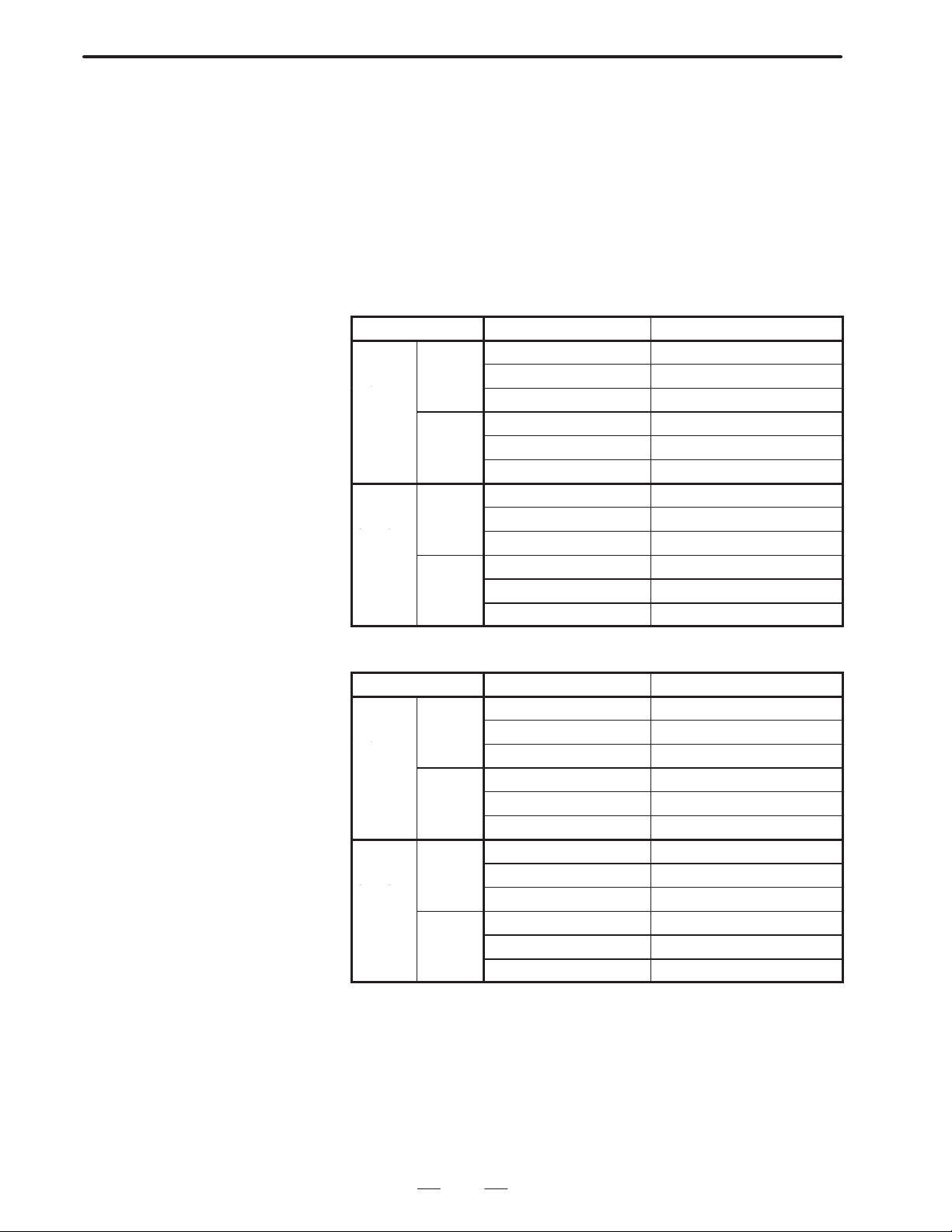
2. CONTROLLED AXES
i
t
a
i
t
i
t
ce
i
t
i
t
a
i
t
i
t
ce
i
t
PROGRAMMING
B–62754EN/01
2.3
INCREMENT SYSTEM
The increment system consists of the least input increment (for input ) and
least command increment (for output). The least input increment is the
least increment for programming the travel distance. The least command
increment is the least increment for moving the tool on the machine. Both
increments are represented in mm, inches, or degrees.
The increment system is classified into IS–B and IS–C (T ables 2.3(a) and
2.3(b)). Select IS–B or IS–C using bit 1 (ISC) of parameter 1004. When
the IS–C increment system is selected, it is applied to all axes and the 1/10
increment system option is required.
T able 2.3 (a) Increment system IS–B
Least input increment Least command increment
Metric
system
machine
Inch
machine
system
mm
npu
inch
npu
mm
npu
inch
npu
0.001mm(Diameter) 0.0005mm
0.001mm(Radius) 0.001mm
0.001deg 0.001deg
0.0001inch(Diameter) 0.0005mm
0.0001inch(Radius) 0.001mm
0.001deg 0.001deg
0.001mm(Diameter) 0.00005inch
0.001mm(Radius) 0.0001inch
0.001deg 0.001deg
0.0001inch(Diameter) 0.00005inch
0.0001inch(Radius) 0.0001inch
0.001deg 0.001deg
Metric
system
machine
Inch
machine
system
T able 2.3 (b) Increment system IS–C
Least input increment Least command increment
mm
npu
inch
npu
mm
npu
inch
npu
0.0001mm(Diameter) 0.00005mm
0.0001mm(Radius) 0.0001mm
0.0001deg 0.0001deg
0.00001inch(Diameter) 0.00005mm
0.00001inch(Radius) 0.0001mm
0.0001deg 0.0001deg
0.0001mm(Diameter) 0.000005inch
0.0001mm(Radius) 0.00001inch
0.0001deg 0.0001deg
0.00001inch(Diameter) 0.000005inch
0.00001inch(Radius) 0.00001inch
0.0001deg 0.0001deg
34
Page 55

B–62754EN/01
IS–B
IS–C
PROGRAMMING
2. CONTROLLED AXES
2.4
MAXIMUM STROKES
The maximum stroke controlled by this CNC is shown in the table below:
Maximum stroke=Least command increment99999999
T able 2.4 (a) Maximum strokes
Increment system
Metric machine
system
–
Inch machine
system
Metric machine
system
–
Inch machine
system
Maximum strokes
99999.999 mm
99999.999 deg
9999.9999 inch
99999.999 deg
9999.9999 mm
9999.9999 deg
999.99999 inch
9999.9999 deg
NOTE
1 The unit in the table is a diameter value with diameter
programming and a radius value in radius programming.
2 A command exceeding the maximum stroke cannot be
specified.
3 The actual stroke depends on the machine tool.
35
Page 56
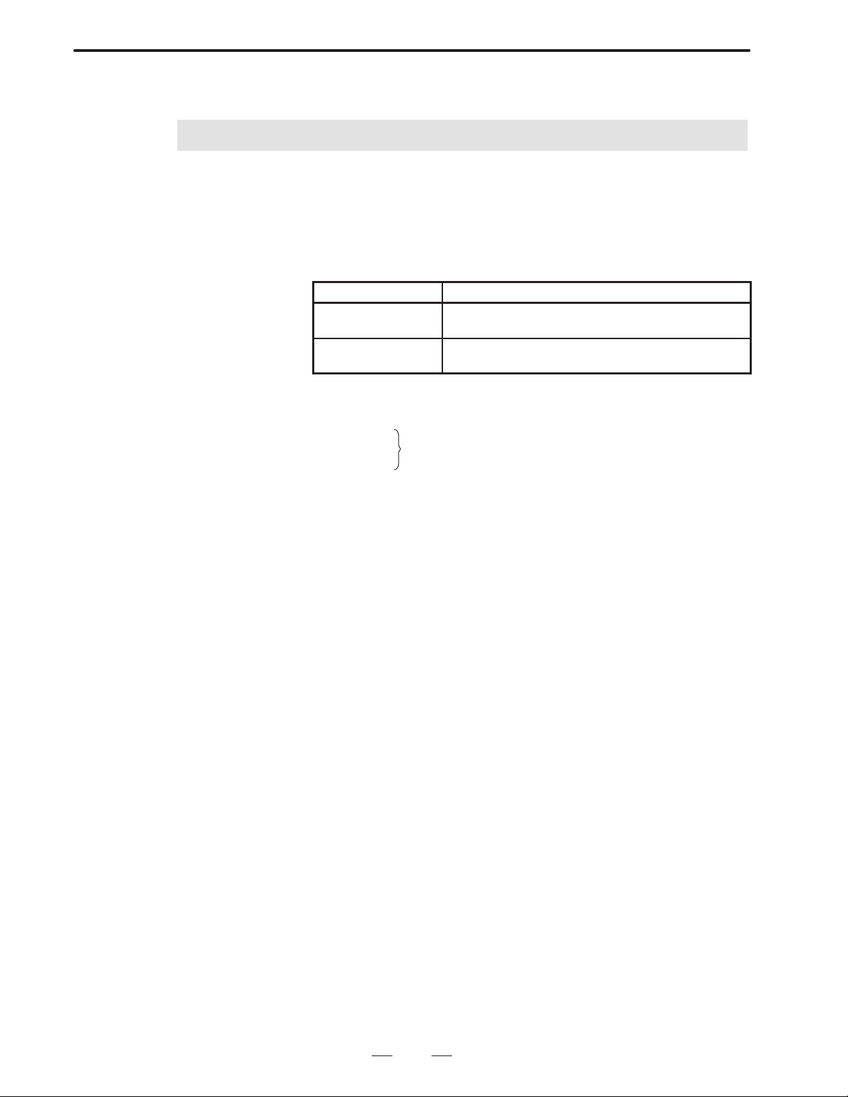
3. PREPARATORY FUNCTION
(G FUNCTION)
PREPARATORY FUNCTION (G FUNCTION )
3
PROGRAMMING
A number following address G determines the meaning of the command
for the concerned block.
G codes are divided into the following two types.
Type Meaning
One–shot G code The G code is effective only in the block in which it is
specified
Modal G code The G code is effective until another G code of the
same group is specified.
(Example)
G01 and G00 are modal G codes.
B–62754EN/01
G01X_;
Z_;
X_;
G00Z_;
There are three G code systems : A,B, and C (Table 3). Select a G code
system using bits 6 (GSB) and 7 (GSC) of parameter 3401. Generally , this
manual describes the use of G code system A, except when the described
item can use only G code system B or C. ln such cases, the use of G code
system B or C is described.
G01 is effective in this range
36
Page 57

B–62754EN/01
PROGRAMMING
3. PREP ARATORY FUNCTION
(G FUNCTION)
Explanations
1. If the CNC enters the clear state (see bit 6 (CLR) of parameter 3402)
when the power is turned on or the CNC is reset, the modal G codes
change as follows.
(1)G codes marked with
in Table 3 are enabled.
(2)When the system is cleared due to power–on or reset, whichever
specified, either G20 or G21, remains effective.
(3)Bit 7 of parameter No. 3402 can be used to specify whether G22
or G23 is selected upon power–on. Resetting the CNC to the clear
state does not affect the selection of G22 or G23.
(4) Setting bit 0 (G01) of parameter 3402 determines which code,
either G00 or G01, is effective.
(5) Setting bit 3 (G91) of parameter 3402 determines which code,
either G90 or G91, is effective.
2. G codes of group 00 except G10 and G11 are single–shot G codes.
3. P/S larm (No.010) is displayed when a G code not listed in the G code
list is specified or a G code without a corresponding option is
specified.
4. G codes of different groups can be specified in the same block.
If G codes of the same group are specified in the same block, the G
code specified last is valid.
5. If a G code of group 01 is specified in a canned cycle, the canned cycle
is canceled in the same way as when a G80 command is specified. G
codes of group 01 are not affected by G codes for specifying a canned
cycle.
6. When G code system A is used for a canned cycle, only the initial level
is provided at the return point.
7. G codes are displayed for each group number.
37
Page 58

3. PREPARATORY FUNCTION
Grou
Function
01
06
09
08
01
00
(G FUNCTION)
G code
A B C
G00 G00 G00
G01 G01 G01
G02 G02 G02
G03 G03 G03 Circular interpolation CCW or Helical interpolation CCW
G04 G04 G04 Dwell
G05 G05 G05 High speed cycle cutting
G07.1
(G107)
G10
G10.6 G10.6 G10.6 Tool retract & recover
G11 G11 G11 Programmable data input cancel
G12.1
(G112)
G13.1
(G113)
G17 G17 G17
G18 G18 G18
G19 G19 G19 Y pZp plane selection
G20 G20 G70
G21 G21 G71
G22 G22 G22
G23 G23 G23
G25 G25 G25
G26 G26 G26
G27 G27 G27 Reference position return check
G28 G28 G28 Return to reference position
G30 G30 G30 00 2nd, 3rd and 4th reference position return
G30.1 G30.1 G30.1 Floating reference point return
G31 G31 G31 Skip function
G32 G33 G33
G34 G34 G34
G36 G36 G36 Automatic tool compensation X
G37 G37 G37 00 Automatic tool compensation Z
G39 G39 G39 Corner circular interpolation
G40 G40 G40
G41 G41 G41
G42 G42 G42 Tool nose radius compensation right
G50 G92 G92
G50.3 G92.1 G92.1
G07.1
(G107)
G10 G10
G12.1
(G112)
G13.1
(G113)
G07.1
(G107)
G12.1
(G112)
G13.1
(G113)
PROGRAMMING
Table 3 G code list (1/3)
p
00
21
16
07
B–62754EN/01
Positioning (Rapid traverse)
Linear interpolation (Cutting feed)
Circular interpolation CW or Helical interpolation CW
Cylindrical interpolation
Programmable data input
Polar coordinate interpolation mode
Polar coordinate interpolation cancel mode
XpY p plane selection
ZpXp plane selection
Input in inch
Input in mm
Stored stroke check function on
Stored stroke check function off
Spindle speed fluctuation detection off
Spindle speed fluctuation detection on
Thread cutting
V ariable–lead thread cutting
Tool nose radius compensation cancel
Tool nose radius compensation left
Coordinate system setting or max. spindle speed setting
Workpiece coordinate system preset
38
Page 59

B–62754EN/01
Grou
Function
20
00
14
12
04
00
10
02
A B C
G50.2
(G250)
G51.2
(G251)
G52 G52 G52
G53 G53 G53
G54 G54 G54
G55 G55 G55
G56 G56 G56
G57 G57 G57
G58 G58 G58 Workpiece coordinate system 5 selection
G59 G59 G59 Workpiece coordinate system 6 selection
G65 G65 G65 00 Macro calling
G66 G66 G66
G67 G67 G67
G68 G68 G68
G69 G69 G69
G70 G70 G72 Finishing cycle
G71 G71 G73
G72 G72 G74
G73 G73 G75 Pattern repeating
G74 G74 G76 End face peck drilling
G75 G75 G77 Outer diameter/internal diameter drilling
G76 G76 G78 Multiple threading cycle
G71 G71 G72 Traverse grinding cycle (for grinding machine)
G72 G72 G73
G73 G73 G74 Oscilation grinding cycle (for grinding machine)
G74 G74 G75
G80 G80 G80
G83 G83 G83 Cycle for face drilling
G84 G84 G84
G86 G86 G86
G87 G87 G87 Cycle for side drilling
G88 G88 G88 Cycle for side tapping
G89 G89 G89 Cycle for side boring
G90 G77 G20 Outer diameter/internal diameter cutting cycle
G92 G78 G21 01 Thread cutting cycle
G94 G79 G24 Endface turning cycle
G96 G96 G96
G97 G97 G97
G code
G50.2
(G250)
G51.2
(G251)
G50.2
(G250)
G51.2
(G251)
PROGRAMMING
Table 3 G code list (2/3)
p
Polygonal turning cancel
Polygonal turning
Local coordinate system setting
Machine coordinate system setting
Workpiece coordinate system 1 selection
Workpiece coordinate system 2 selection
14
01
Workpiece coordinate system 3 selection
Workpiece coordinate system 4 selection
Macro modal call
Macro modal call cancel
Mirror image for double turrets ON or balance cut mode
Mirror image for double turrets OFF or balance cut mode cancel
Stock removal in turning
Stock removal in facing
Traverse direct constant–dimension grinding cycle
(for grinding machine)
Oscilation direct constant–dimension grinding cycle
(for grinding machine)
Canned cycle for drilling cancel
Cycle for face tapping
Cycle for face boring
Constant surface speed control
Constant surface speed control cancel
3. PREP ARATORY FUNCTION
(G FUNCTION)
39
Page 60

3. PREPARATORY FUNCTION
Grou
Function
05
03
11
(G FUNCTION)
G code
A B C
G98 G94 G94
G99
G91 G91
G98 G98
G99 G99
G95 G95
G90 G90
PROGRAMMING
Table 3 G code list (3/3)
p
Per minute feed
Per revolution feed
Absolute programming
Incremental programming
Return to initial level (See Explanations 6)
Return to R point level (See Explanations 6)
B–62754EN/01
40
Page 61

B–62754EN/01
4
PROGRAMMING
INTERPOLATION FUNCTIONS
4. INTERPOLA TION FUNCTIONS
41
Page 62

4. INTERPOLA TION FUNCTIONS
PROGRAMMING
B–62754EN/01
4.1
POSITIONING (G00)
Format
Explanations
The G00 command moves a tool to the position in the workpiece system
specified with an absolute or an incremental command at a rapid traverse
rate.
In the absolute command, coordinate value of the end point is
programmed.
In the incremental command the distance the tool moves is programmed.
G00IP_;
_: For an absolute command, the coordinates of an end
position, and for an incremental command, the distance
the tool moves.
Either of the following tool paths can be selected according to bit 1 (LRP)
of parameter No. 1401.
D Nonlinear interpolation positioning
The tool is positioned with the rapid traverse rate for each axis
separately. The tool path is normally straight.
D Linear interpolation positioning
The tool path is the same as in linear interpolation (G01). The tool is
positioned within the shortest possible time at a speed that is not more
than the rapid traverse rate for each axis.
Linear interpolation positioning
End position
Non linear interpolation positioning
Start position
The rapid traverse rate in the G00 command is set to the parameter
No.1420 for each axis independently by the machine tool builder. In the
positioning mode actuated by G00, the tool is accelerated to a
predetermined speed at the start of a block and is decelerated at the end
of a block. Execution proceeds to the next block after confirming the
in–position.
“In–position” means that the feed motor is within the specified range.
This range is determined by the machine tool builder by setting to
parameter No.1826.
42
Page 63

B–62754EN/01
Examples
PROGRAMMING
X
56.0
4. INTERPOLA TION FUNCTIONS
30.5
30.0
Restrictions
φ40.0
Z
< Radius programming >
G00X40.0Z56.0 ; (Absolute command)
or
G00U–60.0W–30.5;(Incremental command)
The rapid traverse rate cannot be specified in the address F.
Even if linear interpolation positioning is specified, nonlinear
interpolation positioning is used in the following cases. Therefore, be
careful to ensure that the tool does not foul the workpiece.
D G28 specifying positioning between the reference and intermediate
positions.
D G53
43
Page 64

4. INTERPOLA TION FUNCTIONS
PROGRAMMING
B–62754EN/01
4.2
LINEAR
INTERPOLATION
(G01)
Format
Explanations
Tools can move along a line.
G01 _F_;
_: For an absolute command, the coordinates of an end
point , and for an incremental command, the distance
the tool moves.
F_: Speed of tool feed (Feedrate)
A tools move along a line to the specified position at the feedrate
specified in F.
The feedrate specified in F is effective until a new value is specified. It
need not be specified for each block.
The feedrate commanded by the F code is measured along the tool path.
If the F code is not commanded, the feedrate is regarded as zero.
For feed–per–minute mode under 2–axis simultaneous control, the
feedrate for a movement along each axis as follows :
Examples
D Linear interpolation
G01ααββ
< Diameter programming >
G01X40.0Z20.1F20 ; (Absolute command)
or
G01U20.0W–25.9F20 ; (Incremental command)
Ff ;
Feed rate of α axis direction :
Feed rate of β axis direction :
Ǹ
L +
2
) 2) 2)
2
X
20.1
F +
F
+
46.0
L
L
f
f
44
φ40.0
End point
Start point
φ20.0
Z
Page 65
B–62754EN/01
PROGRAMMING
4. INTERPOLA TION FUNCTIONS
4.3
CIRCULAR
INTERPOLATION
(G02, G03)
Format
The command below will move a tool along a circular arc.
Arc in the XpYp plane
G17
G02
G03
Arc in the ZpXp plane
G18
Arc in the YpZp plane
G19
G02
G03
G02
G03
Xp_Yp_
Xp_Zp_
Yp_Zp_
I_J_
R_
I_K_
R_
J_K_
R_
F_
F_
F_
Table.4.3 Description of the Command Format
Command Description
G17 Specification of arc on XpYp plane
G18 Specification of arc on ZpXp plane
G19 Specification of arc on YpZp plane
G02 Circular Interpolation Clockwise direction (CW)
G03 Circular Interpolation Counterclockwise direction (CCW)
X
p_
Y
p_
Z
p_
I_ Xp axis distance from the start point to the center of an arc with
J_ Yp axis distance from the start point to the center of an arc with
Command values of X axis or its parallel axis
(set by parameter No. 1022)
Command values of Y axis or its parallel axis
(set by parameter No. 1022)
Command values of Z axis or its parallel axis
(set by parameter No. 1022)
sign, radius value
sign, radius value
k_ Zp axis distance from the start point to the center of an arc with
sign, radius value
R_ Arc radius with no sign (always with radius value)
F_ Feedrate along the arc
45
Page 66
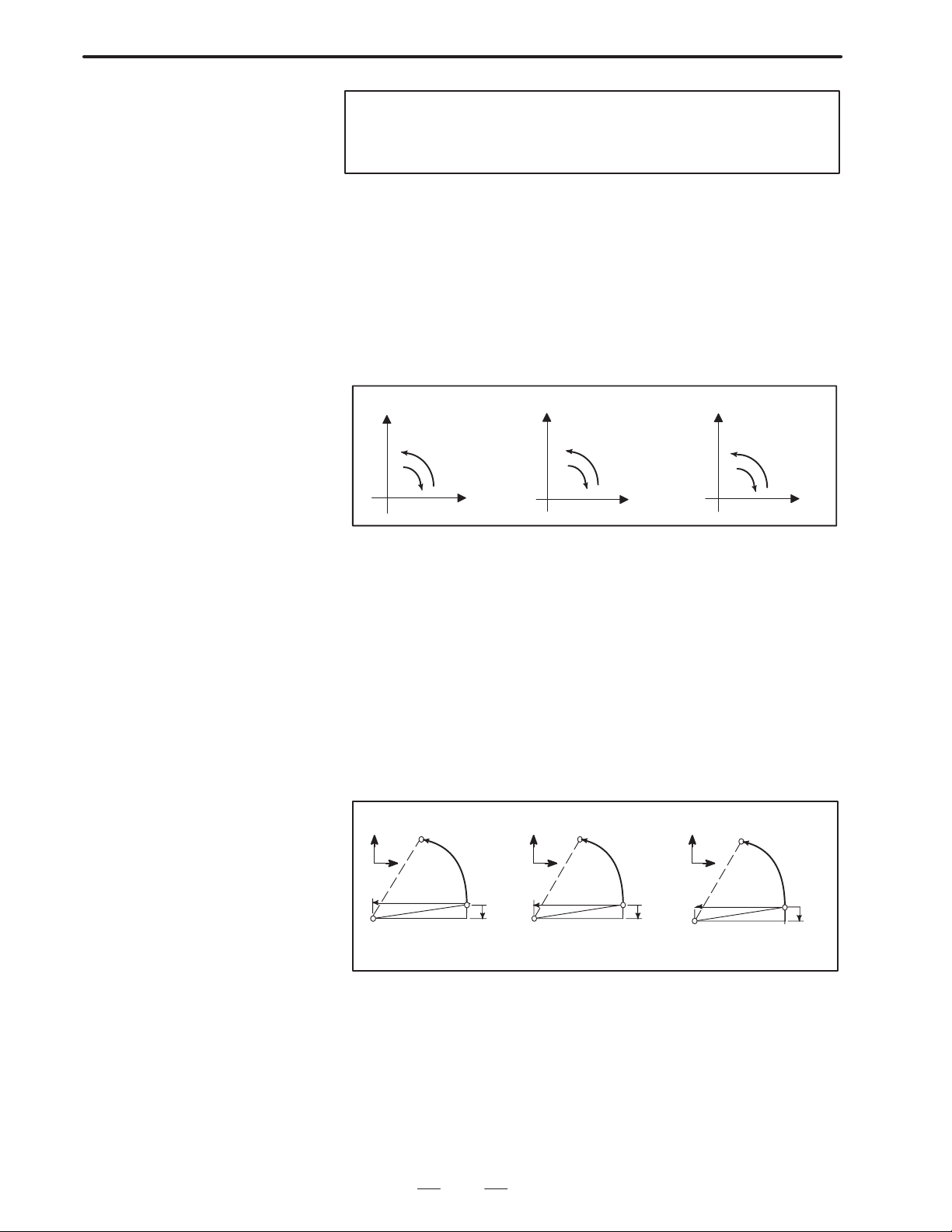
4. INTERPOLA TION FUNCTIONS
Explanations
PROGRAMMING
B–62754EN/01
NOTE
The U–, V–, and W–axes (parallel with the basic axis) can
be used with G–codes B and C.
D Direction of the circular
interpolation
D Distance moved on an
arc
D Distance from the start
point to the center of arc
“Clockwise”(G02) and “counterclockwise”(G03) on the X
(Z
plane or YpZp plane) are defined when the XpYp plane is viewed
pXp
in the positive–to–negative direction of the Z
axis (Yp axis or Xp axis,
p
pYp
plane
respectively) in the Cartesian coordinate system. See the figure below.
Yp
G02
G17
G03
Xp
Xp
G03
G02
Zp
G18
Zp
G02
G19
G03
Yp
The end point of an arc is specified by address Xp, Yp or Zp, and is
expressed as an absolute or incremental value according to G90 or G91.
For the incremental value, the distance of the end point which is viewed
from the start point of the arc is specified.
The arc center is specified by addresses I, J, and K for the Xp, Y p, and Zp
axes, respectively . The numerical value following I, J, or K, however, is
a vector component in which the arc center is seen from the start point,
and is always specified as an incremental value irrespective of G90 and
G91, as shown below.
I, J, and K must be signed according to the direction.
D Full–circle programming
End point (x,y)
yx
x
Center
i
Start
point
j
End point (z,x)
z
k
Center
Start
point
End point (y ,z)
z
y
i
Center
j
Start
point
k
I0,J0, and K0 can be omitted.
If the difference between the radius at the start point and that at the
end point exceeds the value in a parameter (No.3410), an P/S alarm
(No.020) occurs.
When X
p, Yp
, and Z
are omitted (the end point is the same as the start
p
point) and the center is specified with I, J, and K, a 360° arc (circle) is
specified.
46
Page 67
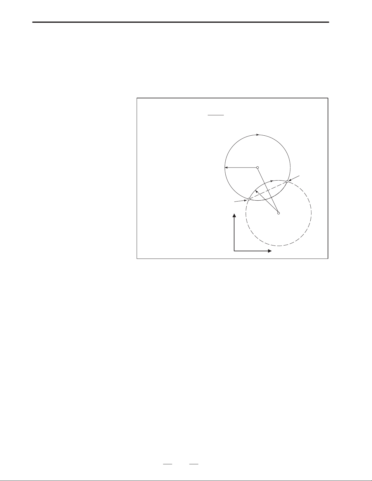
B–62754EN/01
PROGRAMMING
4. INTERPOLA TION FUNCTIONS
D
The distance between an arc and the center of a circle that contains the arc
can be specified using the radius, R, of the circle instead of I, J, and K.
In this case, one arc is less than 180
considered. An arc with a sector angle of 180
°, and the other is more than 180° are
°or wider cannot be
specified. If Xp, Yp, and Zp are all omitted, if the end point is located at
the same position as the start point and when R is used, an arc of 0
°is
programmed
G02R ; (The cutter does not move.)
For arc (1) (less than 180°)
G02 W60.0 U10.0 R50.0
For arc (2) (greater than 180°)
An arc with a sector angle of 180°
or wider cannot be specified
within a single block.
F300.0 ;
(2)
Start point
r=50mm
End point
(1)
r=50mm
X
D Feedrate
Restrictions
Z
The feedrate in circular interpolation is equal to the feed rate specified by
the F code, and the feedrate along the arc (the tangential feedrate of the
arc) is controlled to be the specified feedrate.
The error between the specified feedrate and the actual tool feedrate is
±2% or less. However, this feed rate is measured along the arc after the
tool nose radius compensation is applied
If I, J, K, and R addresses are specified simultaneously, the arc specified
by address R takes precedence and the other are ignored.
If an axis not comprising the specified plane is commanded, an alarm is
displayed.
For example, when a ZX plane is specified in G–code B or C, specifying
the X–axis or U–axis (parallel to the X–axis) causes P/S alarm No. 028
to be generated.
If the difference in the radius between the start and end points of the arc
exceeds the value specified in parameter No. 3410, P/S alarm No. 020 is
generated.
If the end point is not on the arc, the tool moves in a straight line along
one of the axes after reaching the end point.
If an arc having a central angle approaching 180 is specified with R, the
calculation of the center coordinates may produce an error. In such a case,
specify the center of the arc with I, J, and K.
47
Page 68
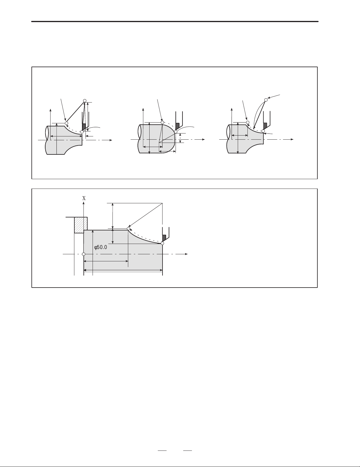
4. INTERPOLA TION FUNCTIONS
Examples
D Command of circular
interpolation X, Z
PROGRAMMING
B–62754EN/01
G02X_Z_I_K_F_; G03X_Z_I_K_F_;
End point
X–axis
X
Z
Center of arc
K
(Absolute programming)
(Diameter
programming)
Start point
Z–axis Z–axis Z–axis
End point
X–axis X–axis
X
Z
K
(Absolute programming)
X
15.0
R25.0
10.0
φ50.0
30.0
G02X_Z_R_F_;
End point
(Diameter
programming)
Start point
X
Z
(Absolute programming)
(Diameter programming)
G02X50.0Z30.0I25.0F0.3; or
G02U20.0W–020.0I25.0F0.3; or
G02X50.0Z30.0R25.0F0.3 or
G02U20.0W–20.0R25.F0.3;
Z
Center of arc
R
(Diameter
programming)
Start point
50.0
48
Page 69
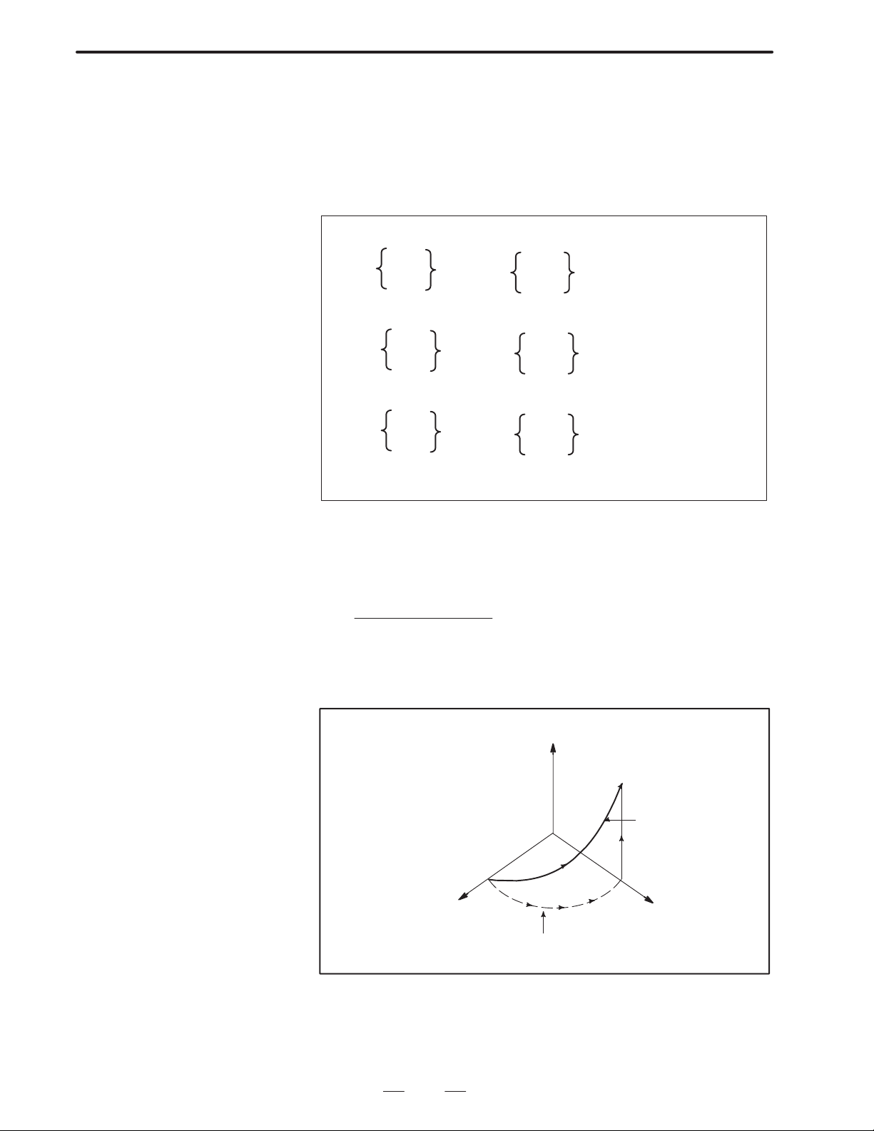
B–62754EN/01
PROGRAMMING
4. INTERPOLA TION FUNCTIONS
4.4
HELICAL
INTERPOLATION
(G02, G03)
Format
Helical interpolation which moved helically is enabled by specifying up
to two other axes which move synchronously with the circular
interpolation by circular commands.
Synchronously with arc of XpYp plane
G17
Synchronously with arc of ZpXp plane
G18
Synchronously with arc of YpZp plane
G19
α,β:Any one axis where circular interpolation is not applied
G02
G03
G02
G03
G02
G03
Up to two other axes can be specified.
XpYp
XpZp
YpZp
IJ
R
IK
R
JK
R
αβF
αβF
αβF
.
Explanations
The command method is to simply or secondary add a move command
axis which is not circular interpolation axes. An F command specifies a
feed rate along a circular arc. Therefore, the feed rate of the linear axis
is as follows:
Length of linear axis
F×
Length of circular arc
Determine the feed rate so the linear axis feed rate does not exceed any
of the various limit values. Bit 0 (HFC) of parameter No. 1404 can be used
to prevent the linear axis feedrate from exceeding various limit values.
Z
Tool path
YX
The feedrate along the circumference of two circular interpolated axes is the specified feedrate.
Limitations
D Cutter compensation is applied only for a circular arc.
D T ool offset and tool length compensation cannot be used in a block in
which a helical interpolation is commanded.
49
Page 70
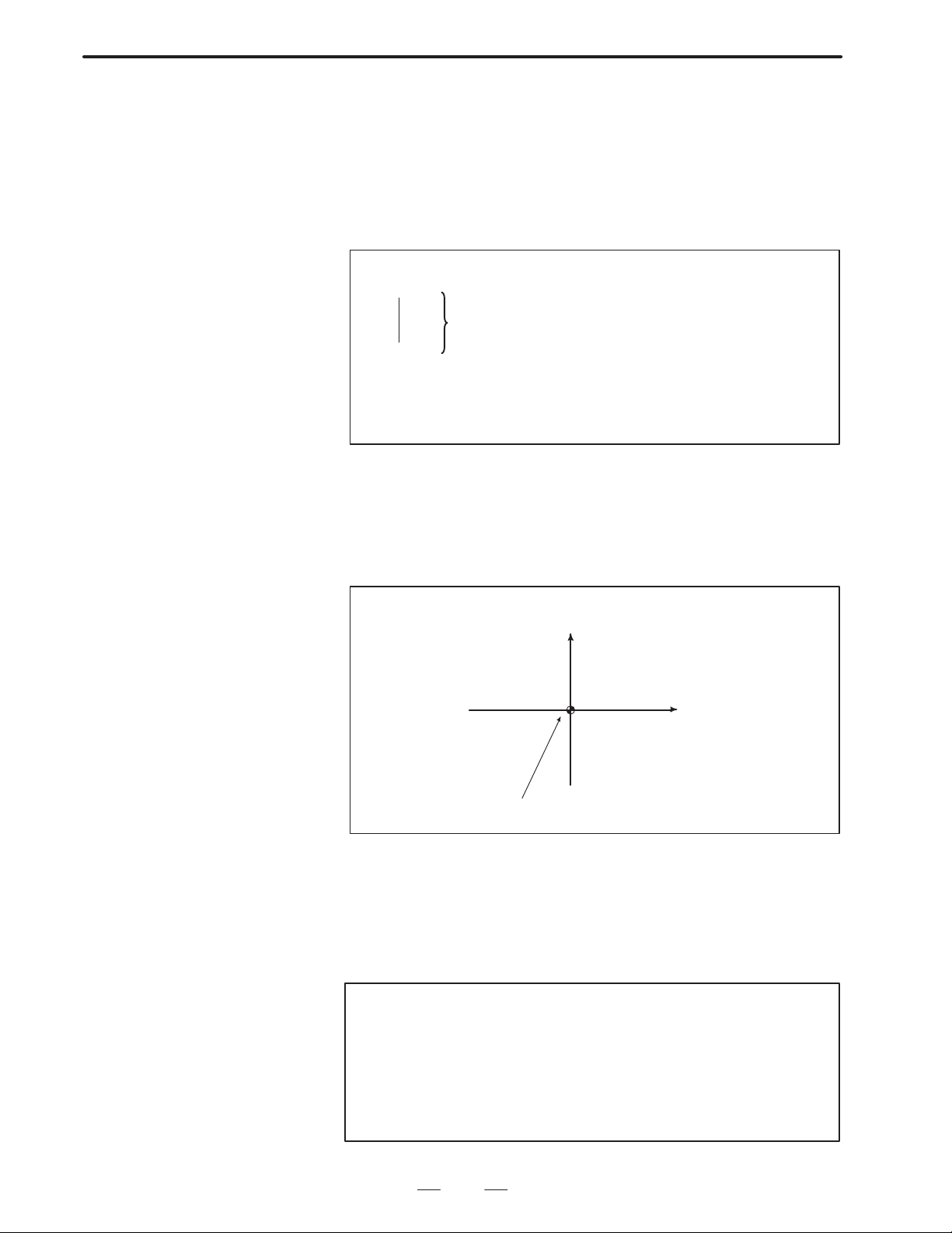
4. INTERPOLA TION FUNCTIONS
PROGRAMMING
B–62754EN/01
4.5
POLAR COORDINA TE
INTERPOLA TION
(G12.1, G13.1)
Format
D Specify G12.1 and G13.1
in Separate Blocks.
Explanations
D Polar coordinate
interpolation plane
Polar coordinate interpolation is a function that exercises contour control
in converting a command programmed in a Cartesian coordinate system
to the movement of a linear axis (movement of a tool) and the movement
of a rotary axis (rotation of a workpiece). This method is useful in cutting
a front surface and grinding a cam shaft on a lathe.
G12.1 ;
G13.1 ;
Starts polar coordinate interpolation mode (enables
polar coordinate interpolation)
Specify linear or circular interpolation using coordinates
in a Cartesian coordinate system consisting of a linear
axis and rotary axis (virtual axis).
Polar coordinate interpolation mode is cancelled (for
not performing polar coordinate interpolation)
G112 and G113 can be used in place of G12.1 and G13.1,
respectively.
G12.1 starts the polar coordinate interpolation mode and selects a polar
coordinate interpolation plane (Fig. 4.5 (a)). Polar coordinate
interpolation is performed on this plane.
Rotary axis (virtual axis)
(unitmm or inch)
Linear axis
(unit:mm or inch)
Origin of the workpiece coordinate system
Fig4.5 (a) Polar coordinate interpolation plane.
When the power is turned on or the system is reset, polar coordinate
interpolation is canceled (G13.1).
The linear and rotation axes for polar coordinate interpolation must be set
in parameters (No. 5460 and 5461) beforehand.
CAUTION
The plane used before G12.1 is specified (plane selected
by G17, G18, or G19) is canceled. It is restored when G13.1
(canceling polar coordinate interpolation) is specified.
When the system is reset, polar coordinate interpolation is
canceled and the plane specified by G17, G18, or G19 is
used.
50
Page 71

B–62754EN/01
PROGRAMMING
4. INTERPOLA TION FUNCTIONS
D Distance moved and
feedrate for polar
coordinate interpolation
The unit for coordinates
on the hypothetical axis
is the same as the unit for
the linear axis (mm/inch)
The unit for the feedrate
is mm/min or inch/min
D G codes which can be
specified in the polar
coordinate interpolation
mode
D Circular interpolation in
the polar coordinate
plane
In the polar coordinate interpolation mode, program commands are
specified with Cartesian coordinates on the polar coordinate interpolation
plane. The axis address for the rotation axis is used as the axis address
for the second axis (virtual axis) in the plane. Whether a diameter or
radius is specified for the first axis in the plane is the same as for the
rotation axis regardless of the specification for the first axis in the plane.
The virtual axis is at coordinate 0 immediately after G12.1 is specified.
Polar interpolation is started assuming the angle of 0 for the position of
the tool when G12.1 is specified.
Specify the feedrate as a speed (relative speed between the workpiece and
tool) tangential to the polar coordinate interpolation plane (Cartesian
coordinate system) using F.
G01 Linear interpolation............
G02, G03
G04
G40, G41, G42
Circular interpolation.........
Dwell.............
Tool nose radius compensation . . . .
(Polar coordinate interpolation is applied to the
path after cutter compensation.)
G65, G66, G67 Custom macro command....
G98, G99
Feed per minute, feed per revolution.........
The addresses for specifying the radius of an arc for circular interpolation
(G02 or G03) in the polar coordinate interpolation plane depend on the
first axis in the plane (linear axis).
D I and J in the Xp–Y p plane when the linear axis is the X–axis or an axis
parallel to the X–axis.
D J and K in the Yp–Zp plane when the linear axis is Y–axis or an axis
parallel to the Y–axis.
D K and I in the Zp–Xp plane when the linear axis is the Z–axis or an axis
parallel to the Z–axis.
D Movement along axes
not in the polar
coordinate interpolation
plane in the polar
coordinate interpolation
mode
D Current position display
in the polar coordinate
interpolation mode
The radius of an arc can be specified also with an R command.
NOTE
The U–, V–, and W–axes (parallel with the basic axis) can
be used with G–codes B and C.
The tool moves along such axes normally, independent of polar
coordinate interpolation.
Actual coordinates are displayed. However, the remaining distance to
move in a block is displayed based on the coordinates in the polar
coordinate interpolation plane (Cartesian coordinates).
51
Page 72
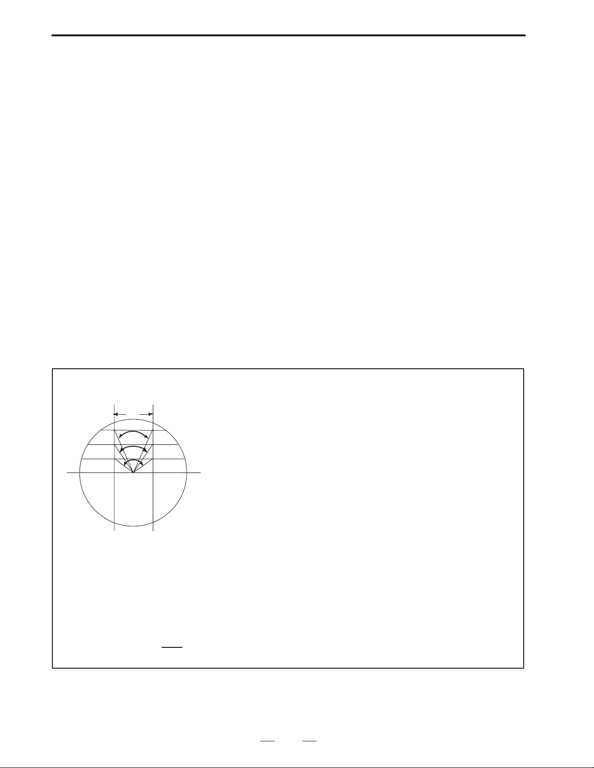
4. INTERPOLA TION FUNCTIONS
Restrictions
PROGRAMMING
B–62754EN/01
D
Coordinate system for the
polar coordinate
interpolation
D Tool nose radius
D Program restart
D Cutting feedrate for the
rotation axis
Before G12.1 is specified, a workpiece coordinate system) where the
center of the rotary axis is the origin of the coordinate system must be set.
In the G12.1 mode, the coordinate system must not be changed (G92,
G52, G53, relative coordinate reset, G54 through G59, etc.).
The polar coordinate interpolation mode cannot be started or terminated
(G12.1 or G13.1) in the tool nose radius compensation mode (G41 or
G42). G12.1 or G13.1 must be specified in the tool nose radius
compensation canceled mode (G40).
For a block in the G12.1 mode, the program cannot be restarted.
Polar coordinate interpolation converts the tool movement for a figure
programmed in a Cartesian coordinate system to the tool movement in the
rotation axis (C–axis) and the linear axis (X–axis). When the tool moves
closer to the center of the workpiece, the C–axis component of the
feedrate becomes larger and may exceed the maximum cutting feedrate
for the C–axis (set in parameter (No. 1422)), causing an alarm (see the
figure below). To prevent the C–axis component from exceeding the
maximum cutting feedrate for the C–axis, reduce the feedrate specified
with address F or create a program so that the tool (center of the tool when
tool nose radius compensation is applied) does not move close to the
center of the workpiece.
WARNING
Consider lines L1, L2, and L3. ∆X is the distance the tool moves
∆
θ2
θ1
θ3
X
L1
per time unit at the feedrate specified with address F in the
Cartesian coordinate system. As the tool moves from L1 to L2 to
L3, the angle at which the tool moves per time unit corresponding
to ∆X in the Cartesian coordinate system increases fromθ1 toθ 2
L2
to θ3.
L3
In other words, the C–axis component of the feedrate becomes
larger as the tool moves closer to the center of the workpiece.
The C component of the feedrate may exceed the maximum
cutting feedrate for the C–axis because the tool movement in the
Cartesian coordinate system has been converted to the tool
movement for the C–axis and the X–axis.
L :Distance (in mm) between the tool center and workpiece center when the tool center is the
nearest to the workpiece center
R :Maximum cutting feedrate (deg/min) of the C axis
Then, a speed specifiable with address F in polar coordinate interpolation can be given by the
formula below. Specify a speed allowed by the formula. The formula provides a theoretical
value; in practice, a value slightly smaller than a theoretical value may need to be used due to
a calculation error.
π
F < L × R ×
180
(mm/min)
D Diameter and radius
programming
Even when diameter programming is used for the linear axis (X–axis),
radius programming is applied to the rotary axis (C–axis).
52
Page 73
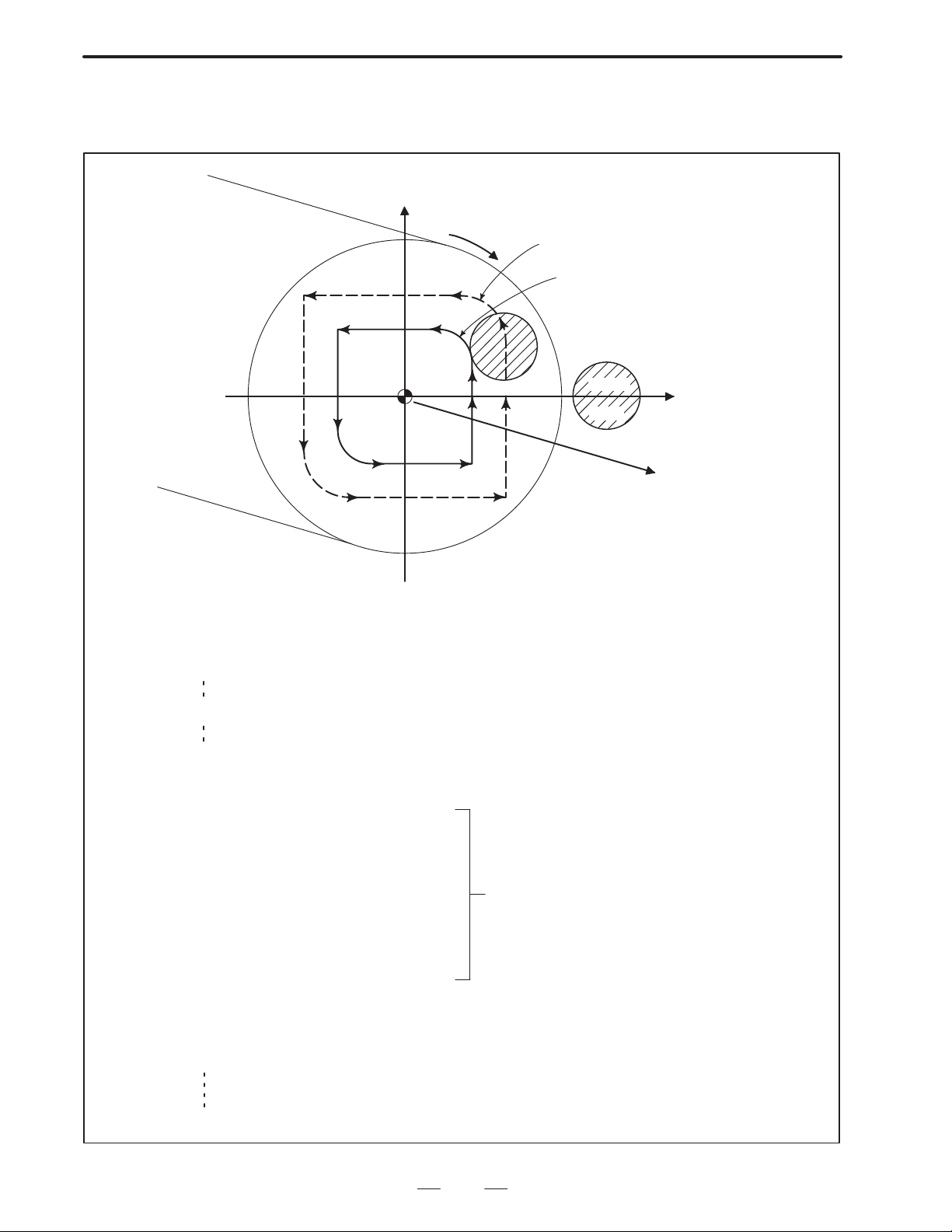
B–62754EN/01
PROGRAMMING
4. INTERPOLA TION FUNCTIONS
Examples
Example of Polar Coordinate Interpolation Program Based on X Axis
(Linear Axis) and C Axis (Rotary Axis)
C’ (hypothetical axis)
N204
N205
N206
C axis
N203
N202
N208
N207
Path after tool nose radius compensation
Program path
N201
N200
X axis
Tool
Z axis
X axis is by diameter programming, C axis is by radius programming.
O0001 ;
N010 T0101
N0100 G00 X120.0 C0 Z _ ; Positioning to start position
N0200 G12.1 ; Start of polar coordinate interpolation
N0201 G42 G01 X40.0 F _ ;
N0202 C10.0 ;
N0203 G03 X20.0 C20.0 R10.0 ;
N0204 G01 X–40.0 ; Geometry program
N0205 C–10.0 ; (program based on cartesian coordinates on
N0206 G03 X–20.0 C–20.0 I10.0 J0 ; X–C’ plane)
N0207 G01 X40.0 ;
N0208 C0 ;
N0209 G40 X120.0 ;
N0210 G13.1 ; Cancellation of polar coordinate interpolation
N0300 Z __ ;
N0400 X __C __ ;
N0900M30 ;
53
Page 74

4. INTERPOLA TION FUNCTIONS
PROGRAMMING
B–62754EN/01
4.6
CYLINDRICAL
INTERPOLATION
(G07.1)
Format
Explanations
D Plane selection
(G17, G18, G19)
The amount of travel of a rotary axis specified by an angle is once
internally converted to a distance of a linear axis along the outer surface
so that linear interpolation or circular interpolation can be performed with
another axis. After interpolation, such a distance is converted back to the
amount of travel of the rotary axis.
The cylindrical interpolation function allows the side of a cylinder to be
developed for programming. So programs such as a program for
cylindrical cam grooving can be created very easily.
G07.1 r ; Starts the cylindrical interpolation mode
(enables cylindrical interpolation).
:
:
:
G07.1 0 ; The cylindrical interpolation mode is cancelled.
: An address for the rotation axis
r : The radius of the cylinder
Specify G07.1 r ; and G07.1 0; in separate blocks.
G107 can be used instead of G07.1.
Use parameter No. 1002 to specify whether the rotation axis is the X–, Y–,
or Z–axis, or an axis parallel to one of these axes. Specify the G code to
select a plane for which the rotation axis is the specified linear axis.
For example, when the rotation axis is an axis parallel to the X–axis, G17
must specify an Xp–Y p plane, which is a plane defined by the rotation axis
and the Y–axis or an axis parallel to the Y–axis.
Only one rotation axis can be set for cylindrical interpolation.
D Feedrate
NOTE
The U–, V–, and W–axes (parallel with the basic axis) can
be used with G–codes B and C.
A feedrate specified in the cylindrical interpolation mode is a speed on the
developed cylindrical surface.
54
Page 75

B–62754EN/01
PROGRAMMING
4. INTERPOLA TION FUNCTIONS
D Circular interpolation
(G02,G03)
D Cutter compensation
D Cylindrical interpolation
accuracy
In the cylindrical interpolation mode, circular interpolation is possible
with the rotation axis and another linear axis. Radius R is used in
commands in the same way as described in Section 4.4.
The unit for a radius is not degrees but millimeters (for metric input) or
inches (for inch input).
< Example Circular interpolation between the Z axis and C axis >
For the C axis of parameter No. 1022, 5 (axis parallel with the X axis)
is to be set. In this case, the command for circular interpolation is
G18 Z__C__;
G02 (G03) Z__C__R__;
For the C axis of parameter No. 1022, 6 (axis parallel with the Y axis)
may be specified instead. In this case, however, the command for
circular interpolation is
G19 C__Z__;
G02 (G03) Z__C__R__;
To perform cutter compensation in the cylindrical interpolation mode,
cancel any ongoing cutter compensation mode before entering the
cylindrical interpolation mode. Then, start and terminate cutter
compensation within the cylindrical interpolation mode.
In the cylindrical interpolation mode, the amount of travel of a rotary axis
specified by an angle is once internally converted to a distance of a linear
axis on the outer surface so that linear interpolation or circular
interpolation can be performed with another axis. After interpolation,
such a distance is converted back to an angle. For this conversion, the
amount of travel is rounded to a least input increment.
So when the radius of a cylinder is small, the actual amount of travel can
differ from a specified amount of travel. Note, however, that such an error
is not accumulative.
If manual operation is performed in the cylindrical interpolation mode
with manual absolute on, an error can occur for the reason described
above.
Restrictions
D Arc radius specification
in the cylindrical
interpolation mode
D Circular interpolation
and tool nose radius
compensation
The actual amount
of travel
MOTION REV
R
MOTION REV
=
2×2πR
The amount of travel per rotation of the rotation axis (Set-
:
ting value of parameter No. 1260)
Workpiece radius
:
:Rounded to the least input increment
Specified value
2×2πR
MOTION REV
In the cylindrical interpolation mode, an arc radius cannot be specified
with word address I, J, or K.
If the cylindrical interpolation mode is started when tool nose radius
compensation is already applied, circular interpolation is not correctly
performed in the cylindrical interpolation mode.
55
Page 76

4. INTERPOLA TION FUNCTIONS
PROGRAMMING
B–62754EN/01
D Positioning
D Coordinate system
setting
D Cylindrical interpolation
mode setting
D Canned cycle for drilling
during cylindrical
interpolation mode
Examples
In the cylindrical interpolation mode, positioning operations (including
those that produce rapid traverse cycles such as G28, G80 through G89)
cannot be specified. Before positioning can be specified, the cylindrical
interpolation mode must be cancelled. Cylindrical interpolation (G07.1)
cannot be performed in the positioning mode (G00).
In the cylindrical interpolation mode, a workpiece coordinate system
G50 cannot be specified.
In the cylindrical interpolation mode, the cylindrical interpolation mode
cannot be reset. The cylindrical interpolation mode must be cancelled
before the cylindrical interpolation mode can be reset.
Canned cycles for drilling, G81 to G89, cannot be specified during
cylindrical interpolation mode.
Example of a Cylindrical Interpolation Program
O0001 (CYLINDRICAL INTERPOLATION );
N01 G00 Z100.0 C0 ;
N02 G01 G18 W0 H0 ;
N03 G07.1 H57299 ;
N04 G01 G42 Z120.0 D01 F250 ;
N05 C30.0 ;
N06 G02 Z90.0 C60.0 R30.0 ;
N07 G01 Z70.0 ;
N08 G03 Z60.0 C70.0 R10.0 ;
N09 G01 C150.0 ;
N10 G03 Z70.0 C190.0 R75.0 ;
N1 1 G01 Z110.0 C230.0 ;
N12 G02 Z120.0 C270.0 R75.0 ;
N13 G01 C360.0 ;
N14 G40 Z100.0 ;
N15 G07.1 C0 ;
N16 M30 ;
C
RZ
mm
120
110
90
70
60
Z
N0
5
N06
N1 1
N07
N08
0
30
60 70
N09
N10
150
N12
230190
270
N13
360
deg
C
56
Page 77

B–62754EN/01
PROGRAMMING
4. INTERPOLA TION FUNCTIONS
4.7
HYPOTHETICAL AXIS
INTERPOLATION
(G07)
Format
Explanations
D Sine interpolation
In helical interpolation, when pulses are distributed with one of the
circular interpolation axes set to a hypothetical axis, sine interpolation is
enable.
When one of the circular interpolation axes is set to a hypothetical axis,
pulse distribution causes the speed of movement along the remaining axis
to change sinusoidally. If the major axis for threading (the axis along
which the machine travels the longest distance) is set to a hypothetical
axis, threading with a fractional lead is enabled. The axis to be set as the
hypothetical axis is specified with G07.
G07 0; Hypothetical axis setting
G07 1; Hypothetical axis cancel
Where, is any one of the addresses of the controlled axes.
The axis is regarded as a hypothetical axis for the period of time from
the G07 0 command until the G07 1 command appears.
Suppose sine interpolation is performed for one cycle in the YZ plane.
The hypothetical axis is them the X axis.
2
X
+ Y2 = R2 (r is the radius of an arc.)
Y = r SIN (
2
Z )
1
1 is the distance traveled along the Z–axis in one cycle.)
D Interlock, stroke limit,
and external
deceleration
D Handle interrupt
Y
r
0
2
2
1
Z
Interlock, stroke limit, and external deceleration can also apply to the
hypothetical axis.
An interrupt caused by the handle also applies to the hypothetical axis.
This means that movement for a handle interrupt is performed.
57
Page 78

4. INTERPOLA TION FUNCTIONS
Limitations
PROGRAMMING
B–62754EN/01
D Manual operation
D Move command
D Coordinate rotation
Examples
D Sine interpolation
The hypothetical axis can be used only in automatic operation. In manual
operation, it is not used, and movement takes place.
Specify hypothetical axis interpolation only in the incremental mode.
Hypothetical axis interpolation does not support coordinate rotation.
Y
10.0
0
20.0
Z
D Changing the feedrate to
form a sine curve
N001 G07 X0 ;
N002 G91 G17 G03 X–20.0 Y0.0 I–10.0 Z20.0 F100 ;
N003 G01 X10.0 ;
N004 G07 X1 ;
From the N002 to N003 blocks, the X–axis is set to a hypothetical axis.
The N002 block specifies helical cutting in which the Z–axis is the linear
axis. Since no movement takes place along the X axis, movement along
the Y–axis is performed while performing sine interpolation along the
Z–axis.
In the N003 block, there is no movement along the X–axis, and so the
machine dwells until interpolation terminates.
(Sample program)
G07Z0 ; The Z–axis is set to a hypothetical axis.
G02X0Z0I10.0F4. ; The feedrate on the X–axis changes sinusoidally.
G07Z1 ; The use of the Z–axis as a hypothetical axis is
canceled.
F
4.0
58
Xt
Page 79

B–62754EN/01
PROGRAMMING
4. INTERPOLA TION FUNCTIONS
4.8
CONSTANT LEAD THREADING (G32)
L
Fig. 4.8 (a) Straight Thread
Format
T apered screws and scroll threads in addition to equal lead straight threads
can be cut by using a G32 command.
The spindle speed is read from the position coder on the spindle in real
time and converted to a cutting feedrate for feed–per minute mode, which
is used to move the tool.
L
L
Fig. 4.8 (b) T apered Screw
Fig. 4.8 (c) Scroll Thread
G32_F_;
_: End point
F_: Lead of the long axis
(always radius programming)
Explanations
X axis
End point
δ
X
0
Fig. 4.8 (d) Example of Thread Cutting
2
Z
α
δ
1
L
Start point
Z axis
In general, thread cutting is repeated along the same tool path in rough
cutting through finish cutting for a screw . Since thread cutting starts when
the position coder mounted on the spindle outputs a 1–turn signal,
threading is started at a fixed point and the tool path on the workpiece is
unchanged for repeated thread cutting. Note that the spindle speed must
remain constant from rough cutting through finish cutting. If not,
incorrect thread lead will occur.
59
Page 80

4. INTERPOLA TION FUNCTIONS
mm in ut
0.0001 to 500.0000mm
Inch in ut
0.000001 inch to 9.999999inch
PROGRAMMING
X
Tapered thread
LX
α
LZ
αx45° lead is LZ
αy45° lead is LX
Fig. 4.8 (e) LZ and LX of a Tapered Thread
B–62754EN/01
Z
In general, the lag of the servo system, etc. will produce somewhat
incorrect leads at the starting and ending points of a thread cut. To
compensate for this, a threading length somewhat longer than required
should be specified.
Table 4.8 (a) lists the ranges for specifying the thread lead.
T able. 4.8 (a) Ranges of lead sizes that can be specified
Least command increment
p
p
60
Page 81

B–62754EN/01
Explanations
1. Straight thread cutting
X axis
PROGRAMMING
30mm
4. INTERPOLA TION FUNCTIONS
The following values are used in programming :
Thread lead :4mm
=3mm
δ
1
δ2=1.5mm
Depth of cut :1mm (cut twice)
(Metric input, Diameter programming)
δ
2
2. T apered thread cutting
X axis
φ50
δ
2
φ43
0
30
70
40
δ
1
G00 U–62.0 ;
G32 W–74.5 F4.0 ;
Z axis
G00 U62.0 ;
W74.5 ;
U–64.0 ;
(For the second cut, cut 1mm more)
G32 W–74.5 ;
G00 U64.0 ;
W74.5 ;
The following values are used in programming :
Thread lead : 3.5mm in the direction of the Z axis
=2mm
δ
1
δ2=1mm
Cutting depth in the X axis direction is 1mm
(Cut twice)
(Metric input, Diameter programming)
G00 X 12.0 Z72.0 ;
δ
1
Z axis
φ14
G32 X 41.0 Z29.0 F3.5 ;
G00 X 50.0 ;
Z 72.0 ;
X 10.0 ;
(Cut 1mm more for the second cut)
G32 X 39.0 Z29.0 ;
G00 X 50.0 ;
Z 72.0 ;
61
Page 82

4. INTERPOLA TION FUNCTIONS
PROGRAMMING
B–62754EN/01
WARNING
1 Feedrate override is effective (fixed at 100%) during thread cutting.
2 it is very dangerous to stop feeding the thread cutter without stopping the spindle. This will
suddenly increase the cutting depth. Thus, the feed hold function is ineffective while thread
cutting. If the feed hold button is pressed during thread cutting, the tool will stop after a block
not specifying thread cutting is executed as if the SINGLE BLOCK button were pushed.
However, the feed hold lamp (SPL lamp) lights when the FEED HOLD button on the machine
control panel is pushed. Then, when the tool stops, the lamp is turned off (Single Block stop
status).
3 When the FEED HOLD button is held down, or is pressed again in the first block that does not
specify thread cutting immediately after a thread cutting block, the tool stops at the block that
does not specify thread cutting.
4 When thread cutting is executed in the single block status, the tool stops after execution of the
first block not specifying thread cutting.
5 When the mode was changed from automatic operation to manual operation during thread
cutting, the tool stops at the first block not specifying thread cutting as when the feed hold button
is pushed as mentioned in Note 3.
However, when the mode is changed from one automatic operation mode to another, the tool
stops after execution of the block not specifying thread cutting as for the single block mode in
Note 4.
6 When the previous block was a thread cutting block, cutting will start immediately without
waiting for detection of the 1–turn signal even if the present block is a thread cutting block.
G32Z _ F_ ;
Z _; (A 1–turn signal is not detected before this block.)
G32 ; (Regarded as threading block.)
Z_ F_ ;(One turn signal is also not detected.)
7 Because the constant surface speed control is effective during scroll thread or tapered screw
cutting and the spindle speed changes, the correct thread lead may not be cut. Therefore, do
not use the constant surface speed control during thread cutting. Instead, use G97.
8 A movement block preceding the thread cutting block must not specify chamfering or corner
R.
9 A thread cutting block must not specifying chamfering or corner R.
10The spindle speed override function is disabled during thread cutting. The spindle speed is
fixed at 100%.
11 Thread cycle retract function is ineffective to G32.
62
Page 83
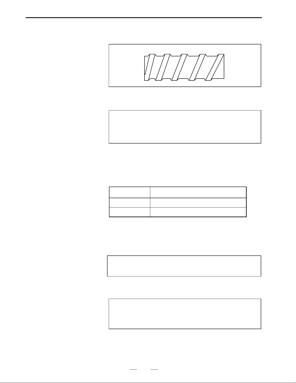
B–62754EN/01
PROGRAMMING
4. INTERPOLA TION FUNCTIONS
4.9
VARIABLE–LEAD
THREAD CUTTING
(G34)
Format
Explanations
Specifying an increment or a decrement value for a lead per screw
revolution enables variable–lead thread cutting to be performed.
Fig. 4.9 (a) Variable–lead screw
G34 _F_K_;
: End point
F : Lead in long
K : Increment and decrement of lead per spindle revolution
itudinal axis direction at the start point
Address other than K are the same as in straight/taper thread cutting with
G32.
Table 4.9 (a) lists a range of values that can be specified as K.
Examples
Table 4.9 (a) Range of valid K values
Metric input 0.0001 to 500.0000 mm/rev
Inch input 0.000001 to9.999999 inch/rev
P/S alarm (No. 14) is produced, for example, when K such that the value
in Table 4.9 (a) is exceeded is directed, the maximum value of lead is
exceeded as a result of increase or decrease by K or the lead has a negative
value.
WARNING
The “Thread Cutting Cycle Retract” is not effective for G34.
Lead at the start point: 8.0 mm
Lead increment: 0.3 mm/rev
G34 Z–72.0 F8.0 K0.3 ;
63
Page 84

4. INTERPOLA TION FUNCTIONS
PROGRAMMING
B–62754EN/01
4.10
CONTINUOUS THREAD CUTTING
Explanations
This function for continuous thread cutting is such that fractional pulses
output to a joint between move blocks are overlapped with the next move
for pulse processing and output (block overlap) .
Therefore, discontinuous machining sections caused by the interruption
of move during continuously block machining are eliminated, thus
making it possible to continuously direct the block for thread cutting
instructions.
Since the system is controlled in such a manner that the synchronism
with the spindle does not deviate in the joint between blocks wherever
possible, it is possible to performed special thread cutting operation in
which the lead and shape change midway.
G32
G32
Fig. 4.10 (a) Continuous Thread Cutting
G32
Even when the same section is repeated for thread cutting while changing
the depth of cut, this system allows a correct machining without impairing
the threads.
NOTE
1 Block overlap is effective even for G01 command,
producing a more excellent finishing surface.
2 When extreme micro blocks continue, no block overlap may
function.
64
Page 85

B–62754EN/01
PROGRAMMING
4. INTERPOLA TION FUNCTIONS
4.1 1
MUL TIPLE–THREAD
CUTTING
Format
Explanations
Using the Q address to specify an angle between the one–spindle–rotation
signal and the start of threading shifts the threading start angle, making
it possible to produce multiple–thread screws with ease.
Multiple–thread screws.
(constant–lead threading)
G32 IP_ F_ Q_ ;
G32 IP_ Q_ ;
_ : End point
F_ : Lead in longitudinal direction
Q_ : Threading start angle
D Available thread cutting
commands
Limitations
D Start angle
D
Start angle increment
D Specifiable start angle
range
D Multiple–thread cutting
(G76)
G32: Constant–lead thread cutting
G34: Variable–lead thread cutting
G76: Multiple–thread cutting cycle
G92: Thread cutting cycle
The start angle is not a continuous–state (modal) value. It must be
specified each time it is used. If a value is not specified, 0 is assumed.
The start angle (Q) increment is 0.001 degrees. Note that no decimal point
can be specified.
Example:
For a shift angle of 180 degrees, specify Q180000.
Q180.000 cannot be specified, because it contains a decimal point.
A start angle (Q) of between 0 and 360000 (in 0.001–degree units) can be
specified. If a value greater than 360000 (360 degrees) is specified, it is
rounded down to 360000 (360 degrees).
For the G76 multiple–thread cutting command, always use the FS15 tape
format.
65
Page 86

4. INTERPOLA TION FUNCTIONS
Examples
PROGRAMMING
Program for producing double–threaded screws
(with start angles of 0 and 180 degrees)
G00 X40.0 ;
G32 W–38.0 F4.0 Q0 ;
G00 X72.0 ;
W38.0 ;
X40.0 ;
G32 W–38.0 F4.0 Q180000
;
G00 X72.0 ;
W38.0 ;
B–62754EN/01
66
Page 87
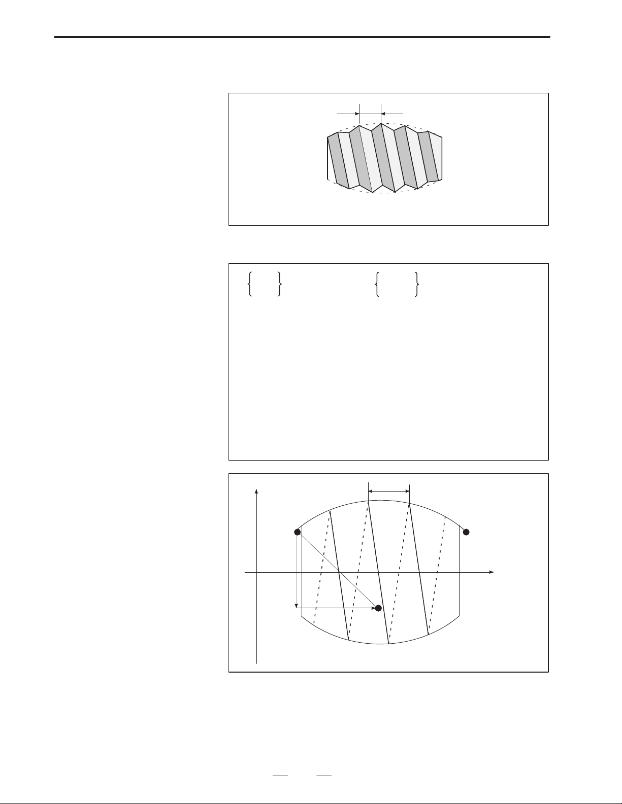
B–62754EN/01
PROGRAMMING
4. INTERPOLA TION FUNCTIONS
4.12
CIRCULAR THREADING (G35, G36)
Format
Using the G35 and G36 commands, a circular thread, having the specified
lead in the direction of the major axis, can be machined.
L
Circular thread
G35
G36
X (U) _ Z (W) _ F _ Q _
G35 : Clockwise circular threading command
G36 : Counterclockwise circular threading command
X (U) : Specify the arc end point (in the same way as for G02,
G03).
Z (W)
I _ K _
R _ _ _
I, K : Specify the arc center relative to the start point, using
relative coordinates (in the same way as for G02, G03).
R : Specify the arc radius.
F : Specify the lead in the direction of the major axis.
Q : Specify the shift of the threading start angle (0 to 360°
in units of 0.001°)
X
Start point
RI
K
F
End point (Z, X)
Z
Arc center
67
Page 88
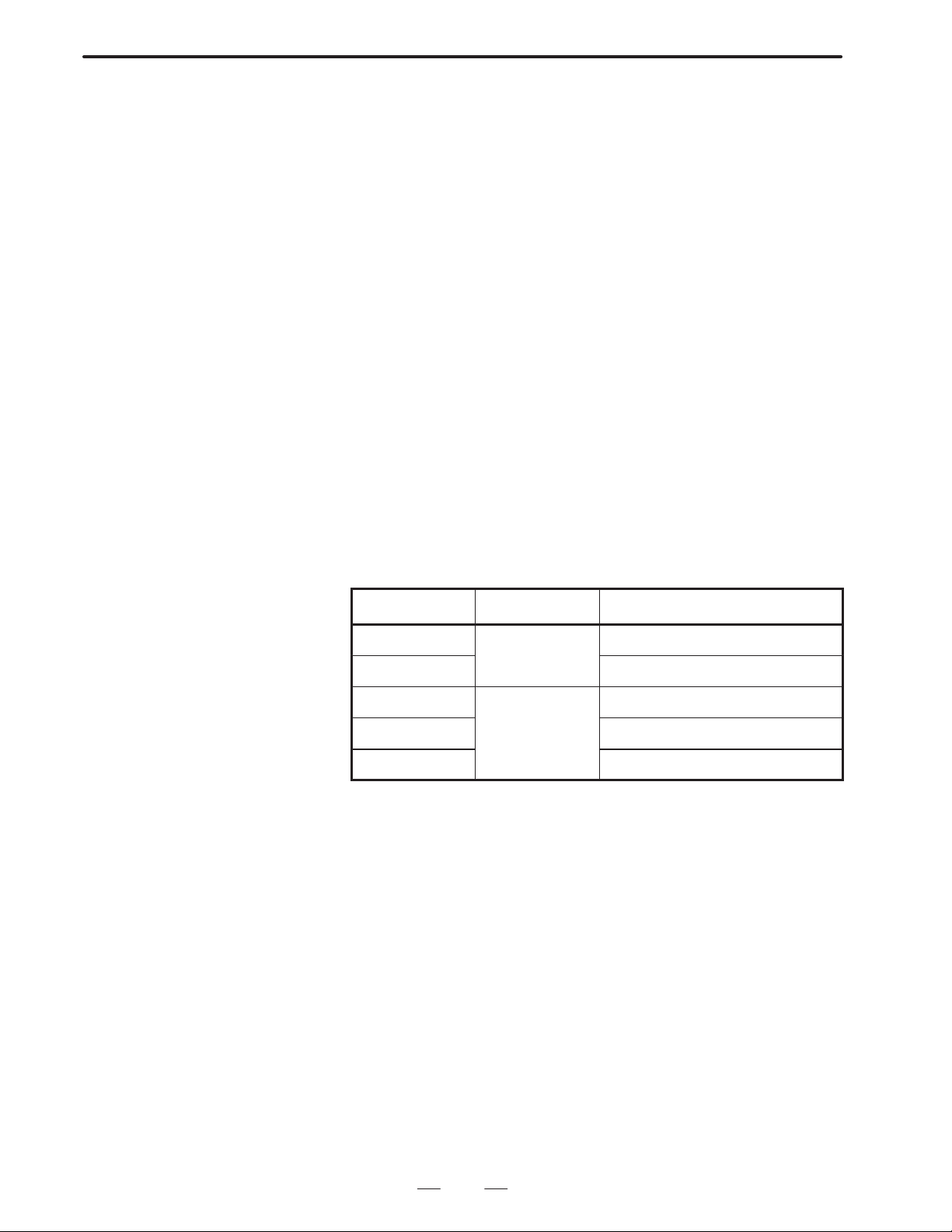
4. INTERPOLA TION FUNCTIONS
01
Explanations
PROGRAMMING
B–62754EN/01
D Specifying the arc radius
D Selecting a plane other
than the ZX plane
D Automatic tool
compensation
If R is specified with I and K, only R is effective.
If an additional axis other than the X– and Z–axes is provided, circular
threading can be specified for a plane other than the ZX plane. The
method of specification is the same as that for G02 and G03.
The G36 command is used to specify the following two functions:
Automatic tool compensation X and counterclockwise circular threading.
The function for which G36 is to be used depends on bit 3 (G36) of
parameter No. 3405.
D When parameter G36 is set to 0, the G36 command is used for
automatic tool compensation X.
D When parameter G36 is set to 1, the G36 command is used for
counterclockwise circular threading.
Automatic tool compensation using G37.1/G37.2
G37.1 can be used to specify automatic tool compensation X and
G37.2 can be used to specify automatic tool compensation Z.
(Specification method)
G37.1 X_
G37.2 Z_
G code when bit 3 of parameter No. 3405 is set to 1
G code G code group Function
G35
G36
G37 Automatic tool compensation Z
G37.1
G37.2 Automatic tool compensation Z
00
Clockwise circular threading
Counterclockwise circular threading
Automatic tool compensation X
68
Page 89
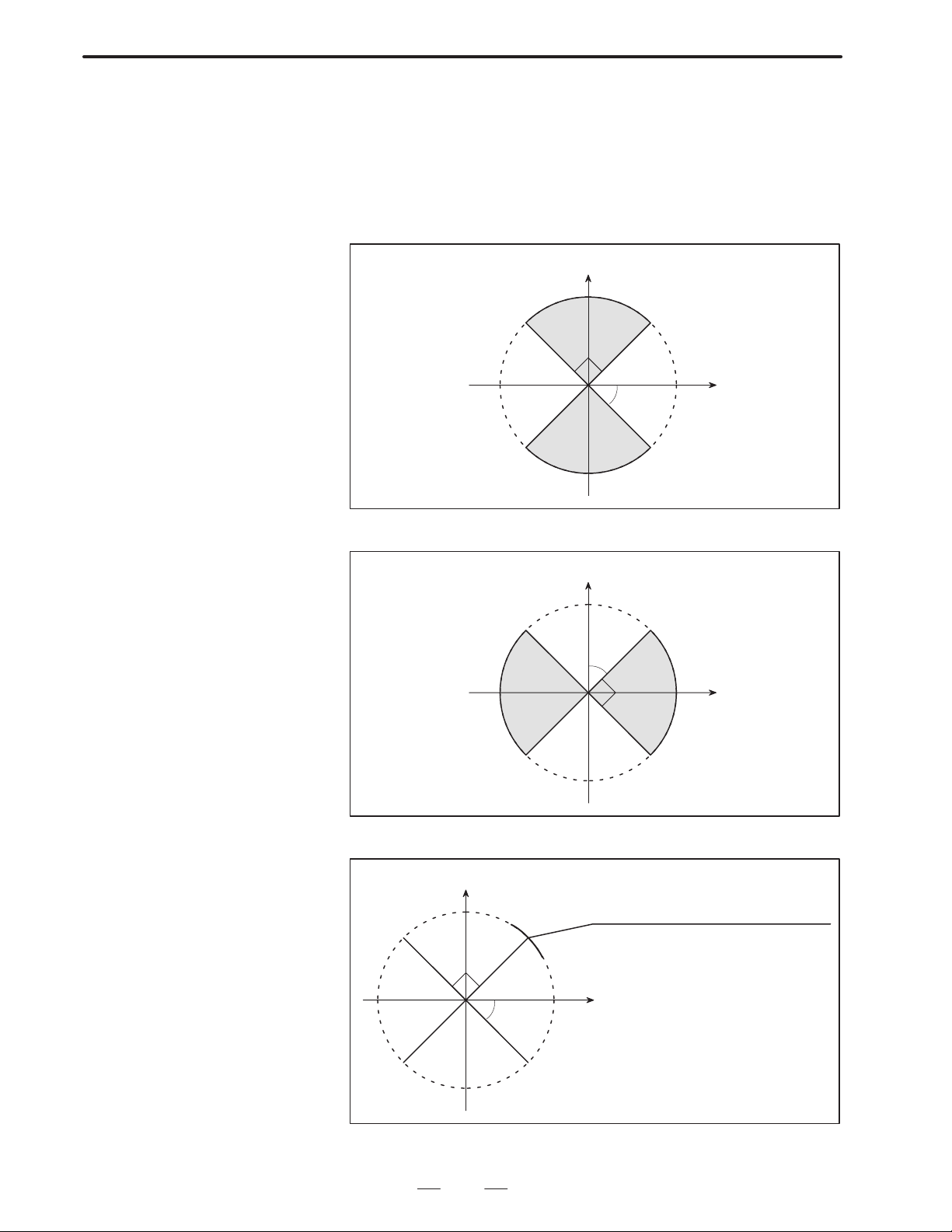
B–62754EN/01
Limitations
PROGRAMMING
4. INTERPOLA TION FUNCTIONS
D Range of specifiable arc
An arc must be specified such that it falls within a range in which the
major axis of the arc is always the Z–axis or always the X–axis, as shown
in Fig. 4.12 (a) and (b). If the arc includes a point at which the major axis
changes from the X–axis to Z–axis, or vice versa, as shown in Fig. 4.12
(c), P/S alarm 5058 is issued.
X
Start point
Fig. 4.12 (a) Range in which the Z–axis is the major axis
X
End point
Z
45°
Start point
45°
Z
End point
Fig. 4.12 (b) Range in which the X–axis is the major axis
X
Start point
45°
The major axis changes at this point.
End point
Z
Fig. 4.12 (c) Example of arc specification which causes an alarm
69
Page 90

4. INTERPOLA TION FUNCTIONS
PROGRAMMING
B–62754EN/01
4.13
SKIP FUNCTION
(G31)
Format
Explanations
Linear interpolation can be commanded by specifying axial move
following the G31 command, like G01. If an external skip signal is input
during the execution of this command, execution of the command is
interrupted and the next block is executed.
The skip function is used when the end of machining is not programmed
but specified with a signal from the machine, for example, in grinding. It
is used also for measuring the dimensions of a workpiece.
For details of how to use this function, refer to the manual supplied by the
machine tool builder.
G31 _ ;
G31: One–shot G code (If is effective only in the block in which
it is specified)
The coordinate values when the skip signal is turned on can be used in a
custom macro because they are stored in the custom macro system
variable #5061 to #5068, as follows:
#5061 X axis coordinate value
#5062 Z axis coordinate value
#5063 3rd axis coordinate value
:
:
#5068 8th axis coordinate value
WARNING
To increase the precision of the tool position when the skip
signal is input, feedrate override, dry run, and automatic
acceleration/deceleration is disabled for the skip function
when the feedrate is specified as a feed per minute value.
To enable these functions, set bit 7 (SKF) of parameter No.
6200 to 1. If the feedrate is specified as a feed per rotation
value, feedrate override, dry run, and automatic
acceleration/deceleration are enabled for the skip function,
regardless of the setting of the SKF bit.
NOTE
1 If G31 command is issued while tool nose radius compensation is
applied, an P/S alarm of No.035 is displayed. Cancel the cutter
compensation with the G40 command before the G31 command
is specified.
2 For the high–speed skip option, executing G31 during feed–per–
rotation mode causes P/S alarm 211 to be generated.
70
Page 91
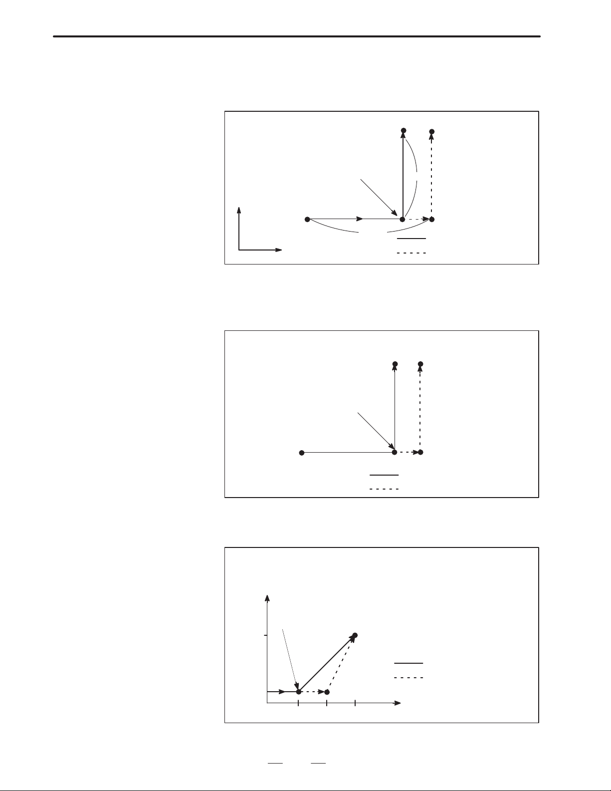
B–62754EN/01
Examples
D The next block to G31 is an
incremental command
PROGRAMMING
G31 W100.0 F100;
U50.0;
4. INTERPOLA TION FUNCTIONS
U50.0
D The next block to G31 is an
absolute command for 1
axis
Skip signal is input here
X
Z
Fig.4.13(a) The next block is an incremental command
G31 Z200.00 F100;
X100.0;
Skip signal is input here
100.0
50.0
W100
Actual motion
Motion without skip signal
X100.0
X200.0
D The next block to G31 is an
absolute command for 2
axes
Actual motion
Motion without skip signal
Fig.4.13(b) The next block is an absolute command for 1 axis
G31 G90X200.0 F100;
X300.0 Z100.0;
X
Skip signal is input here
10
0
100 200 300
Fig 4.13(c) The next block is an absolute command for 2 axes
(300,100)
Actual motion
Motion without skip signal
Z
71
Page 92

4. INTERPOLA TION FUNCTIONS
PROGRAMMING
B–62754EN/01
4.14
MULTISTAGE SKIP
Format
In a block specifying P1 to P4 after G31, the multistage skip function
stores coordinates in a custom macro variable when a skip signal (4–point
or 8–point ; 8–point when a high–speed skip signal is used) is turned on.
Parameters No. 6202 to No. 6205 can be used to select a 4–point or
8–point (when a high–speed skip signal is used) skip signal. One skip
signal can be set to match multiple Pn or Qn (n=1,2,3,4) as well as to
match a Pn or Qn on a one–to–one basis. Parameters DS1 to DS8 (No.
6206 #0A#7) can be used for dwell.
A skip signal from equipment such as a fixed–dimension size measuring
instrument can be used to skip programs being executed.
In plunge grinding, for example, a series of operations from rough
machining to spark–out can be performed automatically by applying a
skip signal each time rough machining, semi–fine machining,
fine–machining, or spark–out operation is completed.
Move command
G31 __ F __ P __ ;
_ : End point
F_ : Feedrate
P_ : P1–P4
Explanations
D Correspondence to skip
signals
Dwell
G04 X (U, P)__ (Q__) ;
X(U, P)_ : Dwell time
Q_ : Q1 – Q4
Multistage skip is caused by specifying P1, P2, P3, or P4 in a G31 block.
For an explanation of selecting (P1, P2, P3, or P4), refer to the manual
supplied by the machine tool builder.
Specifying Q1, Q2, Q3, or Q4 in G04 (dwell command) enables dwell
skip in a similar way to specifying G31. A skip may occur even if Q is
not specified. For an explanation of selecting (Q1, Q2, Q3, or Q4), refer
to the manual supplied by the machine tool builder.
Parameter Nos. 6202 to 6205 can be used to specify whether the 4–point
or 8–point skip signal is used (when a high–speed skip signal is used).
Specification is not limited to one–to–one correspondence. It is possible
to specify that one skip signal correspond to two or more Pn’s or Qn’s
(n=1, 2, 3, 4). Also, bits 0 (DS1) to 7 (DS8) of parameter No. 6206 can
be used to specify dwell.
CAUTION
Dwell is not skipped when Qn is not specified and
parameters DS1–DS8 (No. 6206#0–#7) are not set.
72
Page 93

B–62754EN/01
PROGRAMMING
4. INTERPOLA TION FUNCTIONS
4.15
TORQUE LIMIT SKIP (G31 P99)
Format
Explanations
D G31 P99
With the motor torque limited (for example, by a torque limit command,
issued through the PMC window), a move command following G31 P99
(or G31 P98) can cause the same type of cutting feed as with G01 (linear
interpolation).
With the issue of a signal indicating a torque limit has been reached
(because of pressure being applied or for some other reason), a skip
occurs.
For details of how to use this function, refer to the manuals supplied by
the machine tool builder.
G31 P99 IP_ F_ ;
G31 P98 IP_ F_ ;
G31: One–shot G code (G code effective only in the block in which it
is issued)
If the motor torque limit is reached, or a SKIP signal is received during
execution of G31 P99, the current move command is aborted, and the next
block is executed.
D G31 P98
D Torque limit command
D Custom macro system
variable
Limitations
D Axis command
If the motor torque limit is reached during execution of G31 P98, the
current move command is aborted, and the next block is executed. The
SKIP signal <X0004#7/Tool post 2 X0013#7> does not affect G31 P98.
Entering a SKIP signal during the execution of G31 P98 does not cause
a skip.
If a torque limit is not specified before the execution of G31 P99/98, the
move command continues; no skip occurs even if a torque limit is
reached.
When G31 P99/98 is specified, the custom macro variables hold the
coordinates at the end of a skip. (See Section 4.9.)
If a SKIP signal causes a skip with G31 P99, the custom macro system
variables hold the coordinates based on the machine coordinate system
when it stops, rather than those when the SKIP signal is entered.
Only one axis can be controlled in each block with G31 P98/99.
If two or more axes are specified to be controlled in such blocks, or no axis
command is issued, P/S alarm No. 015 is generated.
D Degree of servo error
D High–speed skip
When a signal indicating that a torque limit has been reached is input
during execution of G31 P99/98, and the degree of servo error exceeds
32767, P/S alarm No. 244 is generated.
With G31 P99, a SKIP signal can cause a skip, but not a high–speed skip.
73
Page 94

4. INTERPOLA TION FUNCTIONS
PROGRAMMING
B–62754EN/01
D Simplified
synchronization and
slanted axis control
D Speed control
D Consecutive commands
G31 P99/98 cannot be used for axes subject to simplified synchronization
or the X–axis or Z–axis when under slanted axis control.
Bit 7 (SKF) of parameter No. 6200 must be set to disable dry run,
override, and auto acceleration or deceleration for G31 skip commands.
Do not use G31 P99/98 in consecutive blocks.
WARNING
Always specify a torque limit before a G31 P99/98
command. Otherwise, G31 P99/98 allows move
commands to be executed without causing a skip.
NOTE
If G31 is issued with tool nose radius compensation
specified, P/S alarm No. 035 is generated. Therefore,
before issuing G31, execute G40 to cancel tool nose radius
compensation.
Examples
O0001 ;
:
:
MJJ ;
:
:
G31 P99 X200. F100 ;
:
G01 X100. F500 ;
:
:
MYY ;
:
:
M30 ;
:
%
The PMC specifies the torque limit
through the window.
Torque limit skip command
Move command for which a torque
limit is applied
Torque limit canceled by the PMC
74
Page 95

B–62754EN/01
5
PROGRAMMING
5. FEED FUNCTIONS
75
Page 96
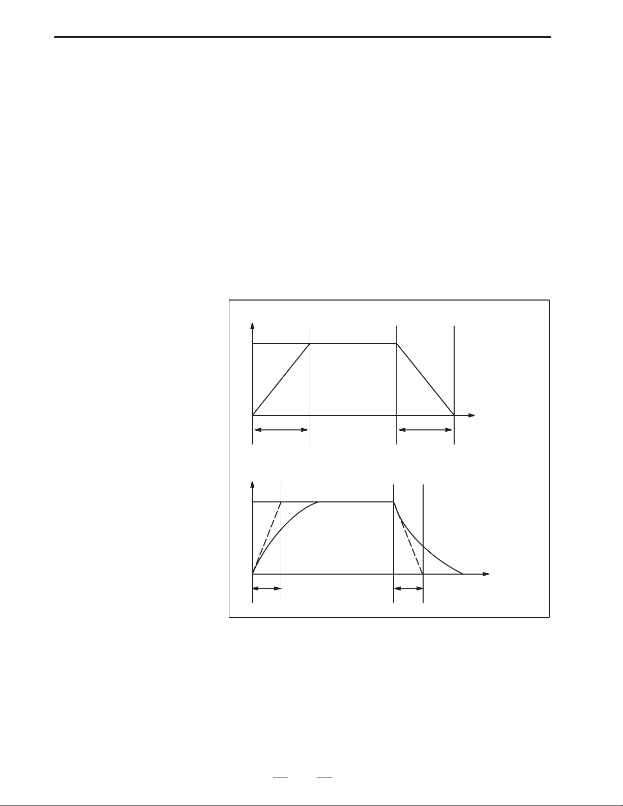
5. FEED FUNCTIONS
PROGRAMMING
B–62754EN/01
5.1
GENERAL
D Feed functions
D Override
D Automatic acceleration/
deceleration
The feed functions control the feedrate of the tool. The following two feed
functions are available:
1. Rapid traverse
When the positioning command (G00) is specified, the tool moves at!a
rapid traverse feedrate set in the CNC (parameter No. 1420).
2. Cutting feed
The tool moves at a programmed cutting feedrate.
Override can be applied to a rapid traverse rate or cutting feedrate using
the switch on the machine operator’s panel.
T o prevent a mechanical shock, acceleration/deceleration is automatically
applied when the tool starts and ends its movement (Fig. 5.1 (a)).
Rapid traverse rate
F
:Rapid traverse
F
R
0
R
rate
: Acceleration/
T
R
deceleration
time constant for
rapid traverse
rate
Time
T
R
Feed rate
F
C
0
T
C
Fig. 5.1 (a) Automatic acceleration/deceleration (example)
T
R
F
: Feedrate
C
: Acceleration/
T
C
T
C
deceleration time
constant for a cutting feedrate
Time
76
Page 97
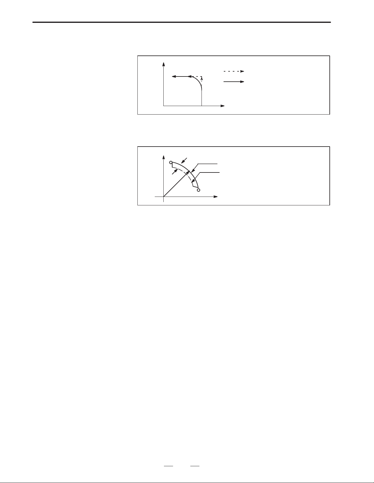
B–62754EN/01
PROGRAMMING
5. FEED FUNCTIONS
D Tool path in a cutting
feed
If the direction of movement changes between specified blocks during
cutting feed, a rounded–corner path may result (Fig. 5.1 (b)).
X
Programmed path
Actual tool path
0
Fig. 5.1 (b) Example of Tool Path between Two Blocks
Z
In circular interpolation, a radial error occurs (Fig. 5.1(c)).
X
∆r:Error
Programmed path
Actual tool path
r
0
Fig. 5.1 (c) Example of Radial Error in Circular Interpolation
Z
The rounded–corner path shown in Fig. 5.1(b) and the error shown in Fig.
5.1(c) depend on the feedrate. So, the feedrate needs to be controlled for
the tool to move as programmed.
77
Page 98

5. FEED FUNCTIONS
5.2
RAPID TRAVERSE
Format
PROGRAMMING
G00 _ ;
G00 : G code (group 01) for positioning (rapid traverse)
_ ; Dimension word for the end point
B–62754EN/01
Explanations
The positioning command (G00) positions the tool by rapid traverse. In
rapid traverse, the next block is executed after the specified feedrate
becomes 0 and the servo motor reaches a certain range set by the machine
tool builder (in–position check).
A rapid traverse rate is set for each axis by parameter No. 1420, so no rapid
traverse feedrate need be programmed.
The following overrides can be applied to a rapid traverse rate with the
switch on the machine operator’s panel:F0, 25, 50, 100%
F0: Allows a fixed feedrate to be set for each axis by parameter No. 1421.
For detailed information, refer to the appropriate manual of the machine
tool builder.
78
Page 99
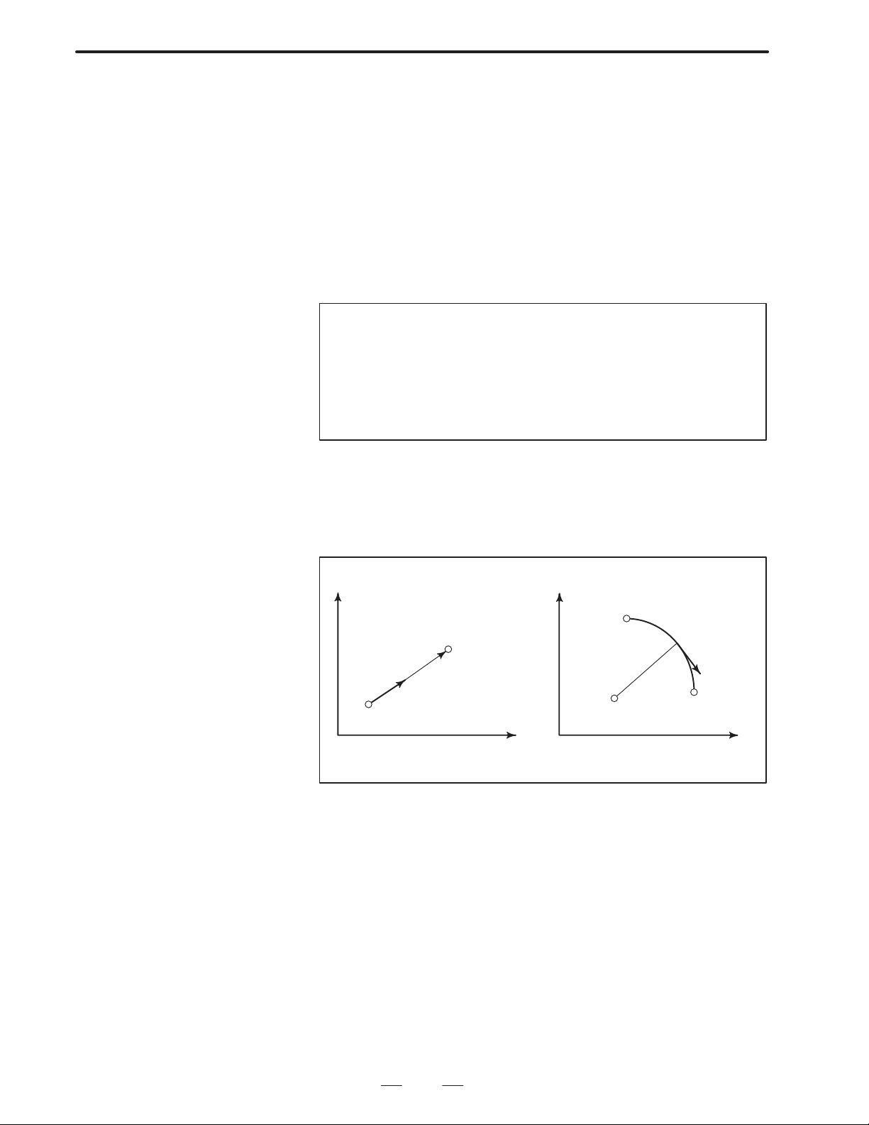
B–62754EN/01
PROGRAMMING
5. FEED FUNCTIONS
5.3
CUTTING FEED
Format
Explanations
Feedrate of linear interpolation (G01), circular interpolation (G02, G03),
etc. are commanded with numbers after the F code.
In cutting feed, the next block is executed so that the feedrate change from
the previous block is minimized.
Two modes of specification are available:
1. Feed per minute (G98)
After F, specify the amount of feed of the tool per minute.
2. Feed per revolution (G99)
After F, specify the amount of feed of the tool per spindle revolution.
Feed per minute
G98 ; G code (group 05) for feed per minute
F_ ; Feedrate command (mm/min or inch/min)
Feed per revolution
G99 ; G code (group 05) for feed per revolution
F_ ; Feedrate command (mm/rev or inch/rev)
D Tangential speed
constant control
D Feed per minute (G98)
Cutting feed is controlled so that the tangential feedrate is always set at
a specified feedrate.
X
End point
F
Start
point
Linear interpolation
Fig. 5.3 (a) T angential feedrate (F)
X
Starting
point
F
Center
ZZ
Circular interpolation
End point
After specifying G98 (in the feed per minute mode), the amount of feed
of the tool per minute is to be directly specified by setting a number after
F . G98 is a modal code. Once a G98 is specified, it is valid until G99 (feed
per revolution) is specified. At power–on, the feed per revolution mode
is set.
An override from 0% to 254% (in 1% steps) can be applied to feed per
minute with the switch on the machine operator’s panel. For detailed
information, see the appropriate manual of the machine tool builder.
79
Page 100

5. FEED FUNCTIONS
PROGRAMMING
B–62754EN/01
D Feed per revolution
(G99)
F
Fig. 5.3 (b) Feed per minute
Feed amount per minute
(mm/min or inch/min)
WARNING
No override can be used for some commands such as for
threading.
After specifying G99 (in the feed per revolution mode), the amount of
feed of the tool per spindle revolution is to be directly specified by setting
a number after F . G99 is a modal code. Once a G99 is specified, it is valid
until G98 (feed per minute) is specified.
An override from 0% to 254% (in 1% steps) can be applied to feed per
revolution with the switch on the machine operator’s panel. For detailed
information, see the appropriate manual of the machine tool builder.
If bit 0 (NPC) of parameter No. 1402 has been set to 1, feed–per–rotation
commands can be specified even when a position coder is not being used.
(The CNC converts feed–per–rotation commands to feed–per–minute
commands.)
F
Fig. 5.3 (c) Feed per revolution
Feed amount per spindle revolution
(mm/rev or inch/rev)
CAUTION
When the speed of the spindle is low, feedrate fluctuation
may occur. The slower the spindle rotates, the more
frequently feedrate fluctuation occurs.
D Cutting feedrate clamp
A common upper limit can be set on the cutting feedrate along each axis
with parameter No. 1422. If an actual cutting feedrate (with an override
applied) exceeds a specified upper limit, it is clamped to the upper limit.
80
 Loading...