

Page 1

C
8
/
-
C
FANU
Series 16/1
160/180
Descriptions
Model
B-62752EN/01
Page 2

• No part of this manual may be reproduced in any form.
• All specifications and designs are subject to change without notice.
The export of this product is subject to the authorization of the government of the country
from where the product is exported.
In this manual we have tried as much as possible to describe all the various matters.
However, we cannot describe all the matters which must not be done, or which cannot be
done, because there are so many possibilities.
Therefore, matters which are not especially described as possible in this manual should be
regarded as ”impossible”.
This manual contains the program names or device names of other companies, some of
which are registered trademarks of respective owners. However, these names are not
followed by or in the main body.
Page 3

B–62752EN/01
Table of contents
I. GENERAL 1. . . . . . . . . . . . . . . . . . . . . . . . . . . . . . . . . . . . . . . . . . . . . . . . . . . . .
1. GENERAL 3. . . . . . . . . . . . . . . . . . . . . . . . . . . . . . . . . . . . . . . . . . . . . . . . . . . . . . . . . . . .
2. LIST OF SPECIFICATIONS 5. . . . . . . . . . . . . . . . . . . . . . . . . . . . . . . . . . . . . . . . . . . . .
II. NC FUCNTION 17. . . . . . . . . . . . . . . . . . . . . . . . . . . . . . . . . . . . . . . . . . . . . . . .
PREFACE 19. . . . . . . . . . . . . . . . . . . . . . . . . . . . . . . . . . . . . . . . . . . . . . . . . . . . . . . . . . . . .
1. CONTROLLED AXES 20. . . . . . . . . . . . . . . . . . . . . . . . . . . . . . . . . . . . . . . . . . . . . . . . . .
1.1 NUMBER OF THE ALL CONTROLLED AXES 20. . . . . . . . . . . . . . . . . . . . . . . . . . . . . . . . . . . . . . . .
1.2 MACHINE CONTROLLED AXES 21. . . . . . . . . . . . . . . . . . . . . . . . . . . . . . . . . . . . . . . . . . . . . . . . . . .
1.2.1 Number of Controlled Paths (T Series) 21. . . . . . . . . . . . . . . . . . . . . . . . . . . . . . . . . . . . . . . . . . . . . . . .
1.2.2 Number of Basic Controlled Axes 21. . . . . . . . . . . . . . . . . . . . . . . . . . . . . . . . . . . . . . . . . . . . . . . . . . . .
1.2.3 Number of Basic Simultaneously Controlled Axes 21. . . . . . . . . . . . . . . . . . . . . . . . . . . . . . . . . . . . . . . .
1.2.4 Number of Controlled Axes Expanded (All) 21. . . . . . . . . . . . . . . . . . . . . . . . . . . . . . . . . . . . . . . . . . . . .
1.2.5 Number of Simultaneously Controlled Axes Expanded (All) 21. . . . . . . . . . . . . . . . . . . . . . . . . . . . . . . .
1.2.6 Axis Control by PMC 21. . . . . . . . . . . . . . . . . . . . . . . . . . . . . . . . . . . . . . . . . . . . . . . . . . . . . . . . . . . . . .
1.2.7 Cs Contour Control 21. . . . . . . . . . . . . . . . . . . . . . . . . . . . . . . . . . . . . . . . . . . . . . . . . . . . . . . . . . . . . . . .
1.3 LOADER CONTROLLED AXES 22. . . . . . . . . . . . . . . . . . . . . . . . . . . . . . . . . . . . . . . . . . . . . . . . . . . .
1.4 AXIS NAMES 22. . . . . . . . . . . . . . . . . . . . . . . . . . . . . . . . . . . . . . . . . . . . . . . . . . . . . . . . . . . . . . . . . . .
1.5 INCREMENT SYSTEM 23. . . . . . . . . . . . . . . . . . . . . . . . . . . . . . . . . . . . . . . . . . . . . . . . . . . . . . . . . . .
1.5.1 Input Unit (10 Times) 24. . . . . . . . . . . . . . . . . . . . . . . . . . . . . . . . . . . . . . . . . . . . . . . . . . . . . . . . . . . . . .
1.6 MAXIMUM STROKE 24. . . . . . . . . . . . . . . . . . . . . . . . . . . . . . . . . . . . . . . . . . . . . . . . . . . . . . . . . . . . .
2. PREPARATORY FUNCTIONS 25. . . . . . . . . . . . . . . . . . . . . . . . . . . . . . . . . . . . . . . . . . .
2.1 T SERIES 26. . . . . . . . . . . . . . . . . . . . . . . . . . . . . . . . . . . . . . . . . . . . . . . . . . . . . . . . . . . . . . . . . . . . . . .
2.2 M SERIES 29. . . . . . . . . . . . . . . . . . . . . . . . . . . . . . . . . . . . . . . . . . . . . . . . . . . . . . . . . . . . . . . . . . . . . . .
3. INTERPOLATION FUNCTIONS 32. . . . . . . . . . . . . . . . . . . . . . . . . . . . . . . . . . . . . . . . . .
3.1 POSITIONING (G00) 33. . . . . . . . . . . . . . . . . . . . . . . . . . . . . . . . . . . . . . . . . . . . . . . . . . . . . . . . . . . . . .
3.2 SINGLE DIRECTION POSITIONING (G60) (M SERIES) 34. . . . . . . . . . . . . . . . . . . . . . . . . . . . . . . .
3.3 LINEAR INTERPOLATION (G01) 35. . . . . . . . . . . . . . . . . . . . . . . . . . . . . . . . . . . . . . . . . . . . . . . . . . .
3.4 CIRCULAR INTERPOLATION (G02, G03) 36. . . . . . . . . . . . . . . . . . . . . . . . . . . . . . . . . . . . . . . . . . .
3.5 HELICAL INTERPOLATION (G02, G03) 37. . . . . . . . . . . . . . . . . . . . . . . . . . . . . . . . . . . . . . . . . . . . .
3.6 POLAR COORDINATE INTERPOLATION (G12.1, G13.1) 38. . . . . . . . . . . . . . . . . . . . . . . . . . . . . . .
3.7 CYLINDRICAL INTERPOLATION (G07.1) 40. . . . . . . . . . . . . . . . . . . . . . . . . . . . . . . . . . . . . . . . . . .
3.8 INVOLUTE INTERPOLATION (G02.2, G03.2) (M SERIES) 42. . . . . . . . . . . . . . . . . . . . . . . . . . . . . .
3.9 EXPONENTIAL FUNCTION INTERPOLATION (G02.3, G03.3) (M SERIES) 43. . . . . . . . . . . . . . .
3.10 SMOOTH INTERPOLATION (G05.1) (M SERIES) 45. . . . . . . . . . . . . . . . . . . . . . . . . . . . . . . . . . . . .
3.11 HYPOTHETICAL AXIS INTERPOLATION (G07) 46. . . . . . . . . . . . . . . . . . . . . . . . . . . . . . . . . . . . . .
4. THREAD CUTTING 47. . . . . . . . . . . . . . . . . . . . . . . . . . . . . . . . . . . . . . . . . . . . . . . . . . . .
4.1 EQUAL LEAD THREAD CUTTING (G33) (WITH G CODE SYSTEM A: G32) 48. . . . . . . . . . . . . .
4.2 MULTIPLE–THREAD CUTTING (G33) 49. . . . . . . . . . . . . . . . . . . . . . . . . . . . . . . . . . . . . . . . . . . . . .
i
Page 4

Table of contents
B–62752EN/01
4.3 VARIABLE LEAD THREAD CUTTING (G34) (T SERIES) 50. . . . . . . . . . . . . . . . . . . . . . . . . . . . . .
4.4 CONTINUOUS THREAD CUTTING (T SERIES) 50. . . . . . . . . . . . . . . . . . . . . . . . . . . . . . . . . . . . . .
4.5 CIRCULAR THREADING (G35, G36) (T SERIES) 51. . . . . . . . . . . . . . . . . . . . . . . . . . . . . . . . . . . . .
5. FEED FUNCTIONS 52. . . . . . . . . . . . . . . . . . . . . . . . . . . . . . . . . . . . . . . . . . . . . . . . . . . . .
5.1 RAPID TRAVERSE 53. . . . . . . . . . . . . . . . . . . . . . . . . . . . . . . . . . . . . . . . . . . . . . . . . . . . . . . . . . . . . . .
5.2 CUTTING FEED RATE 54. . . . . . . . . . . . . . . . . . . . . . . . . . . . . . . . . . . . . . . . . . . . . . . . . . . . . . . . . . . .
5.2.1 Tangential Speed Constant Control 54. . . . . . . . . . . . . . . . . . . . . . . . . . . . . . . . . . . . . . . . . . . . . . . . . . . .
5.2.2 Cutting Feed Rate Clamp 54. . . . . . . . . . . . . . . . . . . . . . . . . . . . . . . . . . . . . . . . . . . . . . . . . . . . . . . . . . .
5.2.3 Per Minute Feed (G94) 54. . . . . . . . . . . . . . . . . . . . . . . . . . . . . . . . . . . . . . . . . . . . . . . . . . . . . . . . . . . . .
5.2.4 Per Revolution Feed (G95) 55. . . . . . . . . . . . . . . . . . . . . . . . . . . . . . . . . . . . . . . . . . . . . . . . . . . . . . . . . .
5.2.5 Inverse Time Feed (G93) (M Series) 55. . . . . . . . . . . . . . . . . . . . . . . . . . . . . . . . . . . . . . . . . . . . . . . . . . .
5.2.6 F1–digit Feed (M Series) 55. . . . . . . . . . . . . . . . . . . . . . . . . . . . . . . . . . . . . . . . . . . . . . . . . . . . . . . . . . . .
5.3 OVERRIDE 56. . . . . . . . . . . . . . . . . . . . . . . . . . . . . . . . . . . . . . . . . . . . . . . . . . . . . . . . . . . . . . . . . . . . .
5.3.1 Feed Rate Override 56. . . . . . . . . . . . . . . . . . . . . . . . . . . . . . . . . . . . . . . . . . . . . . . . . . . . . . . . . . . . . . . .
5.3.2 Second Feed Rate Override 56. . . . . . . . . . . . . . . . . . . . . . . . . . . . . . . . . . . . . . . . . . . . . . . . . . . . . . . . . .
5.3.3 Rapid Traverse Override 56. . . . . . . . . . . . . . . . . . . . . . . . . . . . . . . . . . . . . . . . . . . . . . . . . . . . . . . . . . . .
5.3.4 Override Cancel 56. . . . . . . . . . . . . . . . . . . . . . . . . . . . . . . . . . . . . . . . . . . . . . . . . . . . . . . . . . . . . . . . . . .
5.3.5 Jog Override 56. . . . . . . . . . . . . . . . . . . . . . . . . . . . . . . . . . . . . . . . . . . . . . . . . . . . . . . . . . . . . . . . . . . . .
5.4 AUTOMATIC ACCELERATION/DECELERATION 57. . . . . . . . . . . . . . . . . . . . . . . . . . . . . . . . . . . . .
5.5 RAPID TRAVERSE BELL–SHAPED ACCELERATION/DECELERATION 58. . . . . . . . . . . . . . . . .
5.6 LINEAR ACCELERATION/DECELERATION AFTER CUTTING FEED
INTERPOLATION 59. . . . . . . . . . . . . . . . . . . . . . . . . . . . . . . . . . . . . . . . . . . . . . . . . . . . . . . . . . . . . . . .
5.7 BELL–SHAPED ACCELERATION/DECELERATION AFTER CUTTING FEED
INTERPOLATION 60. . . . . . . . . . . . . . . . . . . . . . . . . . . . . . . . . . . . . . . . . . . . . . . . . . . . . . . . . . . . . . . .
5.8 LINEAR ACCELERATION/DECELERATION BEFORE CUTTING FEED
INTERPOLATION 61. . . . . . . . . . . . . . . . . . . . . . . . . . . . . . . . . . . . . . . . . . . . . . . . . . . . . . . . . . . . . . . .
5.9 ERROR DETECTION (T SERIES) 62. . . . . . . . . . . . . . . . . . . . . . . . . . . . . . . . . . . . . . . . . . . . . . . . . . .
5.10 EXACT STOP (G09) (M SERIES) 63. . . . . . . . . . . . . . . . . . . . . . . . . . . . . . . . . . . . . . . . . . . . . . . . . . .
5.11 EXACT STOP MODE (G61) (M SERIES) 63. . . . . . . . . . . . . . . . . . . . . . . . . . . . . . . . . . . . . . . . . . . . .
5.12 CUTTING MODE (G64) (M SERIES) 63. . . . . . . . . . . . . . . . . . . . . . . . . . . . . . . . . . . . . . . . . . . . . . . .
5.13 TAPPING MODE (G63)(M SERIES) 63. . . . . . . . . . . . . . . . . . . . . . . . . . . . . . . . . . . . . . . . . . . . . . . . .
5.14 AUTOMATIC CORNER OVERRIDE (G62) (M SERIES) 63. . . . . . . . . . . . . . . . . . . . . . . . . . . . . . . .
5.15 DWELL (G04) 64. . . . . . . . . . . . . . . . . . . . . . . . . . . . . . . . . . . . . . . . . . . . . . . . . . . . . . . . . . . . . . . . . . .
6. REFERENCE POSITION 65. . . . . . . . . . . . . . . . . . . . . . . . . . . . . . . . . . . . . . . . . . . . . . . .
6.1 MANUAL REFERENCE POSITION RETURN 66. . . . . . . . . . . . . . . . . . . . . . . . . . . . . . . . . . . . . . . . .
6.2 SETTING THE REFERENCE POSITION WITHOUT DOGS 66. . . . . . . . . . . . . . . . . . . . . . . . . . . . .
6.3 AUTOMATIC REFERENCE POSITION RETURN (G28, G29(ONLY FOR M SERIES )) 67. . . . . . .
6.4 REFERENCE POSITION RETURN CHECK (G27) 68. . . . . . . . . . . . . . . . . . . . . . . . . . . . . . . . . . . . .
6.5 2ND, 3RD AND 4TH REFERENCE POSITION RETURN (G30) 68. . . . . . . . . . . . . . . . . . . . . . . . . .
6.6 FLOATING REFERENCE POSITION RETURN (G30.1) 69. . . . . . . . . . . . . . . . . . . . . . . . . . . . . . . . .
6.7 REFERENCE POSITION SHIFT 70. . . . . . . . . . . . . . . . . . . . . . . . . . . . . . . . . . . . . . . . . . . . . . . . . . . .
6.8 BUTT–TYPE REFERENCE POSITION SETTING 70. . . . . . . . . . . . . . . . . . . . . . . . . . . . . . . . . . . . . .
7. COORDINATE SYSTEMS 71. . . . . . . . . . . . . . . . . . . . . . . . . . . . . . . . . . . . . . . . . . . . . . .
7.1 MACHINE COORDINATE SYSTEM (G53) 72. . . . . . . . . . . . . . . . . . . . . . . . . . . . . . . . . . . . . . . . . . .
7.2 WORKPIECE COORDINATE SYSTEM 73. . . . . . . . . . . . . . . . . . . . . . . . . . . . . . . . . . . . . . . . . . . . . .
ii
Page 5

B–62752EN/01
7.2.1 Setting a Workpiece Coordinate System (Using G92) (with G Code System A: G50) 73. . . . . . . . . . . .
7.2.2 Automatic Coordinate System Setting 75. . . . . . . . . . . . . . . . . . . . . . . . . . . . . . . . . . . . . . . . . . . . . . . . .
7.2.3 Setting a Workpiece Coordinate System (Using G54 to G59) 76. . . . . . . . . . . . . . . . . . . . . . . . . . . . . . .
7.3 LOCAL COORDINATE SYSTEM (G52) 77. . . . . . . . . . . . . . . . . . . . . . . . . . . . . . . . . . . . . . . . . . . . . .
7.4 WORKPIECE ORIGIN OFFSET VALUE CHANGE
(PROGRAMMABLE DATA INPUT) (G10) 78. . . . . . . . . . . . . . . . . . . . . . . . . . . . . . . . . . . . . . . . . . . .
7.5 ADDITIONAL WORKPIECE COORDINATE SYSTEMS (G54.1 OR G54) (M SERIES) 79. . . . . . .
7.6 WORKPIECE COORDINATE SYSTEM PRESET (G92.1) 80. . . . . . . . . . . . . . . . . . . . . . . . . . . . . . . .
7.7 WORKPIECE COORDINATE SYSTEM SHIFT 81. . . . . . . . . . . . . . . . . . . . . . . . . . . . . . . . . . . . . . . .
7.8 PLANE SELECTION (G17, G18, G19) 82. . . . . . . . . . . . . . . . . . . . . . . . . . . . . . . . . . . . . . . . . . . . . . .
8. COORDINATE VALUE AND DIMENSION 83. . . . . . . . . . . . . . . . . . . . . . . . . . . . . . . . .
8.1 ABSOLUTE AND INCREMENTAL PROGRAMMING (G90, G91) 84. . . . . . . . . . . . . . . . . . . . . . . .
8.2 POLAR COORDINATE COMMAND (G15, G16) (M SERIES) 85. . . . . . . . . . . . . . . . . . . . . . . . . . . .
8.3 INCH/METRIC CONVERSION (G20, G21) 86. . . . . . . . . . . . . . . . . . . . . . . . . . . . . . . . . . . . . . . . . . .
8.4 DECIMAL POINT INPUT/POCKET CALCULATOR TYPE DECIMAL POINT INPUT 86. . . . . . . .
8.5 DIAMETER AND RADIUS PROGRAMMING (T SERIES) 86. . . . . . . . . . . . . . . . . . . . . . . . . . . . . .
8.6 LINEAR AXIS AND ROTATION AXIS 87. . . . . . . . . . . . . . . . . . . . . . . . . . . . . . . . . . . . . . . . . . . . . . .
8.7 ROTATION AXIS ROLL-OVER FUNCTION 87. . . . . . . . . . . . . . . . . . . . . . . . . . . . . . . . . . . . . . . . . .
9. SPINDLE FUNCTIONS 88. . . . . . . . . . . . . . . . . . . . . . . . . . . . . . . . . . . . . . . . . . . . . . . . .
9.1 S CODE OUTPUT 89. . . . . . . . . . . . . . . . . . . . . . . . . . . . . . . . . . . . . . . . . . . . . . . . . . . . . . . . . . . . . . . .
9.2 SPINDLE SPEED ANALOG OUTPUT (S ANALOG OUTPUT) 89. . . . . . . . . . . . . . . . . . . . . . . . . . .
9.3 SPINDLE SPEED SERIAL OUTPUT (S SERIAL OUTPUT) 89. . . . . . . . . . . . . . . . . . . . . . . . . . . . . .
9.4 SPINDLE OUTPUT CONTROL BY THE PMC 89. . . . . . . . . . . . . . . . . . . . . . . . . . . . . . . . . . . . . . . . .
9.5 CONSTANT SURFACE SPEED CONTROL 89. . . . . . . . . . . . . . . . . . . . . . . . . . . . . . . . . . . . . . . . . . .
9.6 SPINDLE OVERRIDE 90. . . . . . . . . . . . . . . . . . . . . . . . . . . . . . . . . . . . . . . . . . . . . . . . . . . . . . . . . . . . .
9.7 ACTUAL SPINDLE SPEED OUTPUT 90. . . . . . . . . . . . . . . . . . . . . . . . . . . . . . . . . . . . . . . . . . . . . . . .
9.8 SPINDLE POSITIONING 90. . . . . . . . . . . . . . . . . . . . . . . . . . . . . . . . . . . . . . . . . . . . . . . . . . . . . . . . . .
9.9 SPINDLE SPEED FLUCTUATION DETECTION (G25, G26) 91. . . . . . . . . . . . . . . . . . . . . . . . . . . . .
9.10 CS CONTOUR CONTROL 93. . . . . . . . . . . . . . . . . . . . . . . . . . . . . . . . . . . . . . . . . . . . . . . . . . . . . . . . .
9.11 MULTI-SPINDLE CONTROL 94. . . . . . . . . . . . . . . . . . . . . . . . . . . . . . . . . . . . . . . . . . . . . . . . . . . . . .
9.12 SPINDLE SYNCHRONIZATION CONTROL 95. . . . . . . . . . . . . . . . . . . . . . . . . . . . . . . . . . . . . . . . . .
9.13 SPINDLE ORIENTATION 95. . . . . . . . . . . . . . . . . . . . . . . . . . . . . . . . . . . . . . . . . . . . . . . . . . . . . . . . . .
9.14 SPINDLE OUTPUT SWITCHING 95. . . . . . . . . . . . . . . . . . . . . . . . . . . . . . . . . . . . . . . . . . . . . . . . . . .
9.15 THREE–SPINDLE SERIAL OUTPUT (ONLY FOR SINGLE–PATH CONTROL) 95. . . . . . . . . . . . .
9.16 SIMPLE SPINDLE SYNCHRONOUS CONTROL 95. . . . . . . . . . . . . . . . . . . . . . . . . . . . . . . . . . . . . .
10.TOOL FUNCTIONS 96. . . . . . . . . . . . . . . . . . . . . . . . . . . . . . . . . . . . . . . . . . . . . . . . . . . .
10.1 T CODE OUTPUT 97. . . . . . . . . . . . . . . . . . . . . . . . . . . . . . . . . . . . . . . . . . . . . . . . . . . . . . . . . . . . . . . .
10.2 TOOL LIFE MANAGEMENT 98. . . . . . . . . . . . . . . . . . . . . . . . . . . . . . . . . . . . . . . . . . . . . . . . . . . . . .
10.2.1 Tool Life Management 98. . . . . . . . . . . . . . . . . . . . . . . . . . . . . . . . . . . . . . . . . . . . . . . . . . . . . . . . . . . . .
10.2.2 Addition of Tool Pairs for Tool Life Management <512 Pairs (M Series) / 128 Pairs (T Series)> 99. . . .
10.2.3 Extended Tool Life Management 99. . . . . . . . . . . . . . . . . . . . . . . . . . . . . . . . . . . . . . . . . . . . . . . . . . . . .
iii
Page 6

Table of contents
B–62752EN/01
11.MISCELLANEOUS FUNCTIONS 100. . . . . . . . . . . . . . . . . . . . . . . . . . . . . . . . . . . . . . . . .
11.1 MISCELLANEOUS FUNCTIONS 101. . . . . . . . . . . . . . . . . . . . . . . . . . . . . . . . . . . . . . . . . . . . . . . . . . .
11.2 1-BLOCK PLURAL M COMMAND 101. . . . . . . . . . . . . . . . . . . . . . . . . . . . . . . . . . . . . . . . . . . . . . . . .
11.3 SECOND MISCELLANEOUS FUNCTIONS 101. . . . . . . . . . . . . . . . . . . . . . . . . . . . . . . . . . . . . . . . . . .
11.4 HIGH-SPEED M/S/T/B INTERFACE 102. . . . . . . . . . . . . . . . . . . . . . . . . . . . . . . . . . . . . . . . . . . . . . . . .
11.5 M CODE GROUP CHECK FUNCTION 103. . . . . . . . . . . . . . . . . . . . . . . . . . . . . . . . . . . . . . . . . . . . . . .
12.PROGRAM CONFIGURATION 104. . . . . . . . . . . . . . . . . . . . . . . . . . . . . . . . . . . . . . . . . .
12.1 PROGRAM NUMBER 105. . . . . . . . . . . . . . . . . . . . . . . . . . . . . . . . . . . . . . . . . . . . . . . . . . . . . . . . . . . . .
12.2 PROGRAM NAME 105. . . . . . . . . . . . . . . . . . . . . . . . . . . . . . . . . . . . . . . . . . . . . . . . . . . . . . . . . . . . . . .
12.3 MAIN PROGRAM 105. . . . . . . . . . . . . . . . . . . . . . . . . . . . . . . . . . . . . . . . . . . . . . . . . . . . . . . . . . . . . . . .
12.4 SUB PROGRAM 106. . . . . . . . . . . . . . . . . . . . . . . . . . . . . . . . . . . . . . . . . . . . . . . . . . . . . . . . . . . . . . . . .
12.5 EXTERNAL MEMORY AND SUB PROGRAM CALLING FUNCTION 107. . . . . . . . . . . . . . . . . . . .
12.6 SEQUENCE NUMBER 107. . . . . . . . . . . . . . . . . . . . . . . . . . . . . . . . . . . . . . . . . . . . . . . . . . . . . . . . . . . .
12.7 TAPE CODES 107. . . . . . . . . . . . . . . . . . . . . . . . . . . . . . . . . . . . . . . . . . . . . . . . . . . . . . . . . . . . . . . . . . . .
12.8 BASIC ADDRESSES AND COMMAND VALUE RANGE 108. . . . . . . . . . . . . . . . . . . . . . . . . . . . . . .
12.9 T APE FORMAT 110. . . . . . . . . . . . . . . . . . . . . . . . . . . . . . . . . . . . . . . . . . . . . . . . . . . . . . . . . . . . . . . . . .
12.10 LABEL SKIP 110. . . . . . . . . . . . . . . . . . . . . . . . . . . . . . . . . . . . . . . . . . . . . . . . . . . . . . . . . . . . . . . . . . . .
12.11 CONTROL-IN/CONTROL-OUT 110. . . . . . . . . . . . . . . . . . . . . . . . . . . . . . . . . . . . . . . . . . . . . . . . . . . .
12.12 OPTIONAL BLOCK SKIP 110. . . . . . . . . . . . . . . . . . . . . . . . . . . . . . . . . . . . . . . . . . . . . . . . . . . . . . . . .
12.13 ADDITIONAL OPTIONAL BLOCK SKIP 110. . . . . . . . . . . . . . . . . . . . . . . . . . . . . . . . . . . . . . . . . . . .
12.14 TAPE HORIZONTAL (TH) PARITY CHECK AND TAPE VERTICAL (TV) PARITY CHECK 110. .
13.FUNCTIONS TO SIMPLIFY PROGRAMMING 111. . . . . . . . . . . . . . . . . . . . . . . . . . . . .
13.1 CANNED CYCLES (G73, G74, G76, G80-G89, G98, G99) (M SERIES) 112. . . . . . . . . . . . . . . . . . . . .
13.2 RIGID TAP 118. . . . . . . . . . . . . . . . . . . . . . . . . . . . . . . . . . . . . . . . . . . . . . . . . . . . . . . . . . . . . . . . . . . . . .
13.3 EXTERNAL OPERATION FUNCTION (G81) (M SERIES) 120. . . . . . . . . . . . . . . . . . . . . . . . . . . . . . .
13.4 CANNED CYCLES FOR TURNING 121. . . . . . . . . . . . . . . . . . . . . . . . . . . . . . . . . . . . . . . . . . . . . . . . .
13.4.1 Cutting Cycle A (G77) (with G Code System A: G90) 121. . . . . . . . . . . . . . . . . . . . . . . . . . . . . . . . . . . . .
13.4.2 Thread Cutting Cycle (G78) (with G Code System A: G92) 122. . . . . . . . . . . . . . . . . . . . . . . . . . . . . . . .
13.4.3 Turning Cycle in Facing (G79) (with G Code System A: G94) 124. . . . . . . . . . . . . . . . . . . . . . . . . . . . . .
13.5 MULTIPLE REPETITIVE CYCLES FOR TURNING (G70 - G76) (T SERIES) 125. . . . . . . . . . . . . . .
13.5.1 Stock Removal in Turning (G71) 125. . . . . . . . . . . . . . . . . . . . . . . . . . . . . . . . . . . . . . . . . . . . . . . . . . . . .
13.5.2 Stock Removal in Facing (G72) 129. . . . . . . . . . . . . . . . . . . . . . . . . . . . . . . . . . . . . . . . . . . . . . . . . . . . . .
13.5.3 Pattern Repeating (G73) 130. . . . . . . . . . . . . . . . . . . . . . . . . . . . . . . . . . . . . . . . . . . . . . . . . . . . . . . . . . . .
13.5.4 Finishing Cycle (G70) 131. . . . . . . . . . . . . . . . . . . . . . . . . . . . . . . . . . . . . . . . . . . . . . . . . . . . . . . . . . . . . .
13.5.5 Peck Drilling in Z-axis (G74) 132. . . . . . . . . . . . . . . . . . . . . . . . . . . . . . . . . . . . . . . . . . . . . . . . . . . . . . . .
13.5.6 Grooving in X-axis (G75) 133. . . . . . . . . . . . . . . . . . . . . . . . . . . . . . . . . . . . . . . . . . . . . . . . . . . . . . . . . . .
13.5.7 Thread Cutting Cycle (G76) 134. . . . . . . . . . . . . . . . . . . . . . . . . . . . . . . . . . . . . . . . . . . . . . . . . . . . . . . . .
13.6 CANNED CYCLES FOR DRILLING (G80 - G89) (T SERIES) 136. . . . . . . . . . . . . . . . . . . . . . . . . . . .
13.7 CHAMFERING AND CORNER R (T SERIES) 137. . . . . . . . . . . . . . . . . . . . . . . . . . . . . . . . . . . . . . . . .
13.8 OPTIONAL ANGLE CHAMFERING/CORNER ROUNDING (M SERIES) 139. . . . . . . . . . . . . . . . . .
13.9 DIRECT DRAWING DIMENSIONS PROGRAMMING (T SERIES) 140. . . . . . . . . . . . . . . . . . . . . . .
13.10 PROGRAMMABLE MIRROR IMAGE (G50.1, G51.1) (M SERIES) 142. . . . . . . . . . . . . . . . . . . . . . . .
13.11 MIRROR IMAGE FOR DOUBLE TURRETS (G68, G69) (T SERIES) 143. . . . . . . . . . . . . . . . . . . . . .
13.12 INDEX TABLE INDEXING (M SERIES) 144. . . . . . . . . . . . . . . . . . . . . . . . . . . . . . . . . . . . . . . . . . . . .
iv
Page 7

B–62752EN/01
13.13 CANNED CYCLES FOR CYLINDRICAL GRINDING (T SERIES) 145. . . . . . . . . . . . . . . . . . . . . . . .
13.13.1 Traverse Grinding Cycle (G71) 146. . . . . . . . . . . . . . . . . . . . . . . . . . . . . . . . . . . . . . . . . . . . . . . . . . . . . . .
13.13.2 Traverse Direct Gauge Grinding Cycle (G72) 146. . . . . . . . . . . . . . . . . . . . . . . . . . . . . . . . . . . . . . . . . . . .
13.13.3 Oscillation Grinding Cycle (G73) 147. . . . . . . . . . . . . . . . . . . . . . . . . . . . . . . . . . . . . . . . . . . . . . . . . . . . .
13.13.4 Oscillation Direct Gauge Grinding Cycle (G74) 147. . . . . . . . . . . . . . . . . . . . . . . . . . . . . . . . . . . . . . . . . .
13.14 SURFACE GRINDING CANNED CYCLE (M SERIES) 148. . . . . . . . . . . . . . . . . . . . . . . . . . . . . . . . . .
13.14.1 Plunge Grinding Cycle (G75) 149. . . . . . . . . . . . . . . . . . . . . . . . . . . . . . . . . . . . . . . . . . . . . . . . . . . . . . . .
13.14.2 Plunge Direct Grinding Cycle (G77) 151. . . . . . . . . . . . . . . . . . . . . . . . . . . . . . . . . . . . . . . . . . . . . . . . . . .
13.14.3 Continuous Feed Plane Grinding Cycle (G78) 152. . . . . . . . . . . . . . . . . . . . . . . . . . . . . . . . . . . . . . . . . . .
13.14.4 Intermittent Feed Plane Grinding Cycle (G79) 154. . . . . . . . . . . . . . . . . . . . . . . . . . . . . . . . . . . . . . . . . . .
13.15 INFEED CONTROL (M SERIES) 156. . . . . . . . . . . . . . . . . . . . . . . . . . . . . . . . . . . . . . . . . . . . . . . . . . . .
13.16 FIGURE COPYING (G72.1, G72.2) 157. . . . . . . . . . . . . . . . . . . . . . . . . . . . . . . . . . . . . . . . . . . . . . . . . .
13.16.1 Rotation Copy 158. . . . . . . . . . . . . . . . . . . . . . . . . . . . . . . . . . . . . . . . . . . . . . . . . . . . . . . . . . . . . . . . . . . .
13.16.2 Translation Copy 159. . . . . . . . . . . . . . . . . . . . . . . . . . . . . . . . . . . . . . . . . . . . . . . . . . . . . . . . . . . . . . . . . .
14.TOOL COMPENSATION FUNCTION 160. . . . . . . . . . . . . . . . . . . . . . . . . . . . . . . . . . . . .
14.1 TOOL OFFSET 161. . . . . . . . . . . . . . . . . . . . . . . . . . . . . . . . . . . . . . . . . . . . . . . . . . . . . . . . . . . . . . . . . .
14.1.1 Tool Offset (T Code) 161. . . . . . . . . . . . . . . . . . . . . . . . . . . . . . . . . . . . . . . . . . . . . . . . . . . . . . . . . . . . . . .
14.1.2 Tool Geometry Compensation and Tool Wear Compensation 162. . . . . . . . . . . . . . . . . . . . . . . . . . . . . . .
14.1.3 Y Axis Offset 162. . . . . . . . . . . . . . . . . . . . . . . . . . . . . . . . . . . . . . . . . . . . . . . . . . . . . . . . . . . . . . . . . . . . .
14.2 TOOL NOSE RADIUS COMPENSATION (G40, G41, G42) (T SERIES) 163. . . . . . . . . . . . . . . . . . . .
14.3 CORNER CIRCULAR INTERPOLATION FUNCTION (G39) (T SERIES) 165. . . . . . . . . . . . . . . . . .
14.4 TOOL LENGTH COMPENSATION (G43, G44, G49) (M SERIES) 166. . . . . . . . . . . . . . . . . . . . . . . . .
14.5 TOOL OFFSET (G45, G46, G47, G48) (M SERIES) 167. . . . . . . . . . . . . . . . . . . . . . . . . . . . . . . . . . . . .
14.6 CUTTER COMPENSATION 168. . . . . . . . . . . . . . . . . . . . . . . . . . . . . . . . . . . . . . . . . . . . . . . . . . . . . . . .
14.6.1 Cutter Compensation B (G40 - 42) 168. . . . . . . . . . . . . . . . . . . . . . . . . . . . . . . . . . . . . . . . . . . . . . . . . . . .
14.6.2 Cutter Compensation C (G40 - G42) 168. . . . . . . . . . . . . . . . . . . . . . . . . . . . . . . . . . . . . . . . . . . . . . . . . . .
14.7 CORNER CIRCULAR INTERPOLATION FUNCTION (G39) (M SERIES) 170. . . . . . . . . . . . . . . . . .
14.8 TOOL COMPENSATION MEMORY 171. . . . . . . . . . . . . . . . . . . . . . . . . . . . . . . . . . . . . . . . . . . . . . . . .
14.8.1 Tool Compensation Memory (M Series) 171. . . . . . . . . . . . . . . . . . . . . . . . . . . . . . . . . . . . . . . . . . . . . . . .
14.8.2 Tool Offset Amount Memory (T Series) 172. . . . . . . . . . . . . . . . . . . . . . . . . . . . . . . . . . . . . . . . . . . . . . . .
14.9 NUMBER OF TOOL OFFSETS 174. . . . . . . . . . . . . . . . . . . . . . . . . . . . . . . . . . . . . . . . . . . . . . . . . . . . .
14.9.1 Number of Tool Offsets (M Series) 174. . . . . . . . . . . . . . . . . . . . . . . . . . . . . . . . . . . . . . . . . . . . . . . . . . . .
14.9.2 Number of Tool Offsets (T Series) 174. . . . . . . . . . . . . . . . . . . . . . . . . . . . . . . . . . . . . . . . . . . . . . . . . . . .
14.10 CHANGING OF TOOL OFFSET AMOUNT (PROGRAMMABLE DATA INPUT) (G10) 175. . . . . . .
14.11 GRINDING-WHEEL WEAR COMPENSATION BY CONTINUOUS DRESSING (M SERIES) 177. .
14.12 THREE–DIMENSIONAL TOOL COMPENSATION (G40, G41) (M SERIES) 178. . . . . . . . . . . . . . . .
14.13 GRINDING WHEEL WEAR COMPENSATION (G40, G41) (M SERIES) 179. . . . . . . . . . . . . . . . . . .
15.ACCURACY COMPENSATION FUNCTION 180. . . . . . . . . . . . . . . . . . . . . . . . . . . . . . .
15.1 STORED PITCH ERROR COMPENSATION 181. . . . . . . . . . . . . . . . . . . . . . . . . . . . . . . . . . . . . . . . . .
15.2 STRAIGHTNESS COMPENSATION 181. . . . . . . . . . . . . . . . . . . . . . . . . . . . . . . . . . . . . . . . . . . . . . . . .
15.3 BACKLASH COMPENSATION 182. . . . . . . . . . . . . . . . . . . . . . . . . . . . . . . . . . . . . . . . . . . . . . . . . . . . .
15.4 BACKLASH COMPENSATION SPECIFIC TO RAPID TRAVERSE AND CUTTING FEED 182. . . .
15.5 PROGRAMMABLE PARAMETER ENTRY (G10, G1 1) 183. . . . . . . . . . . . . . . . . . . . . . . . . . . . . . . . .
16.COORDINATE SYSTEM CONVERSION 184. . . . . . . . . . . . . . . . . . . . . . . . . . . . . . . . . .
16.1 COORDINATE SYSTEM ROTATION (G68, G69) – (M SERIES)
(G68.1, G69.1) – (T SERIES) 185. . . . . . . . . . . . . . . . . . . . . . . . . . . . . . . . . . . . . . . . . . . . . . . . . . . . . . . .
v
Page 8

Table of contents
16.2 SCALING (G50, G51) (M SERIES) 186. . . . . . . . . . . . . . . . . . . . . . . . . . . . . . . . . . . . . . . . . . . . . . . . . .
16.3 THREE–DIMENSIONAL COORDINATE CONVERSION (G68, G69) 188. . . . . . . . . . . . . . . . . . . . . .
B–62752EN/01
17.MEASUREMENT FUNCTIONS 189. . . . . . . . . . . . . . . . . . . . . . . . . . . . . . . . . . . . . . . . . .
17.1 SKIP FUNCTION (G31) 190. . . . . . . . . . . . . . . . . . . . . . . . . . . . . . . . . . . . . . . . . . . . . . . . . . . . . . . . . . .
17.2 MULTI-STEP SKIP FUNCTION (G31 P1 - G31 P4) (T SERIES) 191. . . . . . . . . . . . . . . . . . . . . . . . . . .
17.3 HIGH-SPEED SKIP SIGNAL INPUT 191. . . . . . . . . . . . . . . . . . . . . . . . . . . . . . . . . . . . . . . . . . . . . . . . .
17.4 TORQUE LIMIT SKIP (G31 P99, G31 P98) (T SERIES) 191. . . . . . . . . . . . . . . . . . . . . . . . . . . . . . . . .
17.5 CONTINUOUS HIGH–SPEED SKIP FUNCTION (G31, P90) 191. . . . . . . . . . . . . . . . . . . . . . . . . . . . .
17.6 TOOL LENGTH AUTOMATIC MEASUREMENT (G37) (M SERIES) 192. . . . . . . . . . . . . . . . . . . . . .
17.7 AUTOMATIC TOOL OFFSET (G37, G36) (T SERIES) 193. . . . . . . . . . . . . . . . . . . . . . . . . . . . . . . . . .
17.8 TOOL LENGTH MEASUREMENT (M SERIES) 194. . . . . . . . . . . . . . . . . . . . . . . . . . . . . . . . . . . . . . .
17.9 DIRECT INPUT OF TOOL COMPENSATION MEASURED VALUE/ DIRECT INPUT OF
WORKPIECE COORDINATE SYSTEM SHIFT AMOUNT (T SERIES) 195. . . . . . . . . . . . . . . . . . . . .
17.10 TOOL COMPENSATION VALUE MEASURED VALUE DIRECT INPUT B (T SERIES) 196. . . . . .
17.11 COUNT INPUT OF TOOL OFFSET VALUES 199. . . . . . . . . . . . . . . . . . . . . . . . . . . . . . . . . . . . . . . . .
17.12 DIRECT INPUT OF WORKPIECE ZERO POINT OFFSET VALUE MEASURED 199. . . . . . . . . . . .
18.CUSTOM MACRO 200. . . . . . . . . . . . . . . . . . . . . . . . . . . . . . . . . . . . . . . . . . . . . . . . . . . . .
18.1 CUSTOM MACRO 201. . . . . . . . . . . . . . . . . . . . . . . . . . . . . . . . . . . . . . . . . . . . . . . . . . . . . . . . . . . . . . .
18.2 INCREASED CUSTOM MACRO COMMON VARIABLES 207. . . . . . . . . . . . . . . . . . . . . . . . . . . . . .
18.3 INTERRUPTION TYPE CUSTOM MACRO 207. . . . . . . . . . . . . . . . . . . . . . . . . . . . . . . . . . . . . . . . . . .
18.4 PATTERN DATA INPUT 208. . . . . . . . . . . . . . . . . . . . . . . . . . . . . . . . . . . . . . . . . . . . . . . . . . . . . . . . . . .
18.5 MACRO EXECUTER FUNCTION 209. . . . . . . . . . . . . . . . . . . . . . . . . . . . . . . . . . . . . . . . . . . . . . . . . . .
18.6 C LANGUAGE EXECUTER FUNCTION 210. . . . . . . . . . . . . . . . . . . . . . . . . . . . . . . . . . . . . . . . . . . . .
19.SERIES 15 TAPE FORMAT 211. . . . . . . . . . . . . . . . . . . . . . . . . . . . . . . . . . . . . . . . . . . . .
20.FUNCTIONS FOR HIGH SPEED CUTTING 212. . . . . . . . . . . . . . . . . . . . . . . . . . . . . . .
20.1 HIGH-SPEED CYCLE MACHINING (ONLY AT 1–PATH CONTROL) 213. . . . . . . . . . . . . . . . . . . . .
20.2 AUTOMATIC CORNER DECELERATION (M SERIES) 214. . . . . . . . . . . . . . . . . . . . . . . . . . . . . . . . .
20.3 FEEDRATE CLAMP BY CIRCULAR RADIUS (M SERIES) 215. . . . . . . . . . . . . . . . . . . . . . . . . . . . .
20.4 LOOK–AHEAD CONTROL (G08) (M SERIES) 216. . . . . . . . . . . . . . . . . . . . . . . . . . . . . . . . . . . . . . . .
20.5 REMOTE BUFFER 217. . . . . . . . . . . . . . . . . . . . . . . . . . . . . . . . . . . . . . . . . . . . . . . . . . . . . . . . . . . . . . .
20.5.1 Remote Buffer (Only at 1–path Control) 217. . . . . . . . . . . . . . . . . . . . . . . . . . . . . . . . . . . . . . . . . . . . . . . .
20.5.2 High–speed Remote Buffer A (G05) (Only at 1–path Control) 219. . . . . . . . . . . . . . . . . . . . . . . . . . . . . .
20.5.3 High–speed Remote Buffer B (G05) (At 1–path Control) 220. . . . . . . . . . . . . . . . . . . . . . . . . . . . . . . . . .
20.6 HIGH–PRECISION CONTOUR CONTROL (ONLY FOR ONE SYSTEM) 221. . . . . . . . . . . . . . . . . .
20.6.1 Acceleration/Decelera–tion Before Interpolation by Pre-reading Multiple Blocks 221. . . . . . . . . . . . . . .
20.6.2 Automatic Velocity Control Function 222. . . . . . . . . . . . . . . . . . . . . . . . . . . . . . . . . . . . . . . . . . . . . . . . . .
21.AXES CONTROL 223. . . . . . . . . . . . . . . . . . . . . . . . . . . . . . . . . . . . . . . . . . . . . . . . . . . . . .
21.1 FOLLOW UP FUNCTION 224. . . . . . . . . . . . . . . . . . . . . . . . . . . . . . . . . . . . . . . . . . . . . . . . . . . . . . . . .
21.2 MECHANICAL HANDLE FEED 224. . . . . . . . . . . . . . . . . . . . . . . . . . . . . . . . . . . . . . . . . . . . . . . . . . . .
21.3 SERVO OFF 224. . . . . . . . . . . . . . . . . . . . . . . . . . . . . . . . . . . . . . . . . . . . . . . . . . . . . . . . . . . . . . . . . . . . .
21.4 MIRROR IMAGE 224. . . . . . . . . . . . . . . . . . . . . . . . . . . . . . . . . . . . . . . . . . . . . . . . . . . . . . . . . . . . . . . . .
vi
Page 9

B–62752EN/01
21.5 CONTROL AXIS DETACH 224. . . . . . . . . . . . . . . . . . . . . . . . . . . . . . . . . . . . . . . . . . . . . . . . . . . . . . . .
21.6 SIMPLE SYNCHRONOUS CONTROL 225. . . . . . . . . . . . . . . . . . . . . . . . . . . . . . . . . . . . . . . . . . . . . . .
21.7 SYNCHRONIZATION CONTROL (ONLY AT 1–PATH CONTROL) (T SERIES) 226. . . . . . . . . . . . .
21.8 FEED STOP 227. . . . . . . . . . . . . . . . . . . . . . . . . . . . . . . . . . . . . . . . . . . . . . . . . . . . . . . . . . . . . . . . . . . . .
21.9 NORMAL DIRECTION CONTROL (G40.1,G41.1,G42.1) (M SERIES) 228. . . . . . . . . . . . . . . . . . . . .
21.10 POLYGONAL TURNING (G50.2, G51.2) 230. . . . . . . . . . . . . . . . . . . . . . . . . . . . . . . . . . . . . . . . . . . . .
21.11 POLYGONAL TURNING WITH TWO SPINDLES (T SERIES) 232. . . . . . . . . . . . . . . . . . . . . . . . . . .
21.12 AXIS CONTROL WITH PMC 232. . . . . . . . . . . . . . . . . . . . . . . . . . . . . . . . . . . . . . . . . . . . . . . . . . . . . .
21.13 SLANTED AXIS CONTROL 233. . . . . . . . . . . . . . . . . . . . . . . . . . . . . . . . . . . . . . . . . . . . . . . . . . . . . . .
21.14 ARBITRAR Y AXIS ANGULAR AXIS CONTROL 233. . . . . . . . . . . . . . . . . . . . . . . . . . . . . . . . . . . . .
21.15 B–AXIS CONTROL (T SERIES) 233. . . . . . . . . . . . . . . . . . . . . . . . . . . . . . . . . . . . . . . . . . . . . . . . . . . .
21.16 T ANDEM CONTROL 234. . . . . . . . . . . . . . . . . . . . . . . . . . . . . . . . . . . . . . . . . . . . . . . . . . . . . . . . . . . . .
21.17 CHOPPING FUNCTION (G80, G81.1) (M SERIES) 234. . . . . . . . . . . . . . . . . . . . . . . . . . . . . . . . . . . .
21.18 SIMPLE ELECTRIC GEAR BOX (G80, G81) (M SERIES) 236. . . . . . . . . . . . . . . . . . . . . . . . . . . . . . .
22.FUNCTIONS SPECIFIC TO 2–PATH CONTROL 237. . . . . . . . . . . . . . . . . . . . . . . . . . .
22.1 WAITING FUNCTION 240. . . . . . . . . . . . . . . . . . . . . . . . . . . . . . . . . . . . . . . . . . . . . . . . . . . . . . . . . . . .
22.2 PATH INTERFERENCE CHECK 241. . . . . . . . . . . . . . . . . . . . . . . . . . . . . . . . . . . . . . . . . . . . . . . . . . . .
22.3 BALANCE CUT (G68, G69) 241. . . . . . . . . . . . . . . . . . . . . . . . . . . . . . . . . . . . . . . . . . . . . . . . . . . . . . . .
22.4 MEMOR Y COMMON TO PATHS 242. . . . . . . . . . . . . . . . . . . . . . . . . . . . . . . . . . . . . . . . . . . . . . . . . . .
22.5 SYNCHRONIZATION/MIX CONTROL 243. . . . . . . . . . . . . . . . . . . . . . . . . . . . . . . . . . . . . . . . . . . . . .
23.MANUAL OPERATION 245. . . . . . . . . . . . . . . . . . . . . . . . . . . . . . . . . . . . . . . . . . . . . . . . .
23.1 MANUAL FEED 246. . . . . . . . . . . . . . . . . . . . . . . . . . . . . . . . . . . . . . . . . . . . . . . . . . . . . . . . . . . . . . . . .
23.2 INCREMENTAL FEED 246. . . . . . . . . . . . . . . . . . . . . . . . . . . . . . . . . . . . . . . . . . . . . . . . . . . . . . . . . . . .
23.3 MANUAL HANDLE FEED (1ST) 246. . . . . . . . . . . . . . . . . . . . . . . . . . . . . . . . . . . . . . . . . . . . . . . . . . .
23.4 MANUAL HANDLE FEED (2ND, 3RD) (T SERIES: 2ND) 246. . . . . . . . . . . . . . . . . . . . . . . . . . . . . . .
23.5 HANDLE FEED IN THE SAME MODE AS FOR JOGGING 247. . . . . . . . . . . . . . . . . . . . . . . . . . . . . .
23.6 MANUAL PER-ROTATION FEED (T SERIES) 247. . . . . . . . . . . . . . . . . . . . . . . . . . . . . . . . . . . . . . . .
23.7 MANUAL ABSOLUTE ON/OFF 247. . . . . . . . . . . . . . . . . . . . . . . . . . . . . . . . . . . . . . . . . . . . . . . . . . . .
23.8 TOOL AXIS DIRECTION HANDLE FEED AND TOOL AXIS DIRECTION HANDLE
FEED B (FOR M SERIES) SERIES) 247. . . . . . . . . . . . . . . . . . . . . . . . . . . . . . . . . . . . . . . . . . . . . . . . . .
23.8.1 Tool Axis Direction Handle Feed 248. . . . . . . . . . . . . . . . . . . . . . . . . . . . . . . . . . . . . . . . . . . . . . . . . . . . .
23.8.2 Tool Axis Normal Direction Handle Feed 248. . . . . . . . . . . . . . . . . . . . . . . . . . . . . . . . . . . . . . . . . . . . . . .
23.9 MANUAL LINEAR/CIRCULAR INTERPOLATION (ONLY FOR ONE PATH) 249. . . . . . . . . . . . . .
23.10 MANUAL RIGID TAPPING (M SERIES) 249. . . . . . . . . . . . . . . . . . . . . . . . . . . . . . . . . . . . . . . . . . . . .
24.AUTOMATIC OPERATION 250. . . . . . . . . . . . . . . . . . . . . . . . . . . . . . . . . . . . . . . . . . . . . .
24.1 OPERATION MODE 251. . . . . . . . . . . . . . . . . . . . . . . . . . . . . . . . . . . . . . . . . . . . . . . . . . . . . . . . . . . . . .
24.1.1 DNC Operation 251. . . . . . . . . . . . . . . . . . . . . . . . . . . . . . . . . . . . . . . . . . . . . . . . . . . . . . . . . . . . . . . . . . .
24.1.2 Memory Operation 251. . . . . . . . . . . . . . . . . . . . . . . . . . . . . . . . . . . . . . . . . . . . . . . . . . . . . . . . . . . . . . . .
24.1.3 MDI Operation 251. . . . . . . . . . . . . . . . . . . . . . . . . . . . . . . . . . . . . . . . . . . . . . . . . . . . . . . . . . . . . . . . . . .
24.2 SELECTION OF EXECUTION PROGRAMS 252. . . . . . . . . . . . . . . . . . . . . . . . . . . . . . . . . . . . . . . . . .
24.2.1 Program Number Search 252. . . . . . . . . . . . . . . . . . . . . . . . . . . . . . . . . . . . . . . . . . . . . . . . . . . . . . . . . . . .
24.2.2 Sequence Number Search 252. . . . . . . . . . . . . . . . . . . . . . . . . . . . . . . . . . . . . . . . . . . . . . . . . . . . . . . . . . .
24.2.3 Rewind 252. . . . . . . . . . . . . . . . . . . . . . . . . . . . . . . . . . . . . . . . . . . . . . . . . . . . . . . . . . . . . . . . . . . . . . . . . .
vii
Page 10

Table of contents
24.2.4 External Workpiece Number Search 252. . . . . . . . . . . . . . . . . . . . . . . . . . . . . . . . . . . . . . . . . . . . . . . . . . .
B–62752EN/01
24.3 ACTIVATION OF AUTOMATIC OPERATION 253. . . . . . . . . . . . . . . . . . . . . . . . . . . . . . . . . . . . . . . . .
24.3.1 Cycle Start 253. . . . . . . . . . . . . . . . . . . . . . . . . . . . . . . . . . . . . . . . . . . . . . . . . . . . . . . . . . . . . . . . . . . . . . .
24.4 EXECUTION OF AUTOMATIC OPERATION 253. . . . . . . . . . . . . . . . . . . . . . . . . . . . . . . . . . . . . . . . .
24.4.1 Buffer Register 253. . . . . . . . . . . . . . . . . . . . . . . . . . . . . . . . . . . . . . . . . . . . . . . . . . . . . . . . . . . . . . . . . . .
24.5 AUTOMATIC OPERATION STOP 254. . . . . . . . . . . . . . . . . . . . . . . . . . . . . . . . . . . . . . . . . . . . . . . . . . .
24.5.1 Program Stop (M00, M01) 254. . . . . . . . . . . . . . . . . . . . . . . . . . . . . . . . . . . . . . . . . . . . . . . . . . . . . . . . . .
24.5.2 Program End (M02, M30) 254. . . . . . . . . . . . . . . . . . . . . . . . . . . . . . . . . . . . . . . . . . . . . . . . . . . . . . . . . . .
24.5.3 Sequence Number Comparison and Stop 254. . . . . . . . . . . . . . . . . . . . . . . . . . . . . . . . . . . . . . . . . . . . . . .
24.5.4 Feed Hold 254. . . . . . . . . . . . . . . . . . . . . . . . . . . . . . . . . . . . . . . . . . . . . . . . . . . . . . . . . . . . . . . . . . . . . . .
24.5.5 Thread Cutting Cycle Retract (T Series) 254. . . . . . . . . . . . . . . . . . . . . . . . . . . . . . . . . . . . . . . . . . . . . . . .
24.5.6 Reset 254. . . . . . . . . . . . . . . . . . . . . . . . . . . . . . . . . . . . . . . . . . . . . . . . . . . . . . . . . . . . . . . . . . . . . . . . . . .
24.6 RESTART OF AUTOMATIC OPERATION 255. . . . . . . . . . . . . . . . . . . . . . . . . . . . . . . . . . . . . . . . . . . .
24.6.1 Program Restart 255. . . . . . . . . . . . . . . . . . . . . . . . . . . . . . . . . . . . . . . . . . . . . . . . . . . . . . . . . . . . . . . . . . .
24.6.2 Tool Retract & Recover 255. . . . . . . . . . . . . . . . . . . . . . . . . . . . . . . . . . . . . . . . . . . . . . . . . . . . . . . . . . . . .
24.6.3 Manual Intervention and Return 256. . . . . . . . . . . . . . . . . . . . . . . . . . . . . . . . . . . . . . . . . . . . . . . . . . . . . .
24.6.4 Machining Return and Restart Functions (M Series) 257. . . . . . . . . . . . . . . . . . . . . . . . . . . . . . . . . . . . . .
24.7 MANUAL INTERRUPTION DURING AUTOMATIC OPERATION 257. . . . . . . . . . . . . . . . . . . . . . . .
24.7.1 Handle Interruption 257. . . . . . . . . . . . . . . . . . . . . . . . . . . . . . . . . . . . . . . . . . . . . . . . . . . . . . . . . . . . . . . .
24.8 SCHEDULING FUNCTION 258. . . . . . . . . . . . . . . . . . . . . . . . . . . . . . . . . . . . . . . . . . . . . . . . . . . . . . . .
24.9 SIMULTANEOUS INPUT AND OUTPUT OPERATIONS (AT 1–PATH CONTROL) 259. . . . . . . . . .
24.10 RETRACE FUNCTION (M SERIES) 259. . . . . . . . . . . . . . . . . . . . . . . . . . . . . . . . . . . . . . . . . . . . . . . . .
25.PROGRAM TEST FUNCTIONS 260. . . . . . . . . . . . . . . . . . . . . . . . . . . . . . . . . . . . . . . . . .
25.1 ALL-AXES MACHINE LOCK 261. . . . . . . . . . . . . . . . . . . . . . . . . . . . . . . . . . . . . . . . . . . . . . . . . . . . . .
25.2 MACHINE LOCK ON EACH AXIS 261. . . . . . . . . . . . . . . . . . . . . . . . . . . . . . . . . . . . . . . . . . . . . . . . . .
25.3 AUXILIARY FUNCTION LOCK 261. . . . . . . . . . . . . . . . . . . . . . . . . . . . . . . . . . . . . . . . . . . . . . . . . . . .
25.4 DRY RUN 261. . . . . . . . . . . . . . . . . . . . . . . . . . . . . . . . . . . . . . . . . . . . . . . . . . . . . . . . . . . . . . . . . . . . . . .
25.5 SINGLE BLOCK 261. . . . . . . . . . . . . . . . . . . . . . . . . . . . . . . . . . . . . . . . . . . . . . . . . . . . . . . . . . . . . . . . .
26.SETTING AND DISPLAY UNIT 262. . . . . . . . . . . . . . . . . . . . . . . . . . . . . . . . . . . . . . . . . .
26.1 SETTING AND DISPLAY UNIT 263. . . . . . . . . . . . . . . . . . . . . . . . . . . . . . . . . . . . . . . . . . . . . . . . . . . .
26.1.1 9, Monochrome CRT/MDI (Small Type) 264. . . . . . . . . . . . . . . . . . . . . . . . . . . . . . . . . . . . . . . . . . . . . . .
26.1.2 9, Monochrome CRT/MDI (Standard Type) 264. . . . . . . . . . . . . . . . . . . . . . . . . . . . . . . . . . . . . . . . . . . . .
26.1.3 9, Monochrome PDP/MDI (Standard Type) 265. . . . . . . . . . . . . . . . . . . . . . . . . . . . . . . . . . . . . . . . . . . . .
26.1.4 8.4, Color LCD/MDI (Small Type, Sheet Key) 266. . . . . . . . . . . . . . . . . . . . . . . . . . . . . . . . . . . . . . . . . . .
26.1.5 8.4, Color LCD/MDI (Standard Type, Sheet Key) 267. . . . . . . . . . . . . . . . . . . . . . . . . . . . . . . . . . . . . . . .
26.1.6 9.5, Color LCD/MDI (Horizontal Type) 267. . . . . . . . . . . . . . . . . . . . . . . . . . . . . . . . . . . . . . . . . . . . . . . .
26.1.7 9.5, Color LCD/MDI (Vertical Type) 268. . . . . . . . . . . . . . . . . . . . . . . . . . . . . . . . . . . . . . . . . . . . . . . . . .
26.1.8 14, Color CRT/MDI (Horizontal Type) 269. . . . . . . . . . . . . . . . . . . . . . . . . . . . . . . . . . . . . . . . . . . . . . . . .
26.1.9 14, Color CRT/MDI (Vertical Type) 270. . . . . . . . . . . . . . . . . . . . . . . . . . . . . . . . . . . . . . . . . . . . . . . . . . .
26.1.10 9, Monochrome CRT (Separate Type) 271. . . . . . . . . . . . . . . . . . . . . . . . . . . . . . . . . . . . . . . . . . . . . . . . . .
26.1.11 9, Monochrome PDP (Separate Type) 271. . . . . . . . . . . . . . . . . . . . . . . . . . . . . . . . . . . . . . . . . . . . . . . . . .
26.1.12 7.2, Monochrome LCD (Separate type) 272. . . . . . . . . . . . . . . . . . . . . . . . . . . . . . . . . . . . . . . . . . . . . . . .
26.1.13 8.4, Color LCD (Separate type) 272. . . . . . . . . . . . . . . . . . . . . . . . . . . . . . . . . . . . . . . . . . . . . . . . . . . . . . .
26.1.14 9.5, Color LCD (Separate Type) 273. . . . . . . . . . . . . . . . . . . . . . . . . . . . . . . . . . . . . . . . . . . . . . . . . . . . . .
26.1.15 Separate Type MDI (Small Key) for 9,CRT/PDP, 8.4,/7.2,LCD 274. . . . . . . . . . . . . . . . . . . . . . . . . . . . . .
26.1.16 Separate Type MDI (Standard Key) for 9,CRT/PDP, 8.4,/7.2,LCD 275. . . . . . . . . . . . . . . . . . . . . . . . . . .
26.1.17 Separate Type MDI (Vertical Type) for 9.5,LCD 276. . . . . . . . . . . . . . . . . . . . . . . . . . . . . . . . . . . . . . . . .
26.1.18 Separate Type MDI (Horizontal Type) for 9.5,LCD 277. . . . . . . . . . . . . . . . . . . . . . . . . . . . . . . . . . . . . . .
26.2 EXPLANATION OF THE KEYBOARD 278. . . . . . . . . . . . . . . . . . . . . . . . . . . . . . . . . . . . . . . . . . . . . . .
26.2.1 Explanation of the Function Keys 279. . . . . . . . . . . . . . . . . . . . . . . . . . . . . . . . . . . . . . . . . . . . . . . . . . . . .
viii
Page 11

B–62752EN/01
26.2.2 Explanation of the Soft Keys 280. . . . . . . . . . . . . . . . . . . . . . . . . . . . . . . . . . . . . . . . . . . . . . . . . . . . . . . . .
27.DISPLAYING AND SETTING DATA 281. . . . . . . . . . . . . . . . . . . . . . . . . . . . . . . . . . . . . .
27.1 DISPLA Y 282. . . . . . . . . . . . . . . . . . . . . . . . . . . . . . . . . . . . . . . . . . . . . . . . . . . . . . . . . . . . . . . . . . . . . . .
27.2 LANGUAGE SELECTION 285. . . . . . . . . . . . . . . . . . . . . . . . . . . . . . . . . . . . . . . . . . . . . . . . . . . . . . . . .
27.3 CLOCK FUNCTION 285. . . . . . . . . . . . . . . . . . . . . . . . . . . . . . . . . . . . . . . . . . . . . . . . . . . . . . . . . . . . . .
27.4 RUN TIME & PARTS NUMBER DISPLAY 285. . . . . . . . . . . . . . . . . . . . . . . . . . . . . . . . . . . . . . . . . . . .
27.5 SOFTWARE OPERATOR’S PANEL 286. . . . . . . . . . . . . . . . . . . . . . . . . . . . . . . . . . . . . . . . . . . . . . . . . .
27.6 DIRECTORY DISPLAY OF FLOPPY CASSETTE/ PROGRAM FILE 288. . . . . . . . . . . . . . . . . . . . . .
27.7 GRAPHIC DISPLAY FUNCTION 289. . . . . . . . . . . . . . . . . . . . . . . . . . . . . . . . . . . . . . . . . . . . . . . . . . .
27.7.1 Graphic Display Function 289. . . . . . . . . . . . . . . . . . . . . . . . . . . . . . . . . . . . . . . . . . . . . . . . . . . . . . . . . . .
27.7.2 Dynamic Graphic Display 290. . . . . . . . . . . . . . . . . . . . . . . . . . . . . . . . . . . . . . . . . . . . . . . . . . . . . . . . . . .
27.7.3 Background Drawing 297. . . . . . . . . . . . . . . . . . . . . . . . . . . . . . . . . . . . . . . . . . . . . . . . . . . . . . . . . . . . . .
27.8 SERVO WAVEFORM FUNCTION 298. . . . . . . . . . . . . . . . . . . . . . . . . . . . . . . . . . . . . . . . . . . . . . . . . . .
27.9 SCREENS FOR SERVO DATA AND SPINDLE DATA 299. . . . . . . . . . . . . . . . . . . . . . . . . . . . . . . . . .
27.9.1 Servo Setting Screen 299. . . . . . . . . . . . . . . . . . . . . . . . . . . . . . . . . . . . . . . . . . . . . . . . . . . . . . . . . . . . . . .
27.9.2 Servo Adjustment Screen 299. . . . . . . . . . . . . . . . . . . . . . . . . . . . . . . . . . . . . . . . . . . . . . . . . . . . . . . . . . .
27.9.3 Spindle Setting Screen 300. . . . . . . . . . . . . . . . . . . . . . . . . . . . . . . . . . . . . . . . . . . . . . . . . . . . . . . . . . . . . .
27.9.4 Spindle Adjustment Screen 300. . . . . . . . . . . . . . . . . . . . . . . . . . . . . . . . . . . . . . . . . . . . . . . . . . . . . . . . . .
27.9.5 Spindle Monitor Screen 301. . . . . . . . . . . . . . . . . . . . . . . . . . . . . . . . . . . . . . . . . . . . . . . . . . . . . . . . . . . . .
27.10 SYSTEM CONFIGURATION DISPLAY FUNCTION 302. . . . . . . . . . . . . . . . . . . . . . . . . . . . . . . . . . .
27.11 HELP FUNCTION 304. . . . . . . . . . . . . . . . . . . . . . . . . . . . . . . . . . . . . . . . . . . . . . . . . . . . . . . . . . . . . . . .
27.12 DATA PROTECTION KEY 306. . . . . . . . . . . . . . . . . . . . . . . . . . . . . . . . . . . . . . . . . . . . . . . . . . . . . . . . .
27.13 DISPLAYING OPERATION HISTORY 306. . . . . . . . . . . . . . . . . . . . . . . . . . . . . . . . . . . . . . . . . . . . . . .
27.14 MACHINING TIME STAMP FUNCTION 306. . . . . . . . . . . . . . . . . . . . . . . . . . . . . . . . . . . . . . . . . . . . .
27.15 REMOTE DIAGNOSIS 307. . . . . . . . . . . . . . . . . . . . . . . . . . . . . . . . . . . . . . . . . . . . . . . . . . . . . . . . . . . .
27.16 DIRECTORY DISPLAY AND PUNCH FOR A SPECIFIED GROUP 309. . . . . . . . . . . . . . . . . . . . . . .
27.17 CLEARING THE SCREEN 309. . . . . . . . . . . . . . . . . . . . . . . . . . . . . . . . . . . . . . . . . . . . . . . . . . . . . . . . .
28.PART PROGRAM STORAGE AND EDITING 310. . . . . . . . . . . . . . . . . . . . . . . . . . . . . .
28.1 FOREGROUND EDITING 311. . . . . . . . . . . . . . . . . . . . . . . . . . . . . . . . . . . . . . . . . . . . . . . . . . . . . . . . .
28.2 BACKGROUND EDITING 311. . . . . . . . . . . . . . . . . . . . . . . . . . . . . . . . . . . . . . . . . . . . . . . . . . . . . . . . .
28.3 EXPANDED PART PROGRAM EDITING 312. . . . . . . . . . . . . . . . . . . . . . . . . . . . . . . . . . . . . . . . . . . . .
28.4 NUMBER OF REGISTERED PROGRAMS 312. . . . . . . . . . . . . . . . . . . . . . . . . . . . . . . . . . . . . . . . . . . .
28.5 PART PROGRAM STORAGE LENGTH 312. . . . . . . . . . . . . . . . . . . . . . . . . . . . . . . . . . . . . . . . . . . . . .
28.6 PLAY BACK 312. . . . . . . . . . . . . . . . . . . . . . . . . . . . . . . . . . . . . . . . . . . . . . . . . . . . . . . . . . . . . . . . . . . .
28.7 EXTERNAL CONTROL OF I/O DEVICE 312. . . . . . . . . . . . . . . . . . . . . . . . . . . . . . . . . . . . . . . . . . . . .
28.8 CONVERSATIONAL PROGRAMMING OF FIGURES (ONLY AT 1–PATH CONTROL) 313. . . . . .
28.9 PASSWORD FUNCTION 313. . . . . . . . . . . . . . . . . . . . . . . . . . . . . . . . . . . . . . . . . . . . . . . . . . . . . . . . . .
29.DIAGNOSIS FUNCTIONS 314. . . . . . . . . . . . . . . . . . . . . . . . . . . . . . . . . . . . . . . . . . . . . . .
29.1 SELF DIAGNOSIS FUNCTIONS 315. . . . . . . . . . . . . . . . . . . . . . . . . . . . . . . . . . . . . . . . . . . . . . . . . . . .
30.DATA INPUT/OUTPUT 316. . . . . . . . . . . . . . . . . . . . . . . . . . . . . . . . . . . . . . . . . . . . . . . . . .
30.1 READER/PUNCH INTERFACES 317. . . . . . . . . . . . . . . . . . . . . . . . . . . . . . . . . . . . . . . . . . . . . . . . . . . .
30.2 INPUT/OUTPUT DEVICES 318. . . . . . . . . . . . . . . . . . . . . . . . . . . . . . . . . . . . . . . . . . . . . . . . . . . . . . . .
ix
Page 12

Table of contents
30.2.1 FANUC Floppy Cassette 318. . . . . . . . . . . . . . . . . . . . . . . . . . . . . . . . . . . . . . . . . . . . . . . . . . . . . . . . . . . .
30.2.2 FANUC Program File Mate 318. . . . . . . . . . . . . . . . . . . . . . . . . . . . . . . . . . . . . . . . . . . . . . . . . . . . . . . . . .
30.2.3 FANUC Handy File 318. . . . . . . . . . . . . . . . . . . . . . . . . . . . . . . . . . . . . . . . . . . . . . . . . . . . . . . . . . . . . . . .
B–62752EN/01
30.3 EXTERNAL PROGRAM INPUT 318. . . . . . . . . . . . . . . . . . . . . . . . . . . . . . . . . . . . . . . . . . . . . . . . . . . .
30.4 MEMOR Y CARD INTERFACE 318. . . . . . . . . . . . . . . . . . . . . . . . . . . . . . . . . . . . . . . . . . . . . . . . . . . . .
30.5 DNC1 CONTROL 319. . . . . . . . . . . . . . . . . . . . . . . . . . . . . . . . . . . . . . . . . . . . . . . . . . . . . . . . . . . . . . . .
30.6 DNC2 CONTROL (ONLY AT 1–PATH CONTROL) 320. . . . . . . . . . . . . . . . . . . . . . . . . . . . . . . . . . . . .
30.7 OSI ETHERNET (ONLY FOR SINGLE–PATH CONTROL) 321. . . . . . . . . . . . . . . . . . . . . . . . . . . . . .
30.8 DATA SERVER 322. . . . . . . . . . . . . . . . . . . . . . . . . . . . . . . . . . . . . . . . . . . . . . . . . . . . . . . . . . . . . . . . . .
30.9 DATA INPUT/OUTPUT FUNCTION BASED ON THE I/O LINK AND DATA
INPUT/OUTPUT FUNCTION B BASED ON THE I/O LINK 323. . . . . . . . . . . . . . . . . . . . . . . . . . . . .
31.SAFETY FUNCTIONS 324. . . . . . . . . . . . . . . . . . . . . . . . . . . . . . . . . . . . . . . . . . . . . . . . . .
31.1 EMERGENCY STOP 325. . . . . . . . . . . . . . . . . . . . . . . . . . . . . . . . . . . . . . . . . . . . . . . . . . . . . . . . . . . . . .
31.2 OVER TRAVEL FUNCTIONS 326. . . . . . . . . . . . . . . . . . . . . . . . . . . . . . . . . . . . . . . . . . . . . . . . . . . . . . .
31.2.1 Overtravel 326. . . . . . . . . . . . . . . . . . . . . . . . . . . . . . . . . . . . . . . . . . . . . . . . . . . . . . . . . . . . . . . . . . . . . . .
31.2.2 Stored Stroke Check 1 326. . . . . . . . . . . . . . . . . . . . . . . . . . . . . . . . . . . . . . . . . . . . . . . . . . . . . . . . . . . . . .
31.2.3 Stored Stroke Check 2 (G22, G23) (M Series) 326. . . . . . . . . . . . . . . . . . . . . . . . . . . . . . . . . . . . . . . . . . .
31.2.4 Stored Stroke Checks 3 327. . . . . . . . . . . . . . . . . . . . . . . . . . . . . . . . . . . . . . . . . . . . . . . . . . . . . . . . . . . . .
31.2.5 Stored Stroke Checks 2 and 3 327. . . . . . . . . . . . . . . . . . . . . . . . . . . . . . . . . . . . . . . . . . . . . . . . . . . . . . . .
31.2.6 Stroke Limit Check Before Movement 328. . . . . . . . . . . . . . . . . . . . . . . . . . . . . . . . . . . . . . . . . . . . . . . . .
31.2.7 Externally Setting the Stroke Limit 329. . . . . . . . . . . . . . . . . . . . . . . . . . . . . . . . . . . . . . . . . . . . . . . . . . . .
31.2.8 Chuck/Tail Stock Barrier (T Series) 330. . . . . . . . . . . . . . . . . . . . . . . . . . . . . . . . . . . . . . . . . . . . . . . . . . .
31.3 INTERLOCK 332. . . . . . . . . . . . . . . . . . . . . . . . . . . . . . . . . . . . . . . . . . . . . . . . . . . . . . . . . . . . . . . . . . . .
31.3.1 Interlock per Axis 332. . . . . . . . . . . . . . . . . . . . . . . . . . . . . . . . . . . . . . . . . . . . . . . . . . . . . . . . . . . . . . . . .
31.3.2 All Axes Interlock 332. . . . . . . . . . . . . . . . . . . . . . . . . . . . . . . . . . . . . . . . . . . . . . . . . . . . . . . . . . . . . . . . .
31.3.3 Interlock for Each Axis Direction 332. . . . . . . . . . . . . . . . . . . . . . . . . . . . . . . . . . . . . . . . . . . . . . . . . . . . .
31.3.4 Start Lock 332. . . . . . . . . . . . . . . . . . . . . . . . . . . . . . . . . . . . . . . . . . . . . . . . . . . . . . . . . . . . . . . . . . . . . . .
31.3.5 Door Interlock 332. . . . . . . . . . . . . . . . . . . . . . . . . . . . . . . . . . . . . . . . . . . . . . . . . . . . . . . . . . . . . . . . . . . .
31.4 EXTERNAL DECELERATION 333. . . . . . . . . . . . . . . . . . . . . . . . . . . . . . . . . . . . . . . . . . . . . . . . . . . . .
31.5 ABNORMAL LOAD DETECTION 333. . . . . . . . . . . . . . . . . . . . . . . . . . . . . . . . . . . . . . . . . . . . . . . . . .
31.6 SERVO/SPINDLE MOTOR SPEED DETECTION 333. . . . . . . . . . . . . . . . . . . . . . . . . . . . . . . . . . . . . .
32.STATUS OUTPUT 334. . . . . . . . . . . . . . . . . . . . . . . . . . . . . . . . . . . . . . . . . . . . . . . . . . . . . .
32.1 NC READY SIGNAL 335. . . . . . . . . . . . . . . . . . . . . . . . . . . . . . . . . . . . . . . . . . . . . . . . . . . . . . . . . . . . .
32.2 SERVO READY SIGNAL 335. . . . . . . . . . . . . . . . . . . . . . . . . . . . . . . . . . . . . . . . . . . . . . . . . . . . . . . . . .
32.3 REWINDING SIGNAL 335. . . . . . . . . . . . . . . . . . . . . . . . . . . . . . . . . . . . . . . . . . . . . . . . . . . . . . . . . . . .
32.4 ALARM SIGNAL 335. . . . . . . . . . . . . . . . . . . . . . . . . . . . . . . . . . . . . . . . . . . . . . . . . . . . . . . . . . . . . . . .
32.5 DISTRIBUTION END SIGNAL 335. . . . . . . . . . . . . . . . . . . . . . . . . . . . . . . . . . . . . . . . . . . . . . . . . . . . .
32.6 AUTOMATIC OPERATION SIGNAL 335. . . . . . . . . . . . . . . . . . . . . . . . . . . . . . . . . . . . . . . . . . . . . . . .
32.7 AUTOMATIC OPERATION START SIGNAL 335. . . . . . . . . . . . . . . . . . . . . . . . . . . . . . . . . . . . . . . . . .
32.8 FEED HOLD SIGNAL 335. . . . . . . . . . . . . . . . . . . . . . . . . . . . . . . . . . . . . . . . . . . . . . . . . . . . . . . . . . . . .
32.9 RESET SIGNAL 335. . . . . . . . . . . . . . . . . . . . . . . . . . . . . . . . . . . . . . . . . . . . . . . . . . . . . . . . . . . . . . . . . .
32.10 IN–POSITION SIGNAL 335. . . . . . . . . . . . . . . . . . . . . . . . . . . . . . . . . . . . . . . . . . . . . . . . . . . . . . . . . . .
32.11 MOVE SIGNAL 335. . . . . . . . . . . . . . . . . . . . . . . . . . . . . . . . . . . . . . . . . . . . . . . . . . . . . . . . . . . . . . . . . .
32.12 AXIS MOVE DIRECTION SIGNAL 336. . . . . . . . . . . . . . . . . . . . . . . . . . . . . . . . . . . . . . . . . . . . . . . . .
32.13 RAPID TRAVERSING SIGNAL 336. . . . . . . . . . . . . . . . . . . . . . . . . . . . . . . . . . . . . . . . . . . . . . . . . . . . .
32.14 TAPPING SIGNAL 336. . . . . . . . . . . . . . . . . . . . . . . . . . . . . . . . . . . . . . . . . . . . . . . . . . . . . . . . . . . . . . .
x
Page 13

B–62752EN/01
32.15 THREAD CUTTING SIGNAL 336. . . . . . . . . . . . . . . . . . . . . . . . . . . . . . . . . . . . . . . . . . . . . . . . . . . . . .
32.16 CONSTANT SURFACE SPEED CONTROL SIGNAL 336. . . . . . . . . . . . . . . . . . . . . . . . . . . . . . . . . . .
32.17 INCH INPUT SIGNAL 336. . . . . . . . . . . . . . . . . . . . . . . . . . . . . . . . . . . . . . . . . . . . . . . . . . . . . . . . . . . .
32.18 DI STATUS OUTPUT SIGNAL 336. . . . . . . . . . . . . . . . . . . . . . . . . . . . . . . . . . . . . . . . . . . . . . . . . . . . .
32.19 POSITION SWITCH FUNCTION 336. . . . . . . . . . . . . . . . . . . . . . . . . . . . . . . . . . . . . . . . . . . . . . . . . . . .
33.EXTERNAL DATA INPUT 337. . . . . . . . . . . . . . . . . . . . . . . . . . . . . . . . . . . . . . . . . . . . . . .
33.1 EXTERNAL TOOL COMPENSATION 338. . . . . . . . . . . . . . . . . . . . . . . . . . . . . . . . . . . . . . . . . . . . . . .
33.2 EXTERNAL PROGRAM NUMBER SEARCH 338. . . . . . . . . . . . . . . . . . . . . . . . . . . . . . . . . . . . . . . . .
33.3 EXTERNAL WORKPIECE COORDINATE SYSTEM SHIFT 338. . . . . . . . . . . . . . . . . . . . . . . . . . . . .
33.4 EXTERNAL MACHINE ZERO POINT SHIFT 338. . . . . . . . . . . . . . . . . . . . . . . . . . . . . . . . . . . . . . . . .
33.5 EXTERNAL ALARM MESSAGE 338. . . . . . . . . . . . . . . . . . . . . . . . . . . . . . . . . . . . . . . . . . . . . . . . . . .
33.6 EXTERNAL OPERATOR’S MESSAGE 339. . . . . . . . . . . . . . . . . . . . . . . . . . . . . . . . . . . . . . . . . . . . . .
33.7 SUBSTITUTION OF THE NUMBER OF REQUIRED PARTS AND NUMBER OF
MACHINED PARTS 339. . . . . . . . . . . . . . . . . . . . . . . . . . . . . . . . . . . . . . . . . . . . . . . . . . . . . . . . . . . . . .
34.KEY INPUT FROM PMC (EXTERNAL KEY INPUT) 340. . . . . . . . . . . . . . . . . . . . . . . .
35.MAN MACHINE CONTROL (MMC) 341. . . . . . . . . . . . . . . . . . . . . . . . . . . . . . . . . . . . . . .
35.1 MMC–IV 342. . . . . . . . . . . . . . . . . . . . . . . . . . . . . . . . . . . . . . . . . . . . . . . . . . . . . . . . . . . . . . . . . . . . . . . .
35.2 HIGH–SPEED SERIAL BUS 342. . . . . . . . . . . . . . . . . . . . . . . . . . . . . . . . . . . . . . . . . . . . . . . . . . . . . . .
35.3 INTELLIGENT TERMINAL 342. . . . . . . . . . . . . . . . . . . . . . . . . . . . . . . . . . . . . . . . . . . . . . . . . . . . . . . .
35.4 ENABLING THE MMC–IV FUNCTION WITH A CONVENTIONAL
PERSONAL COMPUTER 343. . . . . . . . . . . . . . . . . . . . . . . . . . . . . . . . . . . . . . . . . . . . . . . . . . . . . . . . . .
III. AUTOMATIC PROGRAMMING FUNCTION 345. . . . . . . . . . . . . . . . . . . . . .
1. OUTLINE OF CONVERSATIONAL AUTOMATIC PROGRAMMING 347. . . . . . . . . .
2. CONVERSATIONAL AUTOMATIC PROGRAMMING FUNCTION
FOR LATHES 348. . . . . . . . . . . . . . . . . . . . . . . . . . . . . . . . . . . . . . . . . . . . . . . . . . . . . . . . . .
2.1 CONVERSATIONAL AUTOMATIC PROGRAMMING FUNCTION II (CAP II) 349. . . . . . . . . . . . .
2.1.1 Features 349. . . . . . . . . . . . . . . . . . . . . . . . . . . . . . . . . . . . . . . . . . . . . . . . . . . . . . . . . . . . . . . . . . . . . . . . .
2.1.2 Applicable Machines 349. . . . . . . . . . . . . . . . . . . . . . . . . . . . . . . . . . . . . . . . . . . . . . . . . . . . . . . . . . . . . . .
2.1.3 Outline of the Conversational Automatic Programming Function 350. . . . . . . . . . . . . . . . . . . . . . . . . . . .
2.2 SUPER CAP T/SUPER CAP II T 356. . . . . . . . . . . . . . . . . . . . . . . . . . . . . . . . . . . . . . . . . . . . . . . . . . . .
2.2.1 Features 356. . . . . . . . . . . . . . . . . . . . . . . . . . . . . . . . . . . . . . . . . . . . . . . . . . . . . . . . . . . . . . . . . . . . . . . . .
2.2.2 Applicable Machines 356. . . . . . . . . . . . . . . . . . . . . . . . . . . . . . . . . . . . . . . . . . . . . . . . . . . . . . . . . . . . . . .
2.2.3 Outline of the Conversational Automatic Programming Function 357. . . . . . . . . . . . . . . . . . . . . . . . . . . .
2.3 SYMBOLIC CAP T 363. . . . . . . . . . . . . . . . . . . . . . . . . . . . . . . . . . . . . . . . . . . . . . . . . . . . . . . . . . . . . . .
2.3.1 Features of Symbolic CAP T 363. . . . . . . . . . . . . . . . . . . . . . . . . . . . . . . . . . . . . . . . . . . . . . . . . . . . . . . . .
2.3.2 Applicable machines 363. . . . . . . . . . . . . . . . . . . . . . . . . . . . . . . . . . . . . . . . . . . . . . . . . . . . . . . . . . . . . . .
2.3.3 Conversational Automatic Programming Function 364. . . . . . . . . . . . . . . . . . . . . . . . . . . . . . . . . . . . . . . .
3. CONVERSATIONAL AUTOMATIC PROGRAMMING FUNCTION FOR
MACHINING CENTERS 369. . . . . . . . . . . . . . . . . . . . . . . . . . . . . . . . . . . . . . . . . . . . . . . . .
3.1 FEA TURES 370. . . . . . . . . . . . . . . . . . . . . . . . . . . . . . . . . . . . . . . . . . . . . . . . . . . . . . . . . . . . . . . . . . . . . .
3.2 OUTLINE OF THE MACRO LIBRARY 371. . . . . . . . . . . . . . . . . . . . . . . . . . . . . . . . . . . . . . . . . . . . . .
xi
Page 14

Table of contents
3.3 OUTLINE OF THE CONVERSATIONAL AUTOMATIC PROGRAMMING FUNCTION 373. . . . . .
3.4 OTHER OPTIONAL FUNCTIONS 376. . . . . . . . . . . . . . . . . . . . . . . . . . . . . . . . . . . . . . . . . . . . . . . . . . .
B–62752EN/01
APPENDIX 379. . . . . . . . . . . . . . . . . . . . . . . . . . . . . . . . . . . . . . . . . . . . . . . . . . . . . .
A. RANGE OF COMMAND VALUE 381. . . . . . . . . . . . . . . . . . . . . . . . . . . . . . . . . . . . . . . . .
A.1 T SERIES 382. . . . . . . . . . . . . . . . . . . . . . . . . . . . . . . . . . . . . . . . . . . . . . . . . . . . . . . . . . . . . . . . . . . . . . .
A.2 M SERIES 385. . . . . . . . . . . . . . . . . . . . . . . . . . . . . . . . . . . . . . . . . . . . . . . . . . . . . . . . . . . . . . . . . . . . . . .
B. FUNCTIONS AND TAPE FORMAT LIST 388. . . . . . . . . . . . . . . . . . . . . . . . . . . . . . . . . .
B.1 T SERIES 389. . . . . . . . . . . . . . . . . . . . . . . . . . . . . . . . . . . . . . . . . . . . . . . . . . . . . . . . . . . . . . . . . . . . . . .
B.2 M SERIES 392. . . . . . . . . . . . . . . . . . . . . . . . . . . . . . . . . . . . . . . . . . . . . . . . . . . . . . . . . . . . . . . . . . . . . . .
C. LIST OF TAPE CODE 395. . . . . . . . . . . . . . . . . . . . . . . . . . . . . . . . . . . . . . . . . . . . . . . . . .
D. EXTERNAL DIMENSIONS BASIC UNIT 397. . . . . . . . . . . . . . . . . . . . . . . . . . . . . . . . . .
E. PRINT BOARD 403. . . . . . . . . . . . . . . . . . . . . . . . . . . . . . . . . . . . . . . . . . . . . . . . . . . . . . . .
F. EXTERNAL DIMENSIONS CRT/MDI UNIT 416. . . . . . . . . . . . . . . . . . . . . . . . . . . . . . . .
G. EXTERNAL DIMENSIONS OF EACH UNIT 438. . . . . . . . . . . . . . . . . . . . . . . . . . . . . . .
xii
Page 15

I. GENERAL
Page 16
B–62752EN/01
M series
1
GENERAL
GENERAL
1. GENERAL
FANUC Series 16/18/160/180 CNCs utilize the latest microprocessor
technology and advanced servo technology. They have an open system
interface that enables the machine tool builders to differentiate their
products.
With FANUC’s proprietary servo spindle control technology and
state–of–the art processor for high–speed computation, the CNCs can
implement high–speed, high–precision, high–efficiency machining. A
personal computer function compatible with the IBM PC* can be
incorporated into your CNC to differentiate or expand it. Other features
of the CNCs include a flat TFT color display for the machine operator’s
panel, a high–speed PMC that can be programmed in the C language,
user–friendly interactive programming, and unmanned factory
automation functions.
* IBM is a registered trademark of International Business Machines
Corporation.
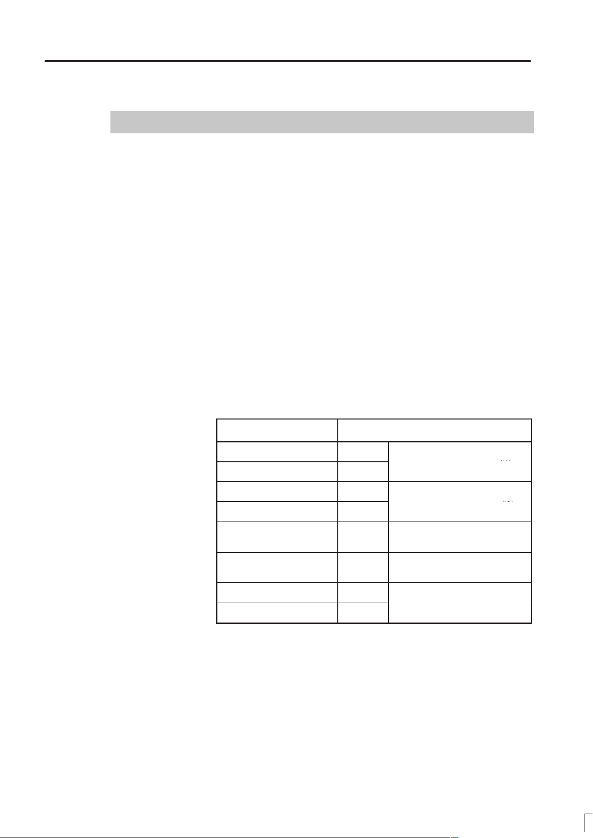
The models covered by this manual, and their abbreviations are :
Product name Abbreviations
FANUC Series 16–TC 16–TC
FANUC Series 160–TC 160–TC
FANUC Series 16–MC 16–MC
FANUC Series 160–MC 160–MC
FANUC Series 18–TC 18–TC
FANUC Series 180–TC 180–TC
FANUC Series 18–MC 18–MC
FANUC Series 180–MC 180–MC
*1)In the case of two–path control is added.
T series or
T series (two–path control)
M series or
M series (two–path control)
T series or
T series (two–path control)
T series or
T series (two–path control)
(*1)
(*1)
(*1)
(*1)
3
Page 17
1. GENERAL
GENERAL
B–62752EN/01
Manuals related to
Series 16–C
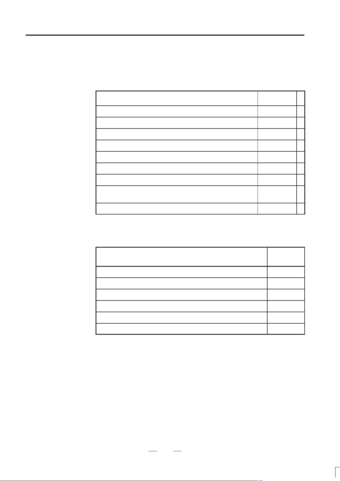
The table below lists manuals related to the FANUC Series
16/18/160/180 MODEL B. In the table, this manual is marked with an
asterisk (*).
Manuals Related to the Series 16/18/160/180–C
Manual name
DESCRIPTIONS B–62752EN *
CONNECTION MANUAL (HARDWARE) B–62753EN
CONNECTION MANUAL (FUNCTION) B–62753EN–1
OPERATOR’S MANUAL (For LATHE) B–62754EN
OPERATOR’S MANUAL (FOR MACHINING CENTER) B–62764EN
MAINTENANCE MANUAL B–62755EN
PARAMETER MANUAL B–62760EN
PROGRAMMING MANUAL
(Macro Compiler / Macro Executer)
FAPT MACRO COMPILER PROGRAMMING MANUAL B–66102E
Specification
number
B–61803E–1
Manuals related to
control motor α series
Manuals related to control motor α series
Manual name
FANUC AC SERVO MOTOR α series DESCRIPTIONS B–65142E
FANUC AC SERVO MOTOR α series PARAMETER MANUAL B–65150E
FANUC AC SPINDLE MOTOR α series DESCRIPTIONS B–65152E
FANUC AC SPINDLE MOTOR α series PARAMETER MANUAL B–65160E
FANUC CONTROL MOTOR AMPLIFIER α series DESCRIPTIONS B–65162E
FANUC CONTROL MOTOR α series MAINTENANCE MANUAL B–65165E
Specification
number
4
Page 18
B–62752EN/01
p
(
Controlled ath
Controlled axes (each ath)
Controllable axes ex ansion (total)
2
GENERAL
2. LIST OF SPECIFICATIONS
LIST OF SPECIFICATIONS
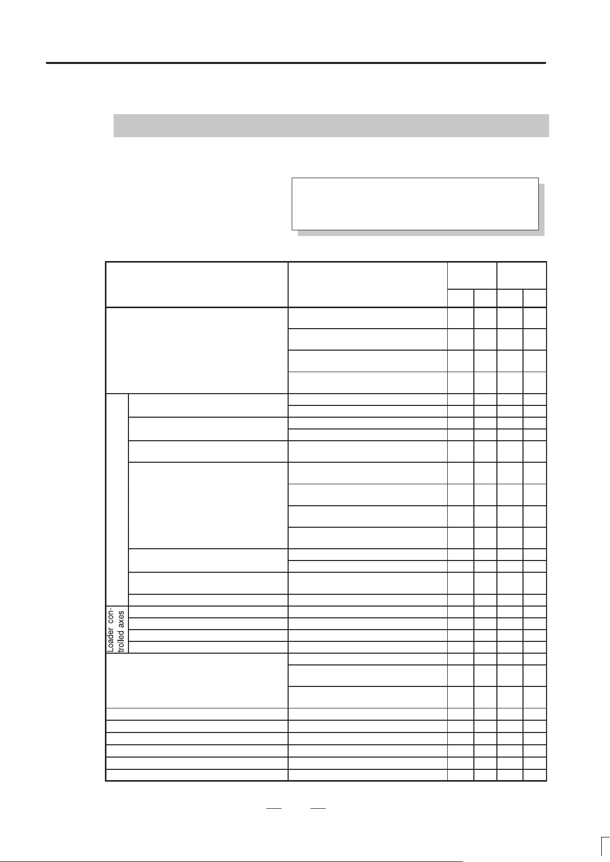
: Standard : Standard option : Option
: Function included in another option
Note) Some combinations of these options are restricted.
Axis control
Series 16
Item Specifications
Series 160
TC MC TC MC
12 axes (Machine 8 axes × 1–path +
Loader 4 axes)
Max. controlled axes
(Machine controlled axes + Loader controlled
axes)
(Machine controlled axes are including Cs axes)
p
p
Simultaneous controllable axes (each
path)
p
Machine controlled axes
Simultaneous controllable axes expansion
(total)
Axis control by PMC
Cs contouring control 1 axis for each axis
Controllable path 1–path
Controlled axes Max. 4 axes
Simultaneous controllable axes Max. 4 axes
Axis control by PMC Max. 4 axes
Axis name
Axis recomposition Only for 2–path — —
Simple synchronous control
Angular axis control
Arbitrary angular axis control
B axis control function — —
Tandem control
18 axes (Machine 7 axes × 2–path +
Loader 4 axes)
10 axes (machine 6 axes 1 path +
loader 4 axes)
14 axes (machine 5 axes 2 paths +
loader 4 axes)
1–path
2–path —
2 axes — —
3 axes — —
Simultaneous 2 axes
Max. 8 axes (for 1–path) (Including Cs
axis)
Max. 7 axes (for 2–path) (Feed 4 axes +
Cs axis)
Max. 6 axes (for 1–path) (including Cs
axis)
Max. 5 axes (for 2–path) (feed 4 axes +
Cs axis)
Max. 6 axes
Max. 4 axes — —
Max. simultaneous 4 axes per path (Not
available on Cs axis)
Optional from X, Y, Z, U, V, W, A, B, C — —
Optional from X, Y, Z, A, B, C in case of G
code system A
Optional from X, Y, Z, U, V, W, A, B, C in
case of G code system B/C
— —
— —
— —
— — —
— —
— —
— —
— — —
— —
— —
Series 18
Series 180
5
Page 19
2. LIST OF SPECIFICATIONS
p
GENRAL
B–62752EN/01
Series 18
Series 180
Item
Item
Specifications
Specifications
Series 16
Series 160
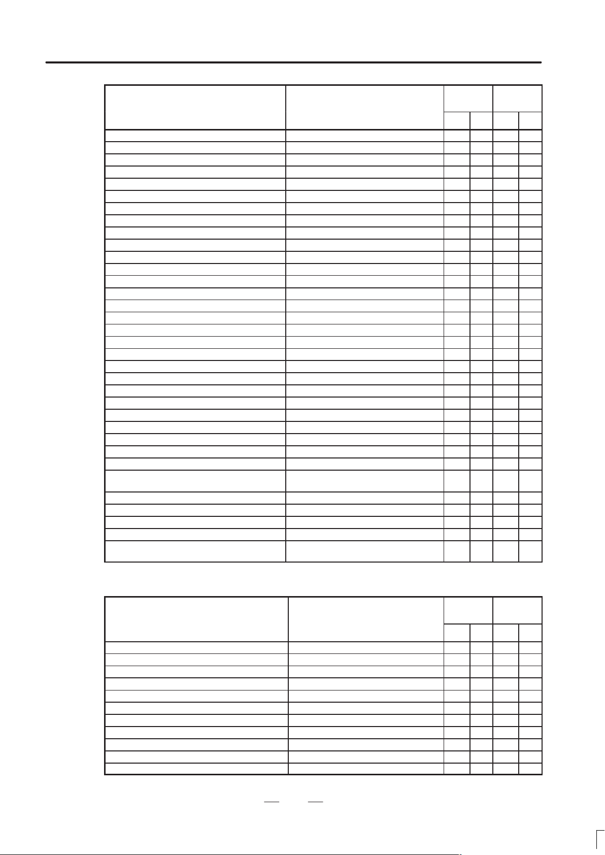
MCTCMCTC
Controlled axis detach
Chopping function — —
Simple electric gear box — —
Least input increment 0.001mm, 0.001deg, 0.0001inch
Increment system 1/10 0.0001mm, 0.0001deg, 0.00001inch
Flexible feed gear Optional DMR
Learning control
Preview repetitive control
Dual position feedback
Fine Acc & Dec control
HRV control
Inch/metric conversion
Interlock All axes / each axis / cutting block start
Machine lock All axes / each axis
Emergency stop
Overtravel
Stored stroke check 1
Stroke limit external setting — —
Stored stroke check 2 — —
Stored stroke check 3 — —
Stored stroke check 2, 3 — —
Stroke limit check before moving
Chuck & tail stock barrier — —
Mirror image Each axis
Follow–up
Servo–off / mechanical handle feed
Chamfering on/off — —
Backlash compensation
Backlash compensation for each rapid traverse
and cutting feed
Stored pitch error compensation
Straight compensation
Position switch
Tool post interference check Only for 2–path — —
Unexpected disturbance torque detection func-
tion
Operation
Series 16
Item Specifications
Series 160
TC MC TC MC
Automatic operation (memory)
DNC operation Reader/puncher interface is required.
MDI operation
Scheduling function Only for 1–path
Program number search
Sequence number search
Sequence number comparison and stop
Program restart
Tool retract & recover
Retreat and retry function — —
Buffer register
Series 18
Series 180
6
Page 20

B–62752EN/01
p
GENERAL
2. LIST OF SPECIFICATIONS
Series 16
Item
Item
Dry run
Single block
JOG feed
Manual reference position return
Reference position setting without DOG
Reference position setting with mechanical stop-
per
1 unit/each axis
Manual handle feed
Manual handle feed rate
Tool direction handle feed — —
Tool direction handle feed B Tool direction+normal direction — —
Manual handle interruption
Incremental feed ×1, ×10,×100, ×1000
Jog and handle simultaneous mode
Manual numerical command
Manual linear/circular interpolation Only for 1 path
2 units — —
2 units / 3 units — —
×1, ×10, ×m,×n
m
: 1 to 127, n : 0 to 1000
Specifications
Specifications
Series 160
Series 18
Series 180
Interpolation
Series 16
Item Specifications
Series 160
TC MC TC MC
Positioning
Single direction positioning G60 — —
Exact stop mode G61 — —
Exact stop G09 — —
Linear interpolation
Circular interpolation Multi–quadrant is possible
Exponential interpolation — —
Dwell
Polar coordinate interpolation
Cylindrical interpolation
Helical interpolation
Helical interpolation B
Involute interpolation — —
Hypothetical axis interpolation
Conical/spiral interpolation — —
Smooth interpolation High–precision contour control is required — — —
Thread cutting, synchronous cutting
Thread cutting retract — —
Continuous thread cutting — —
Variable lead thread cutting — —
Circular threading — —
Polygon turning — —
Polygon machining with two spindles — —
G00 (Linear interpolation type positioning
is possible)
Dwell in seconds and dwell in revolution
(In case of dwell in revolution for MB,
thread cutting, synchronous cutting option
is required)
Circular interpolation plus max. 2 axes
linear interpolation
Circular interpolation plus max. 4 axes
linear interpolation.
— — —
Series 18
Series 180
MCTCMCTC
7
Page 21

2. LIST OF SPECIFICATIONS
p
Ra id traverse
GENRAL
B–62752EN/01
Series 16
Item
Item
Skip function G31
High–speed skip function
Continuous high–speed skip — —
Multi–step skip function
Reference position return G28
Reference position return check G27
2nd reference position return
3rd/4th reference position return
Floating reference position return
Normal direction control — —
Continuous dressing For grinding machine — —
Infeed control For grinding machine — —
Balanced cutting Only for 2–path — —
Index table indexing — —
High speed cycle cutting Only for 1–path
Specifications
Specifications
Series 160
Series 18
Series 180
Feed function
Series 16
Item Specifications
Series 160
TC MC TC MC
p
Rapid traverse override F0, 25, 50, 100%
Feed per minute mm/min
Feed per revolution
Feed per revolution without position coder — —
Tangential speed constant control
Cutting feedrate clamp
Automatic acceleration/deceleration
Rapid traverse bell–shaped acceleration / decel-
eration
Linear acceleration/deceleration after cutting feed
interpolation
Bell–shaped acceleration/deceleration after cut-
ting feed
Linear acceleration/deceleration before cutting
feed interpolation
Feedrate override 0 to 254%
2nd feedrate override 0 to 254%
F1–digit feed — —
Inverse time feed — —
Jog override 0 to 655.34%
Override cancel
Manual feed per revolution — —
External deceleration
Feed stop
Advanced preview control — —
Simple high–precision contour control — —
High precision contour control 64–bit RISC only at 1–path control) — — —
Max. 240m/min (1µm)
Max. 100m/min (0.1µm)
Rapid traverse : linear
Cutting feed
Feed per minute only
: exponential function
Series 18
Series 180
MCTCMCTC
8
Page 22

B–62752EN/01
p
O tional block ski
Program number
Addition of work iece coordinate system air
G code system
GENERAL
2. LIST OF SPECIFICATIONS
Program input
Series 16
Item Specifications
Series 160
TC MC TC MC
Tape code EIA/ISO automatic recognition
Label skip
Parity check Horizontal and vertical parity
Control in/out
p
Max. programmable dimension ±8–digit
Sequence number N5–digit
Absolute/incremental programming Combined use in the same block
Decimal point input/pocket calculator type deci-
mal point input
Input unit 10 time multiply
Diameter/radius programming (X axis) — —
Plane selection G17, G18, G19
Rotary axis designation
Rotary axis roll over
Polar coordinate command — —
Coordinate system setting
Automatic coordinate system setting
Coordinate system shift — —
Direct input of coordinate system shift — —
Workpiece coordinate system G52 to G59
Workpiece coordinate system preset
Direct input of workpiece zero offset value measured
Manual absolute on/off
Direct drawing dimension programming — —
Chamfering / Corner R — —
Optional chamfering/corner R — —
Programmable data input G10
Sub program call 4 folds nested
Custom macro B
Addition of custom macro common variables #100 to #199, #500 to #999
Macro variables common between two paths For 2–path
Pattern data input
Interruption type custom macro
Canned cycles — —
Multiple repetitive cycles — —
Multiple repetitive cycles II Pocket profile — —
Canned cycles for drilling
Pecking drilling cycle for small diameter — —
Canned cycles for grinding For grinding cycle
Circular interpolation by R programming
Mirror image for double turret — —
Automatic corner override — —
p
p
p
1
9
O4–digit
O8–digit
48 pairs — —
300 pairs — —
A — —
B/C — —
Series 18
Series 180
9
Page 23

2. LIST OF SPECIFICATIONS
MMC–IV
p
p
GENRAL
B–62752EN/01
Series 16
Item
Item
Automatic corner deceleration — —
Feedrate clamp by circular radius — —
Scaling — —
Coordinate system rotation
3–dimensional coordinate system conversion — —
Programmable mirror image — —
Figure copying — —
Retrace function — —
Tape format for FS15
Conversional programming with graphic function Only for 1–path
Macro executer Max. 4MB
C language executer Max. 4MB
Using FANUC MMC–IV
–
Using Intelligent Terminal
Using High–speed Serial Bus and per-
sonal computer
Specifications
Specifications
Series 160
Series 18
Series 180
Conversational programming function for machining center
Series 16
Item Specifications
Series 160
TC MC TC MC
Super CAP II M — —
Super CAP M — —
NC format output function — —
C–axis conversational programming — —
Contour figure repetition function — —
Background graphic function — —
U–axis conversational function — —
CAP I — —
Series 18
Series 180
MCTCMCTC
Conversational programming function for lathe
Series 16
Item Specifications
Series 160
TC MC TC MC
Super CAP II T
Super CAP T
NC format output function — —
C–axis conversational programming — —
Y–axis conversational programming — —
P code macro variable 4000 — —
Back machining by sub–spindle — —
Chuck data expansion 60 — —
Tool/chuck workpiece interference check — —
T code offset pair expansion — —
CAP I For 1 path lathe — —
CAP II
Auxiliary machining function — —
Automatic process determination function — —
For 1–path lathe
For 2–path lathe
For 1–path lathe
For 2–path lathe
For 1–path lathe
For 2–path lathe
— —
— —
— —
Series 18
Series 180
10
Page 24
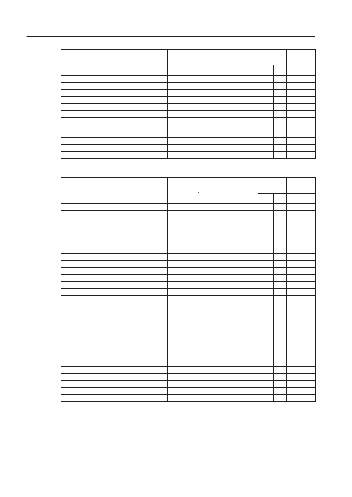
B–62752EN/01
p
GENERAL
2. LIST OF SPECIFICATIONS
Series 16
Item
Item
Automatic process determination function B — —
Animated simulation function — —
Animated simulation function for vertical lathe — —
C–axis FAPT function — —
Y–axis FAPT function — —
Back machining function — —
Balance cut FAPT function Only for 2–path — —
Conversational screen display language change
over
Sub memory addition — —
Registration of file name to floppy cassette — —
Symbolic CAP T — —
Specifications
Specifications
Series 160
— —
Series 18
Series 180
Auxiliary / Spindle function
Series 16
Item Specifications
Series 160
TC MC TC MC
Auxiliary function M8–digit
2nd auxiliary function B8–digit
Auxiliary function lock
High speed M, S, T interface
Waiting function Only for 2–path —
Multiple command of auxiliary function 3
M code group check
Spindle function S5–digit, binary output
Spindle serial output S5–digit, serial output
3rd spindle serial output Only for 1–path — —
Spindle analog output S5–digit, analog output
Constant surface speed control
Spindle override 0 to 254%
Actual spindle speed output — —
Spindle speed fluctuation detection
Analog voltage control by PMC
1st spindle orientation
1st spindle output switching function
2nd spindle orientation
2nd spindle output switching function
3rd spindle orientation — —
3rd spindle output switching function — —
Spindle synchronous control — —
Spindle simple synchronous control
Multi spindle control — —
Spindle positioning — —
Rigid tap
Rigid tapping by manual handle — —
Series 18
Series 180
MCTCMCTC
11
Page 25

2. LIST OF SPECIFICATIONS
p
Tool function
Addition of tool airs for tool life management
Tool function / Tool compensation
Tool offset
Tool offset memory B Geometry/wear memory — —
Tool offset memory C
Tool length compensation — —
Tool offset
Y–axis offset — —
Cutter cpmpensation B — —
Cutter compensation C — —
3–dimensional cutter compensation — —
Tool nose radius compensation — —
Tool geometry / wear compensation — —
Tool life management
p
Extended tool life management — —
Tool offset value counter input — —
Tool length measurement — —
Automatic tool length measurement — —
Automatic tool offset — —
Offset valne measuremet direct input — —
Offset valne measuremet direct inputI B — —
Wheel wear compensation — —
GENRAL
Item Specifications
T7+1 / T6+2 — —
T8 digits — —
±6 digits 32 — —
±6 digits 64 — —
±6 digits 99 — —
±6 digits 200 — —
±6 digits 400 — —
±6 digits 499 — —
±6 digits 999 — —
±6 digits 9/16 pairs — —
±6 digits 32 pairs — —
±6 digits 64 pairs — —
±6 digits 99 pairs — —
Distinction between geometry and wear,
or between cutter and tool length compensation
128 pairs — —
512 pairs — —
B–62752EN/01
Series 16
Series 160
Series 18
Series 180
TC MC TC MC
— —
12
Page 26
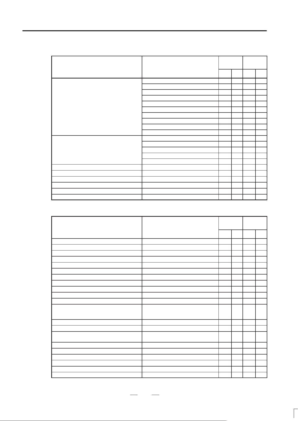
B–62752EN/01
p
Part rogram storage length
p
GENERAL
2. LIST OF SPECIFICATIONS
Editing operation
Series 16
Item Specifications
Series 160
TC MC TC MC
10m — —
20m
40m
80m
p
Registered programs
Part program editing
Program protect
Background editing
Extended part program editing
Playback
Machining time stamp function
160m
320m
640m
1280m
2560m — —
5120m — —
63
125
200
400
1000
Series 18
Series 180
Setting and display
Series 16
Item Specifications
Series 160
TC MC TC MC
Status display
Clock function
Current position display
Program display Program name 16 characters
Parameter setting and display
Self–diagnosis function
Alarm display
Alarm history display
Operator message history display
Operation history display
Help function
Reading mounted PCB data, reading data
Remote diagnostic function
Run hour and parts count display
Actual speed display
Display of spindle speed and T code at all
screens
Directory display of floppy cassette
Directory display nad punch for each group
Graphic display
Dynamic graphic display — —
Backgroud graphic function without CAP Option 2 board is required —
Optional path name display Only for 2–path —
displayed on CNC screen, and reading
internal status and alarm status, etc.
Series 18
Series 180
13
Page 27
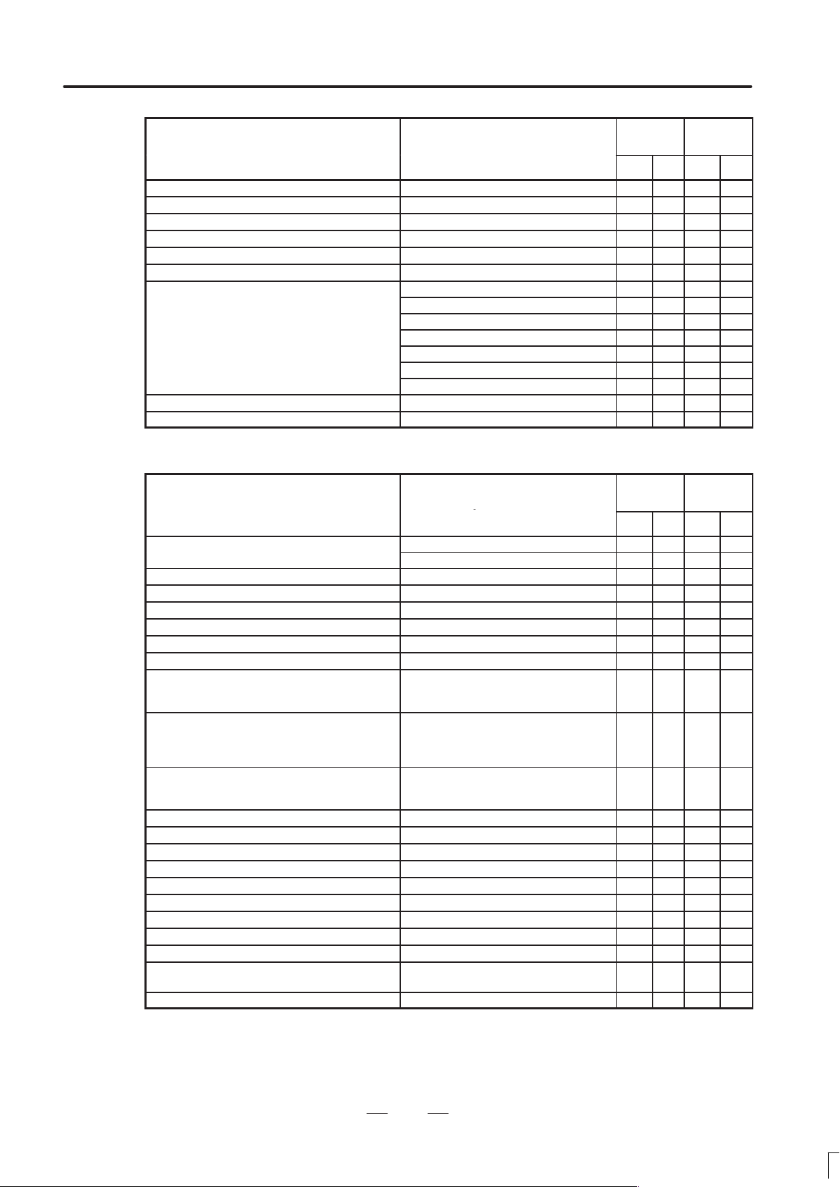
2. LIST OF SPECIFICATIONS
p
Reader/ uncher interface
GENRAL
B–62752EN/01
Series 16
Item
Item
Servo setting screen
Spindle setting screen Only for serial interface
Servo waveform display Graphic display circuit is required
Display of hardware and software configuration
Software operator’s panel
Software operator’s panel general purpose switch
English
Japanese (Chinese character)
German / French
Multi–language display
Data protection key 3 types
Erase CRT screen display
Italian
Chinese
Spanish
Korean
Specifications
Specifications
Series 160
Series 18
Series 180
Data input/output
Series 16
Item Specifications
Series 160
TC MC TC MC
p
Input/output simultaneous operation Only for 1–path — —
Remote buffer Only for 1–path
High–speed remote buffer A Only for 1–path
High–speed remote buffer B Only for 1–path — —
Data server Only for 1–path
External I/O device control
DNC1 control
DNC2 control
OSI–Ethernet
Analog input/output
External tool offset
External message
External machine zero point shift
External data input Including above 3 items
External workpiece number search 15
External program number search 1 to 9999
FANUC Handy File
FANUC FLOPPY CASSETTE
FANUC PROGRAM File Mate
Memory card interface For main tenance
Reader/puncher(Ch.1) interface
Reader/puncher(Ch.2) interface
Uploading/downloading a part program,
Reading/writing CNC data, Transfer of
PMC data, Memory operation control, etc.
Only for 1–path
Uploading/downloading a part program,
Reading/writing CNC data, Transfer of
PMC data, Memory operation control, etc.
Only for 1–path
IEEE802.3, 10BASE–5 or –2, ISO MMS
support, Each FA function
For data backup and user program loading
Series 18
Series 180
MCTCMCTC
14
Page 28
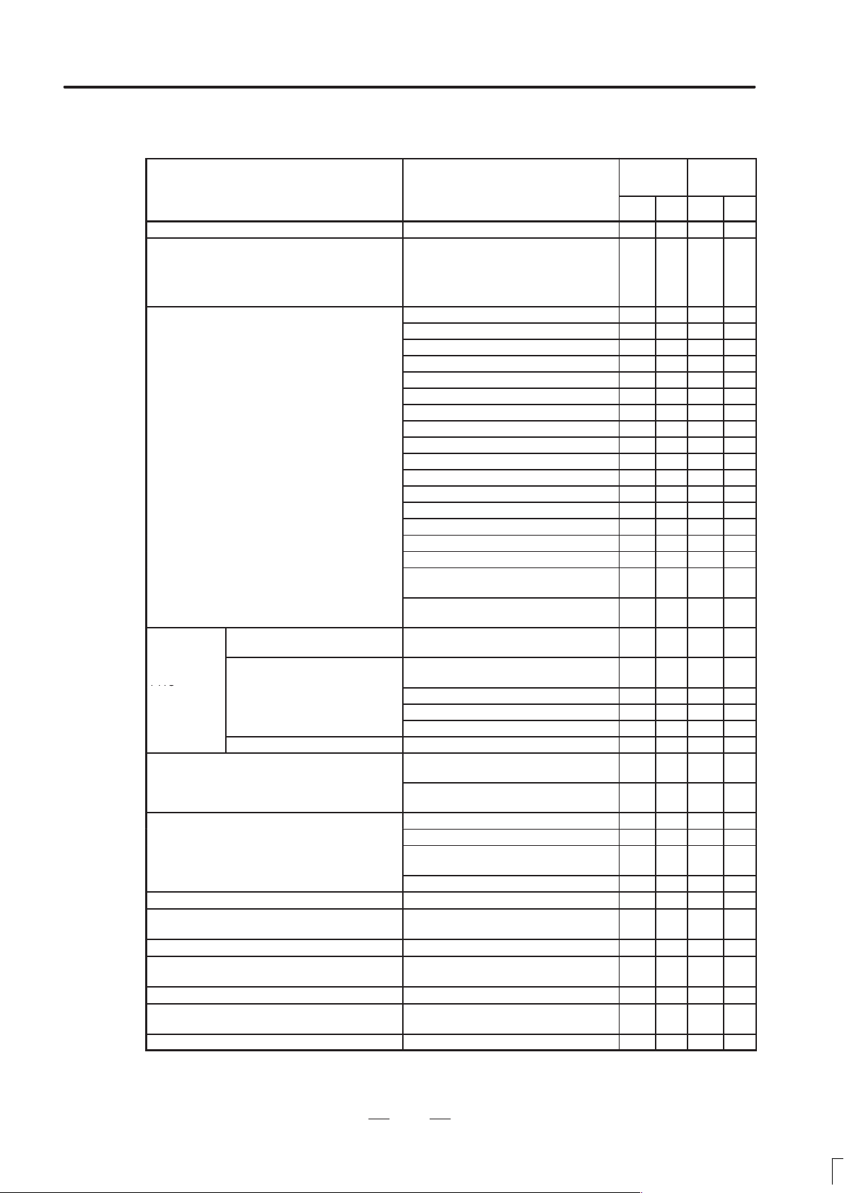
B–62752EN/01
p
Setting and dis lay unit
PMC
()
Machine interface (I/O Link)
GENERAL
2. LIST OF SPECIFICATIONS
Others
Series 16
Item Specifications
Series 160
TC MC TC MC
Abnormal load detection
NC ready, servo ready, automatic operation, automatic operation start lamp, feed
Status output signal
p
PMC–RB5/RB6
PMC
system
Machine interface (I/O Card)
(Available 1 or 2 card)
Max. DI/DO points : 1024/1024 points
Manual pulse generator
Pendant type manual pulse generator
Cordless type manual pulse generator Restricted use in Japan
Connectable servo motor
Connectable servo amp. FANUC control motor amplifier α series
Connectable position detector (for full–closed
control)
Connectable spindle motor FANUC AC spindle motor, etc.
PMC–RC3/RC4
Step sequence function Included in PMC–RB6/RC4
hold, reset, NC alarm, distribution end,
rewinding, inch input, cutting, inposition,
thread cutting, tapping, etc.
9”monochrome CRT/MDI(small size)
9”monochrome CRT/MDI(standard size)
9”monochrome PDP/MDI(standard size)
14”color CRT/MDI(horizontal type)
14”color CRT/MDI(vertical type)
9”monochrome CRT(separate type)
9”monochrome PDP(separate type)
7.2”monochrome LCD(separate type)
8.4”color LCD/MDI(small size)
8.4”color LCD/MDI(standard size)
8.4”color LCD(separate type)
9.5”color LCD/MDI(horizontal type)
9.5”color LCD/MDI(vertical type)
9.5”monochrome LCD(separate type)
Separate MDI(small size)
Separate MDI(standard size)
Separate MDI for 9.5”LCD
(standard size, horizontal type)
Separate MDI for 9.5”LCD
(standard size, vertical type)
Basic instruction : 1.0µs/step
Max. step number ladder
Basic instruction : 0.10µs/step
Max. step number ladder
C language : Max. 2MB
Nonvolatile memory expansion
Signal waveform display
Sink type output
Max. DI/DO points
Source type output B
Max. DI/DO points
I/O Unit MODEL A
I/O Unit MODEL B
Operator’s panel connection unit
Max. DI/DO points
Machine operator’s panel interface unit
With axis selection and magnification select switch
FANUC AC servo motor α series (with
serial interface pulse coder)
Pulse coder / optical scale (2–phase
pulse interface)
: 24000
: 24000
: 156/120
: 156/120
: 96/64
Series 18
Series 180
15
Page 29

2. LIST OF SPECIFICATIONS
Connectable spindle amp
Control unit
dimensions
GENRAL
B–62752EN/01
Item
Item
p
ISA Bus Expansion Borad Slot
Input power supply
p
.
2 slots 112(W) × 380(H) × 172(D) mm
3 slots 172(W)×380(H)×172(D) mm
4 slots 224(W)×380(H)×172(D) mm
6 slots 336(W)×380(H)×172(D) mm
8 slots 448(W)×380(H)×172(D) mm — —
Series 18
Series 180
Specifications
Specifications
Series 16
Series 160
MCTCMCTC
FANUC AC spindle amp. (serial interface
spindle amp.), etc.
Analog interface
FANUC control motor amplifier α series
Full size 3 slots
112(W) 380(H) 172(D)mm
24VDC "10%
200 to 240 VAC +10%, –15%
50 to 60Hz±3Hz
16
Page 30

II. NC FUNCTION
Page 31

B–62752EN/01
PREFACE
NC FUCNTION
PREFACE
This part describes the functions that can be performed on all models. For
the functions available with each model, see the list of specifications in
Part I.
In the description of this manual, the models are sometimes named as
follows:
M series : 16-MC, 18-MC, 160-MC, 180-MC
T series : 16-TC, 18-TC, 160-TC, 180-TC
19
Page 32

1. CONTROLLED AXES
CONTROLLED AXES
1
NC FUNCTION
B–62752EN/01
1.1
NUMBER OF THE ALL
CONTROLLED AXES
The number of all controlled axes is the sum of the number of machine
controlled axes and the number of loader controlled axes. The machine
controlled axes include Cs axis.
16–MC/16–TC/160–MC/160–TC (1–path)
: 12 axes (8 machine axes + 4 loader axes)
16–MC/16–TC/160–MC/160–TC (2–path)
: 18 axes (7 machine axes2 paths+4 loader axes)
18–MC/18–TC/180–MC/180–TC (1–path)
: 10 axes (6 machine axes + 4 loader axes)
18–TC/180–TC (2–path)
: 18 axes (5 machine axes2 paths+4 loader axes)
20
Page 33

B–62752EN/01
1.2
MACHINE CONTROLLED AXES
NC FUCNTION
1. CONTROLLED AXES
1.2.1
Number of Controlled Paths (T Series)
1.2.2
Number of Basic Controlled Axes
1.2.3
Number of Basic Simultaneously Controlled Axes
1.2.4
Number of Controlled Axes Expanded (All)
T wo–path control is available in 16–MC, 16–TC, and 18–TC.
In 18–MC, number of controlled paths is one.
16–MC/18–MC/160–MC/180–MC (each path) : 3 axes
16–TC/18–TC/160–TC/180–TC (each path) : 2 axes
16–MC/18–MC/160–MC/180–MC (each path) : 3 axes
16–TC/18–TC/160–TC/180–TC (each path) : 2 axes
16–MC/16–TC/160–MC/160–TC (1–path) : Max. 8 axes (including Cs axis)
16–MC/16–TC/160–MC/160–TC (2–path) : Max. 7 axes (6 feed axes + Cs
axis)
18–MC/18–TC/180–MC/180–TC (1–path) : Max. 6 axes (including Cs axis)
18–TC/180–TC (2–path) : Max. 5 axes (4 feed axes + Cs
axis)
1.2.5
Number of Simultaneously Controlled Axes Expanded (All)
1.2.6
Axis Control by PMC
1.2.7
Cs Contour Control
16–MC/16–TC/160–MC/160–TC (each path) : Max. 6 axes
18–MC/18–TC/180–MC/180–TC (each path) : Max. 4 axes
16–MC/16–TC/18–MC/18–TC/160–MC/160–TC/180–MC/180–TC (each
path)
: Max. simultaneous 4 axes (Cs axis is disable.)
16–MC/16–TC/18–MC/18–TC/160–MC/160–TC/180–MC/180–TC (each
path)
: 1 axis
21
Page 34

1. CONTROLLED AXES
NC FUNCTION
B–62752EN/01
1.3
LOADER CONTROLLED AXES
1.4
AXIS NAMES
Number of controlled paths : 1–path
Number of controlled axes : Max. 4 axes
Number of simultaneously controlled axes : Max. 4 axes
Number of controlled axes by PMC : Max. 4 axes
T series :
The two basic axes are always set to X and Z. Additional axes can be
selected from A, B, C, U, V, W, and Y freely. For the 16-TB (2–path
control), the two basic axes are always set to X and Z on each path, and
additional axes can be selected freely from A, B, C, U, V, W, and Y.
Notes
If U, V , or W is used as an axis name, the G code system
must be either B or C.
M series :
The three basic axes are set to X, Y, and Z. Additional axes can be
selected from A, B, C, U, V, and W freely.
For two–path control, X, Y, and Z are always used as the names of the
three basic axes. Additional axes can be assigned any of A, B, C, U,
V, and W as their names.
22
Page 35

B–62752EN/01
IS–B
IS–C
NC FUCNTION
1. CONTROLLED AXES
1.5
INCREMENT SYSTEM
Metric input 0.001 mm (radius programming) 0.001 mm
Inch input 0.0001 inch (radius programming) 0.001 mm
Millimeter
machine
There are two increment systems as shown in the tables below . One of the
increment systems can be selected using a parameter.
Notes
If IS-C is selected, option ”increment system 1/10” is
required.
Table 1.5(a) IS–B
Least
Least input increment
0.001 mm (diameter programming) 0.0005 mm
0.001 deg 0.001 deg
0.0001 inch (diameter programming) 0.0005 mm
0.001 deg 0.001 deg
0.001 mm (diameter programming) 0.00005 inch
command
increment
Abbreviation
–
Millimeter
machine
Metric input 0.001 mm (radius programming) 0.0001 inch
0.001 deg 0.001 deg
0.0001 inch (diameter programming) 0.00005 inch
Inch input 0.0001 inch (radius programming) 0.0001 inch
0.001 deg 0.001 deg
Table 1.5(b) IS–C
Least
Least input increment
0.0001 mm (diameter programming) 0.00005 mm
Metric input 0.0001 mm (radius programming) 0.0001 mm
0.0001 deg 0.0001 deg
0.00001 inch (diameter programming) 0.00005 mm
Inch input 0.00001 inch (radius programming) 0.0001 mm
0.0001 deg 0.0001 deg
0.0001 mm (diameter programming) 0.000005 inch
Metric input 0.0001 mm (radius programming) 0.00001 inch
command
increment
Abbreviation
–
Millimeter
machine
0.0001 deg 0.0001 deg
0.00001 inch (diameter programming) 0.000005 inch
Inch input 0.00001 inch (radius programming) 0.00001 inch
0.0001 deg 0.0001 deg
23
Page 36

1. CONTROLLED AXES
IS–B
IS–C
NC FUNCTION
B–62752EN/01
The least command increment is in millimeters or inches, depending on
the machine tool. One of them must be selected using a parameter
beforehand.
The least input increment can be switched between metric input and inch
input by using a G code (G20 or G21) or a setting parameter.
1.5.1
Input Unit (10 Times)
1.6
MAXIMUM STROKE
The following least input increments can be set using a parameter:
Increment system Least input increment
IS–B 0.01 mm, 0.01 deg, or 0.001 inch
IS–C 0.001 mm, 0.001 deg, or 0.0001 deg
The following table lists the maximum strokes of machine tools that are
allowed by the control unit:
Maximum stroke = Least command increment 99999999
Increment system Maximum stroke
Millimeter machine
–
Inch machine
Millimeter machine
–
Inch machine
±99999.999 mm
±99999.999 deg
±9999.9999 inch
±99999.999 deg
±9999.9999 mm
±9999.9999 deg
±999.99999 inch
±9999.9999 deg
Notes
1 The values (in mm or inches) in the table are diameter
values if diameter programming is specified, or radius
values if radius programming is specified.
2 A command that exceeds the maximum stroke is not
allowed.
24
Page 37

B–62752EN/01
2
NC FUCNTION
PREPARATORY FUNCTIONS
2. PREP ARATORY FUNCTIONS
25
Page 38

2. PREP ARATORY FUNCTIONS
Group
Function
01
06
09
08
01
NC FUNCTION
B–62752EN/01
2.1
T SERIES
A B C
G00 G00 G00 Positioning (Rapid traverse)
G01 G01 G01
G02 G02 G02
G03 G03 G03 Circular interpolation CCW or Helical interpolation CCW
G04 G04 G04 Dwell
G05 G05 G05 High speed cycle cutting
G07.1
(G107)
G10 G10 G10 Programmable data input
G11 G11 G11 Programmable data input mode cancel
G12.1
(G112)
G13.1
(G113)
G code
G07.1
(G107)
G12.1
(G112)
G13.1
(G113)
G07.1
(G107)
G12.1
(G112)
G13.1
(G113)
The following G codes are provided. The G codes are classified into
three: A, B, and C. One of the G code types can be selected using a
parameter. In this manual, G code system B is assumed.
G code list for T series (1/3)
Linear interpolation (Cutting feed)
Circular interpolation CW or Helical interpolation CW
00
21
Cylindrical interpolation
Polar coordinate interpolation mode
Polar coordinate interpolation cancel mode
G17 G17 G17 XpYp plane selection
G18 G18 G18 16 ZpXp plane selection
G19 G19 G19 YpZp plane selection
G20 G20 G70
G21 G21 G71
G22 G22 G22
G23 G23 G23
G25 G25 G25
G26 G26 G26
G27 G27 G27 Reference position return check
G28 G28 G28 Return to reference position
G30 G30 G30 00 2nd, 3rd and 4th reference position return
G30.1 G30.1 G30.1 Floating reference point return
G31 G31 G31 Skip function
G32 G33 G33
G34 G34 G34
G36 G36 G36 Automatic tool compensation X
Input in inch
Input in mm
Stored stroke check function on
Stored stroke check function off
Spindle speed fluctuation detection off
Spindle speed fluctuation detection on
Thread cutting
V ariable–lead thread cutting
G37 G37 G37 00 Automatic tool compensation Z
G39 G39 G39 Corner circular interpolation
26
Page 39

B–62752EN/01
Group
Function
00
20
00
14
12
NC FUCNTION
2. PREP ARATORY FUNCTIONS
G code list for T series (2/3)
G code
A B C
G40 G40 G40 Tool nose radius compensation cancel
G41 G41 G41 07 Tool nose radius compensation left
G42 G42 G42 Tool nose radius compensation right
G50 G92 G92
G50.3 G92.1 G92.1
G50.2
(G250)
G51.2
(G251)
G52 G52 G52
G53 G53 G53
G54 G54 G54 Workpiece coordinate system 1 selection
G55 G55 G55
G56 G56 G56
G57 G57 G57
G58 G58 G58 Workpiece coordinate system 5 selection
G59 G59 G59 Workpiece coordinate system 6 selection
G65 G65 G65 00 Macro calling
G66 G66 G66
G67 G67 G67
G68 G68 G68 Mirror image for double turrets ON or balance cut mode
G69 G69 G69
G50.2
(G250)
G51.2
(G251)
G50.2
(G250)
G51.2
(G251)
04
Coordinate system setting or max. spindle speed setting
Workpiece coordinate system preset
Polygonal turning cancel
Polygonal turning
Local coordinate system setting
Machine coordinate system setting
Workpiece coordinate system 2 selection
Workpiece coordinate system 3 selection
Workpiece coordinate system 4 selection
Macro modal call
Macro modal call cancel
Mirror image for double turrets OFF or balance cut mode
cancel
G70 G70 G72 Finishing cycle
G71 G71 G73 Stock removal in turning
G72 G72 G74
G73 G73 G75 Pattern repeating
G74 G74 G76 End face peck drilling
G75 G75 G77 Outer diameter/internal diameter drilling
G76 G76 G78 Multiple threading cycle
G71 G71 G72 Traverse grinding cycle (for grinding machine)
G72 G72 G73
G73 G73 G74 Oscilation grinding cycle (for grinding machine)
G74 G74 G75
00
01
Stock removal in facing
Traverse direct constant–dimension grinding cycle
(for grinding machine)
Oscilation direct constant–dimension grinding cycle
(for grinding machine)
27
Page 40

2. PREP ARATORY FUNCTIONS
Group
Function
02
05
03
11
G code
A B C
G80 G80 G80 Canned cycle for drilling cancel
G83 G83 G83 Cycle for face drilling
G84 G84 G84 Cycle for face tapping
G86 G86 G86 10 Cycle for face boring
G87 G87 G87 Cycle for side drilling
G88 G88 G88 Cycle for side tapping
G89 G89 G89 Cycle for side boring
G90 G77 G20 Outer diameter/internal diameter cutting cycle
G92 G78 G21 01 Thread cutting cycle
G94 G79 G24 Endface turning cycle
NC FUNCTION
G code list for T series (3/3)
B–62752EN/01
G96 G96 G96
G97 G97 G97
G98 G94 G94
G99 G95 G95
* G90 G90
* G91 G91
* G98 G98
* G99 G99
Constant surface speed control
Constant surface speed control cancel
Per minute feed
Per revolution feed
Absolute programming
Incremental programming
Return to initial level (See Explanations 6)
Return to R point level (See Explanations 6)
28
Page 41

B–62752EN/01
00
25
17
06
04
24
00
NC FUCNTION
2. PREP ARATORY FUNCTIONS
2.2
M SERIES
The following G codes are provided :
G code list for M series (1/3)
G code Group Function
G00
G01
01
G02 Circular interpolation/Helical interpolation CW
G03 Circular interpolation/Helical interpolation CCW
G04 Dwell, Exact stop
G05 High speed cycle machining
G07.1 (G107) Cylindrical interpolation
G08
G09
G10 Programmable data input
G10.6 Tool retract and recover
G11 Programmable data input mode cancel
Positioning
Linear interpolation
Look–ahead control
Exact stop
G12.1
G13.1
G15
17
G16
G17
G18 02
G19 Y pZp plane selection Zp: Z axis or its parallel axis
G20
G21
G22
4
G23
G25
G26
G27 Reference position return check
G28 Return to reference position
G29
Polar coordinate interpolation mode
Polar coordinate interpolation cancel mode
Polar coordinates command cancel
Polar coordinates command
XpY p plane selection Xp: X axis or its parallel axis
ZpXp plane selection Yp: Y axis or its parallel axis
Input in inch
Input in mm
Stored stroke check function on
Stored stroke check function off
Spindle speed fluctuation detection off
Spindle speed fluctuation detection on
Return from reference position
G30
G30.1 Floating reference point return
G31 Skip function
G33 01 Thread cutting
2nd, 3rd and 4th reference position return
29
Page 42

2. PREP ARATORY FUNCTIONS
00
08
00
11
22
00
15
G code Group Function
NC FUNCTION
G code list for M series (2/3)
B–62752EN/01
G37
G39
G40
G41
G42 Cutter compensation right
G40.1 (G150) Normal direction control cancel mode
G41.1 (G151) 19 Normal direction control left side on
G42.1 (G152) Normal direction control right side on
G43
G44
G45 Tool offset increase
G46
G47
G48 Tool offset double decrease
G49
G50
G51
07
08 Tool length compensation cancel
11
Automatic tool length measurment
Corner offset circular interpolation
Cutter compensation cancel
Cutter compensation left
Tool length compensation + direction
Tool length compensation – direction
Tool offset decrease
Tool offset double increase
Scaling cancel
Scaling
G50.1
22
G51.1
G52
G53
G54
G54.1 Additional workpiece coordinate system selection
G55 Workpiece coordinate system 2 selection
G56
G57 Workpiece coordinate system 4 selection
G58 Workpiece coordinate system 5 selection
G59 Workpiece coordinate system 6 selection
G60 00 Single direction positioning
G61 Exact stop mode
G62
G63
G64
14
Programmable mirror image cancel
Programmable mirror image
Local coordinate system setting
Machine coordinate system selection
Workpiece coordinate system 1 selection
Workpiece coordinate system 3 selection
Automatic corner override
Tapping mode
Cutting mode
30
Page 43

B–62752EN/01
12
16
09
09
03
05
13
10
20
NC FUCNTION
2. PREP ARATORY FUNCTIONS
G code list for M series (3/3)
G code Group Function
G65 00 Macro call
G66
G67
G68
G69
G73
G74
G75 01 Plunge grinding cycle (for grinding machine)
G76 09 Fine boring cycle
G77 Direct constant–dimension plunge grinding cycle(for grinding machine)
G78 01 Continuous–feed surface grinding cycle(for grinding machine)
G79 Intermittent–feed surface grinding cycle(for grinding machine)
G80
G81 Drilling cycle, spot boring cycle or external operation function
G82 Drilling cycle or counter boring cycle
G83 Peck drilling cycle
G84
G85
Macro modal call
Macro modal call cancel
Coordinate rotation
Coordinate rotation cancel
Peck drilling cycle
Counter tapping cycle
Canned cycle cancel/external operation function cancel
Tapping cycle
Boring cycle
G86 Boring cycle
G87 Back boring cycle
G88 Boring cycle
G89 Boring cycle
G90
G91
G92 00 Setting for work coordinate system or clamp at maximum spindle speed
G94
G95
G96
G97
G98
1
G99
G160
2
G161
Absolute command
Increment command
Feed per minute
Feed per rotation
Constant surface speed control
Constant surface speed control cancel
Return to initial point in canned cycle
Return to R point in canned cycle
In–feed control function cancel(for grinding machine)
In–feed control function(for grinding machine)
31
Page 44

3. INTERPOLA TION FUNCTIONS
INTERPOLATION FUNCTIONS
3
NC FUNCTION
B–62752EN/01
32
Page 45

B–62752EN/01
NC FUCNTION
3. INTERPOLA TION FUNCTIONS
3.1
POSITIONING (G00)
Positioning is done with each axis separately (Non linear interpolation
type positioning).
Either of the following tool paths can be selected accroding to bit 1 of
parameter No. 1401.
Non linear interpolation positioning
The tool is positioned with the rapid traverse rate for each axis
separately. The tool path is normally straight.
Linear interpolation posioning
The tool path is the same as in linear interpolation (G01). The tool is
positioned within the shortest possible time at a speed that is not more
than the rapid traverse rate for each axis.
Linear interpolation
positioning
End position
Start position
Non linear interpolation
positioning
It is decelerated, to a stop at the end point, and imposition check is
performed (checks whether the machine has come to the specified
position). The in-position check can be suppressed using a parameter.
Width of imposition can be set as a parameter.
Format
G00 _ ;
33
Page 46

3. INTERPOLA TION FUNCTIONS
NC FUNCTION
B–62752EN/01
3.2
M series
SINGLE DIRECTION POSITIONING (G60)
(M SERIES)
Format
It is always controlled to perform positioning to the end point from a
single direction, for better precision in positioning. If direction from start
point to end point is different from the predecided direction, it once
positions to a point past the end point, and the positioning is reperformed
for that point to the end point.
Even if the direction from start point to end point is the same as predecided
direction, the tool stops once before the end point.
Exceeded
amount
End point
G60 _ ;
Temporary stop
34
Page 47

B–62752EN/01
NC FUCNTION
3. INTERPOLA TION FUNCTIONS
3.3
LINEAR
INTERPOLATION
(G01)
Format
Linear interpolation is done with tangential direction feed rate specified
by the F code.
X axis
End point
(200, 150)
(Program example)
G01 G90 X200. Z150. F200 ;
Start point
Z axis
G01 _ F_ ;
F : Feedrate
35
Page 48

3. INTERPOLA TION FUNCTIONS
NC FUNCTION
B–62752EN/01
3.4
CIRCULAR
INTERPOLATION
(G02, G03)
Circular interpolation of optional angle from 0° to 360° can be specified.
G02: Clockwise (CW) circular interpolation
G03: Counterclockwise (CCW) circular interpolation
Yp
G03
G02
G17
Xp
Xp
G02
G18
G03
Zp
Zp
G03
G02
Yp
G19
Feed rate of the tangential direction takes the speed specified by the F
code. Planes to perform circular interpolation is specified by G17, G18,
G19. Circular interpolation can be performed not only on the X, Y, and
Z axis but also on the parallel axes of the X, Y, and Z axes.
G17: Xp-Yp plane
G18: Zp-Xp plane
G19: Yp-Zp plane
where
Xp: X axis or its parallel axis
Yp: Y axis or its parallel axis
Zp: Z axis or its parallel axis
Parameter is set to decide which parallel axis of the X, Y, Z axes to be the
additional axis.
Format
Arc on the Xp-Yp plane
G17
Arc on the Zp-Xp plane
G18
Arc on the Yp-Zp plane
G19
I_. J_, K_:Distance of the X, Y, Z axes from the start point to the center of
the circle
R:Arc radius (For an arc having a central angle of 180° or greater, specify
an R value with a minus sign. A complete circumference cannot be specified.)
Y
X
Center
G02
G03
G02
G03
G02
G03
(x, y)
i
Xp_ Yp_
Zp_ Xp_
Yp_ Zp_
X
Start
point
j
Z
Center
R_
I_ J_
R_
K_ I_
R_
J_ K_
(z, x)
k
F_ ;
F_ ;
F_ ;
Start
point
i
Z
Y
Center
(y, z)
j
Start
point
k
36
Page 49

B–62752EN/01
NC FUCNTION
3. INTERPOLA TION FUNCTIONS
3.5
HELICAL
INTERPOLATION
(G02, G03)
Helical interpolation performs circular interpolation of a maximum of
two axes, synchronizing with other optional two axes circular
interpolation. Thread cutting of large radius threads or machining of solid
cams are possible by moving a tool in a spiral.
The commanded speed is the speed of the tangential direction of the arc.
Thus, the speed of a linear axis is expressed as follows:
Lengthoflinearaxis
F
Arclength
Z
Tool path
X
Tangential speed along an arc by circular interpolation
is the rate specified in programming.
Y
Format
Arc on the Xp-Yp plane
G17
Arc on the Zp-Xp plane
G18
Arc on the Yp-Zp plane
G19
α, β: Optional axis other than the circular interpolation axes
G02
G03
G02
G03
G02
G03
Xp_ Yp_
Zp_ Xp_
Yp_ Zp_
R_
I_ J_
R_
K_ I_
R_
J_ K_
α_ (β_) F_ ;
α_ (β_) F_ ;
α_ (β_) F_ ;
37
Page 50

3. INTERPOLA TION FUNCTIONS
NC FUNCTION
B–62752EN/01
3.6
POLAR COORDINA TE
INTERPOLA TION
(G12.1, G13.1)
Format
Explanations
Polar coordinate
interpolation mode
(G12.1)
The function in which contour control is done in converting the command
programmed in a cartesian coordinate system to the movement of a linear
axis (movement of a tool) and the movement of a rotary axis (rotation of
a workpiece) is the polar coordinate interpolation. It is an effective
function when a straight line groove is cut on the outer diameter of a
workpiece or when a cam shaft is ground.
Whether the polar coordinate interpolation is done or not is commanded
by a G code.
These G codes shall be commanded in a single block.
G12.1; Polar coordinate interpolation mode
(Polar coordinate interpolation shall be done.)
G13.1; Polar coordinate interpolation cancel mode
(Polar coordinate interpolation is not done.)
The axes (linear axis and rotary axis) on which polar coordinate
interpolation is done are set beforehand by parameters.
Change the mode to polar coordinate interpolation mode by commanding
G12.1, and a plane (hereinafter referred to as polar coordinate
interpolation plane) is selected in which linear axis is made to the first
axis of the plane, and virtual axis being a right angle with the linear axis
is made to the second axis of the plane. Polar coordinate interpolation is
carried out on this plane.
In the polar coordinate interpolation made, the command of linear
interpolation (G01) and circular interpolation (G02, G03) is possible.
And both absolute command (G90) and incremental command (G91) are
possible.
For the program command it is possible to apply cutter compensation.
For the path after cutter compensation is done, polar coordinate
interpolation can be made.
As for feedrate, specify the tangential speed (relative speed between the
workpiece and the tool) on the polar coordinate interpolation plane
(cartesian coordinate system) with F.
Polar coordinate
interpolation cancel
mode (G13.1)
The polar coordinate interpolation cancel mode is obtained by G13.1
command.
38
Page 51

B–62752EN/01
Examples
Polar coordinate
interpolation by X axis
(Linear axis) and C axis
(Rotary axis)
NC FUCNTION
C (Virtual axis)
3. INTERPOLA TION FUNCTIONS
C axis
N204
N205
N206
(X axis is diameter programming and C axis is radius programming)
00001;
:
N100 G90 G00 X120.0 C0 Z_ ;
N200 G12.1;
N201 G42 G01 X40.0 F D01;
N202 C10.0;
N203 G03 X20.0 C20.0 R10.0 ;
N204 G01 X-40.0 ;
N205 G-10.0 ;
N206 G03 X-20.0 C-20.0 I10.0 K0 ;
N207 G01 X40.0 ;
N208 C0 ;
N209 G40 X120.0 ;
N210 G13.1 ;
N300 Z_ ;
N400 X_ C_ ;
:
M30 ;
N203
N202
N208
N207
Positioning to the starting position
Starting polar coordinate interpolation
Contour program
(Program in cartesian coordinate
system of X-C plane)
Canceling polar coordinate
interpolation
Path after cutter
compensation
N201
Programmed path
N200
Tool
X axis
Z axis
39
Page 52

3. INTERPOLA TION FUNCTIONS
NC FUNCTION
B–62752EN/01
3.7
CYLINDRICAL
INTERPOLATION
(G07.1)
Format
Explanations
Cylindrical interpolation
mode
When the form on the expanded side view of a cylinder (from on the
cylinder coordinate system) is commanded by a program command, the
NC converts the form into a linear axis movement and a rotary axis
movement then performs a contour control. This feature is called the
cylindrical interpolation.
Cylindrical interpolation is commanded with G07.1.
G07.1 (Name of rotary axis) Radius value of cylinder ;
Cylindrical interpolation mode
G07.1 (Name of rotary axis) 0 ;
Cancellation mode of cylindrical interpolation
Cylindrical interpolation is made between the rotary axis specified in the
block of G07.1 and the other optional linear axis.
Circle interpolation command is allowed as well as linear interpolation,
during cylindrical interpolation mode. Also, absolute command and
incremental command can be made. Cutter compensation can be added
to the program command. Cylindrical interpolation is made for the path
after cutter compensation.
Feed rate gives the tangential speed on the expanded plane of the cylinder
with F.
Cancellation mode of
cylindrical interpolation
G07.1 (Name of rotary axis) 0; Cancellation mode of cylindrical
interpolation is made when commanded as above.
40
Page 53

B–62752EN/01
NC FUCNTION
3. INTERPOLA TION FUNCTIONS
Examples
Z
mm
N05
120
110
90
70
60
N06
N07
N08
An example of a program
O0001 (CYLINDRICAL INTERPOLATION);
N1 G00 G00 Z100.0 C0;
N2 G01 G18 Z0 C0;
N3 G7.1 C57299;
N4 G01 G42 Z120.0 D10 F250;
N5 G40.0;
N6 G02 Z90.0 C60.0 R30.0 ;
N7 G01 Z70.0;
N8 G03 Z60.0 C70.0 R10.0;
N9 G01 C150.0;
N10 G03 Z70.0 C190.0 R75.0;
N11 G01 Z110.0 C230.0;
N12 G02 Z120.0 C270.0 R75.0;
N13 G01 G360.0;
N14 G40 Z100.0;
N15 G07.1 C0;
N16
M30;
N12
N11
N09
N10
C
Z
N13
R
deg
C
0
30
60 70
150
230190
270
360
41
Page 54

3. INTERPOLA TION FUNCTIONS
NC FUNCTION
B–62752EN/01
3.8
M series
INVOLUTE
INTERPOLATION
(G02.2, G03.2)
(M SERIES)
Format
With the following command, the involute curve machining can be
performed. Approximate involute curve with a minute straight line or arc
is not needed. Therefore, the programming becomes simple and reduces
the tape length. The distribution of the pulse will not be interrupted
during the continuous minute block high speed operation, so fast, smooth
involute curve machining is possible.
Start point
(I, J)
R
Basic
circle
Clockwise involute
interpolation
Xp–Y p plane
End point
(X, Y)
End point
(X, Y)
R
Basic
circle
Counterclockwise involute
interpolation
Start point
(I, J)
G17
Zp–Xp plane
G18 Zp_ Xp_ K_ I_ R_ F_ ;
Yp–Zp plane
G19 Yp_ Zp_ J_ K_ R_ F_ ;
G02.2 : Clockwise involute interpolation
G03.2 : Counterclockwise involute interpolation
Xp, Y p, Zp : End point coordinate value
I, J, K : Distance to the center of the basic circle of the involute
R : Radius of basic circle
F : Cutting feedrate
G02.2
G03.2
G02.2
G03.2
G02.2
G03.2
Xp_ Yp_ I_ J_ R_ F_ ;
curve from start point
42
Page 55

B–62752EN/01
NC FUCNTION
3. INTERPOLA TION FUNCTIONS
3.9
M series
EXPONENTIAL
FUNCTION
INTERPOLATION
(G02.3, G03.3)
(M SERIES)
In synchronization with the travel of the rotary axis, the linear axis (X
axis) performes the exponential function interpolation. With the other
axes, the linear interpolation the X axis is performed.
This function is effective for the tapered constant helix machining in the
tool grinding machine.
This function is the best for the fluting with the end mill etc. and grinding.
X (Linear axis)
∆X
A (Rotary axis)
∆A
Tapered constant helix machining
I
B
r
J
U
X
Z
A
X
43
Page 56

3. INTERPOLA TION FUNCTIONS
Format
NC FUNCTION
Positive rotation (ω=0)
B–62752EN/01
G02.3 X_Y_ Z_ I_ J_ K_ R_ F_ Q_ ;
Negative rotation (ω=1)
G03.3 X_Y_ Z_ I_ J_ K_ R_ F_ Q_ ;
X_ : Command terminal point by Absolute or incremental
Y_ : Command terminal point by Absolute or incremental
Z_ : Command terminal point by Absolute or incremental
I_ : Command of angle I (The command unit is 0.001 deg.
The range of command is 1 to ±89deg)
J_ : Command of angle J (The command unit is 0.001 deg.
The range of command is 1 to ±89deg)
K_ : Amount of division of the linear axis in the exponential function
interpolation (amount of span). The command range is a
positive value.)
R_ : Command of constant value R in the exponential function
interpolation.
F_ : Command of initial feed rate.
The command is the same as the normal F code. The feed rate
shall be given by the synthesized speed including the rotary
axis.
Q_ : Command of feed rate at terminal point.
The command unit is based on the reference axis. Within the
CNC, the tool is interpolated between the initial feed rate (F_)
and final feed rate (Q_) depending on the amount of linear axis
travel.
Explanations
The exponential function relation expression between the linear axis and
the rotary axis is defined as in the following :
X() + R (e
–1)
K
A() + (–1) 360
K=
ω=0 or 1
R, I, J are constant and θ is the angle (radian) of rotation.
Also from the equation (1),
(X) + K ȏn {
X tan(I)
1
tan(I)
2
R
Travel of linear axis (1). . . . .
Travel of rotation axis (2). . . . .
) 1}
Thus, when the tool moves from X1 to X2 along the linear axis, the angle
moved about the rotation axis is calculated as follows:
+ K {ȏn (
X2 tan(I)
R
) 1) *ȏn (
X1 tan(I)
R
) 1) }
Specify formulas (1) and (2) in commands using the format described
above.
44
Page 57

B–62752EN/01
NC FUCNTION
3. INTERPOLA TION FUNCTIONS
3.10
M series
SMOOTH
INTERPOLATION
(G05.1) (M SERIES)
Examples
Either of two types of machining can be selected, depending on the
program command.
For those portions where the accuracy of the figure is critical, such as
at corners, machining is performed exactly as specified by the program
command.
For those portions having a large radius of curvature where a smooth
figure must becreated, points along the machining path are
interpolated with a smooth curve, calculated from the polygonal lines
specified with the program command (smooth interpolation).
In smooth interpolation mode, the CNC automatically determines,
according to the program command, whether an accurate figure is
required, such as at corners, or a smooth figure is required where the
radius of curvature is large. If a block specifies a travel distance or
direction which differs greatly from that in the preceding block, smooth
interpolation is not performed for that block. Linear interpolation is
performed exactly as specified by the program command. Programming
is thus very simple.
Interpolated by smooth curve
N1
Linear interpolation
N1
N17
N2
N17
N2
N16
N16
N15
N14
N3
N3
N4
Interpolated by smooth curve
N15
N14
N4
N13
N5
N13
N5
N6
N6
N12
N12
N7
N7
N11
N8
N8
N10
N9
Linear interpolation
N11
N10
N9
Smooth interpolation can be specified in high–speed contour control
mode (between G05 P10000 and G05 P0). For details of high–speed
contour control, see Section 20.6.
Format
Starting of smooth interpolation mode
G05.1 Q2X0Y0Z0;
Cancelation of smooth interpolation mode
G05.1 Q 0φ;
45
Page 58

3. INTERPOLA TION FUNCTIONS
NC FUNCTION
B–62752EN/01
3.11
HYPOTHETICAL AXIS
INTERPOLATION
(G07)
In helical interpolation, when pulses are distributed with one of the
circular interpolation axes set to a hypothetical axis, sine interpolation is
enable.
When one of the circular interpolation axes is set to a hypothetical axis,
pulse distribution causes the speed of movement along the remaining axis
to change sinusoidally. If the major axis for threading (the axis along
which the machine travels the longest distance) is set to a hypothetical
axis, threading with a fractional lead is enabled. The axis to be set as the
hypothetical axis is specified with G07.
Y
r
0
2
2
1
Z
Format
G07 0; Hypothetical axis setting
G07 1; Hypothetical axis cancel
Where, is any one of the addresses of the controlled axes.
46
Page 59

B–62752EN/01
4
THREAD CUTTING
NC FUCNTION
4. THREAD CUTTING
47
Page 60

4. THREAD CUTTING
NC FUNCTION
B–62752EN/01
4.1
EQUAL LEAD
THREAD CUTTING
(G33)
SYSTEM A: G32)
Format
(WITH G CODE
By feeding the tool synchronizing with the spindle rotation, thread
cutting of the specified lead is performed. In addition to straight threads,
taper threads and scroll threads can be cut with equal leads.
L
Straight thread
L
L
T aper thread
Scroll thread
Explanations
G33 _ F_ :
F_ : Lead along the long axis
(axis having the largest amount of travel)
To form a single thread, threading is generally performed several times
from rough machining to finish machining along the same path.
Threading starts when the one-revolution signal from the position coder
attached to the spindle is detected. So threading always starts at the same
point on the circumference of the workpiece, and threading is performed
along the same path on the workpiece. In this case, however, the shaft
must rotate at a constant speed during operations from rough machining
to finish machining. If the spindle speed changes, an accurate thread may
not be produced.
The following shows the specifiable lead range:
M series
Metric input F1 to F50000 (0.01 to 500.00mm)
Inch input F1 to F99999 (0.0001 to 9.9999inch)
T series
Metric input 0.0001 to 500.0000mm
Specifiable lead range
Specifiable lead range
Inch input 0.000001 to 9.999999inch
Notes
Leads exceeding the maximum cutting feed speed when
converted to per minute feed speed cannot be specified.
48
Page 61

B–62752EN/01
NC FUCNTION
4. THREAD CUTTING
4.2
T series
MULTIPLE–THREAD
CUTTING (G33)
Format
Multiple–thread screws
Constant–lead threading
G33 _ F_ Q_ ;
G33 _ Q_ ;
_ : End point
F_ : Lead in longitudinal direction
Q_ : Threading start angle
49
Page 62

4. THREAD CUTTING
NC FUNCTION
B–62752EN/01
4.3
T series
VARIABLE LEAD THREAD CUTTING (G34) (T SERIES)
Format
Variable lead thread cutting can be done by commanding long axis
direction lead and lead increase/decrease per spindle rotation.
G34 _ F_ K_ :
Metric input ±0.0001 to ±500.0000 mm/rev
Inch input ±0.000001 to ±9.999999 inch/re
F_ : Long axis direction lead at start point
K_ : Lead increase/decrease per spindle rotation
Command value range of
lead increase/decrease (K) per spindle rotation:
4.4
T series
CONTINUOUS THREAD CUTTING
(T SERIES)
Continuous thread cutting in which thread cutting command block is
continuously commanded is available. As it is controlled so that the
spindle synchronism shift (occurred when shifting from one block to
another) is kept to a minimum, special threads like threads which leads
or shape change during the cycle can also be cut.
G33
G33
G33
50
Page 63

B–62752EN/01
NC FUCNTION
4. THREAD CUTTING
4.5
CIRCULAR THREADING (G35, G36) (T
SERIES)
Format
T series
Using the G35 and G36 commands, a circular thread, having the specified
lead in the direction of the major axis, can be machined.
L
Circular thread
G35
G36
G35 : Clockwise circular threading command
G36 : Counterclockwise circular threading command
X (U) : Specify the arc end point (in the same way as for G02,
Z (W)
X (U) _ Z (W) _ F _ Q _
G03).
I _ K _
R _ _ _
I, K : Specify the arc center relative to the start point, using
relative coordinates (in the same way as for G02, G03).
R : Specify the arc radius.
F : Specify the lead in the direction of the major axis.
Q : Specify the shift of the threading start angle (0 to 360°
in units of 0.001°)
51
Page 64

5. FEED FUNCTIONS
FEED FUNCTIONS
5
NC FUNCTION
B–62752EN/01
52
Page 65

B–62752EN/01
NC FUCNTION
5. FEED FUNCTIONS
5.1
RAPID TRAVERSE
Positioning of each axis is done in rapid motion by the positioning
command (G00).
There is no need to program rapid traverse rate, because the rates are set
in the parameter (per axis).
Least command increment Rapid traverse rate range
0.001mm, deg 30 to 240000mm/min, deg/min
0.0001mm, deg 30 to 100000mm/min, deg/min
0.0001inch 3.0 to 9600.0inch/min
0.00001inch 3.0 to 4000.0inch/min
Notes
The above feed rates are limits according to the NC’s
interpolation capacity when the high-resolution detection
interface is equipped. When the whole system is
considered, there are also limits according to the servo
system. For details, refer to Appendix A.
53
Page 66

5. FEED FUNCTIONS
NC FUNCTION
B–62752EN/01
5.2
CUTTING FEED RATE
5.2.1
Tangential Speed Constant Control
5.2.2
Cutting Feed Rate Clamp
5.2.3
Per Minute Feed (G94)
Feed rates of linear interpolation (G01), and circular interpolation (G02,
G03) are commanded with numbers after the F code.
In cutting feed, it is controlled so that speed of the tangential direction is
always the same commanded speed.
Cutting feed rate upper limit can be set as parameters. If the actual cutting
feed rate (feed rate with override) is commanded exceeding the upper
limit, it is clamped to a speed not exceeding the upper limit.
With the per minute feed mode G94, tool feed rate per minute is directly
commanded by numerical value after F.
Least command increment Cutting feed rate range
0.001mm, deg 1 to 240000mm/min, deg/min
0.0001mm, deg 1 to 100000mm/min, deg/min
0.0001inch 0.01 to 9600.0inch/min
0.00001inch 0.01 to 4000.0inch/min
Notes
The above feed rates are limits according to the NC’s
interpolation capacity when the high-revolution detection
interface is equipped. When the whole system is
considered, there are also limits according to the servo
system. For details, see Appendix A.
54
Page 67

B–62752EN/01
NC FUCNTION
5. FEED FUNCTIONS
5.2.4
Per Revolution Feed (G95)
M series
T series
With the per revolution feed mode G95, tool feed rate per revolution of
the spindle is directly commanded by numeral after F. A position coder
must be mounted on the spindle.
For the T series, however, the feed–per–revolution command can be
enabled by setting the corresponding parameter accordingly, even when
the position coder is not installed (feed per revolution without position
coder).
Least command increment Cutting feed rate range
0.001mm, deg 0.01 to 500.00mm/rev, deg/rev
0.0001mm, deg 0.01 to 500.00mm/rev, deg/rev
0.0001inch 0.0001 to 9.9999inch/rev
0.00001inch 0.0001 to 9.9999inch/rev
Least command increment Cutting feed rate range
0.001mm, deg 0.0001 to 500.0000mm/rev, deg/rev
0.0001mm, deg 0.0001 to 500.0000mm/rev, deg/rev
0.0001inch 0.000001 to 9.999999inch/rev
0.00001inch 0.000001 to 9.999999inch/rev
5.2.5
M series
Inverse Time Feed (G93) (M Series)
5.2.6
M series
F1–digit Feed (M
Series)
Notes
The above feed rates are limits according to the NC’s
interpolation capacity. When the whole system is
considered there are also limits according to the servo
system. For details, See Appendix A.
Inverse time feed mode is commanded by G93, and inverse time by F
code. Inverse time is commanded with the following value in a 1/min
unit.
In linear interpolation F= Speed/distance
In circular interpolation F= Speed/radius
When F0 is commanded, alarm occurs.
When a 1-digit number from 1 to 9 is commanded after the F, the preset
speed corresponding the 1-digit number commanded is set as feed rate.
When F0 is commanded, rapid traverse is set.
Set the F1-digit feed rate change input signal on from the machine side,
and rotate the manual pulse generator. Feed rate of the currently selected
speed can be changed.
Feed rate set or changed will be memorized even after power is turned
off.
55
Page 68

5. FEED FUNCTIONS
5.3
OVERRIDE
NC FUNCTION
B–62752EN/01
5.3.1
Feed Rate Override
5.3.2
Second Feed Rate Override
5.3.3
Rapid Traverse Override
The per minute feed (G94) and per rotation feed (G95) can be overrided
by:
0 to 254% (per every 1%).
In inverse time, feed rate converted to per minute feed is overridden. Feed
rate override cannot be performed to F1-digit feed.
Feed rate also cannot be performed to functions as thread cutting and
tapping in which override is inhibited.
Cutting feed rate can be overrided by:
0 to 254% (per every 1%)
A second override can be performed on feed rats once overrided.
No override can be performed on functions as thread cutting and tapping
in which override is inhibited.
This function is used for controlling feed rate in adaptive control, etc.
Rapid traverse rate can be overridden by:
F0, 25%, 50%, 100%.
F0: A constant speed per axis can be set by parameter
An override of 0% to 100% can be applied in 1% steps using a signal.
5.3.4
Override Cancel
5.3.5
Jog Override
Feed rate override and the second feed rate override can be clamped to
100% by a signal from the machine side.
The manual continuous feedrate and incremental feed rate can be
overridden by:
0% to 655.34% (in steps of 0.01%)
56
Page 69

B–62752EN/01
NC FUCNTION
5. FEED FUNCTIONS
5.4
AUTOMATIC ACCELERATION/ DECELERATION
Acceleration and deceleration is performed when starting and ending
movement, resulting in smooth start and stop.
Automatic acceleration/deceleration is also performed when feed rate
changes, so change in speed is also smoothly done.
Rapid traverse : Linear acceleration/deceleration
(time constant is parameter set per axis)
Cutting feed : Exponential acceleration/deceleration
(time constant is parameter set per axis)
Jogging : Exponential acceleration/deceleration
(time constant is parameter set per axis)
Rapid traverse
F
R
0
T
R
Jog feed
F
C
: Rapid traverse
F
R
TR: Acceleration/
deceleration time
constant
T
Time
R
:Feed rate
F
C
T
: Acceleration/
C
deceleration time
constant
0
T
C
Feed, Dry run
F
J
0
T
J
T
C
FJ : Jog feed rate
TJ : Jog feed time
FL : Low feed rate after
F
L
T
J
Time
constant
deceleration
Time
57
Page 70

5. FEED FUNCTIONS
NC FUNCTION
B–62752EN/01
5.5
RAPID TRAVERSE
BELL–SHAPED
ACCELERATION/
DECELERATION
The function for rapid traverse bell–shaped acceleration/deceleration
increases or decreases the rapid traverse feedrate smoothly.
This reduces the shock to the machine system due to changing
acceleration when the feedrate is changed.
As compared with linear acceleration/deceleration, bell–shaped
acceleration/deceleration allows smaller time constants to be set,
reducing the time required for acceleration/deceleration.
Linear acceleration/deceleration
for rapid traverse
Feedrate
0
Time
Acceleration
0
Time
Bell–shaped acceleration/
deceleration for rapid traverse
Feedrate
0
Time
Acceleration
0
Time
58
Page 71

B–62752EN/01
5.6
LINEAR ACCELERATION/ DECELERATION AFTER CUTTING FEED INTERPOLATION
NC FUCNTION
Speed
5. FEED FUNCTIONS
T
C
T
C
Time
In the linear acceleration/deceleration, the delay for the command caused
by the acceleration/ deceleration becomes 1/2 compared with that in
exponential acceleration/deceleration, substantially reducing the time
required for acceleration and deceleration.
Also, the radius direction error in the circular interpolation caused by the
acceleration/deceleration is substantially reduced.
Z
∆r
∆r: Maximum value of radius
Command
path
Actual
path
r
Z
error (mm)
v : Feedrate (mm/sec)
r : Circular radius (mm)
: Acceleration/
T
1
deceleration time
constant (sec)
: Time constant of servo
T
2
motor (sec)
The maximum value of error in this radius direction is obtained
approximately by the following equation.
r + (
r + (
1
2
24
2
1
T
)
1
2
2
1
T
)
1
2
2
V
T
)
2
r
2
2
V
1
T
)
2
r
2
For exponential acceleration/deceleration. . . . .
For linear acceleration/deceleration after . . . . .
cutting feed interpolation
Consequently, in case of the linear acceleration/deceleration after
interpolation, if an error caused by the servo loop time constant is
excluded, the radius directional error will be reduced to 1/12, compared
with the exponential acceleration/deceleration.
59
Page 72

5. FEED FUNCTIONS
5.7
NC FUNCTION
B–62752EN/01
BELL–SHAPED
ACCELERATION/
DECELERATION
AFTER CUTTING
FEED
INTERPOLATION
Feedrate
B
Time
T
C
F/2
F
A
0
/2
T
C
T
C
As shown above in the quadratic curve, it is possible to accelerate and
decelerate the cutting feedrate.
When the acceleration and deceleration section are connected, the
composed curve shapes just like a hanging bell. That is why this kind of
acceleration/deceleration is called bell–shaped acceleration/deceleration.
Considering a time constant as T c (time spent to accelerate from feedrate
0 up to commanded feedrate F or time spent to decelerate from
commanded feedrate F down to feedrate 0), feedrate accelerates up to 1/2
of the commanded feedrate (F/2) for 1/2 of the time constant (T c/2). The
acceleration/deceleration curve 0A shown in the figure above can be
expressed by the following equation :
2F
f(t) +
2
t
2
T
C
The curve AB and 0A are symmetric with respect to point A.
The feature of this acceleration/deceleration is that the feedrate change is
small near feedrate 0 and the commanded feedrate.
60
Page 73

B–62752EN/01
NC FUCNTION
5. FEED FUNCTIONS
5.8
LINEAR ACCELERATION/ DECELERATION BEFORE CUTTING FEED INTERPOLATION
Exponential
acceleration/deceleration
after cutting feed
interpolation
Interpolation
f
(pulse distribution)
In response to the cutting feed command , the feedrate before
interpolation, the command feedrate can be directly accelerated/
decelerated. This enables a machined shape error caused by the delay of
acceleration/deceleration to be eliminated.
f
tt
Acceleration/
deceleration control
T
C
Servo
control
Motor
Linear acceleration/
deceleration after cutting
feed interpolation
f
Linear acceleration/
deceleration before
cutting feed interpolation
Acceleration/deceleration applied to
feedrate command
Interpolation
(pulse distribution)
f
Servo
t
T
C
Interpolation (Pulse destribution)
f
T
C
T
C
T
C
t
t
control
Servo
control
Motor
Motor
61
Page 74

5. FEED FUNCTIONS
NC FUNCTION
B–62752EN/01
5.9
T series
ERROR DETECTION
(T SERIES)
Generally, the CNC does not zero the feedrate at the interface of two
blocks during cutting feed.
Because of this, a corner of a tool path may be rounded.
This part causes the corner of the tool
path to be rounded.
Time
Programmed tool path
Actual tool–center path
If the error detect signal is used, it is possible to specify that a
block not be started until the acceleration/deceleration of the
previous block has been completed.
Notes
If the error detect signal is on, a cutting block is not executed
until the acceleration/deceleration of the previous cutting
block has been completed.
This function alone cannot prevent corner rounding due to
delay caused by the servo motor, however.
To prevent corner rounding due to delay caused by the
servo motor, use the in–position check function together
with this function.
After acceleration/
deceleration
Range od in–position check
After servo motor delay
Time
Time
62
Page 75

B–62752EN/01
NC FUCNTION
5. FEED FUNCTIONS
5.10
M series
EXACT STOP (G09)
(M SERIES)
5.11
M series
EXACT STOP MODE (G61) (M SERIES)
Move command in blocks commanded with G09 decelerates at the end
point, and in–position check is performed. G09 command is not
necessary for deceleration at the end point for positioning (G00) and
in–position check is also done automatically . This function is used when
sharp edges are required for workpiece corners in cutting feed.
Exact stop off
Exact stop on (The in-position
check is performed at the end of
a block.)
When G61 is commanded, deceleration of cutting feed command at the
end point and in–position check is performed per block thereafter. This
G61 is valid till G64 (cutting mode), G62 (automatic corner override), or
G63 (tapping mode) is commanded.
5.12
M series
CUTTING MODE (G64)
(M SERIES)
5.13
M series
T APPING MODE (G63)
(M SERIES)
5.14
M series
AUTOMATIC CORNER OVERRIDE (G62)
(M SERIES)
When G64 is commanded, deceleration at the end point of each block
thereafter is not performed and cutting goes on to the next block. This
command is valid till G61 (exact stop mode), G62 (automatic corner
override), or G63 (tapping mode) is commanded.
When G63 is commanded, feed rate override is ignored (always regarded
as 100%), and feed hold also becomes invalid. Cutting feed does not
decelerate at the end of block to transfer to the next block. And in-tapping
signal is issued during tapping operation. This G63 is valid till G61
(exact stop mode), G62 (automatic corner override), or G64 (cutting
mode) is commanded.
When G62 is commanded during cutter compensation, cutting feed rate
is automatically overridden at corner. The cutting quantity per unit time
of the corner is thus controlled not to increase. This G62 is valid till G61
(exact stop mode), G64 (cutting mode), or G63 (tapping mode) is
commanded.
63
Page 76

5. FEED FUNCTIONS
NC FUNCTION
B–62752EN/01
5.15
DWELL (G04)
Format
With the G04 command, shifting to the next block can be delayed.
When commanded with a per minute feed mode (G94), shifting to the next
block can be delayed for the commanded minutes.
When commanded with a per rotation feed mode (G95), shifting to the
next block can be delayed till the spindle rotates for the commanded
times.
Dwell may always be performed by time irrespective of G94 and G95 by
parameter selection.
Per second dwell
G94 G04
P_ or X_ : Dwell time commanded in seconds (0.001-99999.999 sec)
Per revolution dwell
G95 G04
P_ or X_ : Spindle rotation angle commanded in rev.
P_
;
X_
P_
;
X_
(0.001-99999.999 rev)
64
Page 77

B–62752EN/01
6
NC FUCNTION
REFERENCE POSITION
6. REFERENCE POSITION
65
Page 78

6. REFERENCE POSITION
NC FUNCTION
B–62752EN/01
6.1
MANUAL REFERENCE POSITION RETURN
6.2
SETTING
THE REFERENCE
POSITION WITHOUT
DOGS
Explanations
Setting the reference
position
Reference position
return
Positioning to the reference position can be done by manual operation.
With jogging mode (JOG), manual reference position return (ZRN)
signals, and signal for selecting manual reference position return axis (±J1
to ±J8) on, the tool the machine is turned on, it decelerates, and when it
is turned off again, it stops at the first grid point, and reference position
return end signal is output. This point is the reference position.
By performing manual reference position return, the machine coordinate
system and the work coordinate system is established.
There is only one method available to perform manual reference point
return:
In the grid method, a certain grid of the position detection is appointed as
the reference position. The reference position position can be shifted by
the grid shift function.
This function moves the machine to around the reference position set for
each axis in the manual continuous feed mode. Then it sets the reference
position for the machine in the manual reference position return mode
without the deceleration signal for reference position return. With this
function, the machine reference position can be set at a given position
without the deceleration signal for reference position return.
1 Place the machine in the manual continuous feed mode, and perform
positioning to a position near but not exceeding the reference position
from reference position return direction (setting by parameter).
2 Enter the manual reference position return mode, then input the feed
axis direction select signal (+) or (–) for the axis.
3 Positioning is made at the grid point located nearest from the current
point to reference position return direction. This point is recorded as
the reference position. If the absolute-position detector is provided,
the set reference position is retained after the power is turned off. In
this case, when the power is turned on again, there is no need for setting
the reference position again.
1 After the reference position is set, when the feed axis select signal (+)
or (–) is input for the axis in the reference position return mode,
reference position return operation is performed in rapid traverse
regardless of which signal (+) or (–) is input.
66
Page 79

B–62752EN/01
6.3
AUTOMATIC
REFERENCE
POSITION RETURN
(G28, G29(ONLY FOR
M SERIES ))
NC FUCNTION
6. REFERENCE POSITION
Return to reference
position (G28)
Return from reference
position (G29)
(M series)
With the G28 command, the commanded axis is positioned to the
reference position via the commanded point. After positioning, the
reference position return end lamp lights. If G28 was commanded when
reference position return is not performed after power on, reference
position return is done in the same sequence as the manual reference
position return.
G28 _ ;
: Command intermediate point
With the G29 command, the commanded axis is positioned to the point
commanded by G29, via the intermediate point commanded by G28.
G29 _ ;
Y
B
A
Intermediate
point
Reference position
R
Suppose tool change
was performed at R.
The programmer
need not calculate a
concrete movement
value between the
intermediate point
and the reference
position
C
.
Example of Use of G28 and G29
67
X
Page 80

6. REFERENCE POSITION
NC FUNCTION
B–62752EN/01
6.4
REFERENCE POSITION RETURN CHECK (G27)
Format
6.5
2ND, 3RD AND 4TH
REFERENCE
POSITION RETURN
(G30)
This function is used to check whether the reference position return
command was performed correctly.
When G27 is commanded, the commanded axis is positioned to the
specified position, reference position return end signal is output if
reference position return is performed to the correct position, and alarm
arises it is not positioned correctly to the reference point.
This function is available after power is turned on an reference point
return is performed.
G27 _ ;
With the G30 command, the commanded axis is positioned to the 2nd,
3rd, or the 4th reference position, via the commanded point. 2nd, 3rd, or
4th reference position return end signal is output when positioning ends.
Set the 2nd, 3rd, and 4th reference position position as parameters.
This function is available after power is turned on and reference position
return is performed.
G29 can be used to return from the 2nd, 3rd, and 4th reference point (same
as reference position return, G28) (M series only).
This function can be used once reference position return has been
performed after power–on.
Format
G30
P2
P3
P4
P2, P3, P4: Select from 2nd, 3rd, or 4th reference positions.
_ ;
If not selected, 2nd reference position return is
automatically selected.
68
Page 81

B–62752EN/01
NC FUCNTION
6. REFERENCE POSITION
6.6
FLOATING REFERENCE POSITION RETURN (G30.1)
It is possible to return the tool to the floating reference position by
commanding the G30.1.
The floating reference position is located on the machine and can be a
reference position of some sort of machine operation. It is not always a
fixed position but may vary in some cases. The floating reference
position can be set using the soft keys of MDI and can be memorized even
if the power is turned off.
Generally, the position where the tools can be replaced on machining
center, milling machine is a set position on top of the machinery. The
tools cannot be replaced at any machine angle. Normally the tool
replacement position is at any of the No. 1 to No. 4 reference position.
The tool can be restored to these positions easily by G30 command.
However, depending on the machine, the tools can be replaced at any
position as long as it does not contact the work piece.
In lathes, the tool can generally be changed at any position unless it
touches the workpiece or tailstock.
For machinery such as these, in order to reduce the cycle time, it is
advantageous to replace tools at a position as close as possible to the work.
For this purpose, tool replacement position must be changed for each
work shape and this feature can be easily realized by this function.
Namely , the tool replacement position which is suitable for works can be
memorized as the floating reference position and it is possible to return
the tool to the tool replacement position easily by commanding the
G30.1.
Format
Explanations
Examples
G30.1 _ ;
: It is the intermediate point to the floating reference position and is
commanded by an absolute value or an incremental value.
When the G30.1 is commanded, the axis commanded is set to the
intermediate point with rapid traverse at first and then is set to the floating
reference position from the intermediate point with rapid traverse. The
positioning to the intermediate point or to the floating point is performed
at rapid traverse for each axis (non-linear positioning). The floating
reference position return completion signal is output after completing the
floating reference position return.
G30.1 G90 X50.0 Y40.0 ;
Y
Intermediate point (50, 40)
Floating reference position
69
Workpiece
X
Page 82

6. REFERENCE POSITION
NC FUNCTION
B–62752EN/01
6.7
REFERENCE POSITION SHIFT
6.8
BUTT–TYPE
REFERENCE
POSITION SETTING
For reference position return using the grid method, you can shift the
reference position without having to move the deceleration dog, simply
by setting the amount of shift in a parameter.
The time required to adjust the reference position is thus greatly reduced
because the deceleration dog need not be adjusted.
Direction of reference
L
Deceleration dog
Grid point
: Reference position shift
L
SFT
: Distance the tool moves between the deceleration dog being
L
DEC
turned off and the first grid point encountered subsequently
(grid point when the reference position shift is 0)
(L
DEC
DEC
is displayed on the diagnostic screen.)
L
SFT
position return
Machine
zero point
The butt–type reference position setting function automates the setting of
a reference position by butting the tool against a mechanical stopper on
an axis. This function is provided to eliminate the variations in reference
position setting that arise when the procedure is performed by different
operators, and to minimize the amount of work involved in making fine
adjustments after reference position setting.
Select the axis for which the reference position is to be set, then perform
cycle start. The following operations are performed automatically:
1. The torque (force) of the selected axis is reduced so that the butting
feedrate is constant. The tool is butted against the mechanical stopper.
Then, the tool is drawn back a parameter–set amount from the
mechanical stopper.
2. Again, the torque (force) of the selected axis is reduced, then the tool
is butted against the mechanical stopper. Then, the tool is drawn back
a parameter–set amount from the mechanical stopper.
3. The point on the axis to which the tool is drawn back is set as the
reference position.
70
Page 83

B–62752EN/01
7
NC FUCNTION
COORDINATE SYSTEMS
By teaching the CNC the position the tool is to arrive, the CNC moves
the tool to that position. The position is specified using coordinates on a
certain coordinate system.
There are three types of coordinate systems.
Machine coordinate system
Workpiece coordinate system
Local coordinate system
As necessary , one of the above coordinate systems is used for specifying
coordinates for the target position of the tool.
7. COORDINA TE SYSTEMS
71
Page 84

7. COORDINA TE SYSTEMS
NC FUNCTION
B–62752EN/01
7.1
MACHINE COORDINATE SYSTEM (G53)
Format
Machine coordinate system is a coordinate system set with a zero point
proper to the machine system.
A coordinate system in which the reference point becomes the
parameter-preset coordinate value when manual reference point return is
performed, is set. With G53 command, the machine coordinate system
is selected and the axis is able to be moved in rapid traverse to the position
expressed by the machine coordinates.
G53 _ ;
72
Page 85

B–62752EN/01
NC FUCNTION
7. COORDINA TE SYSTEMS
7.2
WORKPIECE COORDINATE SYSTEM
7.2.1
Setting a Workpiece
Coordinate System
(Using G92)
(with G Code System A:
G50)
A coordinate system in which the zero point is set to a fixed point on the
workpiece, to make programming simple.
A workpiece coordinate system may be set by using one of the following
methods:
(1) Using G92 (G50 for G code system A)
(2) Using G54 to G59
When method (1) is used, a workpiece coordinate system is established
by programming a numeric value following G92.
When method (2) is used, six workpiece coordinate systems must be set
on the CR T/MDI panel in advance. A programmed command G54 to G59
is then used to select one of the six workpiece coordinate systems.
Format
Examples
Example 1
(G90) G92 _ ;
By using the above command, a workpiece coordinate system can be set
so that the current tool position is at a specified position.
T seriesM series
23.0
Z
X
0
25.2
X
375.1
φ128.7
Start
point
Z
G92 X25.2 Z23.0 ;
73
Reference point
G92 128.7 Z375.1 ;
(diameter programming)
Page 86

7. COORDINA TE SYSTEMS
NC FUNCTION
B–62752EN/01
Example 2
Set the reference point on the tool holder or turret as shown in the figure
below, then specify G92 at the beginning of the program. By specifying
an absolute command in this condition, the reference point is moved to
a specified position. To move the tool tip to a specified position,
compensate the distance between the reference point and the tool tip by
using tool length compensation (for the M system) or tool offset (for the
T system).
Reference
point
1200.0
0
G92 600.0 Z1200.0 ;
Setting the start point at a given
reference point on the tool holder
600.0
T seriesM series
700.0
Start point
= reference
position
φ1200.0
Z
X
G92 1200.0Z700.0 ;
(diameter programming)
Setting the start point at a given reference
point on the turret
Example 3
(Shift of a workpiece
coordinate system)
Format
T series
When a new workpiece coordinate system is created by specifying G92,
it is determined so that a given point on the tool has a given coordinate
value. So, there is no need to be concerned with old workpiece coordinate
systems. Particularly when the start point for machining is determined
based on the workpiece, the G92 command is useful. In this case, a desired
coordinate system can newly be created even if an old workpiece
coordinate system is invalid.
A workpiece coordinate system can be shifted by using the following
command:
When this command is specified, a new coordinate system is created so
that the current coordinate value (x, z) at a given point on the tool (for
example, the tool tip) becomes (x+u, z+w).
For the x and u values, diameters must be set if diameter programming
is specified, or radii must be set if radius programming is specified.
(G91) G92 X(u) Z(w) ;
With G code system A: G50U(u)W(w);
74
Page 87

B–62752EN/01
Examples
NC FUCNTION
7. COORDINA TE SYSTEMS
10.2
30.56
Z
When tool A is switched to tool B, G91 G92 X20.4 Z30.56 (diameter
programming) is specified.
7.2.2
Automatic Coordinate
System Setting
When manual reference position return is performed, a workpiece
coordinate system can be set automatically so that the current tool
position at the reference position becomes a desired position which is set
using a parameter in advance. This functions as if G92IP__; were
specified at the reference position.
75
Page 88

7. COORDINA TE SYSTEMS
7.2.3
Setting a Workpiece
Coordinate System
(Using G54 to G59)
Explanations
NC FUNCTION
B–62752EN/01
Setting a workpiece
coordinate system
Format
Set six coordinate systems specific to the machine in advance. Then,
select one of the six coordinate systems by using G54 to G59.
G54
G55
G56
G57
G58
G59
_ ;
G54 Workpiece coordinate system 1
G55 Workpiece coordinate system 2
G56 Workpiece coordinate system 3
G57 Workpiece coordinate system 4
G58 Workpiece coordinate system 5
G59 Workpiece coordinate system 6
Set the distance between the machine zero point and the zero point of each
of the six coordinate systems (offset from the workpiece zero point) in
advance.
There are two setting methods.
Using the CRT/MDI
Using a program (See Section 7.4.)
W orkpiece coordinate systems 1 to 6 are established properly when return
to the reference position is performed after power is turned on.
Immediately after power is turned on, G54 is selected.
Shift of workpiece
coordinate systems
Machine reference position
EXOFS : External reference offset value
ZOFS1 to ZOFS6 : Workpiece reference position offset value
The six workpiece coordinate systems can be shifted by a specified
amount (external offset from the workpiece zero point).
Workpiece
coordinate 1
(G54)
ZOFS1
Workpiece
coordinate 2
(G55)
ZOFS2
EXOFS
Workpiece
coordinate 3
(G56)
ZOFS3
ZOFS4
ZOFS5
ZOFS6
Workpiece
coordinate 4
(G57)
Workpiece
coordinate 5
(G58)
Workpiece
coordinate 6
(G59)
76
Page 89

B–62752EN/01
NC FUCNTION
7. COORDINA TE SYSTEMS
7.3
LOCAL COORDINATE SYSTEM (G52)
V alue set by
parameter
Reference position
With G52 commanded, the local coordinate system with the commanded
position as zero point can be set. Once the local coordinate system is set,
values specified in subsequent move commands are regarded as
coordinate values on that coordinate system. Coordinates once set is
valid till a new G52 is commanded. This is used when, for example,
programming of a part of the workpiece becomes easier if there is a zero
point besides the workpiece coordinates’ zero point.
(Local coordinate
system)
Workpiece coordinate system 1 (G54)
Workpiece
zero point offset value
Zero point of machine coordinate system
G55
G56
(Machine coordinate system)
G57
G58
(Local coordinate
system)
Workpiece coordinate system 6 (G59)
Format
Explanations
G52 _ ;
When local coordinate system is set, local coordinate system 1 - 6,
corresponding to workpiece coordinate system 1 - 6 is set. Distance
between zero points are all the same preset value.
If G52 IP0; is commanded, local coordinate system is canceled.
77
Page 90

7. COORDINA TE SYSTEMS
NC FUNCTION
B–62752EN/01
7.4
WORKPIECE ORIGIN
OFFSET VALUE
CHANGE
(PROGRAMMABLE
DATA INPUT) (G10)
Format
G10 command is used to change workpiece origin offsets.
When G10 is commanded in absolute command (G90), the commanded
workpiece origin offsets becomes the new workpiece origin offsets, and
when G10 is commanded in incremental command (G91), the currently
set workpiece origin offsets plus the commanded workpiece origin
offsets becomes the new workpiece offsets.
G10 L2 Pp _ ;
p : Specification the external workpiece origin offset value
p=1–6 : Specifiration the workpiece origin offset value corresponded
: Workpiece origin offset value
to workpiece coordinate systems 1–6
78
Page 91

B–62752EN/01
NC FUCNTION
7. COORDINA TE SYSTEMS
7.5
M series
ADDITIONAL
WORKPIECE
COORDINATE
SYSTEMS
(G54.1 OR G54)
(M SERIES)
Format
Forty-eight workpiece coordinate systems can be added when existing
six workpiece coordinate systems (G54 - G59) are not enough for the
operation. Make a command as follows for selection of workpiece
coordinate system.
Up to 300 additional workpiece coordinate systems can be used.
G54.1 Pp _ ;
P: 1-48 or 1–300 Number of the additional workpiece coordinate system
The following are the methods of setting and changing of the workpiece
origin offset value as well as those used for the existing workpiece
coordinate systems of G54 to G59.
Method via CRT/MDI
Method via program
G10L20Pp;
Custom macro
G54 Pp _ ;
or
79
Page 92

7. COORDINA TE SYSTEMS
NC FUNCTION
B–62752EN/01
7.6
WORKPIECE
COORDINATE
SYSTEM PRESET
(G92.1)
The workpiece coordinate system with its zero position away by the
workpiece zero offset amount from the machine coordinate system zero
position is set by returning the tool to the reference point by a manual
operation. Also, when the absolute position detector is provided, the
workpiece coordinate system is automatically set by reading the machine
coordinate value from the detector when power on without performing
manual reference point return operation. The set workpiece coordinate
may shift by any of the following commands or operation:
When manual interruption is performed with the manual absolute
signal off
When the travel command is performed by the machine lock
When axis travel is performed by the handle interrupt or auto/manual
simultaneous operation
When operation is performed by mirror image
When the setting of local coordinate system is performed by the G52
or change of workpiece coordinate system is performed by the G82
The workpiece coordinate system shifted by the above operation can be
preset by the G code instruction or MDI operation the same as
conventional manual reference point return.
Explanations
Workpiece coordinate
system preset by G code
command
Workpiece coordinate
system preset by MDI
operation
The workpiece coordinate system can be preset by commanding the
G92.1 0 ;
0 : The axis address to be preset the workpiece coordinate system
Uncommanded axis is not preset.
The workpiece coordinate system can be preset by the MDI operation
with soft keys.
80
Page 93

B–62752EN/01
NC FUCNTION
7. COORDINA TE SYSTEMS
7.7
T series
WORKPIECE
COORDINATE
SYSTEM SHIFT
When the coordinate system actually set by the G50 command or the
automatic system settingdeviates from the programmed work system,the
set coordinate system can be shifted.
Set the desired shift amount in the work coordinates system shift memory .
x
O
Shift
Set the shift amount from O to O in the work coordinate system shift memory.
X
X–Z : Coordinate system in programming
x–z : Current set coordinate system with shift amount 0
(coordinate system to be modified by shifting)
z
Z
O
Workpiece Coordinate System Shift
81
Page 94

7. COORDINA TE SYSTEMS
X axis or an
Y axis or an
Z axis or an
to the X axis
to the Y axis
to the Z axis
NC FUNCTION
B–62752EN/01
7.8
PLANE SELECTION (G17, G18, G19)
Explanations
Example 1
Example 2
A plane subject to circular interpolation, cutter compensation, coordinate
system rotation, or drilling can be selected by specifying a G code.
G code Selected plane Xp Yp Zp
G17 Xp–Yp plane
G18 Zp–Xp plane
G19 Yp–Zp plane
axis parallel
axis parallel
axis parallel
One of the existing parallel axes is determined by an axis address that
appears in the block for which G17, G18, or G19 is specified.
When X and U, Y and V, and Z and W are parallel to each other,
respectively
G17 X_ Y_ XY plane. . . .
G17 U_ Y_ UY plane. . . .
G18 X_ W_ WX plane. . . .
G18 U_ W_ WU plane. . . .
Planes remain unchanged in blocks for which G17, G18, or G19 is not
specified.
Example 3
G18 X_ Z_ ZX plane. . . .
X_ Y_ Plane not changed (ZX plane). . . . .
If G17, G18, or G19 is specified for a block, and no axis address is
specified in that block, the axis addresses for the basic three axes are
assumed to be omitted.
G17 XY plane. . . . . . . . . . .
G17 X_ XY plane. . . . . . . . .
G17 U_ UY plane. . . . . . . . .
Notes
A parameter is used to specify which axis, X, Y, or Z the
additional axis is parallel to. The move command functions
regardless of the plane selection.
For example, suppose that the following is specified:
G17 Z_ ;
Axis Z does not exist on the XpYp plane. The XY plane is
just selected, and the Z axis is moved regardless of the
plane.
82
Page 95

B–62752EN/01
8
NC FUCNTION
COORDINATE VALUE AND DIMENSION
8. COORDINA TE VALUE AND
DIMENSION
83
Page 96

8. COORDINATE VALUE AND
DIMENSION
NC FUNCTION
B–62752EN/01
8.1
ABSOLUTE AND INCREMENTAL PROGRAMMING (G90, G91)
There are two ways to command travels to the axes; the absolute
command, and the incremental command. In the absolute command,
coordinate value of the end point is programmed; in the incremental
command, move distance of the axis itself is programmed.
G90 and G91 are used to command absolute or incremental command.
G90 : Absolute command
G91 : Incremental command
Y
End point
70.0
30.0
Start point
100.040.0
For the above figure, incremental command programming results in:
G91 X60.0 Y40.0 ;
while absolute command programming results in:
G90 X40.0 Y70.0 ;
Absolute/incremental command, when G code system A at T series is
selected, is not distinguished by G90/G91 but is distinguished by the
address word.
For the A and B axes, no incremental commands are provided.
Absolute command Incremental command Notes
X U X axis move command
Z W Z axis move command
Y V Y axis move command
C H C axis move command
A None A axis move command
B None B axis move command
Example
X_ W_ ;
Incremental command (Z axis move command)
Absolute command (X axis move command)
84
Page 97

B–62752EN/01
NC FUCNTION
8. COORDINA TE VALUE AND
DIMENSION
8.2
M series
POLAR COORDINA TE COMMAND (G15, G16)
(M SERIES)
Examples
The end point coordinate value can be input in polar coordinates (radius
and angle). Use G15, G16 for polar coordinates command.
G15 : Polar coordinate system command cancel
G16 : Polar coordinate system command
Plane selection of the polar coordinates is done same as plane selection
in circular interpolation, using G17, G18, G19.
Command radius in the first axis of the selected plane, and angle in the
second axis. For example, when the X-Y plane is selected, command
radius with address X, and angle with address Y . The plus direction of the
angle is counter clockwise direction of the selected plane first axis +
direction, and the minus direction the clockwise direction.
Both radius and angle can be commanded in either absolute or
incremental command (G90, G91).
The center of the polar coordinates is the zero point of the workpiece
coordinates. (However, if the local coordinates are set, it is the zero point
of the local coordinates.)
Both hole cycle
N1 G17 G90 G16;
Polar coordinates command, X-Y plane
N2 G81 X100. Y30. Z-20. R-5. F200.;
100mm radius, 30 × angle
N3 X100. Y150;
100mm radius, 150 × angle
N4 X100. Y270;
100mm radius, 270 × angle
N5 G15 G80;
Polar coordinates cancel
Workpiece coordinate system
270°
Y
150°
100mm
30°
X
85
Page 98

8. COORDINATE VALUE AND
DIMENSION
NC FUNCTION
B–62752EN/01
8.3
INCH/METRIC
CONVERSION
(G20, G21)
8.4
DECIMAL POINT
INPUT/POCKET
CALCULATOR TYPE
DECIMAL
POINT INPUT
Conversion of inch and metric input can be commanded by the G code
command.
G20 : Inch input
G21 : Metric input
Whether the output is in inch system or metric system is parameter-set
when the machine is installed.
Command G20, G21 at the head of the program.
Inch/metric conversation can also be done by MDI setting.
The contents of setting data differs depending on whether G20 or G21 is
commanded.
Numerals can be input with decimal points. Decimal points can be used
basically in numerals with units of distance, speed, and angle. The
position of the decimal point is at the mm, inch, deg position.
There are two types of decimal point notation: calculator–type notation
and standard notation.
When calculator–type decimal notation is used, a value without decimal
point is considered to be specified in millimeters, inch or deg. When
standard decimal notation is used, such a value is considered to be
specified in least input increments.
Use parameters to select input method; whether to input by pocket
calculator type input, or by the usual decimal point input.
Values can be specified both with and without decimal point in a single
program.
8.5
T series
DIAMETER AND RADIUS PROGRAMMING
(T SERIES)
Program command
X1000
Command value without
decimal point
X1000.0
Command value with
decimal point
Pocket calculator type
decimal point
programming
1000mm
Unit : mm
1000mm
Unit : mm
Usual decimal point
programming
1mm
Unit : Least input increment (0.001 mm)
1000mm
Unit : mm
Since the work cross section is usually circular in latches, its dimensions
can be specified in two ways when performing a thing:
X axis
A
B
D
1D2
D
, D2Diameter programming
1
R1, R2Radius programming
R
2
R
1
Z axis
When the diameter is specified, it is called diameter programming, and
when the radius is specified, it is called radius programming.
The diameter programming or radius programming can be selected by
parameter for each axis.
86
Page 99

B–62752EN/01
NC FUCNTION
8. COORDINA TE VALUE AND
DIMENSION
8.6
LINEAR AXIS AND ROTATION AXIS
8.7
ROTATION AXIS
ROLL-OVER
FUNCTION
A linear axis refers to an axis moving linearly, and for it values are
specified in mm or inches.
A rotation axis refers to a rotating axis, and for it values are specified in
degrees.
For rotation axes, note the following:
Inch-metric switching is not performed.
The machine coordinate system is always normalized to the range
from 0deg to 360deg.
The rotation axis roll-over function rounds the absolute coordinate value
and relative coordinate value of a rotation axis to a coordinate value
within one rotation. This prevents coordinate values to overflow.
In an incremental command, the specified value is regarded as the amount
of travel.
In an absolute command, the specified value is rounded to within one
rotation. The resulting coordinate value is used as the end point. A
parameter is used to specify whether to determine the move direction by
the sign of the specified value or by the move distance (the shortest move
distance to the end point is selected).
87
Page 100

9. SPINDLE FUNCTIONS
SPINDLE FUNCTIONS
9
NC FUNCTION
B–62752EN/01
88
 Loading...